
Fidd88
-
Posts
196 -
Joined
-
Last visited
Content Type
Profiles
Forums
Events
Gallery
Posts posted by Fidd88
-
-
Thanks, it's really great to get feedback and suggestions for my videos - I'm no David Lean! I'll try and film the pour, but its likely to be a slow process. Not sure when it will happen as my daughter possibly has Cv19, and we're therefore self-isolated, so rather than popping out to the shops to fetch plastic jugs etc, I have to order from Amazon. Grr! This is all first time stuff for me, so naturally I'm a bit more concerned about not ballsing it up, than I am about filming! I'll try. I need to do some calculations for the weight, but I've bought 20kg of the EP426 which will give me a finished cast of minimum 40mm thickness at the narrowest point.
-
 1
1
-
-
This may just be me catching up with the 21st Century (some consider I've only begrudgingly entered the 20th!), but I've never seen one of these pens before, much less seen it used by someone able to turn out phenomenal small and intricate parts. A very worthy 30 minute film:
https://www.youtube.com/watch?v=29dsCVFI0HM
-
1
-
 1
1
-
-
So, I put my rather questionable wood-working skills to use today making a box to manage the top-heavy plaster/silicone mould which will shortly be used to pour the resin tool for vac-forming the cupola windows. Blimey what a performance! Hopefully this will side-step the possible eventuality of the mould falling over and depositing 150 quids-worth of curing resin all over my workbench/tools/my feet/the floor. This would not have brightened my day. So, after a good clear-up tomorrow to de-dust the workshop as far as possible, the resin-pour should happen soon.
The resin needs a complicated post cure heat treatment to strengthen it. I have discovered it will just fit in my kitchen oven. The next task is to figure out thermometer which can be inside the oven, but readable outside, ideally working around whatever damnfool interlock is fitted so one can't run the oven with the door open...
latest installment:
-
1
-
-
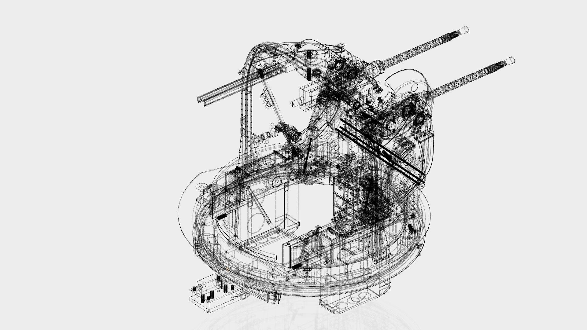
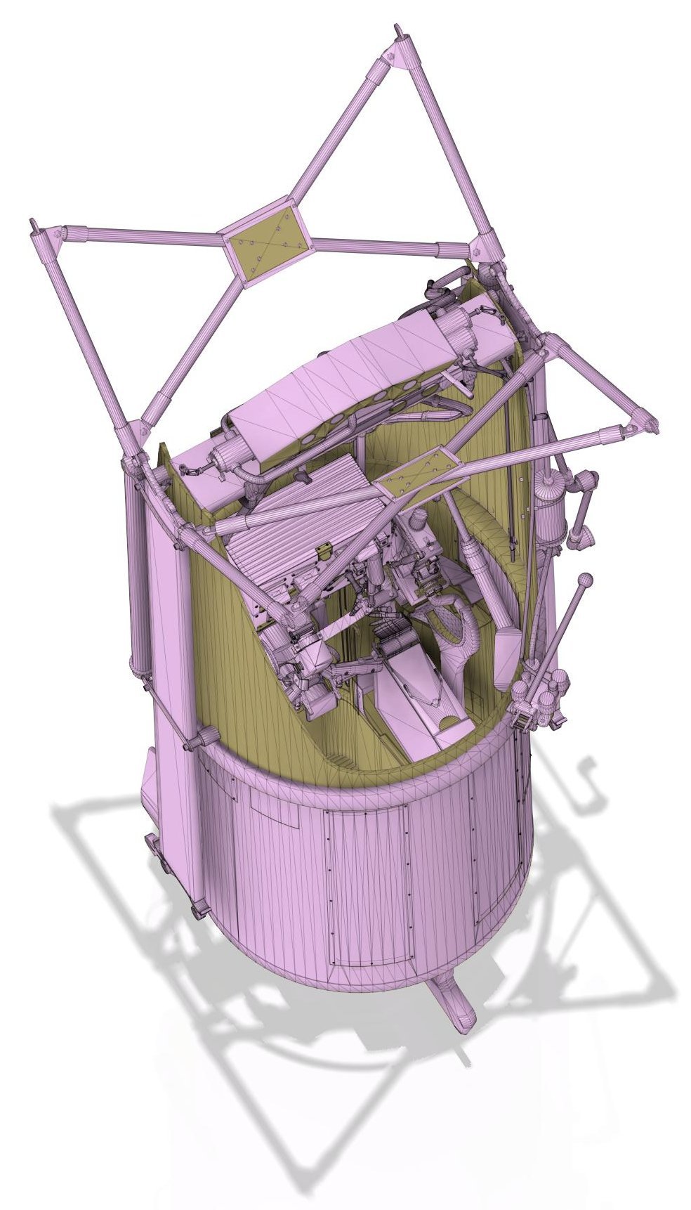
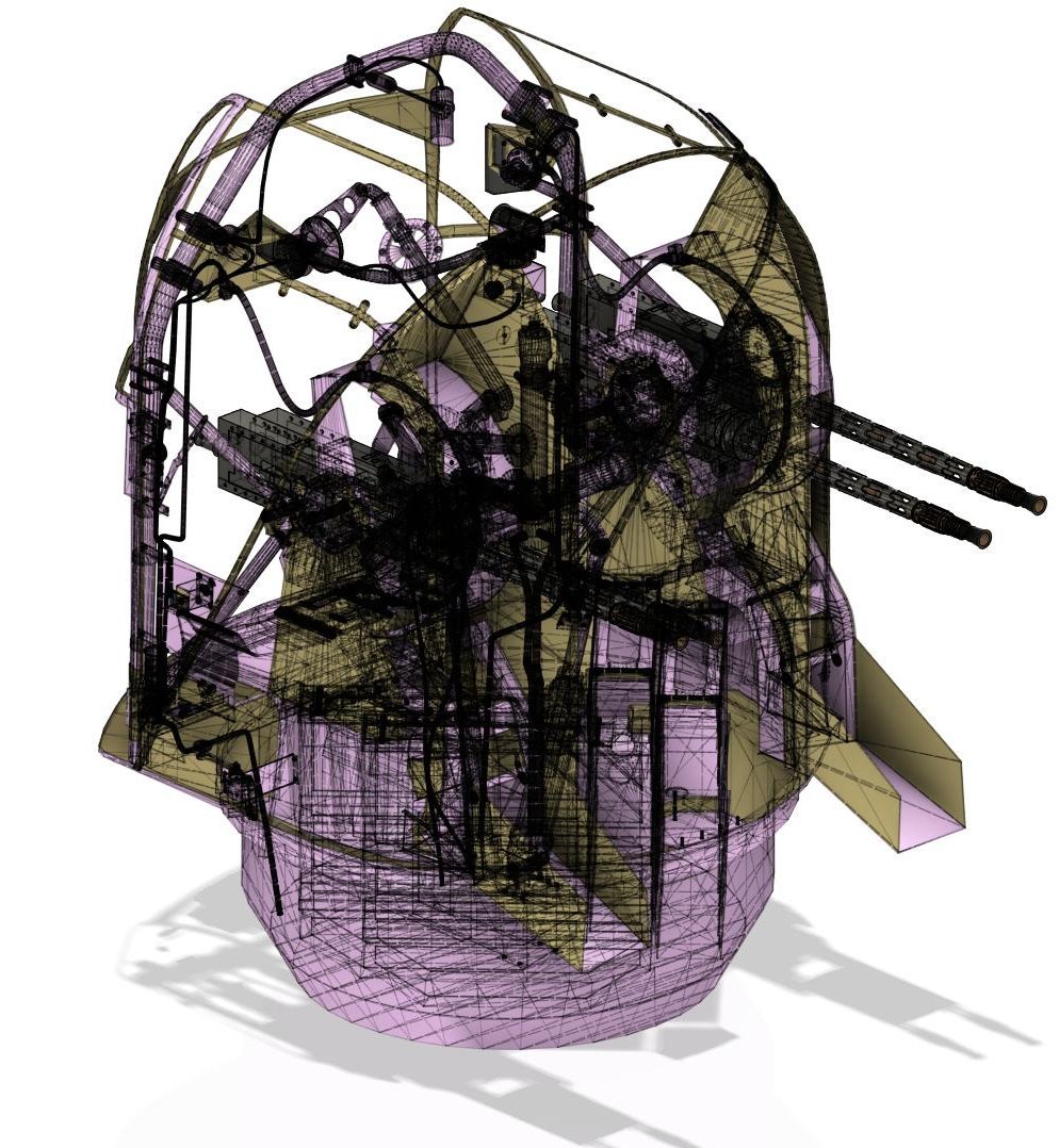
This too will eventually be a 3d-printed model turret kit. Many many hours are now required of CAD, to translate the wireframe into .step files of individual components, and a great deal of work checking the geometry. The FN25 was not a success, although technically it was very advanced. It had two hydraulic rams in the turret, for elevation, and a hydraulic pinion type motor for traverse. Additionally it had two rams to retract and deploy the turret, The gunner stepped down into it once it was deployed, "being very careful not to kick the jettison lever as he does so" (!) - from the manual. Although it defended the lower hemisphere well in theory, in practice the limited apertures for windows made acquiring and tracking fast moving targets all but impossible, whilst the deployment slowed the aircraft down by 15 knots just as all speed was needed!
I believe an FN25 was supplied to the USA, along with other specimen British turrets, which kick-started US efforts at turret design. It was probably accompanied by a note indicating the issues it suffered from in service, which is likely why Sperry were able to make such a good fist of their ball-turret, having seen a "here's how not to do it" example to look at.
The FN25 was later adapted to carry, instead of guns and a gunner etc, a single 24 inch naval searchlight, and used in conjunction with ASV radar to surprise and attack surfaced U-boats recharging their batteries. It was so successful at this, that the Germans reversed their previous procedure, recharging in daylight when they could see enemy aircraft, and submerging at night to remain hidden when they couldn't. Although 27 U-boats were sunk using the "Leigh Light" as it was known, even it it hasn't sunk one, it was hugely influential, as U-boats seen diving before an attack, in daylight had their position and course plotted making them much more likely to be subsequently attacked and sunk by destroyers or other aircraft the following day. It also kept the U-boats submerged for longer, reducing their range and speed.
Out of curiosity, if I released these turrets at circa 1:4 scale, as a pneumatically operable standalone model, probably made with resin parts, would there be any interest here making them, and if so, what might a comparably-sized resin model cost to buy? (roughly the size of a soccer-ball)
-
1
-
-
On 11/17/2019 at 4:20 PM, Wingco57 said:
actually 6176 + prototypes were produced.
After the bugs were ironed out it was a very good bomber.
Cees
It's probably truer to say that once they got rid of all the crap which threw the C of G aft and overloaded the tyres, it reverted to being "a good bomber"! Halifax woes were pretty much all due to two issues, overloading and disadvantageous movement of the C of G. The latter became a particular problem with the arrow-shaped and somewhat anaemic fin/rudder, partially corrected by the newer rectangular fins, but mostly corrected by a major heaving-session, at squadron level, of all the added "cool stuff" - extra armour plate etc, which had gradually accreted over the development of the aircraft. There was nothing, fundamentally, wrong with the airframe, imho.
-
2
-
-
Having costed-out the male mould pictured above, I had to devise a simpler and cheaper method. This has now been done, and the resin etc ordered. Instead the ABS pattern used to make the mould will be partially submerged in the resin to displace it, giving a wall-thickness of circa 50mm for the eventual vac-forming tool. I'll need to make a wooden structure to hold it down, to offset any buoyancy it may have before the resin cures, and to position it correctly. Tomorrows job.
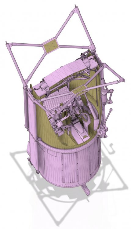
In the meantime, I got sent a ton of material from a chap in Newcastle, including an .obj drawing of an FN4 four-gun turret. This is effectively drawings of parts that are 2d, so I'm using it as a basis to create a drawing of parts suitable for production, eventually as a kit, printable in any scale between 1:1 and 1:10. It's fun to be working on something other than an FN5! I'm applying everything I learned doing the FN5, so the basic drawing has no holes or threads, but hole centres are marked. This will enable the scale to be changed to the customer's needs without having to rescale all the holes and sheet material thicknesses to metric integers, or decimals thereof.
The pic below shews progress, but it's a little misleading, as most of it is the 2d wireframe, rather than the 3d parts. After an evening at it, the guns, gun-sight and sight-bar are done. Lots still to do! Eventually I hope to add the principle Boulton-Paul turrets, and the FN's 5a, 50, 25, 17, 20 and 120 before embarking on American turrets.

-
1
-
-
Most interesting and as others have said, a real masterclass. I suppose one thing you need to keep an eye on is whether the fabric was applied in an continuous sheet, or if it was several sheets, at which point, assuming the pattern was pre-printed before application of the material to the airframe one would have occasional mismatch lines between adjacent rolls of material.
Or were the polygons painted onto the doped fabric?
-
3
-
-
On full-size aircraft, the standard repair procedure for small cracks in Perspex is to drill a hole at the furthest extent of the crack with a small drill, circa 2mm in diameter. If you wish to stop the current crack from propagating then just such a repair will work, although you'd need a very very fine drill-bit and a pin-vice (pennies from Amazon), if you do not already own one, to hold the drill as it's operated. And some "courage"! Doing nothing may work - but having the crack terminate in a circular hole, should stop it developing further, and would be by no means an unrealistic repair on a service aircraft. At your scale you'd want a 0.2mm drill bit, so the head of a heated [EDIT] sewing-needle [END EDIT] carefully applied, may serve to get the hole "scale"?
Of course such a repair is not used on pressurised cock-pits.
I should add that where available - possibly not employed on wartime aircraft, but certainly today, a clear adhesive can be applied into the crack in addition to the terminating hole being drilled. Again on modern aircraft, such a repair would not be favoured if the crack is at the eye-height of the pilot, in which situation the canopy or window-panel would be replaced entirely, at least in a professional maintenance outfit. The reason for this is that if the canopy becomes crazed with cracks at eye-height the tendency is for the eye to focus at the windscreen rather than at infinity, making on-coming aircraft very hard to spot if on a constant relative bearing - ie a collision threat.
-
6
-
-
46 minutes ago, airscale said:
..will probably start to sort out the rest of the glazing next - here a dry fit of the right cockpit windows...
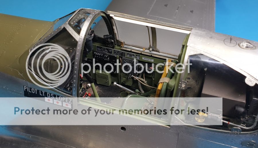
..still lots to do, but it's all bitty stuff
TTFN
Peter
My new desktop! Really incredible to see it being completed. I've love to see this model "in the flesh" so to speak.
-
4
-
-
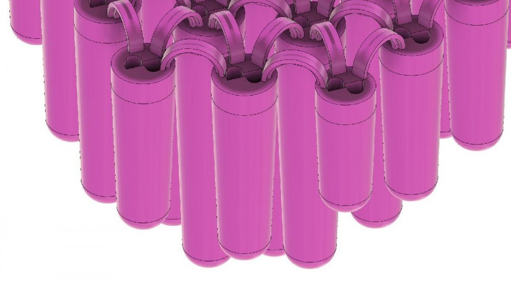
Cheers, following advice from a local vac-forming company, the cast resin needs to be circa 2" thick. Consequently I've designed a 2nd male mould to be 3d printed, the function of which is to displace resin from the mould, reducing the amount required, but to be removed post-cure to leave tapered cylindrical holes with round bottoms in the resin cast. These should transfer crushing loads to the walls of resin between each cylinder, in the manner of a vaulted mediaeval roof, and so help resist the tendency of the mould to collapse under full vacuum, which generates 1400lbs of force over the whole mould!
Incorporated in the male mould are two features, loops designed to keep the male moulds separate from each other, which will be snipped off post-cure, and shaped deep slots In the top, to allow them to be spun in situ with a screwdriver to aid in demoulding. I've designed these myself, so hopefully they'll work!
View of the "top" of the male mould (during casting process) which is actually the underside of the casting when cured.
-
2
-
-
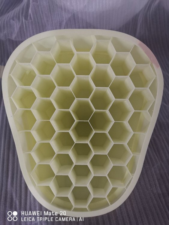
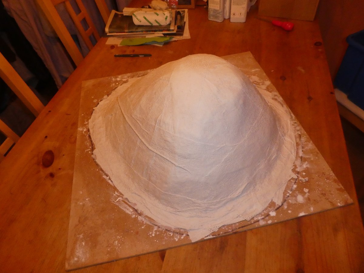
The saga of mould-making to vac-form the compound-curved windows for the turret cupolas continues:
Today I visited a local vac-forming company, who were brilliant in spending the time to help me understand the process and heat/forces involved. The upshot of these discussions is that I need to in corporate a honey-comb internal structure, even with the resin at circa 1 1/2" thick, as the cast as to withstand a "weight" of 1400 lbs over the 100 square inches or so of it's plan form. The easiest way to achieve this, and to economise on resin, will be to 3d print a series of hollow hexagonal plugs, linked at the top (ie above the level to which the resin is poured) and to withdraw these post cure, leaving hexagonal holes in the resin down to a distance of not less than 1 1/2" from the exterior face. I'll also radius these so that the load is spread to the walls of the hexagons, a bit like a vaulted ceiling. This male mould be simply be inserted once resin is in the female mould, and cramped into position displacing enough resin to bring the level to the top of the mould.
Since my last post, the mould and plaster shell were removed from the varnished base-board, and the interior of the silicone mould inspected fully, no bubbles, tears, stray hairs nor any other horrors. So far so good therefore! Film here: mould inverted and separated - no flaws!
-
1
-
-
The last few days have been spent drying the plaster, using a fan-heater and a de-humidifier in concert, I appear to have been wildly optimistic in thinking it would harden completely in two days! So instead I took a trip to Alchemie, purveyors of epoxy resin with infused with alloy powder, and talking over the cast with their R and D chap, who was enormously helpful. The current intention is to demould the original pattern, wax it, then use it to displace the casting resin so that we end up with a cast "shell" of uniform thickness, circa 1 inch. This should reduce the chance of damage through too much heat being given off as it hardens, as well as reducing the quantity of resin needed. (it can self-damage if too great a thickness of resin is cured in one go)
On Monday I'm off to a local vac-forming company, who will do the actual pulls, to check that what I produce in the casting is well suited to the process. Then will come sourcing the very thin acrylic in 0.5mm and 1mm sheet. More than 1mm won't fit, but 0.5mm may be just too insubstantial, so a certain amount of trial and error is required.
In the next day or two, once the plaster is fully dry, I'll be putting another thick-coat of plaster on top of the plaster-bandage currently encapsulating the mould, before finishing it off with another layer of bandage. I'm hoping this layered approach will result in a good strong and thick support for the silicone component of the mould. Getting it all to separate from the MDF board is going to be good sport!
Overall it's been a fascinating set of new skills to learn, although I'd not recommend making such a large expensive mould as one's first foray into using silicone/mould-making! Still, if it all works, and I get the pair of turrets cupolas glazed with correctly curved and optically clear acrylic, I shall be well chuffed, and it's given me a lot of confidence of future mould-making on the Wellington itself. I can see that on a smaller-scale, a lot of these processes would be useful for making home-made specialist resin parts for your kits, especially if several of you banded together to share the costs of materials and to teach each other...
-
1
-
-
2 hours ago, [CAT]CplSlade said:
While everything you said is true from the viewpoint of efficiency and reliability, you can't deny that the idea of the Tiger put panic in the hearts of the Allies, so much so that infantry were spooked by the idea of encountering one. What other tank has had that effect on its foes?
Hmm, that may be true, but then it's the "idea" of the Tiger, not the reality of it's actual effectiveness. The simple fact is that other tanks, especially the Mk IVH were frequently misidentified as the Tiger, and that any Flak 88 employed in the direct-fire AT role sounded exactly the same as the Tiger's 88, further adding to confusion. At typical ETO engagement ranges, both the Mk IVH and the Flak 88 (or come to that the Panther) could easily destroy any allied tank with the exception of a Mk VII Churchill. At which point, whether or not it was actually a Tiger becomes somewhat academic, although it added to the myth.
Precisely the same 'escalation of threat' was seen in Luftwaffe AAR's, in 1940, where the preponderance of Spitfires being ID'd as the type engaged was out of all proportion to the numbers employed relative to the Hurricane. In fact the Hurricane was both far more numerous, and, arguably, the better weapon, in respect of it being an excellent gun-platform for less experienced pilots but also because the types more basic construction permitted repairs to be done on station, rather than the factory repairs the Spitfire generally required.
Simplicity, reliability, survivability, offensive capability, ease of repair, upgrade potential, cheap cost, ease and flexibility of use - these are all virtues in military equipment. Frankly the Tiger only has two of them, and then only if it arrived in working in order in the Battle Area...
-
2
-
-
On 1/14/2020 at 9:12 AM, GazzaS said:
I'm sorry guys, but the baddest ass of them all was the Tiger I
Armor to defeat the best anti-tank belts... yes, anti-tank belts, not some lonely Ratch-bum hiding behind the only bush on the Steppe. And a gun and optics made to reach out and touch someone. No tank will ever mete out as much punishment or have a greater kill to loss ratio. When people think of tank, 70% or better think of this very baddass machine.
Gaz
The kill to loss ratio of a Tiger only stands up as a figure if you discount the numerous ones abandoned and lost from break-down (and that in turn omits all those which broke-down on the way to the battle!) I'm with Clunk, the last decent tank Jerry built in WW2 was the PzIII, the only exception, I think, being the Jagdpanther which had improved transmission over the Panther, and mounted a fearsome weapon, whilst being light enough to be generally employable, and reliable. Which certainly can't be said of the Tigers I or II, or indeed the standard Panther!
As to tanks being employed to break through ATG screens, that's the infantry's job. As Nelson said: "A ships a fool as fights a fort" - ie using a ship to attack a fort expressly designed to both withstand ships cannon, and possessing far more powerful and long-ranged cannon than the ship, and invariably both a height advantage and "resistance to sinking", it follows it's daft to use a ship to fight a fort. Even a 6pdr could knock-out a Tiger at 500 yards or so iirc, and at much greater ranges from the side or rear.....
As an overwatch weapon, it was good, however, provided it didn't have to move about, or travel far to get to the battle. Or have to retreat. Or rely on uncertain fuel resupply. Or cross bridges. (I could go on)
-
3
-
-
… and I've just uploaded the next film covering this:
-
2
-
-
So, a good day today. I've done the dovetailing to register the mould with the hard-shell (plaster/mod-roc) which will cover it, and very carefully prised the silicone from the pattern almost to the point of release at the top, before letting it close about the pattern again. Inspecting it inside out. This is to hopefully make it easier to separate the silicone from the base-board once the shell is applied, reducing the overall force needed to separate the plaster shell from the base-board in turn. This all being a new process to me it's a case of lots of research, talking to people who have done it before, and lots of thought before each stage.
Pleasingly I could see not evidence of either air-bubbles in the internal face of the silicone mould, nor any un-catalysed silicone remaining sticky rather than cured. This had been a bit of a worry, as after the 1st coat I'd noticed some slight "veins" of uncatalyzed silicone. I decided at that point to proceed and hope for the best, in the hope enough catalyst had mixed in the veins to nevertheless cure it, despite appearances. This proved to be the case, and with £150 quids-worth of silicone at stake, was a most welcome discovery. If the costs are high, bear in mind that to get this done commercially, I was looking at ten times the cost!
So, now that the silicone is cured and de-bonded from the varnished base-board, the next phase is a good covering of mod-roc (plaster infused bandage strip) before some thick layers of Plaster of Paris, and then a final binding with Mod-roc, which will give an overall thickness of the hard-shell of around 2 inches. In order to reduce the possibility of the plaster cracking in the exothermic reaction as it hardens, I'll probably need to do that in several hits, rather than all at once. The final stage will be to incorporate some sort of feet or runner's into the plaster, so that when inverted, the casting mould can sit level.
The moulding of the vac-forming pattern in alloy-powder infused epoxy resin can then begin. I'm aiming for an inch thick lay-up, backed with a generous amount of chopped glass-fibre, which should result in a polishable "metal" mould ideal for vac-forming and super smooth. The latter is critical, is the whole point of this is to end up with an optically clear cupola, so that footage taken from cameras within can show the outside world un-deformed by imperfections on the mould being rendered in the hot-pulled acrylic. It's "shooting for the moon" a bit, as this whole process from start to finish is new to me, although I've done carbon-fibre work in the past.
Wish me luck!

-
2
-
-
Hi again all.
Blimey using silicone is a mucky business! You know when you get a bit of wrinkled sellotape stuck to your finger and you can't get rid of it, and end up merely transferring it from hand to hand in utter frustration? Silicone is like that a thousand-fold. No matter your good intentions and resolution for working cleanly and efficiently, one ends up like a 5 year old left momentarily unsupervised in a toffee-factory! Good "clean" fun and very interesting.
So I've started by using a catalysed T28 silicone for the initial "skin" coat - equivalent to the gel-coat if fibreglassing - which had the consistency of syrup and was the very devil to keep from overlapping the clay dam I'd made. This was suitable after 2 hours for the "thixo'ed" coat, which is much stiffer, - more akin to boarding-school porridge! - and was moved up towards the top of the pattern from below, as it practically "stands-up" even before curing. In two hours I'll do the final coat, and in 5 should be able to trim off the surplus silicone and cut the dovetails. I'll then leave it a couple of days - maybe 3 - before commencing the "Mod-roc" and "Plaster of Paris" hard shell. I'll make this thick enough to embed some rawlplugs, for attaching feet to the mould for when it's later inverted for casting.
Films in the usual place, first two here if anyone is interested. As usual, if it all still goes wrong, I'll leave the films up in case it helps anyone else!
-
2
-
-
Breath-taking. Do you know, that if the only thing you'd made was that tail-wheel assembly, I'd still be massively impressed. Seeing all this, I can't help thinking that the next stage for your incredible model-making skills, would be to go the whole hog and build the entirety of the internal-economy of the aircraft ribs, stringers longerons, the lot, and affix the amazing metal-panels to it.
Regarding varnishes/lacquers: As I see it there are two main issues. It needs to be removeable with a solvent if for any reason you later wish to get rid of it. Such solvent needs to be safe with other materials used. And it needs to be robust but essentially invisible, even after a considerable period (it doesn't want to age-yellow for example). I can't suggest which precise varnish or lacquer would do, but one has to think that the previously stated requirements would greatly narrow the field.
Maybe take some parts you've replaced and try out a number of lacquers/varnishes on different parts, making notes of what is used where, leave it on a sunny window-sill for 2 years and review?
If you're using Alclad paints, they have both matt and gloss varnishes for airbrush use, which go well over painted surfaces. The gloss one is more semi-gloss in my experience. Decals would require pre-treatment, as they tend to go cloudy in my experience, under these varnishes.
-
2
-
-
A really well executed model of a very imaginative subject. Few people would see a pile of old aircraft bits and think to model that, rather than the aircraft in flying-condition. Outstanding, in every way.
-
1
-
-
Ok..... as "Blackadder" would say: "I have a cunning plan"!
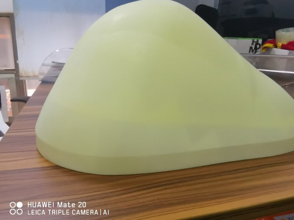
The first problem, is that I learned to my utter dismay, that the melting point of ABS is lower than that of acylic sheet heated to vac-forming temperature. Doh!
So, the ABS shape above simply cannot be vac-formed over directly.
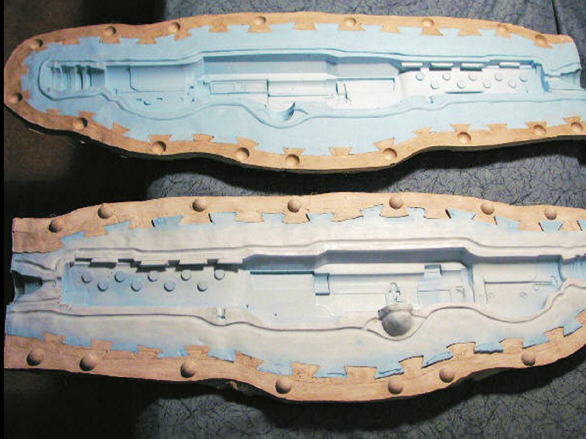
Instead I have to make a mould:
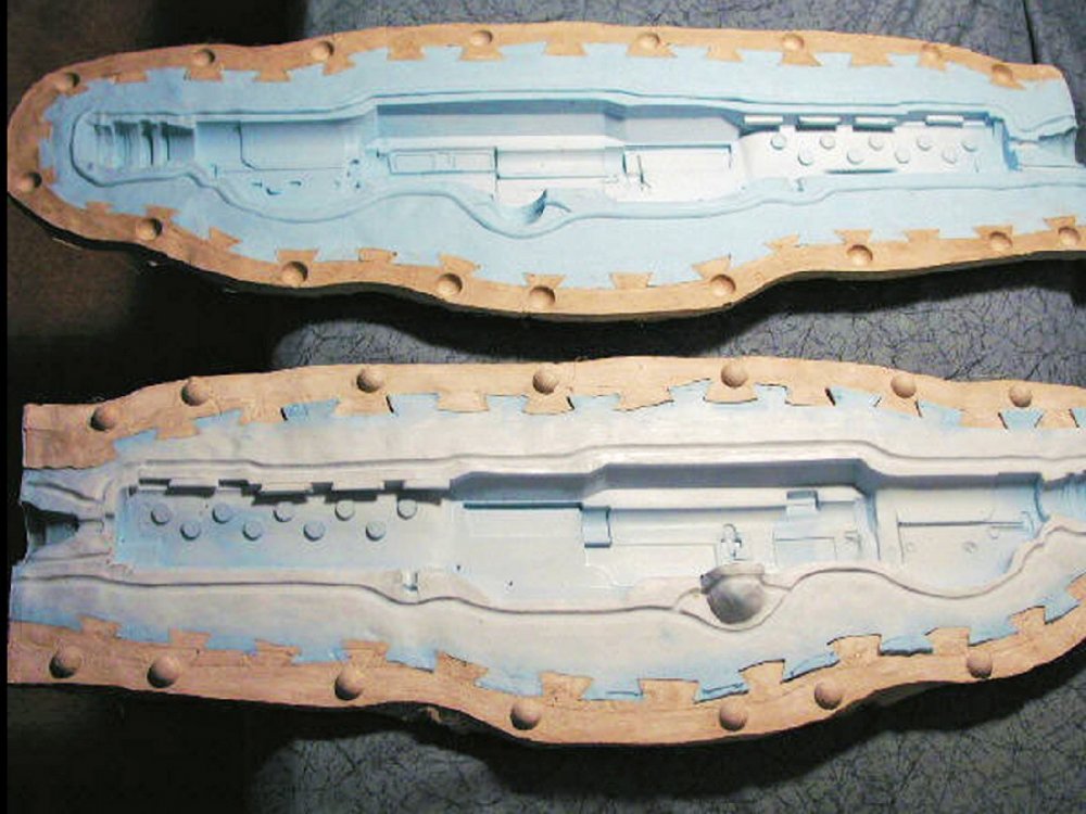
I'll start by securing the ABS shape to a board covered in clingfilm. The ABS shape is then painted with about 3/4 inch or more of silicone rubber with thixotropic additives, extending over the shape and 2 inches wider than the shape all around. When that has cured in situ, dovetails are cut into the silicone around the flat periphery of the silicone. Then the silicone is covered with 'Plaster of Paris' to a depth of an inch and a half or so, and whilst still wet, the P' of P' is covered by the thickest possible layer of Plaster of Paris impregnated material - "Mod-roc".
The Plaster of Paris/Mod-roc lump demoulds leaving the silicone adhering to the ABS shape, which is then demoulded in turn before being placed back into the P' of P' section of the mould, the dovetails helping to register one with the other. The silicone is then cleaned carefully with plain water so as not to leach out the chemicals which prevent it adhering to the casting material. Finally, the silicone mould, now in it's hard surrounding P' of P' is filled with high-temperature-tolerant resin and bulking material, which cures in situ. Once cured, the mould again demoulds leaving the silicone attached to the casting, which can then be carefully removed leaving the pristine and dimensionally accurate plug over which hot acrylic can be safely vac-formed.
Which should result in some nifty properly curved windows for the front of the turret, from roughly 60 degrees either side of straight ahead. The side and top window panels will be made in flat sheet, bolted in place and then softened with a hair-dryer to conform as required to the gentle compound curves required. With a little luck this will obviate the need for a 2nd mould.
Pictures and films to follow as this gets under-weigh. Sorry I've not been updating much, but I've been busy figuring this out and learning the required techniques.
Pictures attached are those of the yet-to-arrive ABS shape. The 3rd picture shews the dovetails registering the silicone with the hard Plaster of Paris case, although in this picture it is a 2 part, rather than 1 part mould. Same principle however.
-
1
-
1
-
-
Beautiful! I love the finish on the doped-fabric, just magic! Only an observation, and it may be the angle I'm looking at it, or some peculiarity of this aircraft, but the ailerons appear to be deflected as if rolling to the left, but the stick appears central(ish) whereas I'm guessing it should be laying to the left of vertical, (and perhaps forward a touch?) looking at the ailerons and elevator?
Parked, light fighters like this usually would have the stick tied back with the lap-straps, to give full up-elevator, in effect helping prevent the tail from lifting in high-winds (the tail-plane and elevator exerting, therefore, a down-force whilst the wing remains "stalled"). This in turn helped prevent the wind getting under a wing and un-stalling it, and has the other benefit of preventing the control-surfaces being slapped back and forth by the wind which can do serious damage. Also common, would have been to tie-down the wings with loose-ropes to large stones or sand-bags (I'd expect the latter may well have been placed over the wheel axle?). Loose ropes being used as the dew over-night can cause them to shrink, potentially exerting damaging forces on the airframe if they become taut..
-
2
-
-
Sorry, I wasn't saying your model was in any way incorrect, it merely struck me as quite a coincidence. If you think about it, the odds are roughly 400,000 or so to 1 against of the sqn number and sqn code randomly arising in this way!
-
2
-
1
-
-
Interesting registration letters too, iirc "AJ" was the wartime squadron code for "617" Sqn of Dam-Busters fame? - AJ617?
-
2
-
-
My father learnt to fly in one of those in Terrel, Texas, then 1 BFTS, in 1944. I'd give me eye-teeth for one of those well modelled in his colours. (pics available). I was never able to establish the colour scheme, which looks to be fairly unadorned factory finish with USAF markings. I have been unable to research the markings under the wing, and the only pictures I have are tinted black and white..
-
4
-


Blimey! never seen one of these used before..
in General Discussion
Posted
Isn't the normal method some Tamiya putty and a blunt knife-blade or clay sculpting tool?