


James H
-
Posts
3,255 -
Joined
-
Last visited
Content Type
Profiles
Forums
Events
Gallery
Posts posted by James H
-
-
Oh, and if anyone wants one, I have a code that I'm told will give 16% off.
-
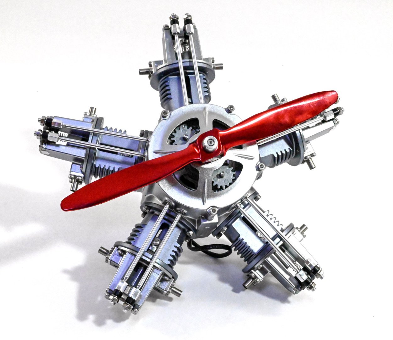
Here is the main event! The model is actually quite large and weighty, and we haven't finished yet. The ejector rods and sleeves are now to be fitted. This is done one cylinder at a time, and needs to the rocker arms to be lifted to allow the ejector rods to sit.
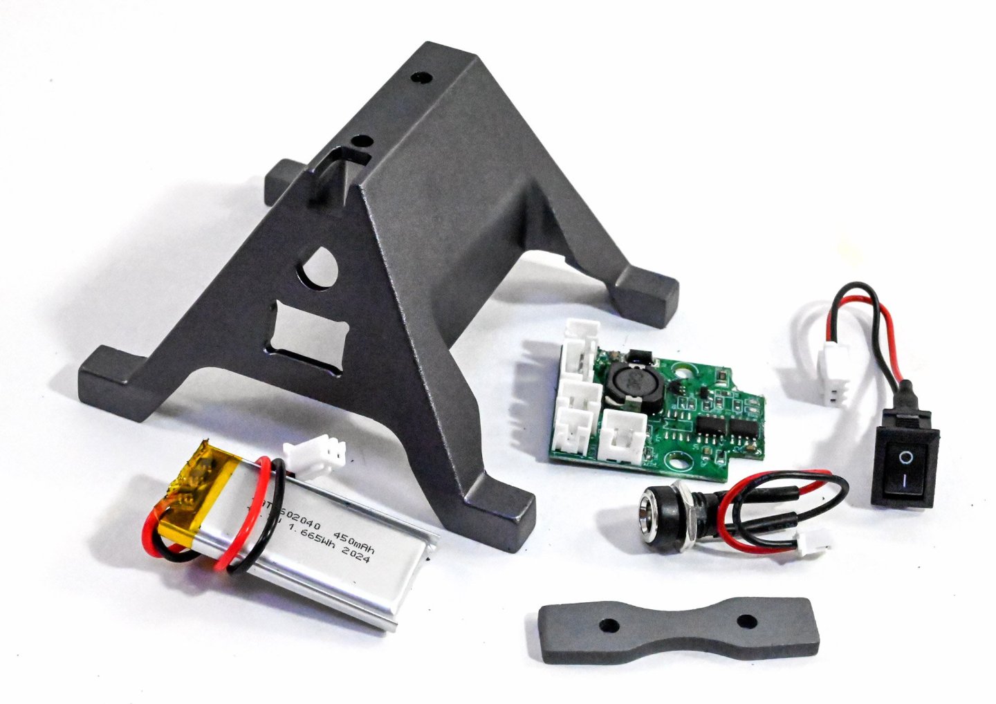
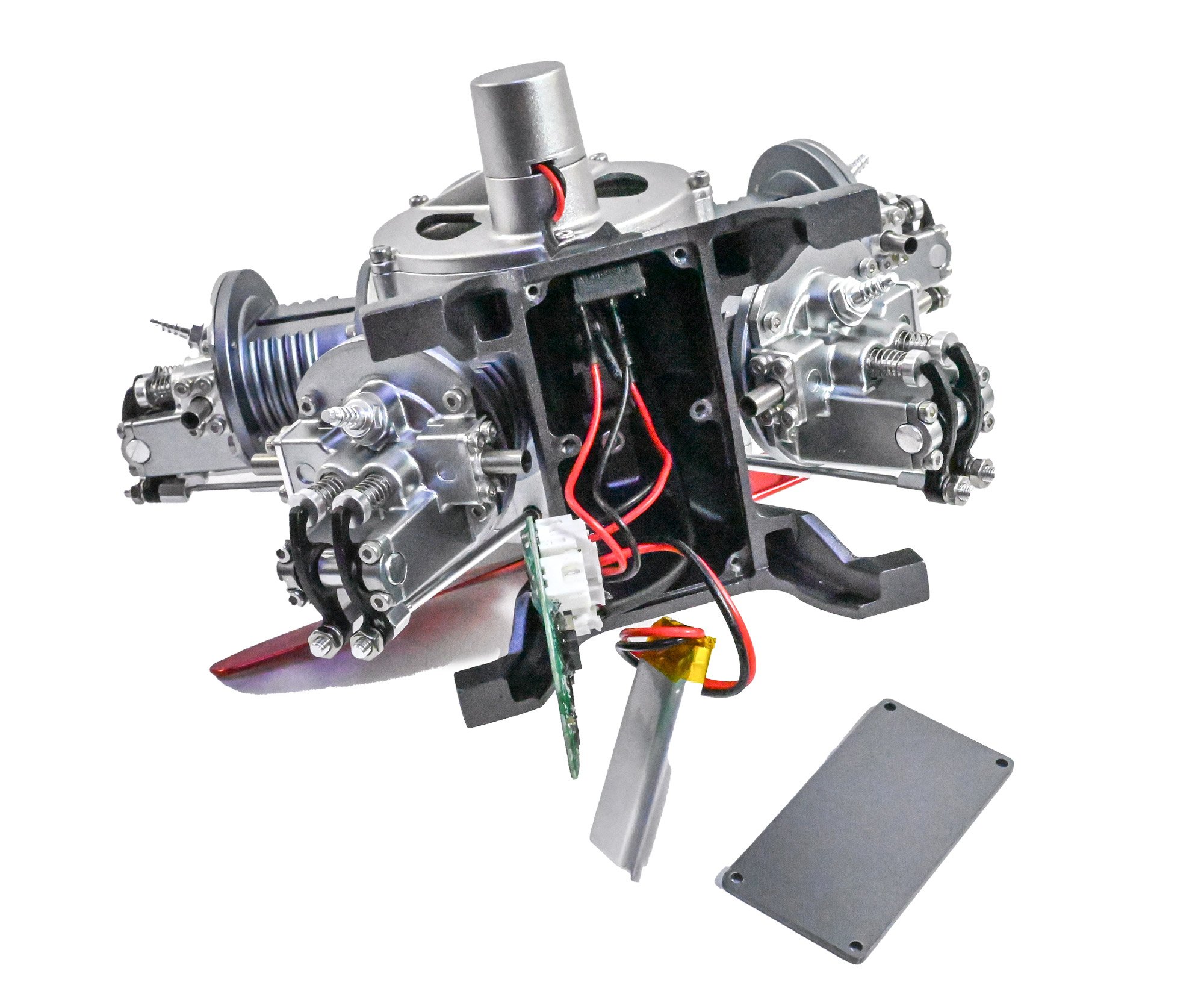
The base is now fitted, and a spacer mounted between the base and engine. Once fitted, the battery charger port, switch and motor cables are threaded into the base. The cables are then plugged into a control board, along with a battery pack. The circuit is then screwed into the base and a cover fitted to hide it all. The kit also includes a USB charging cable too (not shown).
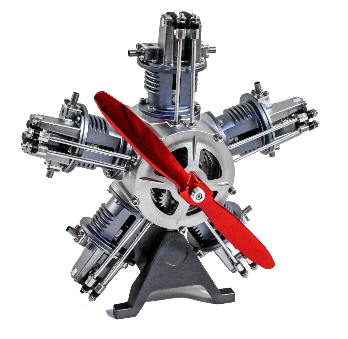
COMPLETE!
And here is a video I made of my review build.
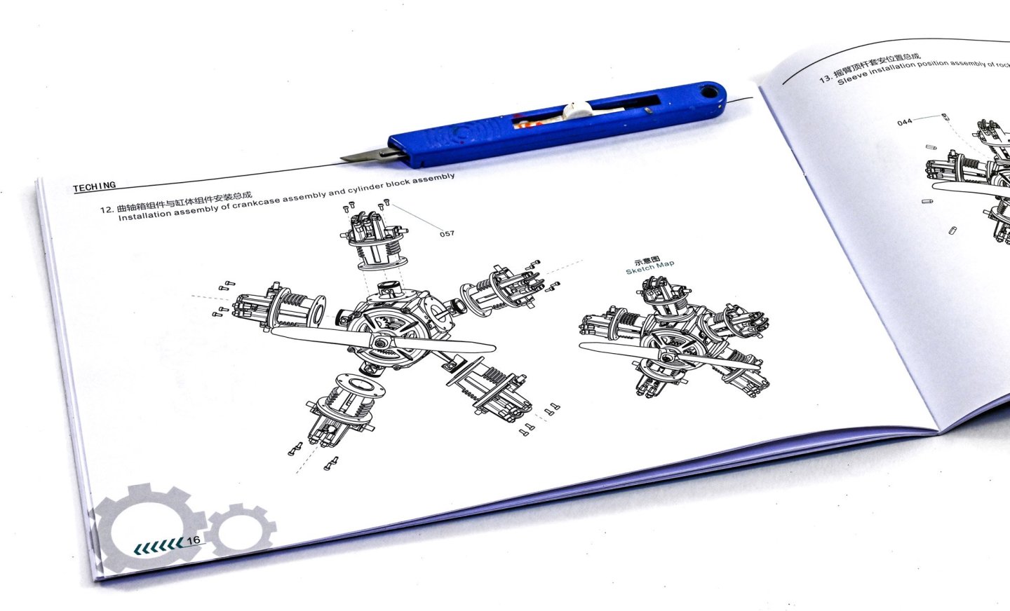
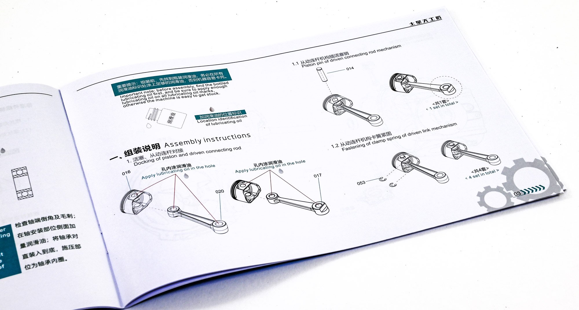
The instruction manual is clearly illustrated and the average builder should find zero difficulty in following each stage.


Conclusion
I didn't know what to expect before seeing this kit in the flesh, and I was very pleasantly surprised. I'd had a hankering for building something like this for a while, but I suspect the mixed reviews I'd seen were from cheap copies. This kit very much surpasses my expectations in presentation, quality, and also the final result. This model took me about 5hrs to complete, but that's also because I was setting up photos of each stage. I think it's fair to say that the manufacturer expectation of about 3hrs is reasonably accurate. The instructions are very easy to follow and should present no problems, even to a beginner who has no sort of modelling or engineering experience. All parts fit perfectly together with no issue. The only things I would criticise are the hex keys which are a little soft and round off easily, making tightening the screws hard. Also, there is no lube in this kit any longer, so you will need to source your own. In all, a fantastic kit.
My sincere thanks to EngineDIY for sending out this kit for review on Large Scale Modeller. I'm more than sure you'd really enjoy this one. To buy direct, click the link in the header of this topic.

-
 1
1
-
 3
3
-
-
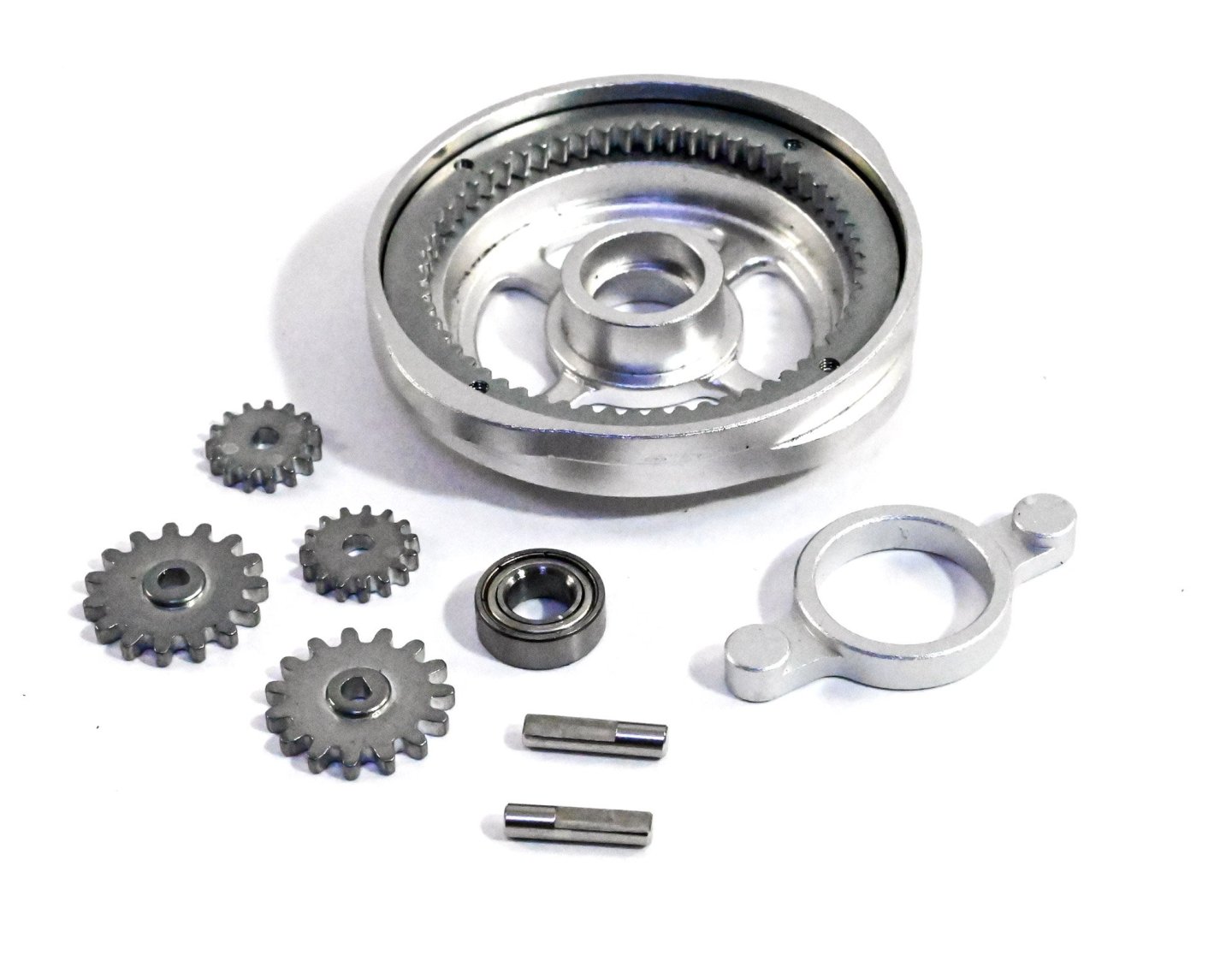
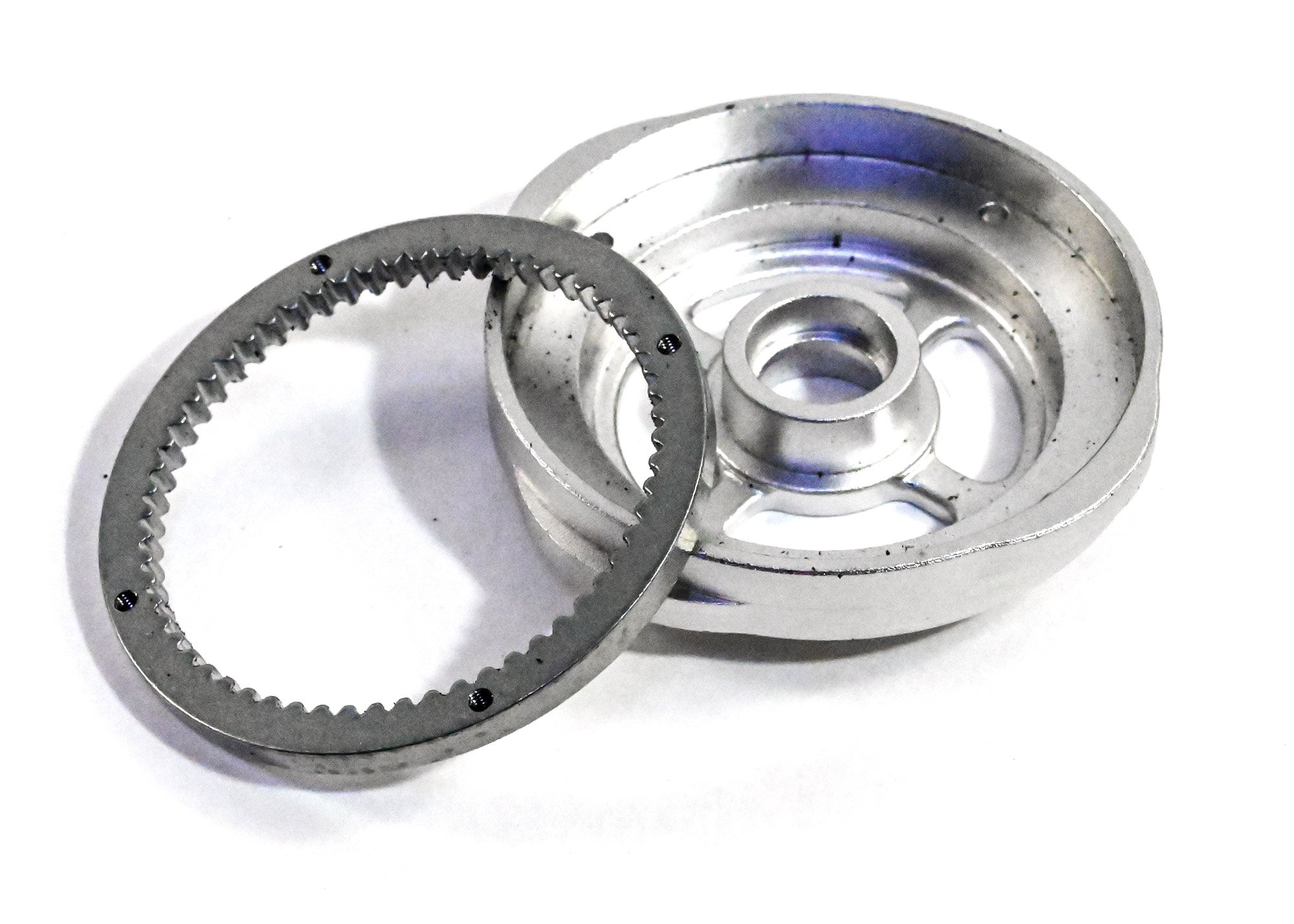
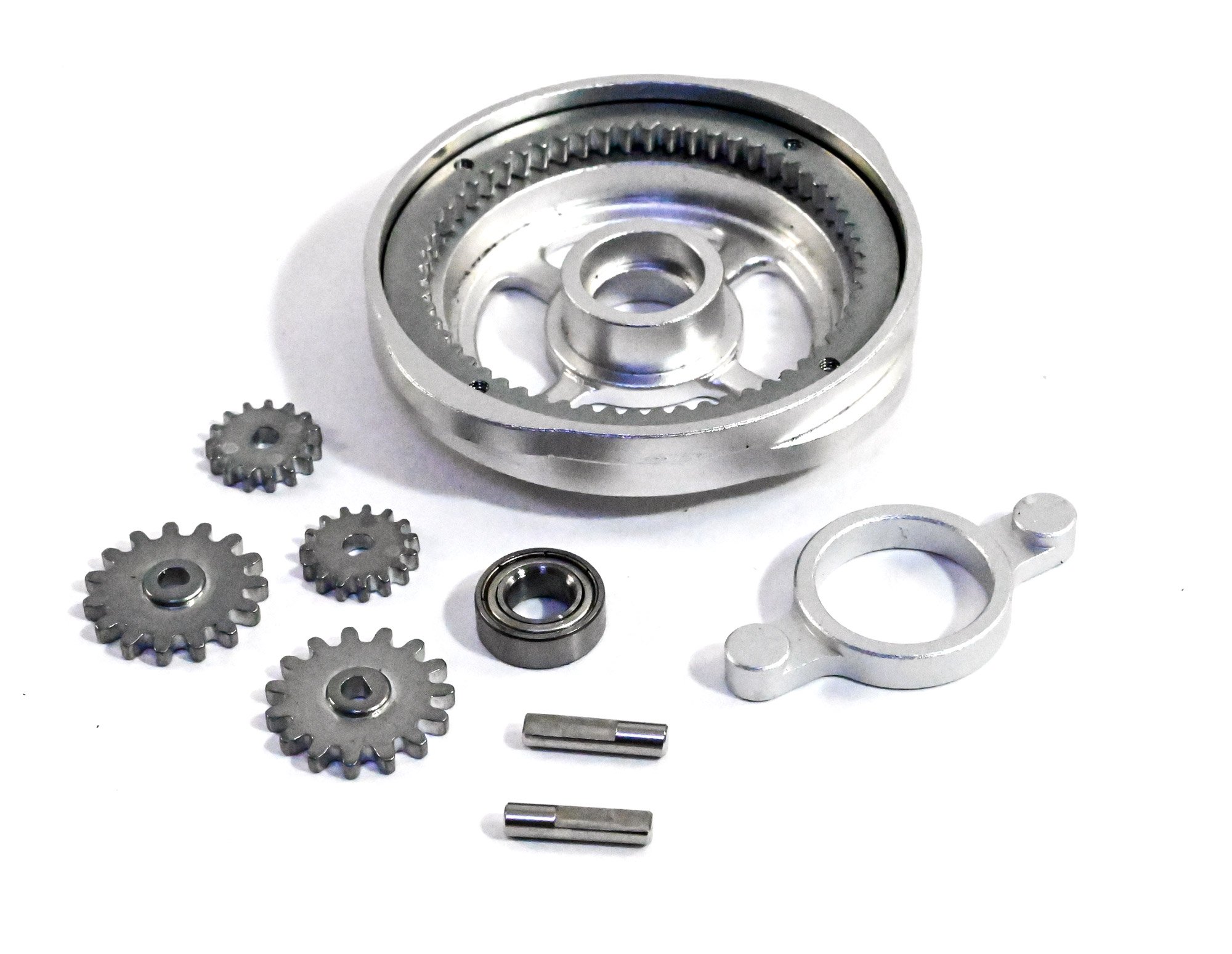
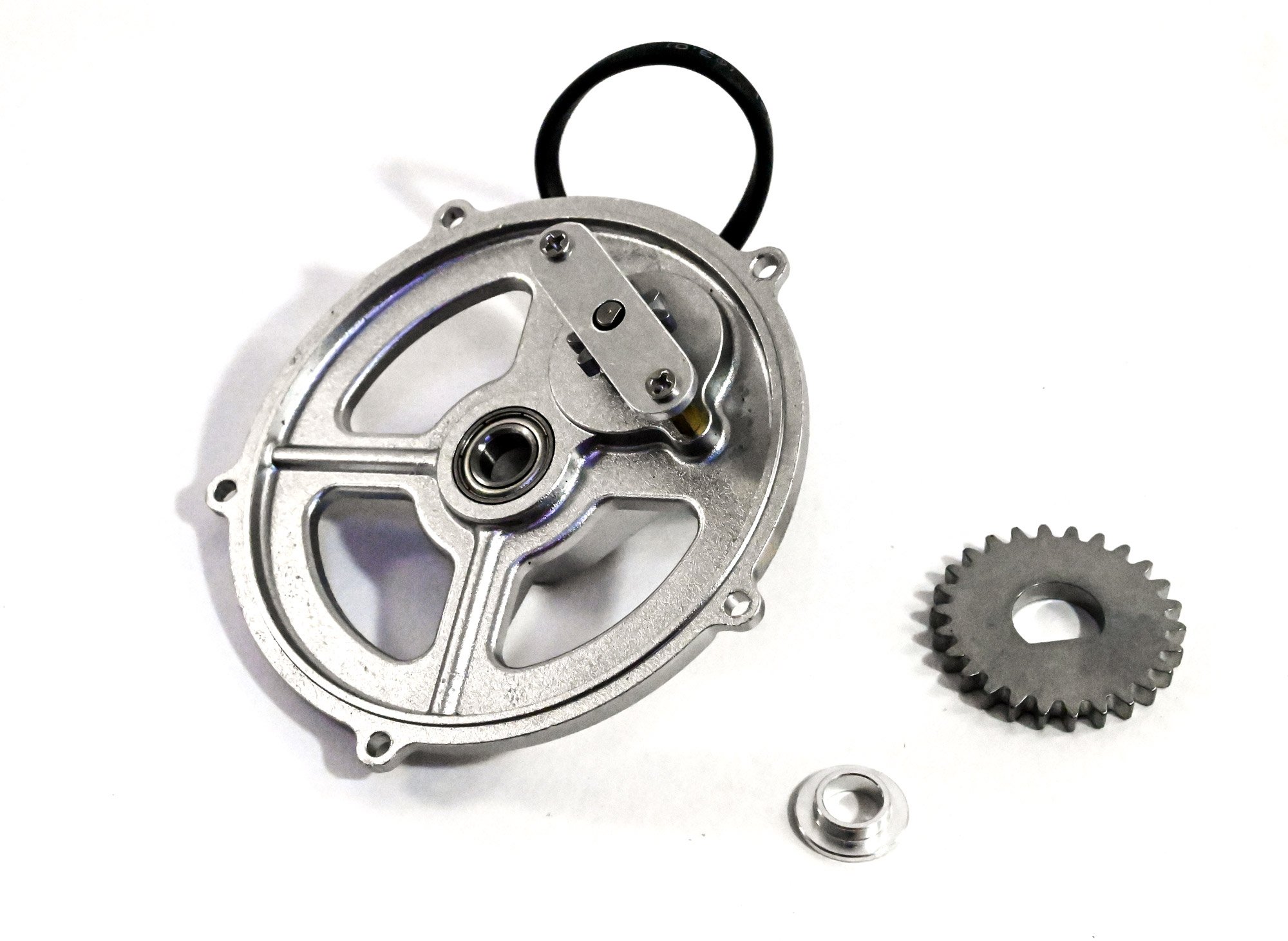
If you see any black flecks as are visible here, these are just some debris from the foam trays. Parts with this are just blown clear before assembly. Here are the cam and gear which are simply fastened with four small screws.

The cam drive gears are now selected and assembled as shown. You'll notice the mounting pins are machined to accept the gears. The gears must also be fitted in the orientation shown in the manual.
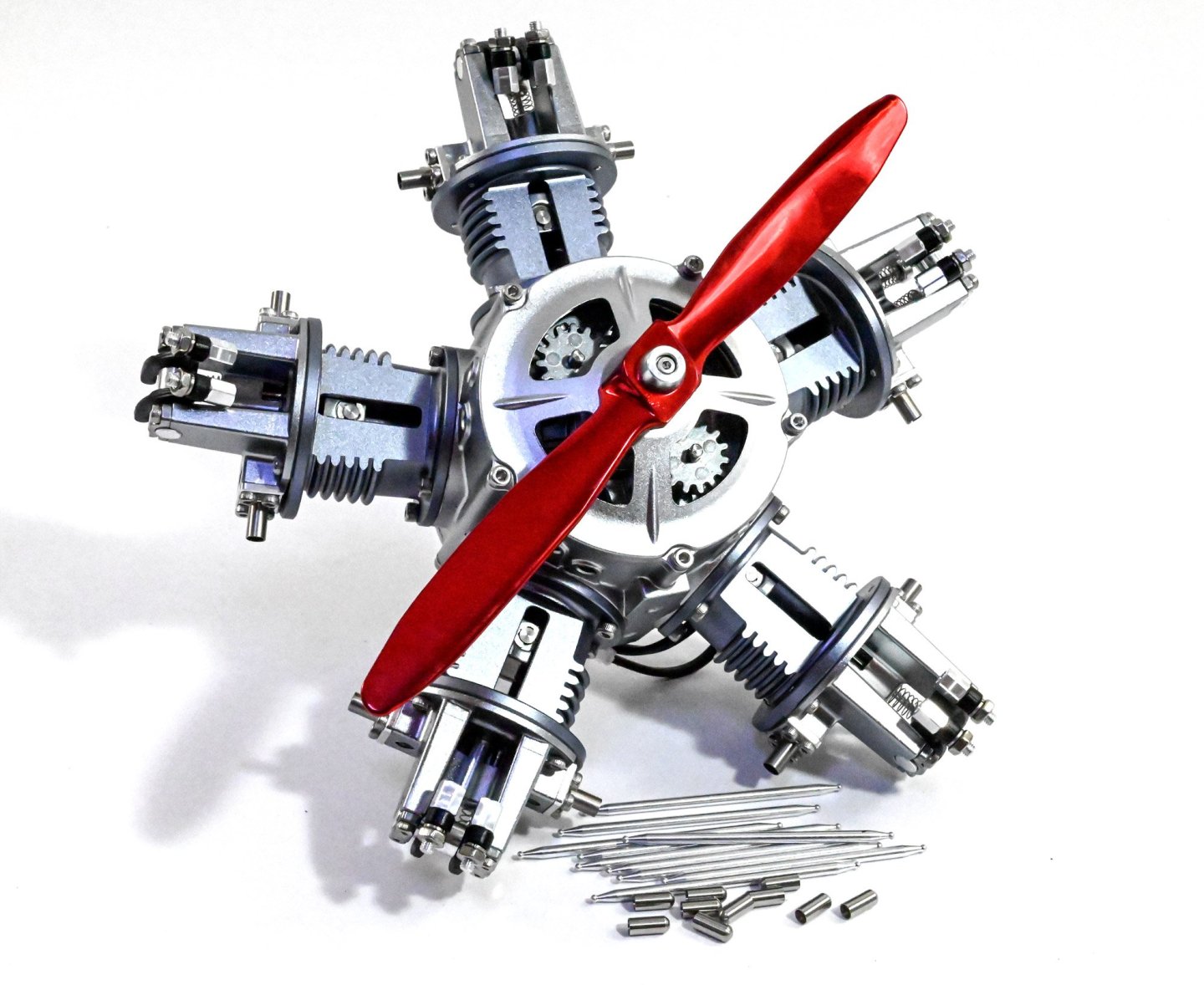
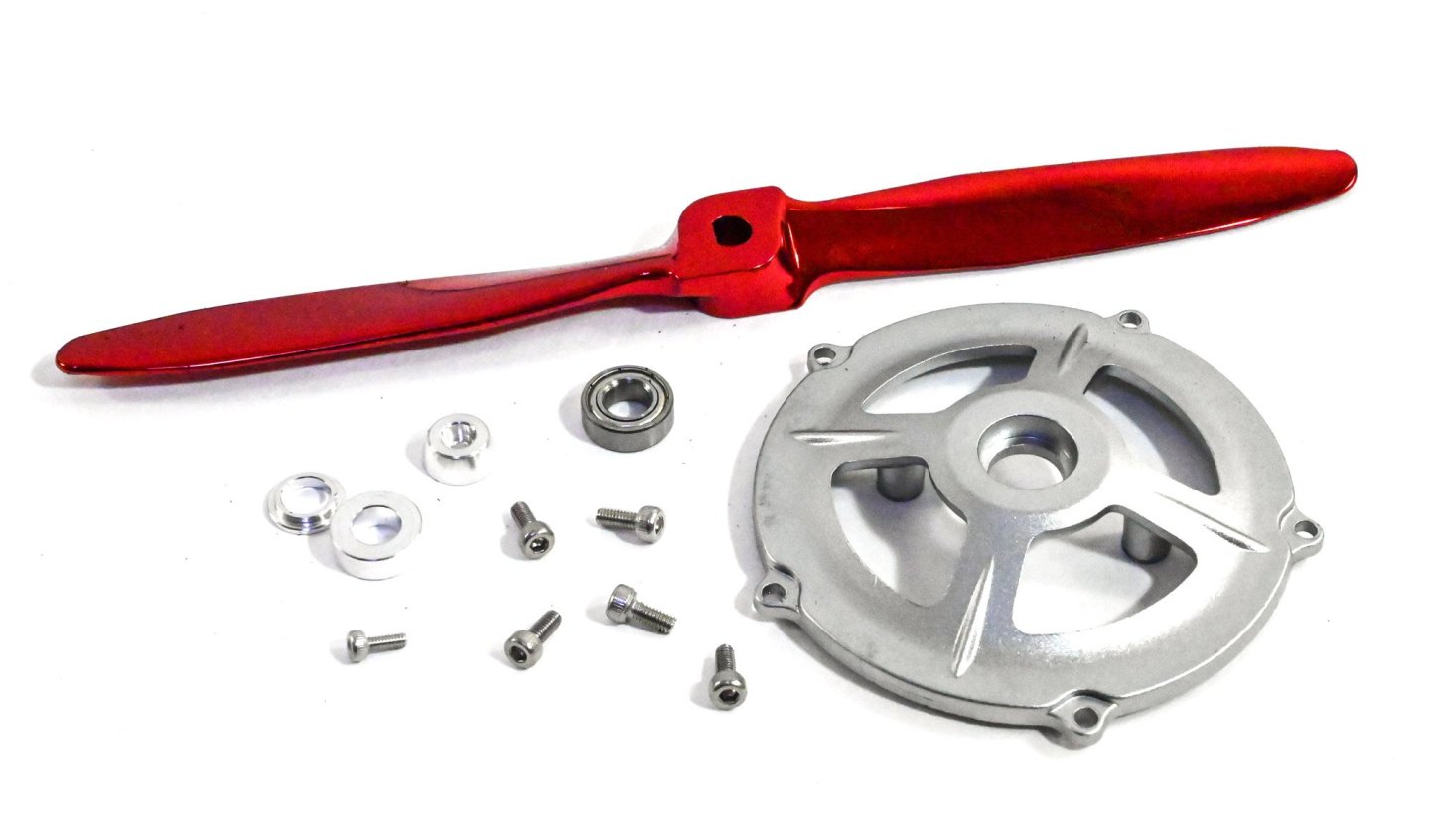
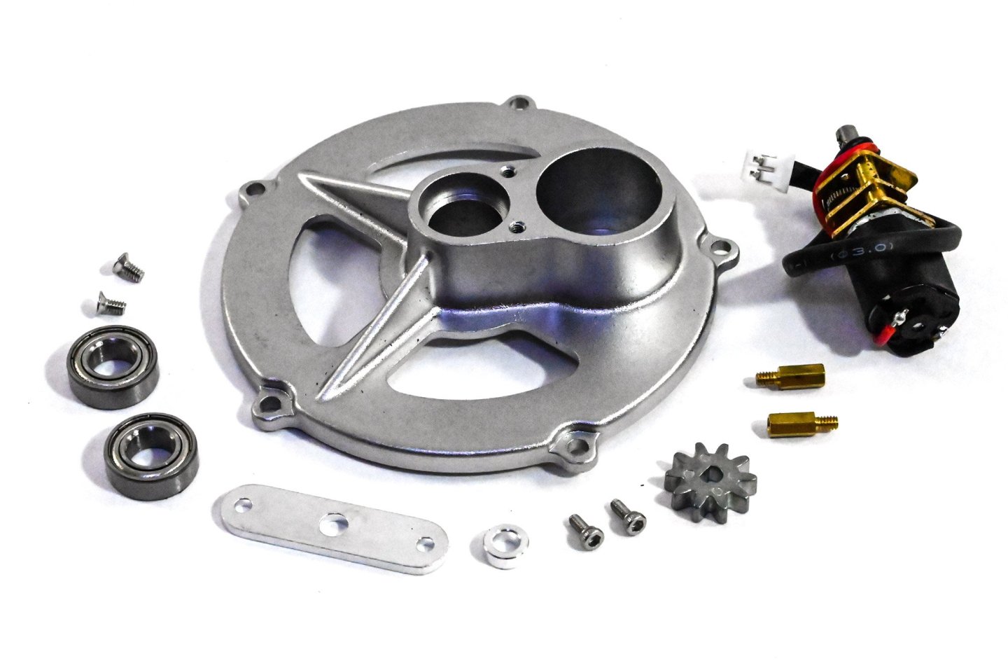
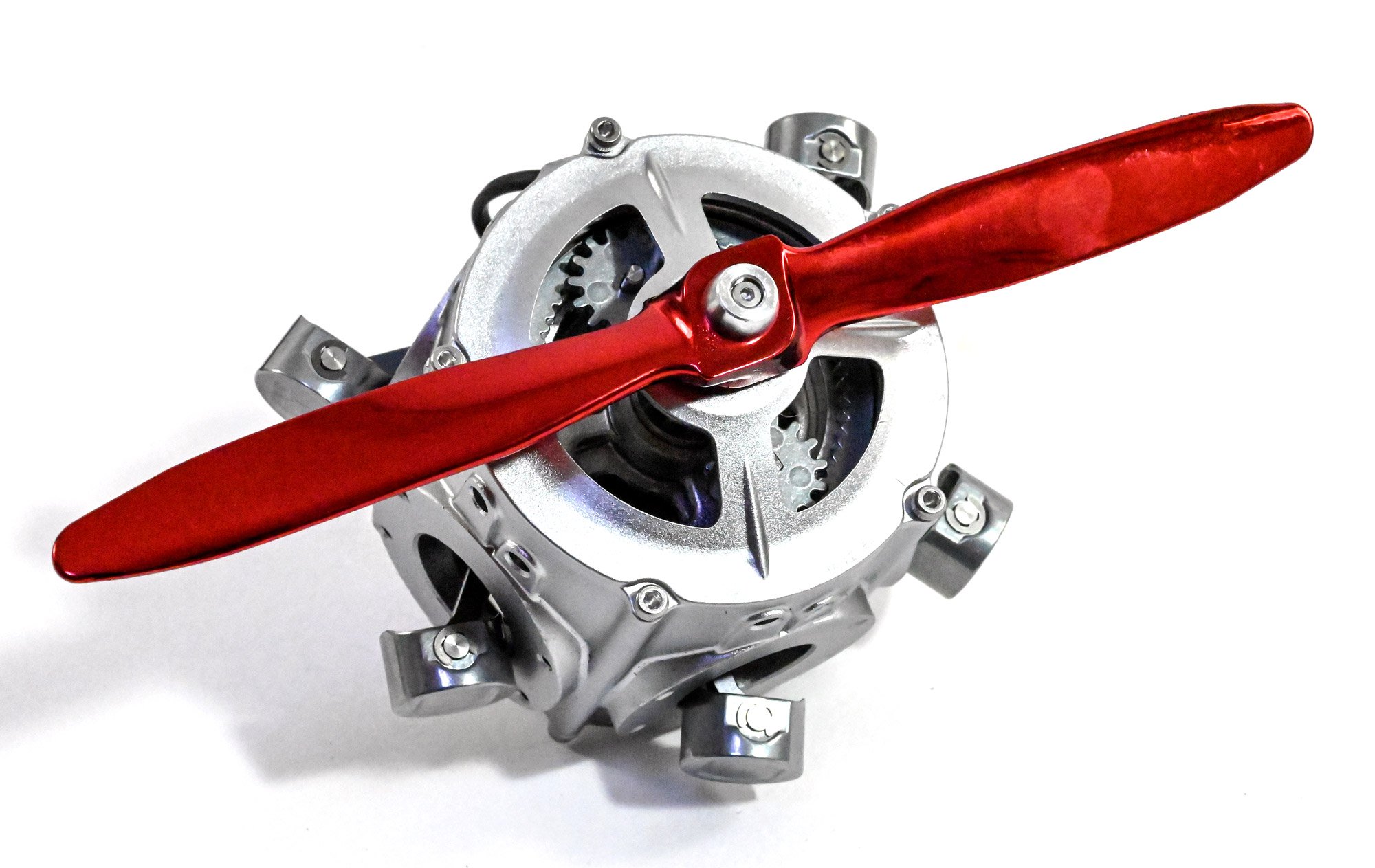
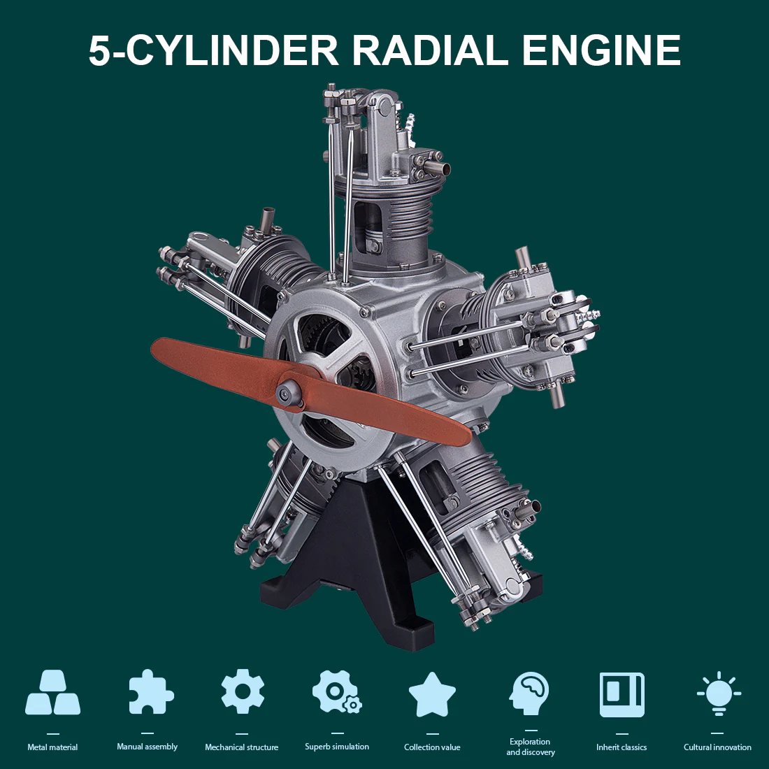
Yes, you see that correctly....a metallic red prop! Whilst I understand that it's better to include a machined metal prop as there won't be any balance issues, I might well have selected a different colour to anodise it. Still, this is a display model and it does looks strangely attractive when fitted. Here you see the prop and the front crankcase with the bearing, collar and prop hub parts.

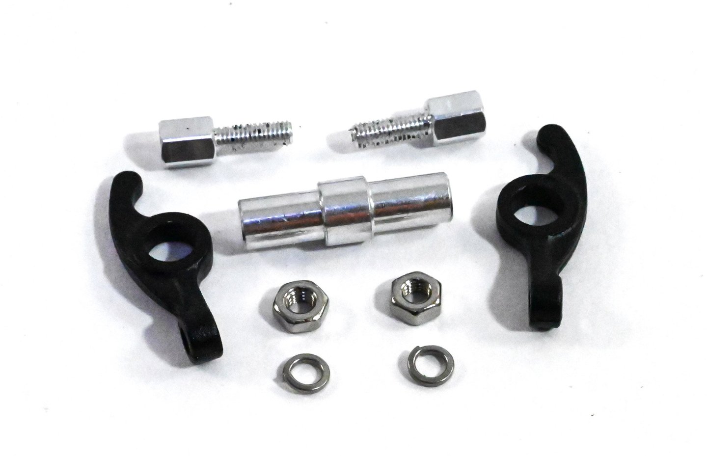
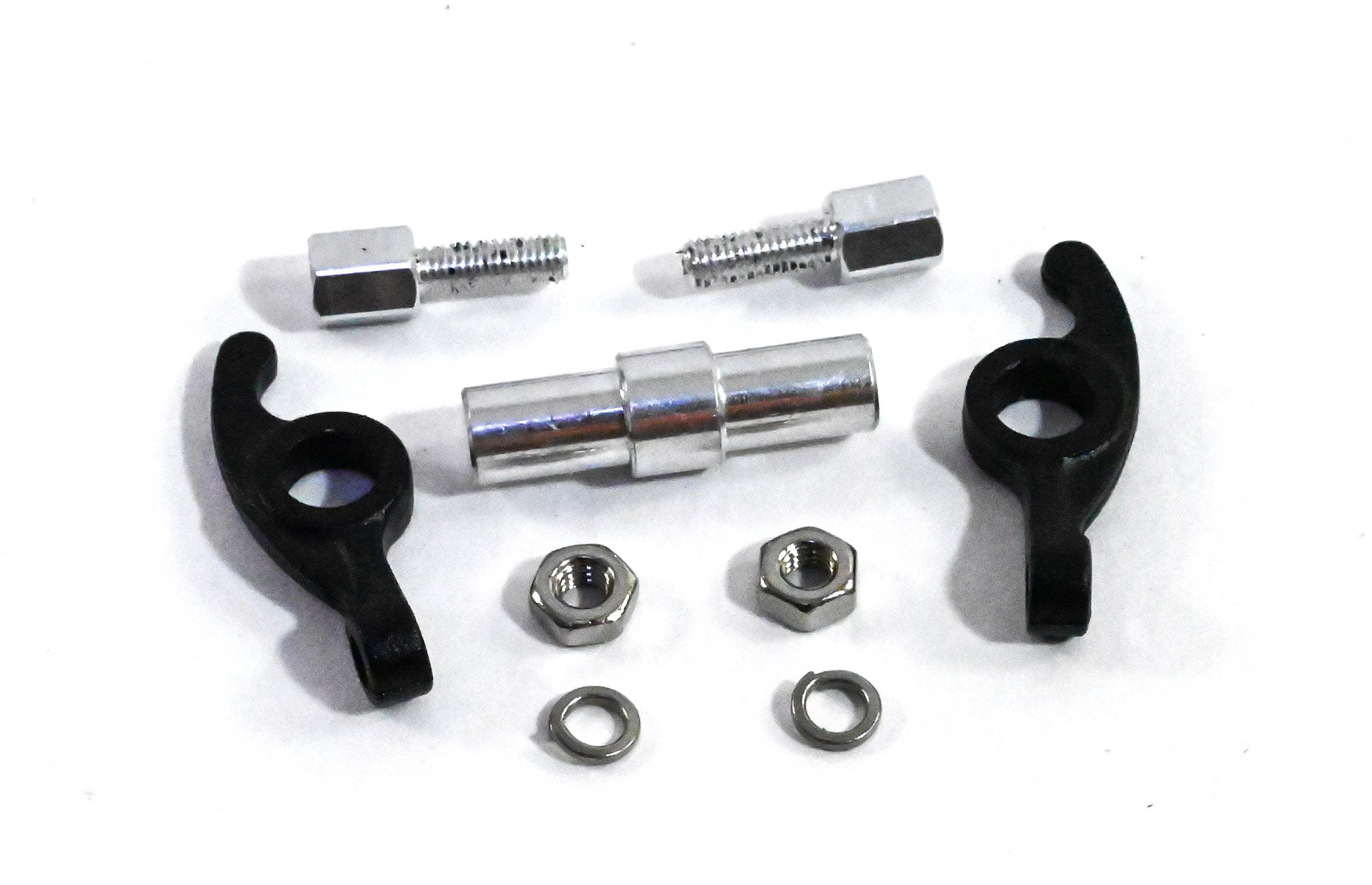
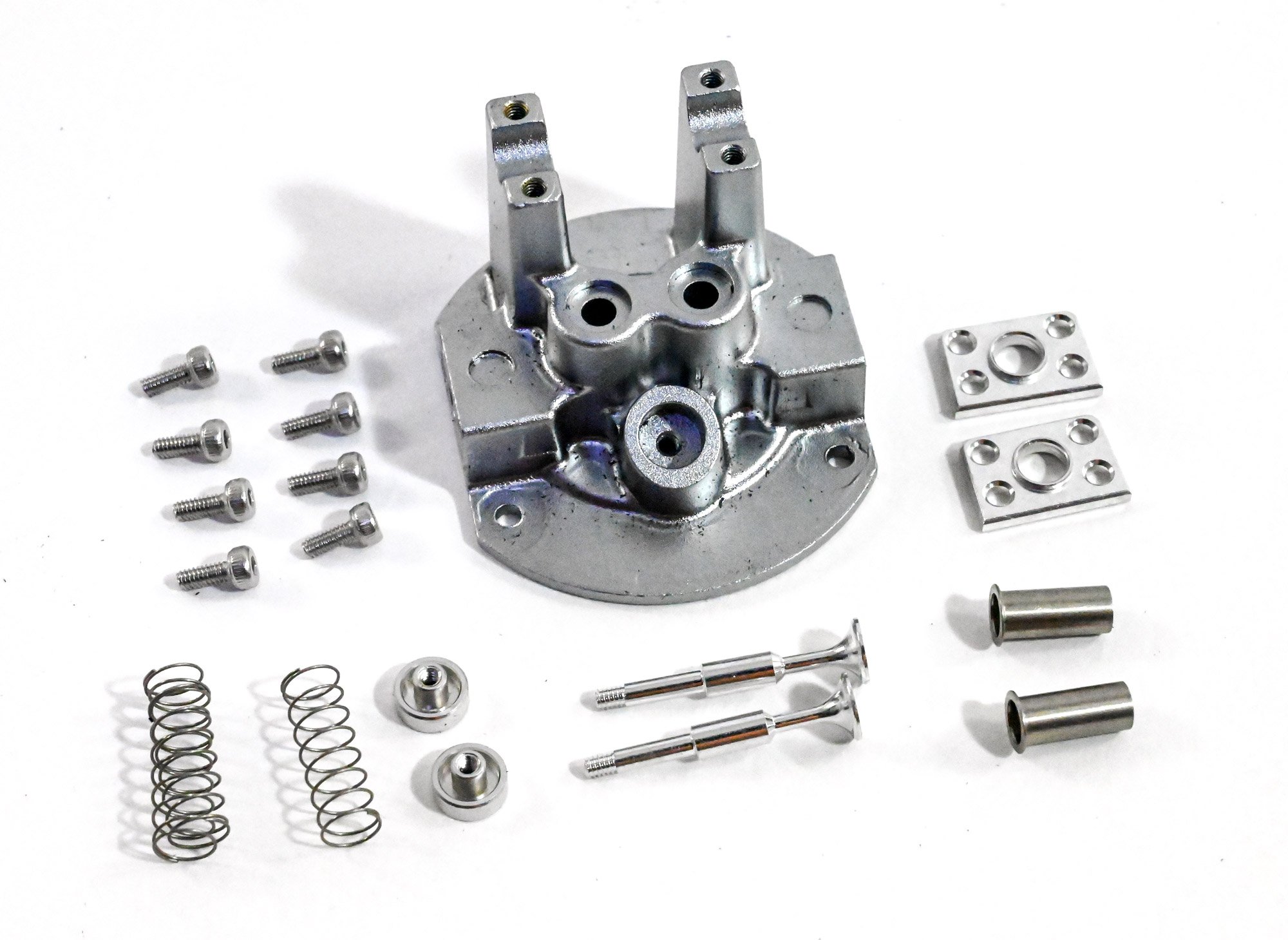
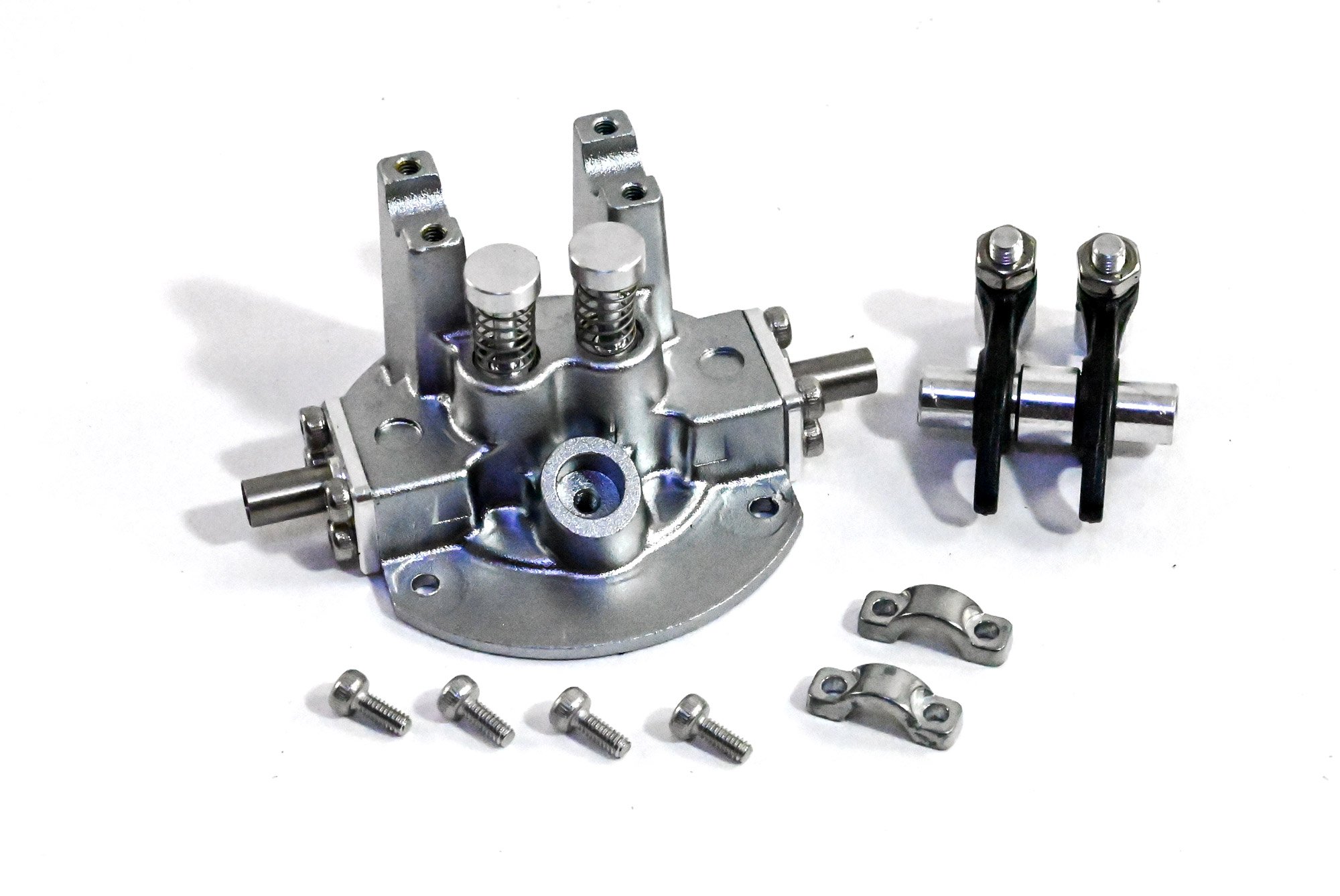
Now it's onto the rocker arm assemblies. It's here you'll find the only plastic parts of the engine, seen here in black. The quality is still excellent and these parts aren't at all fragile.
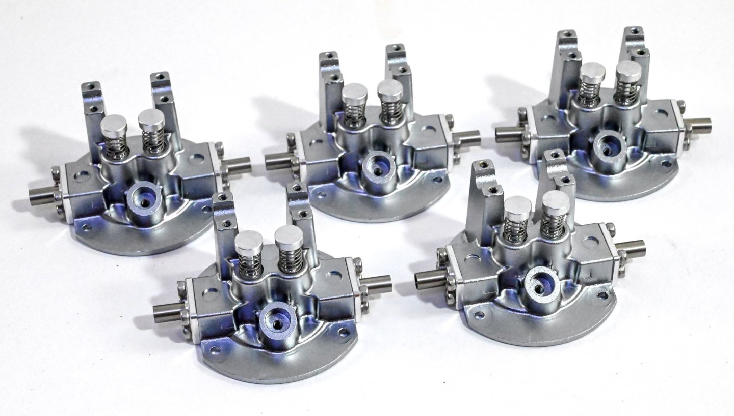
We turn our attention to the five cylinder head assemblies. Lots of screws to use here and you can see the exhaust ports and valves here. The valves do actually work too.

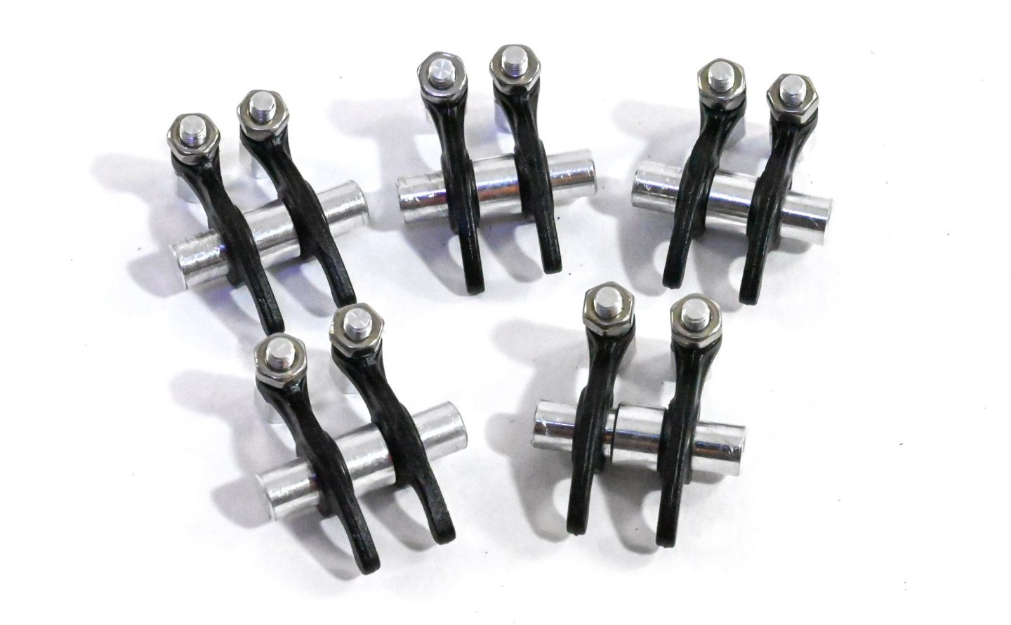
The rocker arms are now fitted to the top of the valve assemblies, and little reproduction spark plugs added. You could choose to paint the insulators in white, but I opted to leave in natural metal.

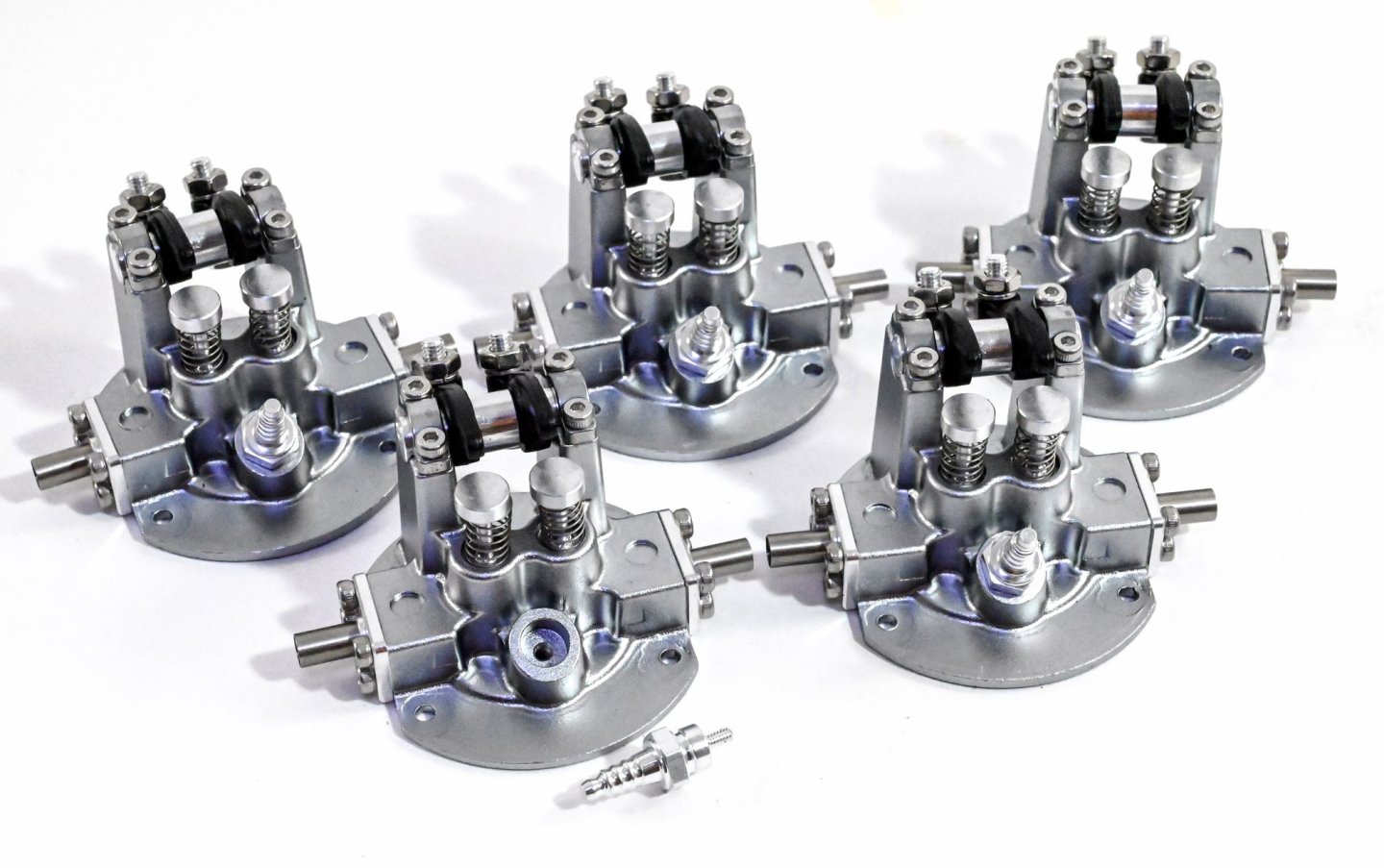
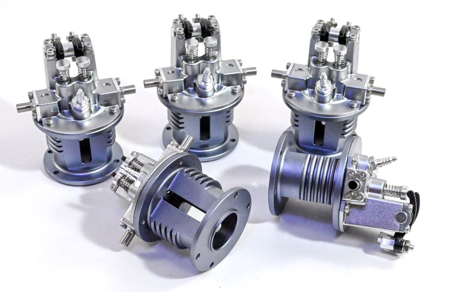
The cylinder blocks themselves are now fitted to the completed cylinder heads.
-
1
-
-
The lack of lube in the kit meant that I needed to buy some. I opted for this stuff, and used cotton buds to apply to the various connections. The manual us very clear about where lube is to be added, and this generally centres around the pistons and crankcase...not inside the piston heads.

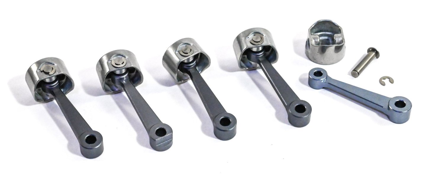
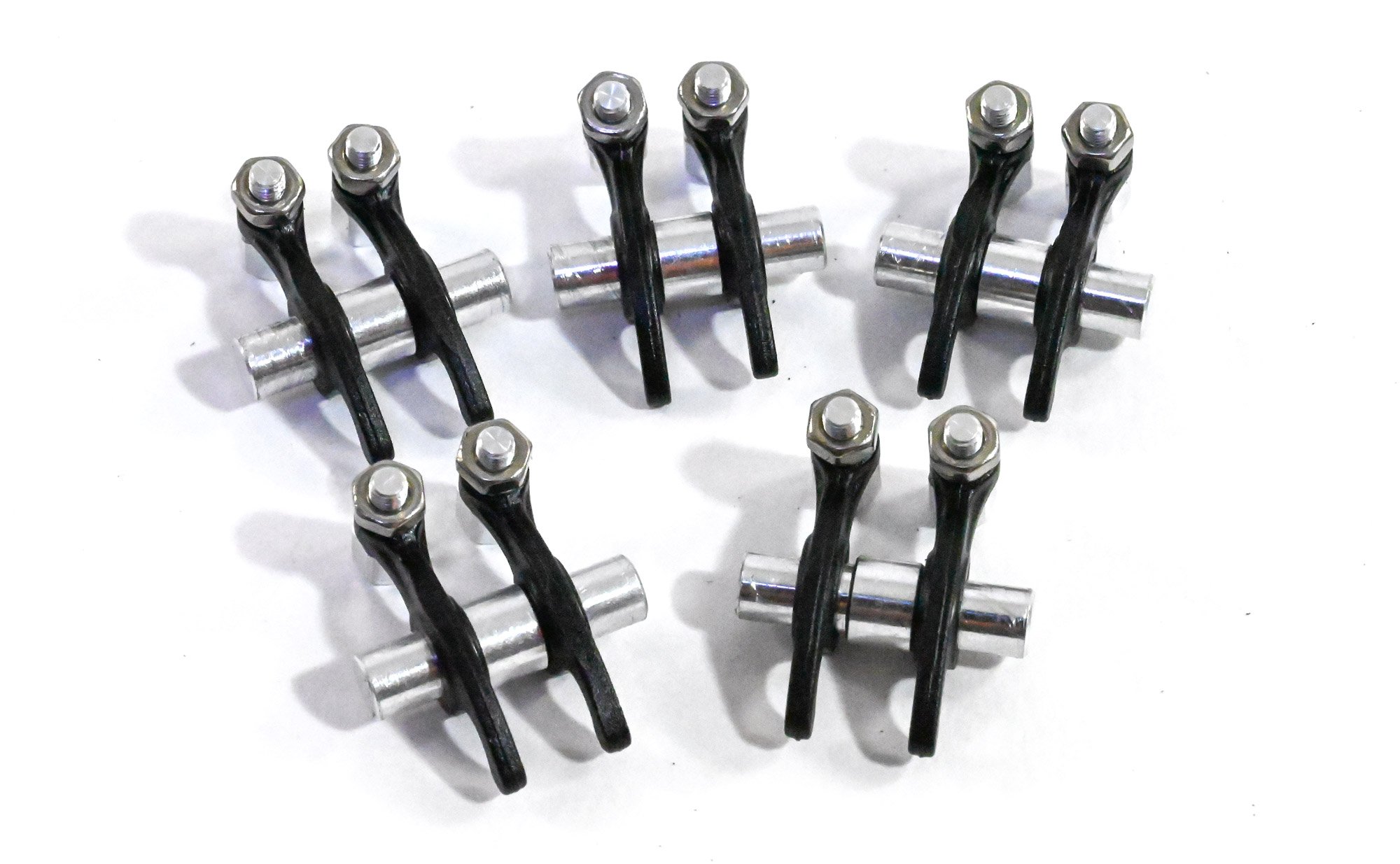
Piston assembly is very easy. All you need to do is to sit the linkages into the piston head and then insert a pin which is then locked into place by two circlips. As with the real engine, one of these has a master rod which connects to the crankshaft and does NOT articulate. Here, that is the second from the left. You can see a section machined out of the base which then is pinned to the crankshaft. The others will articulate.
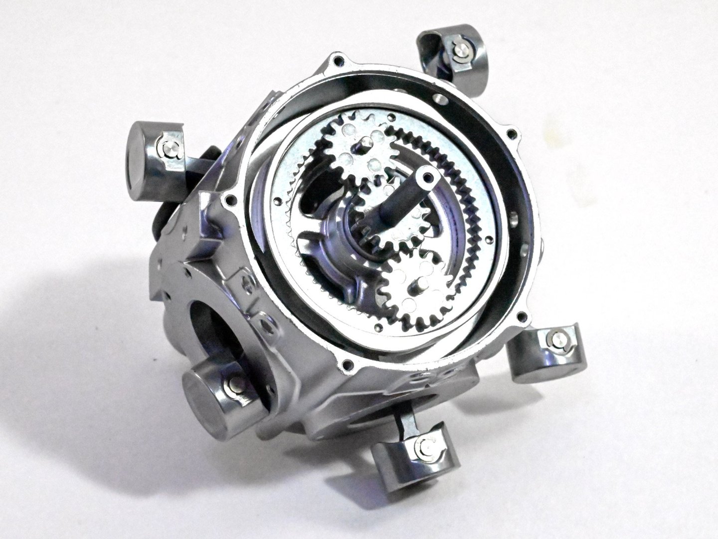
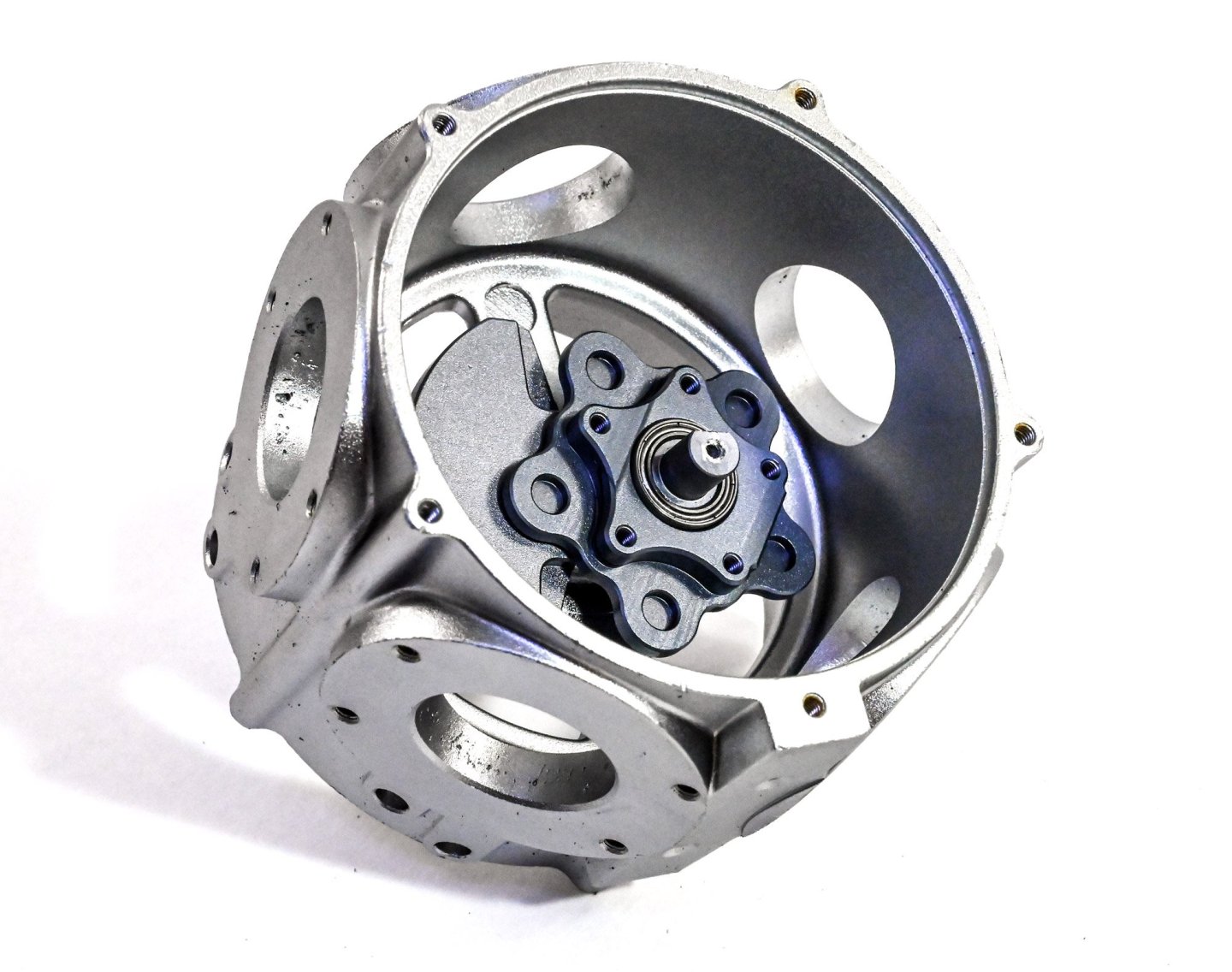
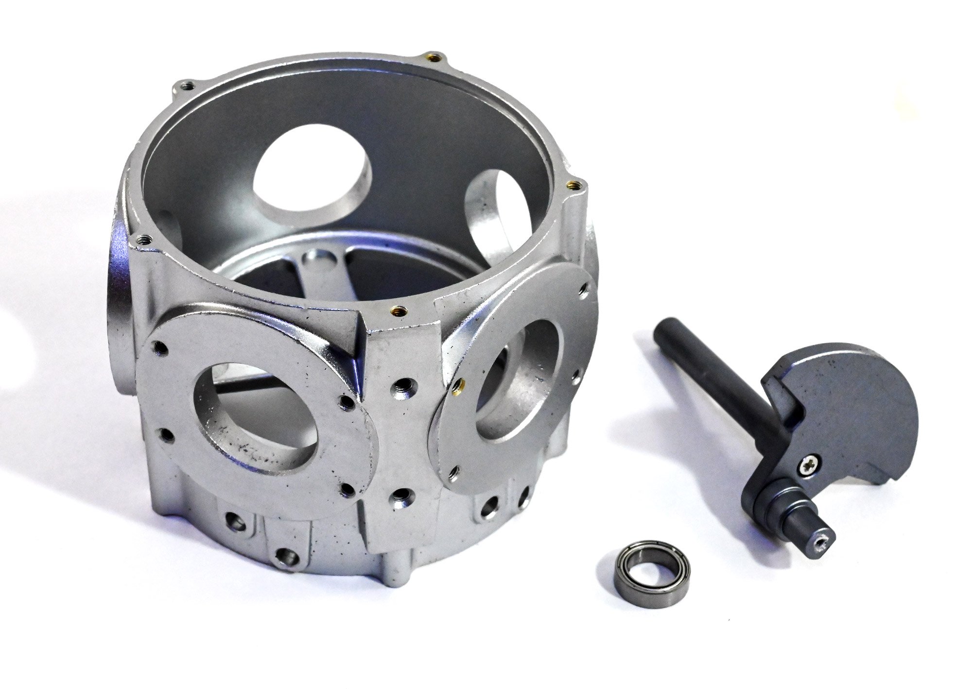
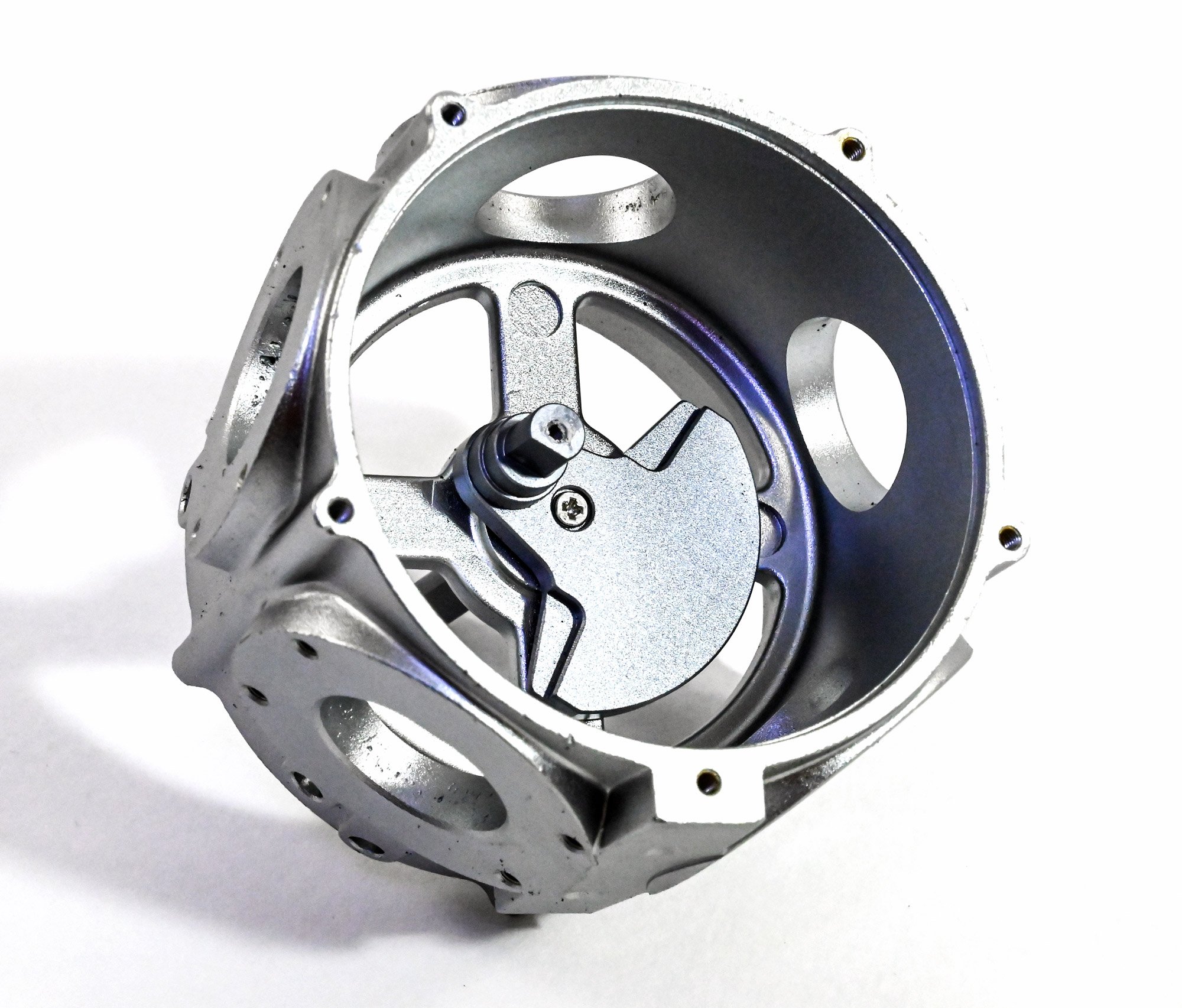
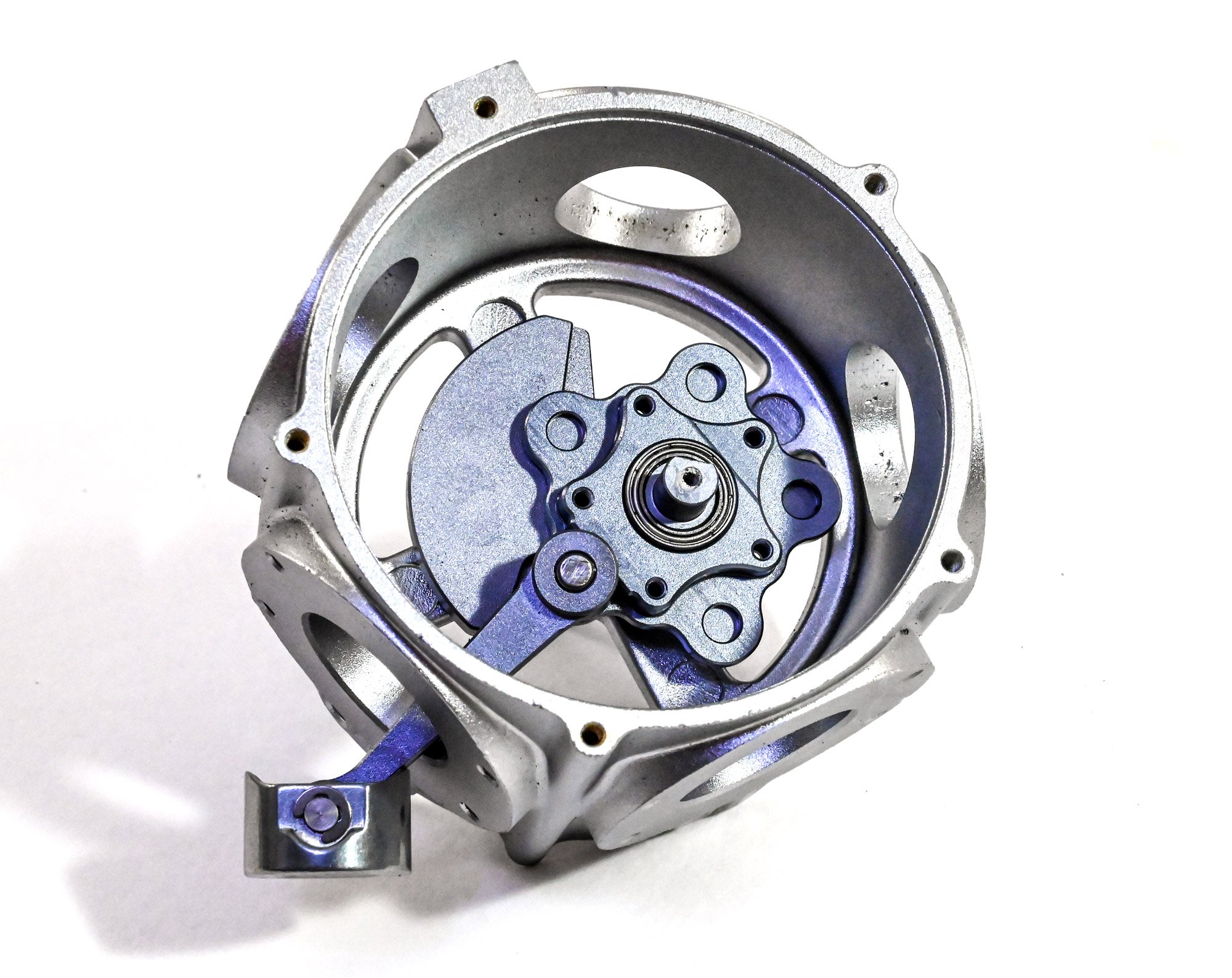
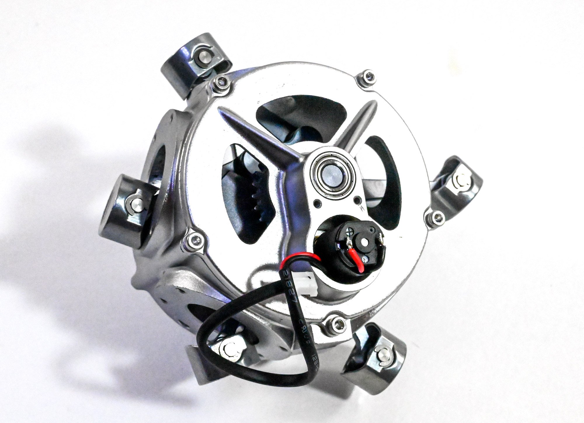
The crankshaft now sits within the crankcase. I add a little lube to this.

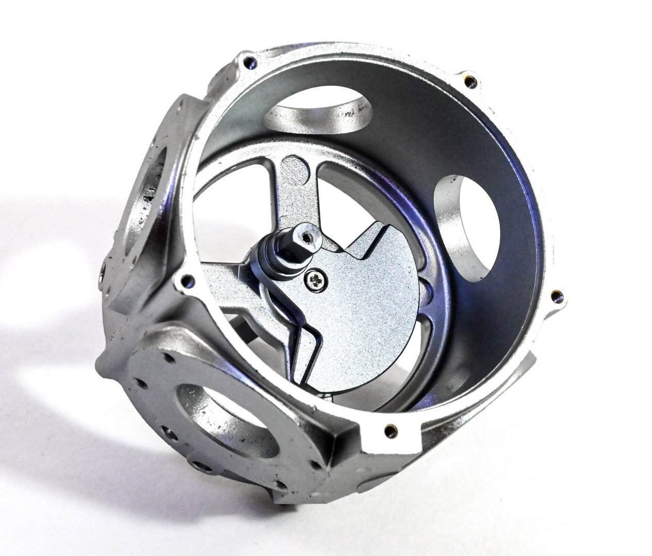
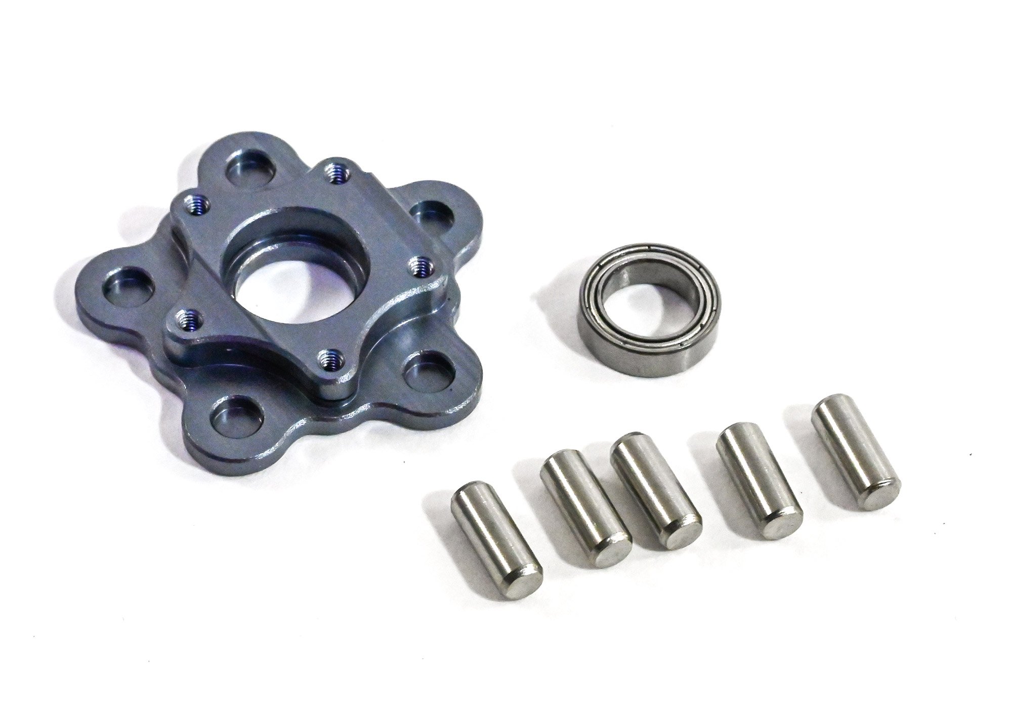
This part is then added to the crankshaft and provides the base onto which the pistons will fit. This is supplied with a small bearing that neatly pushes into it before assembly. The pins you see are for locating the pistons into the recesses in the assembly.

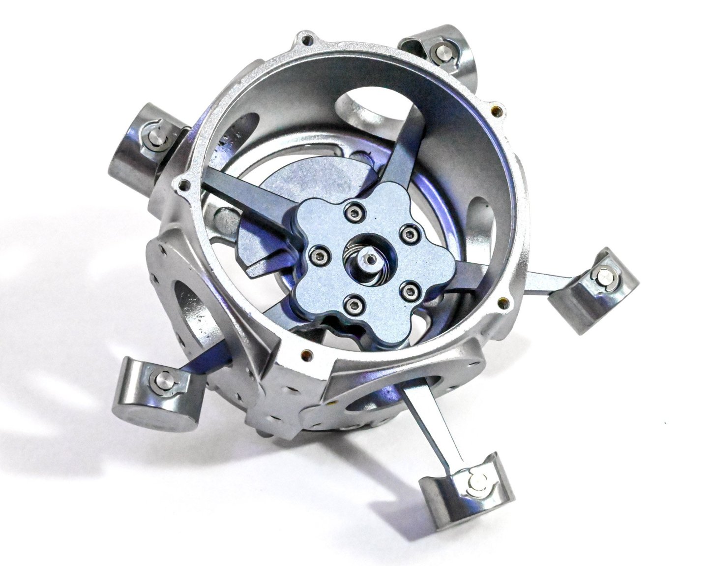
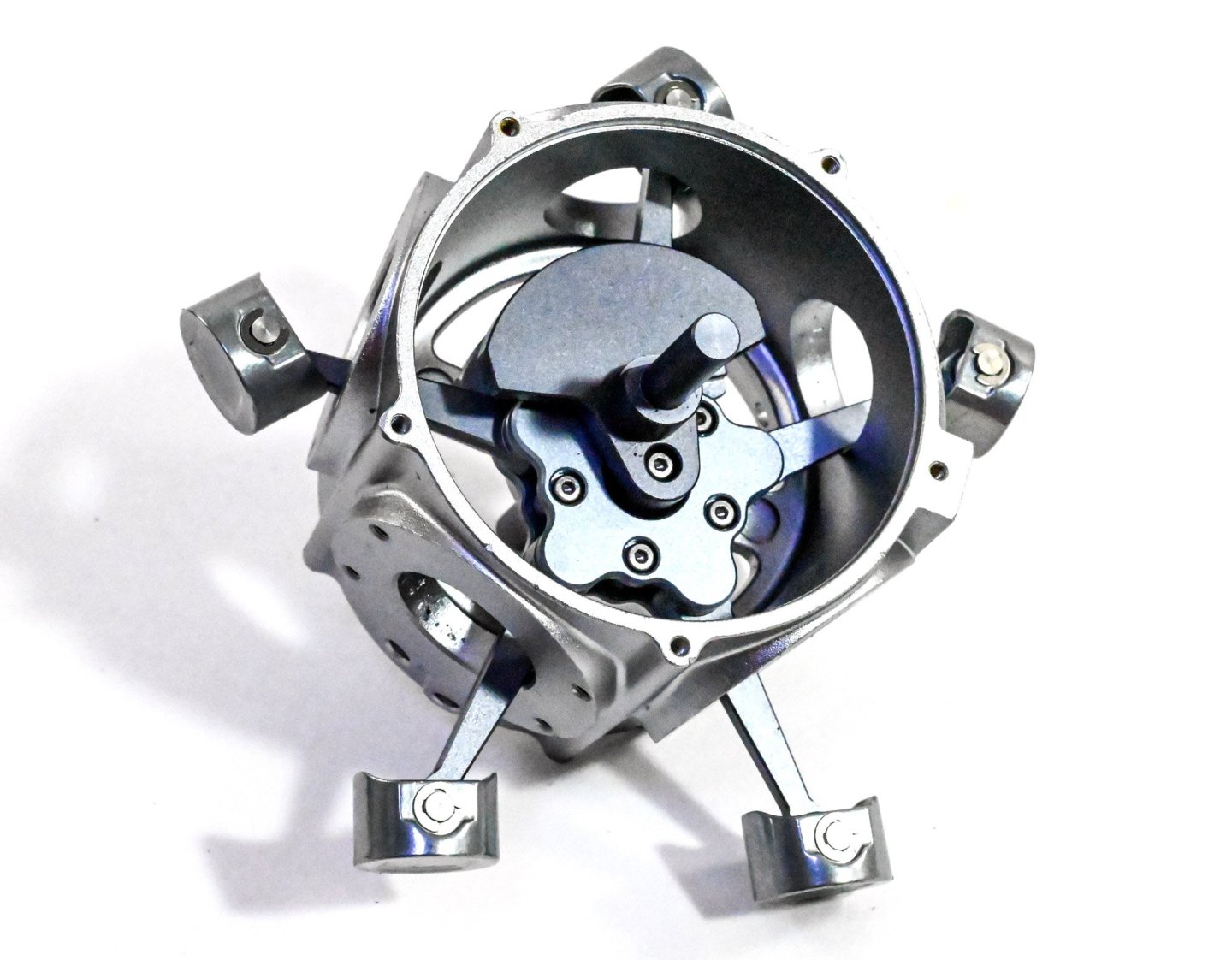
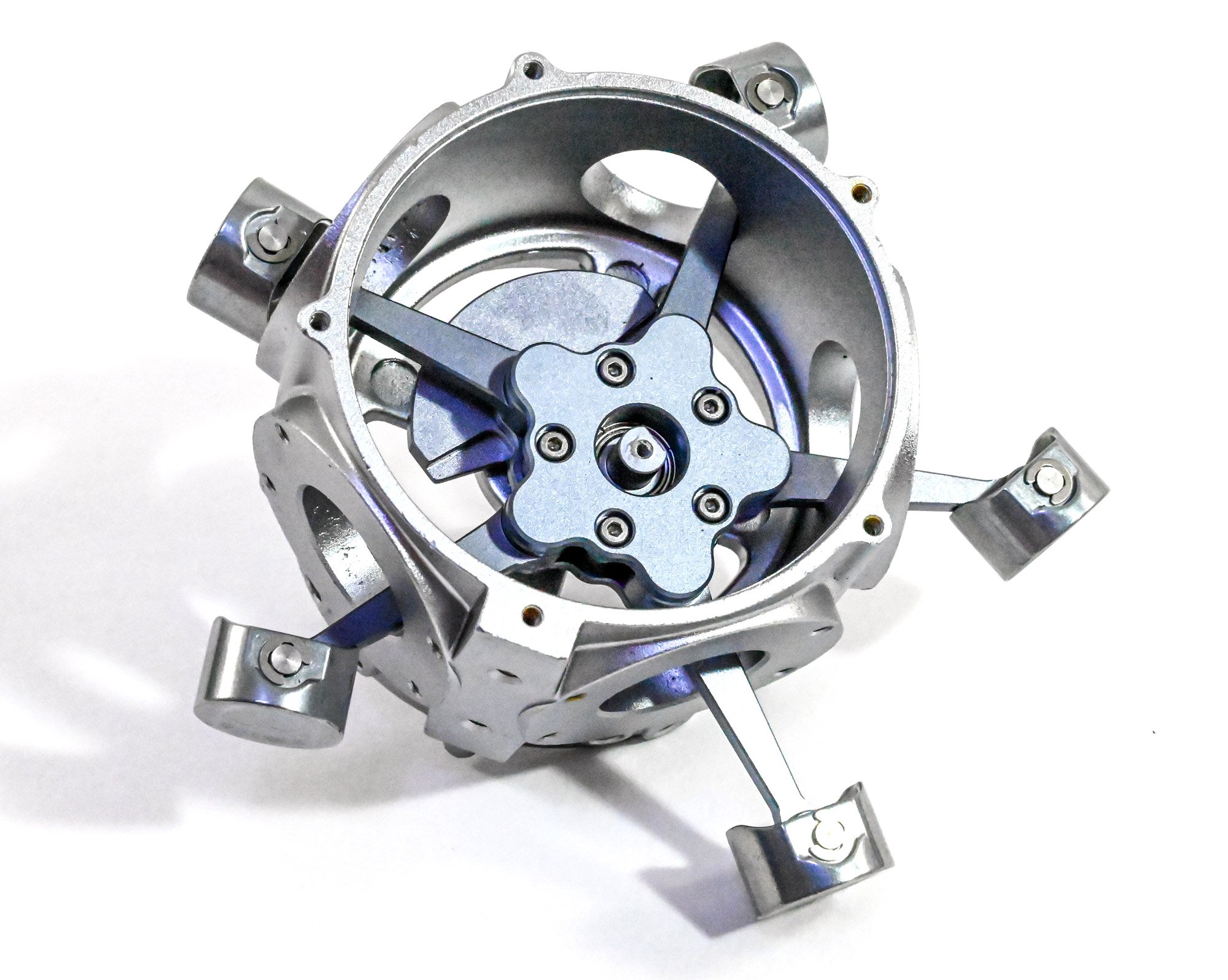
There is one task in assembling this engine, that could drive you to distraction, and that's adding the pistons. Without a doubt, this is awkward as there are five of these which will persistently try to fall out as you add the next. The best way to do this is to sit the crankcase into one of the cutouts in the foam parts tray and then carefully prop up each of the piston heads so they don't fall away from the centre of the crankcase. When you have them all in position, you can then add the linkage cap and screw it into position. This stage feels like a real achievement.

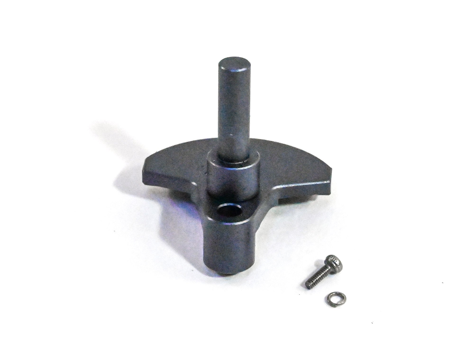
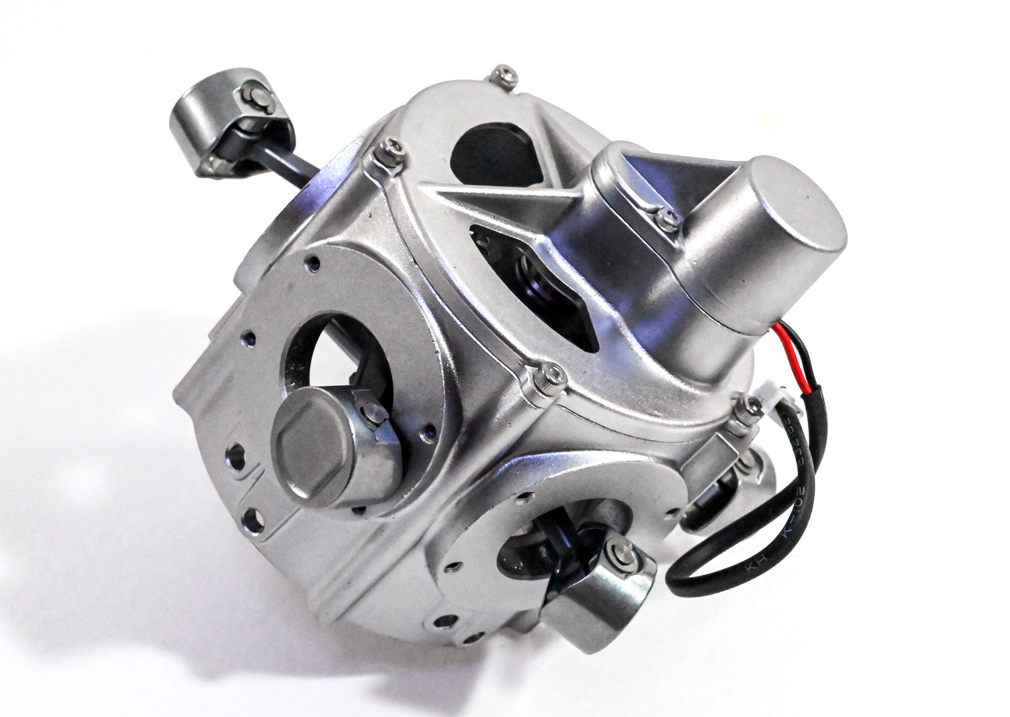
This crank can now be fitted into place.

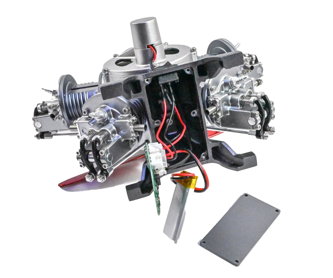
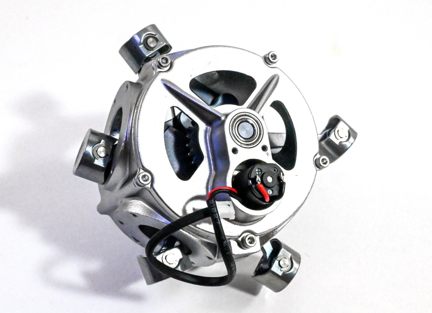
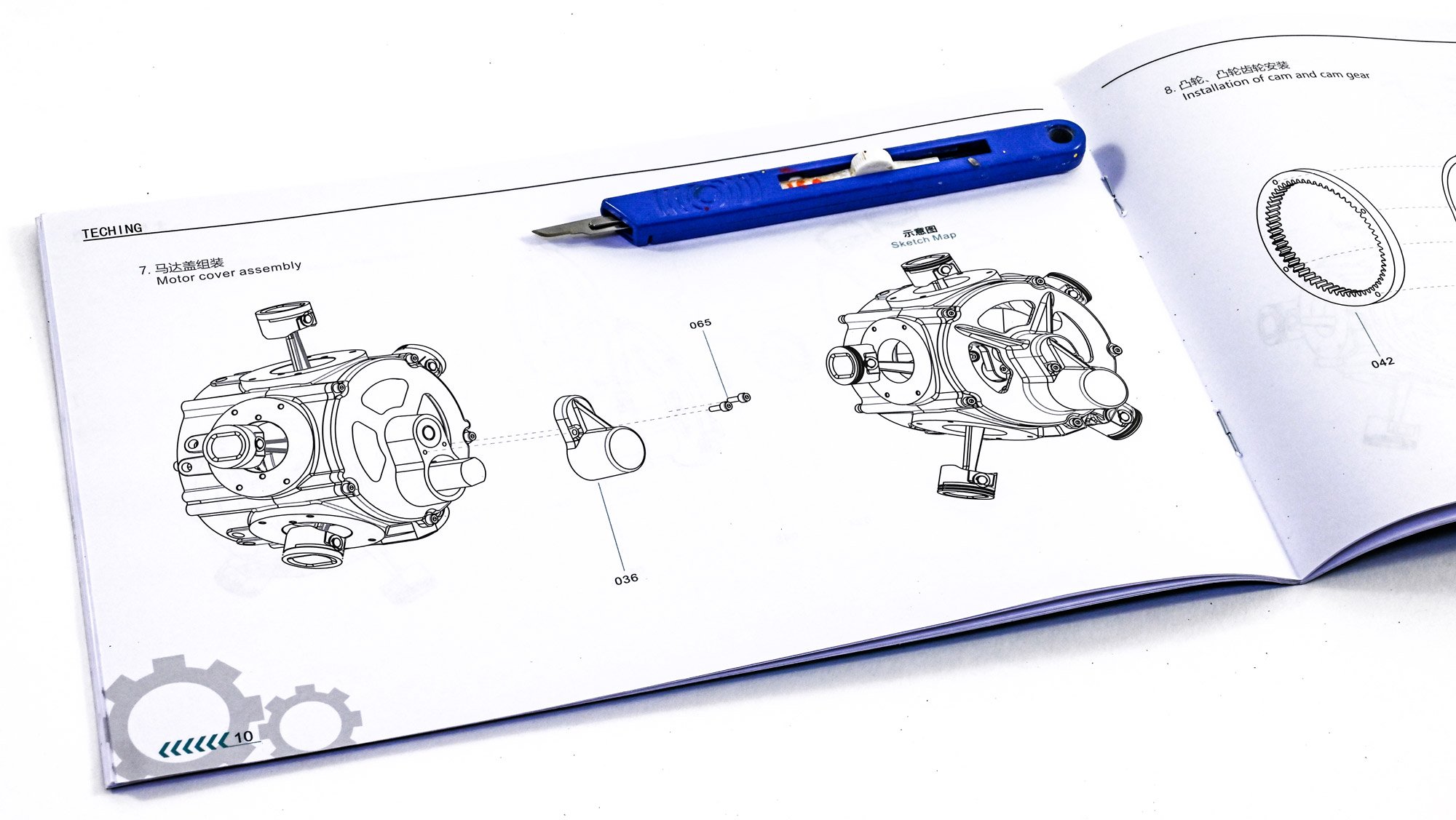
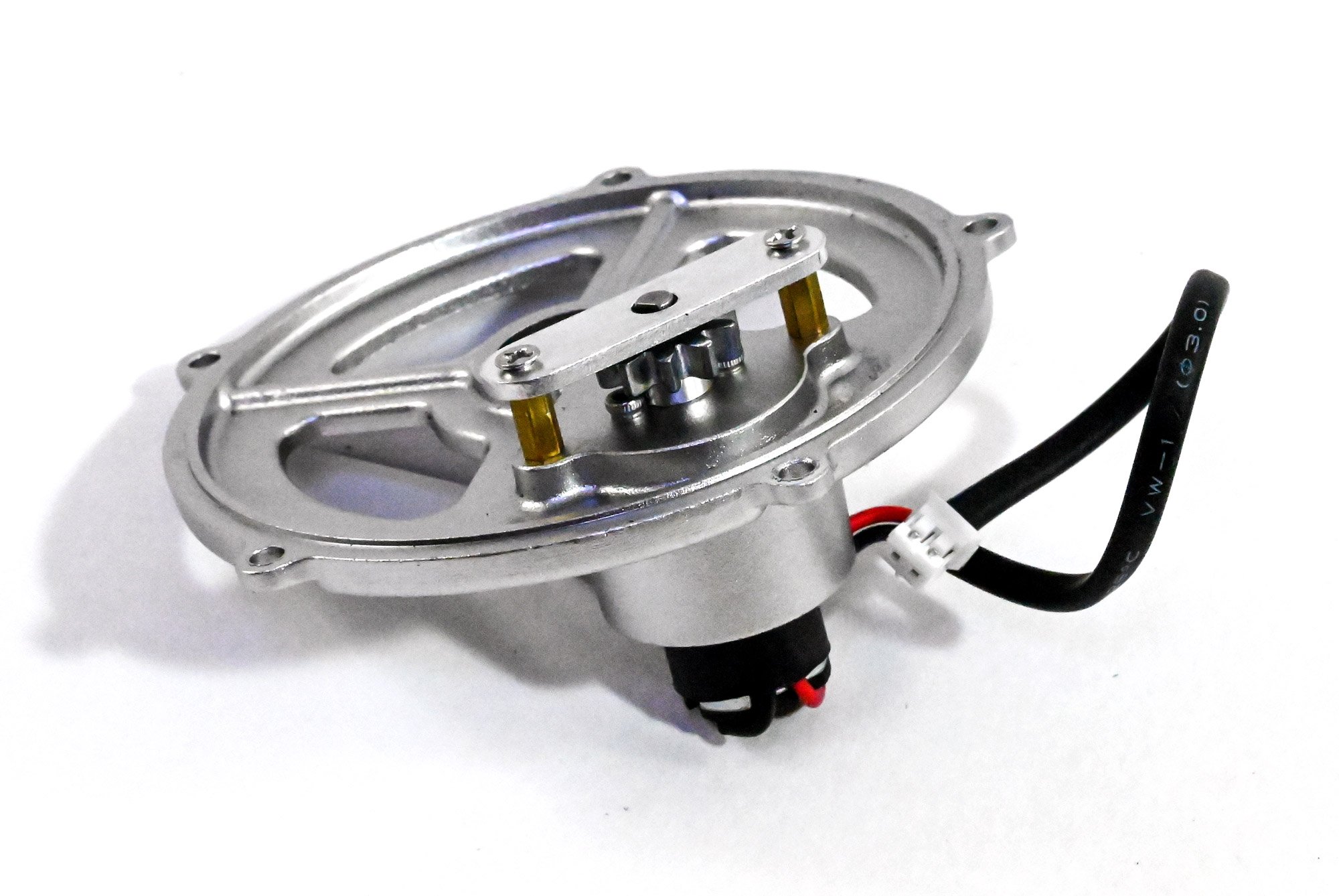
This is a working model, so a little cheat needs to be fitted, in the shape of an electric motor which will drive the gearing. This is also very nicely hidden when complete.
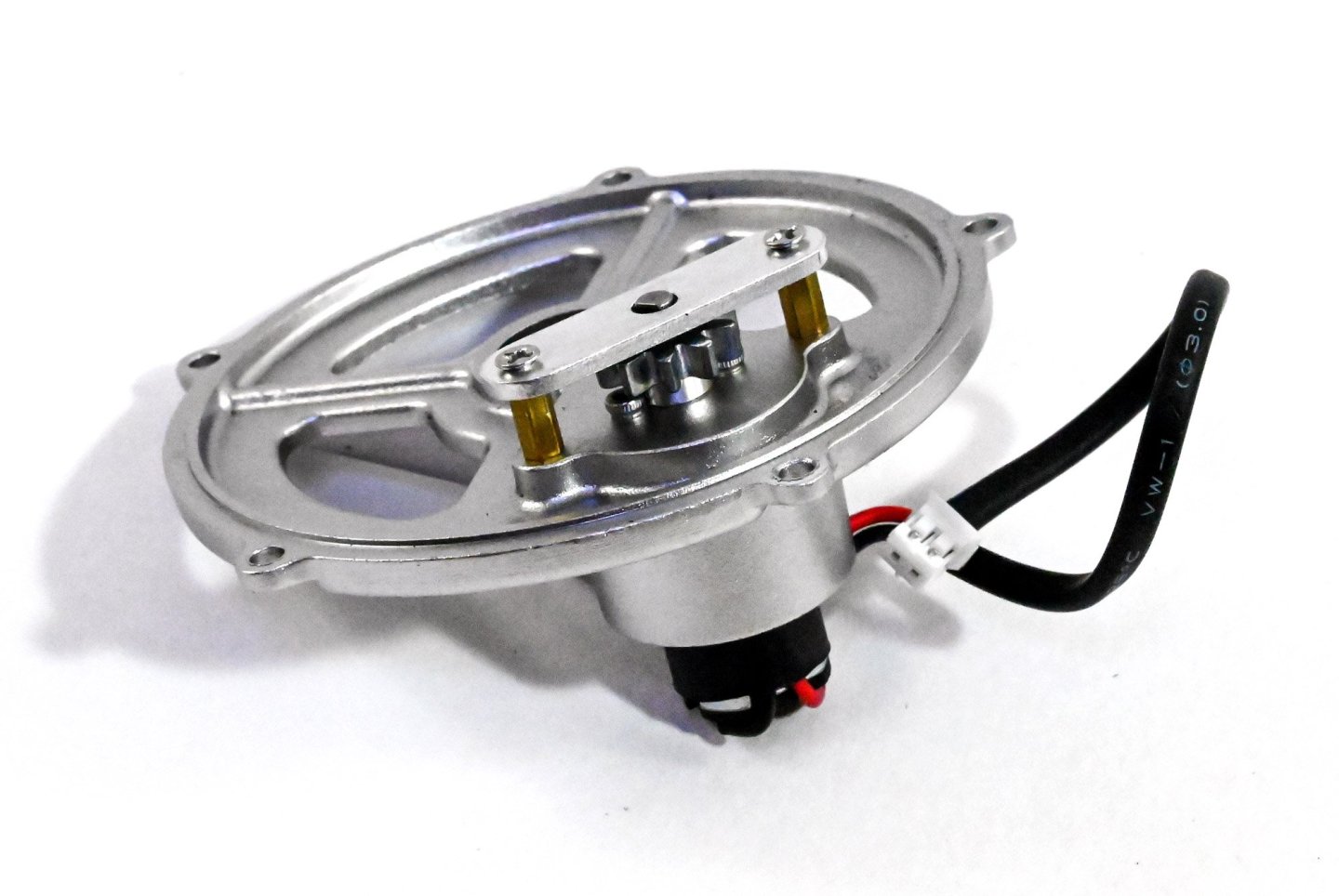

The completed rear crankcase now now be screwed to the main casing. One thing the manual does not make clear is that the motor needs to be adjacent to the stand connection on the main crankcase. I did fathom that out, but I have seen at least one video where a builder has a wire stretched around the back of the crankcase, down to the stand which contains the battery. The motor is then covered over.

-
1
-
-
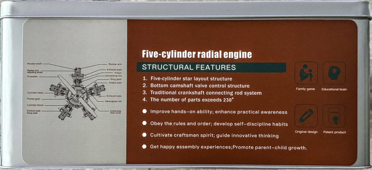
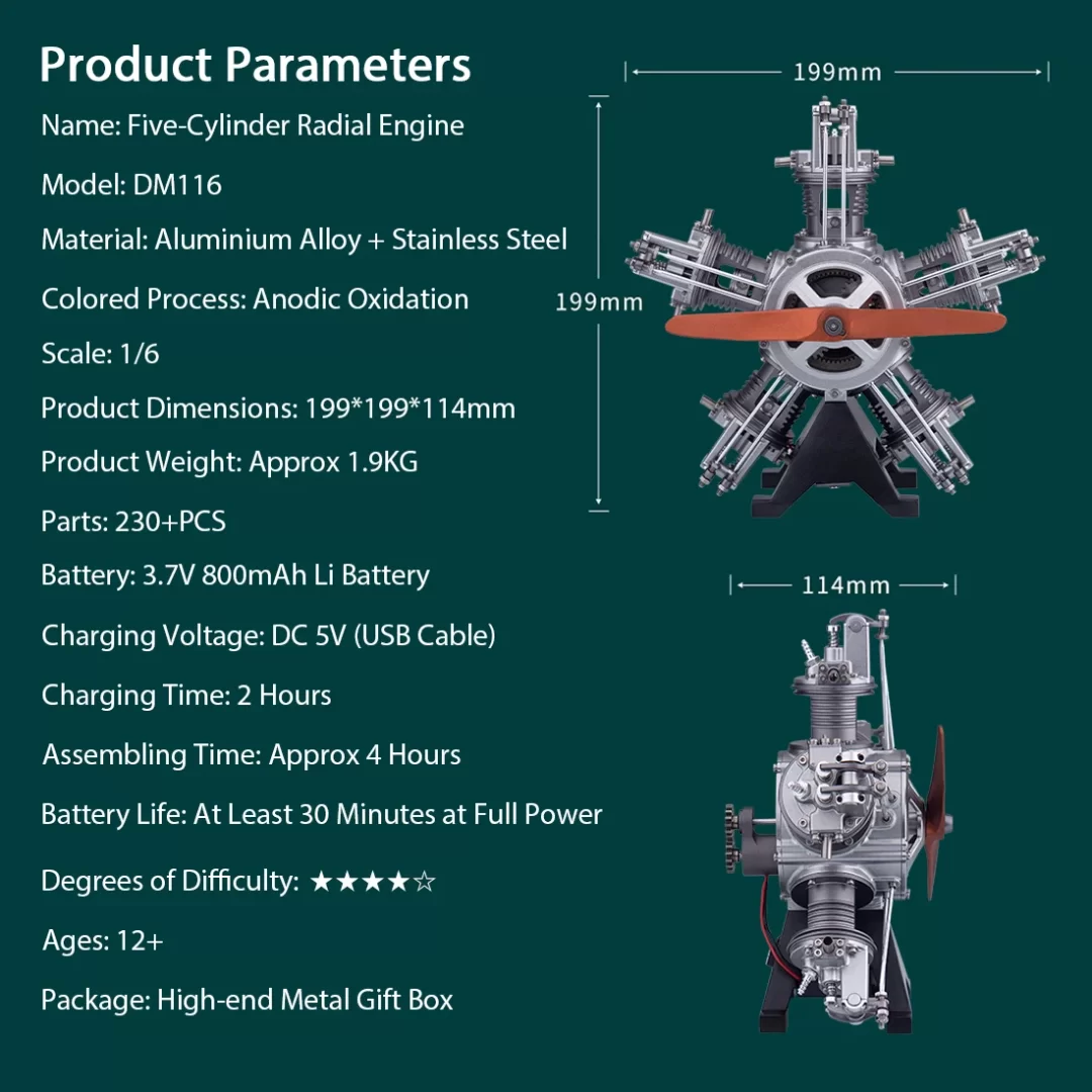
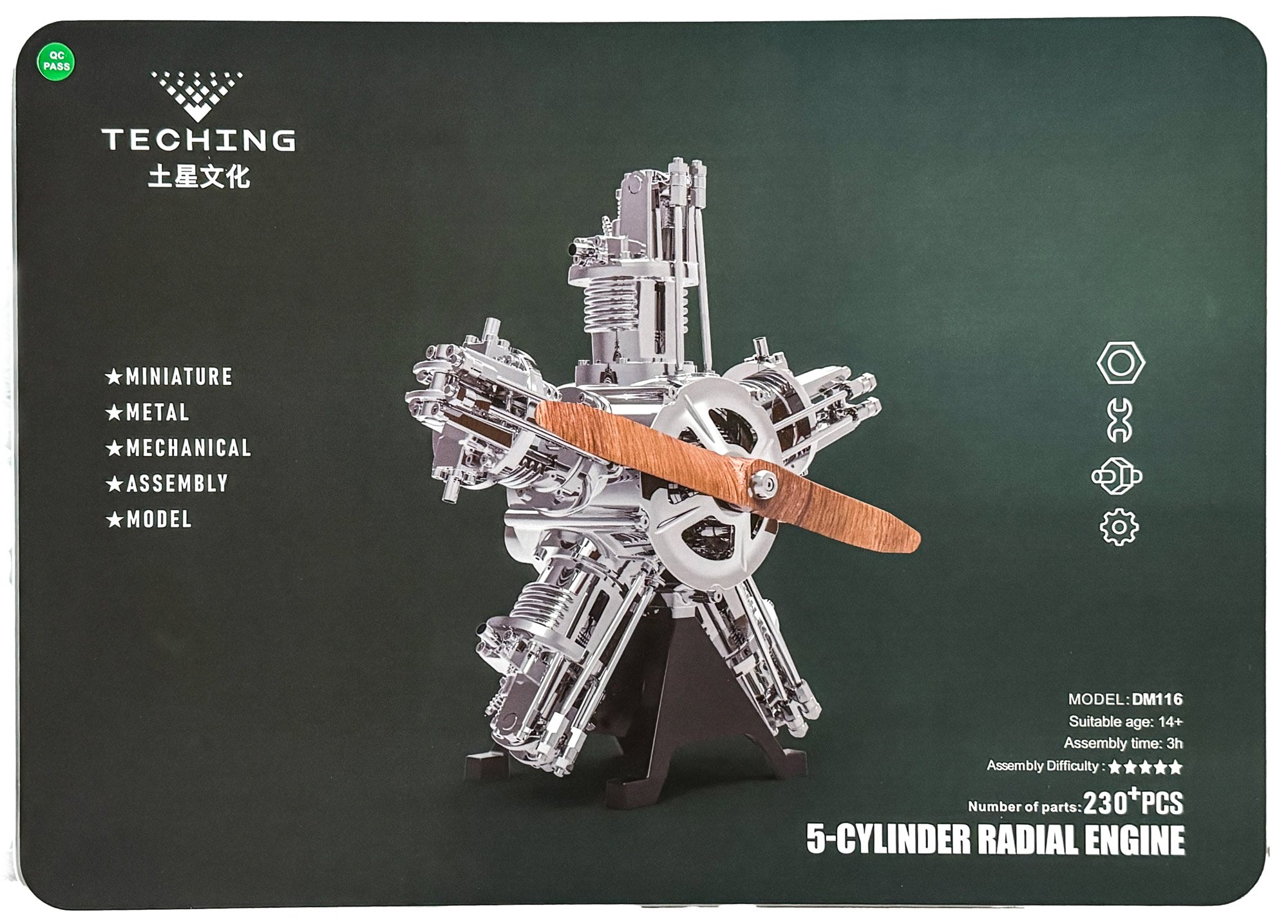
1:6 Five Cylinder Radial Engine (TECHING)
EngineDIY
Catalogue # 33ED3355414
Available from EngineDIY for $469.99

C. M. Manly constructed a water-cooled five-cylinder radial engine in 1901, a conversion of one of Stephen Balzer's rotary engines, for Langley's Aerodrome aircraft. Manly's engine produced 52 hp (39 kW) at 950 rpm. Most radial engines are air-cooled, but one of the most successful of the early radial engines (and the earliest "stationary" design produced for World War I combat aircraft) was the Salmson 9Z series of nine-cylinder water-cooled radial engines that were produced in large numbers. Georges Canton and Pierre Unné patented the original engine design in 1909, offering it to the Salmson company; the engine was often known as the Canton-Unné.
The radial engine is a reciprocating type internal combustion engine configuration in which the cylinders"radiate" outward from a central crankcase like the spokes of a wheel. The pistons are connected to the crankshaft with a master-and-articulating-rod assembly. One piston, the uppermost one in the animation, has a master rod with a direct attachment to the crankshaft. The remaining pistons pin their connecting rods' attachments to rings around the edge of the master rod. Extra "rows" of radial cylinders can be added in order to increase the capacity of the engine without adding to its diameter.
The kit

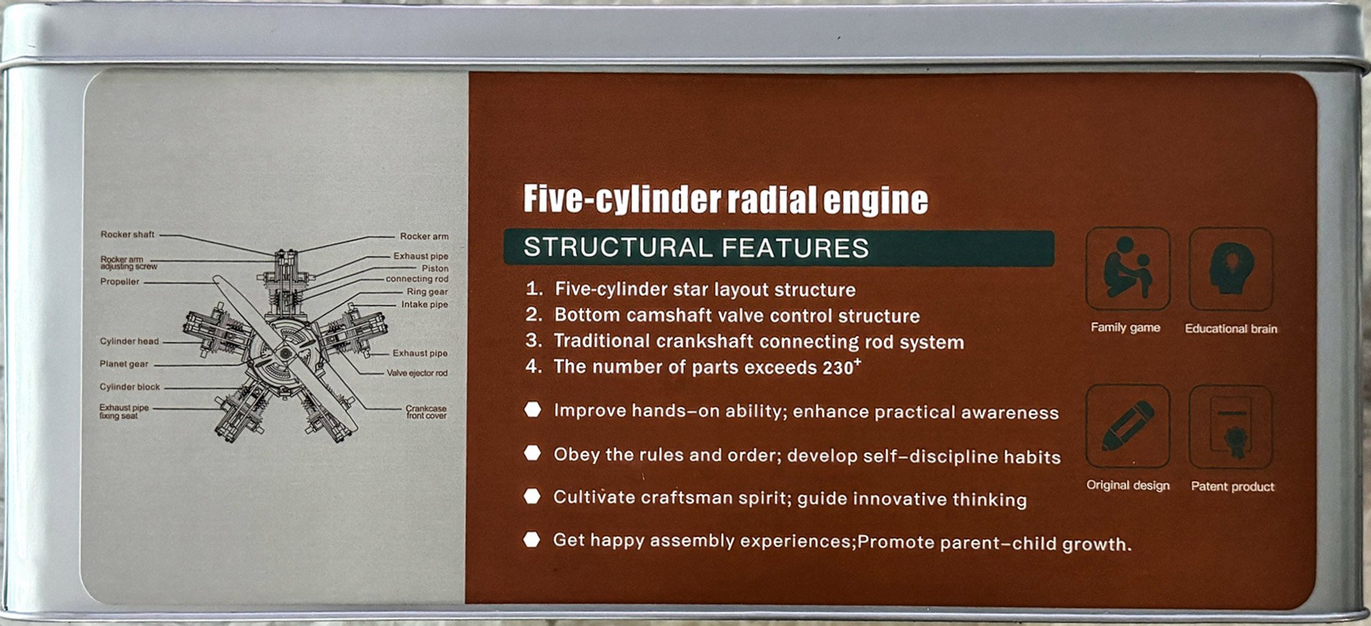
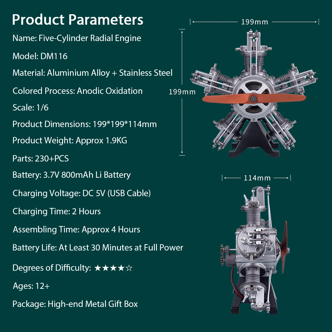
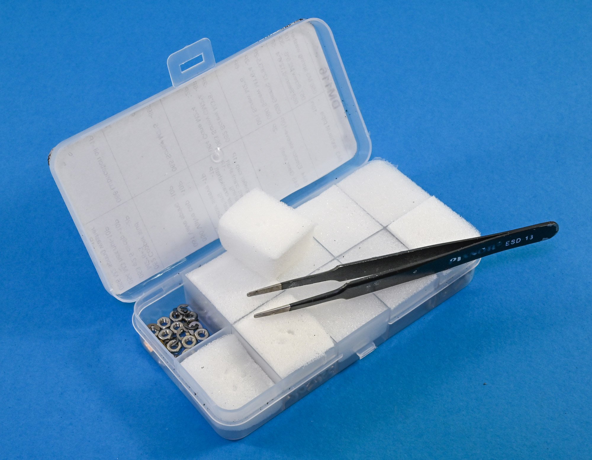
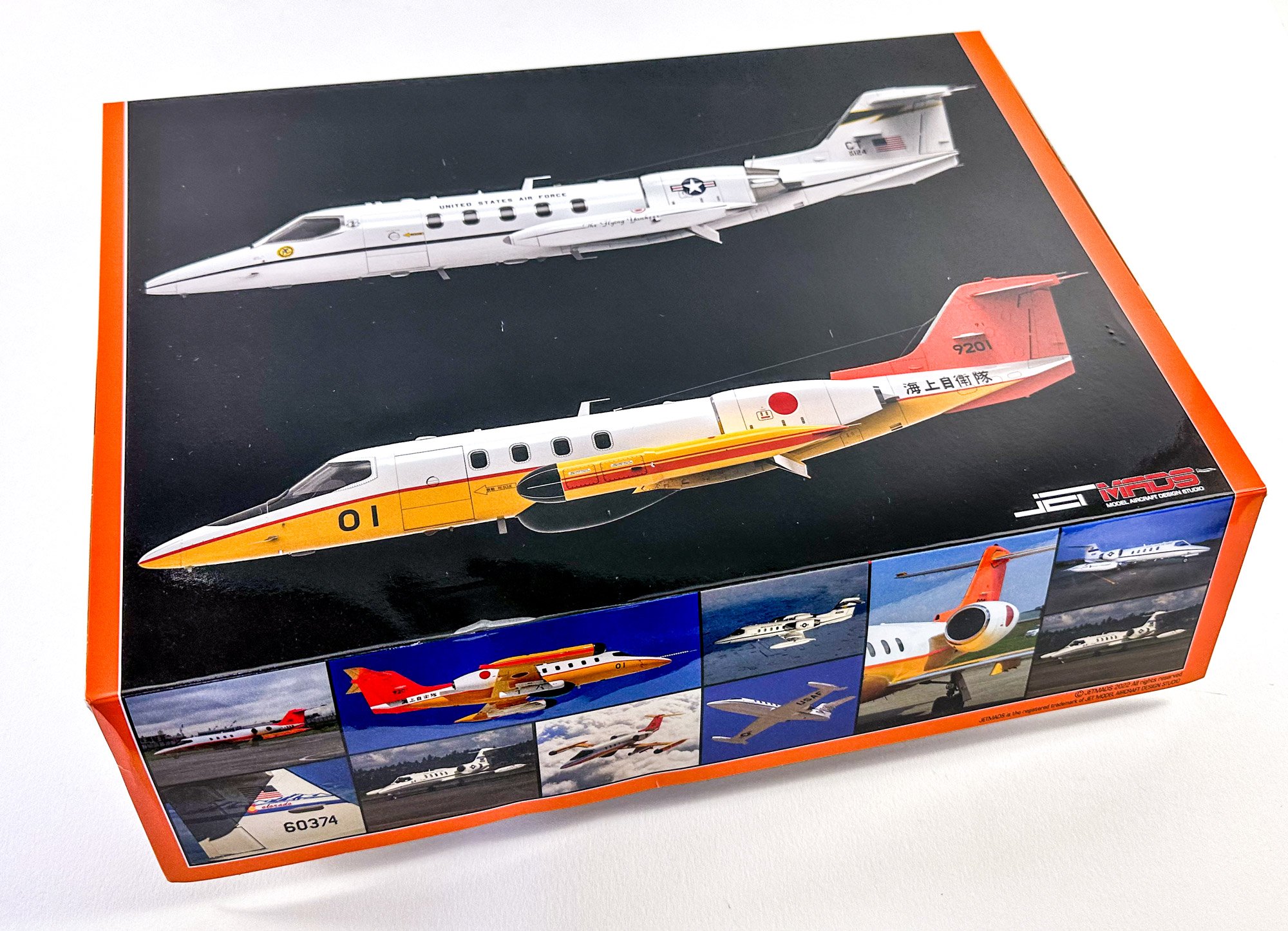
A 1:6 engine comes in quite a large box, as I soon realised. Actually, it's a very high quality tin, with a lid that lifts right off to display an instruction manual sitting between two pieces of protective foam. The lid itself shows an illustration of the completed engine, while the side has the kit-specific details. For an idea of scale, I've sat my Swann Morton retractable scalpel on the kit. There's a reasonable amount of weight in this kit too...approximately between 1.5 and 2kg. No surprise as this kit is 99% metal. The side panel of the tin gives a few more details.


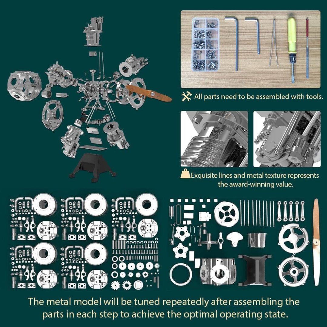
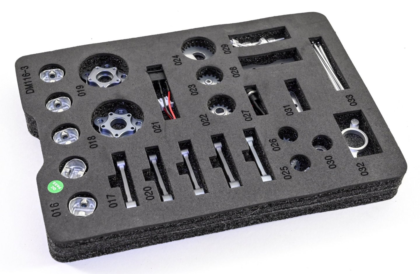
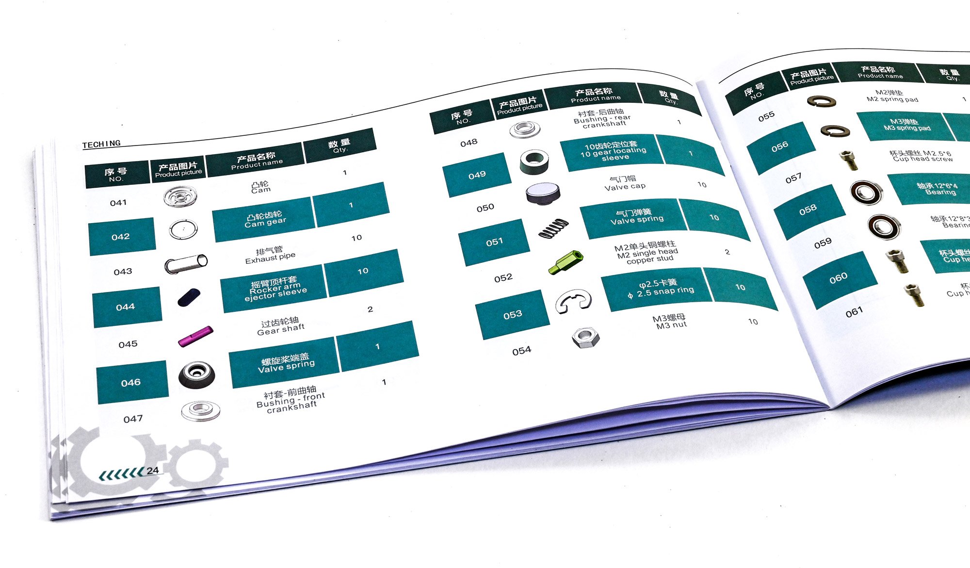
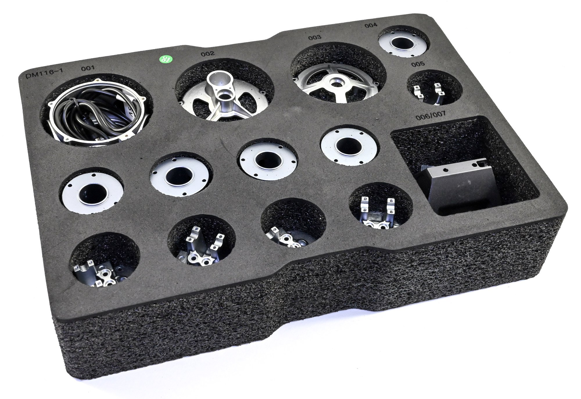
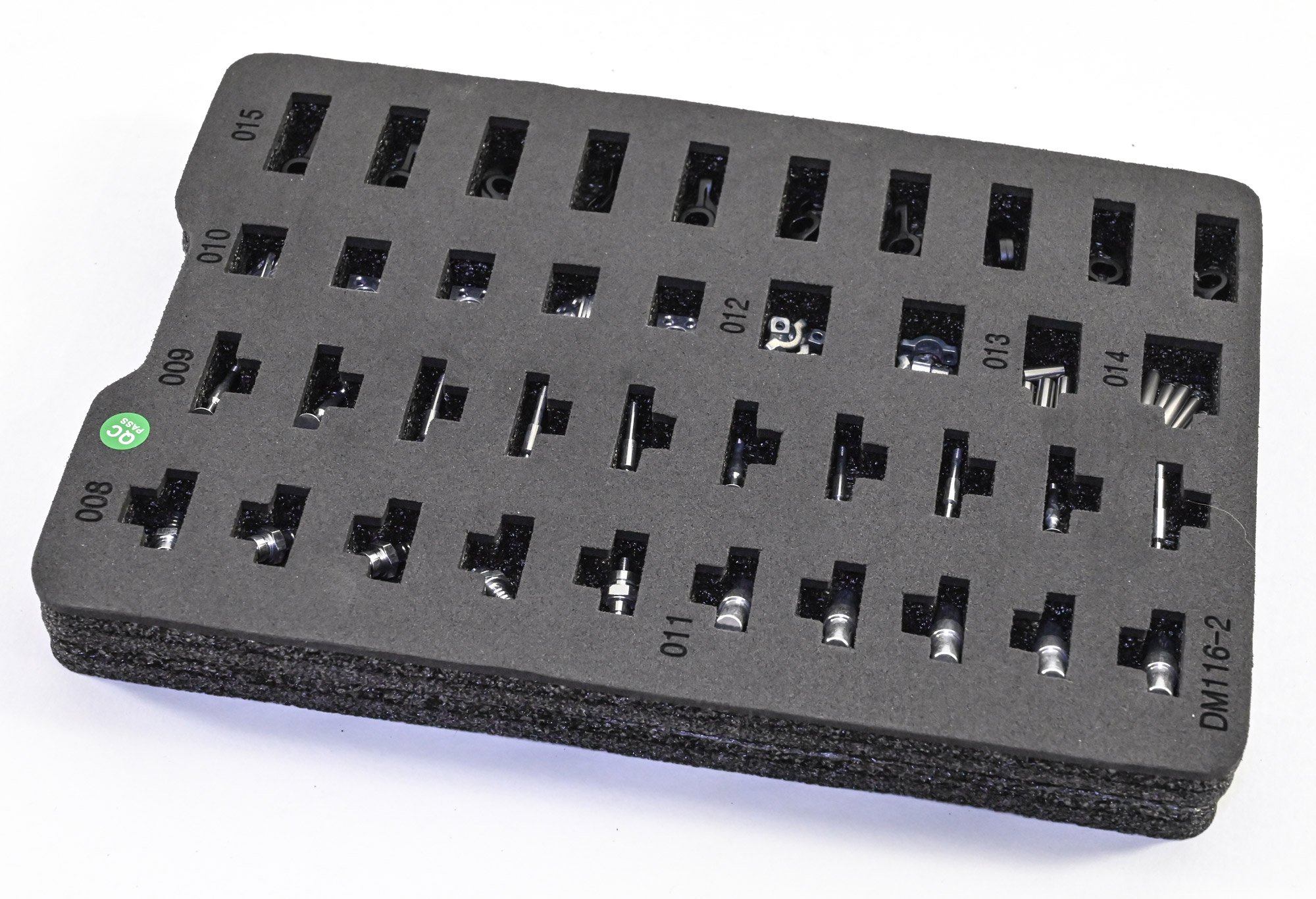
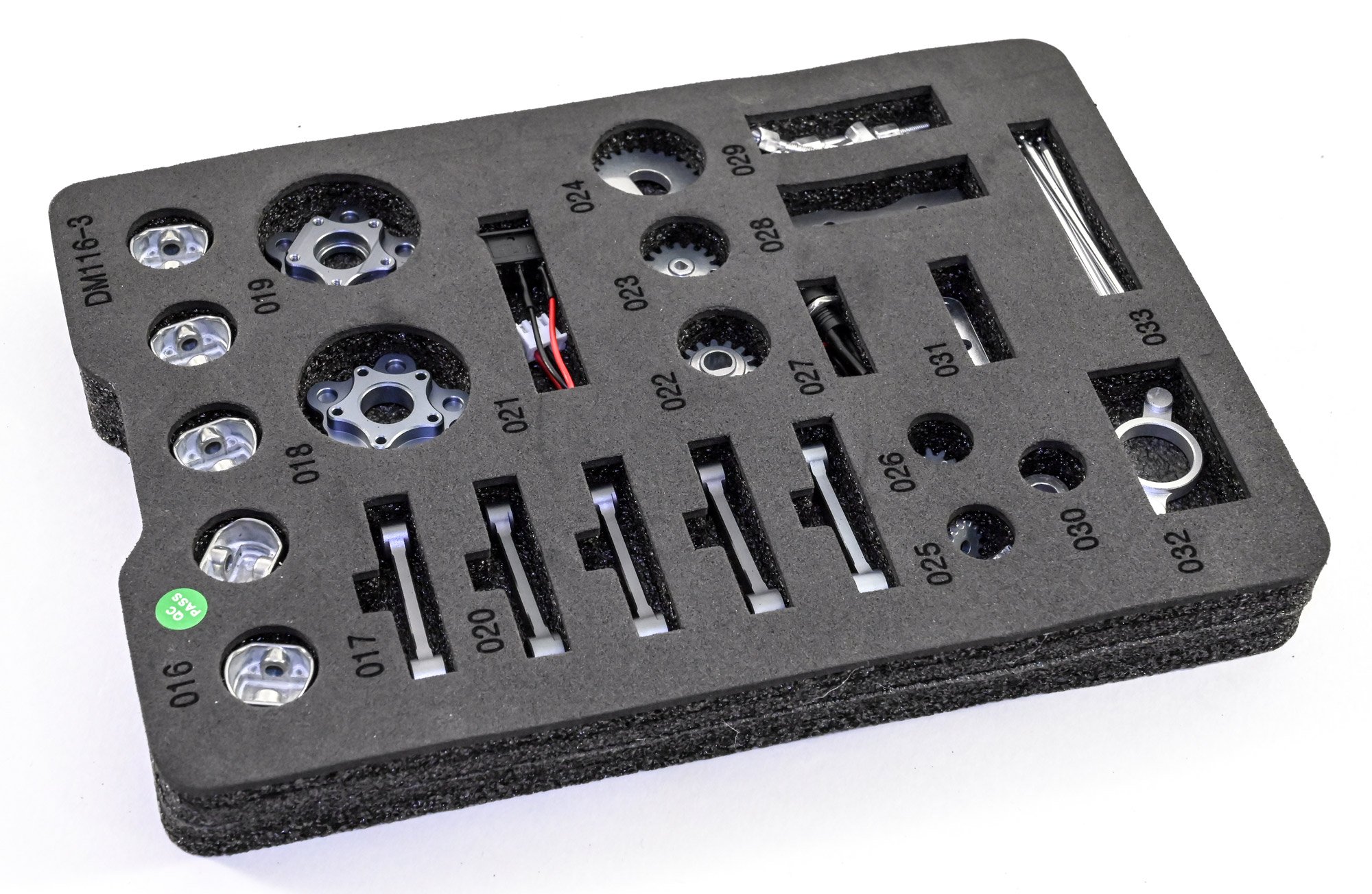
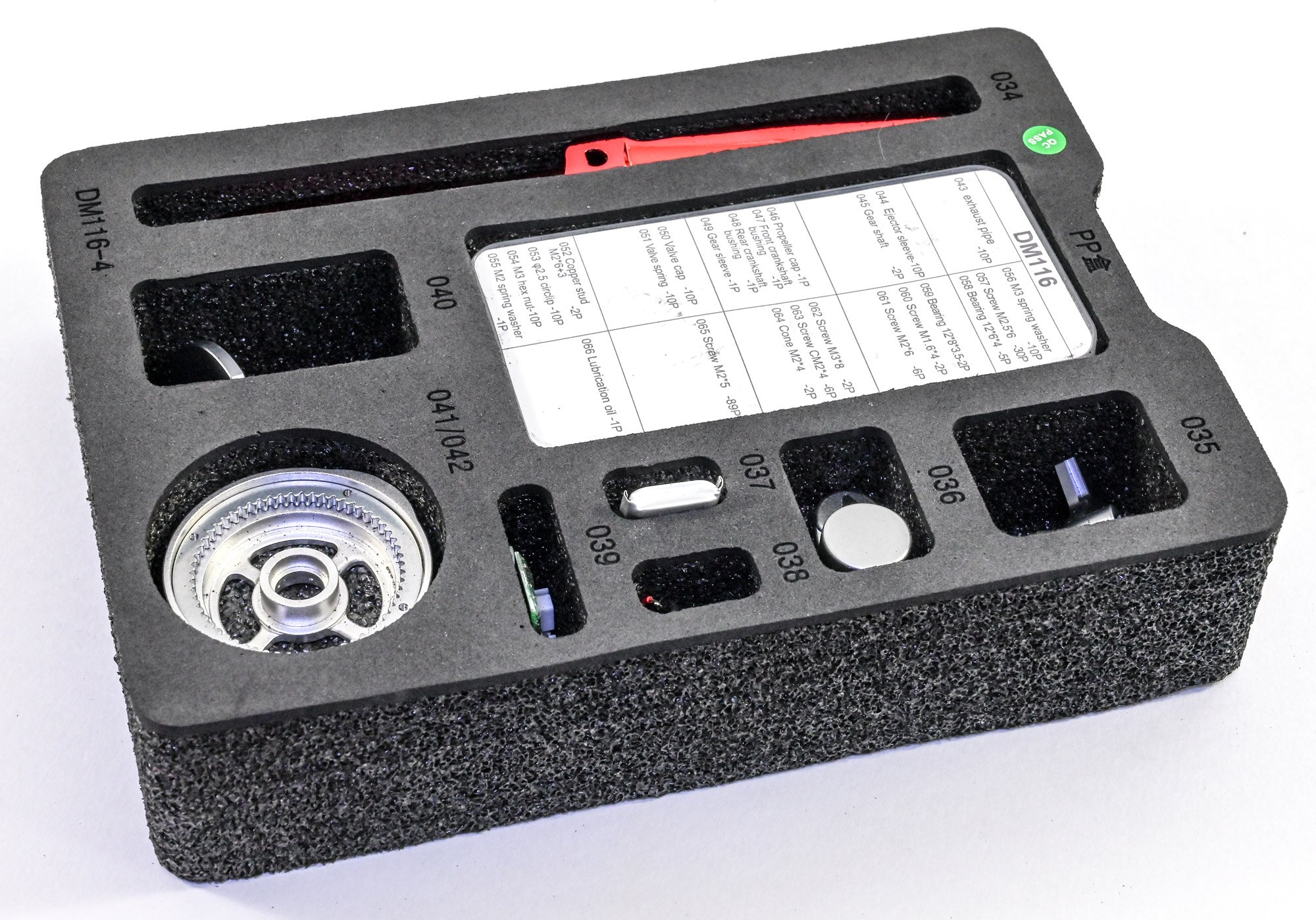
All of the parts in this kit are recessed within sturdy foam trays that also have the part numbers engraved into the foam, adjacent to each part. This makes it ridiculously easy to find exactly what you need in each stage. There are FOUR trays of components in this kit. While there are are a number of electronics parts, with the exception of these and the plastic cylinder head rockers, everything is in cast or machined aluminium etc.


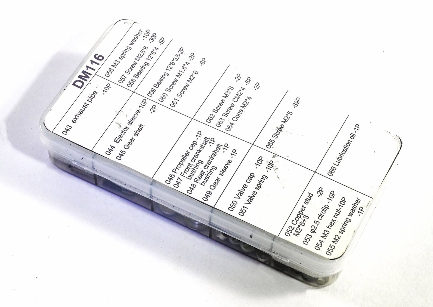
You'll notice the white plastic box in that tray. That's choc-full of screws, turned parts, springs, bearings etc. Each little section is padded with some foam. Again, there's no lube in this box. It must be something they had to leave out for some reason. Quite add as the kit contains another contentious item....a lithium battery.

-
-

Evening ladies,
I've not written a review for a very long time, and this isn't really one either as Ernie has said plenty on his review of this same kit, and I largely agree with his assessment. In fact, I'm probably happier about the engravings on the resin parts that he is. 😂
Here is a link to tie in Ernie's review into this article:
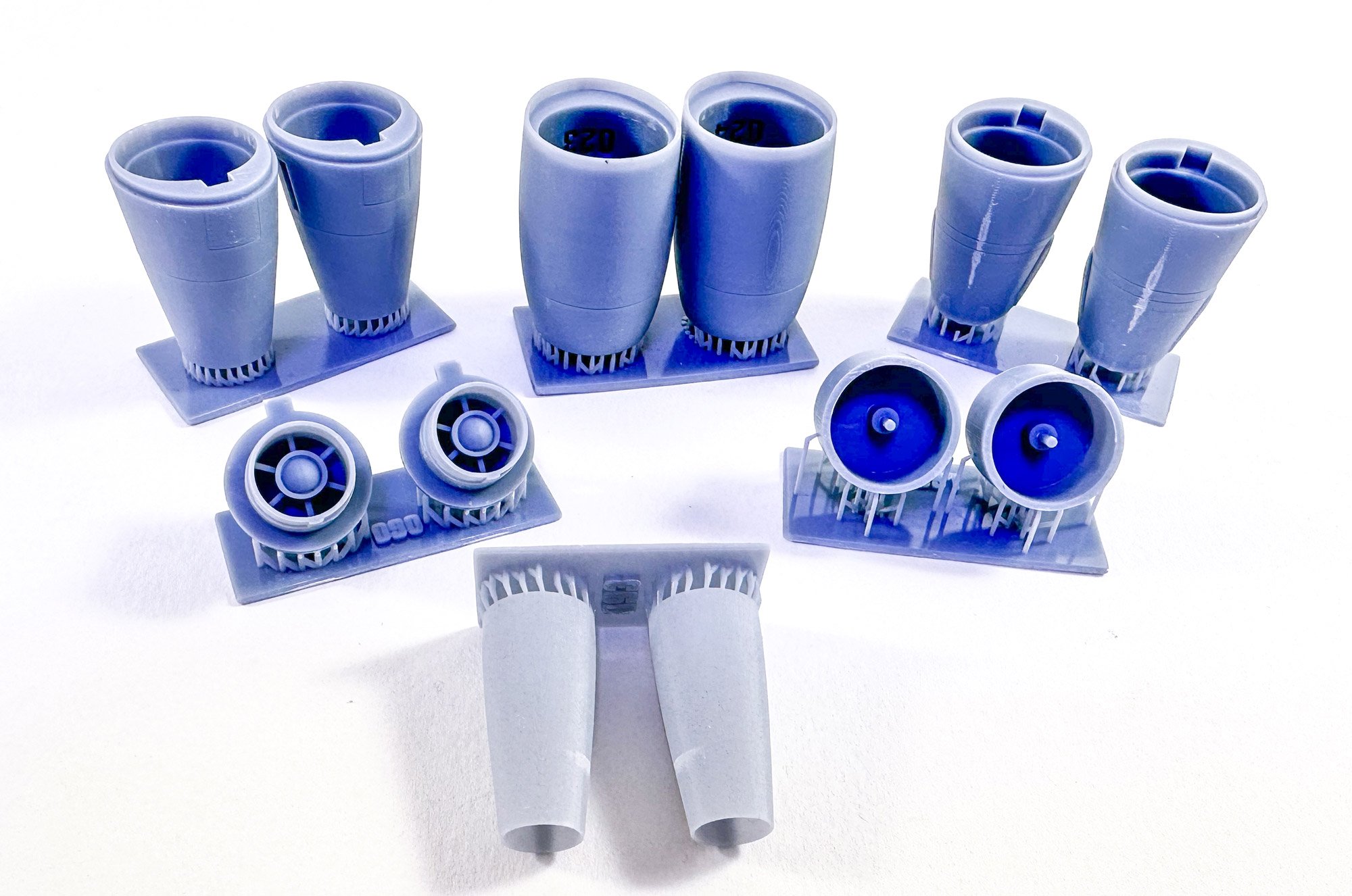
I'm still in the midst of rigging my HMS Indefatigable, so these pics are done with my iPhone and the 3D print leaves a sort of blue caste with the camera sensor. I think in future, I'll revert to DSLR.
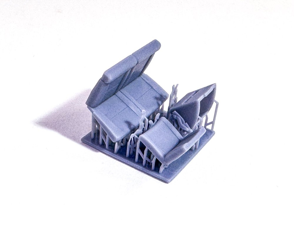
The kit itself is thoughtfully made and packed. It just took a clumsy postal system to cause one of the parts trays and guards to break, scattering parts into the carton. I've done my best to fix this for the photos, and leave the loose parts in front of the tray. When that lid is lifted, all parts and trays are sat in a strong foam frame.

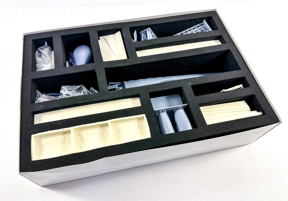
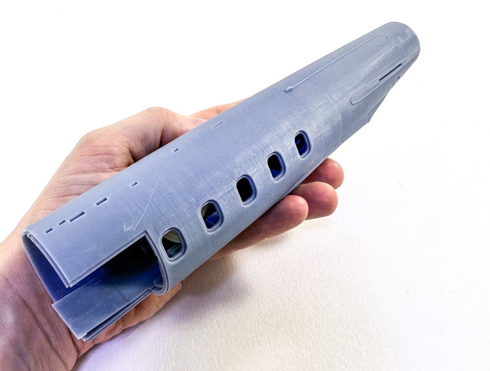
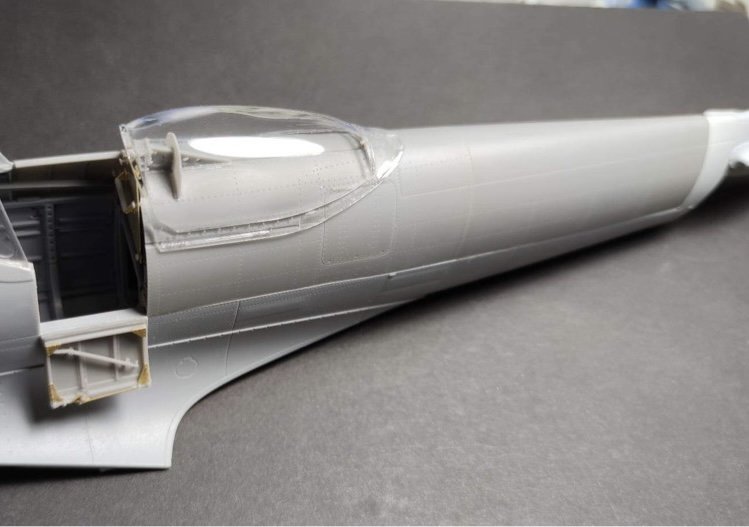
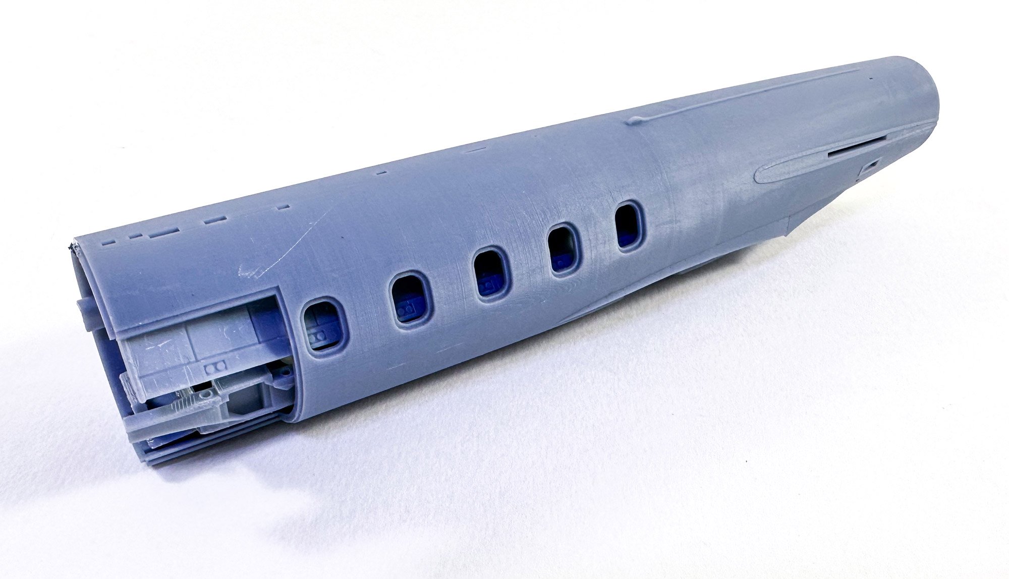
The fuse for this kit is built from three main sections, with the forward two in 3D print. The whole kit is a 3D-print/resin combo. I feel the kit was perhaps printed in 4K and something like this should've been in 8K to almost eliminate the print lines. It'll take some working to ready this for gloss paint, but it can be done. Here you see the fuse mid section, packed with other parts, as was shipped. You can see some surface 'scratches', but these are more just marks and will easily be removed when the fuse surface is prepped for paint.

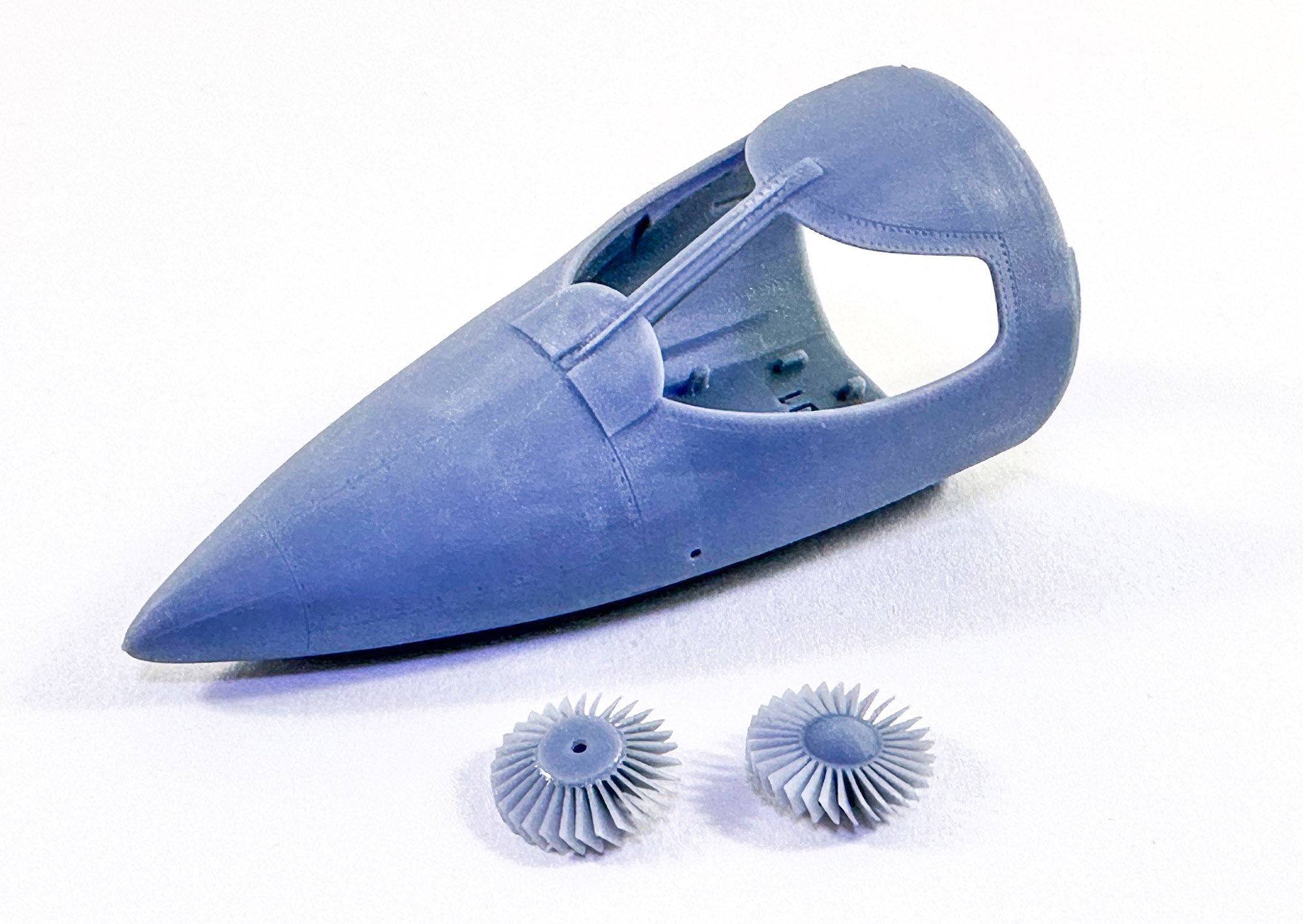
Just as an aside here, look at those impeller blades. They are just fabulous. This shows what 3D can do.

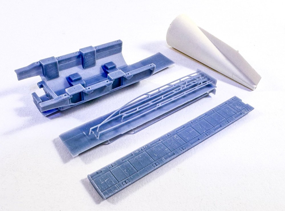
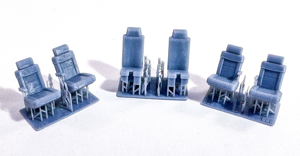
Here you see the parts that were stuffed into the fuse. These comprise the main fuselage internal cabin areas, and the rear fuse, cast in resin (for reasons not known). The seats are printed with separate seatbelts too.
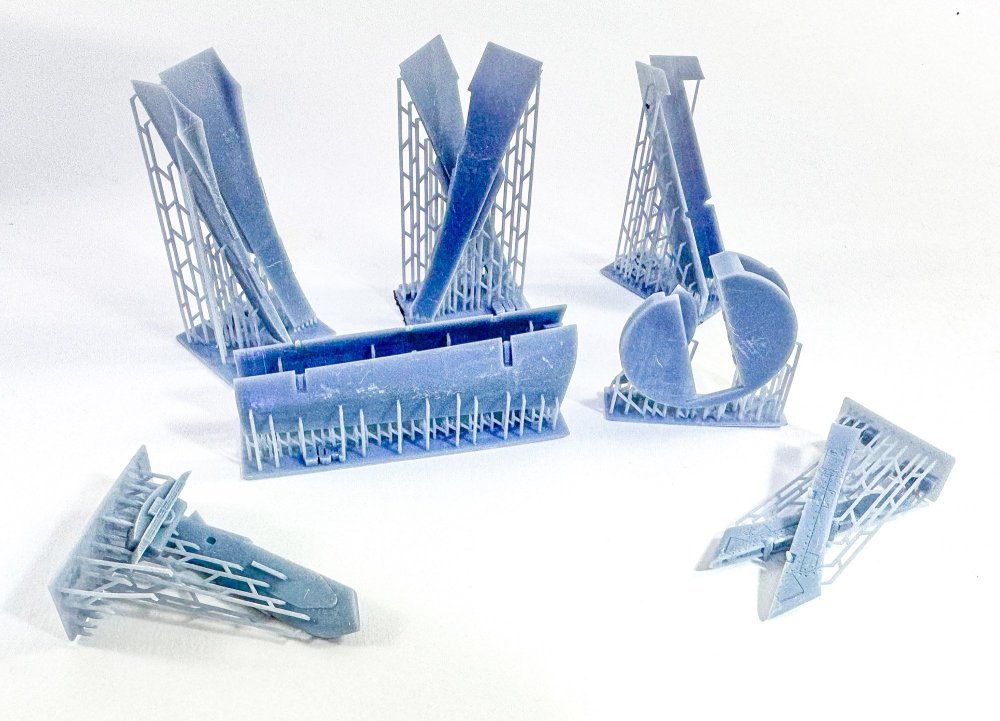
More 3D printing is included for the various flying surfaces. Despite my photos, the surfaces are very nice, subject to a smoothing, and the surface mars are just where the parts have rubbed against each other.
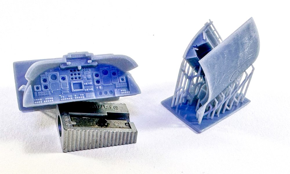
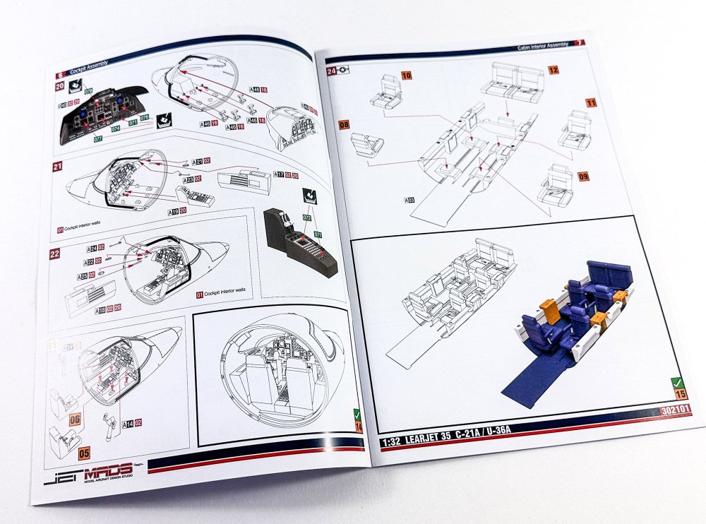
The instrument panel and coaming are integral, and decals are provided for the instruments. This is also very nice and will look great in paint. (remember, this stuff will need priming before paint, and I rarely ever say that!)
Here we have the varisou parts for the engine nacelles. The parts in the foreground are quite thin and beautifully made. Not sure if some craftily placed lead will be needed up front for this, but I'm aware of the possible fragility of the 3D printed struts.
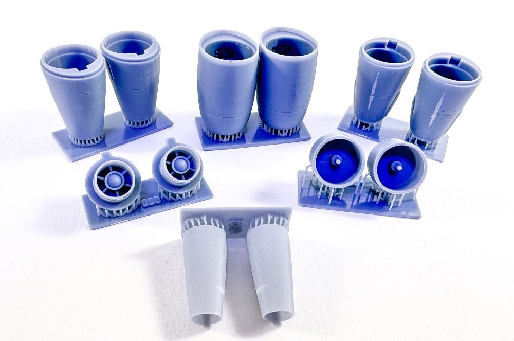
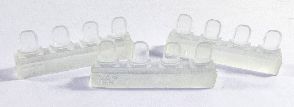
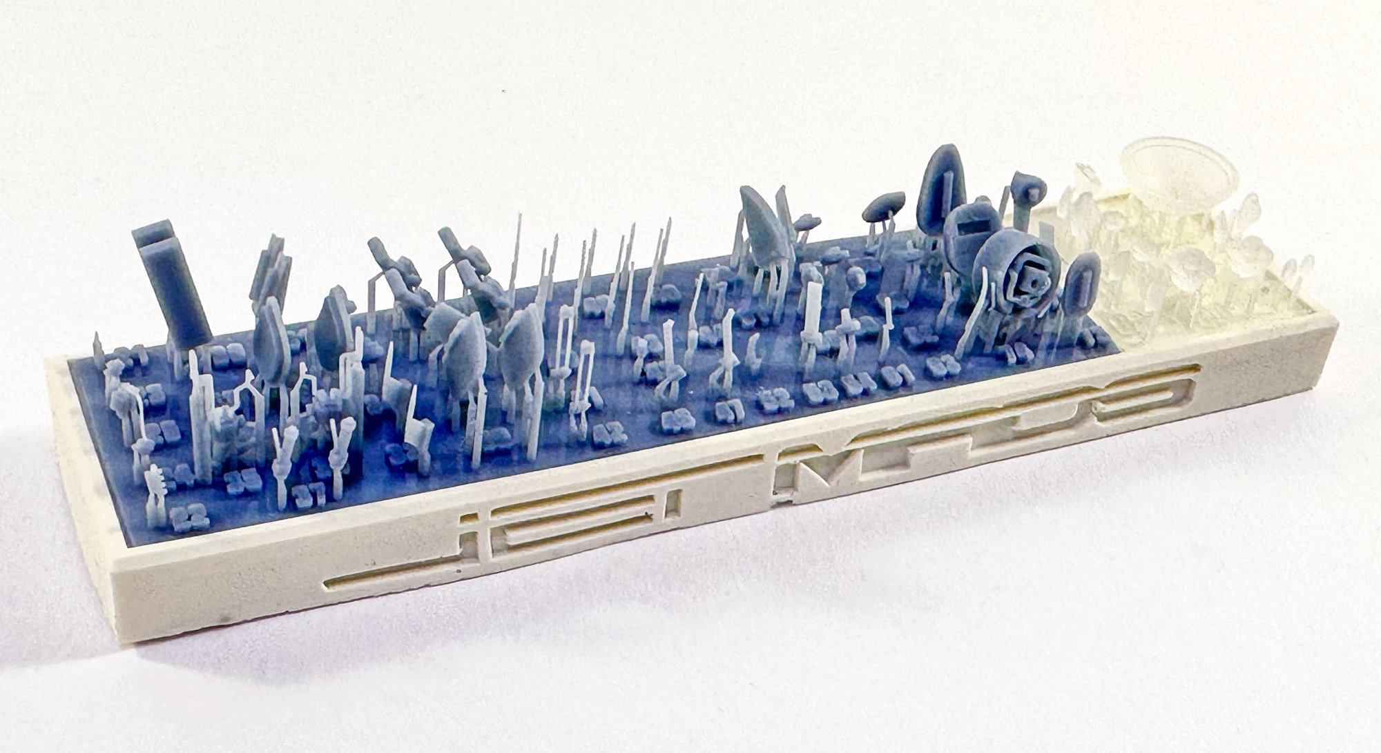
So where are the fiddly parts? Those are produced across two trays of parts, seen here. There are also some frosted clear parts which may need a polish before use. As with nigh on all parts, the numbers are included, and in this case, they are printed adjacent to each part. That's a nice touch.

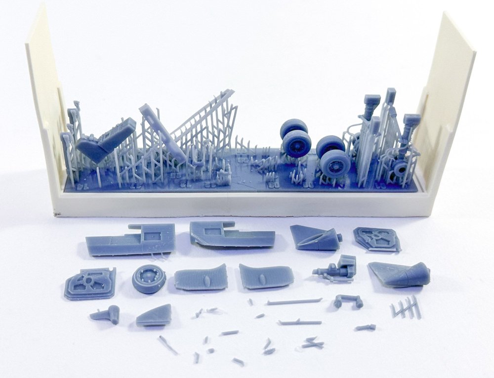
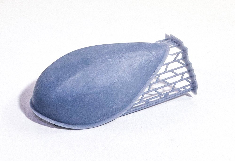
Lastly for the 3D parts, is this radome blister. This is for use with the Japanese scheme, of which I will definitely be building.
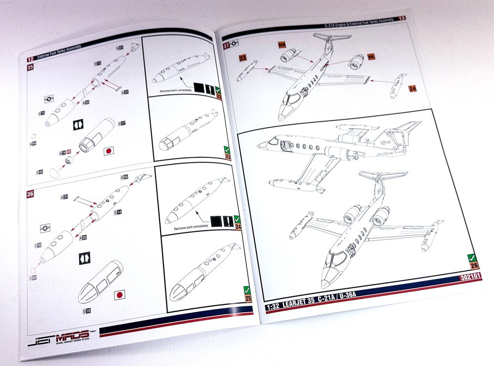
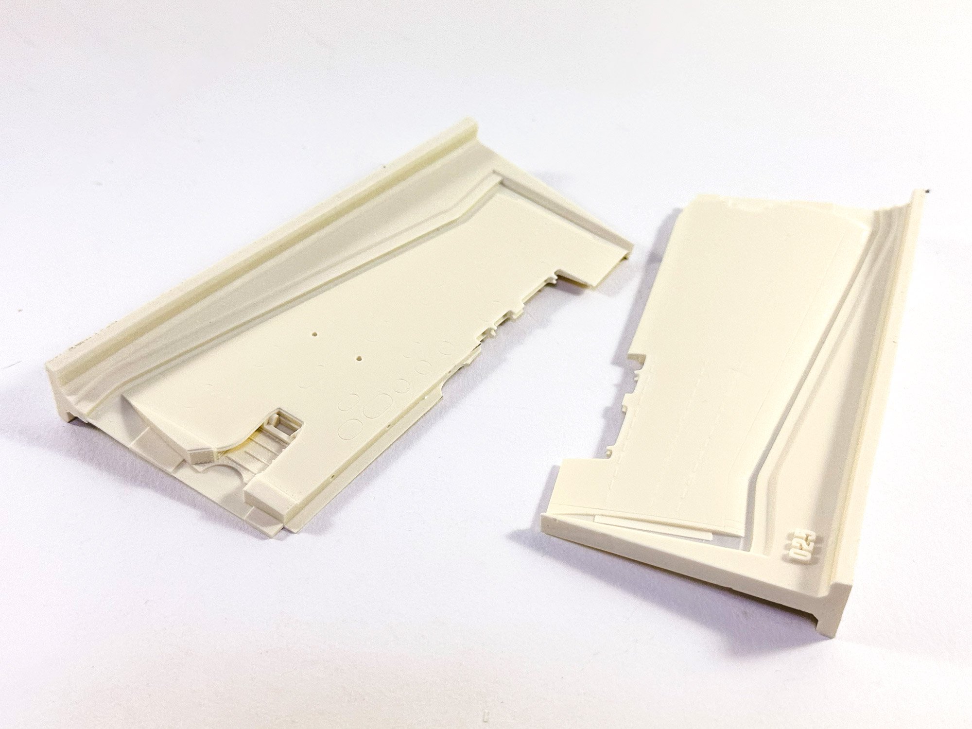
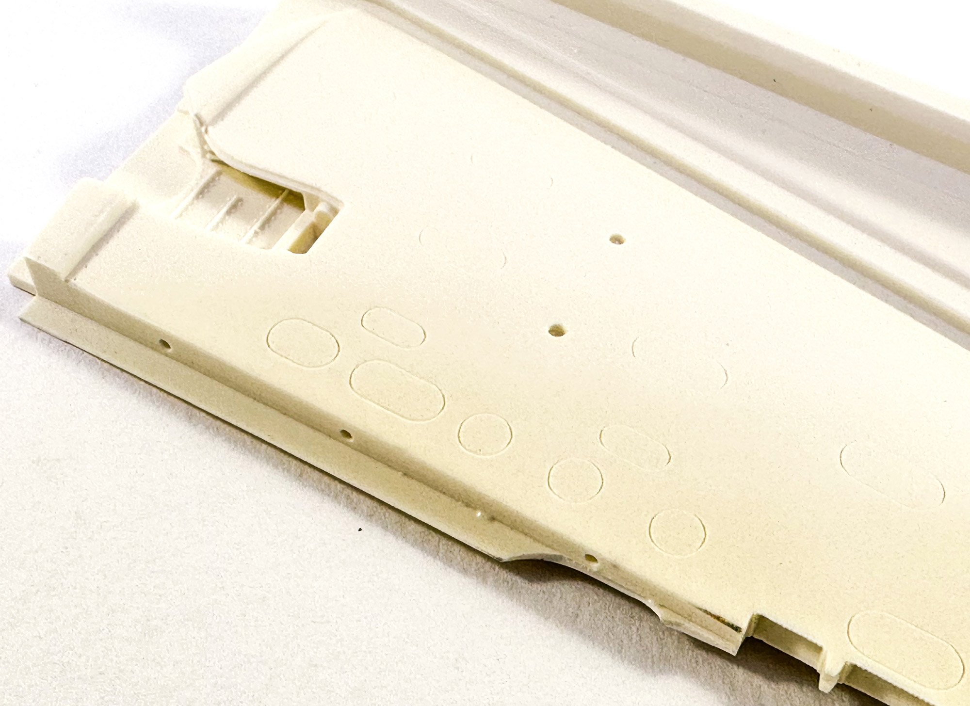
I did say resin was included, and this is used for the main flying surfaces (wings, tailplane, fin etc. This is cast in a cream coloured, soapy looking resin which does hold the detail nicely. There isn't too much surface detail needed on a lear, but the various access ports are nicely cast.

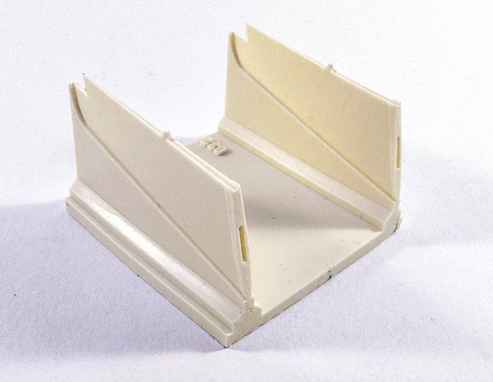
I didn't bother to de-bag these as I doubt I could get them all to fit back, but these are the various tip tanks for the wings.

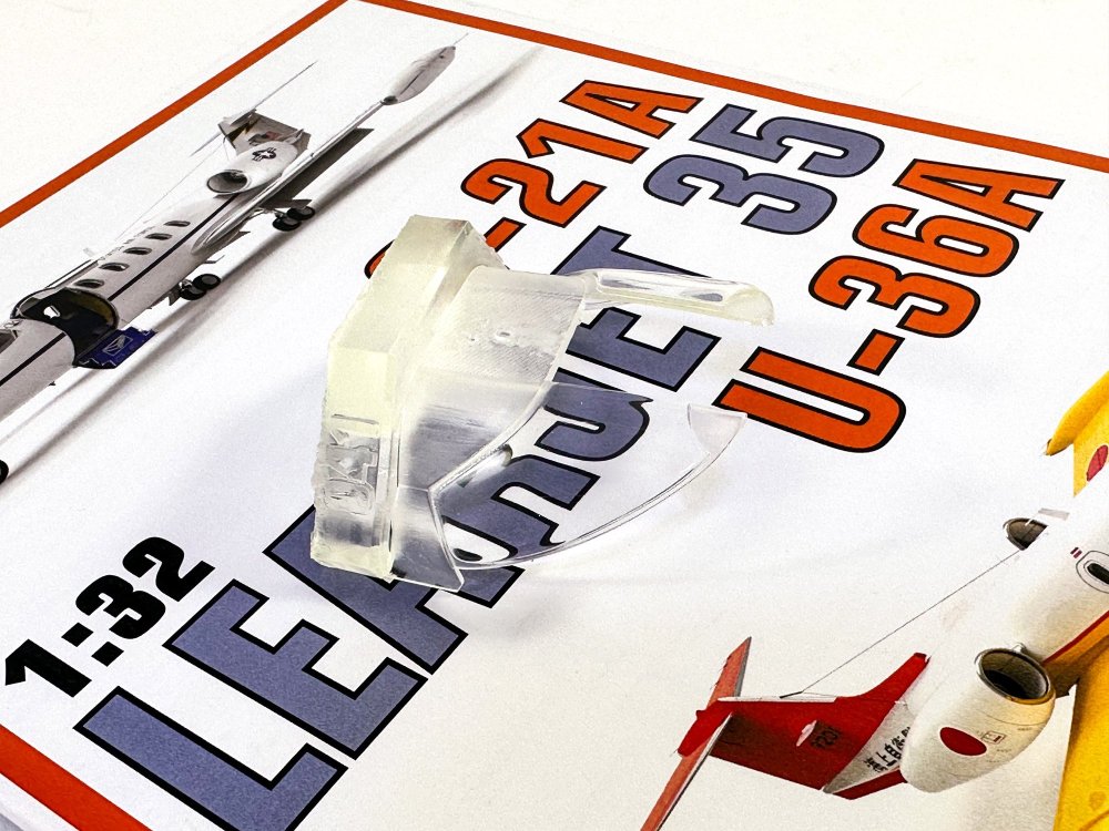
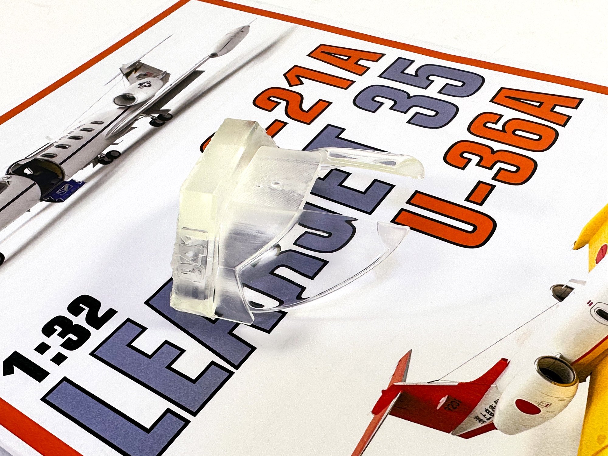
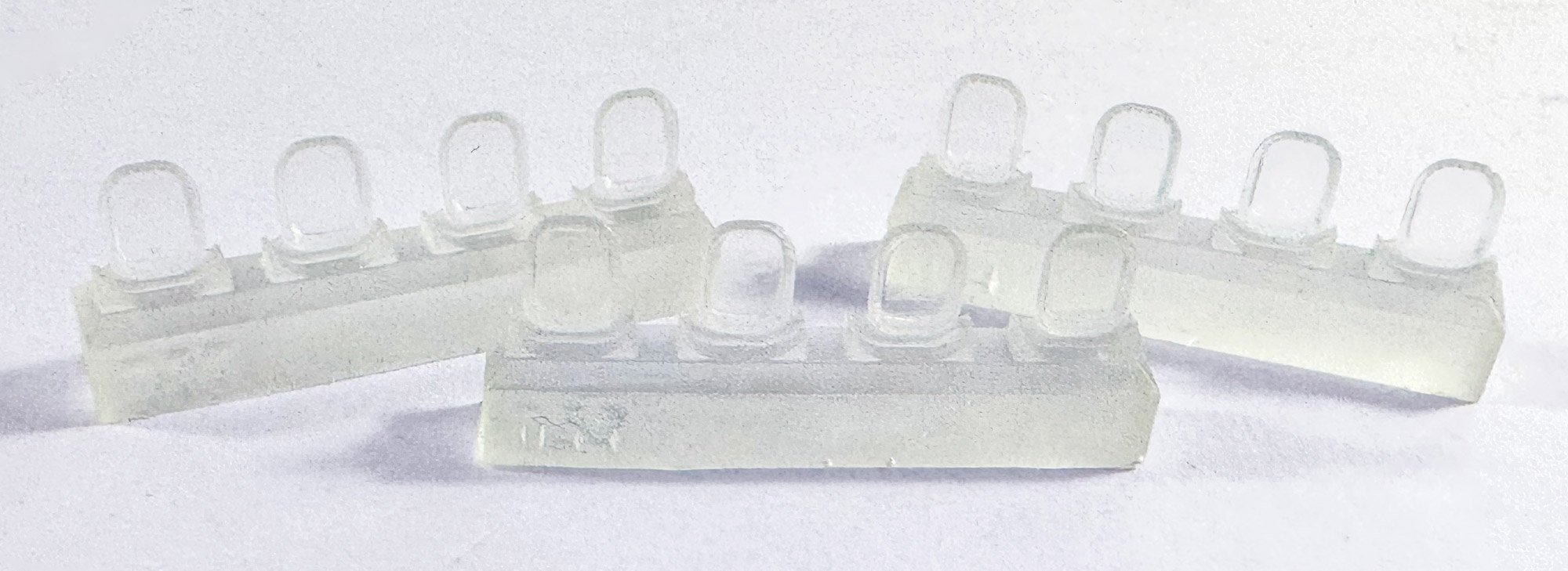
Clear resin is included for the main cockpit and fuselage windows. These are crystal clear and can be used straight from the blocks. I wish JetMads had included some masks for these parts, especially the fuse windows, so that the modeller can make them all identical.
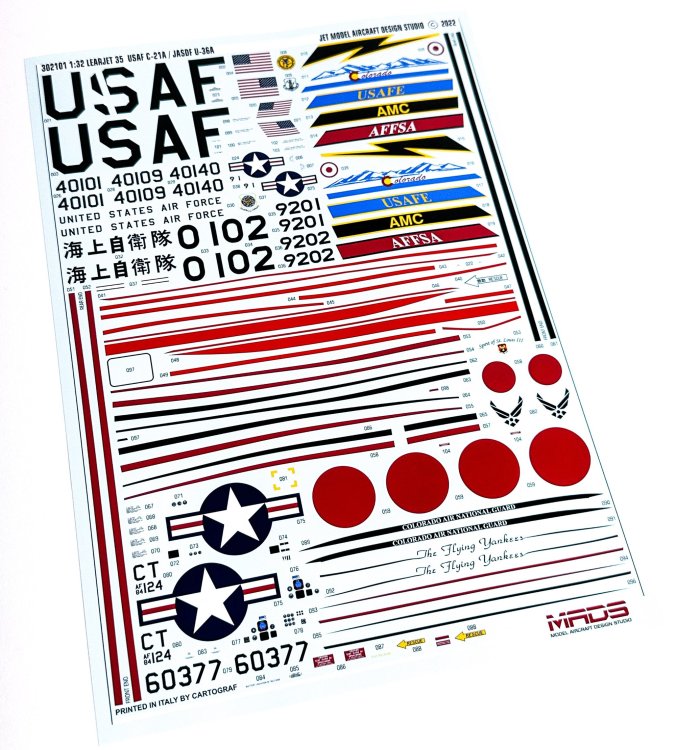
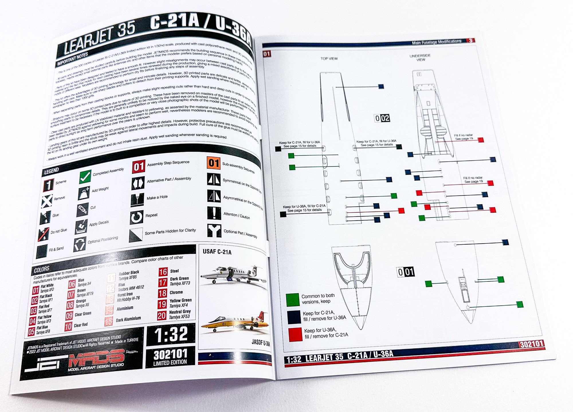
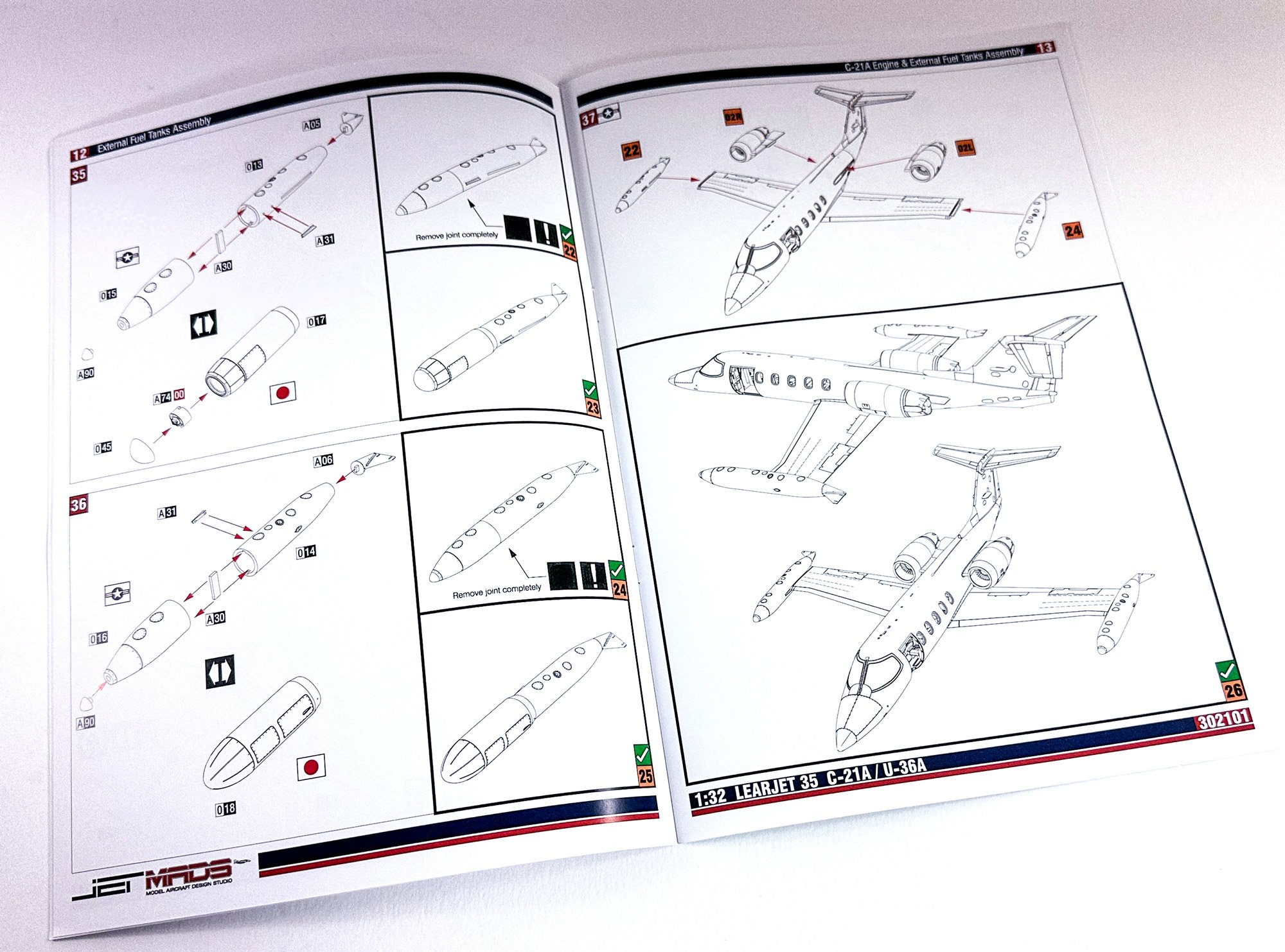
Instructions and decals
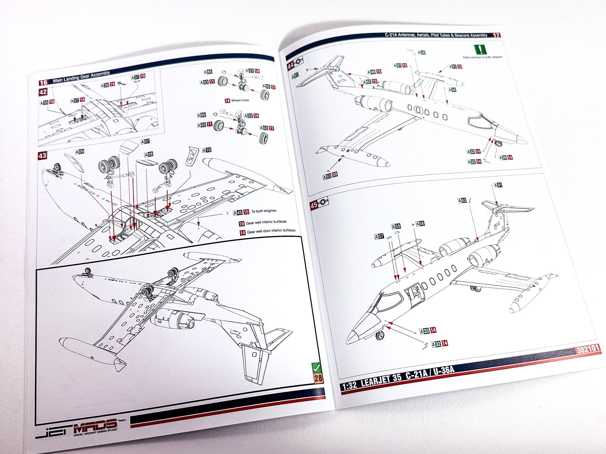
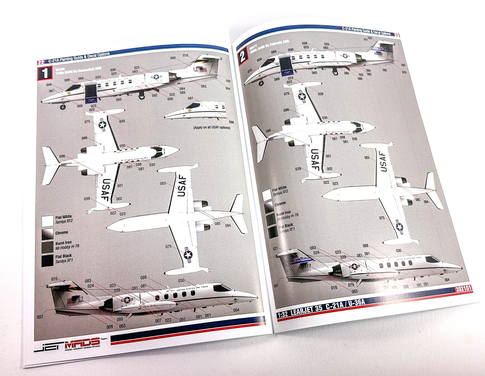
The manual for this is A4 in size and comprises a series of very detailed and well illustrated drawings which comprise colour annotation throughout. There are five US 'schemes' and one Japanese, although I appear to have not done a photo

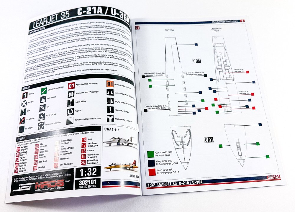

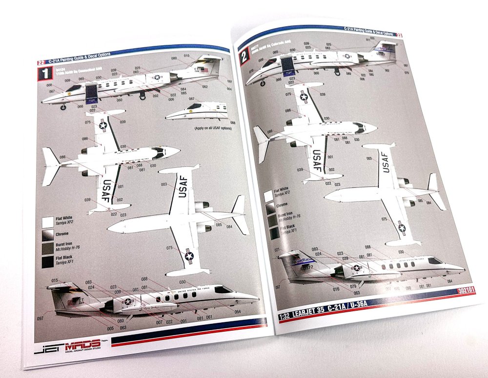
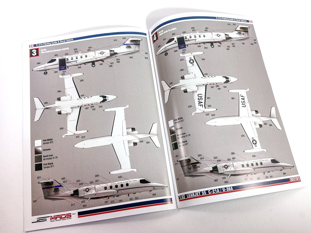
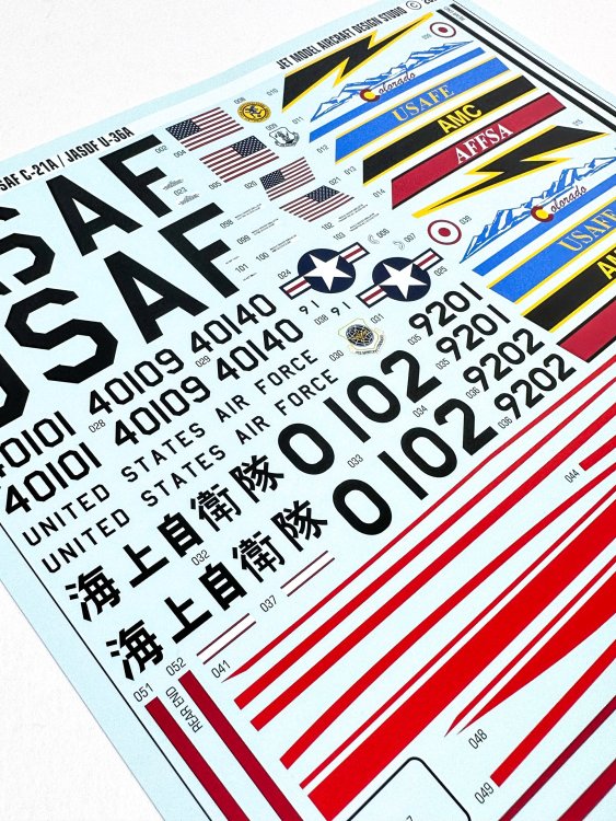
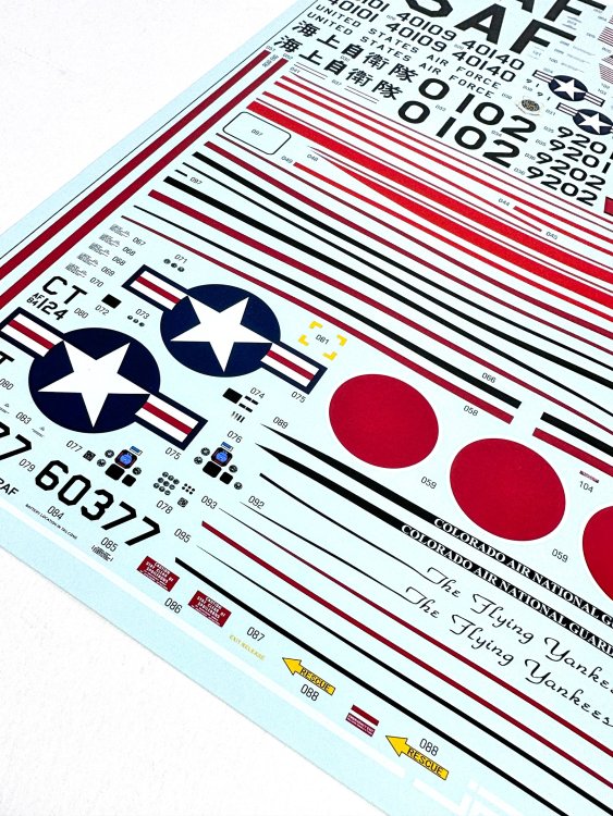
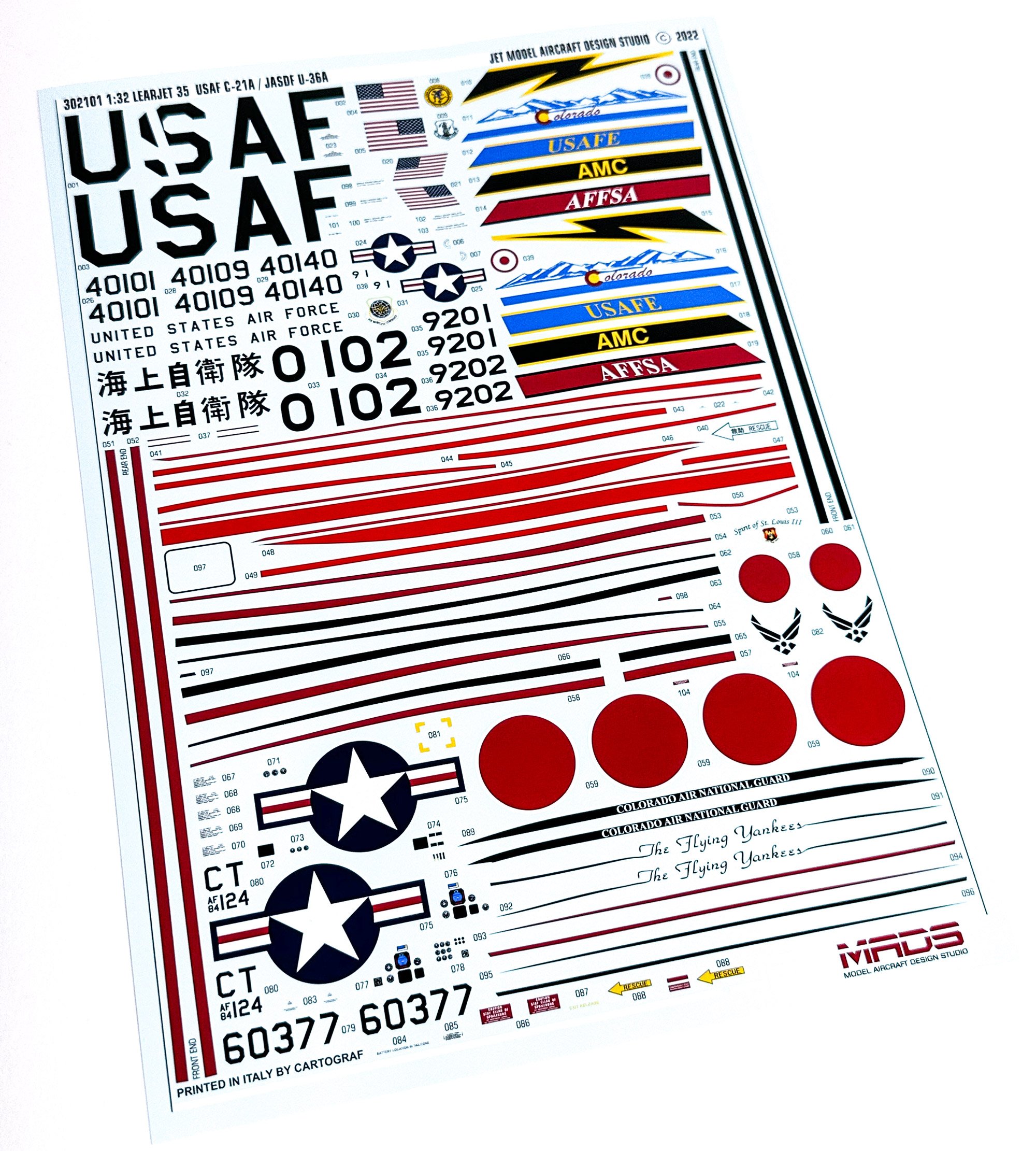
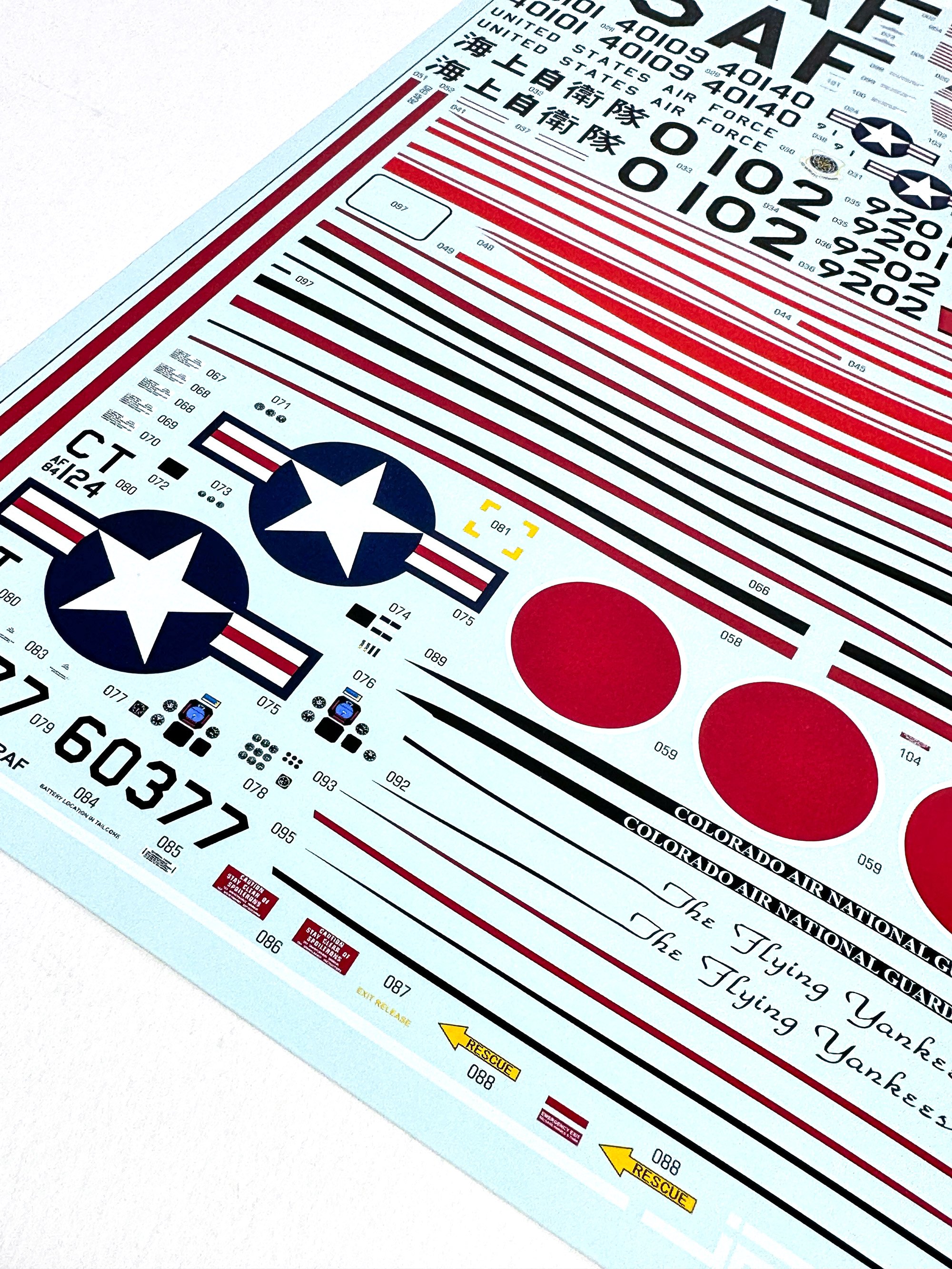
Decal are Cartograf and there's nothing to fault here in terms of print quality and registration etc. The various scheme option decals are clearly seen. Stencils are also included.
It's unfair to write a conclusion here as I have already said, I agree with Ernie's assessment. There is a lot of work to make this kit into the Lear you expect, mostly due to needing to remove all vestiges of the 3D print lines, but hey, this is supposed to be a hobby! My only real criticism is that they should've included those canopy masks too, and perhaps something sturdier for the beautifully detailed undercarriage struts.
A I write, this kit I out of stock, so don't really know if this is moot, but it will give an indicator of what to expect from a JetMads kit.
My sincere thanks to Ernie for this opportunity in looking at this kit and also to getting it built up later this year!
-
2
-
1
-
-
I've done as was instructed to get the Gallery online but there's a couple of issues flagged on install.
I've ticketed Invision, so hopefully this will happen sooner rather than later.
-
3
-
3
-
-
Have you tried deleting your browser cache and cookies?
If you've some corruption stored there, that could affect it. Try another browser to test.
I run a site with 42k members which operates the same software and there are no reported issues.
-
1
-
1
-
-
18 hours ago, belugawhaleman said:
Nope. Tried it, doesn't work......a parroted comment? Don't know.
I've been doing the same way for at least a couple of years....then, suddenly,
the way I've been doing it doesn't work.....Anyway, I found another way.
I know the "change" occurred after the site was down. Thanks anyway.
Regards;
Paul.
The reason the site was down was due to a power supply outage to the datacenter where we are hosted.
There were no actual software changes made to the site.
-
I do like that ZM 190.
I just figured that my wife would kill me if I bought another kit.
-
5
-
 1
1
-
-
1 hour ago, biggtim said:
Let me know via PM if you do. Another person asked for that one, so I've already been working on getting the parts all hunted down and put together. Should be ready soon.
Cheers.
When I locate a kit, I defo want that set.
-
4
-
-
I'd love an F-86 set.
Problem is I need the damn 1:32 Kinetic kit too. Not easy to find.
-
4
-
-
Ok, there's been no change to our system here that would cause such an error.
If you paste something into the sig area, the editor will probably carry over any original formatting.
A tip to get around that is to paste text into your browser address bar and then copy it again and paste to your sig. That removes all formatting. You can then amend as you like.
-
1
-
-
Yes. Absolutely.
Not moulded in that shitty, soft and soapy plastic any more. The sprues don't even look like typical Airfix ones and the detail is outstanding. I believe they are now moulded in the UK and not that crappy place they were using in India.
-
3
-
-
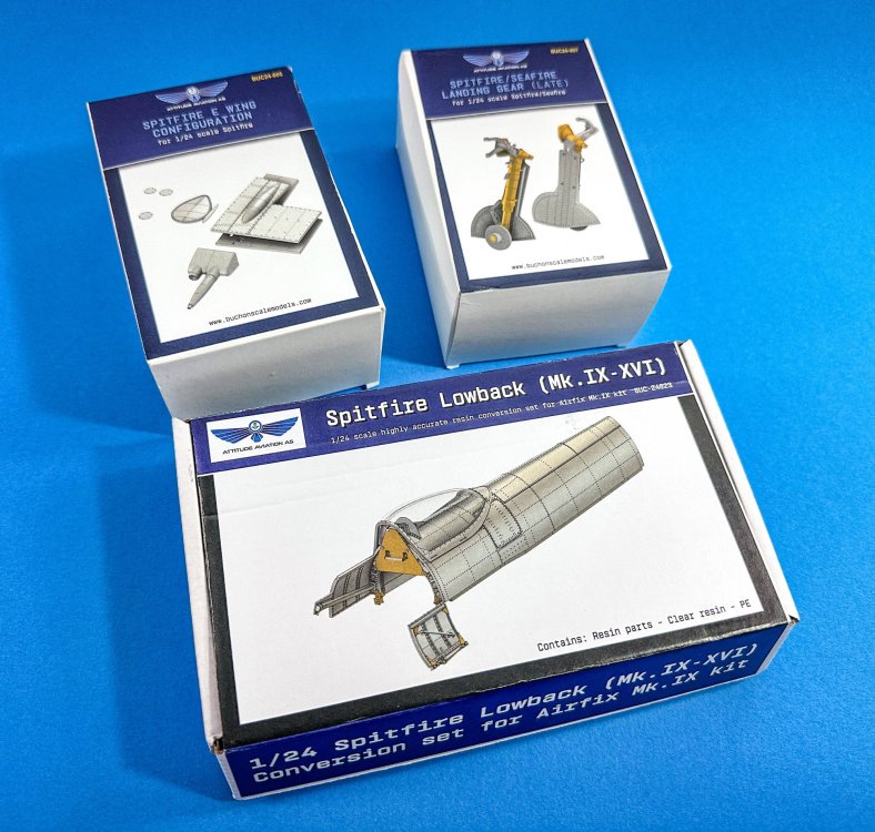
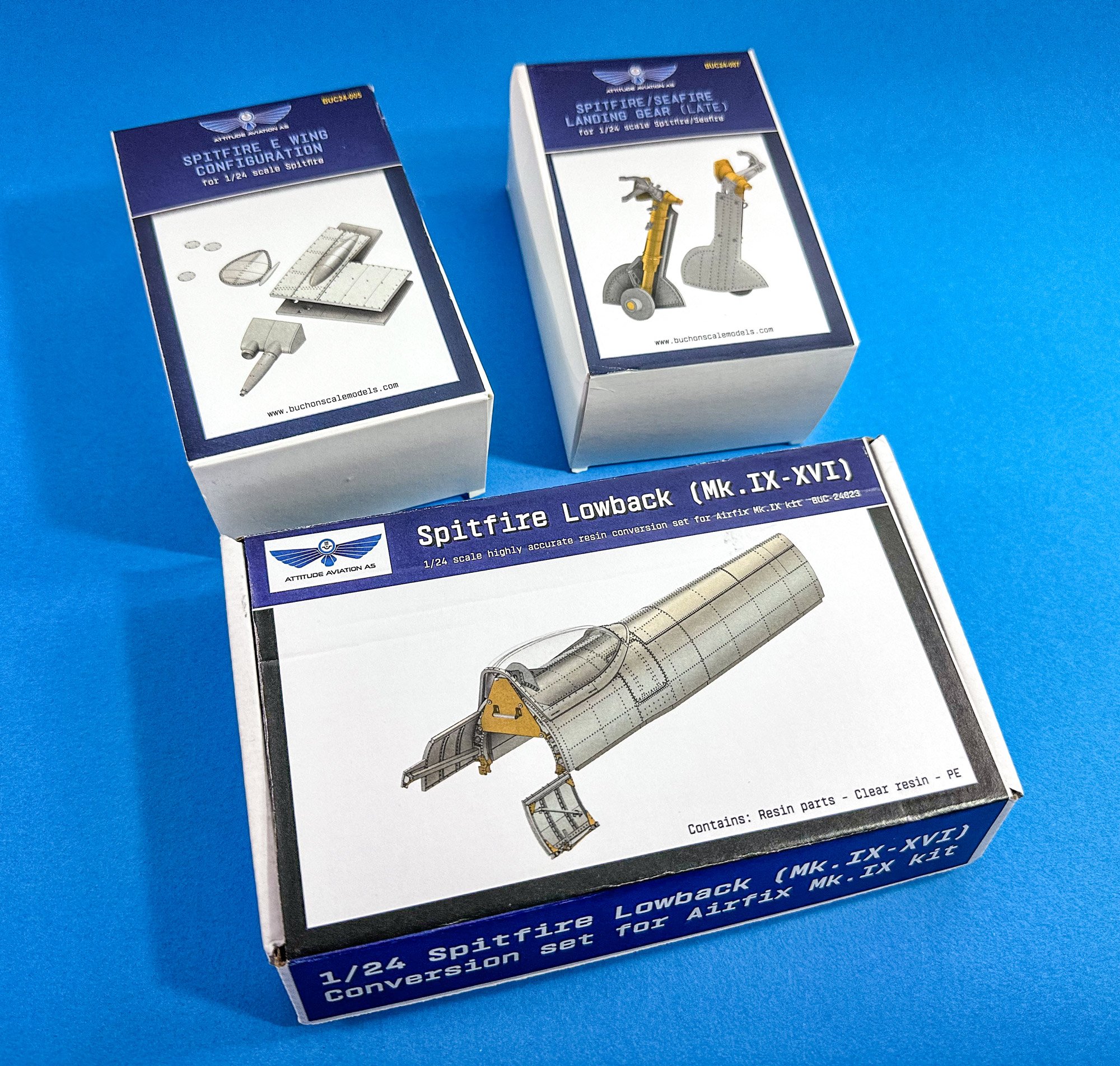
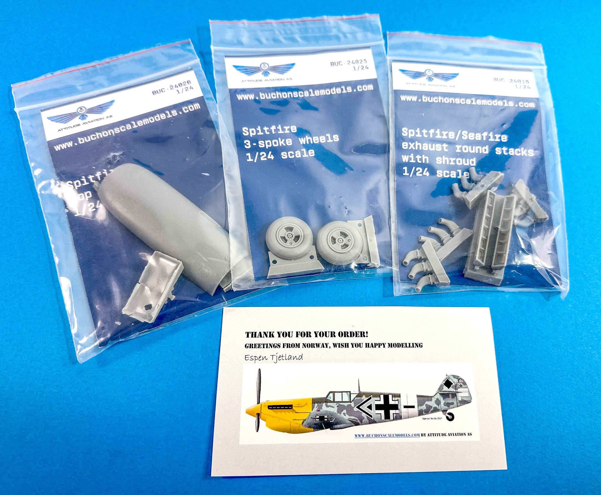
Ok folk,
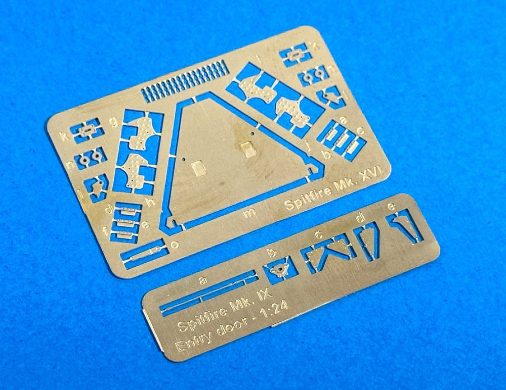
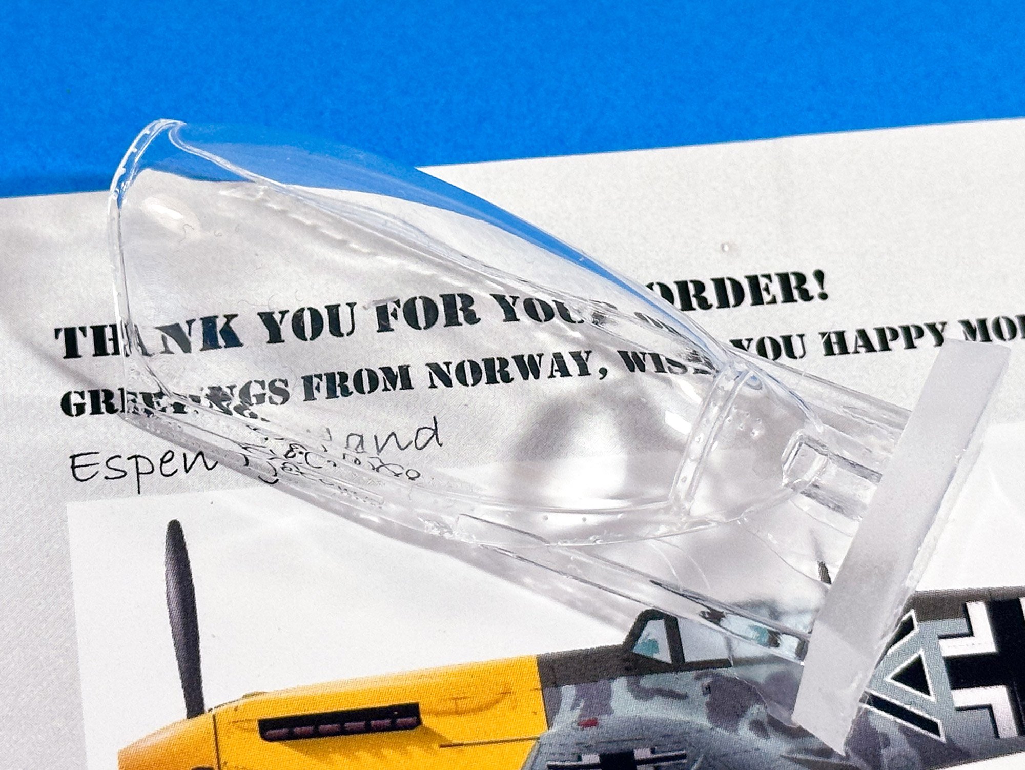
This isn't so much a review, but more a 'first look'. I managed to get some time last night to do a few photos of the items that Espen sent me for the forthcoming 1:24 Spit Mk.XVI. All of these are cast in grey resin, with the exception being the crystal clear teardrop canopy of the low-back Spit. The low-back conversion also two small frets of PE. My apologies for doing these on an iPhone as I desperately need to upgrade my camera in the next months.
These sets cater to not just the Sweet Sixteen, but those who want to upgrade the base kit, such as the nicely produced brass undercarriage parts. When you load up a model with resin, those are definitely something that you ideally want to have to protect your finished work.

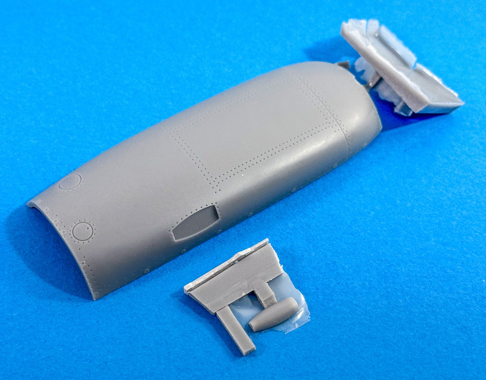
Cowl top
Now, not having looked clearly at the Airfix kit yet, I'm not too sure how this differs from the kit part. I have to assume it's in shape, somehow. A small casting block at the front is all that needs to be removed. Mine was snapped off in transit, and I've a tiny break to fix, but a couple of mins work will sort that out.
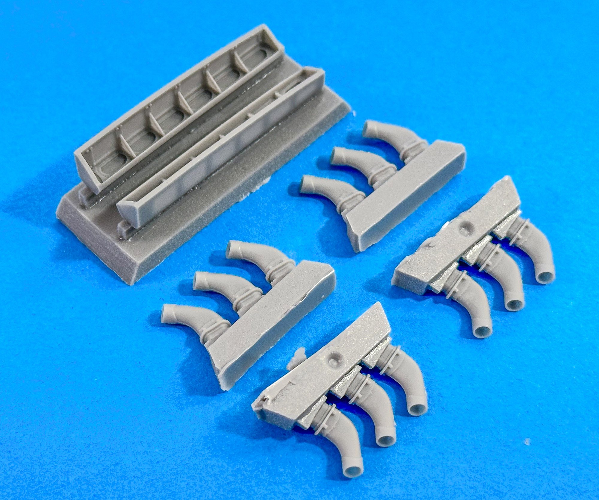
Spitfire/Seafire Rounded Exhausts
The Mk.XVI will absolutely need to be fitted with this set. I'm sort of thinking that this can be used with the engine, but the parts will need to be grafted into the thin side frames that sit outside the engine sides. If not, I'm sure I can be selective on at least showing one side of the engine exposed. The stub casting blocks have indents to ID them for the correct side of the engine.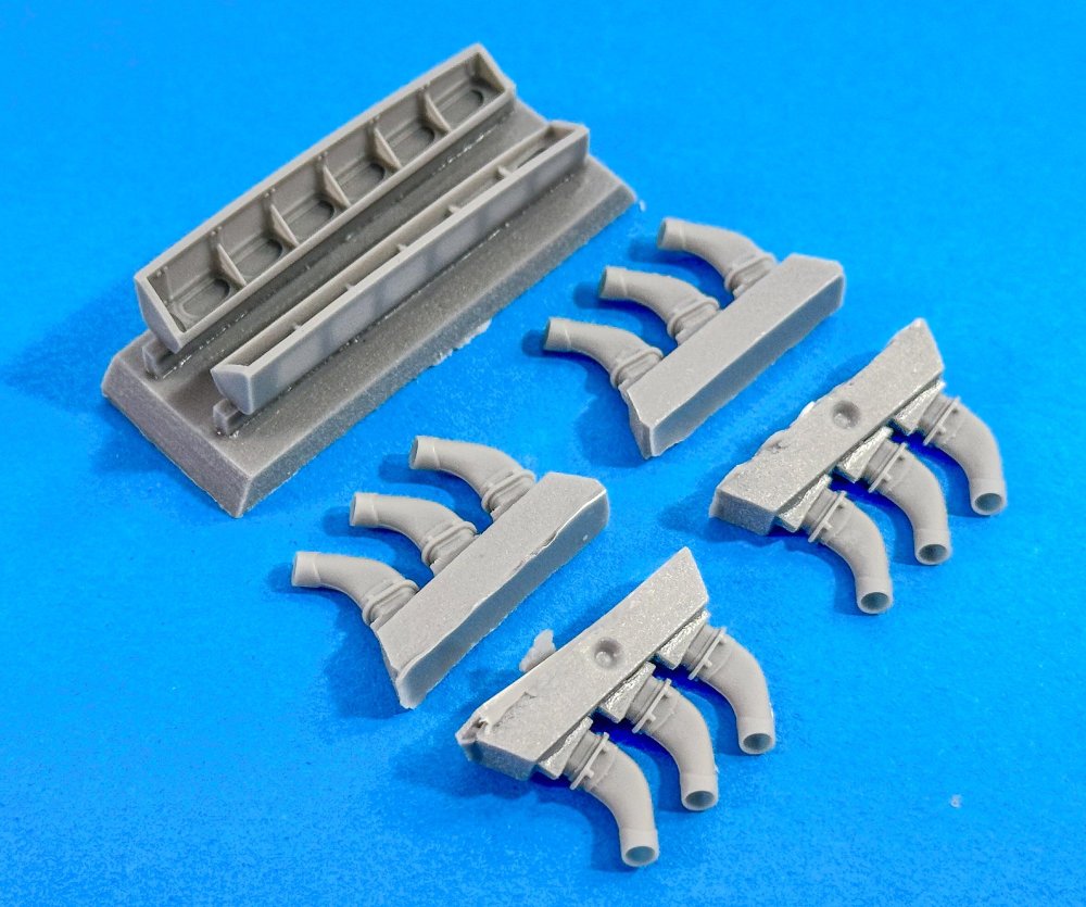
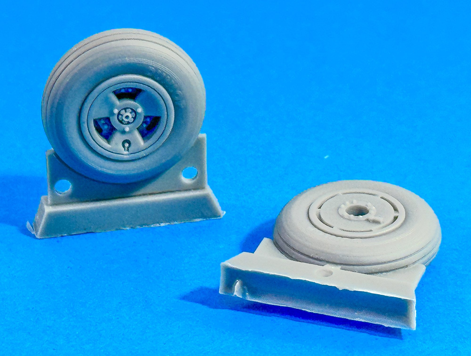
Three Spoke Wheels
A simple, direct replacement for the kit part. The casting seam runs along one of the smooth tread lines and will be very easy to clean up.
E-Wing Configuration
I'm told this will be a very useful set to fit to the Mk.XVI. This set was designed for the old Airfix kit, but not all parts are to be used on the XVI. Those that are, I am sure can be made to work.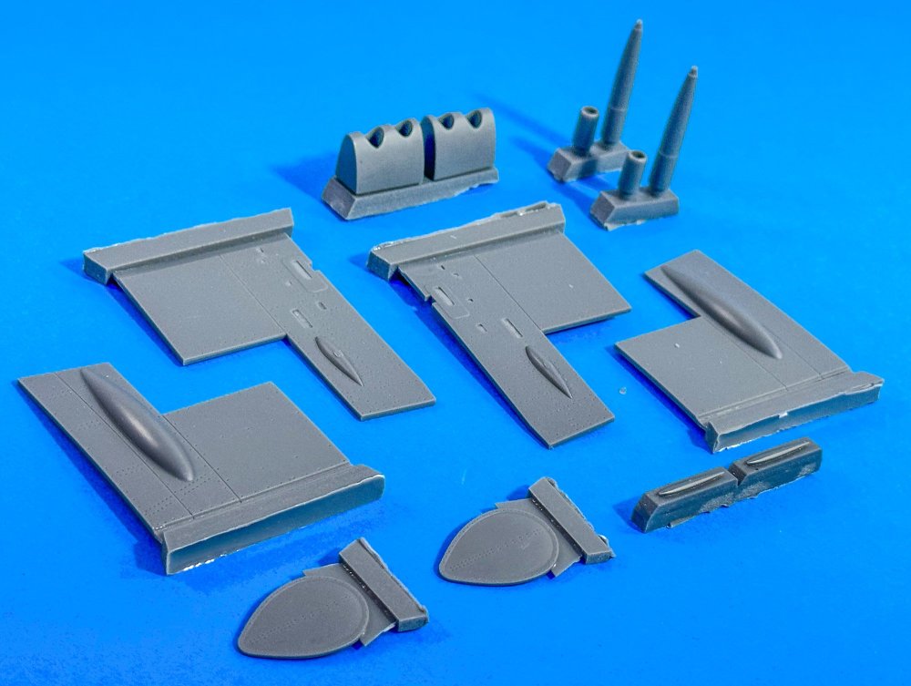
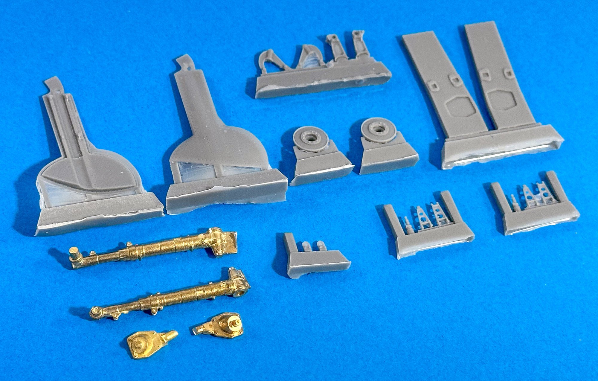
Spitfire/Seafire Landing Gear (Late)
This is a straightforward set to fit to the new Airfix kit, with the brass legs just requiring very minimal cleanup. The overall detail is really very nice., including those gear doors with their thin edges.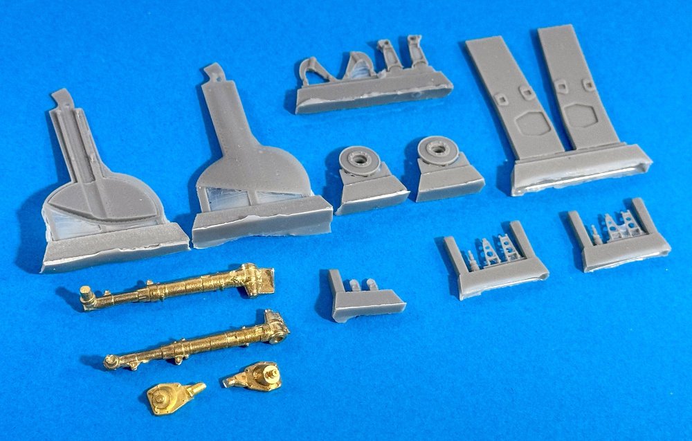
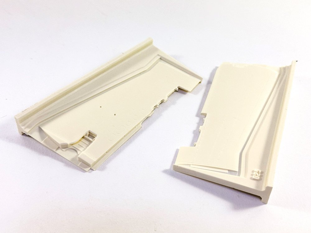
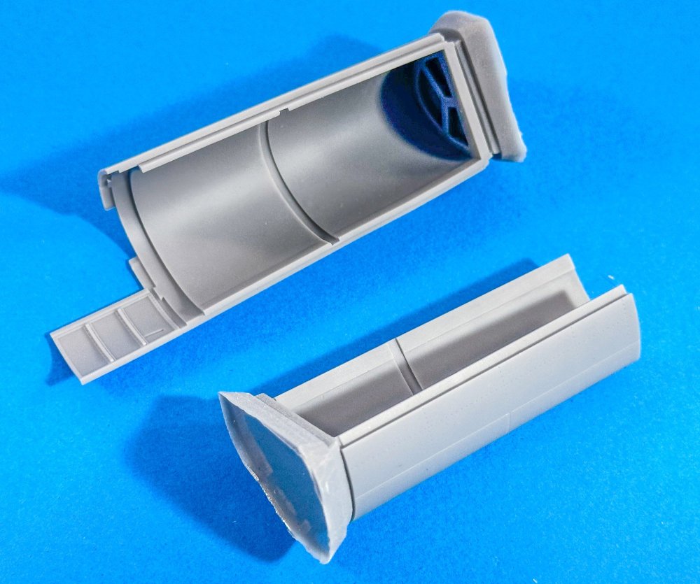
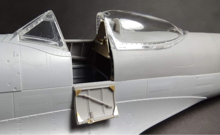
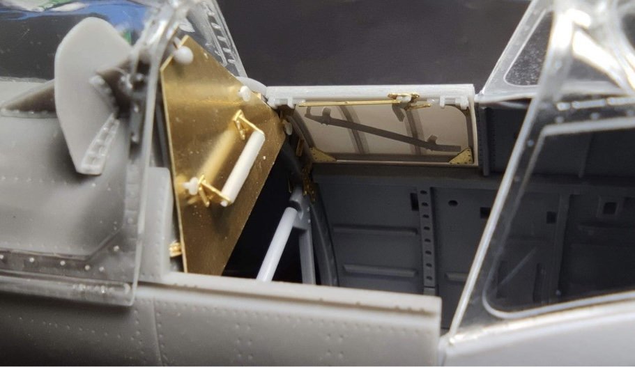
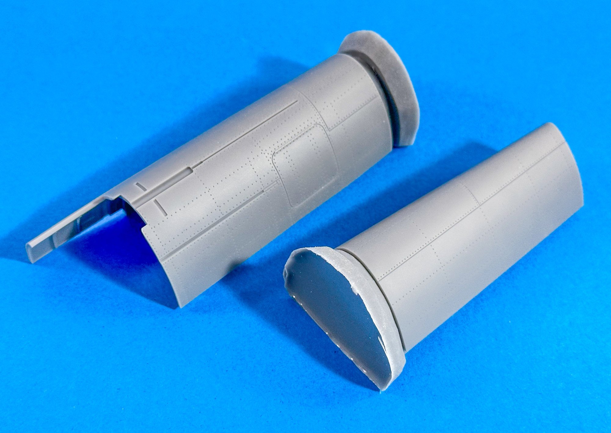
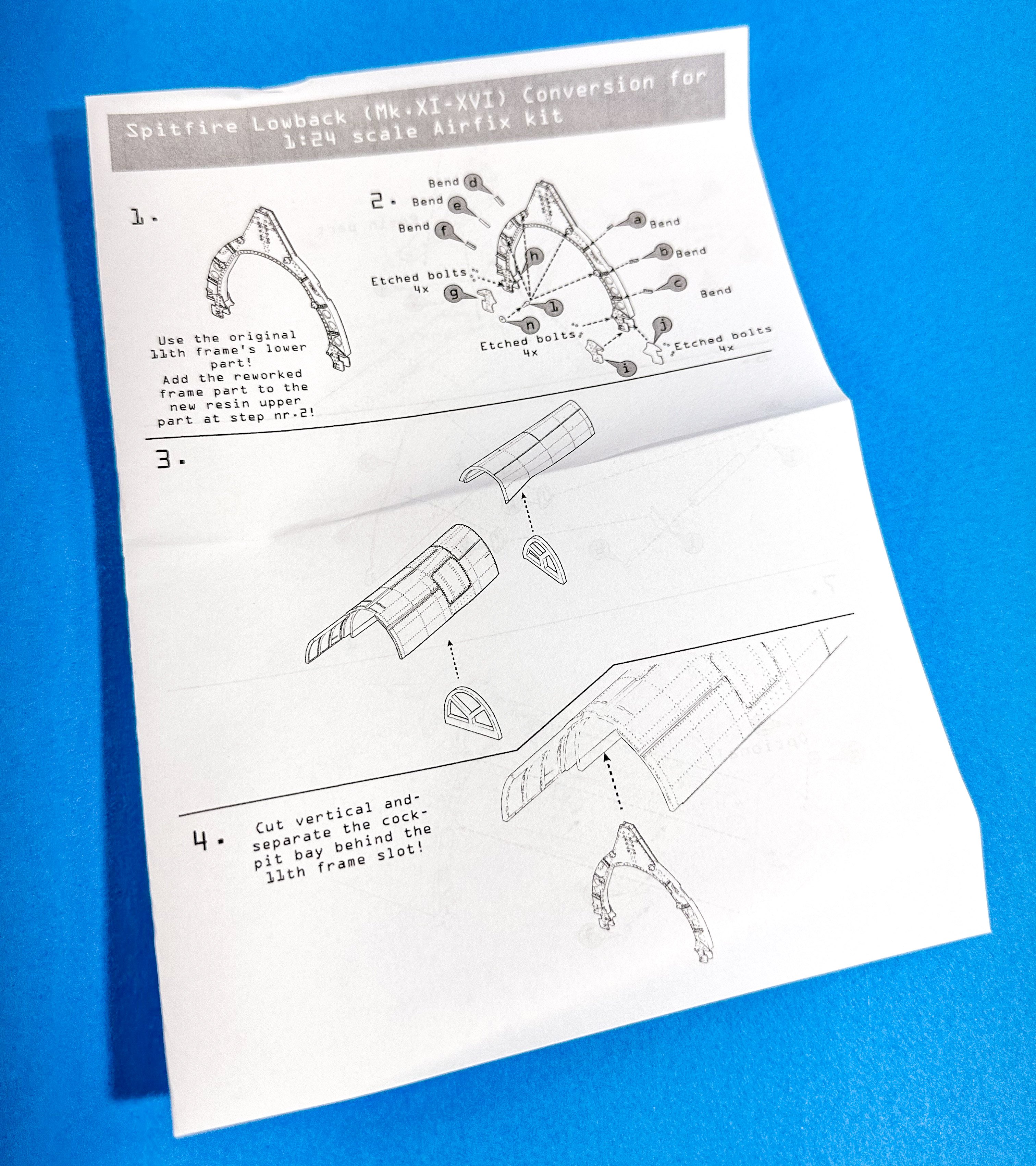
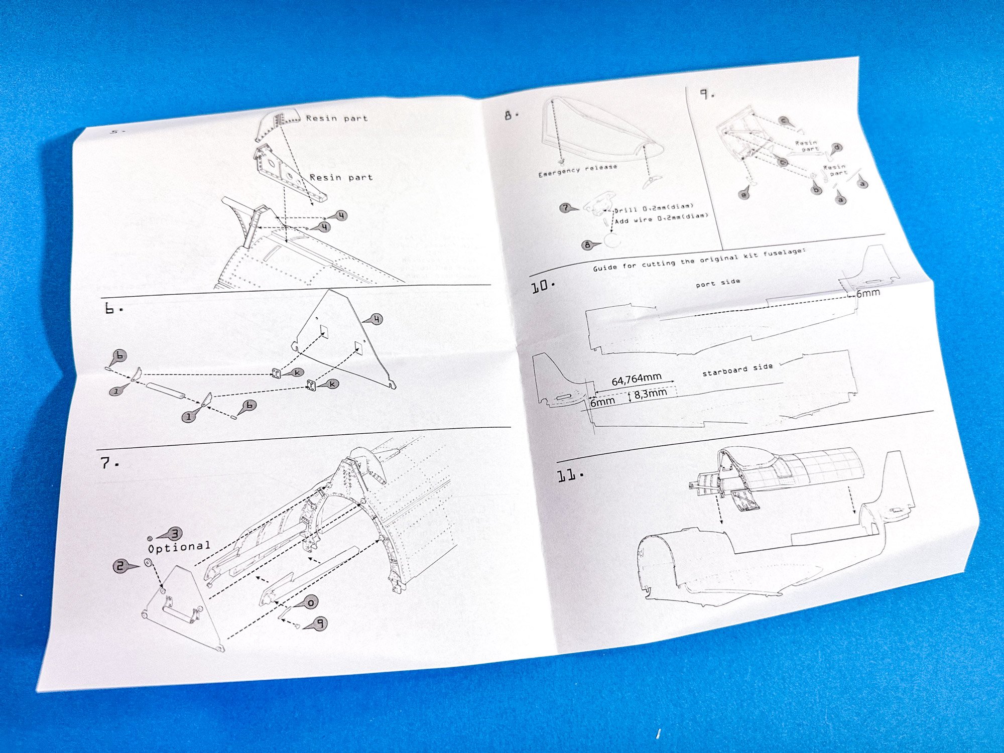
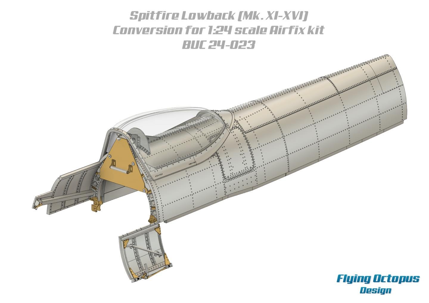
Spitfire Mk.XVI 'Low-back' conversion'
If any set is going to give you palpitations when it comes to converting your new kit, it's this one. The fuselage will require some careful cutting down, aft of the cockpit, along specific panel lines. The new spine comes in two parts, with each having a cast former to glue within. I've not removed any blocks at this point to see seamless these parts sit together, but I'm not at all worried when I see the one that Espen has been showing. Plus, having built his Buchon conversion, I know he's a stickler for getting things right.
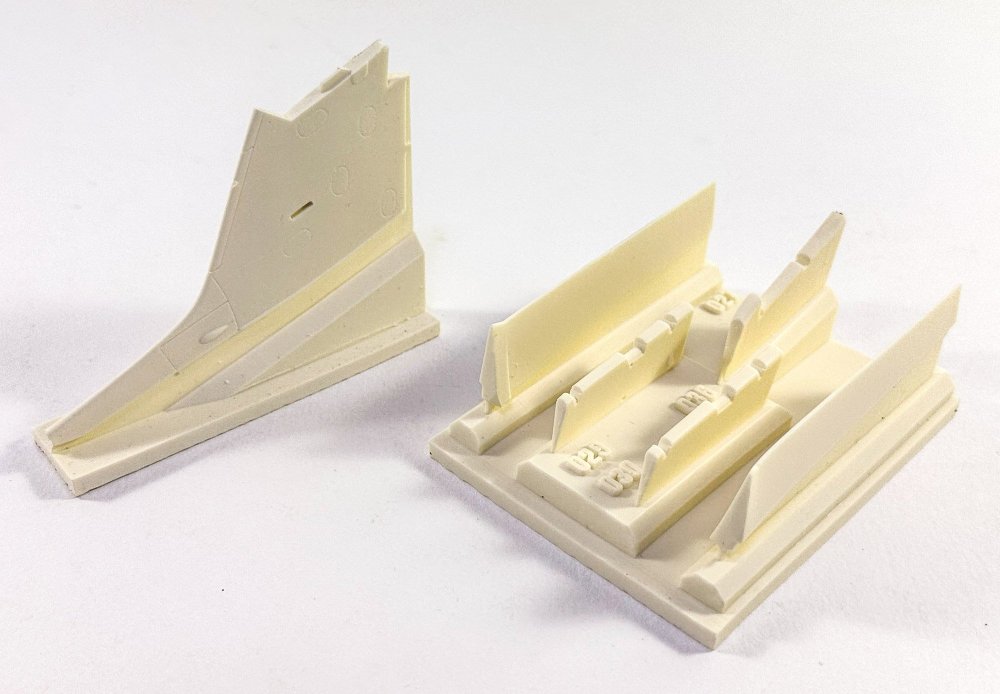
Here are the rest of the resin parts for the conversion. There is also some supplemental resin for adding fishplates to the fuselage former to the rear of the pilot, as well as the armour plate.
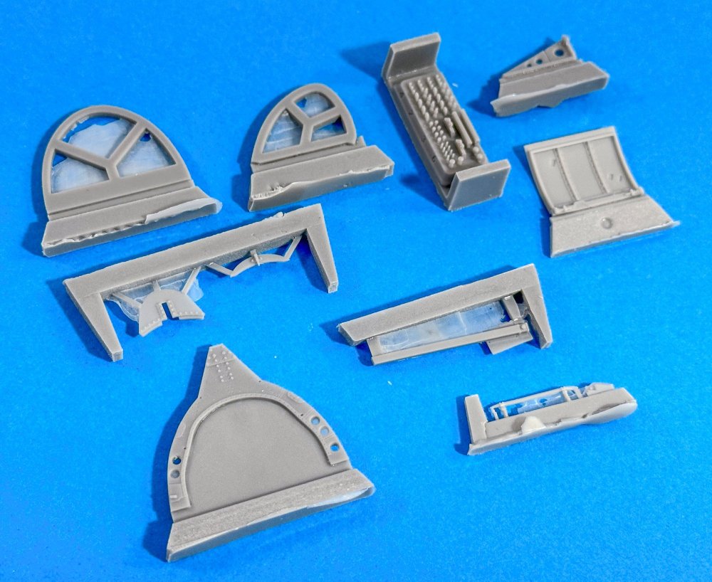
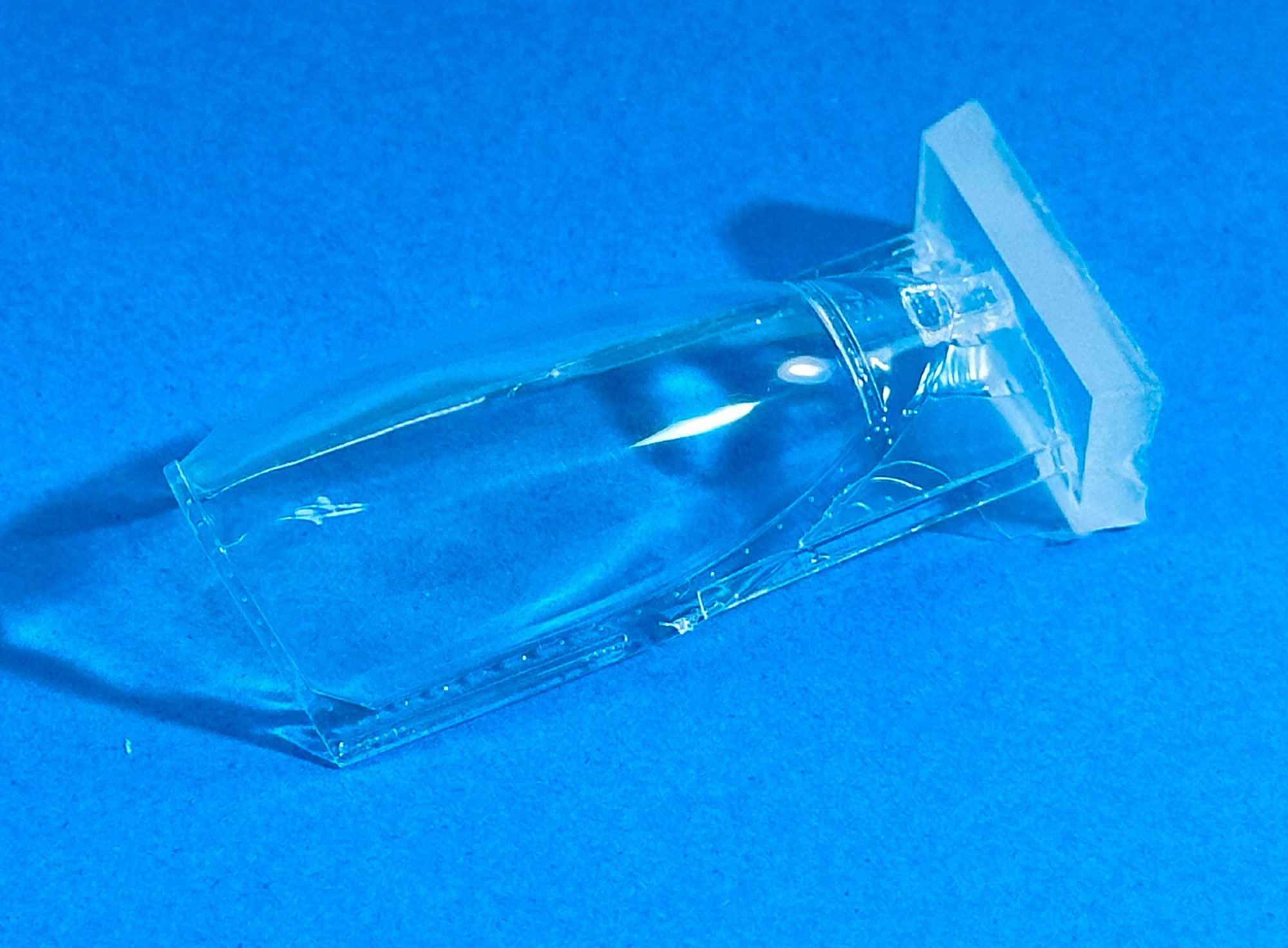
A real crux for making this is a successful conversion is getting the new teardrop canopy right. And here it is. Beautifully cast and totally crystal clear. The only distortion comes from the curves as you look at the part sat on some text.


As you can see, the instructions are very detailed about the hacking and slashing you will need to perform on the base kit.


Until I get to this project in July, that's all until then. These sets really are very nice, and my thanks goes to Espen Tjetland in sending these out for the forthcoming Mk.XVI build. I seriously CANNOT wait!

-
2
-
1
-
-
Calm down folks. Let it drop. Pointless gong round in circles and beating each other up.
As you were!
-
1
-
4
-
-
11 hours ago, PanzerWomble said:
people you think are throbbers ?
PMSL!!
Not hear that term for ages! I can tell you're UK 🤣
-
1
-
-
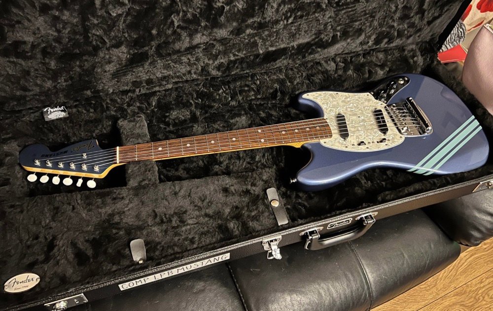
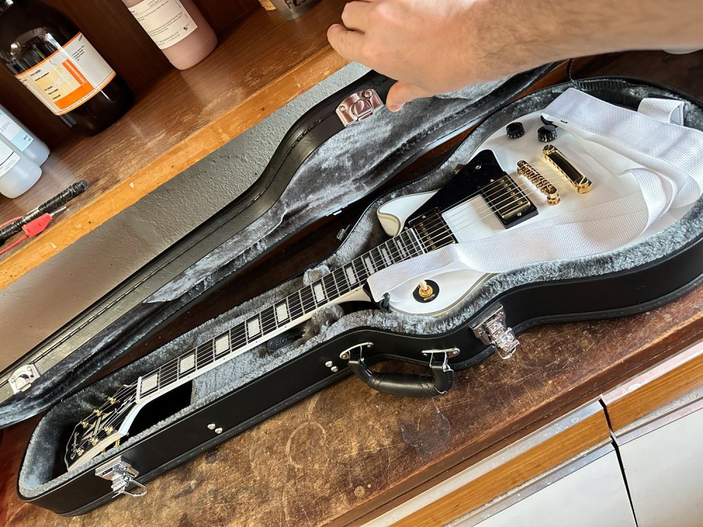
This up next?
-
This is my 'other hobby'.
A shit guitarist and proud of that!
-
7
-
1
-
-
4 hours ago, Clunkmeister said:
Phil, you got the screens, and the money we all paid him went to his Solicitor. When he gets out he might have changed his name to Francine.
But Ol’ Jay will be singing soprano like a bird.
Hopefully banged up with a guy called Leeroy and walking bow-legged afterwards!
The noncing sexual deviant.
-
2
-
-
Sweet Jesus
-
1
-
-
Good riddance to bad rubbish.
I always knew what a gold plated arsehole this guy was, but this adds a whole new element.
at least the turd is off the streets now, unable to abuse children or operate his dubious business.
-
3
-
-
I loved building the Fly Hurricane, but a proper, non-limited run kit is very much appreciated.
-
3
-


1/32 ME-262A-2a/U2
in LSM 1/35 and Larger Work In Progress
Posted
This looks like a carbon copy of my work, with that styrene rod section too.
I also had a lot of shrinkage in the outer shells and had to add card to it to make it all fit.