


James H
-
Posts
3,247 -
Joined
-
Last visited
Content Type
Profiles
Forums
Events
Gallery
Posts posted by James H
-
-
Ok, major update time!
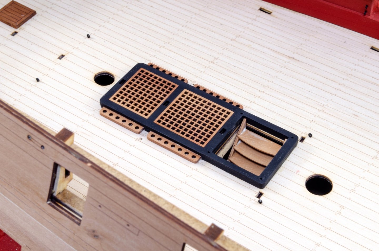
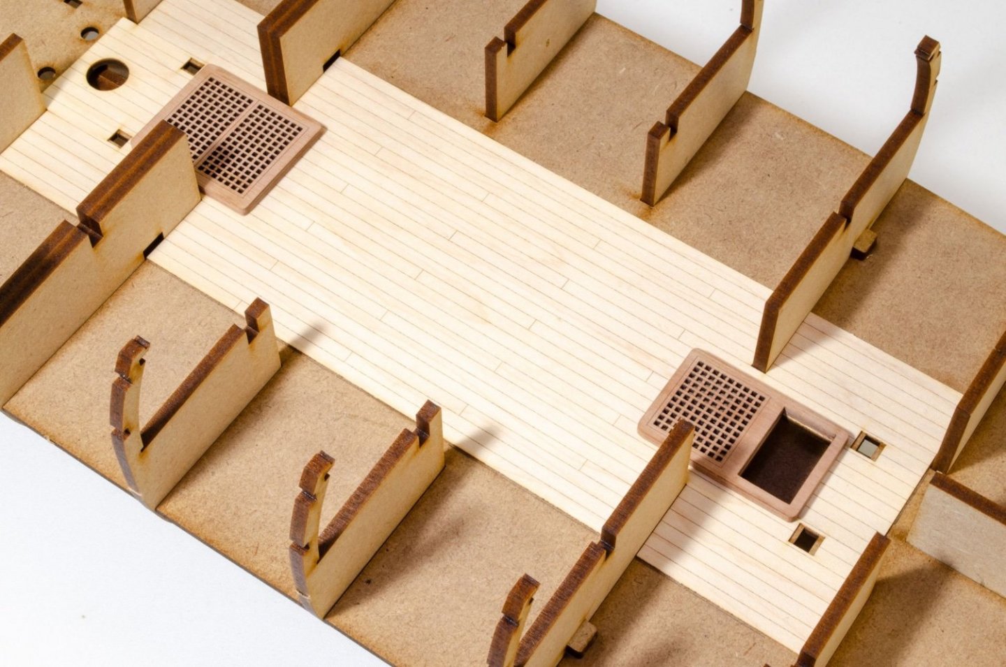
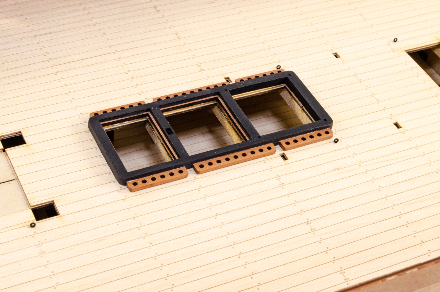
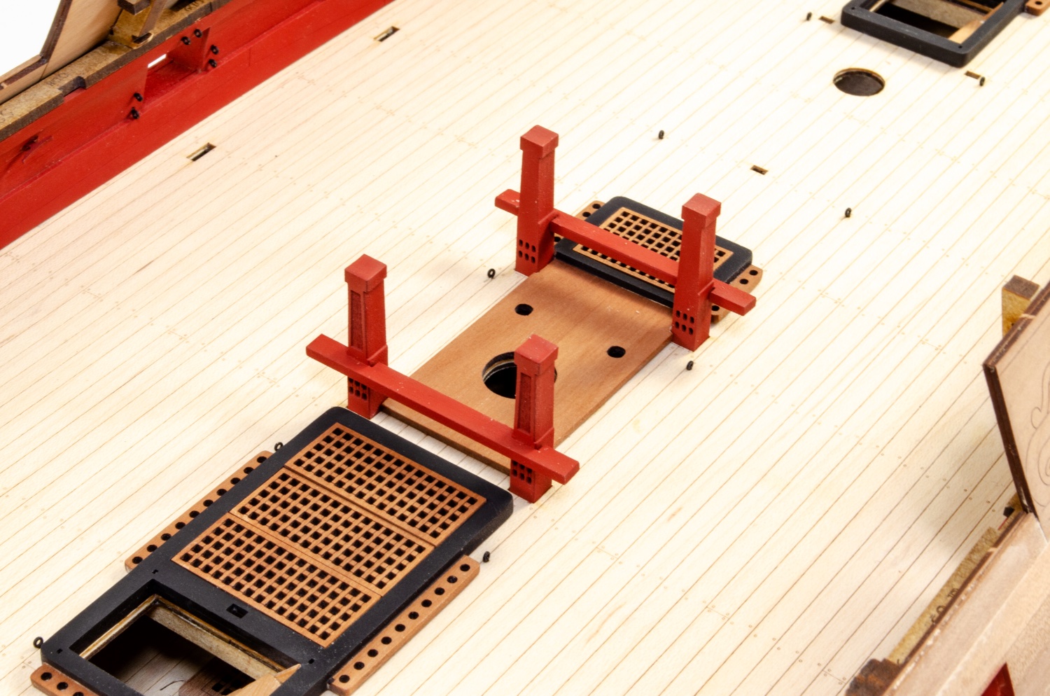
I've actually had a lot of subassemblies ready for a while, as this log shows, but now it's time for adding them in. What I haven't shown here is the spirketting that I added and fitting the eyelets to the inner bulwark gun positions. You'll have to wait until manual is finished for those! I've had to take about 100 photos these last days and sequence them, with the ones I took ages ago. Ok, first paint is for the coamings, after masking off the garlands and glue area for grates.
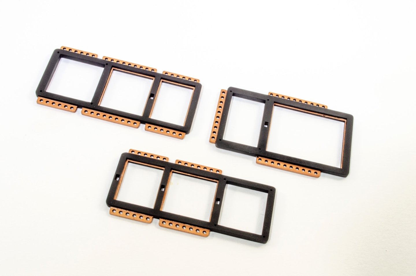
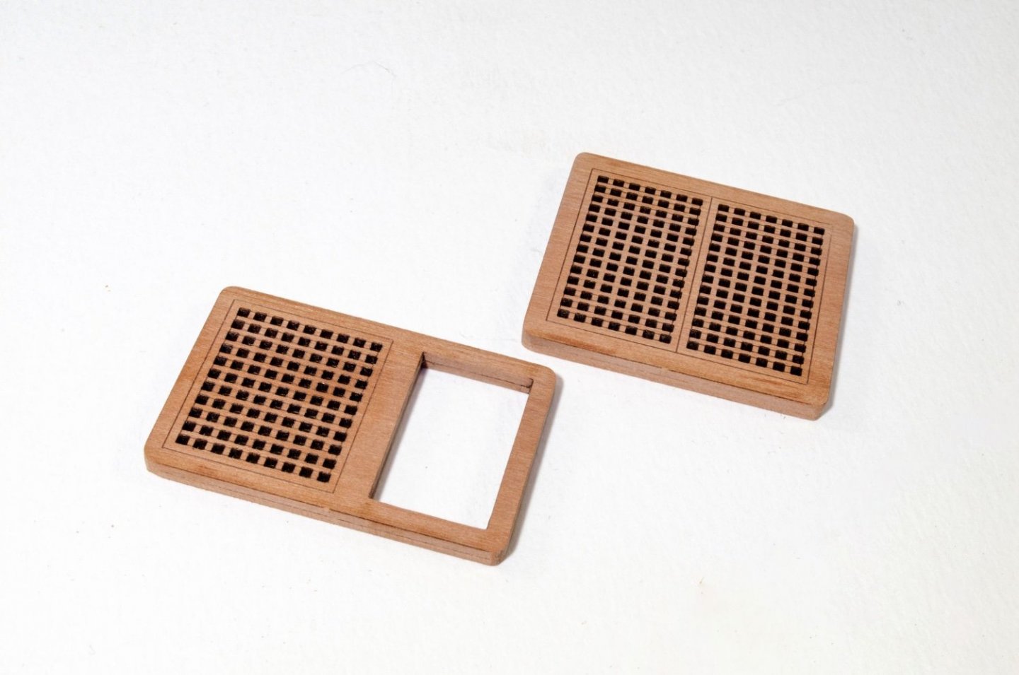
Coamings now fitted without grates as they are more flexible for deck curve.

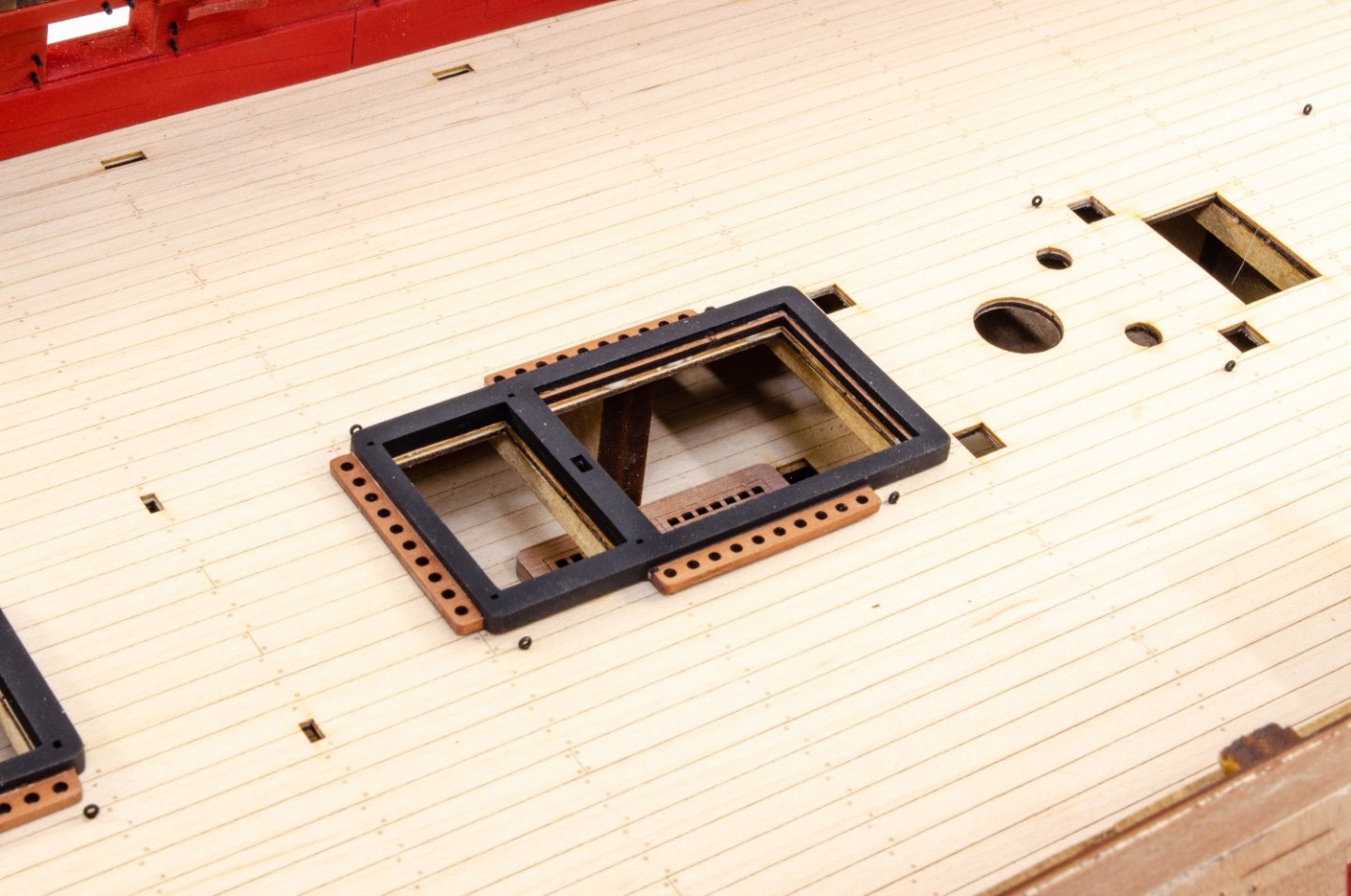

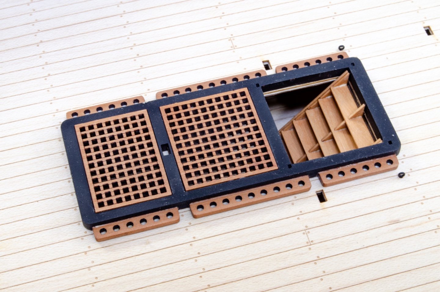
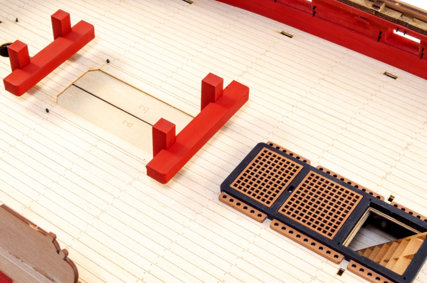
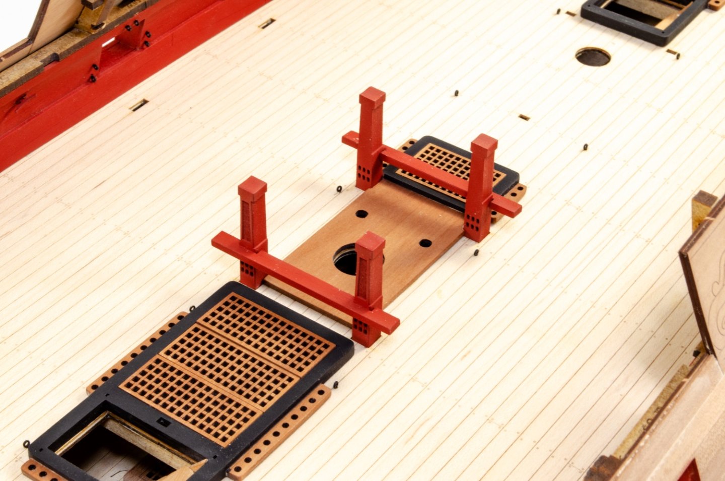
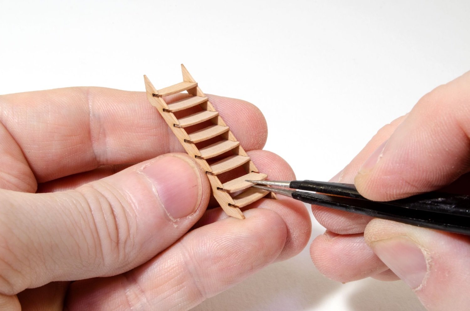
I've probably posted this pic before, but this just shows that the ladders are now being fitted, along with the grates.


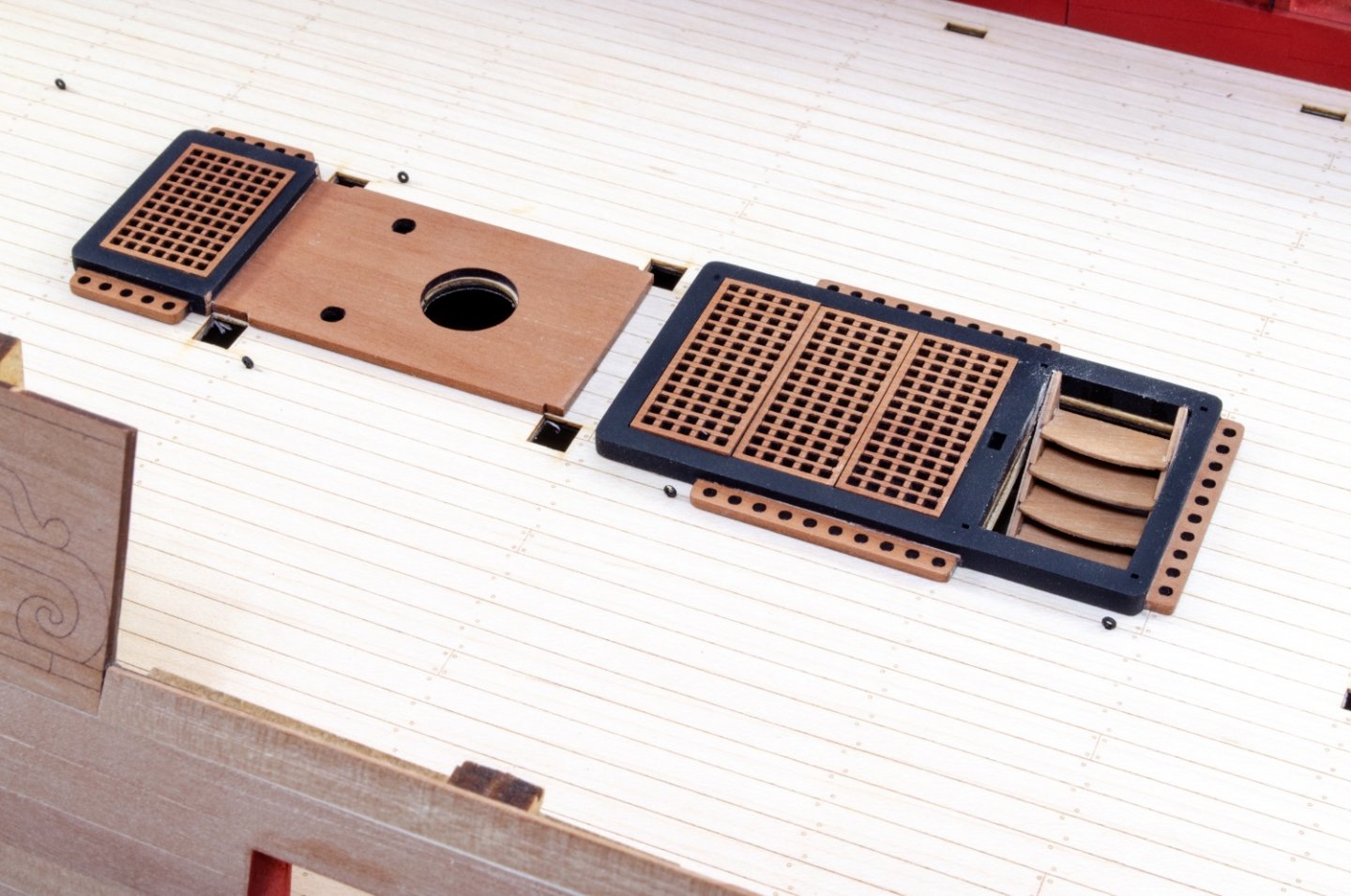
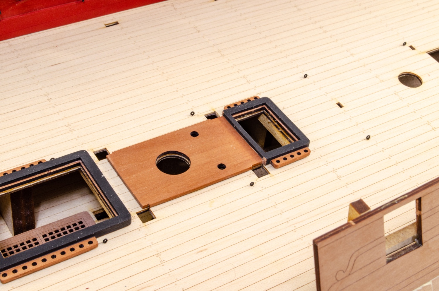
I pre-assembled the bitts etc in situ, then removed them when dry before painting. These are now added into place for the last time.
-
 5
5
-
-
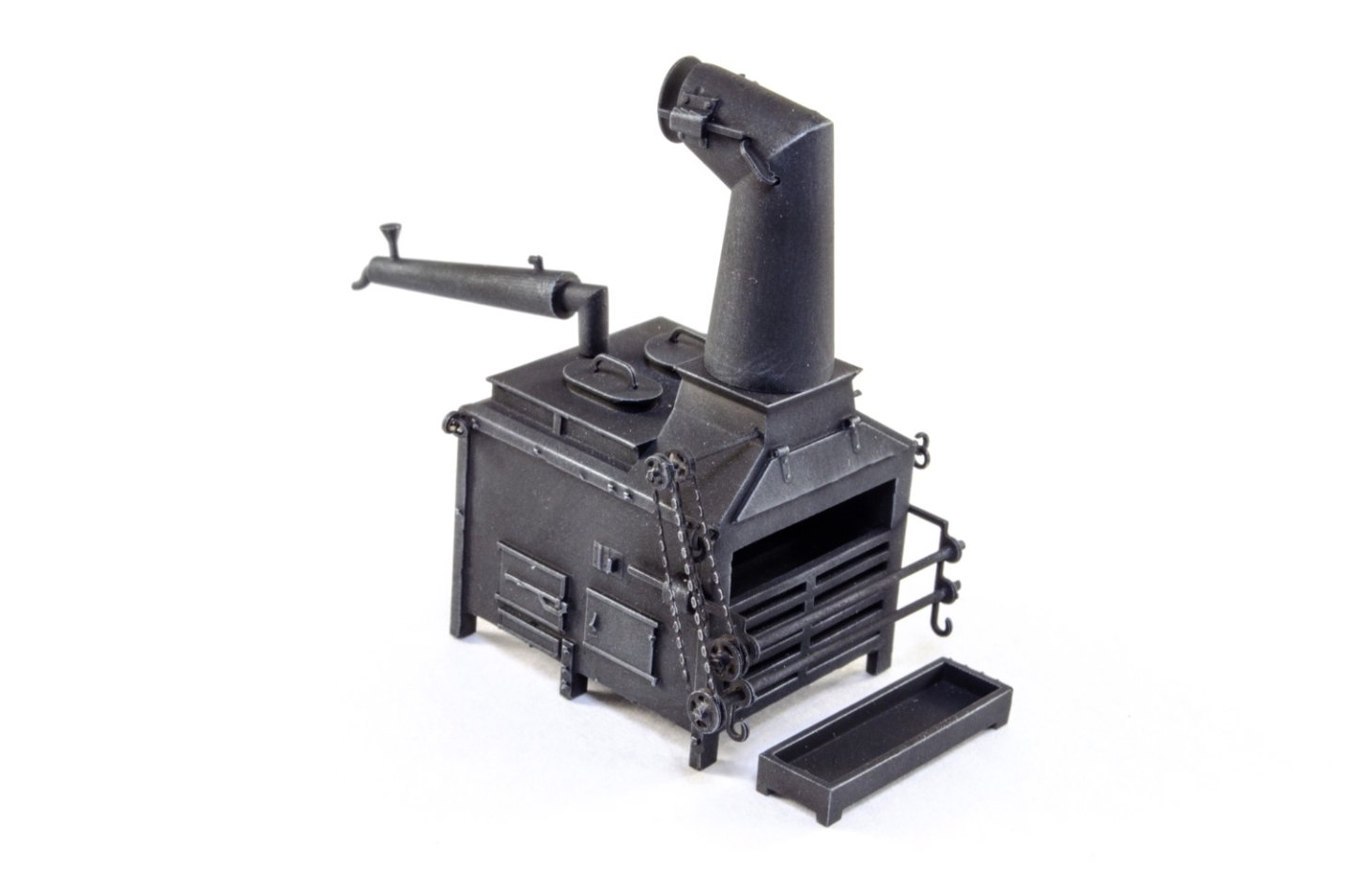
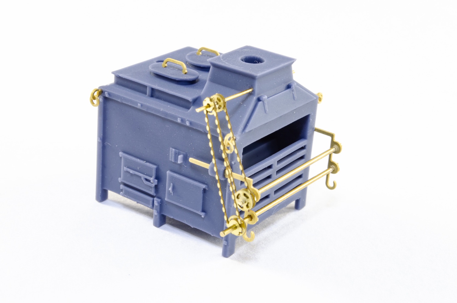
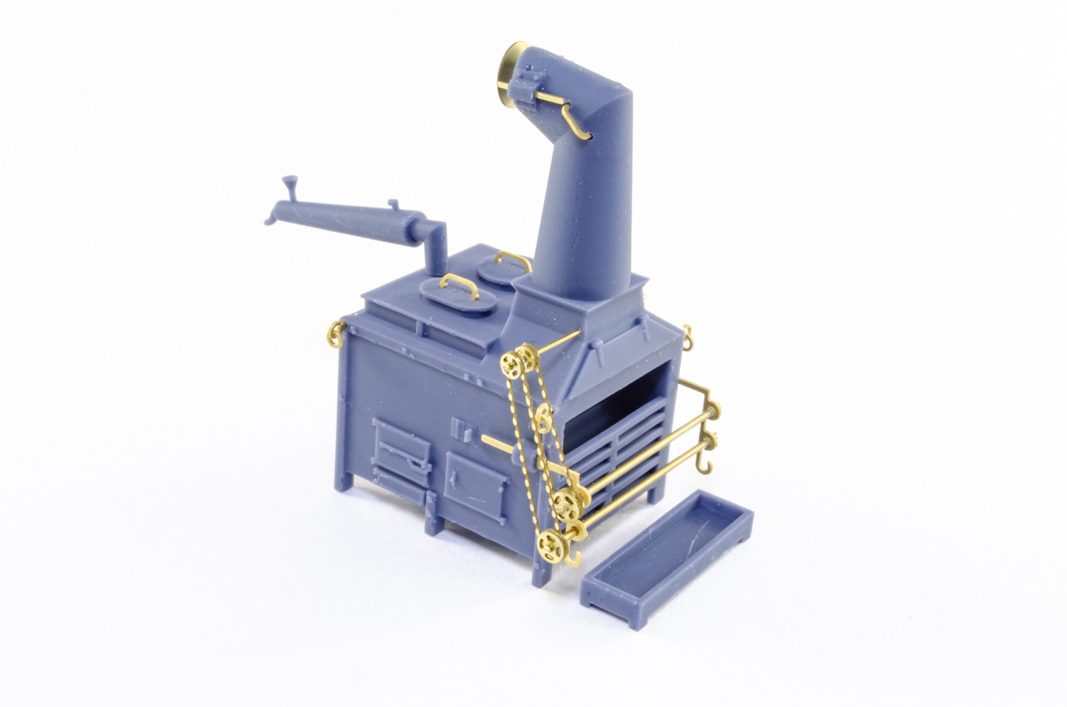
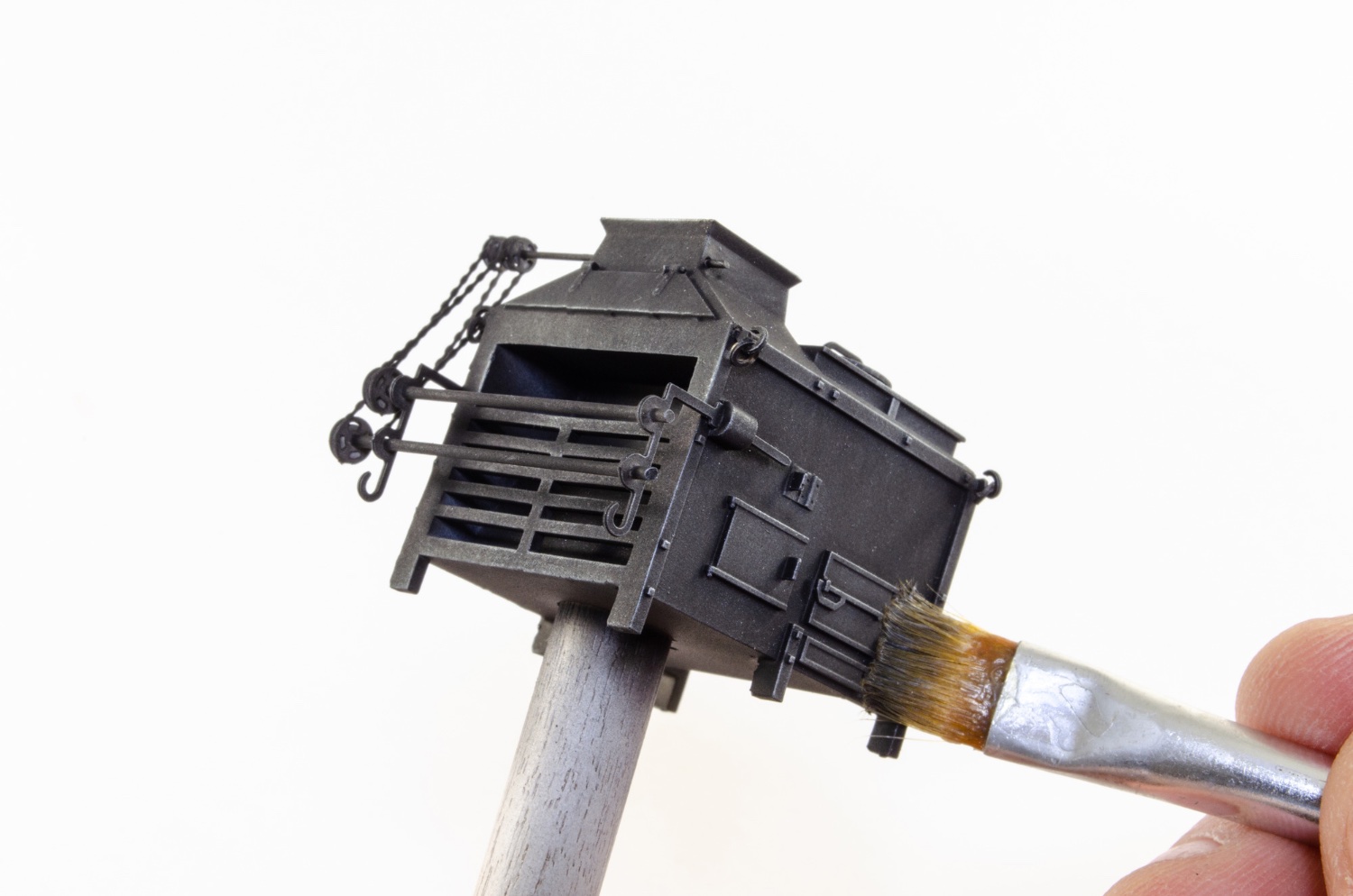
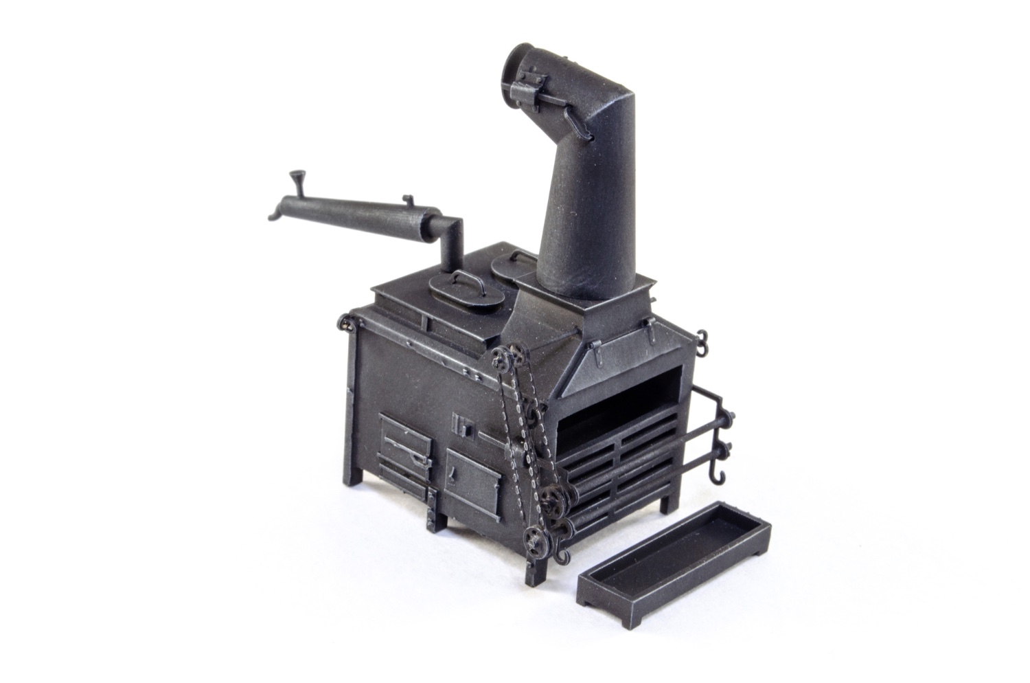
Ship's stove.
I know I did the for the VM web-shop but this one is now printed in 8K resolution using a different resin which is tough. There are two PE frets with this stove, with a few spares for things like pulleys and eyelets etc. The stove assembly is the same as the one in the shop, but here are some pics of the work.


Tamiya fine primer was used on the stove, followed by Tamiya Flat Black. The stove was then weathered with Uschi van der Rosten steel pigment. At this stage, the chimney and pipe are only sat in position. They'll be glued to the stove later in the build.

-
4
-
-
Tiny update as I am doing a few other things in other build areas of Indy too.
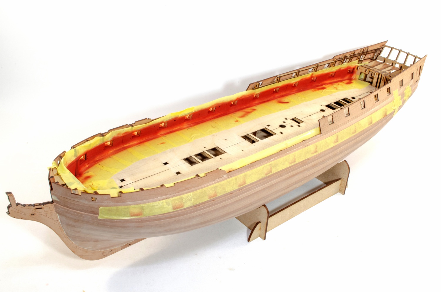
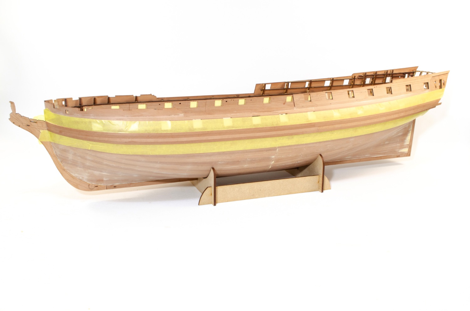
I now have some colour on the model. I first varnished the exposed strip on the inner bulwarks and then used masking tape before I added paint. For this, I used some Plastikote Red Oxide (same as on the lower fisher hulls) and decanted it from the aerosol so I could airbrush it. The paint was left to de-gas for a few hours. That's important as it'll boil if you try to use or do anything with it when fresh from the rattle can. The paint was then thinned with mr Levelling Thinner, about 60:40 paint to thinner. When completely dry, I airbrushed Tamiya Flat Red over the red oxide.
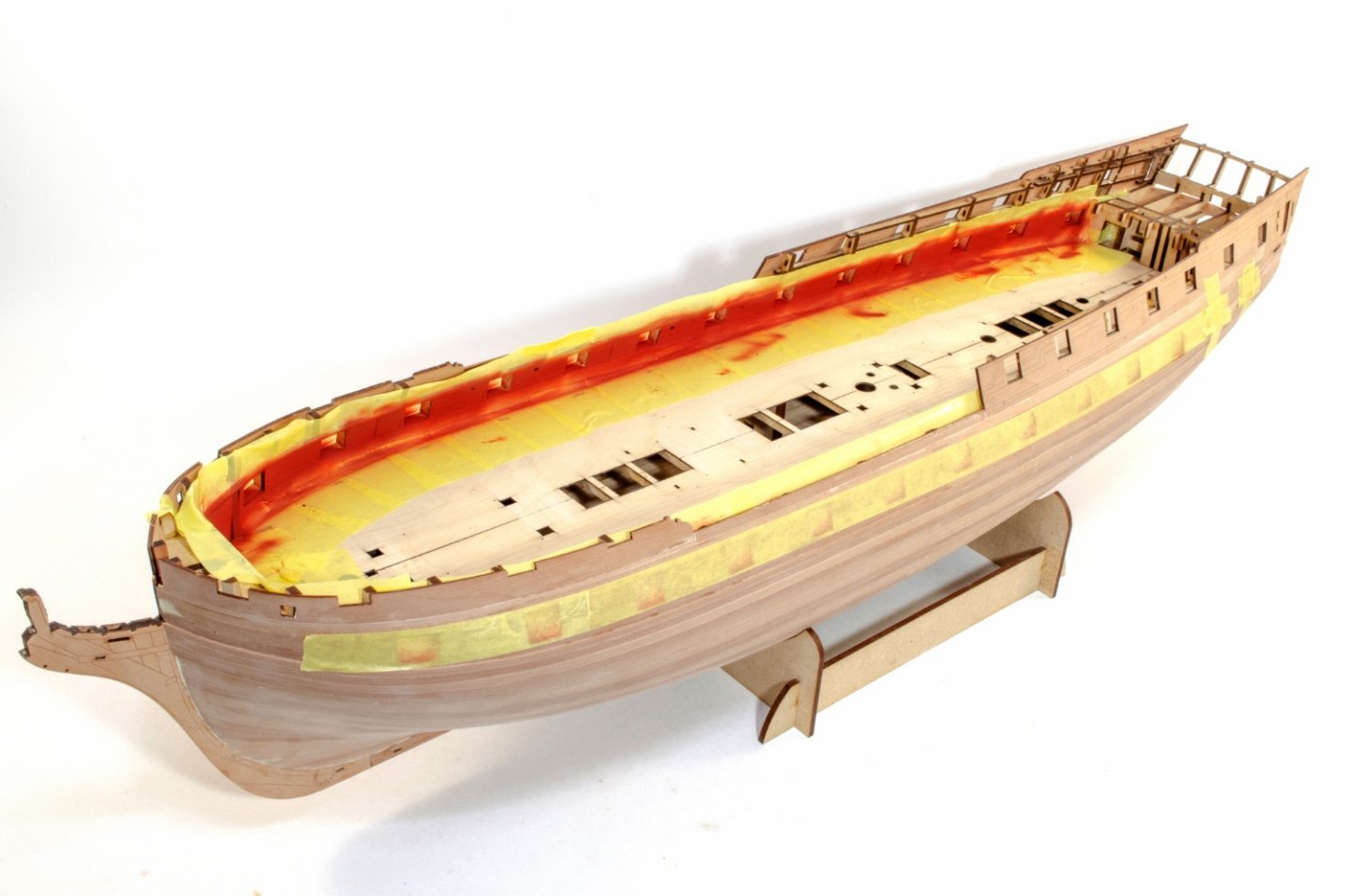
After more judicious masking (and masking the ports off from interior), I did the same paint regime for the gun ports. Once dry, everything was unmasked.
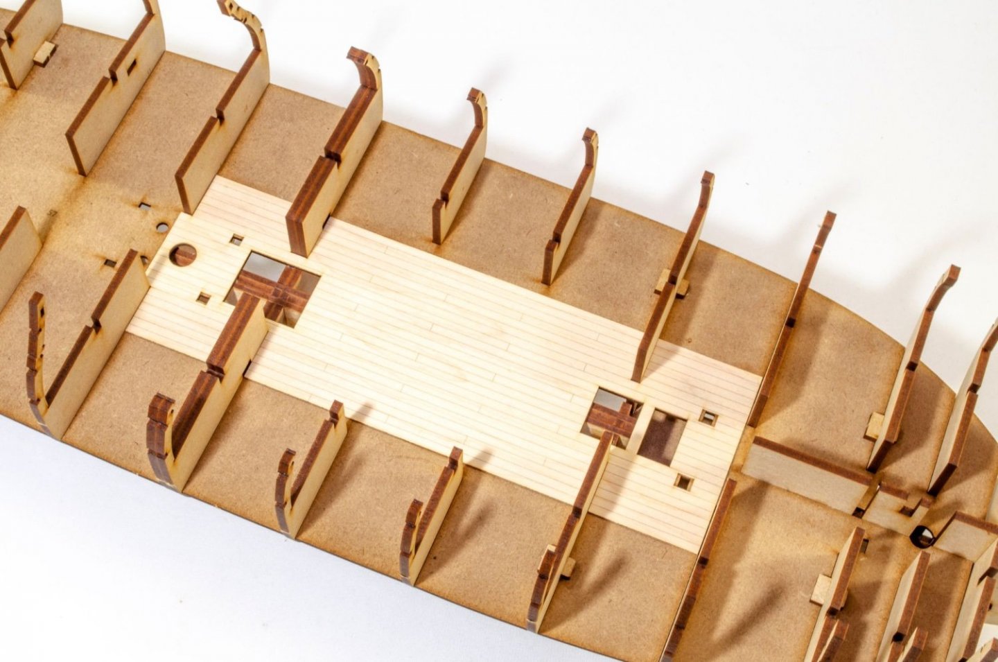
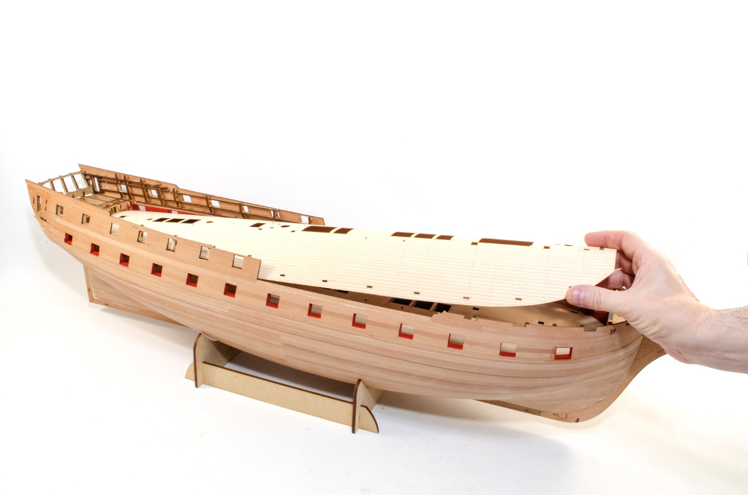
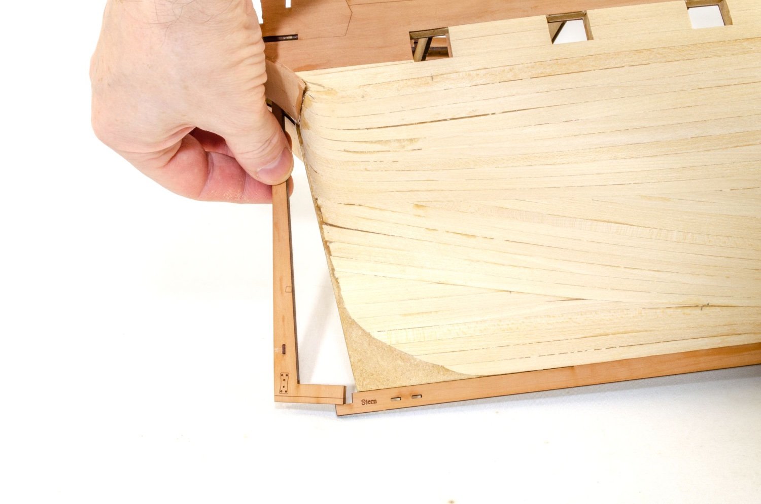
The standard kit will be supplied with Red Alder for deck planking. This is a beautiful timber. However, for this, I am using an engraved maple veneer deck. There will be an option for a maple deck, but it's an actual maple deck, not veneer. Fitting the deck will be the same as for this, with a subtle flex and sliding into the rear first, underneath the stern timbers. First though, a test fit should be done and the edges sanded so it lies flat to the bulwark edges.

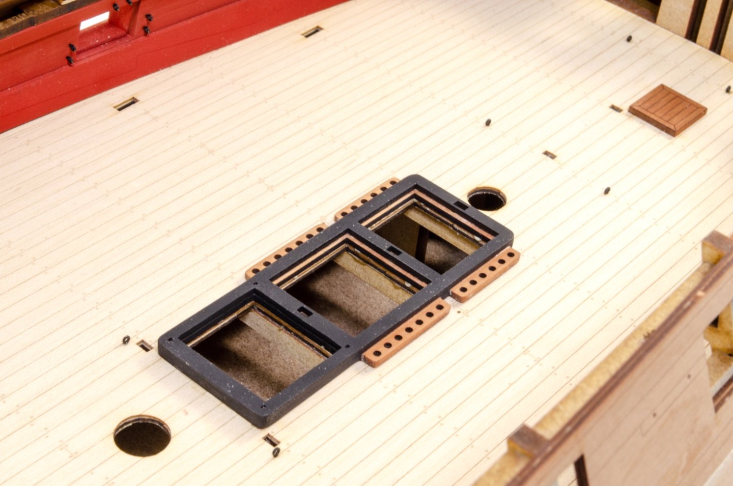
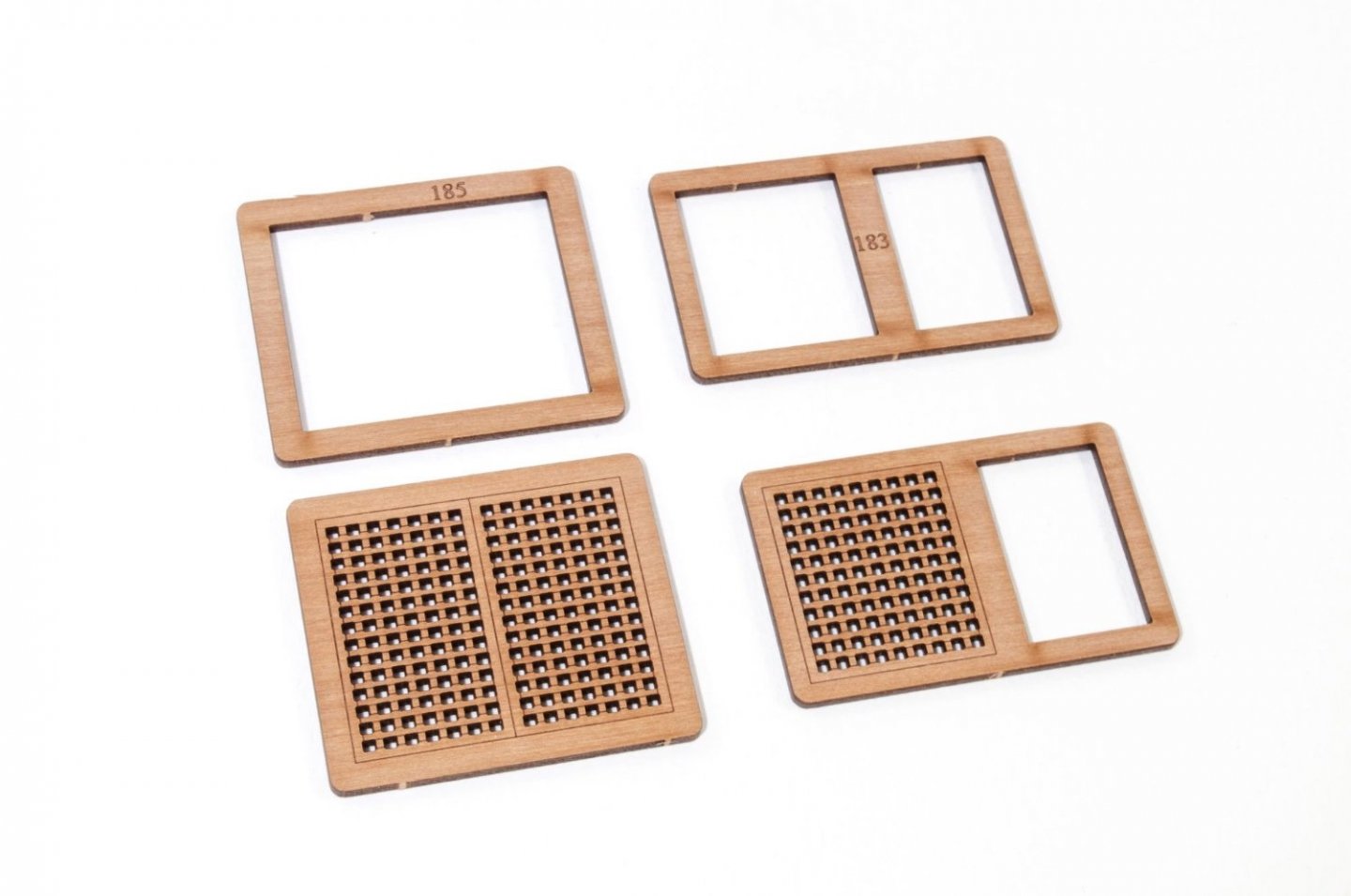
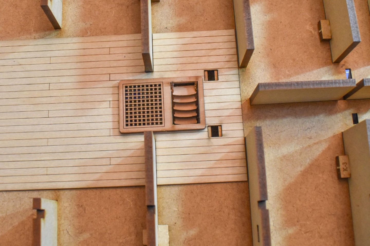
The deck was then glued down and left to dry. In the meantime, the main gu deck coamings were masked and airbrushed in Tamiya Flat Black. The grates will be added after the coamings are fitted, so to reduce rigidity when fitting.


More soon(ish)
-
4
-
-
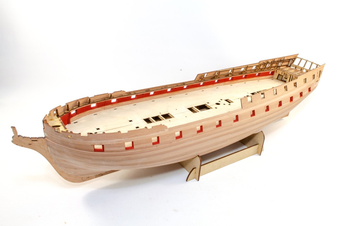
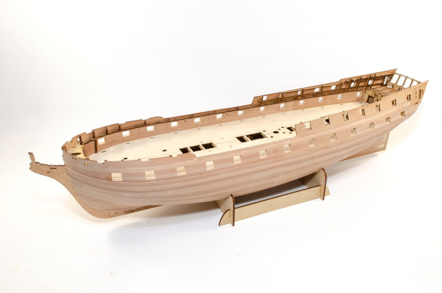
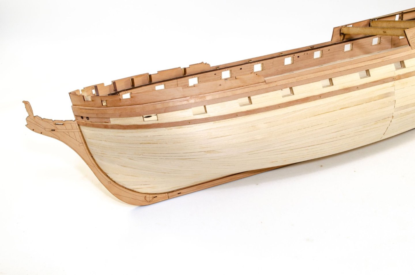
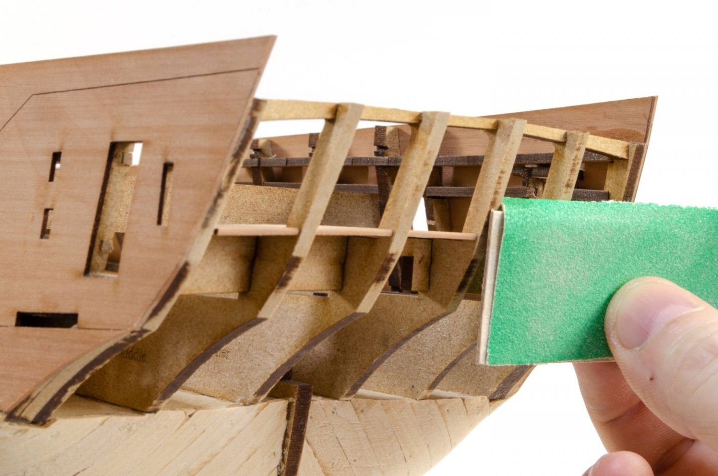
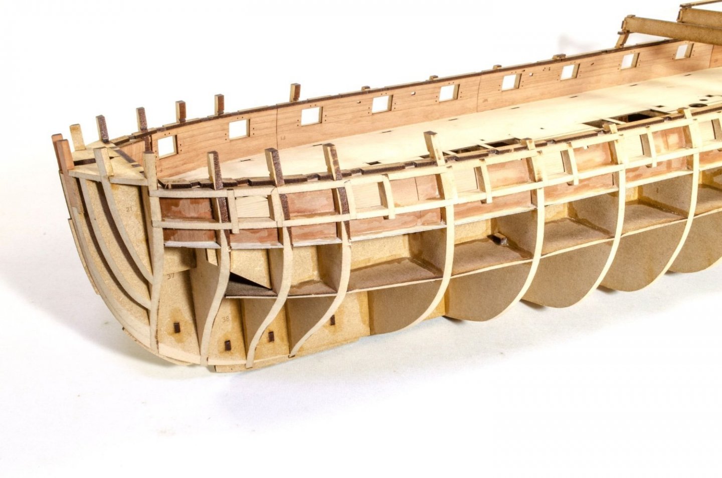
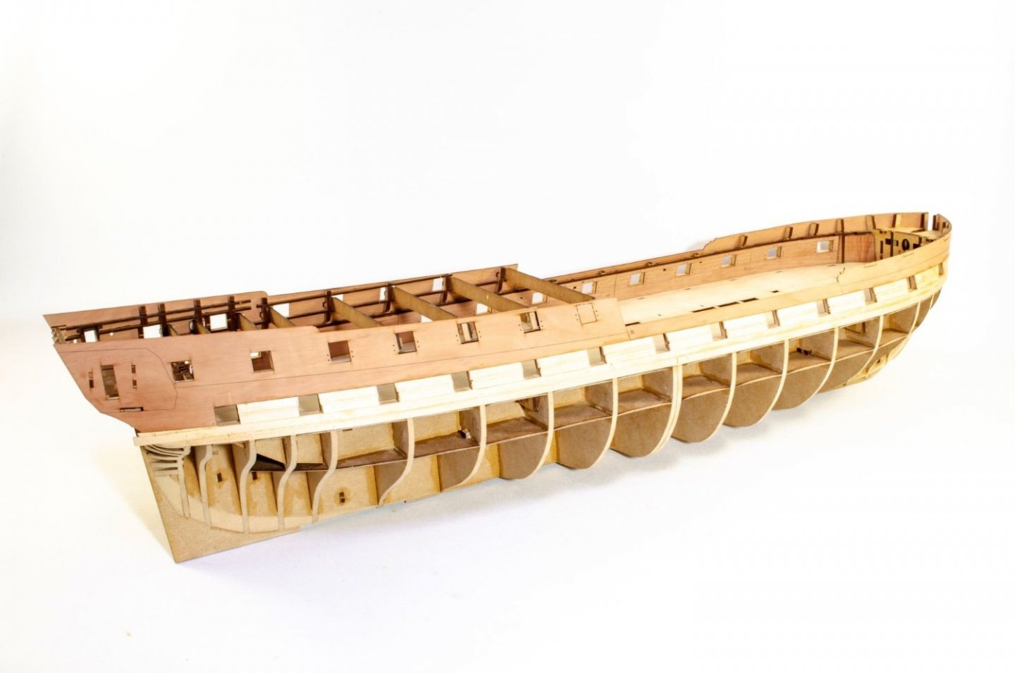
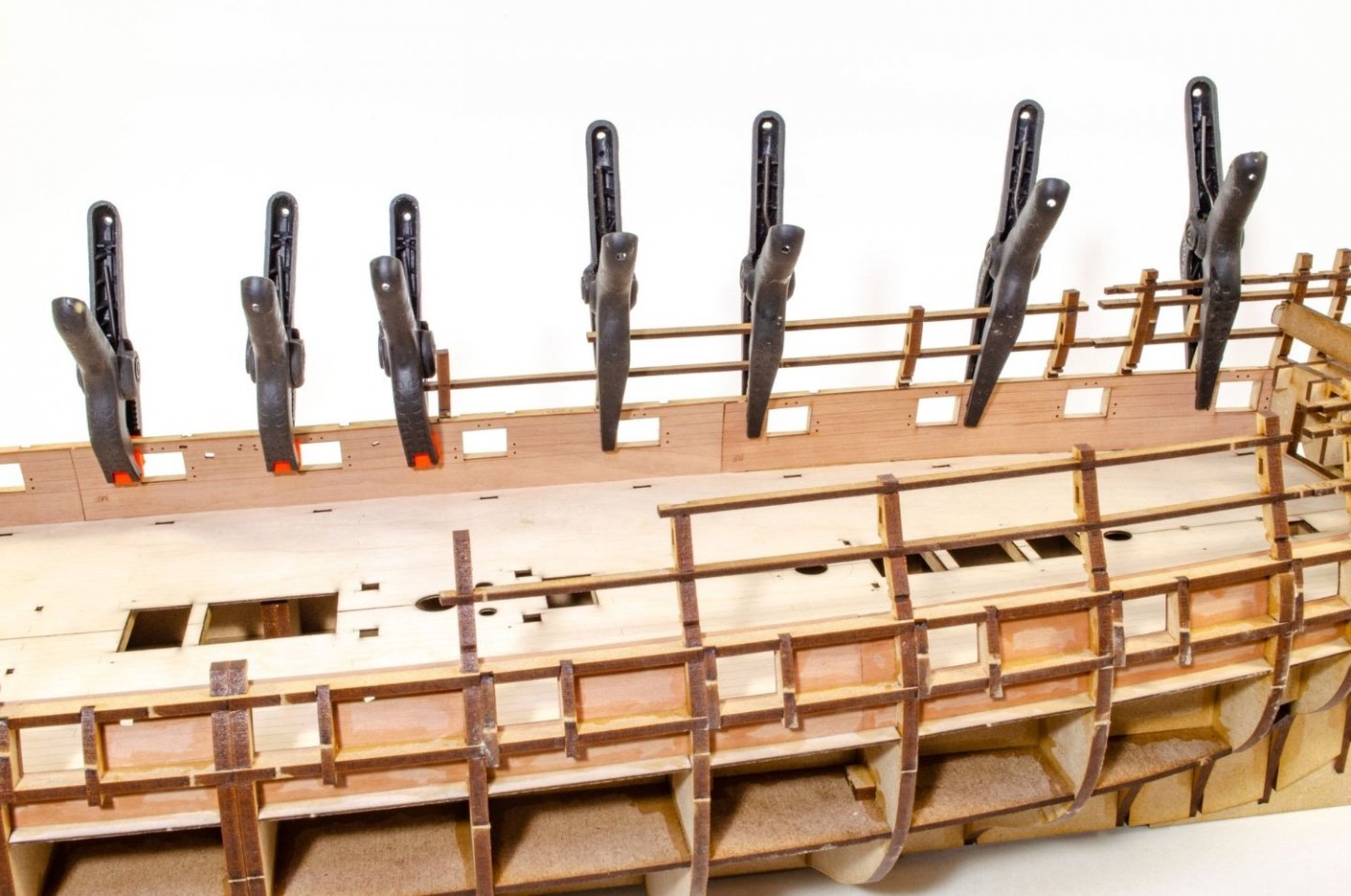
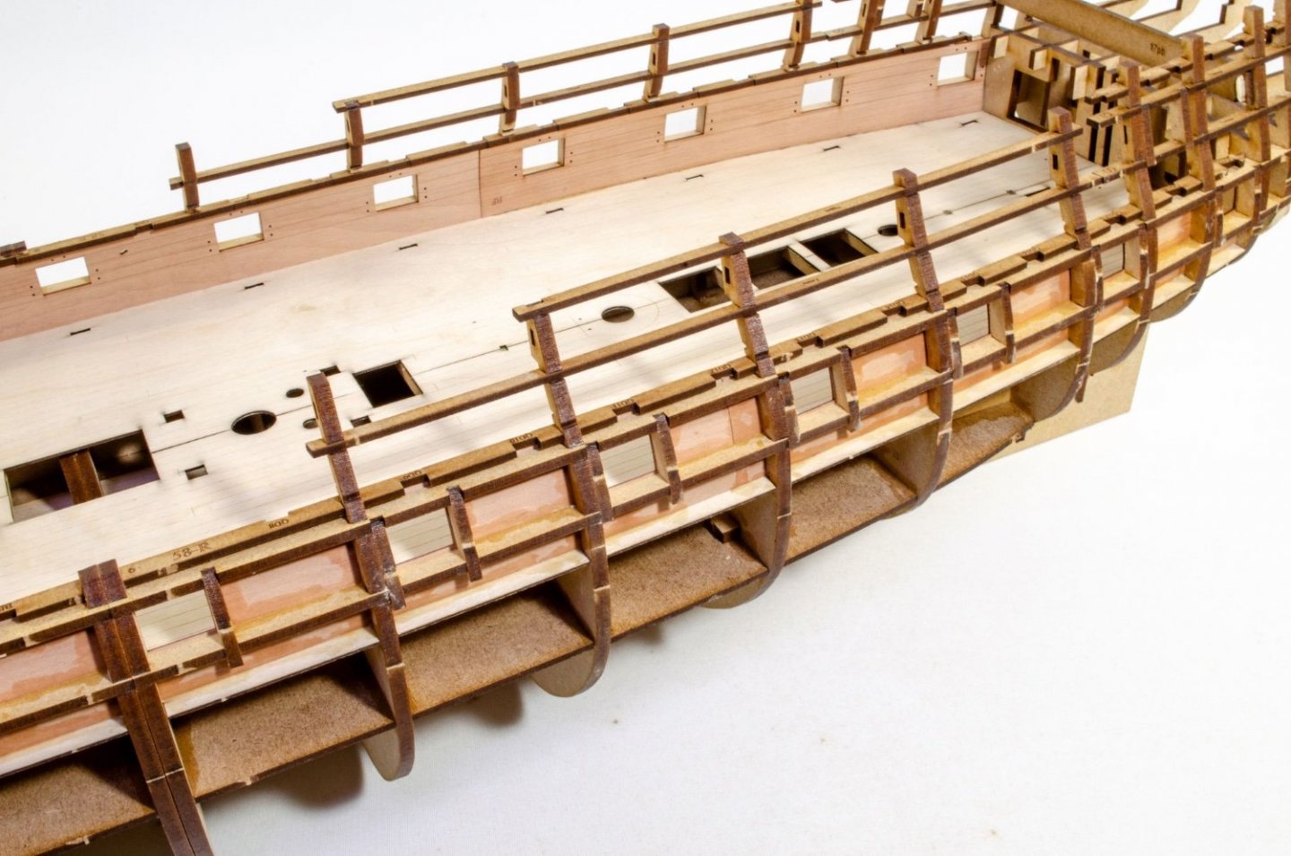
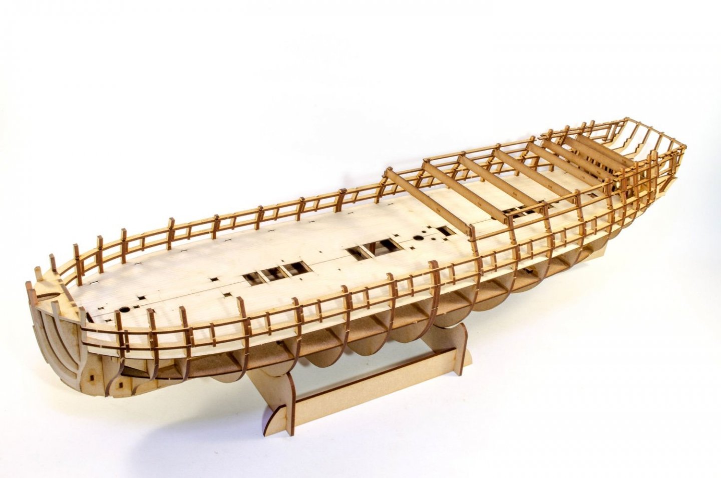
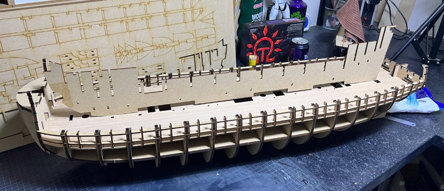
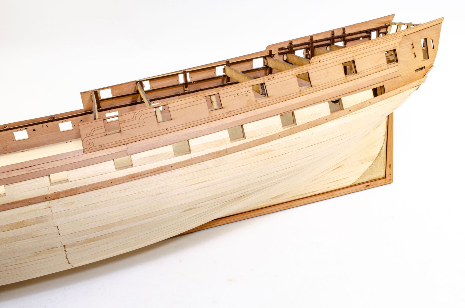
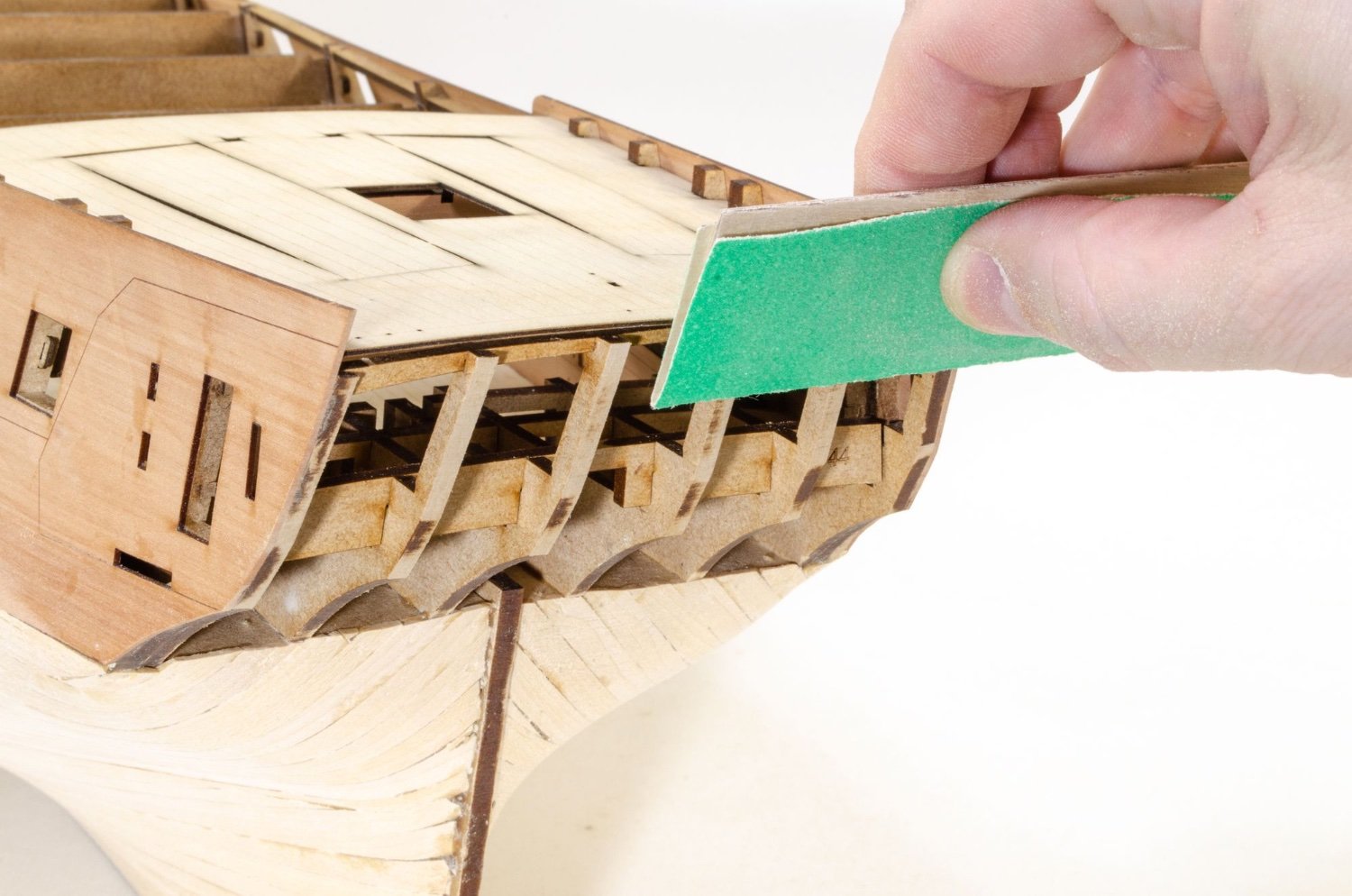
This update shows the basic external finishing of Indefatigable, and at this stage doesn't include the numerous rails etc. that make up the side bulwarks. That's for later in the build.
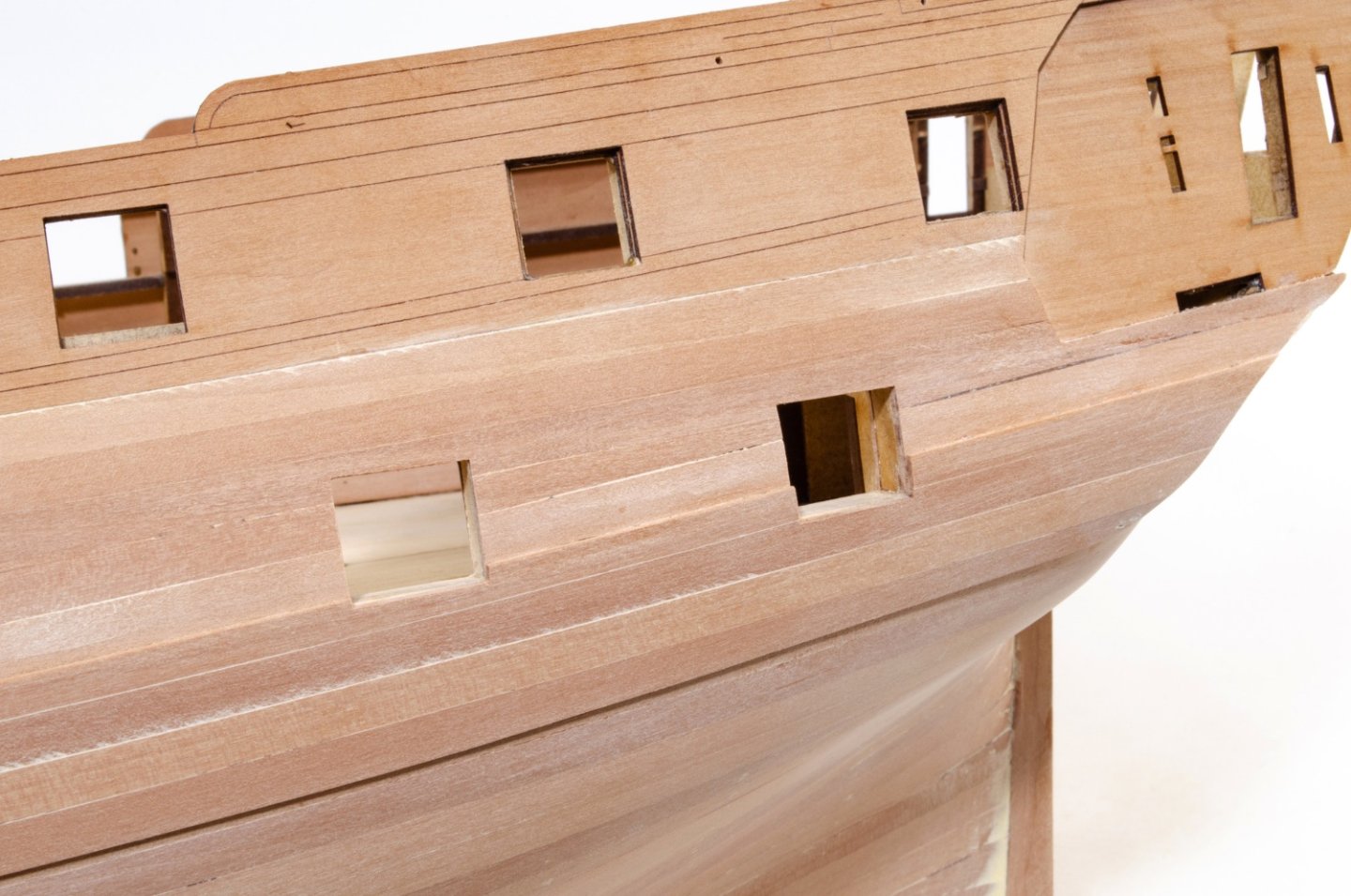
After a LOT of sanding of the second pear planked layer, the gun ports were opened up to their correct size at last. Before using some custom-made sanding sticks for the job, the inner bulwark port openings were trimmed down more or less to the size of the port itself. The sanders were then used to finally clean them up and even out the internal areas. A sharp scalpel was then used to square up any corners properly.
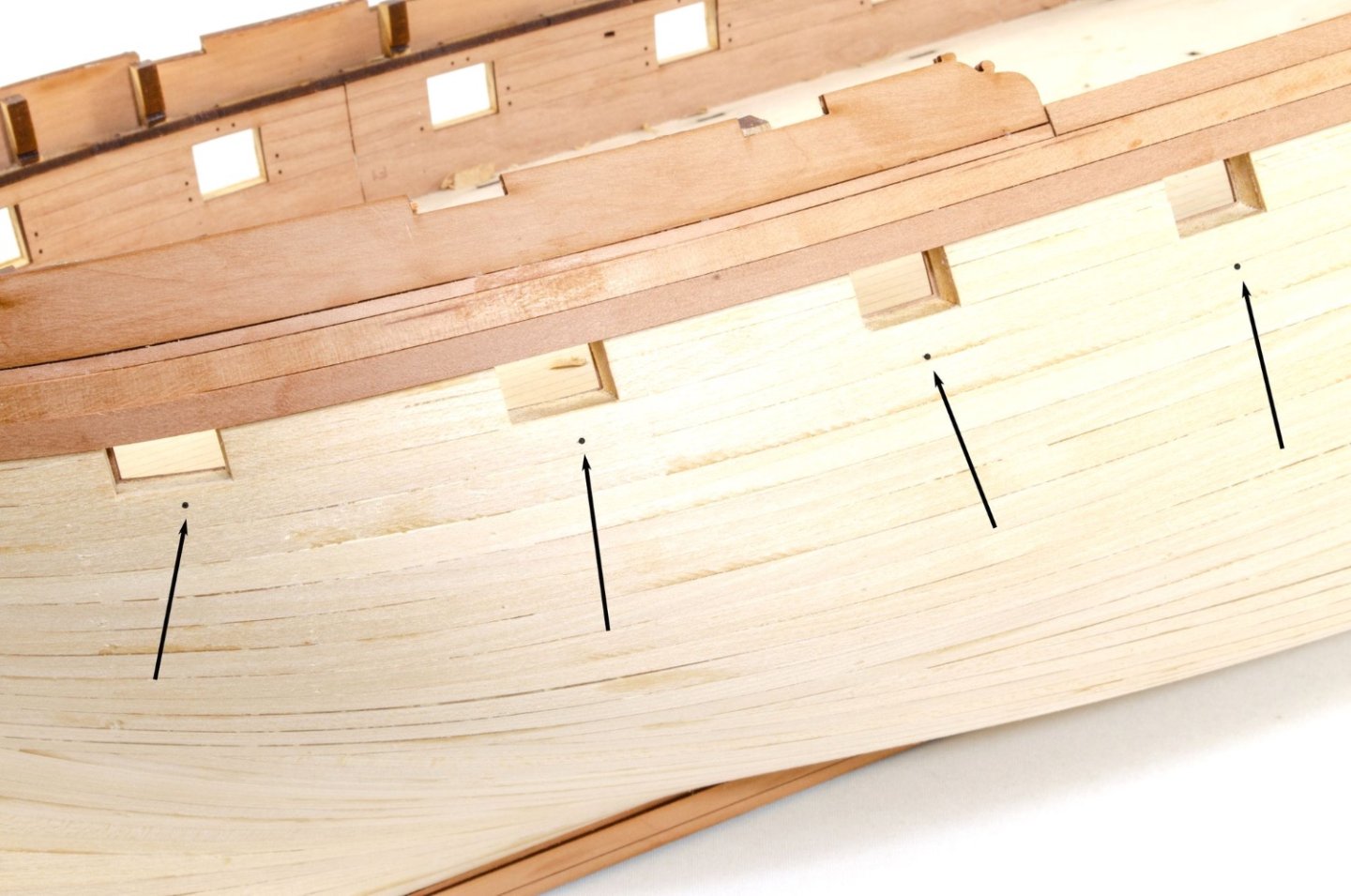
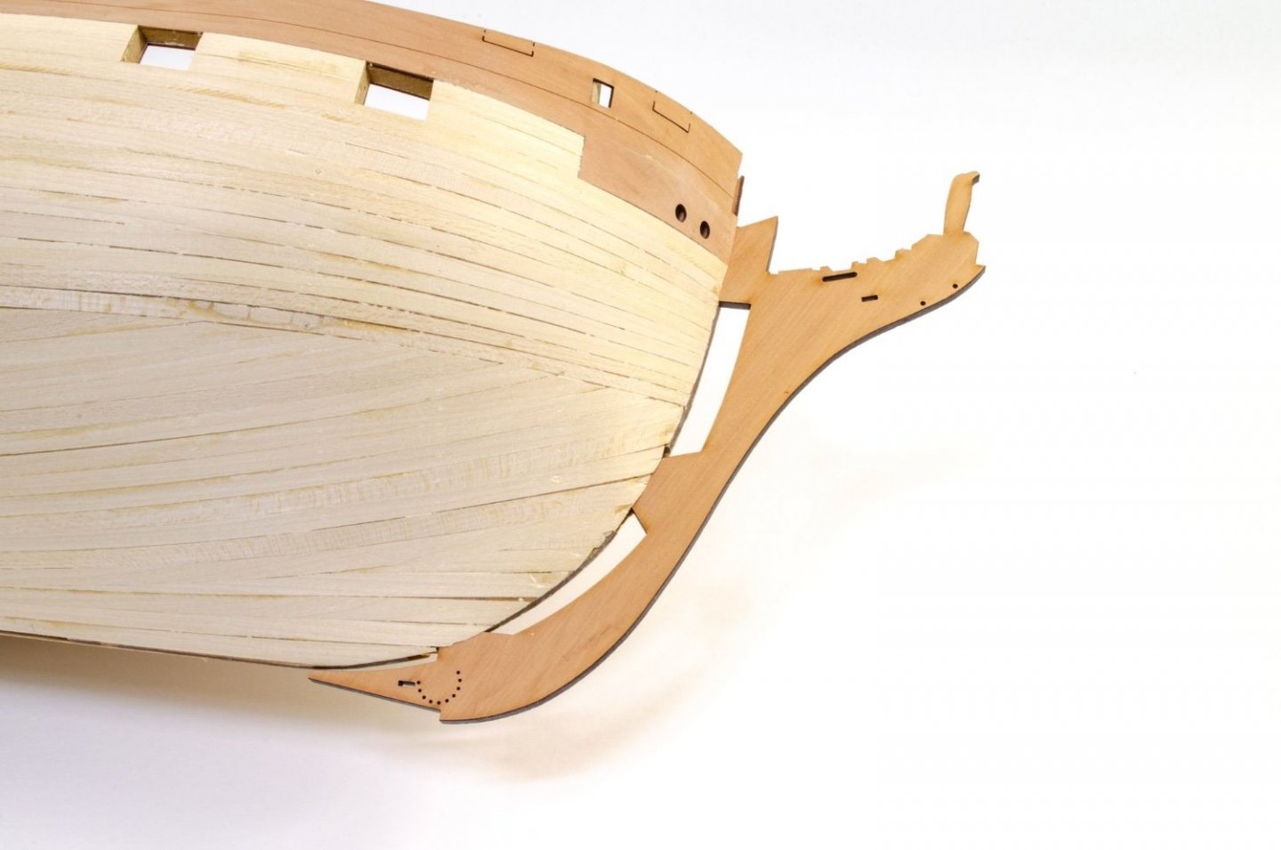
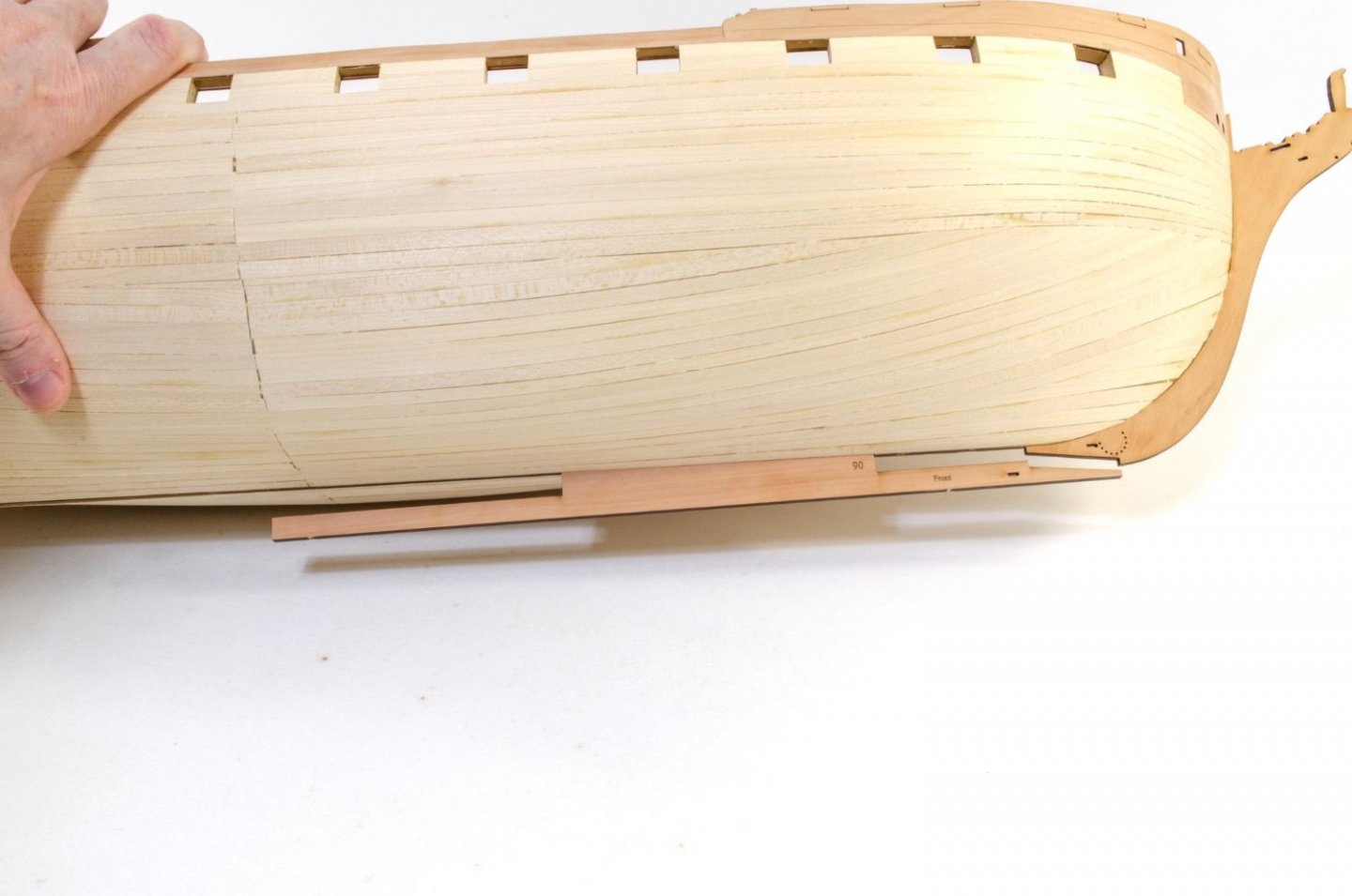
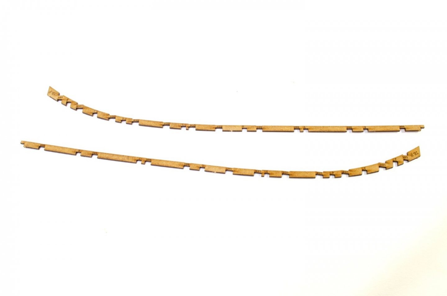
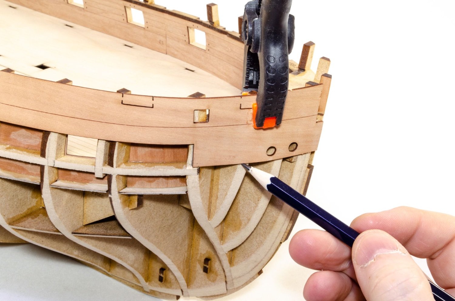
If you remember, the first pear plank was laid to be in the exact same position as the the upper strip of the wales. Here you can see the mark that indicates the flow of the plane at the prow. The top also aligns with the top of the prow, so that makes it easier!
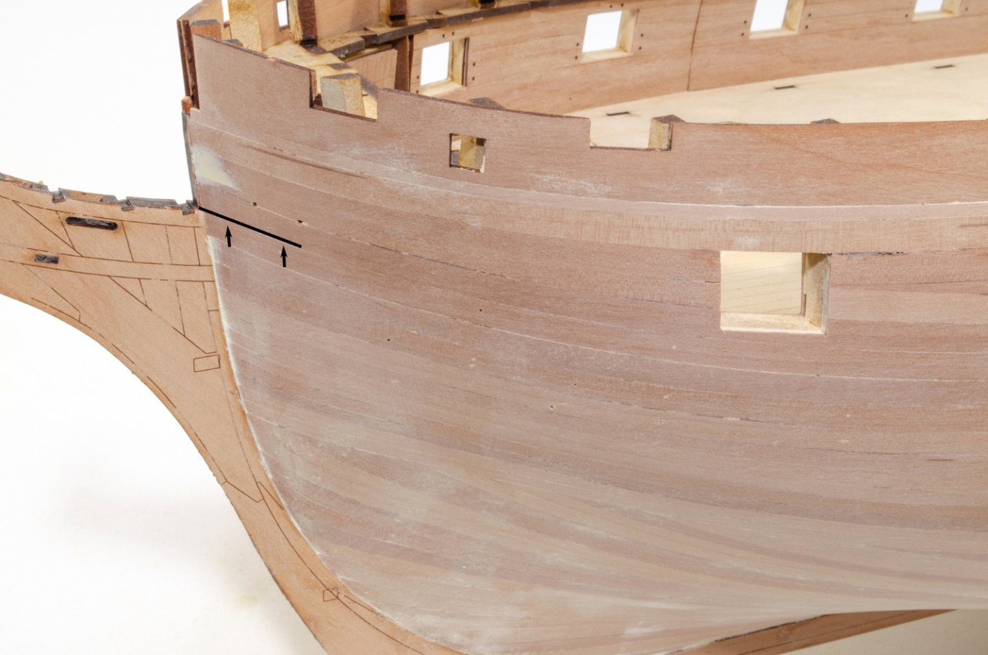
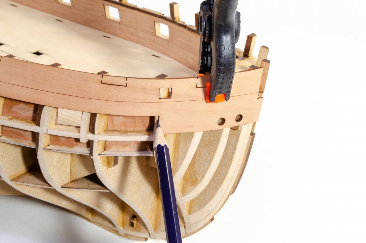
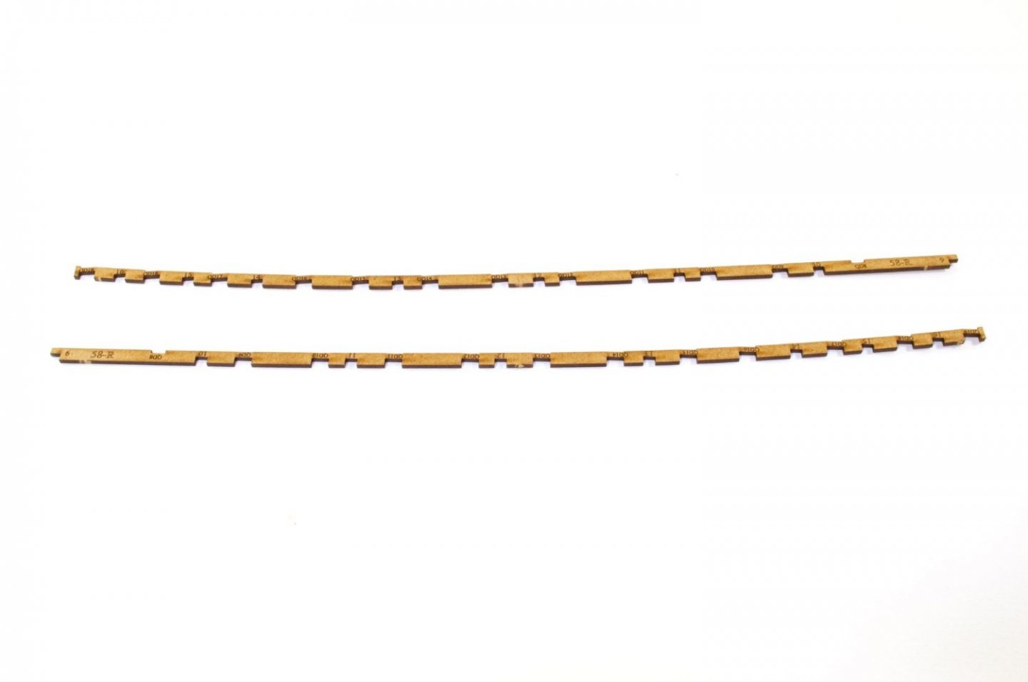
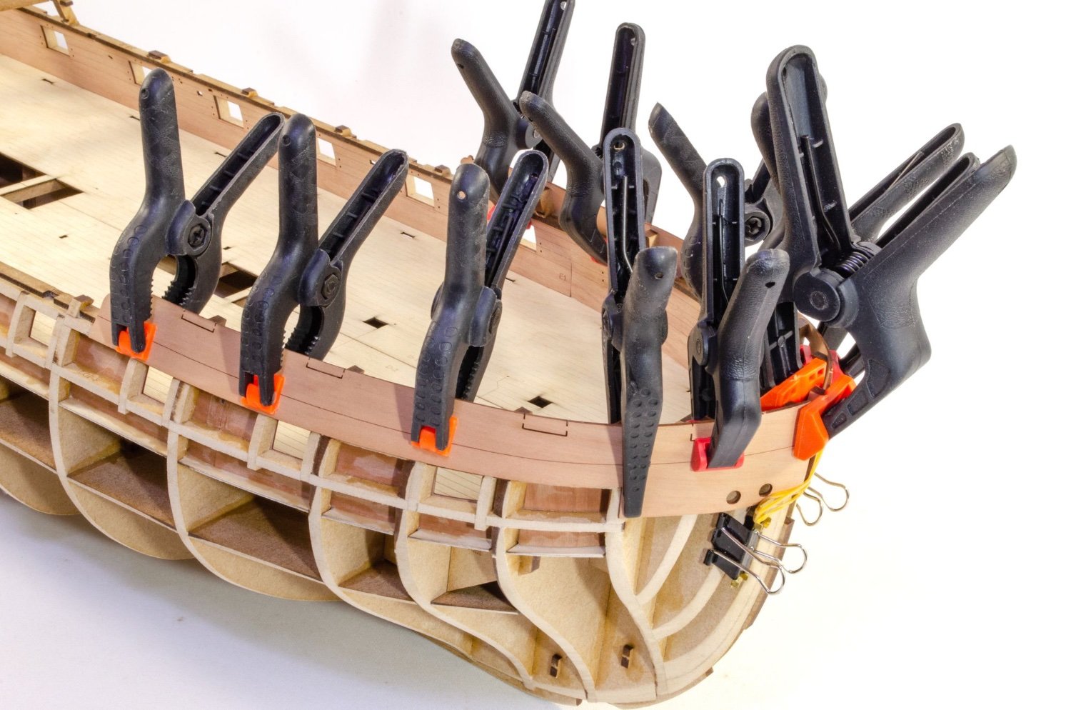
A 4mm wide strip of 1mm pear is now run from the prow to the stern, following that plank line. I used CA gel for this as I didn't want to use any pins on this area. I've left the plank overlong at the rear so you can see where it runs to. The last two gun ports are also partially obscured by the strip.

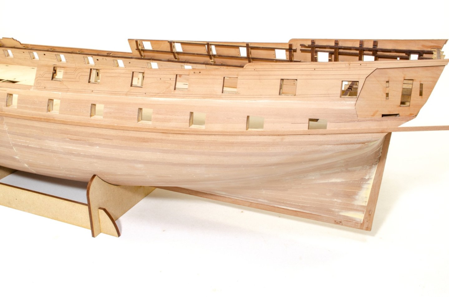
Now, three 5mm wide pear strips of 1mm thickness are run directly underneath the 4mm strip, again with CA gel. Once in place, I masked off the area on both sides of the wales and sanded the wales smooth. You'll note that I tapered the lower two planks towards the bow, and the lower one plank at the stern.

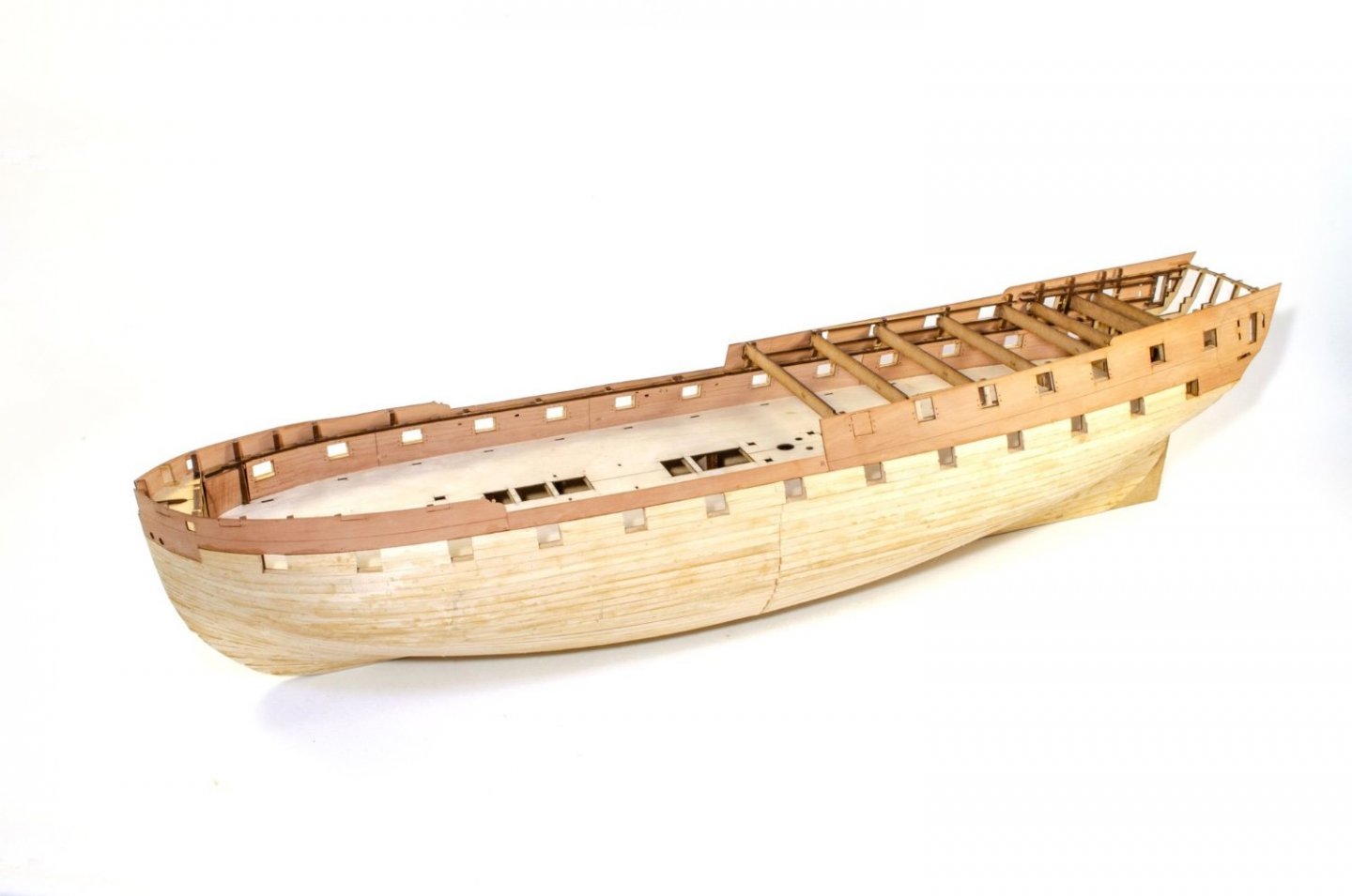
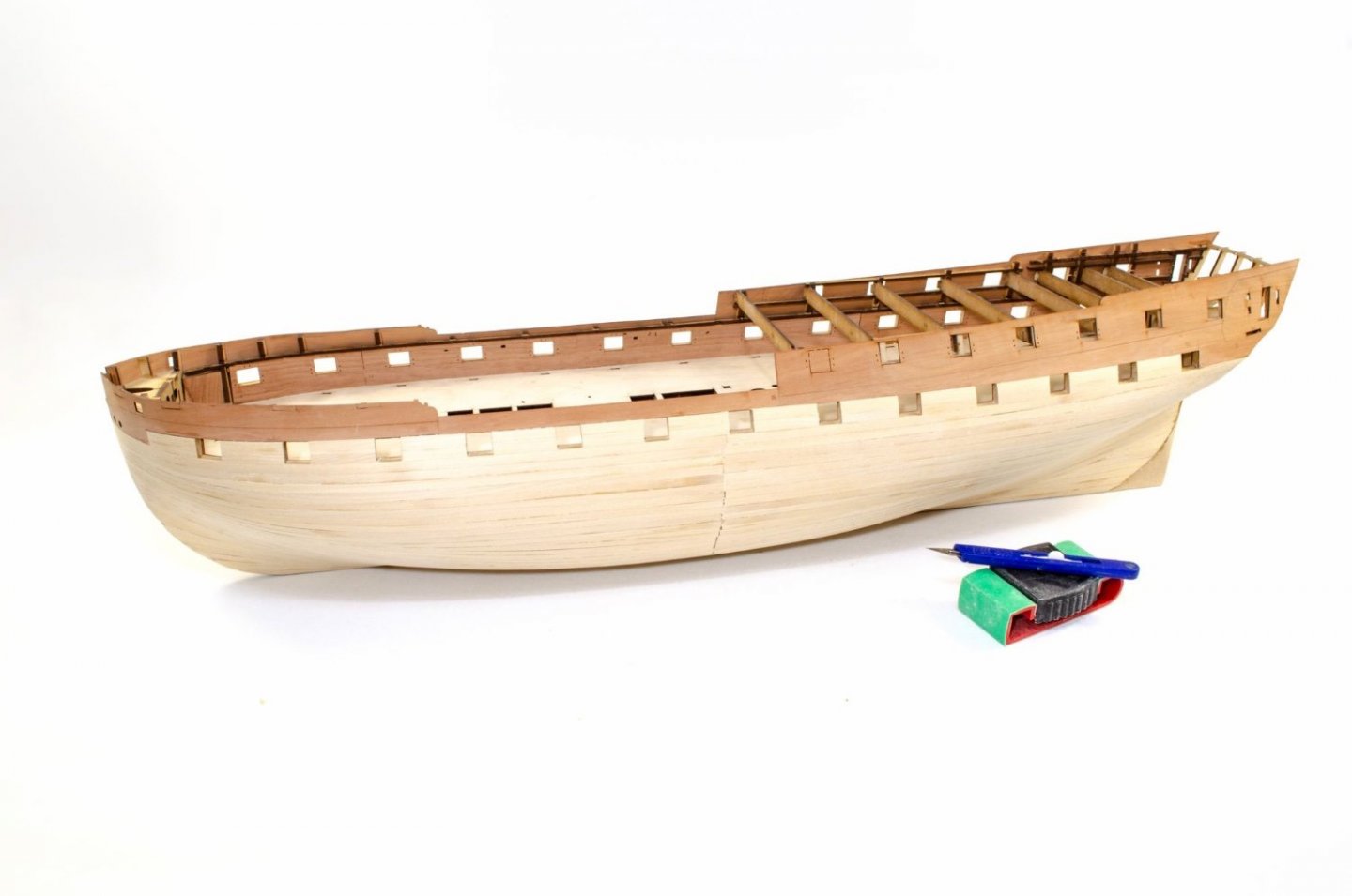
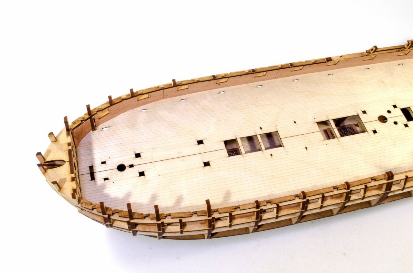
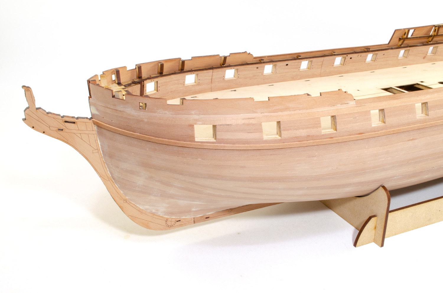
The gun ports are now cut into the wales, and the wales are finally shaped at the stern. These are shaped from the curve of the stern lower counter, and rounded into the underside of the wale.
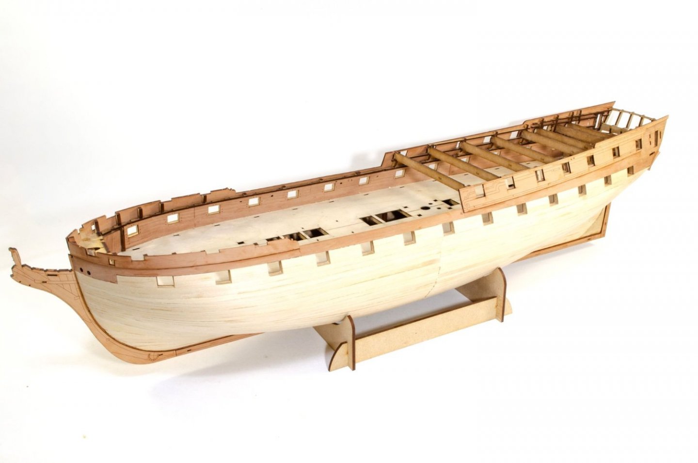
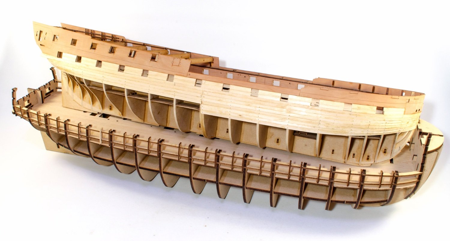
Indy now looks like this. The next update will show some internal work underway.
-
5
-
-
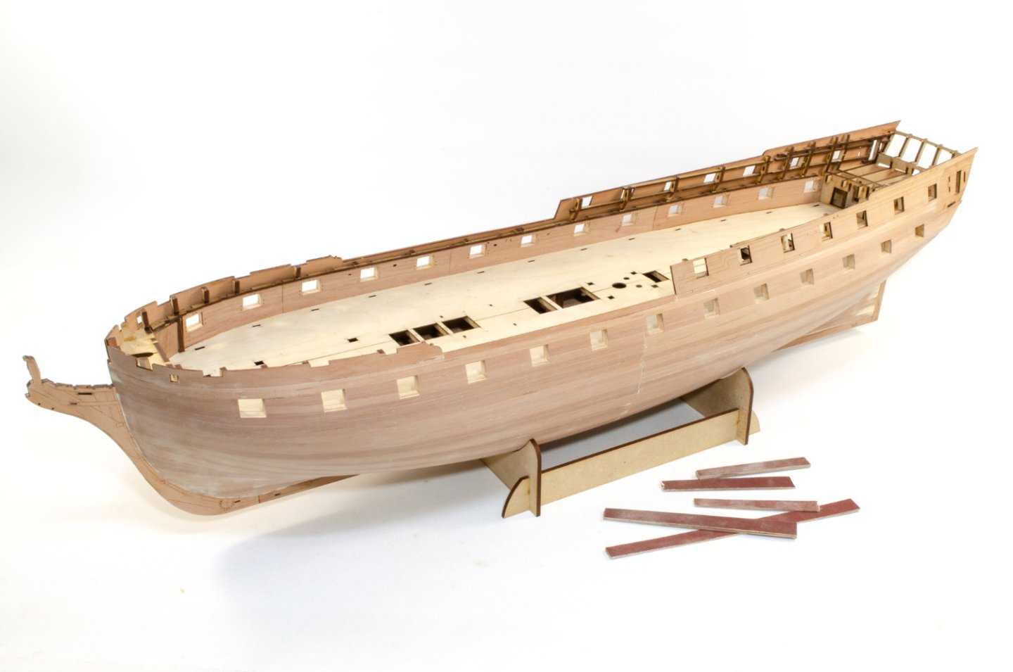
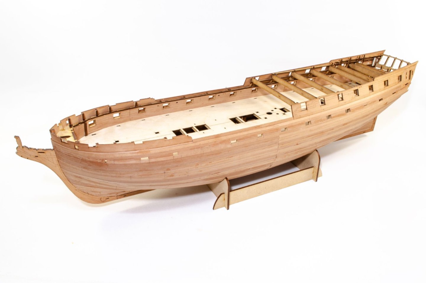
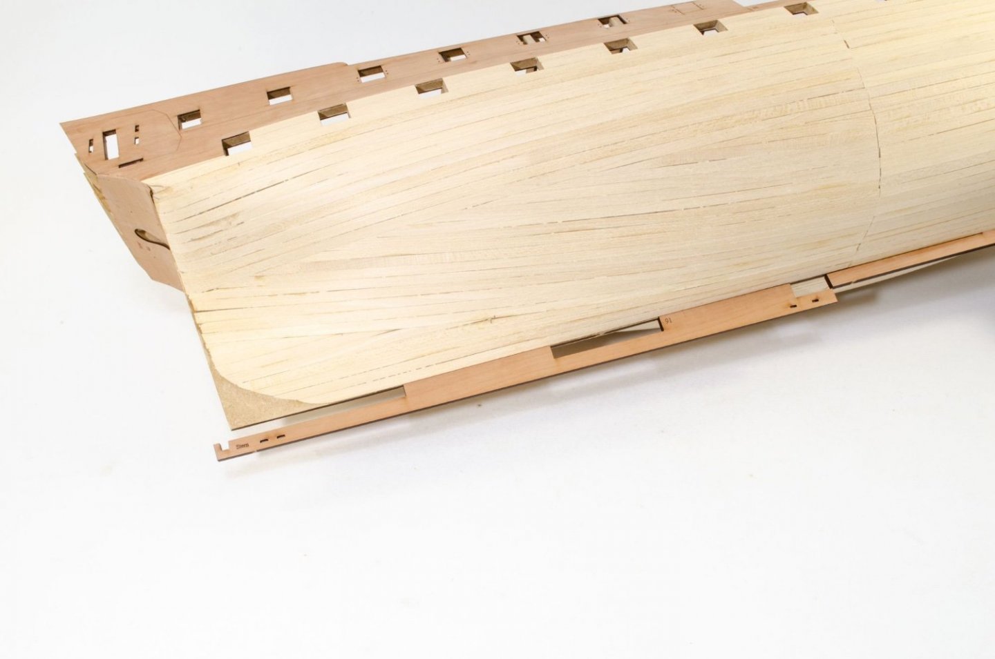
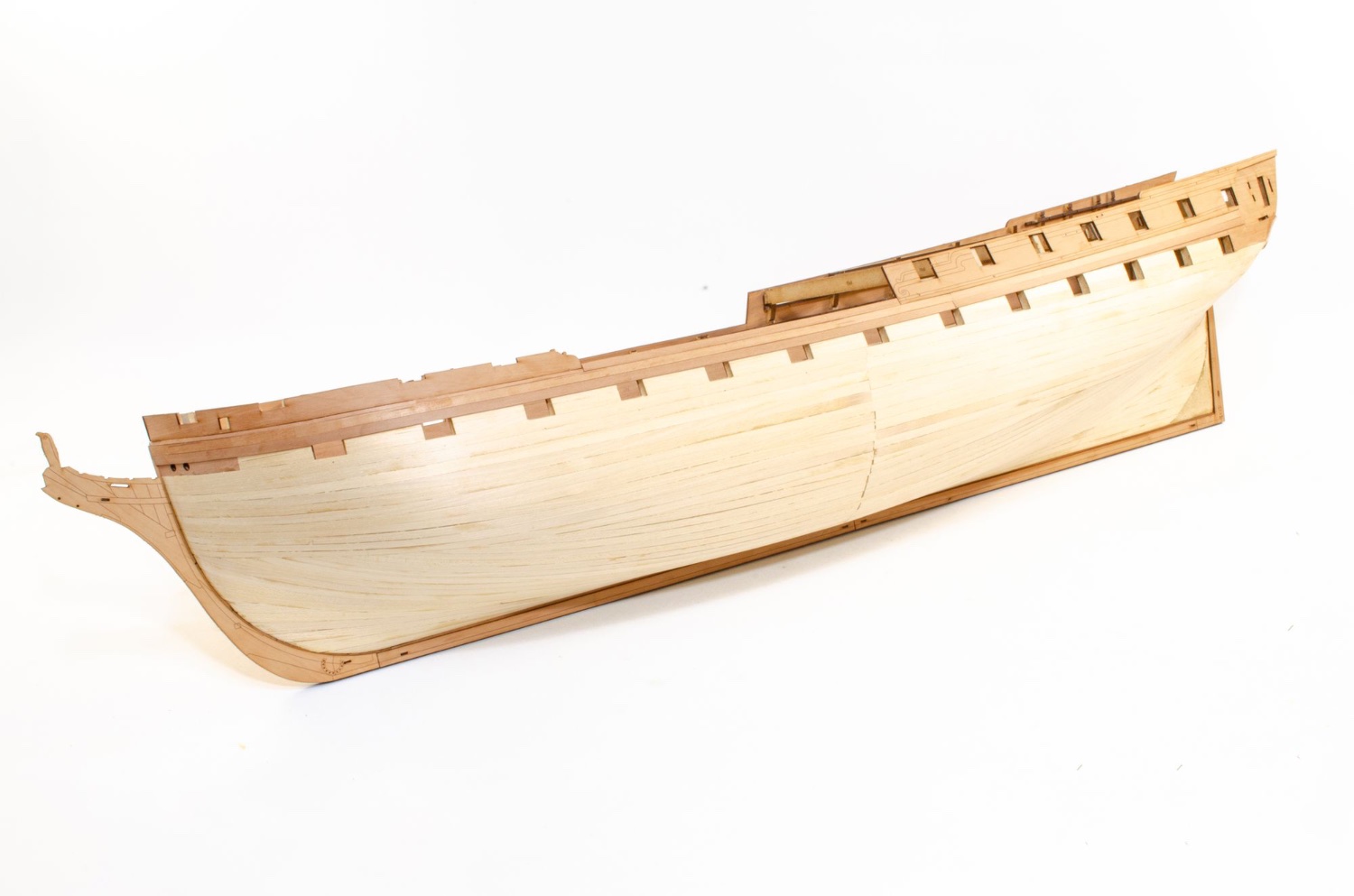
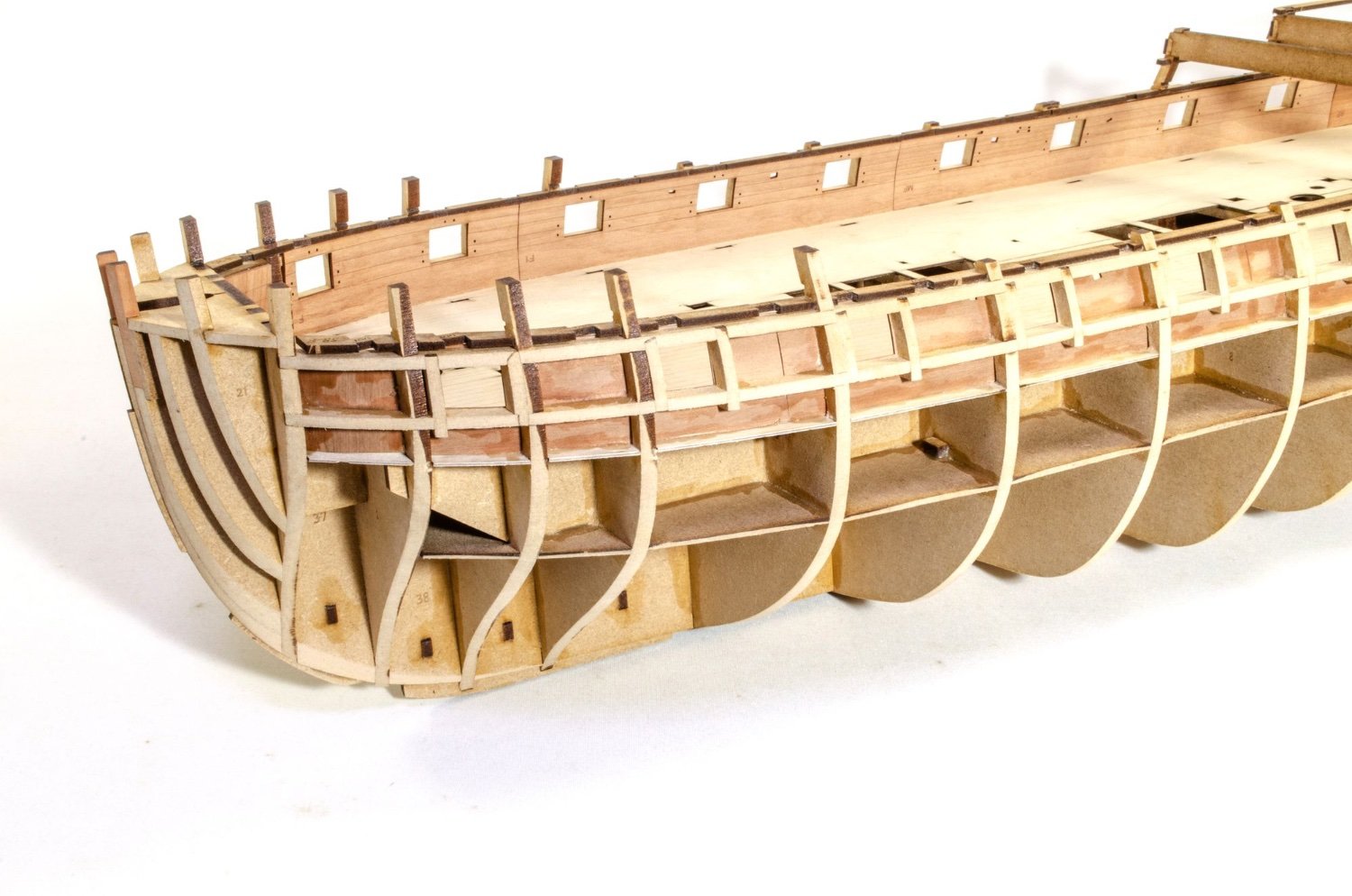
This is only a mini-update as I've been away on holiday. This shows the hull up to completion of second planking, but I have started on sanding this smooth, which will be seen in next update when I've added the wales and done some other stuff.
The plan will give a position below each gun port, where a mark will be added. It's here that a plank will be run, from stem to stern. It also gives a nice reference to the upper wale strake which will lie directly over the top.


The hull is now sheathed in pear. Sanding begins.
-
4
-
-
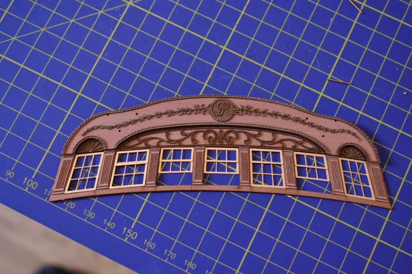
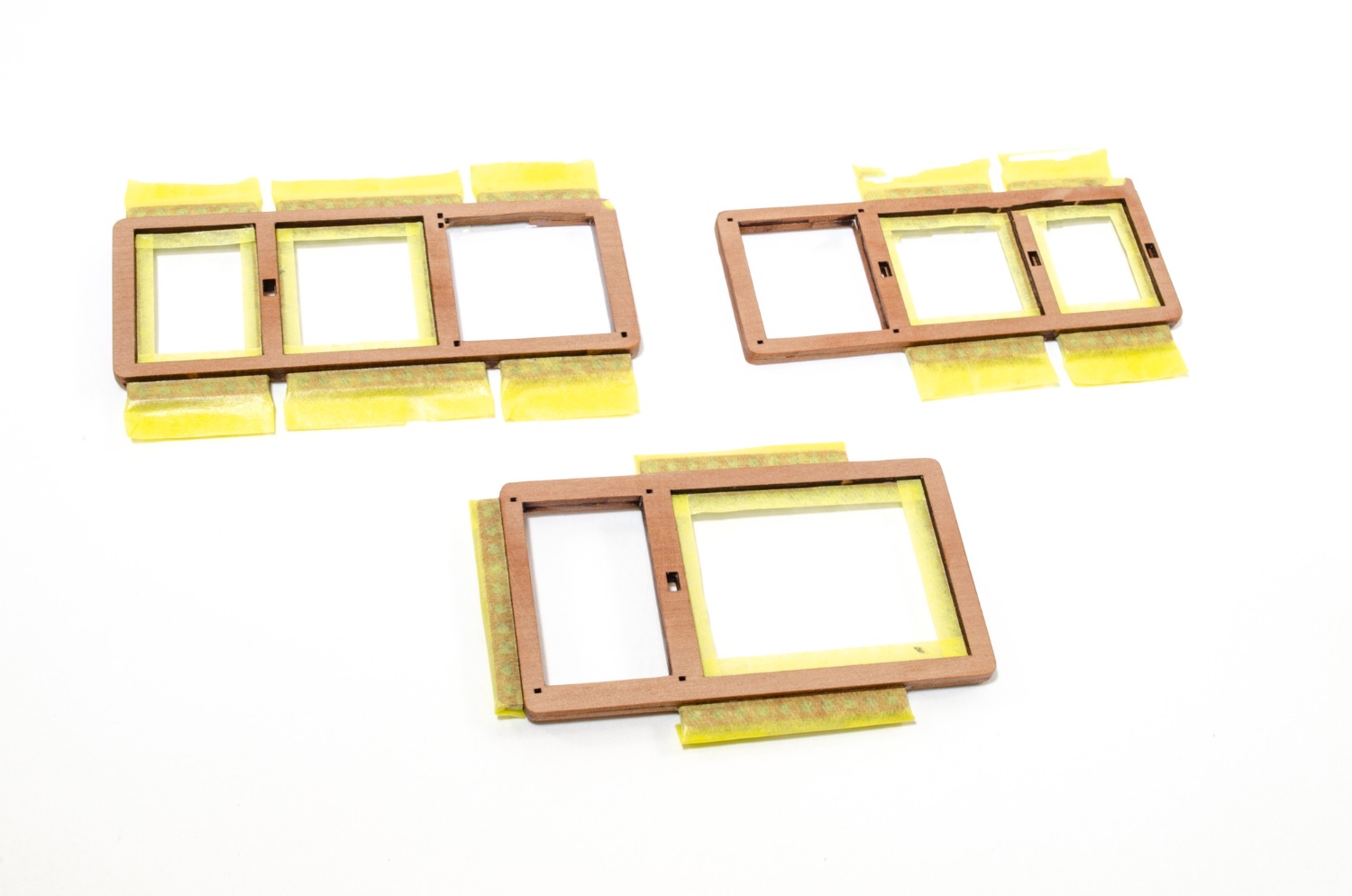
Just checked stern windows - there will be options for open or closed...
-
3
-
-
The rest of the keel is now added, and then the rudder post is fitted with its engraved facings and installed. This part sits into the notch in the keel and pushes tight up against the inner stern construction. No clamping needed!

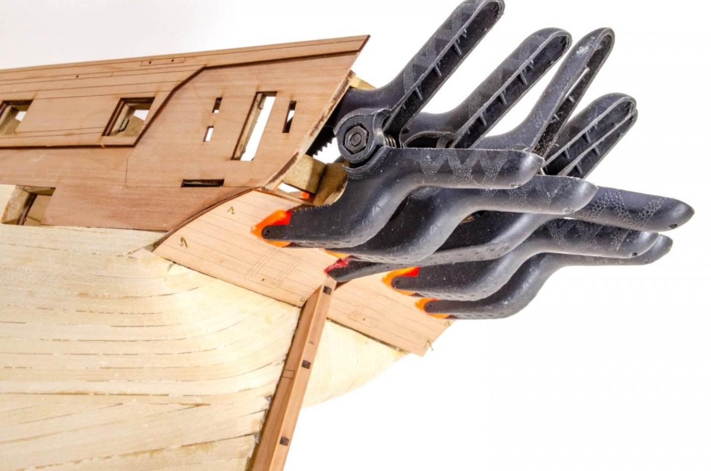
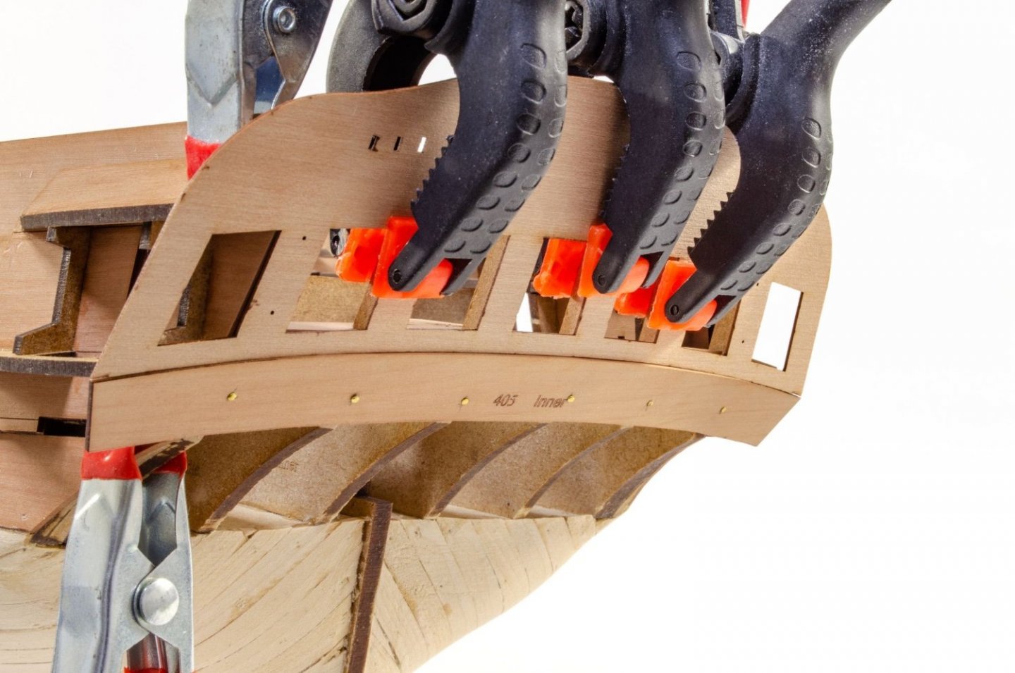
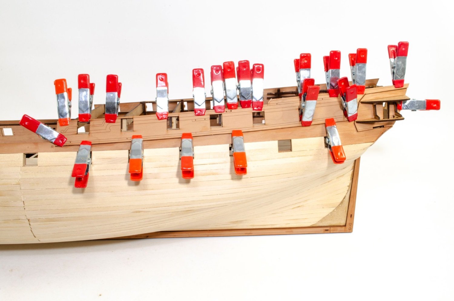
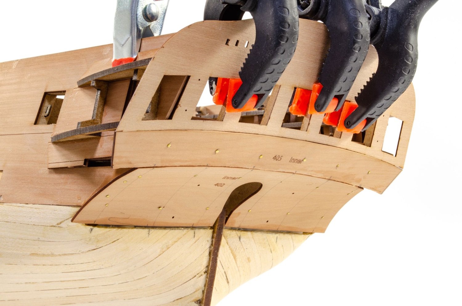
The rest of the keel and prow engraved facings are added and copiously held with clamps. You can never, ever have enough of those.
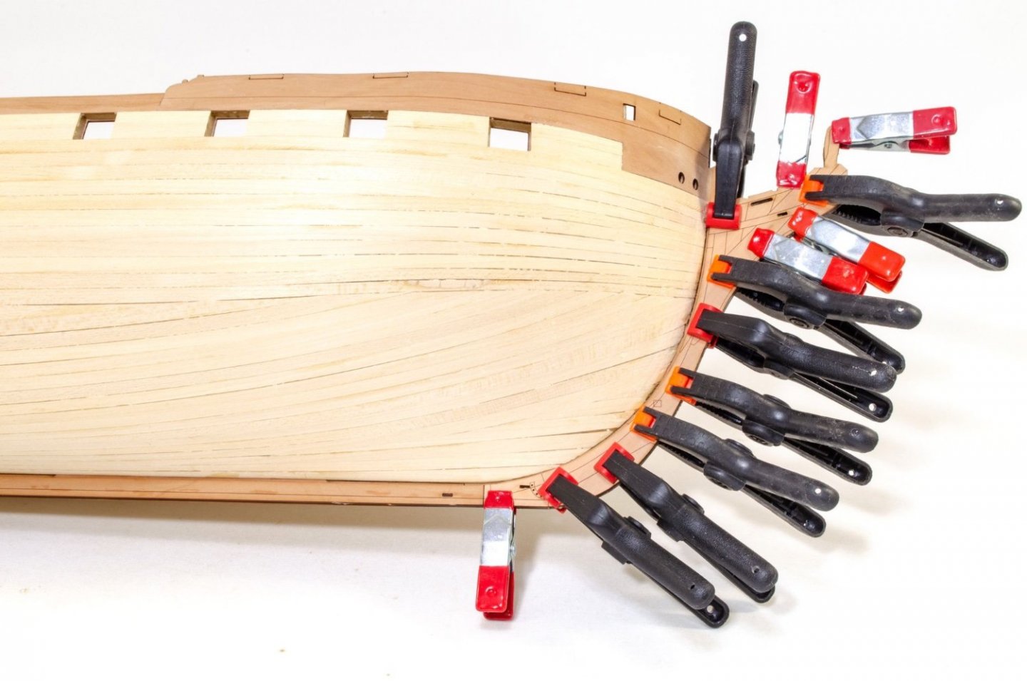
The second layer of timber starts by fitting the outside forecastle bulwarks. When these are dry, the gun port blanks are removed and the hull starts to transform a little.
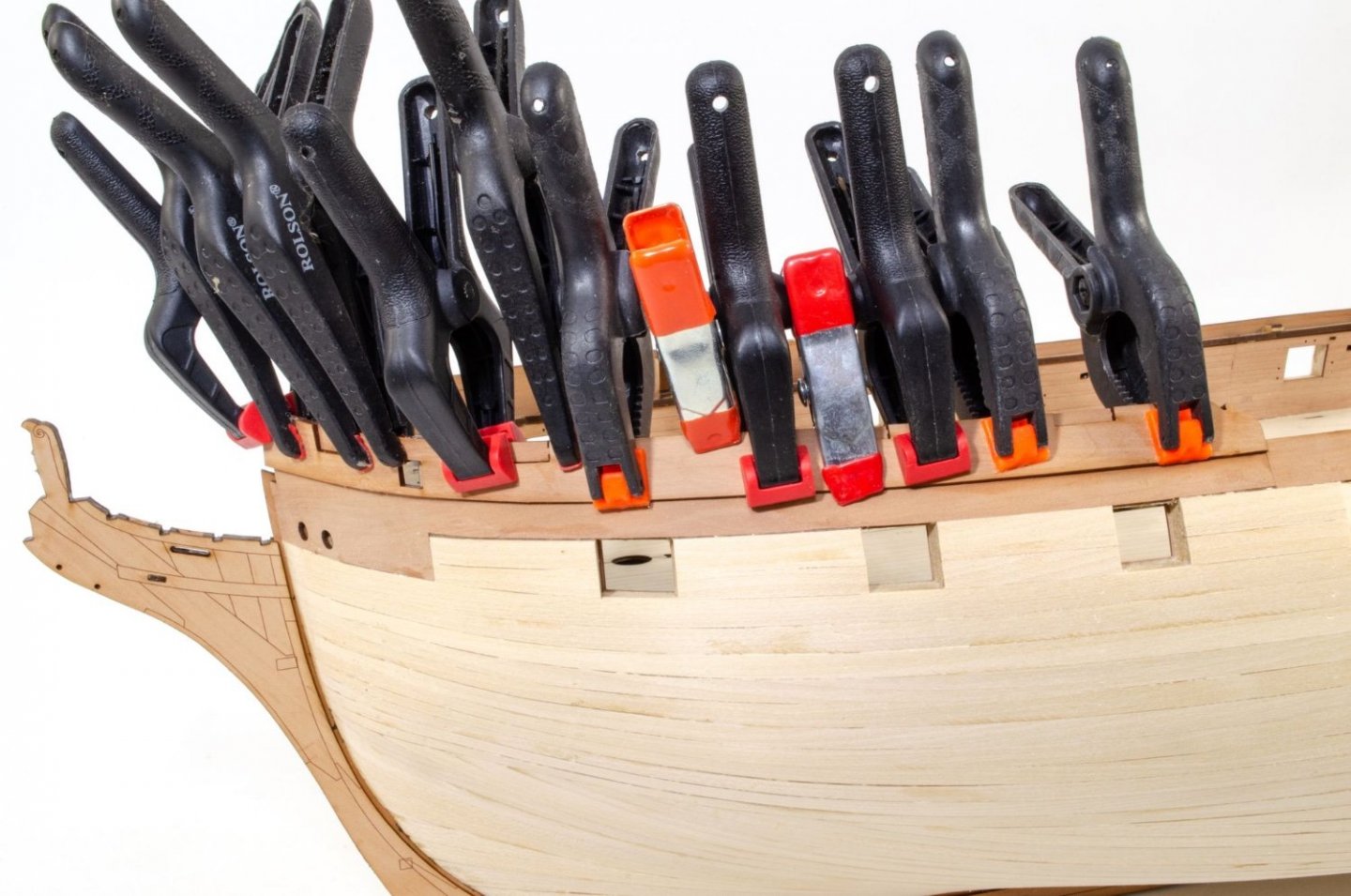
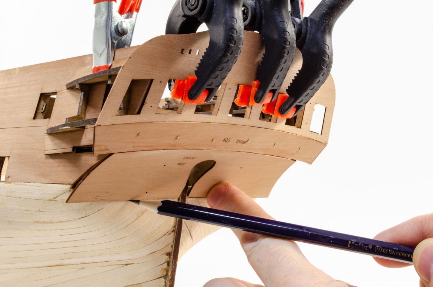
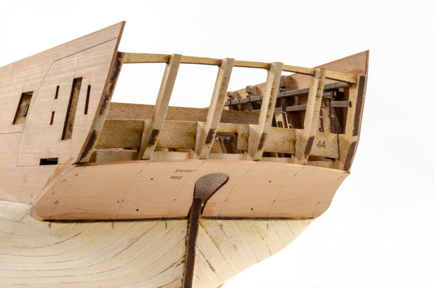
The rear outside bulwarks are now to be fitted. The quarter gallery frames are temporarily clamped into place and the parts glued. Note that I've remove the blank in the fore gun port hole.

The lower, outside counter is now glued, clamped and pinned in place.
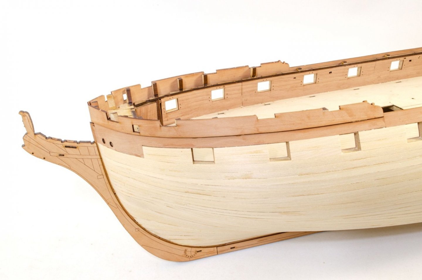
Indy now looks like this. ☺️
Until next time.
-
3
-
-
Let's bring this up to date.
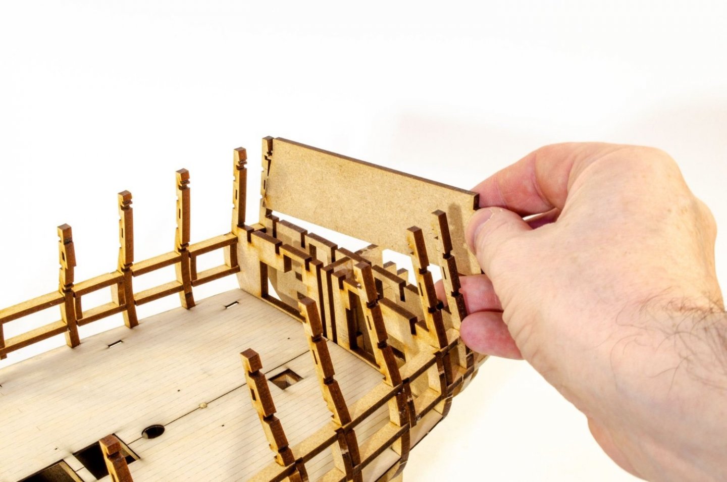
Another element that needs to be temporarily fitted is the shelf that sits in the rear of the day cabin, encompassing the rudder housing.This piece slots into the stern timbers and needs to be pushed the whole way in so the whole protrusion will stick out at the back. That is then sanded flush with the stern.
To make sure the placement of all stern parts is exact so the rails run around the rear and onto the quarter galleries, it' VITAL that we work from the top, downwards. The main, inner stern is first temporarily clamped into place. It pays off to get this in exactly the right position. When it is correct, the stern will be 2mm above the bulwark, and the inside edge of the outer window will sit flush with the quarter gallery frames that are also clamped into place. The bottom MDF quarter gallery frame will also angle in line with the bottom of the stern. Lastly, the shelf we fitted just earlier, should sit slightly below the height of the lower window frame. It's a lot to adjust, but trust me, this is the best way of doing it.

The middle counter is now positioned directly underneath this. Some bevelling is done to make sure it fits snug against the upper stern. The bottom edge of this part will sit at the point where the stern flows into the lower curve. If it doesn't, this part can be trimmed slightly. Pins are now used to hold this in place. Again, NO GLUE!
The bottom stern counter can now be fitted. This was first soaked and allowed to dry around a tin so that it had a gentle curve that would take the strain off the next task. The counter is pushed up directly underneath the middle counter and the bottom edge of this part is marked with a pencil. My prototype varies very slightly to the production kit, and that will be reflected in text in manual. I now cut along the pencil line and remove the planking from above that line.

The lower counter is now glued and pinned and into place.

The upper parts are now removed as adding them at this stage will mean they'll get snagged. The lower counter is now shaped into the hull.
The prow underwent its third revision to cater to the figurehead, and this new part was now glued into place on the hull.
Next, the lower keel parts are added...
-
3
-
-
Not a massive update, and there have been two prow reworks to get it spot on.
That held me up a few days in total, plus my health hasn't been conducive to extended workshop sessions. Anyway, the hull is now fully first planked in 6mm wide strips of 1.5mm thick lime. For me, that's the king of my least favourite parts done, next to sanding it! I used a combination of palm sander and manual muscle/sweat to clean up the planks. After that was done, I opened up the gun ports so they are almost at right size.

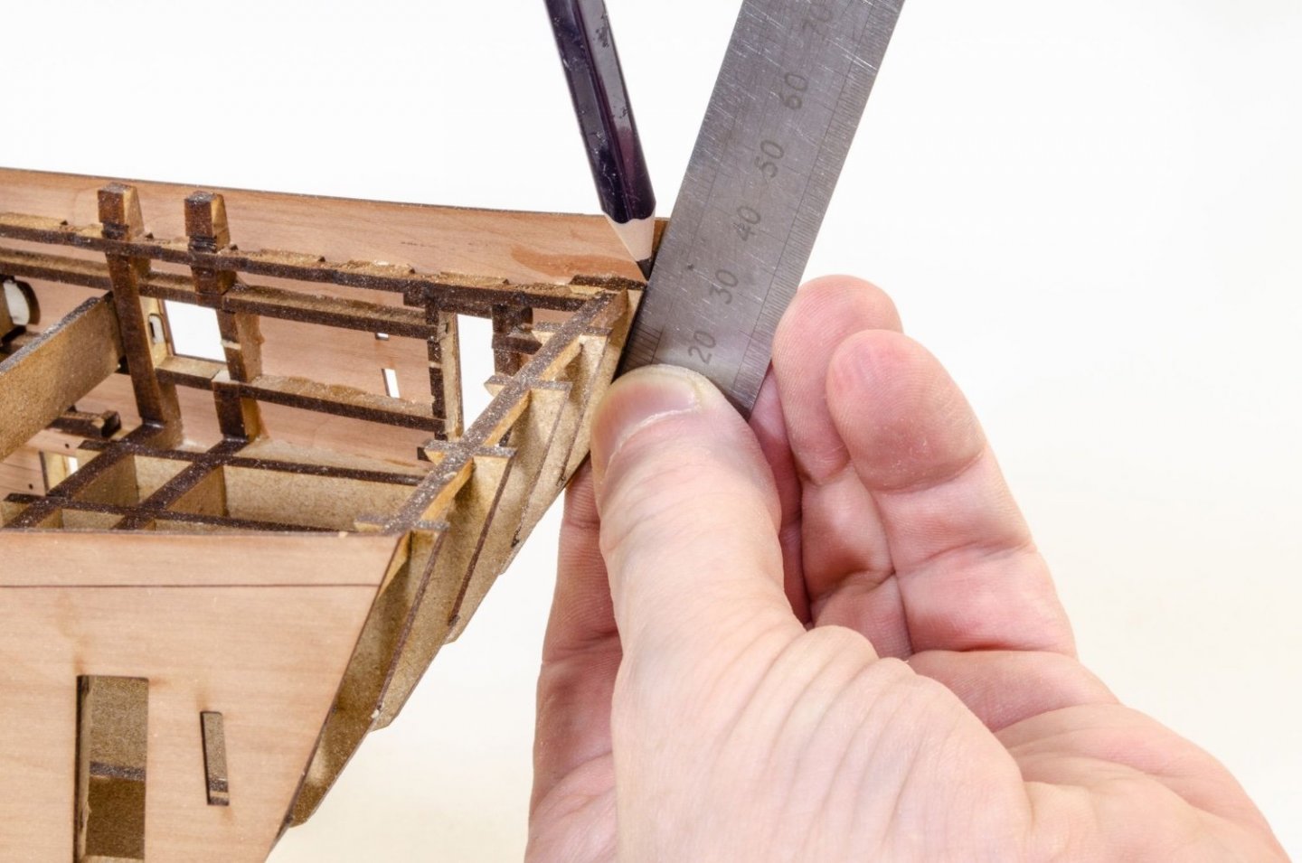
The inner, side bulwarks are left a little long so they can be trimmed exactly to your own build. To level up to the stern timbers, I use a rule and pencil to drawn an extended line from the stern timbers, then trim/sand to the correct length. The lower, curved area etc. are also trimmed back to the stern timbers.

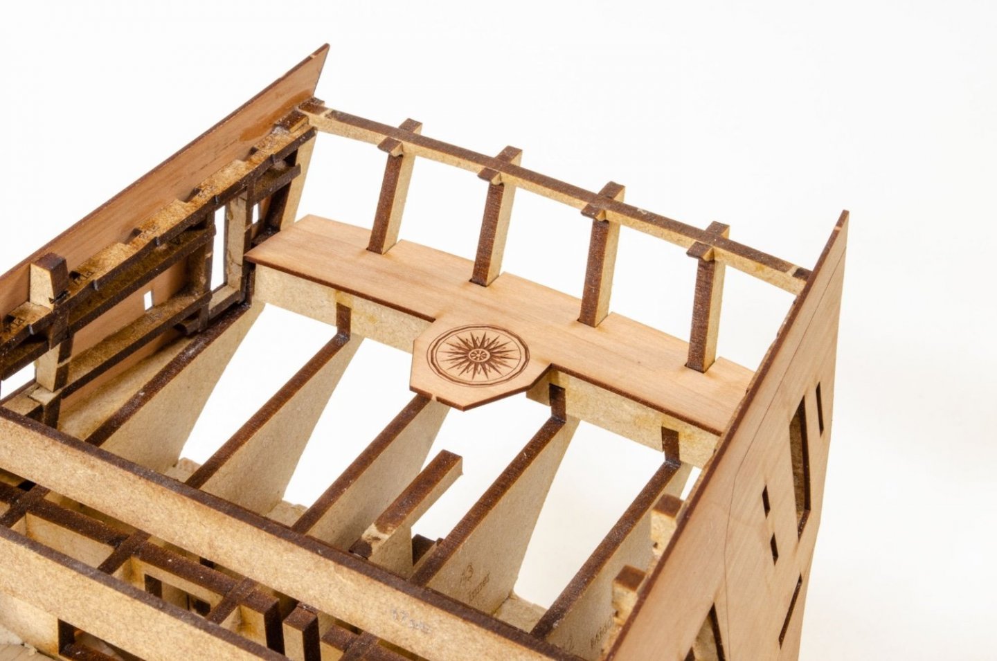
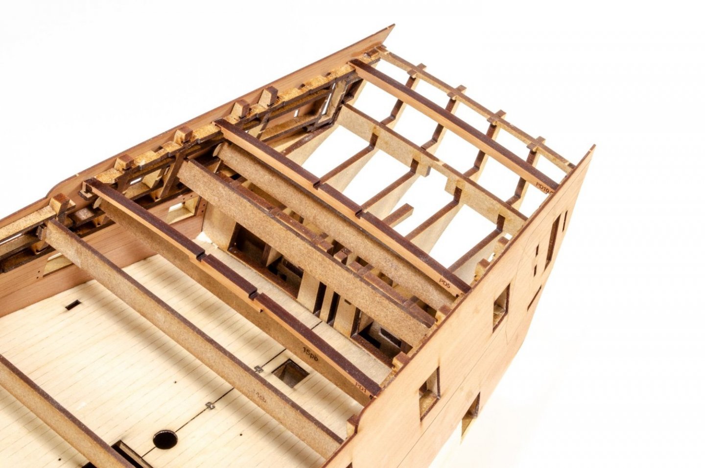
This little part sits across the inside of the stern timbers. It will later have a shelf sat on top which will help with its placement. Here it is fitted.

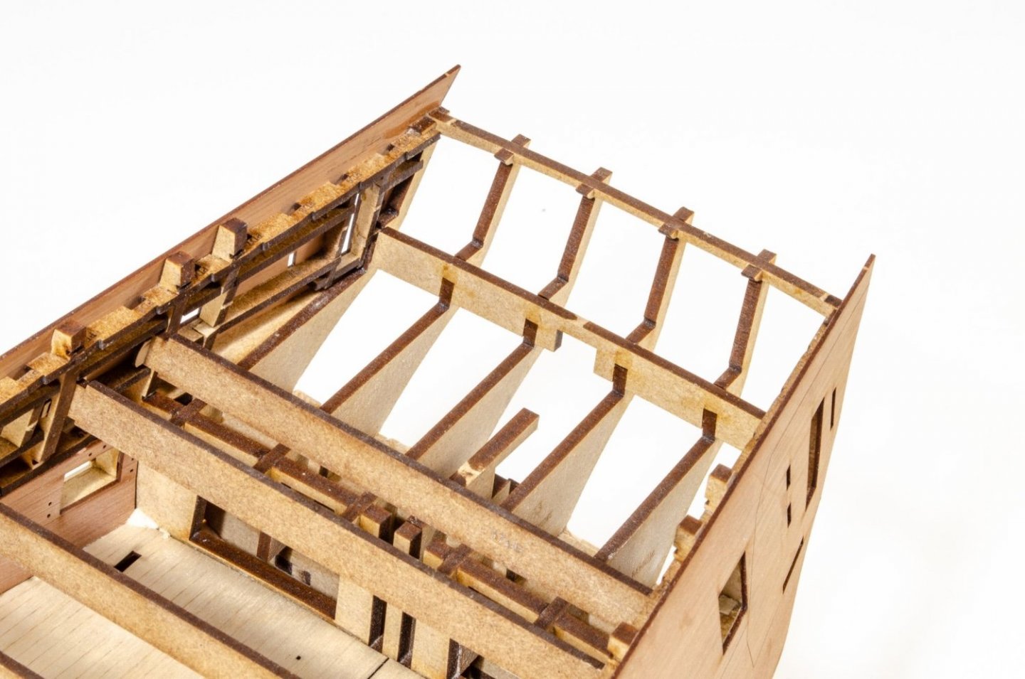
To make things easier later on in the project, three poop deck beams are slotted into place (#1, 5, and 10) so I can temporarily fit the poop deck. This will help you sand the back edge to the same as the stern. Even though I show/include this, on my prototype it fit without needing any sanding at rear.

The quarter gallery frames are now built up...well partially. These will soon be temporarily fitted to help with the vital positioning of the stern elements (stern face, middle and lower counters).

Until next time...
-
6
-
-
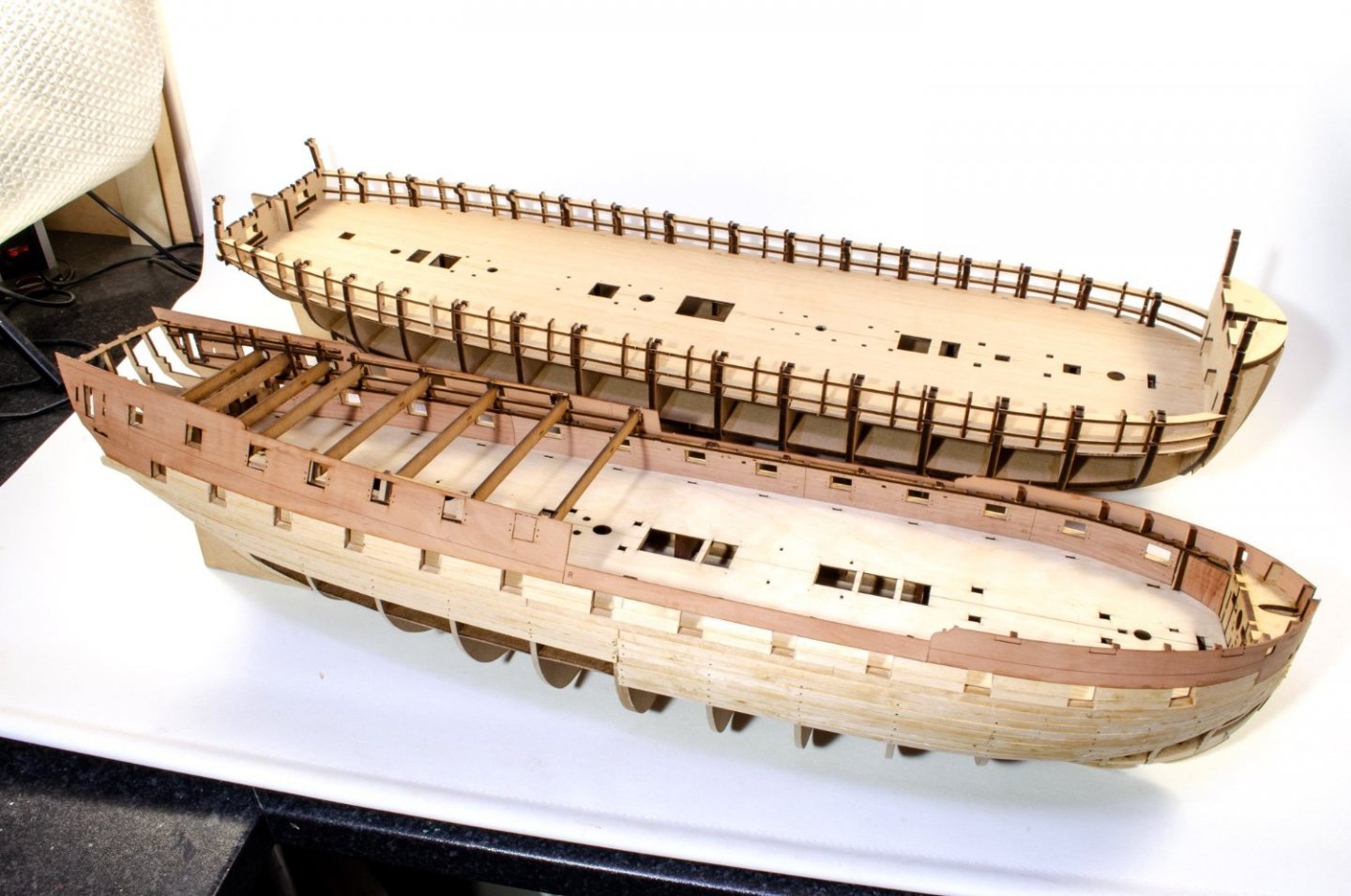
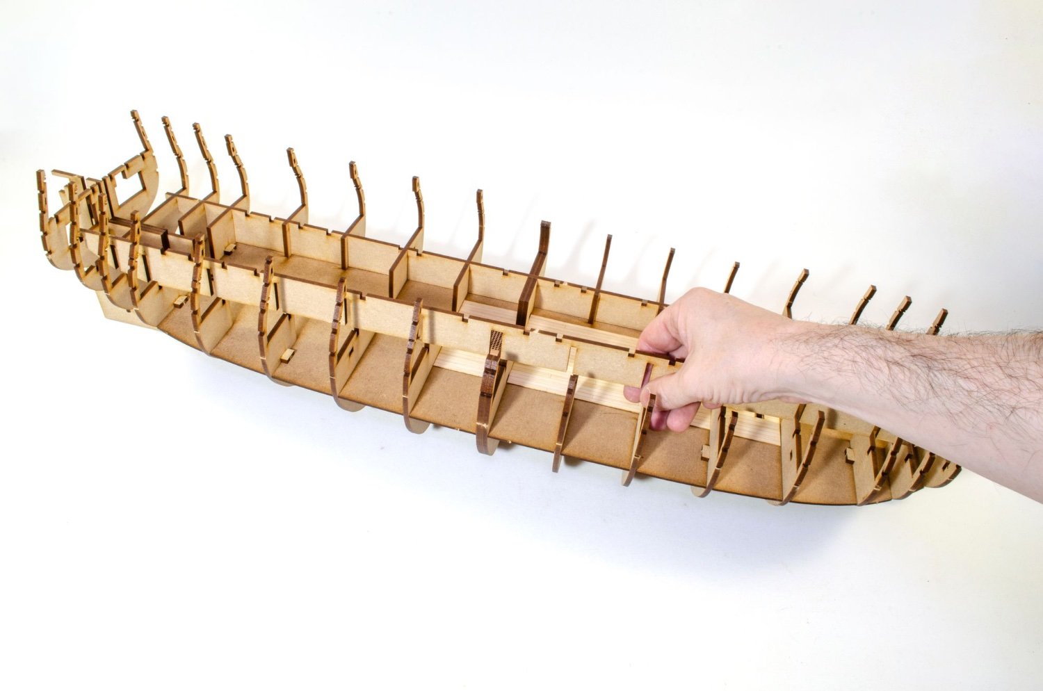
Not great photos, but I have been asked several times about the size of Indy compared to Amati's 1:64 Victory prototype, so here's a couple of photos for you.
Remember that the angle of the first pic makes Indy look bigger than Vic. It isn't! That's why I did a photo of Indy sat on Vic's lower gun deck.

-
3
-
-
Just for some info, Indy will be approx 880mm tall.
Ok, onto business.
The hull is now faired. This isn't really a task you can sit there with a piece of sandpaper and hope to achieve inner calm. Chris finally talked me into getting a palm sander (mouse), so I splashed out on a Black & Decker one. Even with this, fitted with an 80 grit pad, this job still took me a total of about 5 hours, along with the final task of wrapping some sandpaper around a 12 inch piece of thin ply to absolutely ensure the curves were right....plus the joyous task of blending those last bulkheads and fairing blocks into the keel.

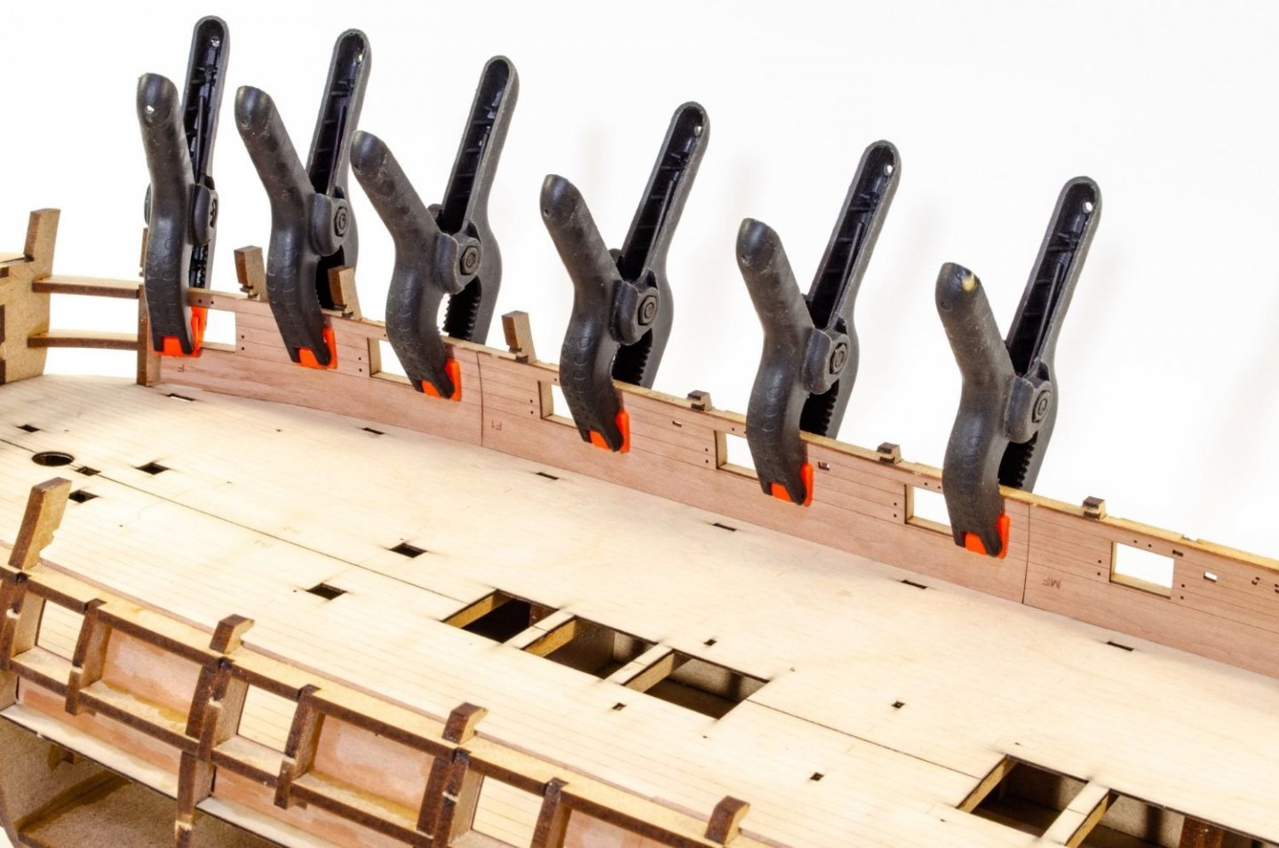
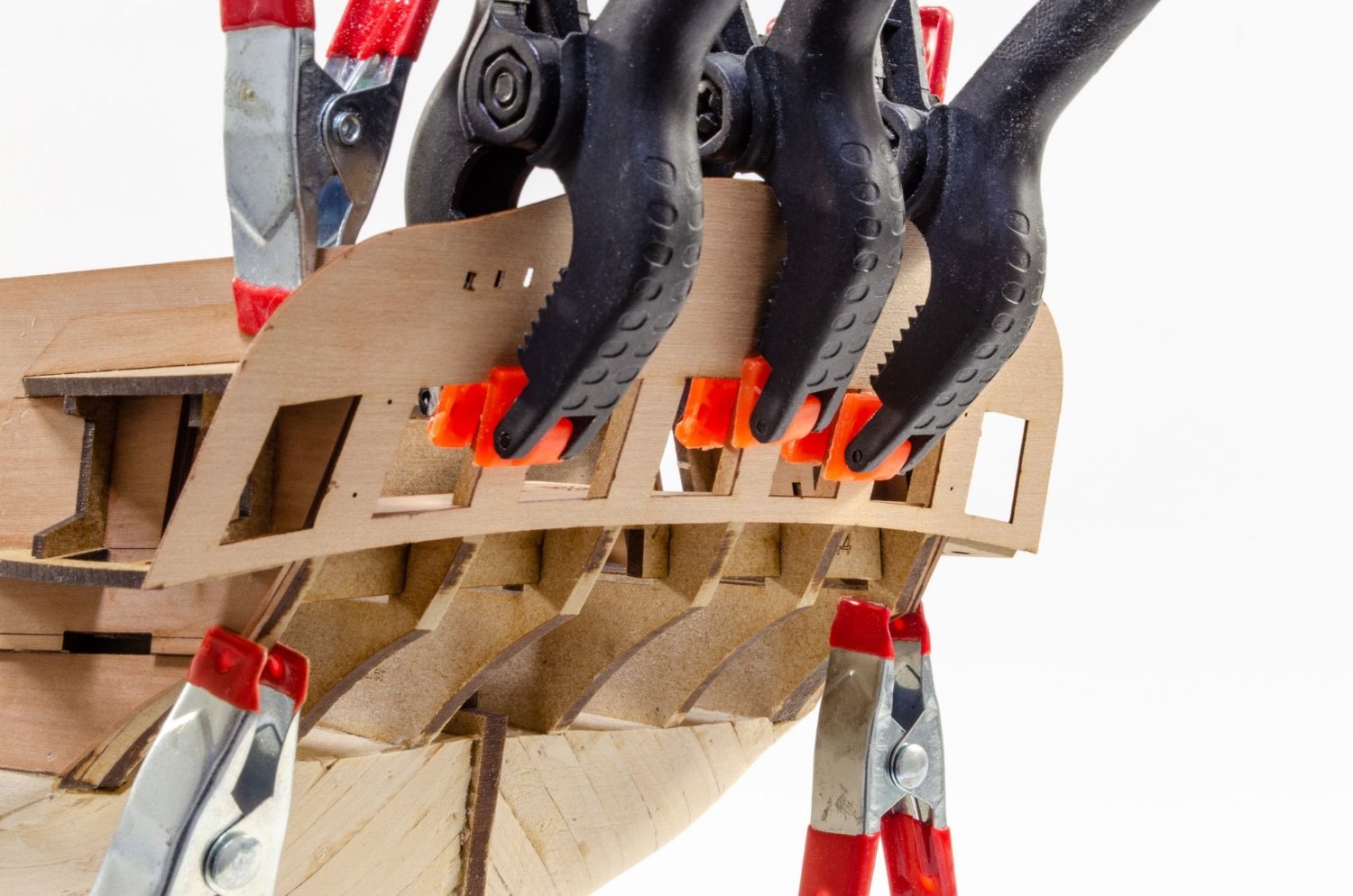
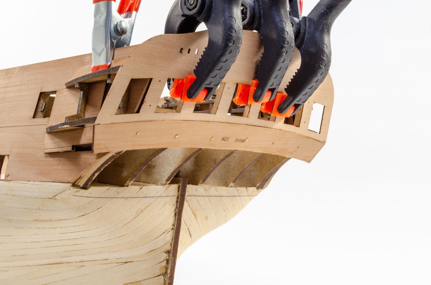
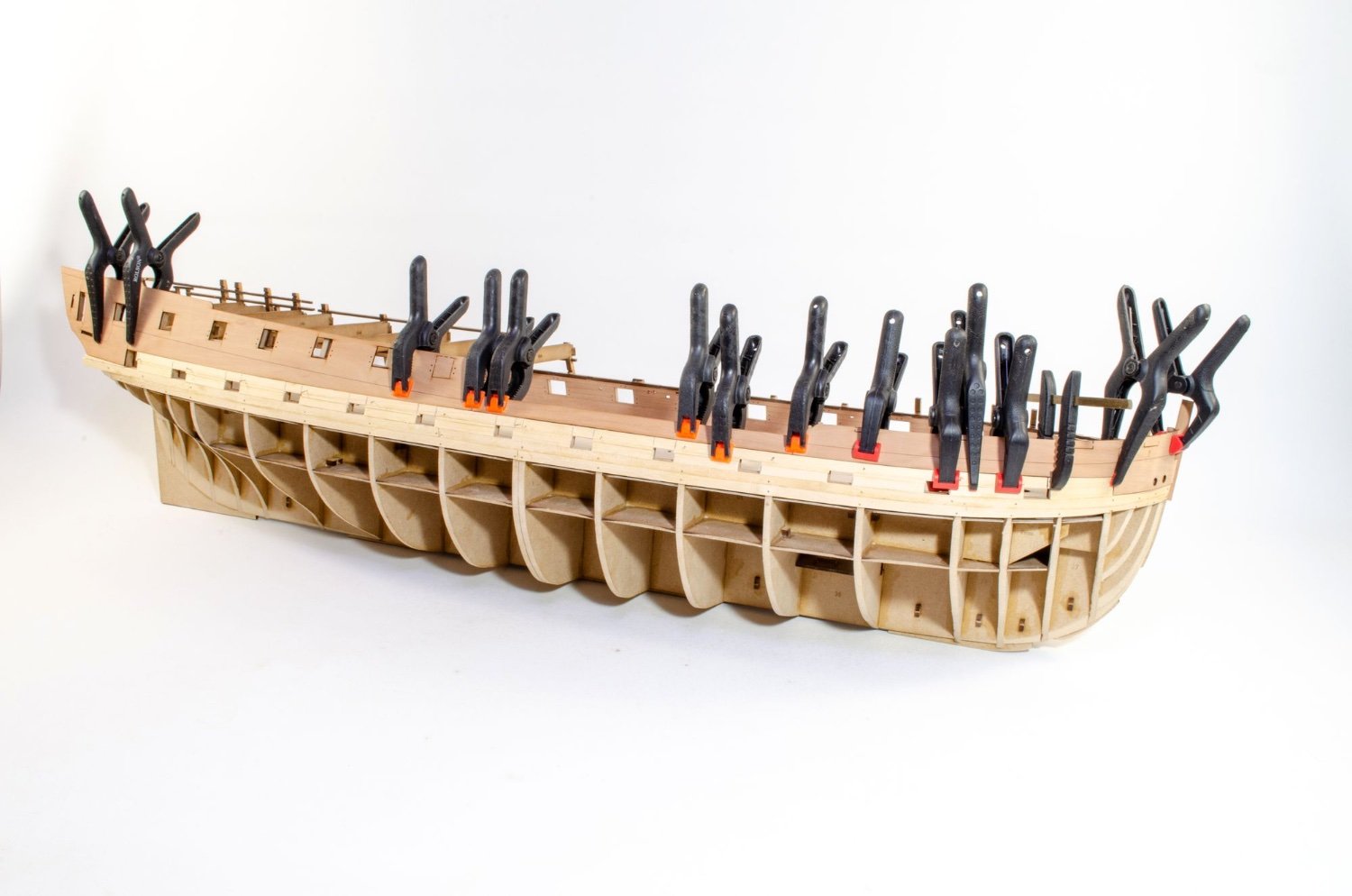
There is a lot of regular planking on Indy, but the inner core of the outer bulwarks are laser cut. So as not to stress out the forward bulwarks and those temporary gun port sections, these were first soaked and clamped in place. These were left for a full 24hrs to dry out and shrink back to their normal size. Pear has a hell of an expansion, even when soaked for 30 mins in hot water, so you really need to find a book to read, guitar to play, or TV to watch while this dries.

Now that the parts are completely dry, I draw around the forward position of the bulwark so that I have my positions for the flow of the first plank that runs below the gun ports, and also the extent of the planks above this. It's important to know here that this pear part sits along the top of the gun ports on the main deck.

The pear bulwark is now removed and the first 1.5mm thick lime strip laid along the bottom edge of the gun port sills, and along the lower line I've just drawn. On the prototype, each plank is 500mm long, and they meet up on the double thickness bulkhead #9. We're not yet sure if that will be the case on the final product.
The back end of the same plank run is now installed. These planks are pinned until dry. If you pin all the way through, they will penetrate through the inner bulwarks, but that doesn't matter as any holes will be in the area covered by the spirketting.
The pear bulwark sections are now temporarily clamped into position so the bottom edge runs along the top edge of the gun ports. You don't need top do this but I just considered that it was good insurance that the plank that runs directly underneath these pear parts, would be properly installed and a snug for in that area.It also gives you something to finally sit these parts onto later so you have a much better chance of both sides being exactly equal. Care is taken not to get any glue on those pear bulwarks. The spaces between the gun ports are now filled up with lime strip. This doesn't need to be neat at this stage. They'll be cleaned up later.

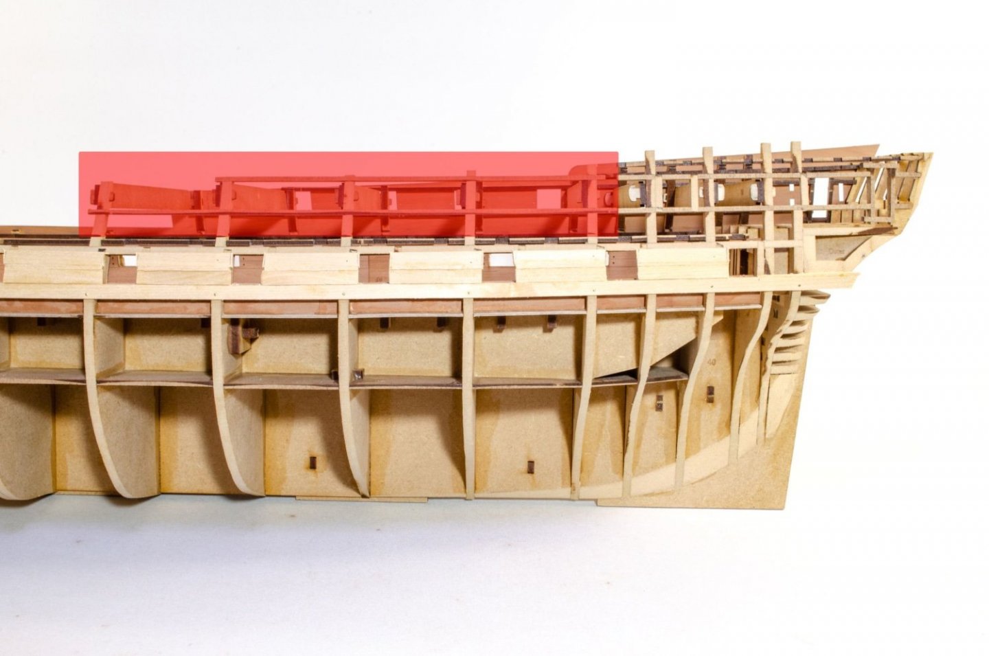
A razor saw is now used to cut away the lime strip in the top row, that is partially obscuring the gun ports.
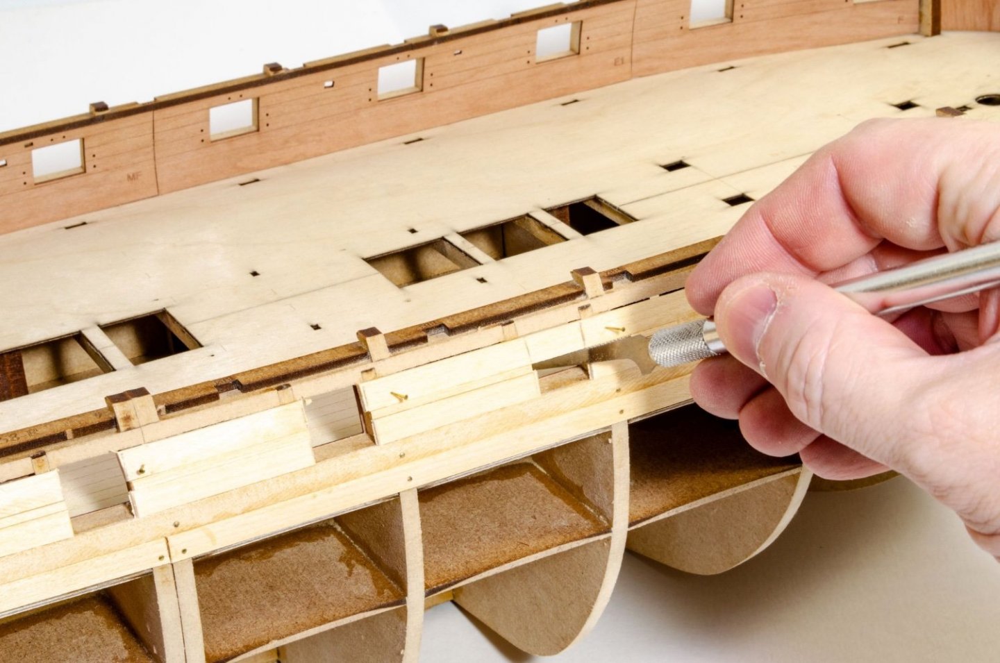
The pear bulwarks can now be reinstated, but before this happens, you need to know a little bit about the side framing of the rear half of Indy. Not all of it will become a part of your finished project. When it comes to gluing the rear sections on first, the area in red here WILL NOT have any glue applied to it as that section will later be cut away. You can see the area with glue covers the the lower area just underneath the red area and for the rear section, it terminates at the point where the longitudinal strips were installed in sections. When you look at the model and my previous photos (without red marks), you can see that split in the strips, denoting the two areas.
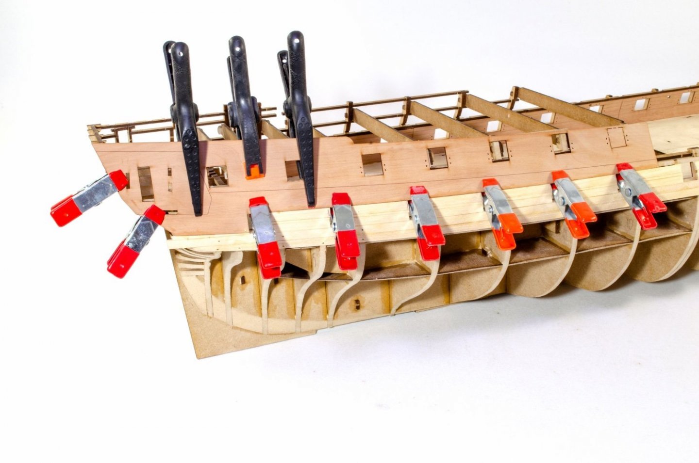
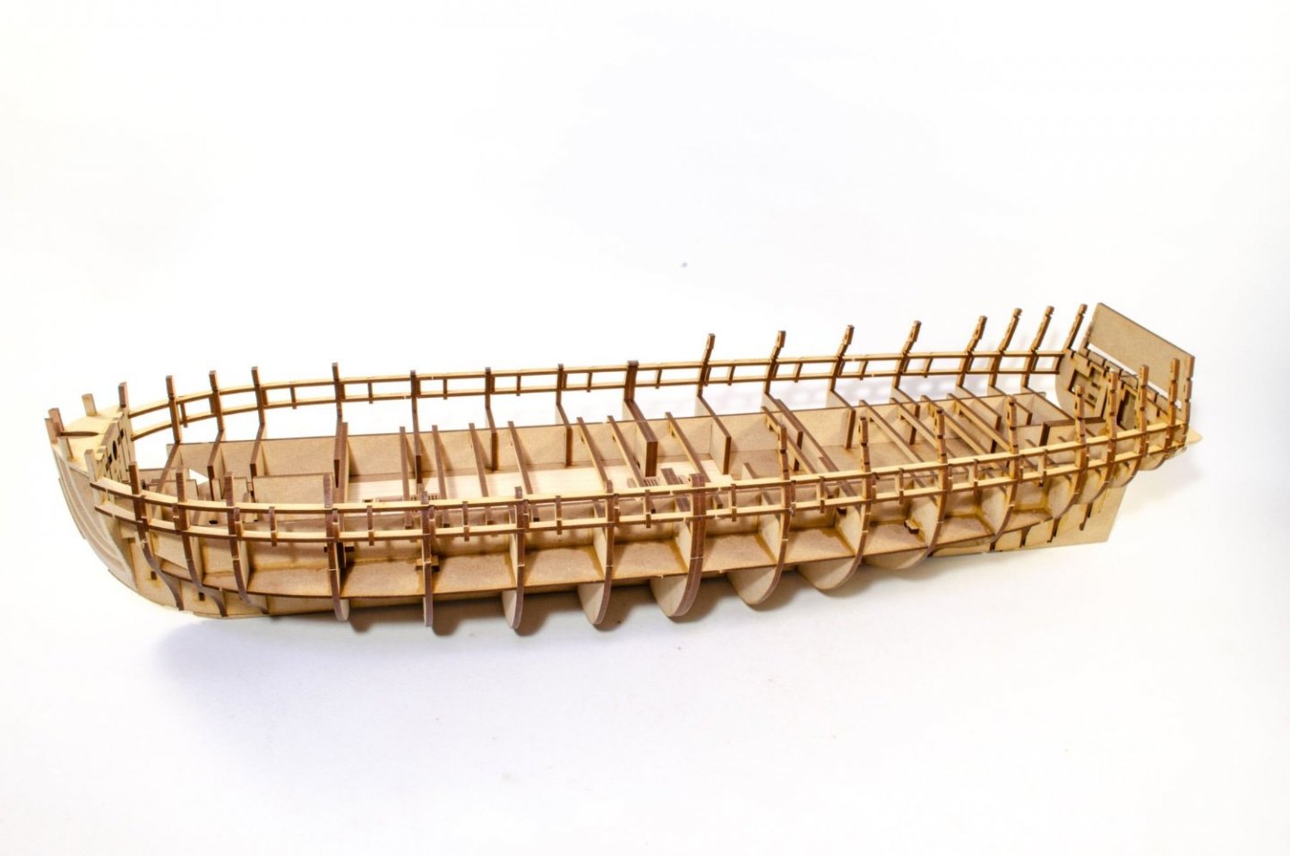
The rear bulwarks are now finally glued into position after some final measuring, ensuring both sides are in exactly the same position. This isn't too difficult now that this part sits upon that lime plank. Other factors also help too, such as the two rear gunport frames on the quarterdeck and the quarter gallery doorway. Just check at the back end to make sure things align with the stern timbers. Of course, you don't need to worry about gun port alignment on the rest of the quarterdeck gun ports as those frames will later be removed, as discussed. 2 inch clamps are very useful here to make sure the bulwark is squeezed into the hull curvature, as they can hook through the gun ports.
The mid and fore pear bulkheads are now glued into place.

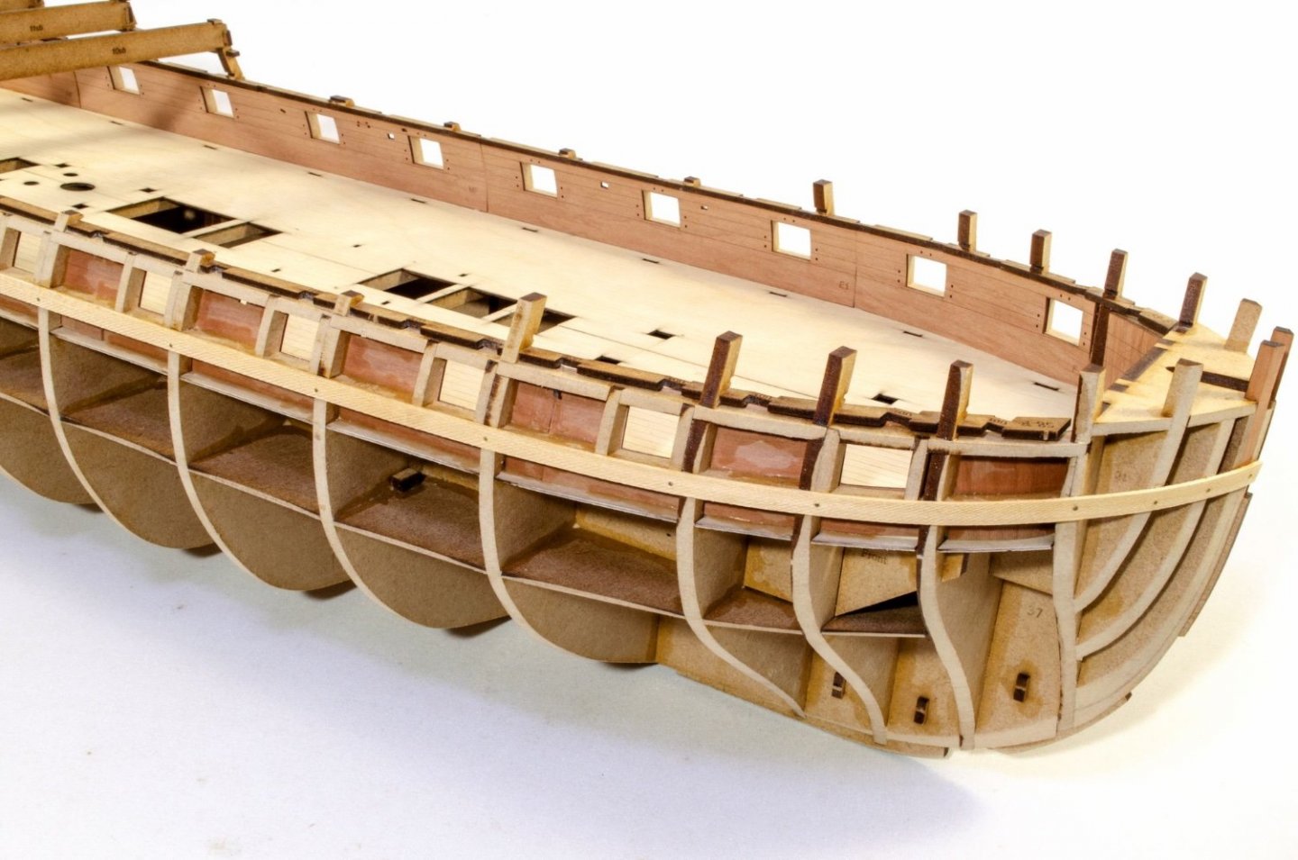
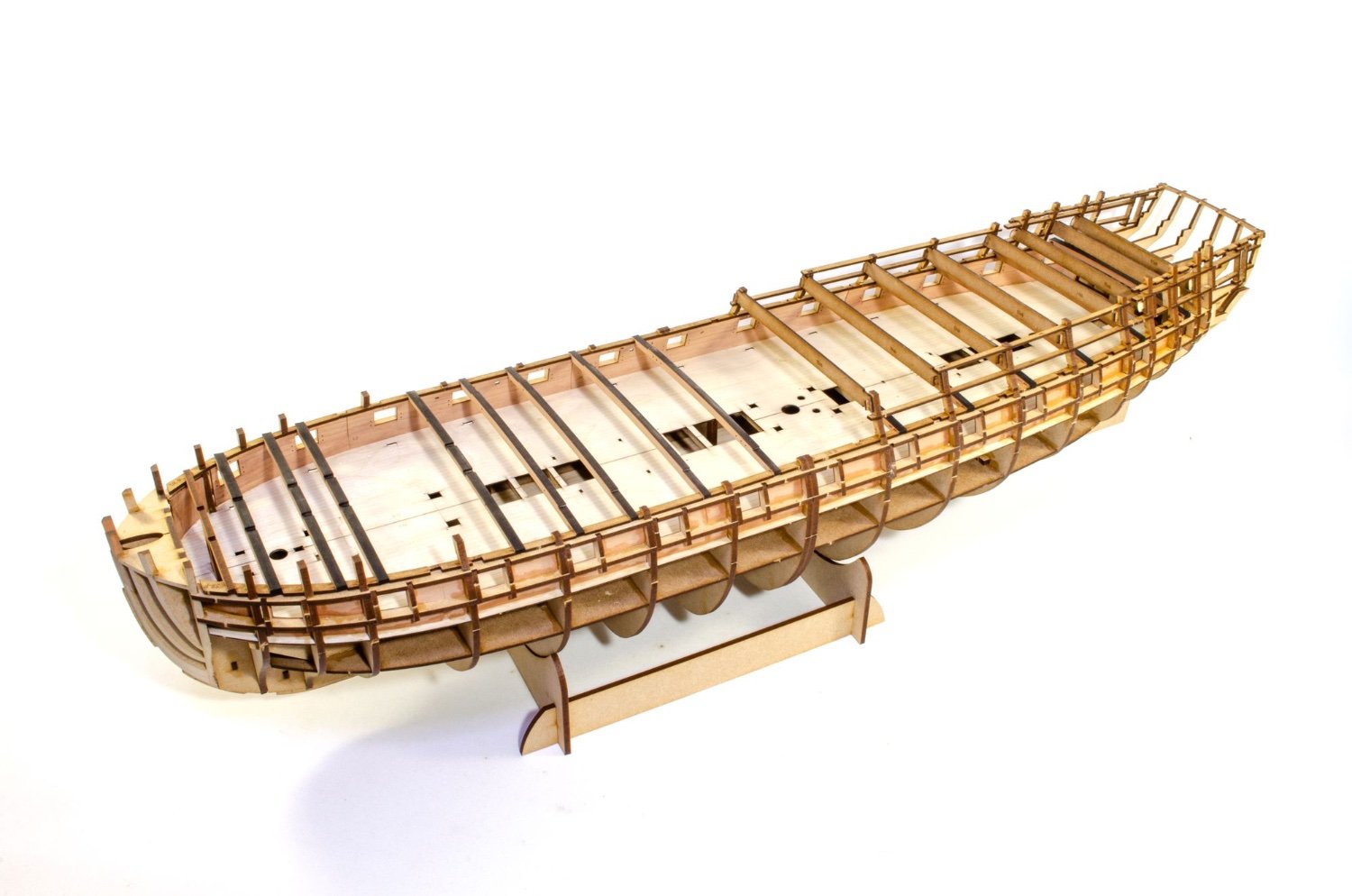
And for the last part of this update, here's how she currently looks. Next job is to cover that lower real estate in lime planks. Remember, this is the same size as Agamemnon!
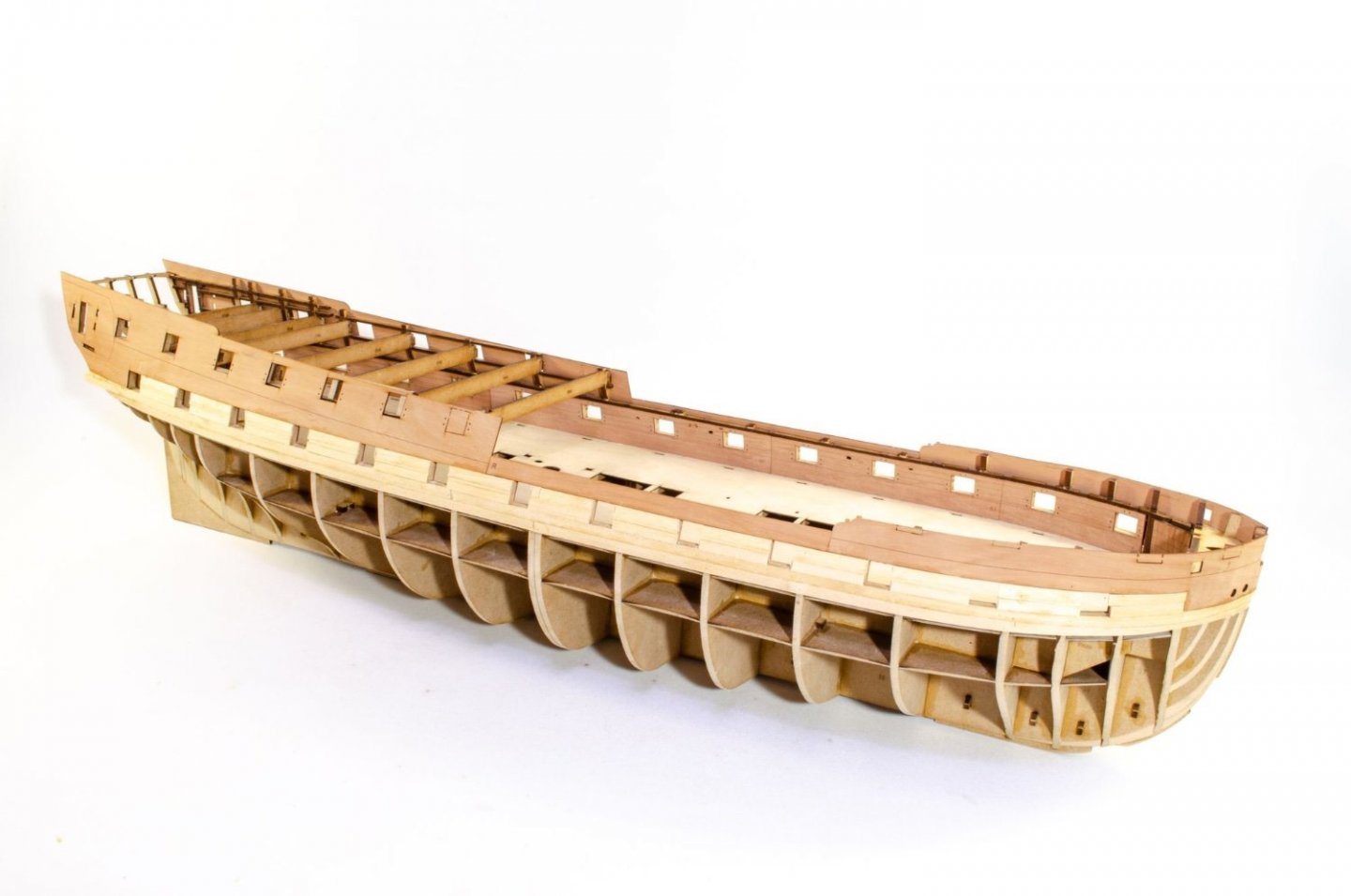
Until next time....
-
4
-
-
Another update.
Not too much to show this time, but there was a lot of work in terms of sanding and waiting for soaked parts to dry before gluing etc.
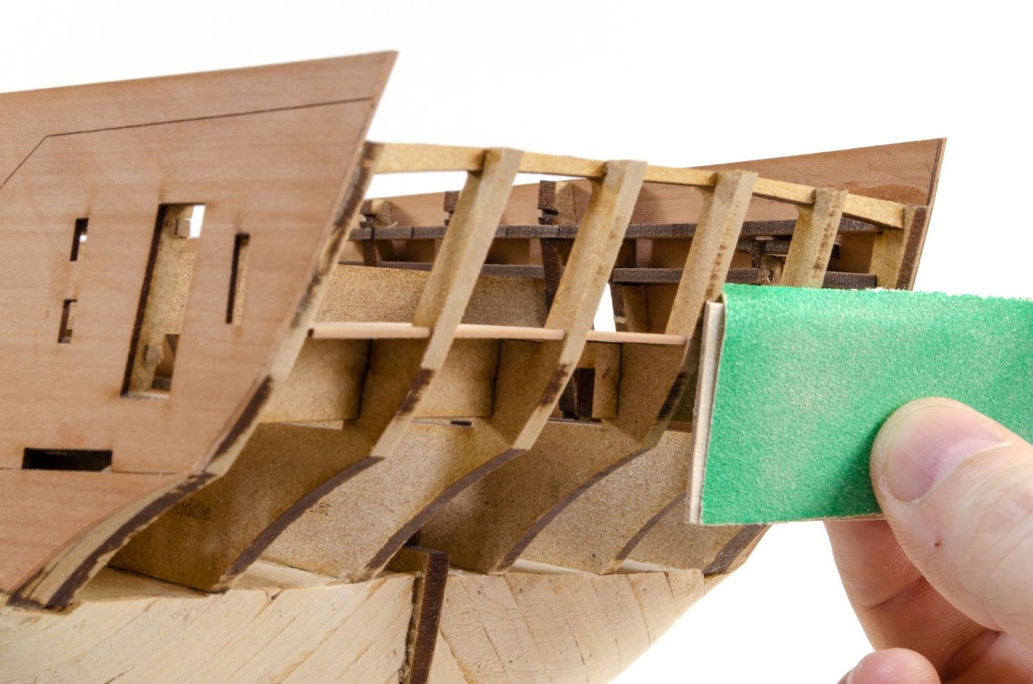
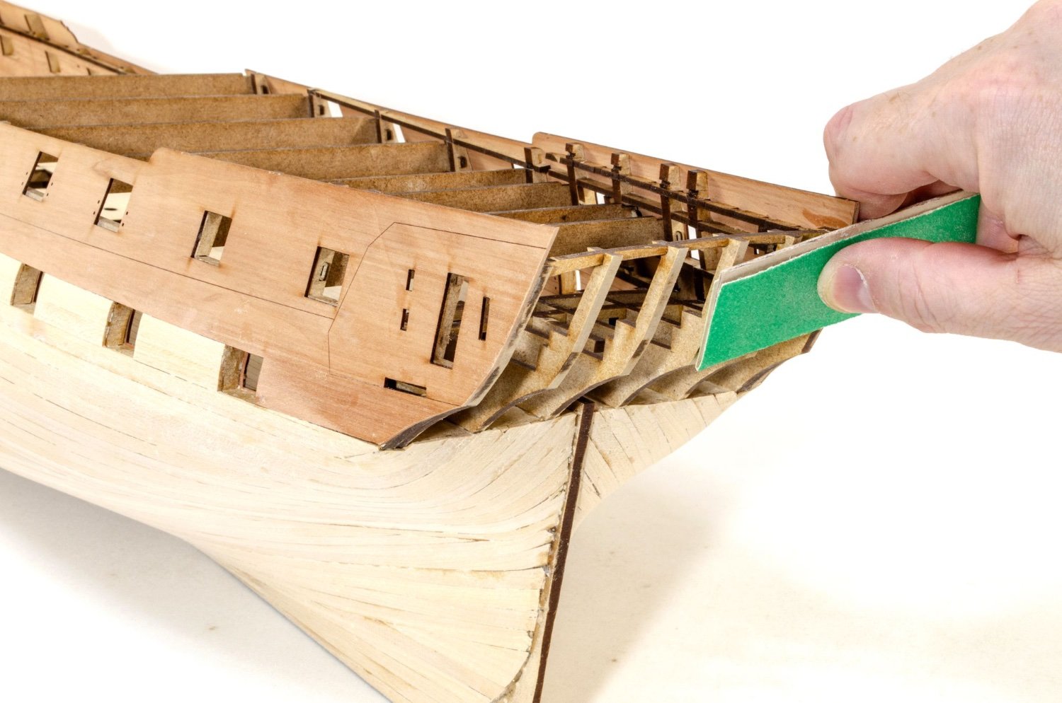
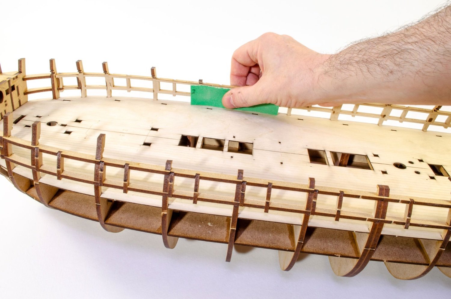
Before I could proceed, I needed to sand the inner bulwarks. This isn't too bad of a job...just time consuming. Despite my pic, you're best rolling the hull onto its side on a towel, and applying pressure downwards when sanding. This is done until everything is nice and even.
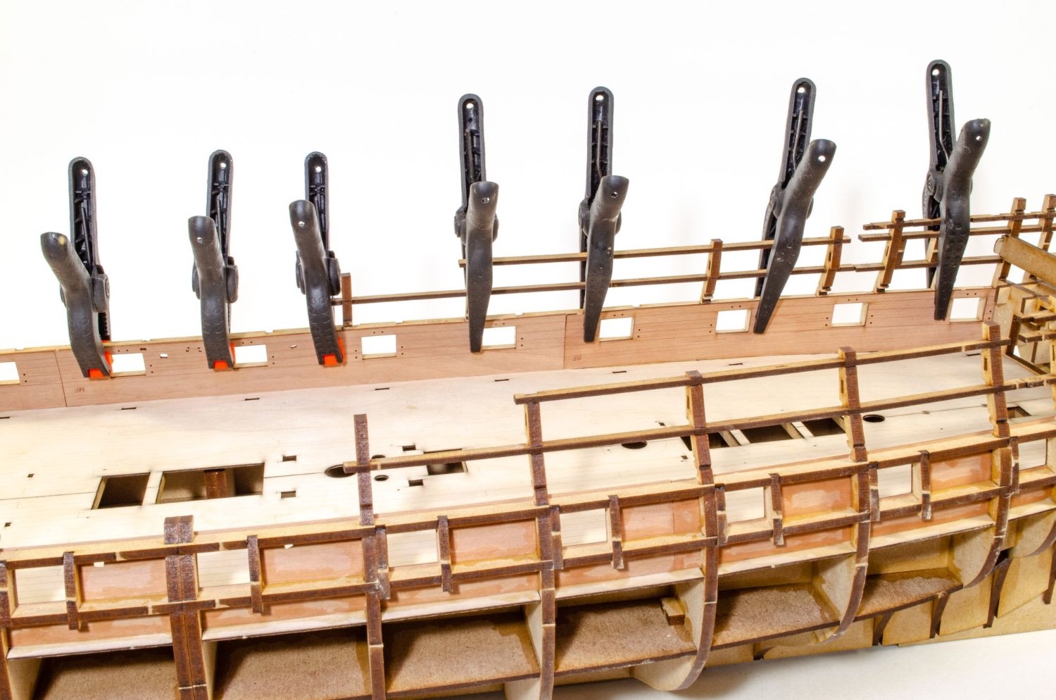
Each 1mm interior bulwark is split into four easy to manage sections. To lessen any load on the frames, so as not to cause any spread in them, all inner bulwark parts were soaked for 30 mins before clamping into place until dry. These were left 24hrs so they were entirely back to their normal size. Pear swells a lot in water, so it's vital you know, beyond doubt, that there's no swelling left. Once dry, all parts were carefully aligned to the port frames, glued into place, and clamped until set.
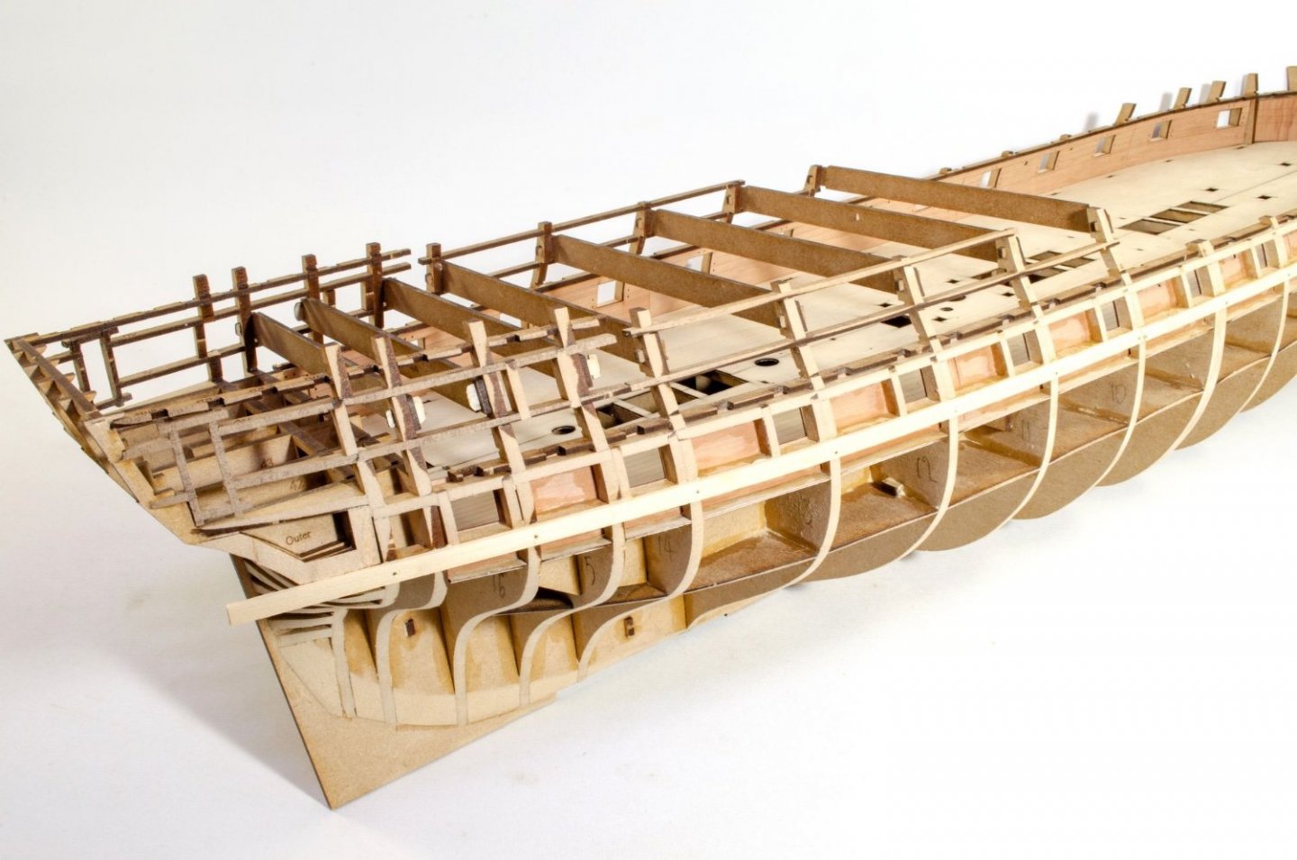
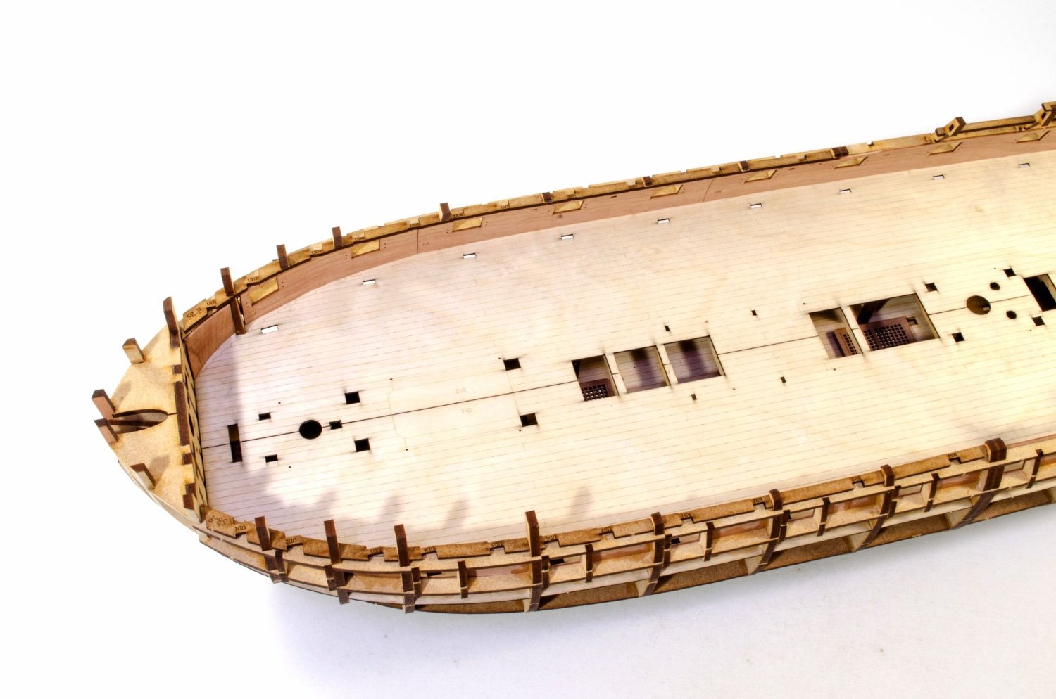
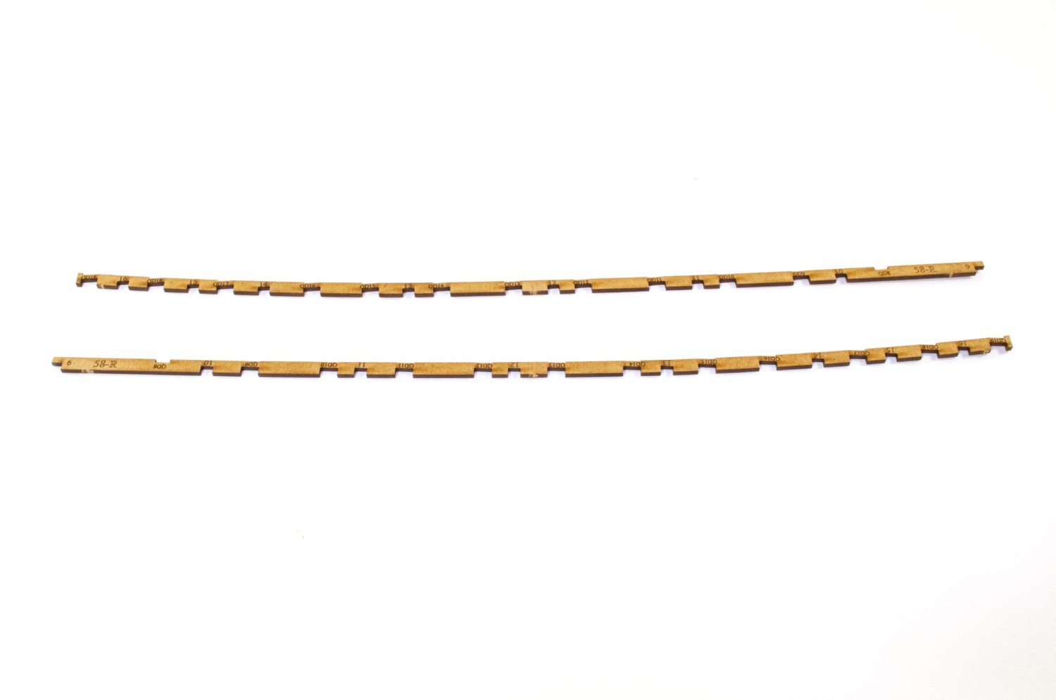
Provision now needs to be made for the eventual deck beam positioning. This is done using some 2mm MDF frames which slot into the bulkhead beams, above the inner bulwarks. There are two per side. These fit with a nice, reassuring push, but at this stage I don't glue them.
A good number of the 6mm pear deck beams and 5mm boat beams are now sotted/hooked over the MDF parts I just installed. This is done to check that the position of those MDF parts are absolutely in the right place. These beams are NOT glued in yet, obviously. At this point I've also reinstated the MDF temporary beams across the quarterdeck bulkheads. Again that's just to make sure every dimension is exactly as designed.


Once happy with everything, the MDF deck beam mounts are brush glued into place.
Lastly, the pear beams are removed and carefully put away somewhere safe. The temporary MDF beams remain in place to help me with the hull fairing, and that's the next job.

That's all for now.
-
4
-
-
Continuing today's update:
Time to get rid of that blank section in the last bulkhead. That was there to protect the bulkhead while work was being done on it with shaping the stern. A gentle twisting removes this from the hull.
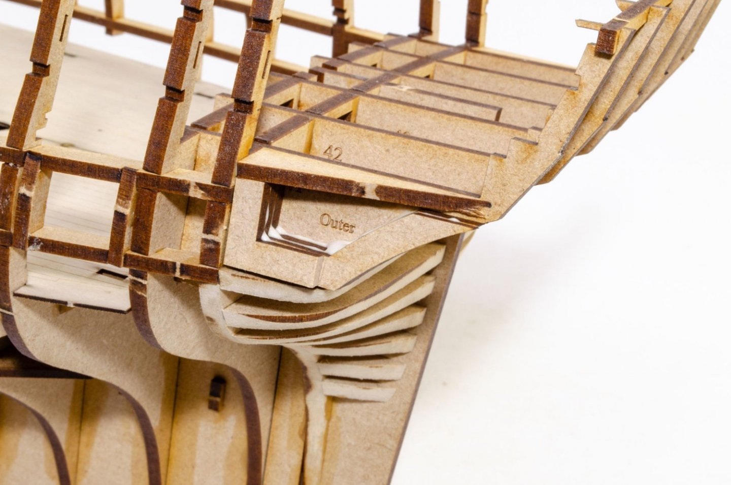
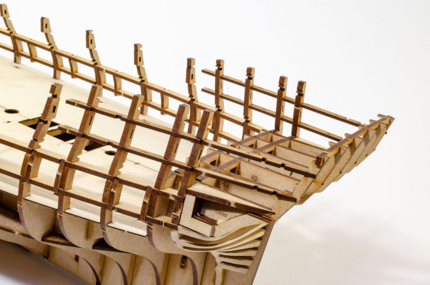
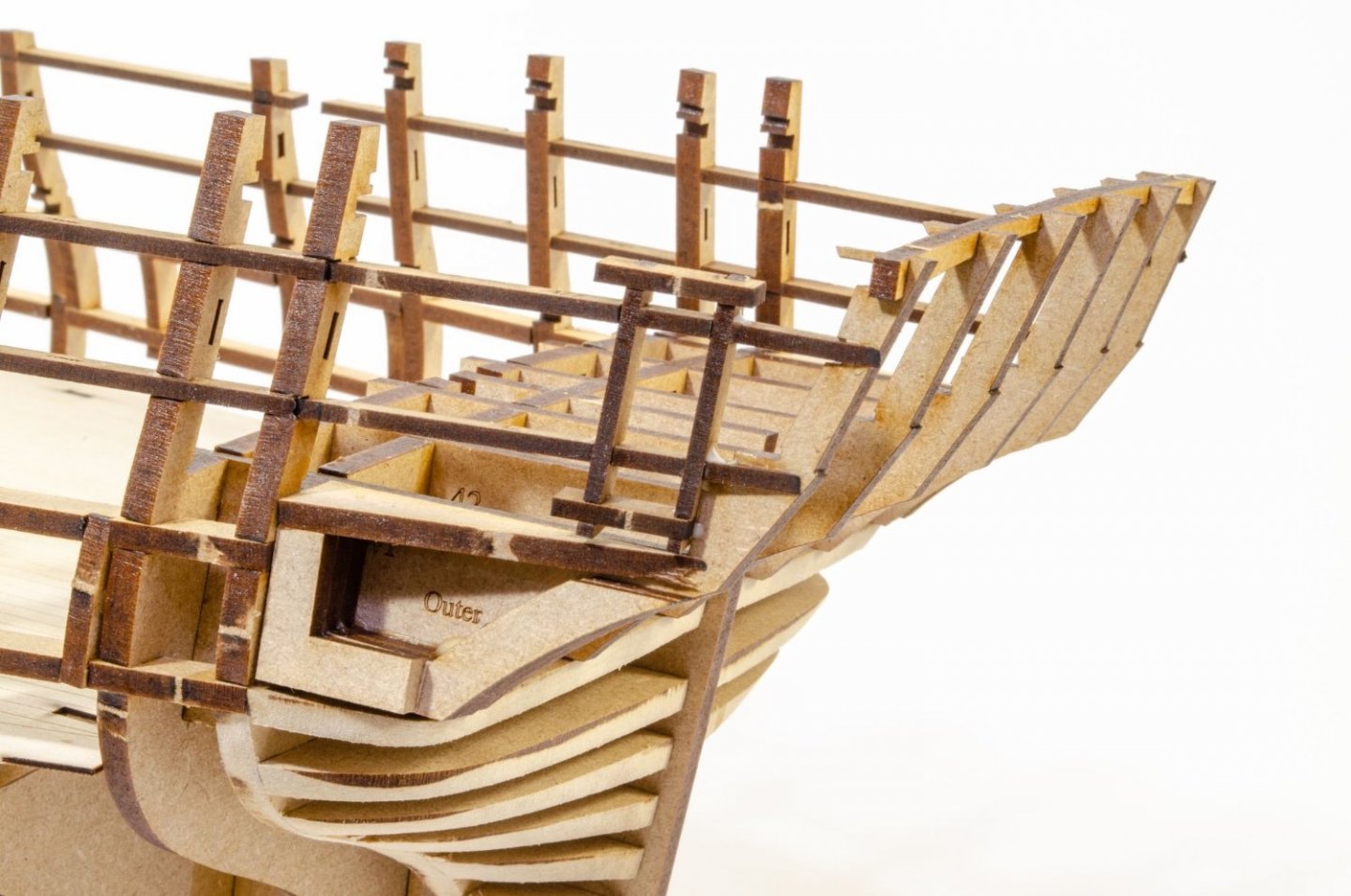
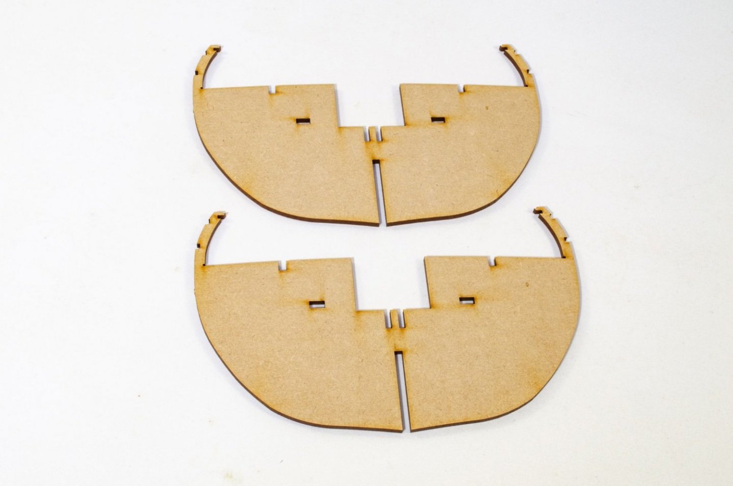
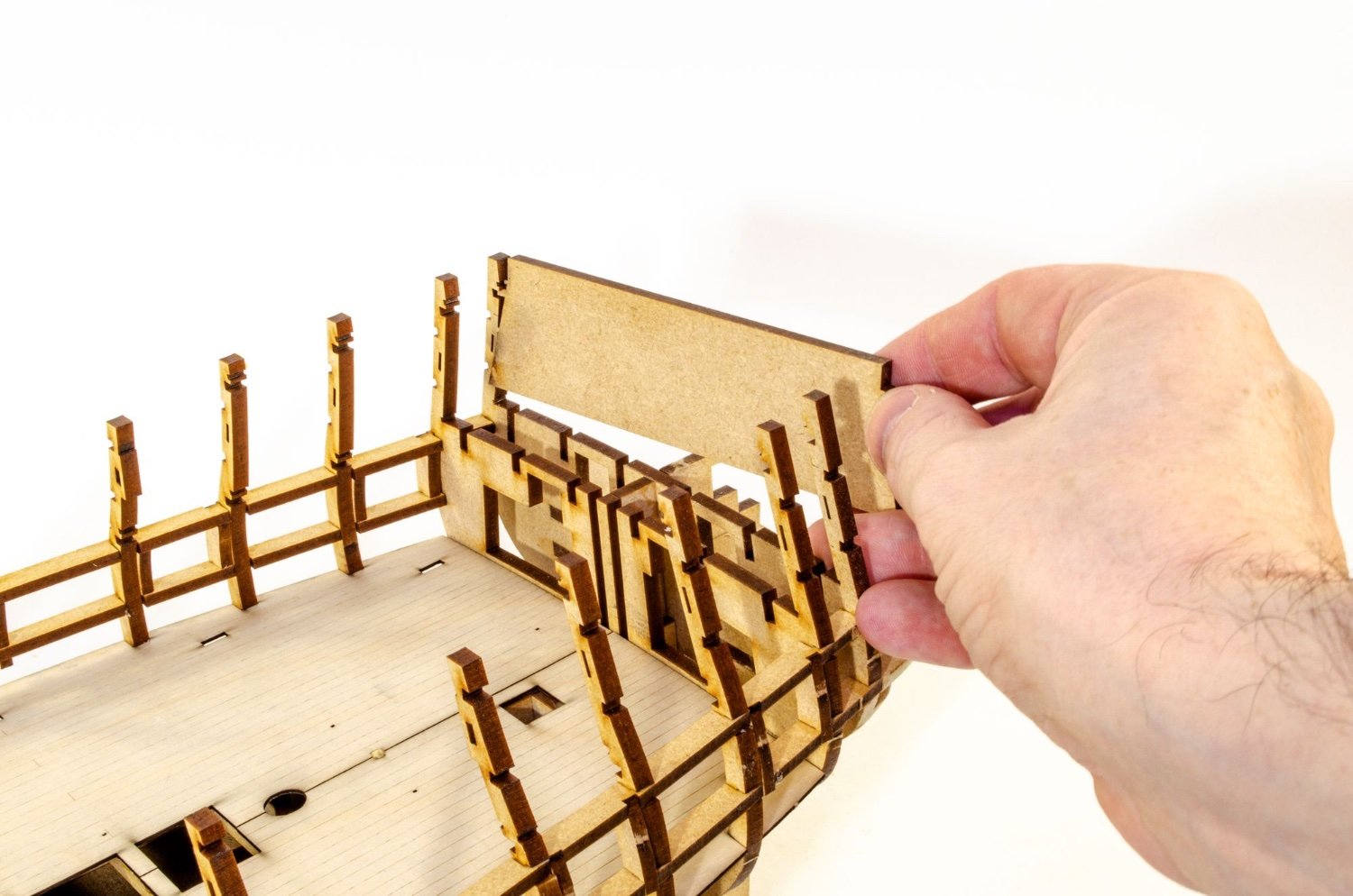
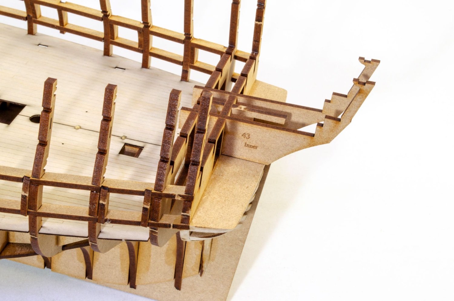
Time for the stern timbers to be fitted. These slot across the rear two bulkheads, creating the correct angles for the parts. They also sit on the shaped stern upper block. First the inners, then the middles, followed by the outers.

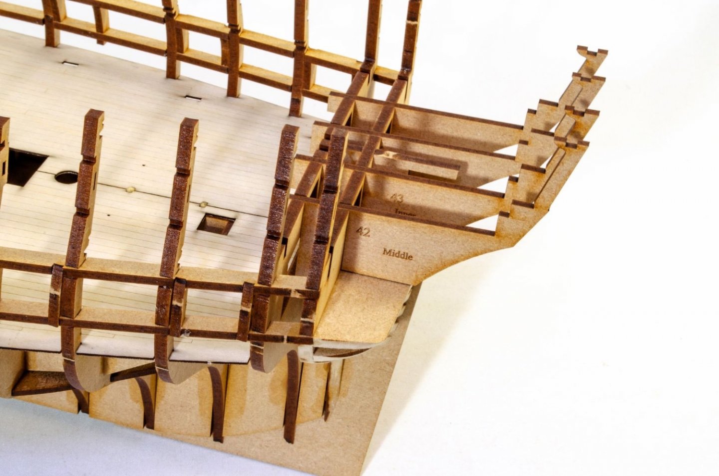
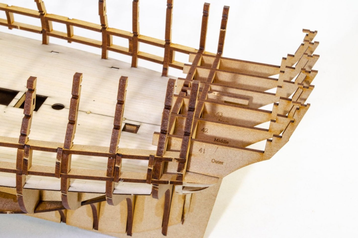
Some filler blocks are now added to the outside of the outer timbers, creating the rest of the platform and something to plank to also.
Those fragile rear bulkhead ears are now bolstered with the addition of more longitudinal strips, all slotted to fit. The gap you see between some of them is to house the fore bulkhead screen. That's designed so you get zero gaps. You'll see that later in the build.

Door frames are added from the captain's cabin to where the quarter galleries will eventually fit. Once dry, the inner horizontal parts of the frames are cut out.
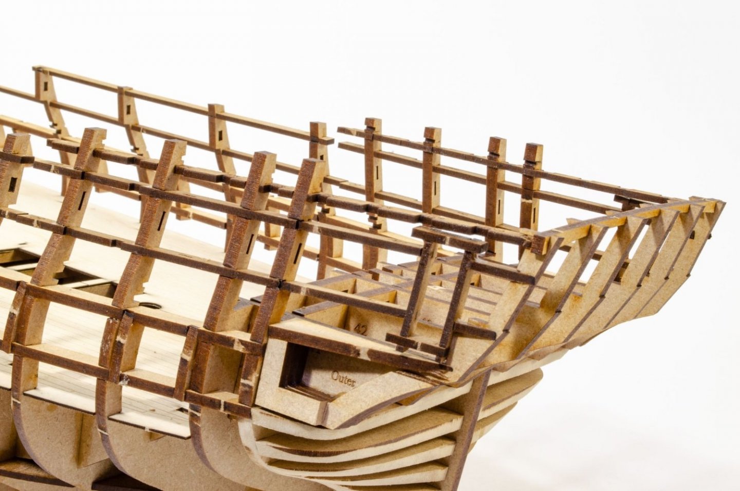
Part of bulkhead 18's ear is now cut out as this is the only one that would obstruct the gun port. That is sawn out and filed flush before the last gun port frames are glued in.
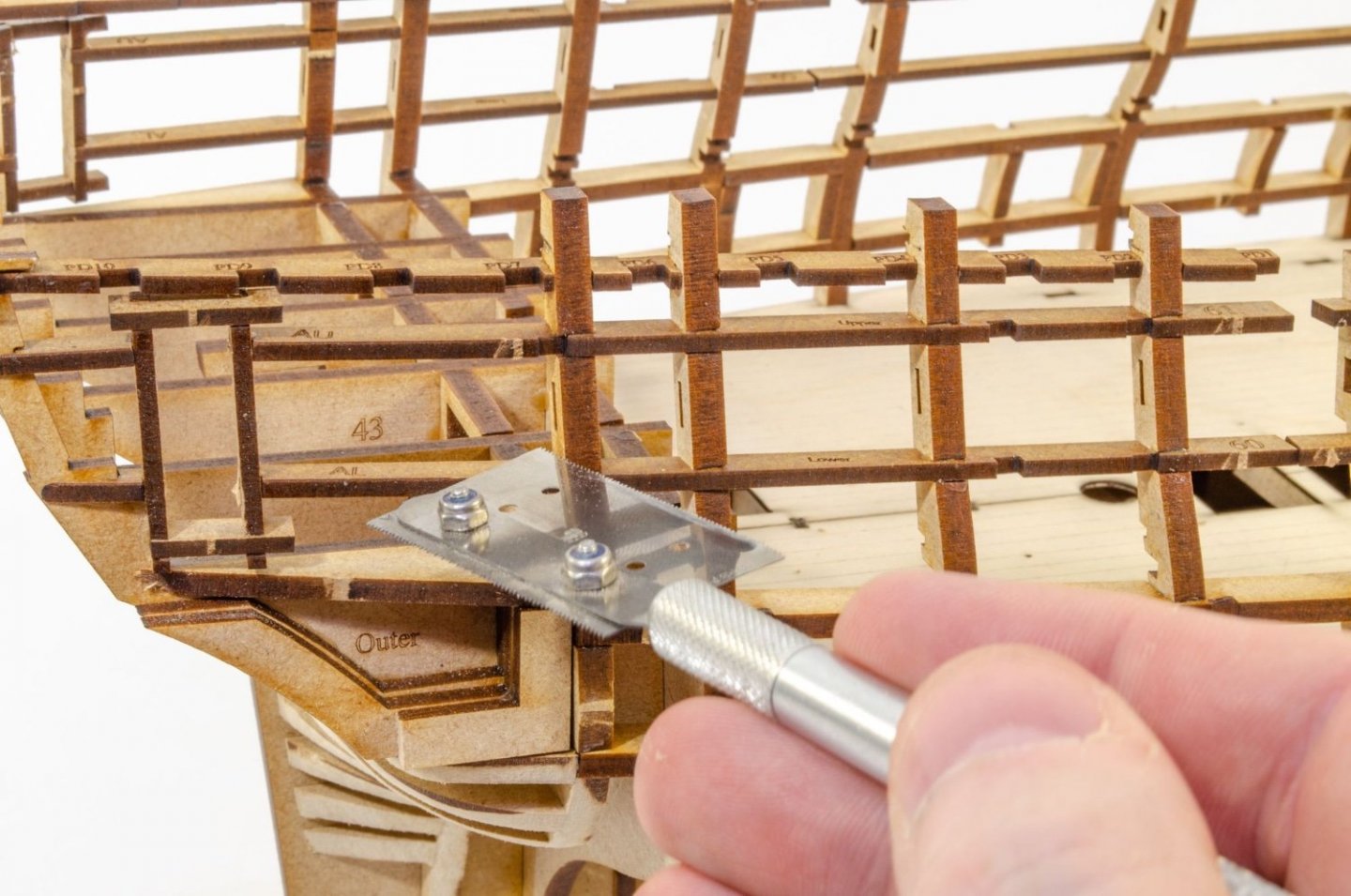
To create a rigid structure for fairing, the rear of the hull has some temporary MDF sections that are held in place with pegs. These are totally solid and shouldn't come loose.
And that is it for today. I'm whacked!
-
2
-
-
Time for another Lego update.
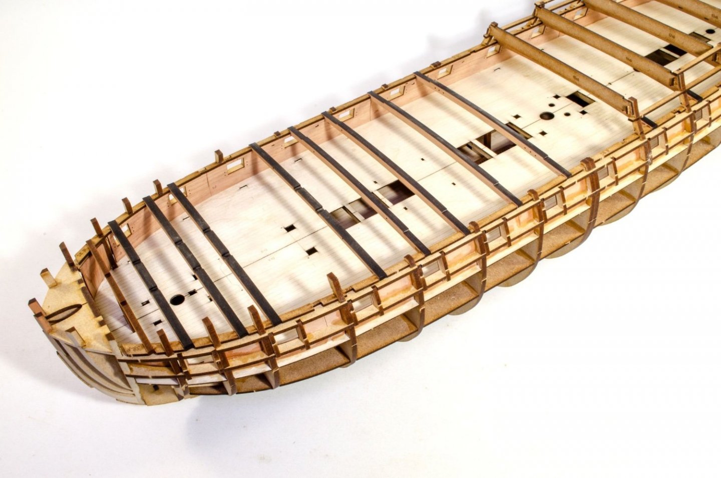
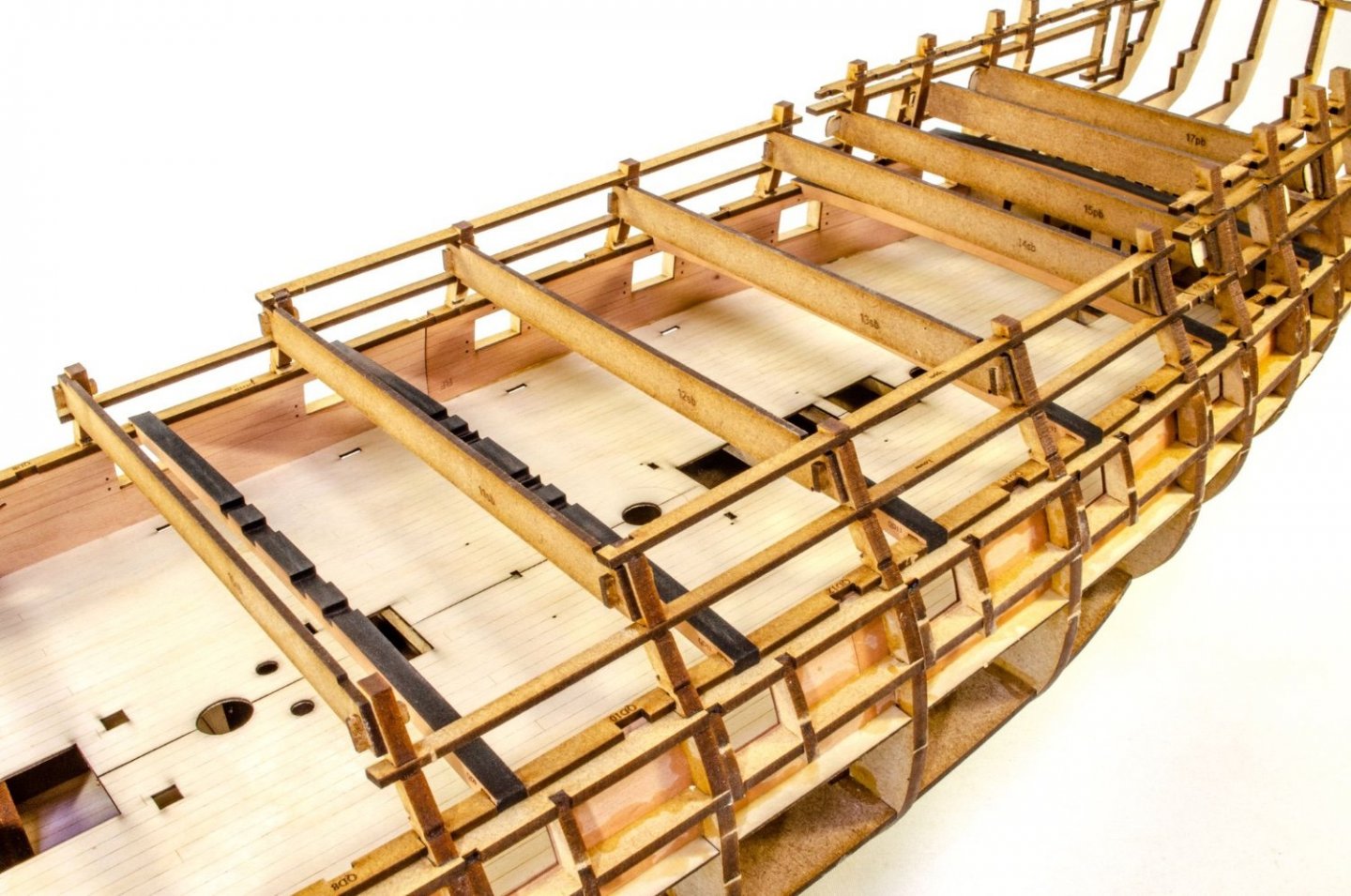
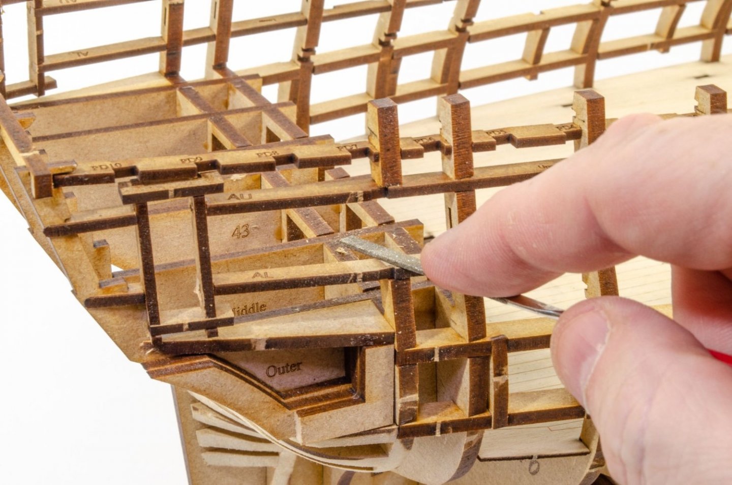
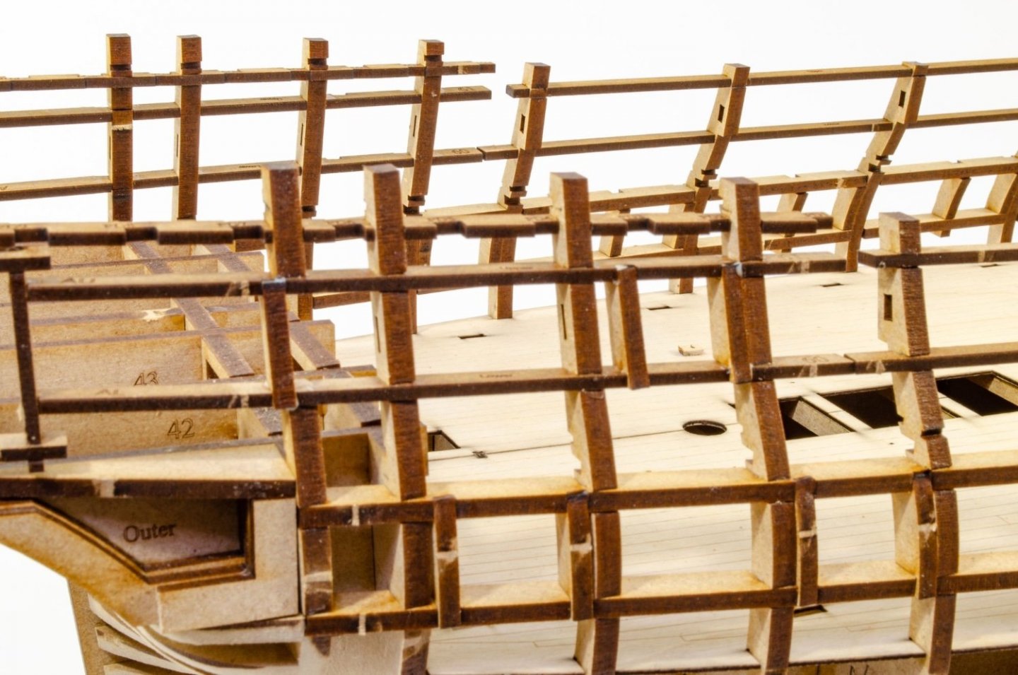
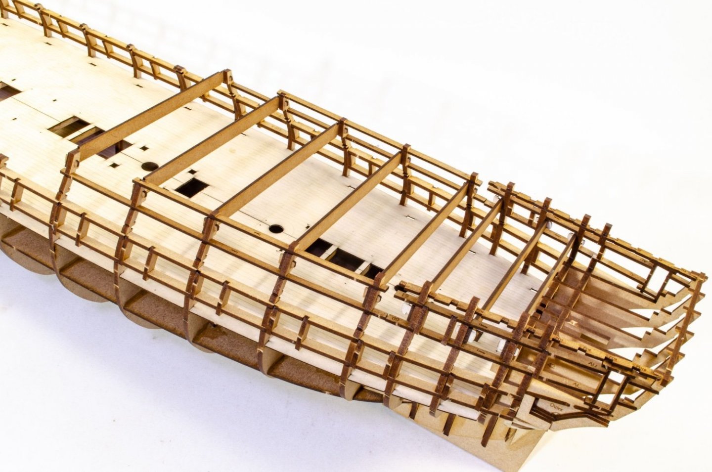
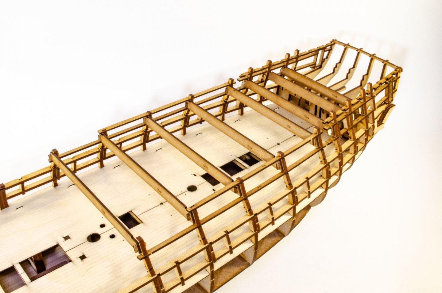
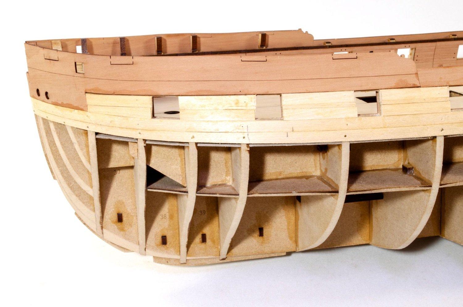
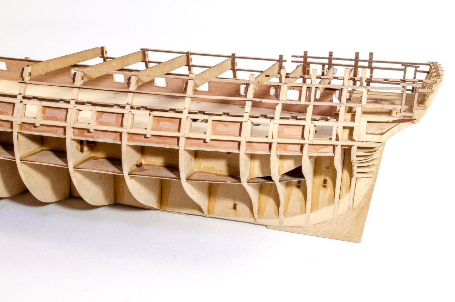
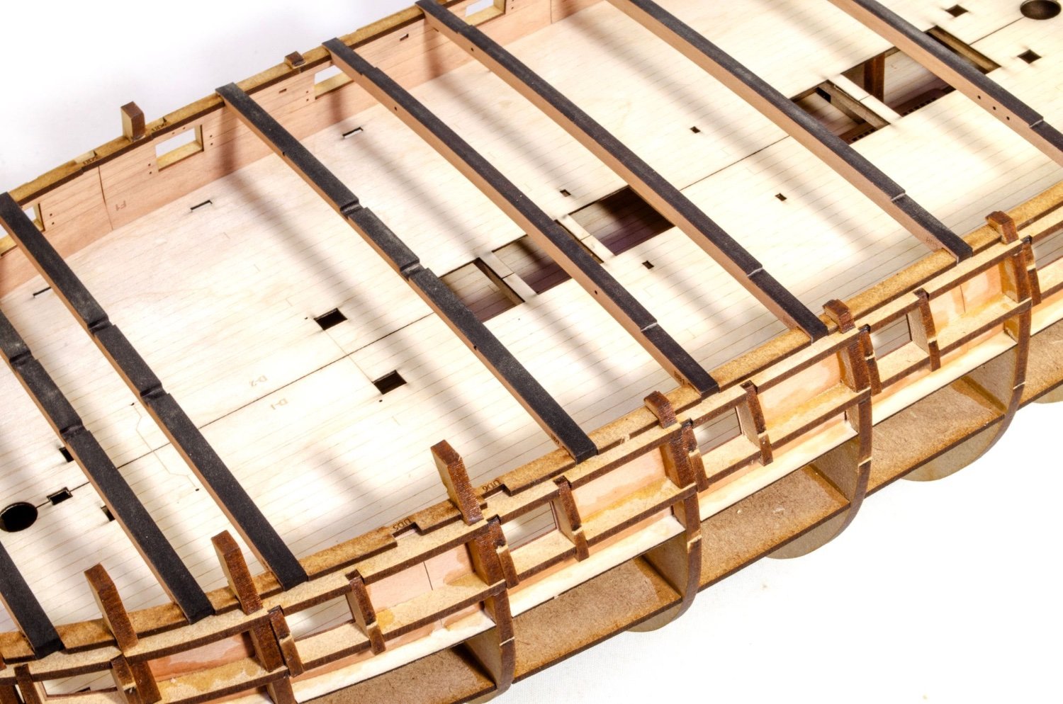
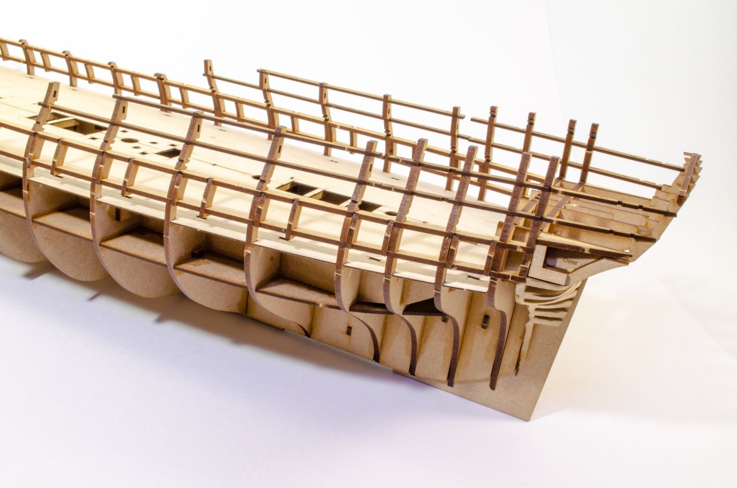
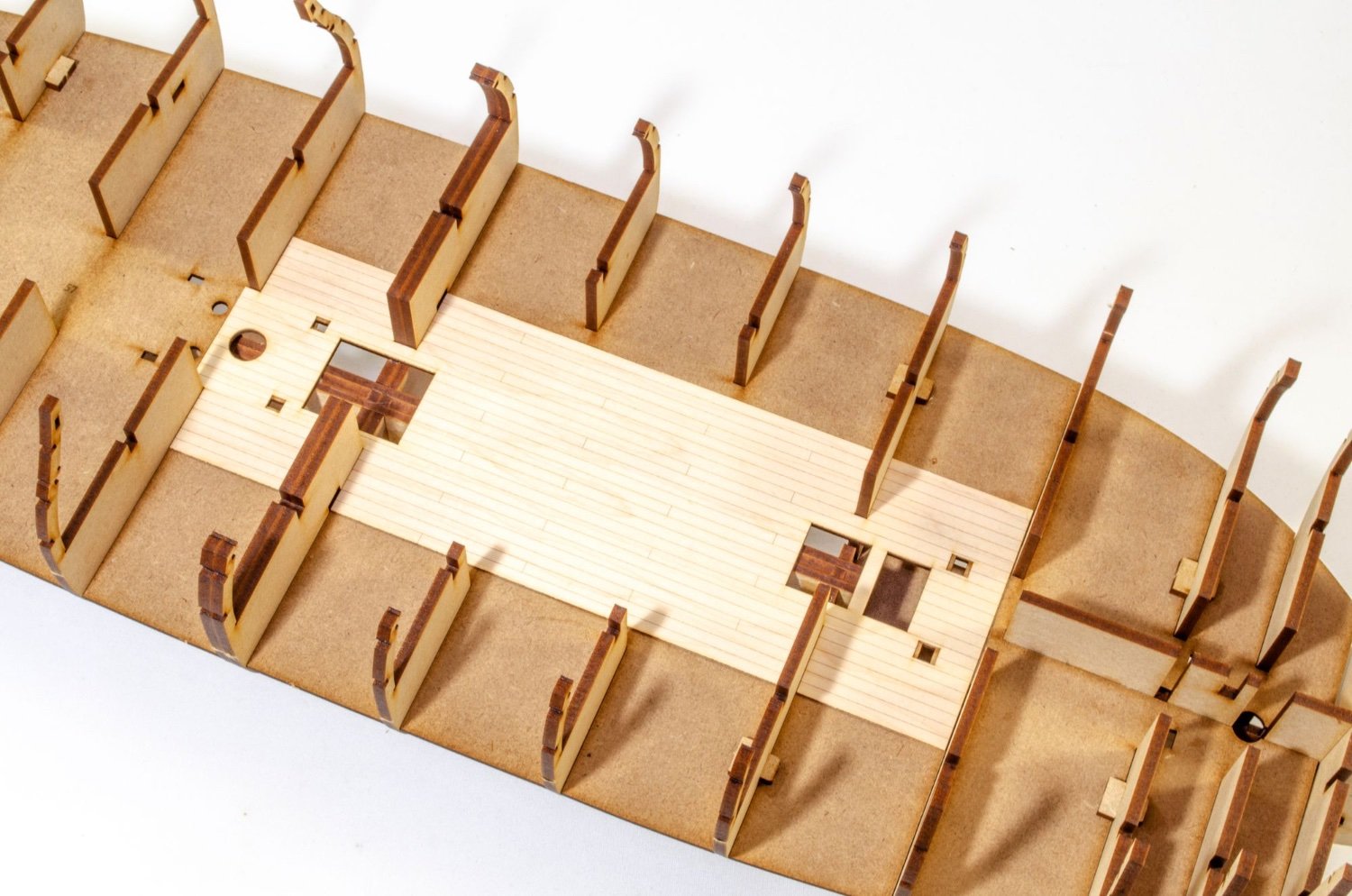
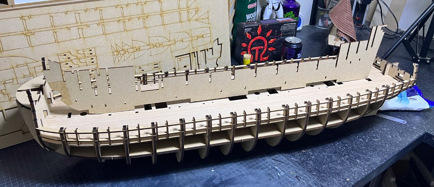
Next job was to bolster those bulkhead ears by adding the gun ports. As with Sphinx, these are built into the frame. The main gun deck longitudinal frames lock into the bulkheads and comprise two parts upper per side, and two parts lower. Lower in first of course.
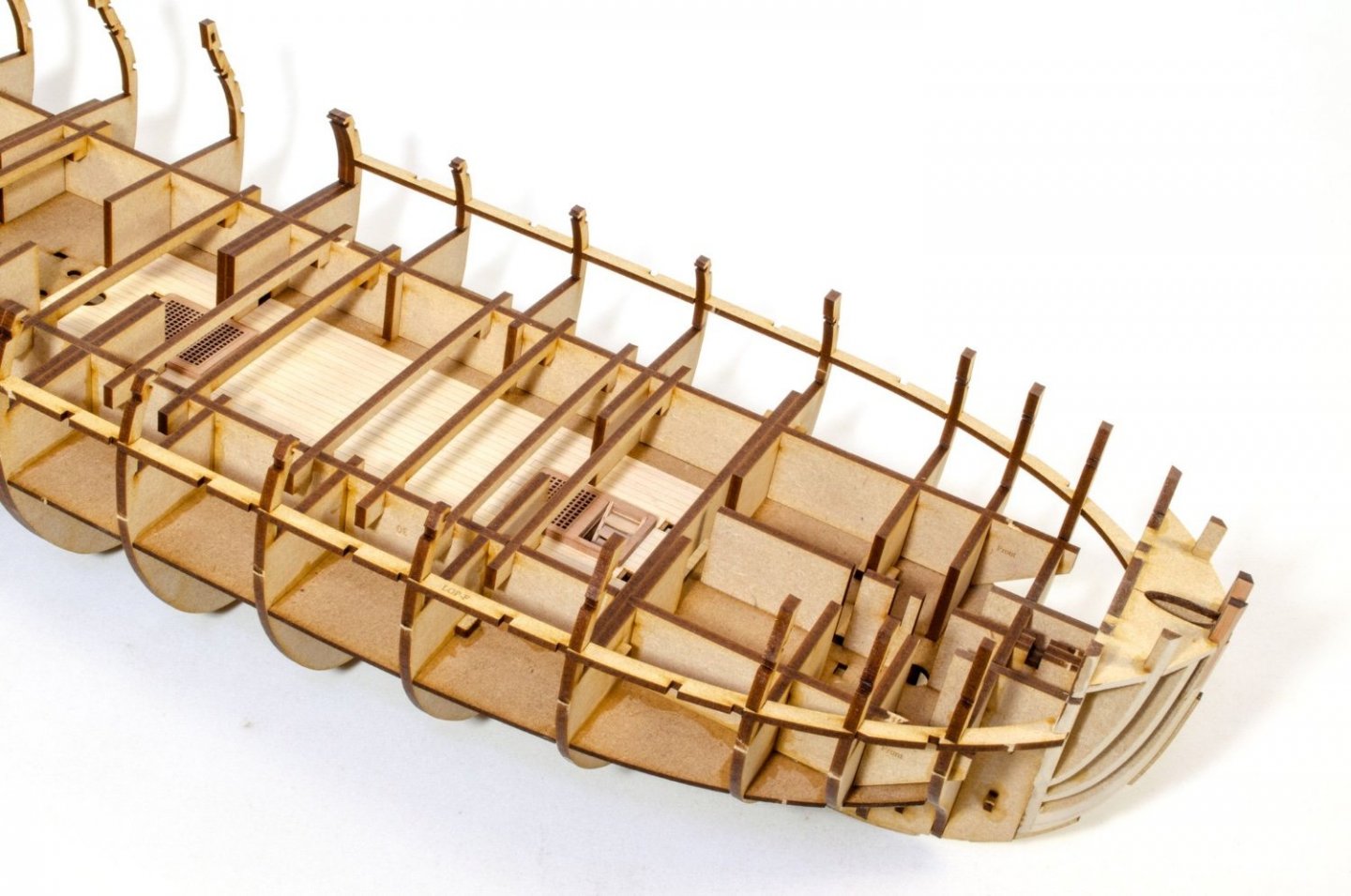
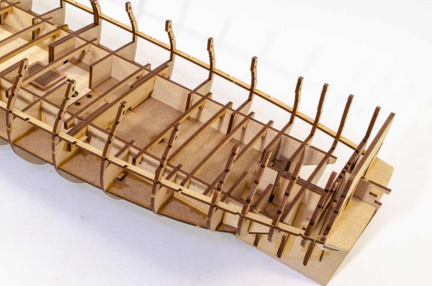
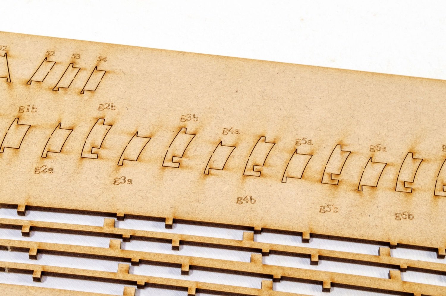
The vertical gun port frames now need to fit in. These are all specific, to suit the curve of hull. Each port has two verticals apart from #7, as that one uses the side of a bulkhead for the other vertical.

The main gun deck ply layer is pre-engraved to help you with laying the planks. It's also supplied in halves, to make it easier to fit. Both deck halves are turned upside down and a strip of narrow tape is applied full length, and then the various openings cut out. The deck is then turned over and bent down the tape hinge before being glued into place. Deck edges lock into slots in the base of the bulkhead ears, so there's no problem with it popping up. It's just a case of making sure it's glued down across the deck beams and then weighted down while it dries. No need to pin anything here.
-
3
-
-
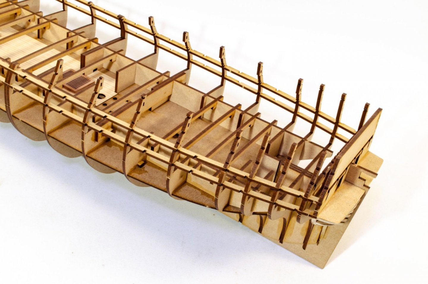
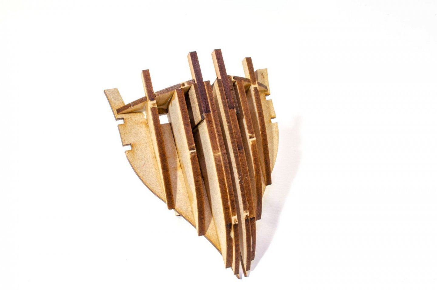
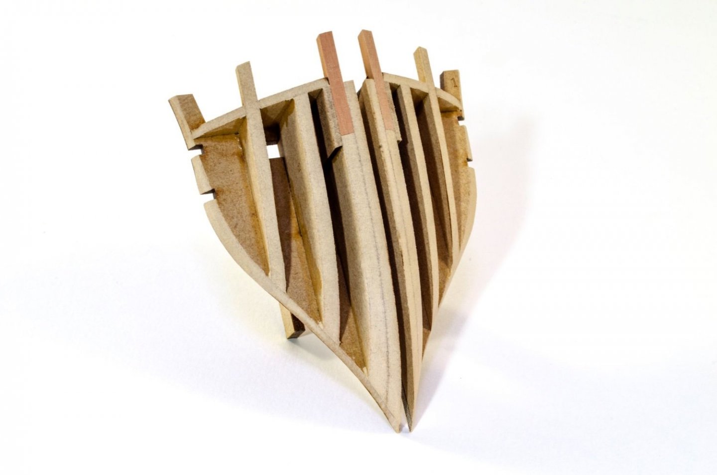
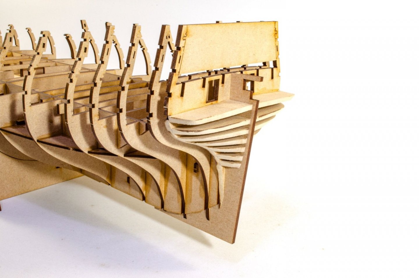
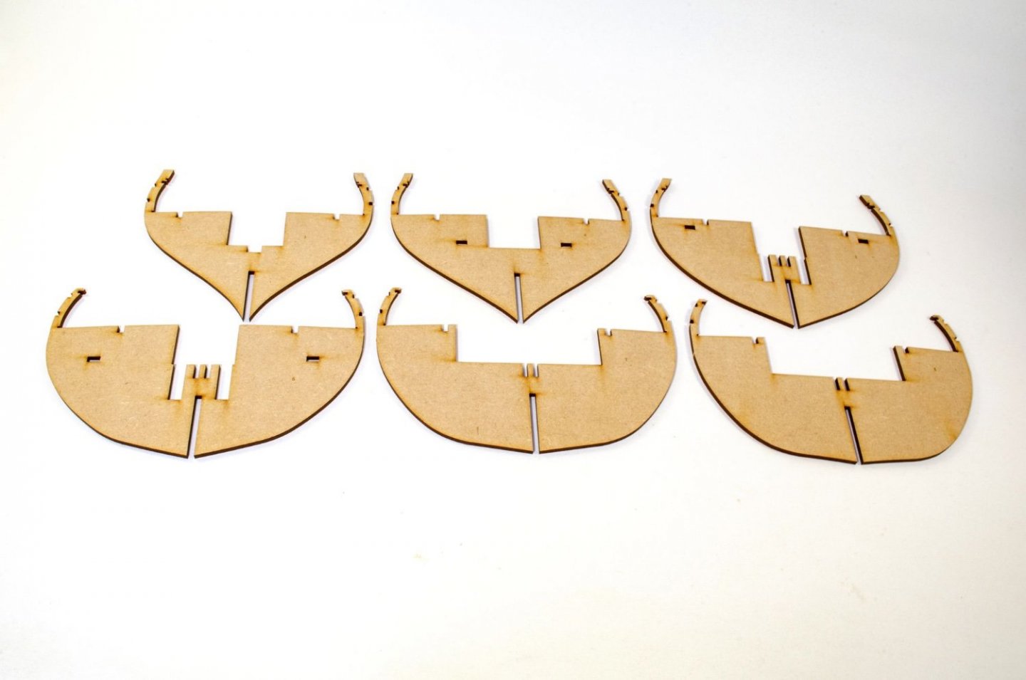
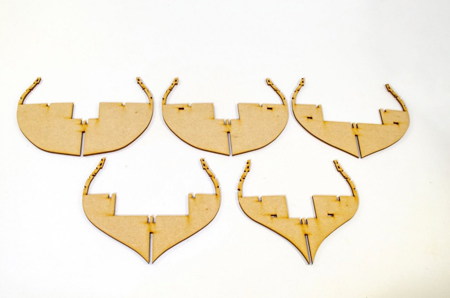
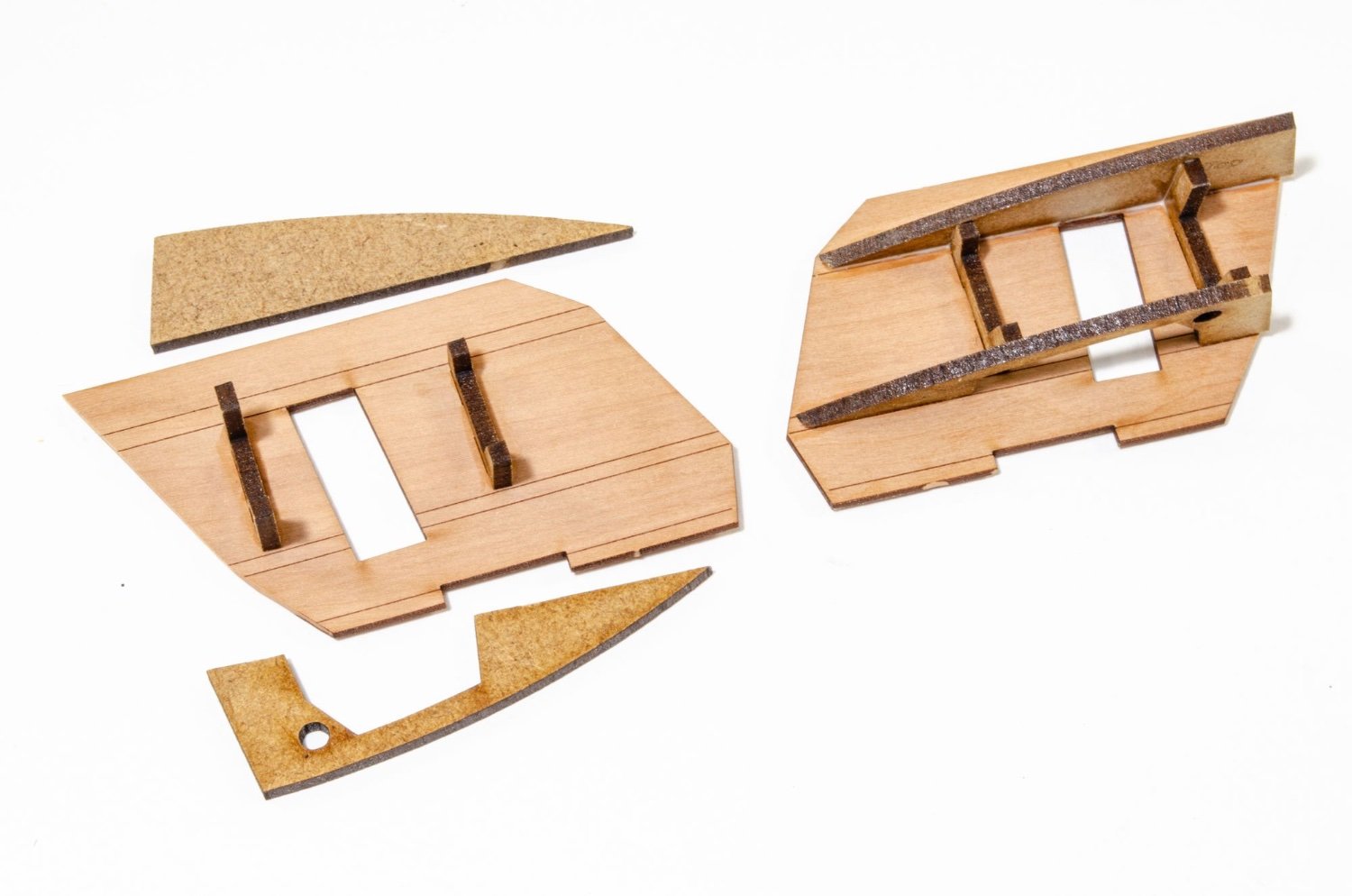
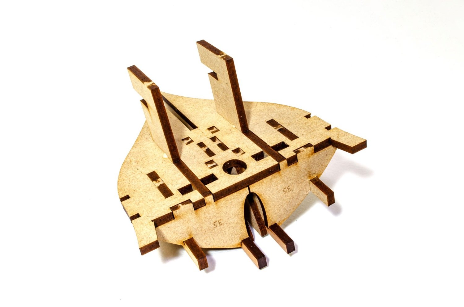
Small update as I hated leaving it without a bow and stern from the last update 😁
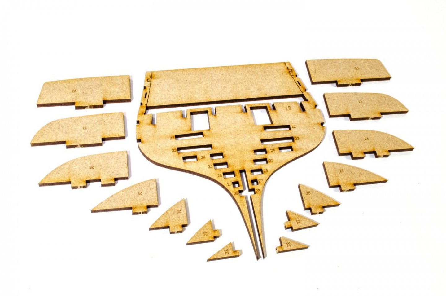
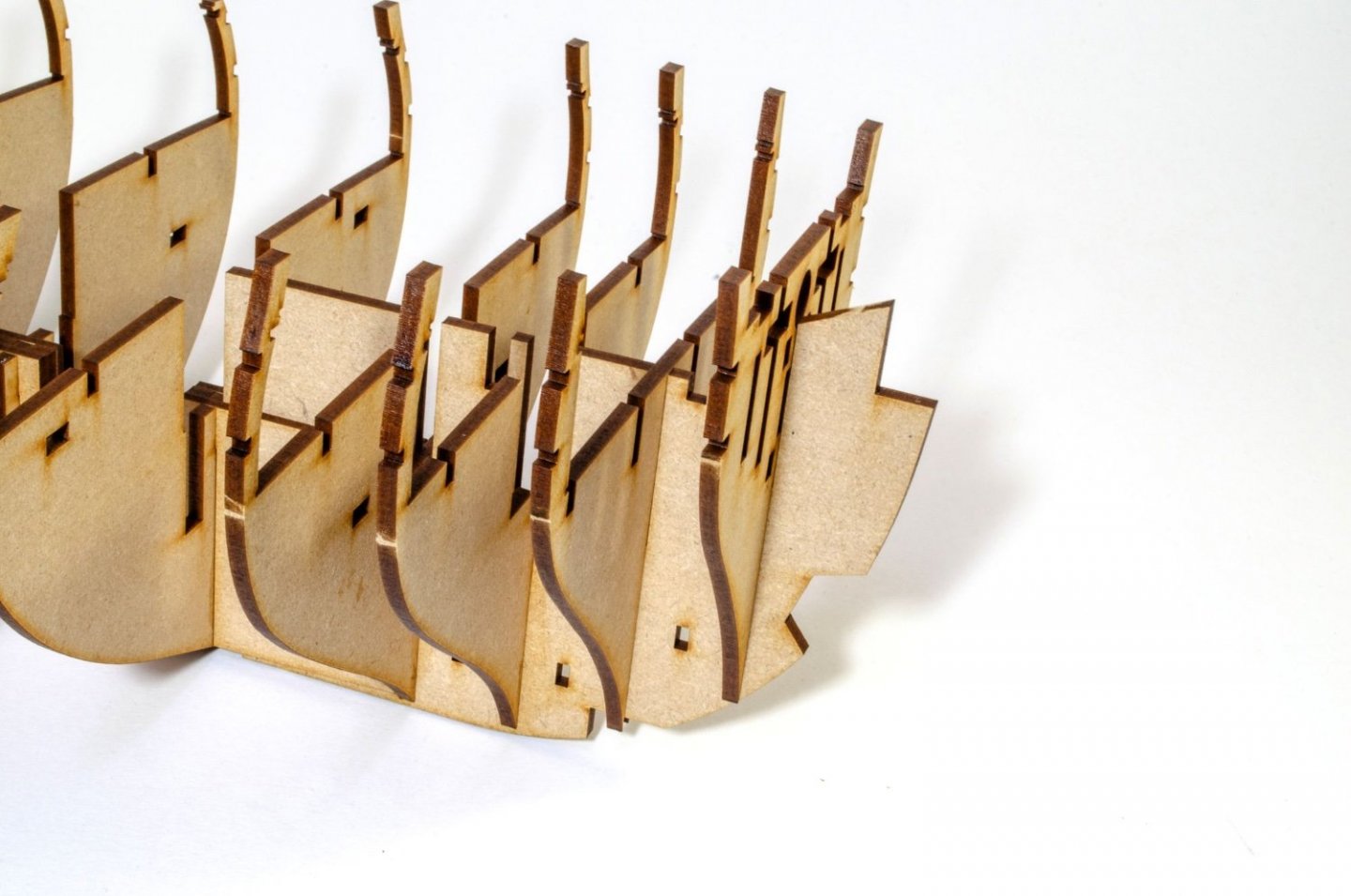
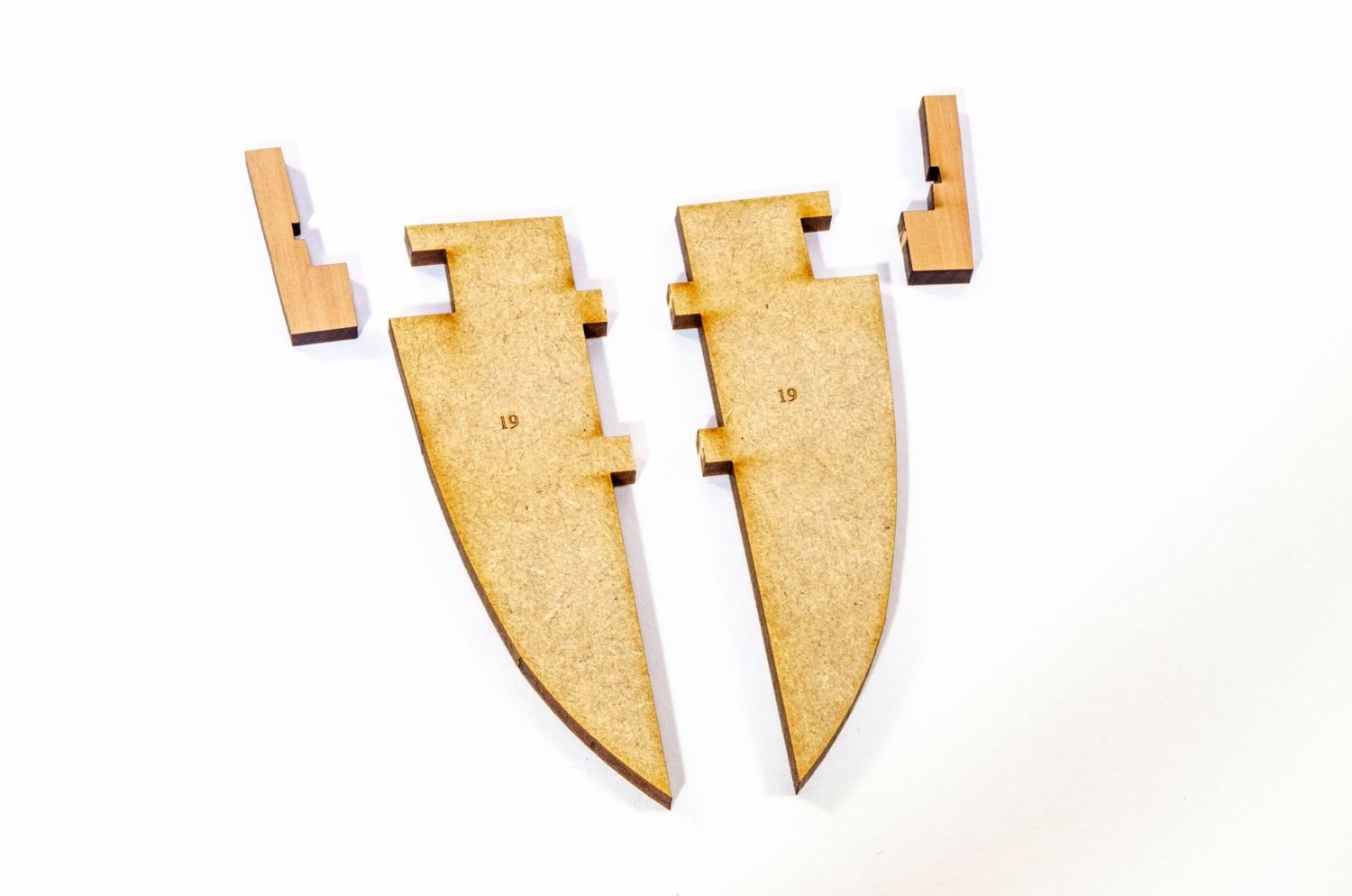
First, the bow. The foremost 'timberheads' near the prow are pear inserts to the MDF former so there's lots of strength up front when later work is carried out. Bulkhead #1 is temporarily fitted to the hull and then the formers are fitted in. The reason for doing this on model is so I can get the innermost formers snug against the keel. All these parts are numbered and the relative slots on the bulkhead are numbered too.


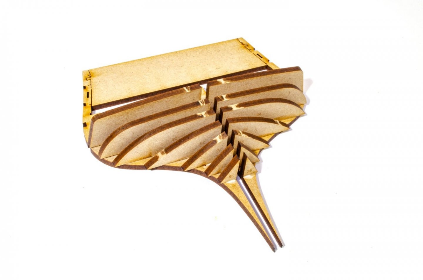
The assembly is now removed from the hull before the outer formers are set and the upper parts (35) are glued into place as seen here. Too stiffener pieces are also glued to the exposed side of the pear inserts. The assembly is now left to properly dry.


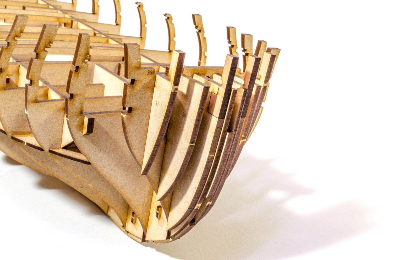
A sanding block is now taken to the bow and the whole lot is sanded and shaped in readiness to fit to the hull. The back side of this also hooks onto bulkhead #2. When I was happy with this, it was glued to the hull.
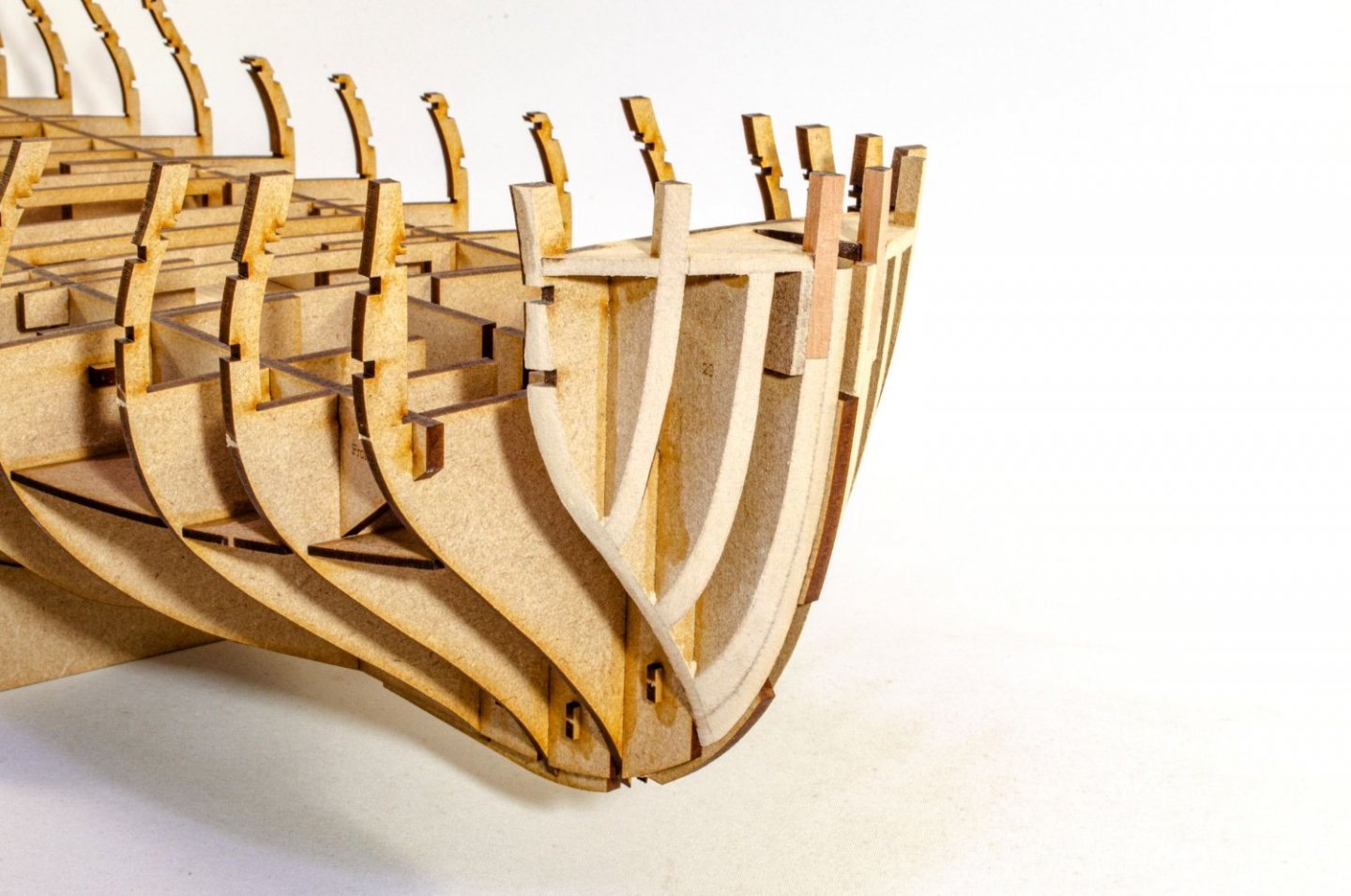
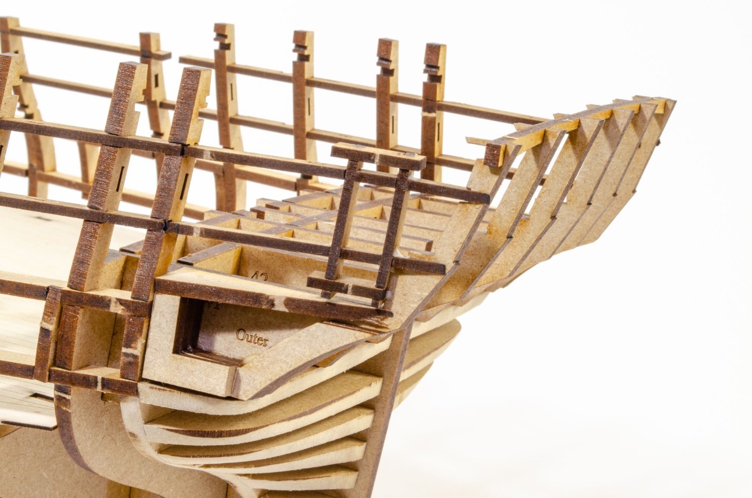
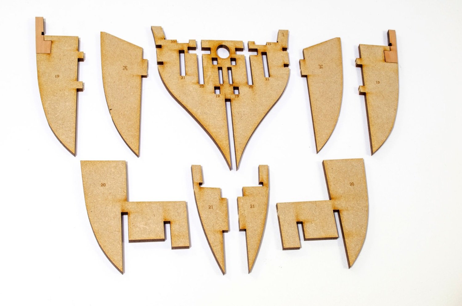
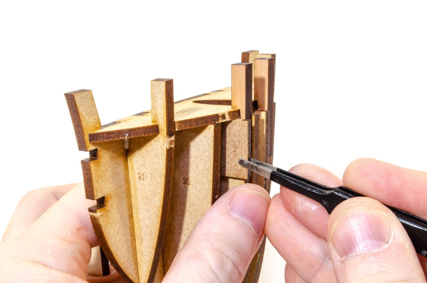
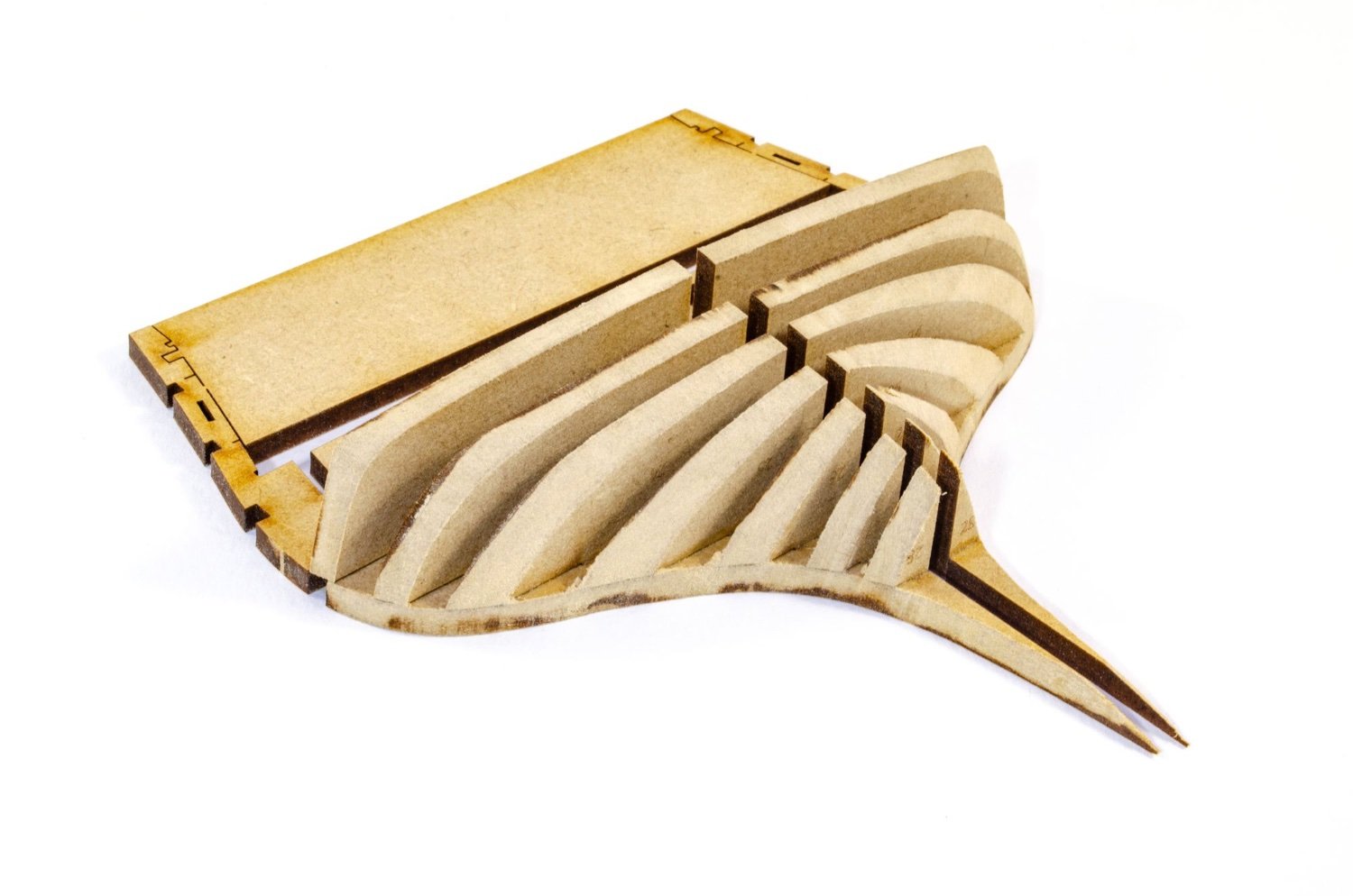
It's now the turn of the stern and fitting out the final bulkhead. As with the bow, this is fitted with a series of formers that are numbered in relation to the bulkhead slots. It's a no-brainer!
This is now carefully sanded to shape. It will doubtless be refined later when it comes to fairing the hull. Once happy with it, it's glued onto the hull.

Until later!
-
5
-
-
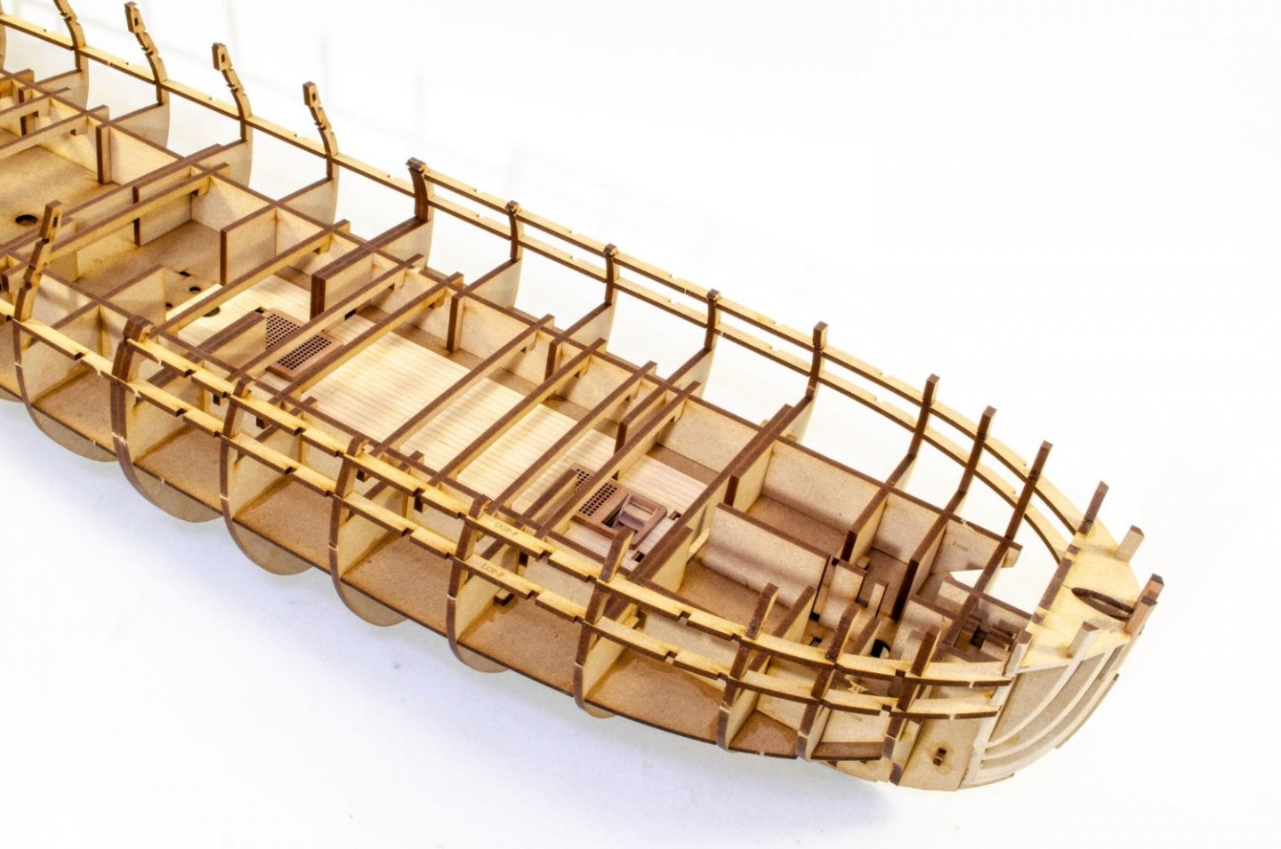
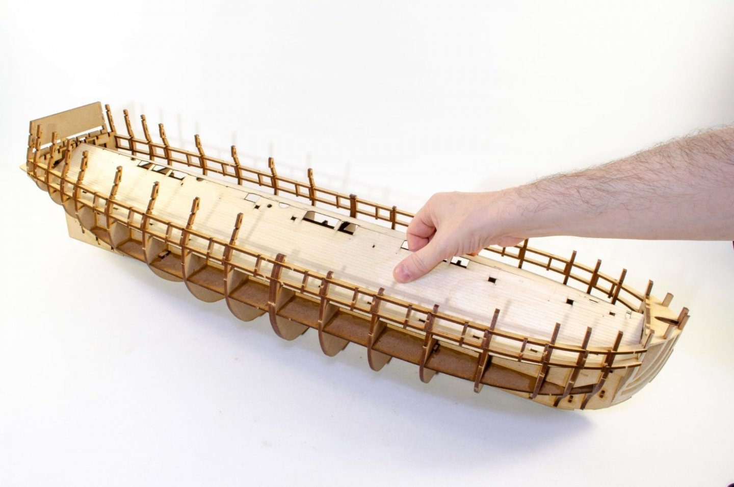
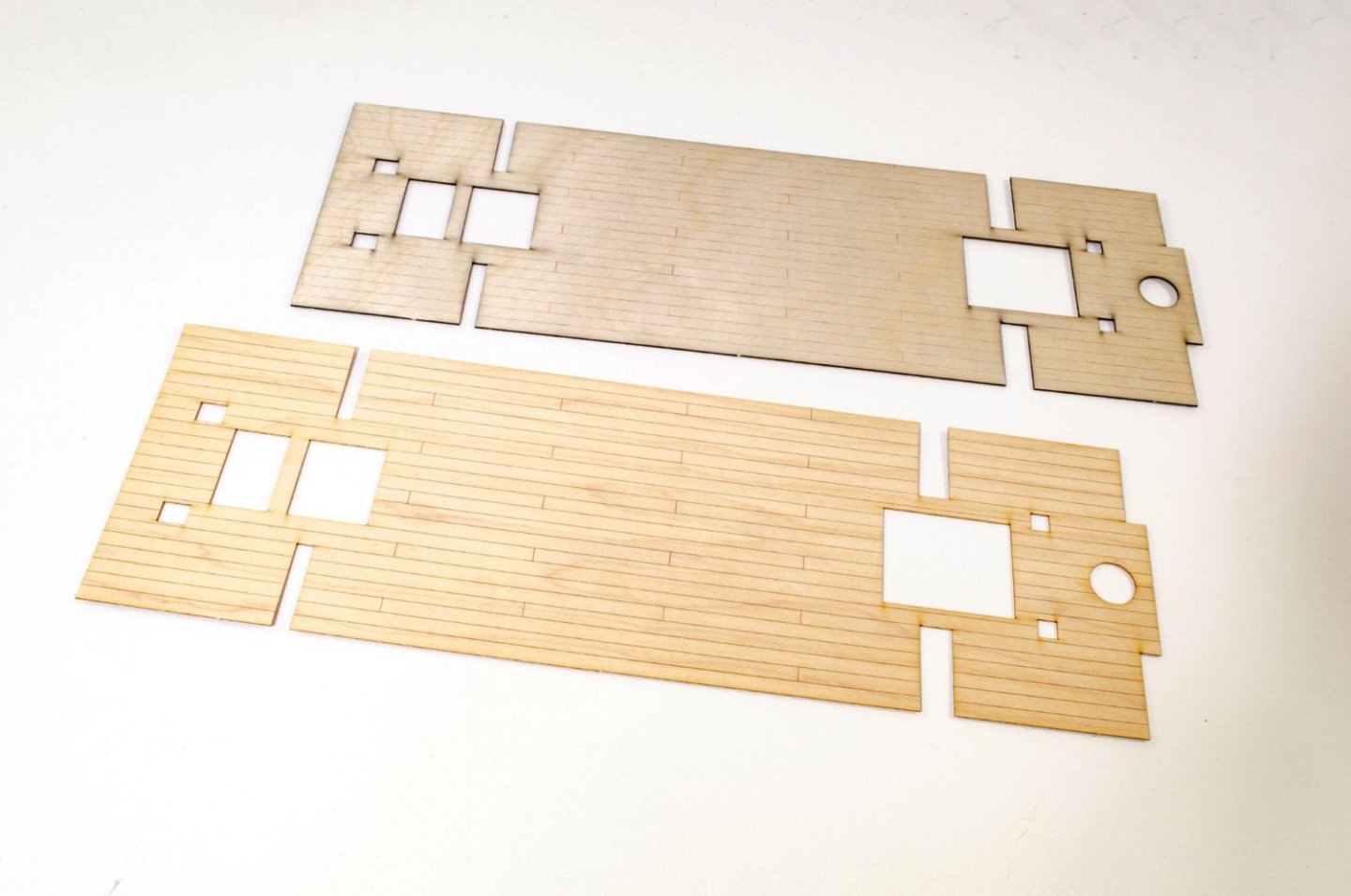
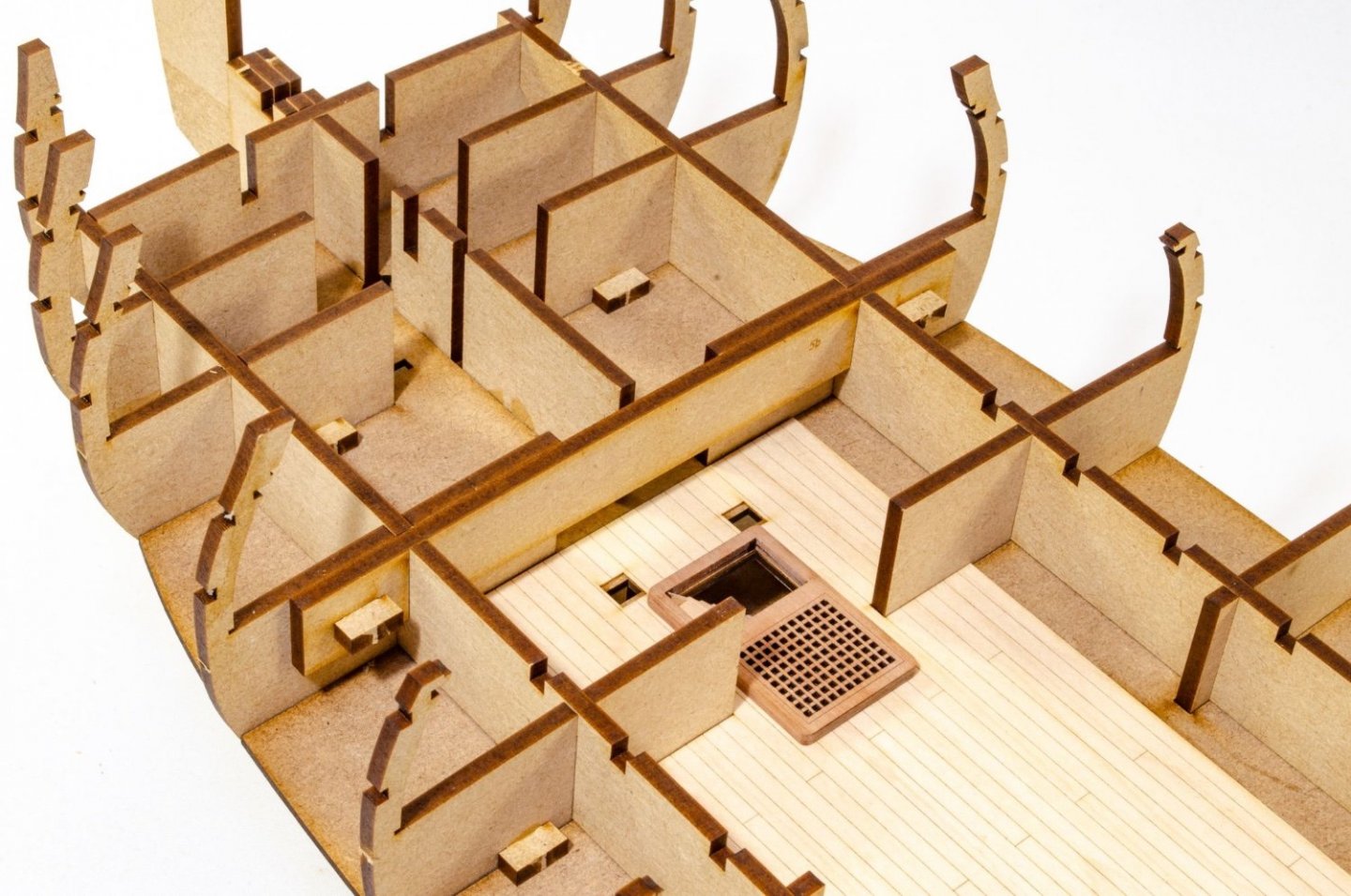
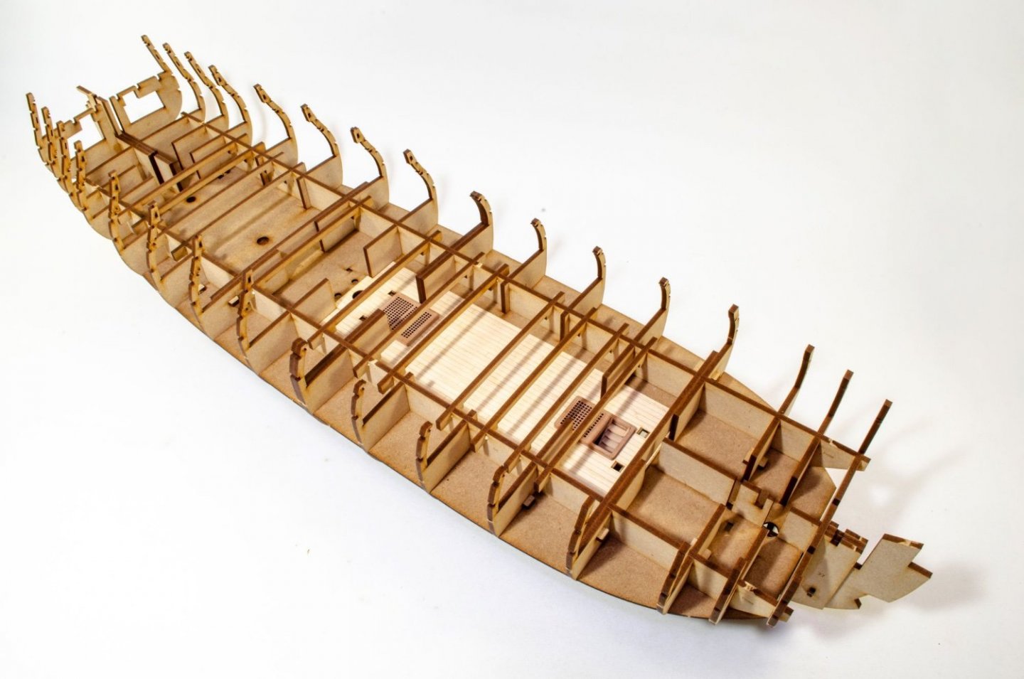
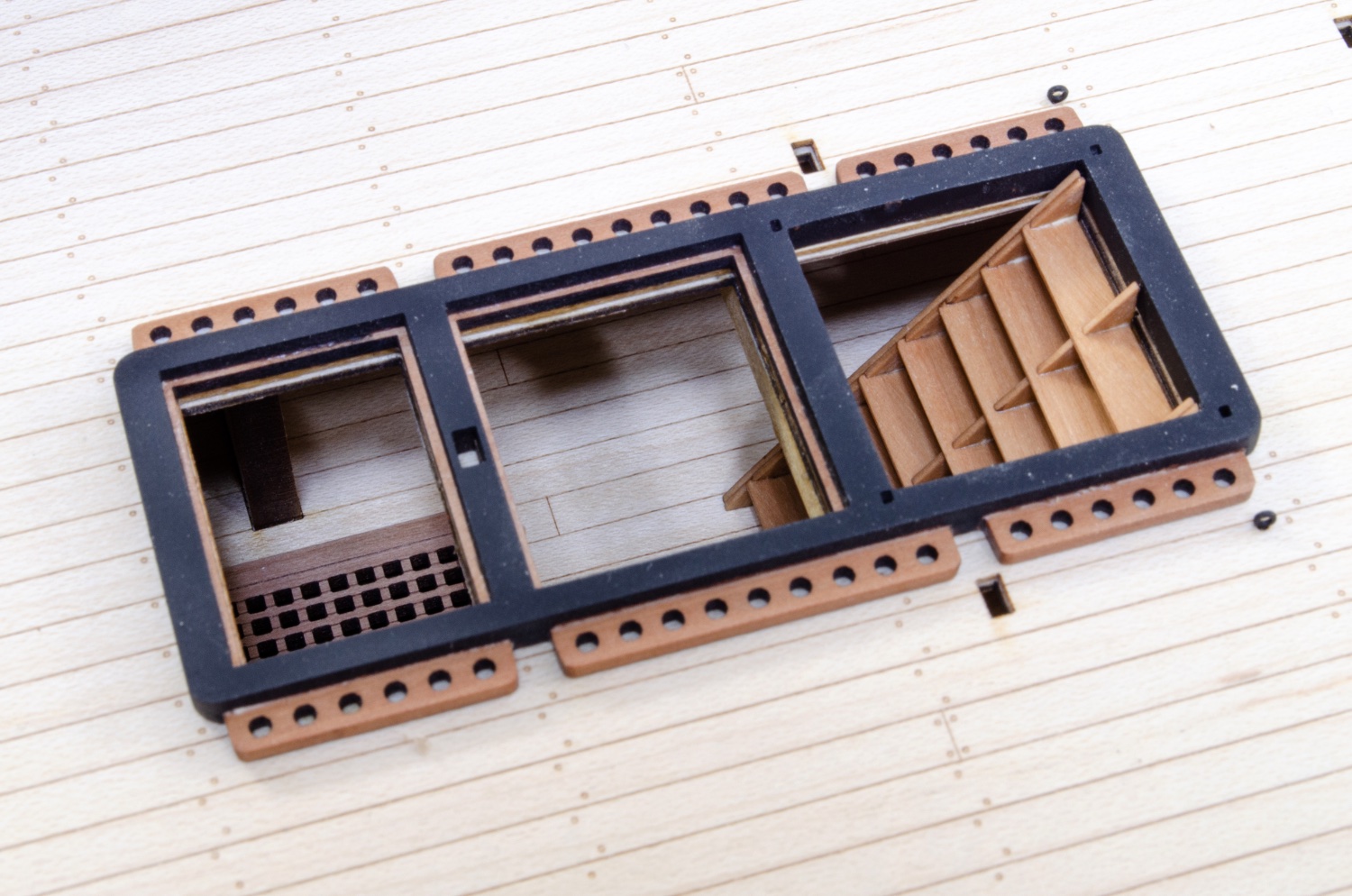
This photo shows the standard ply engraved section for the lower deck. As I've said, you'll be hard pressed to see this stuff, unless you're an ant that's crawled in. But in case you are, or have that endoscope I mentioned, the detail is there in part. Here you see the ply engraved part along with the optional maple deck section which I have opted to use for this build.
The deck section is now glued into place.
Two, 2-part grates are now built and added.
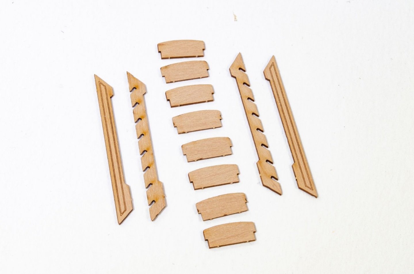
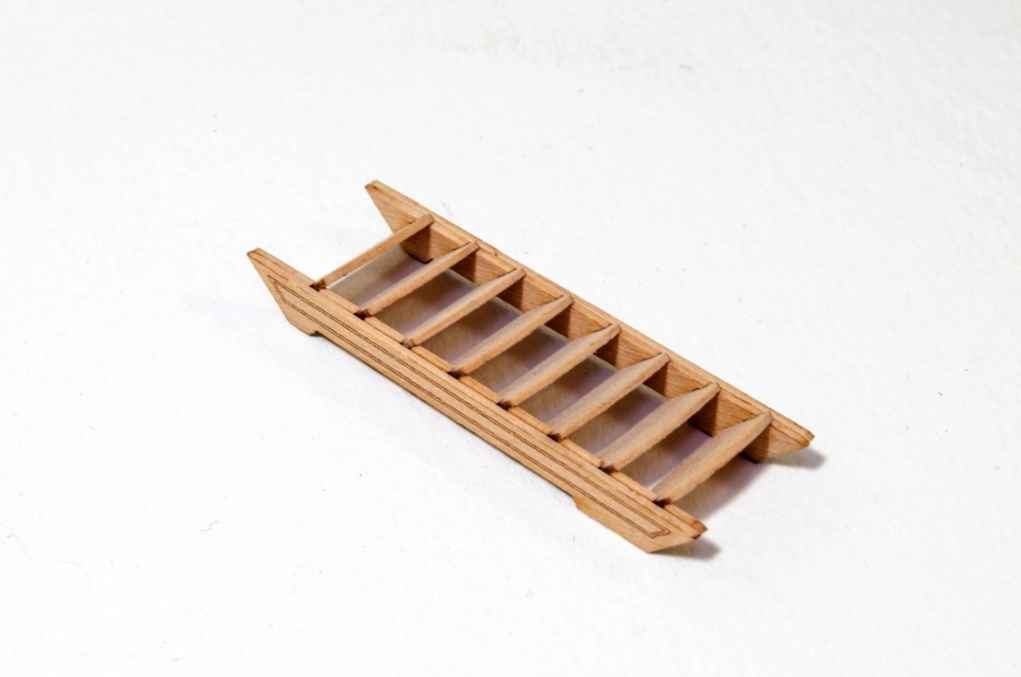
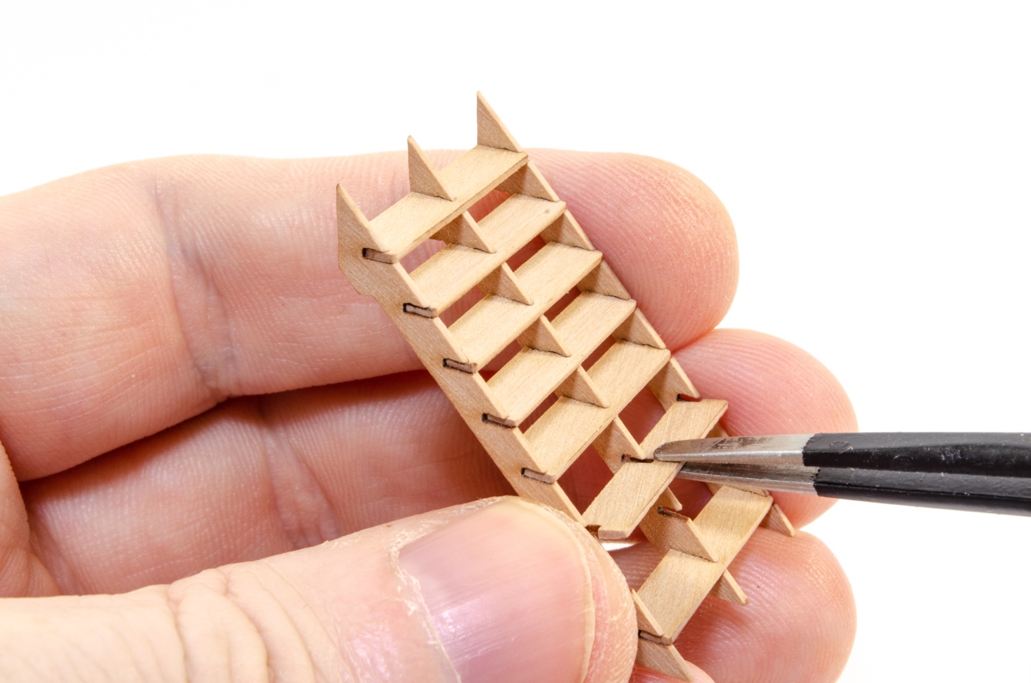
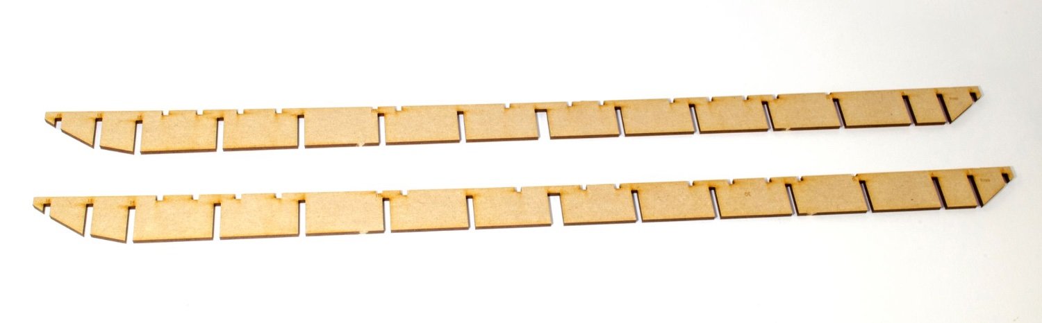
And of course, you'll need some steps down to the dinky orlop deck.

These two beams are now added, again without glue.

These two beams hole them firmly in place and are located with two pegs each, glued into the slots.
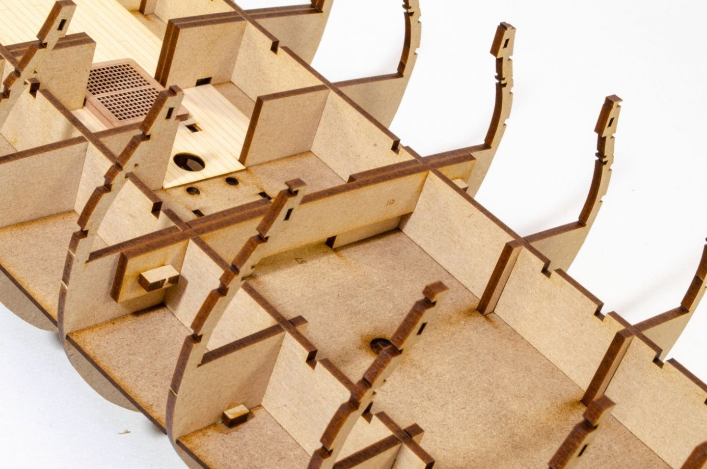
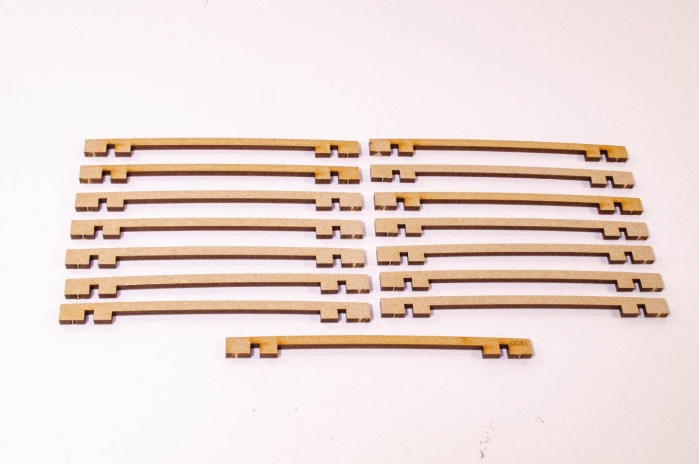
And lastly for this update, a whole raft of deck beams are fitted between those two longitudinal parts.

-
6
-
-
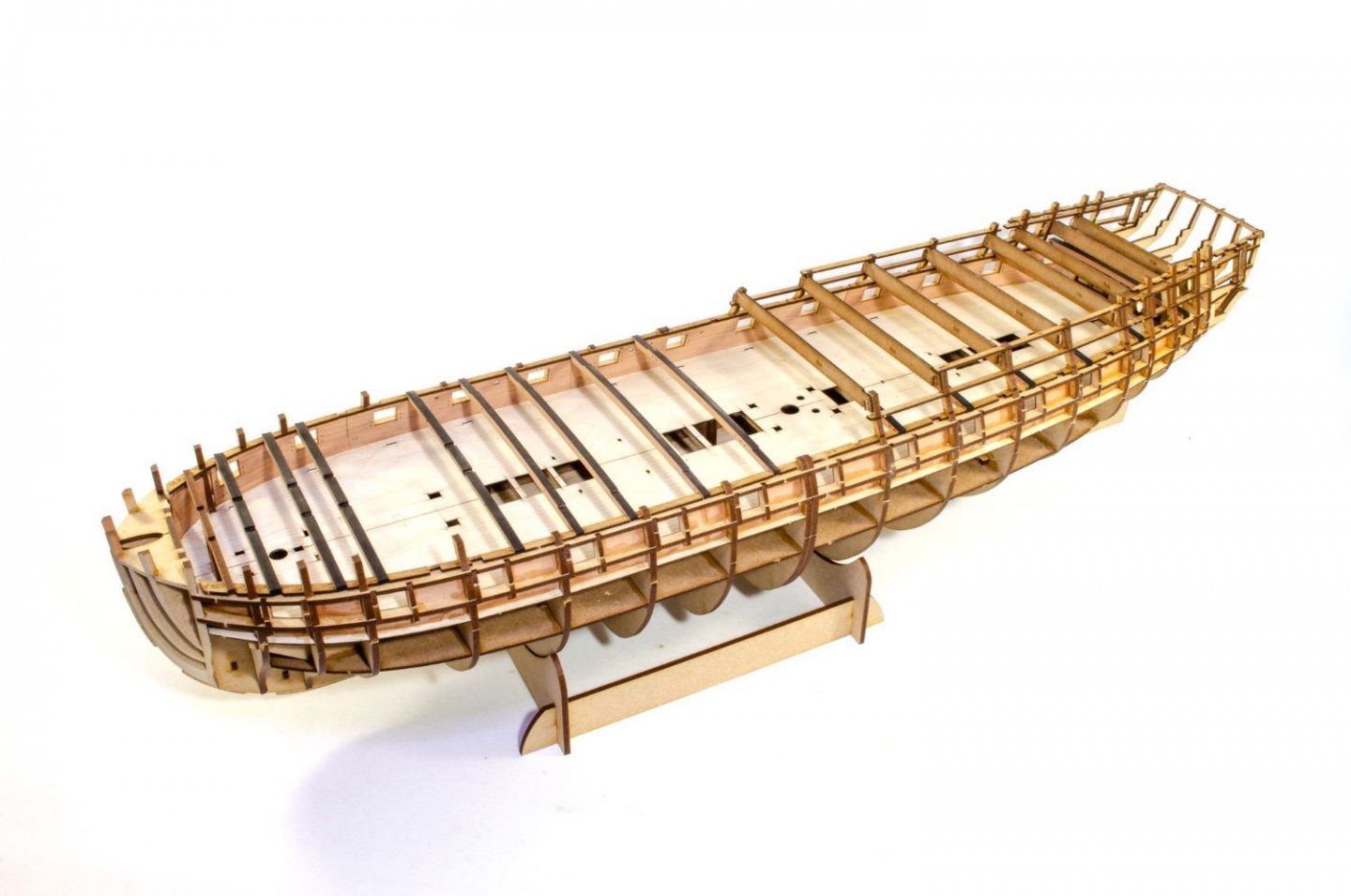
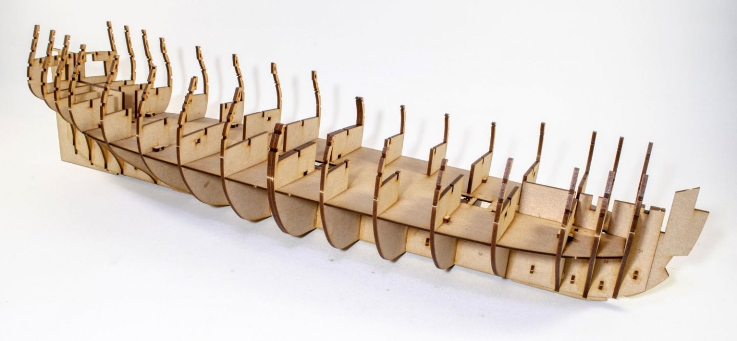
Work has now begun.
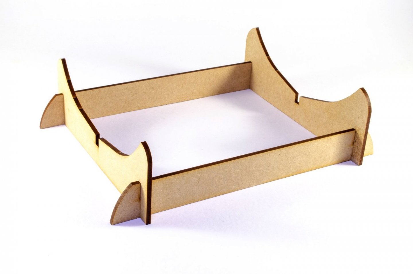
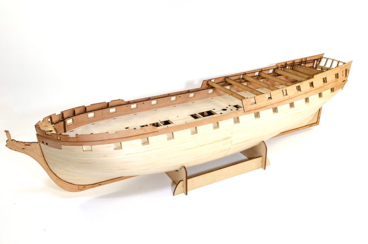
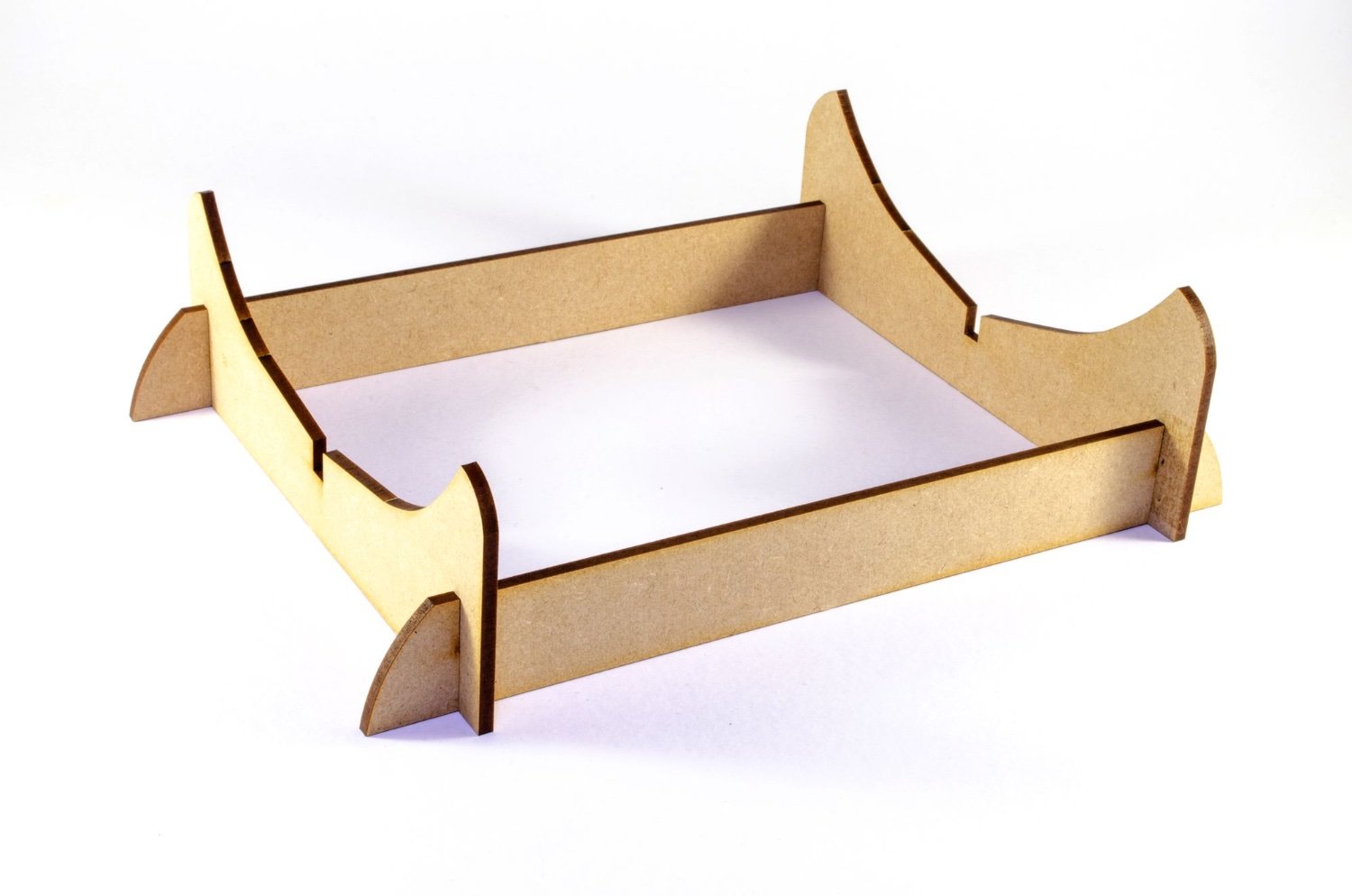
First, the obligatory disposable cradle shot 😃
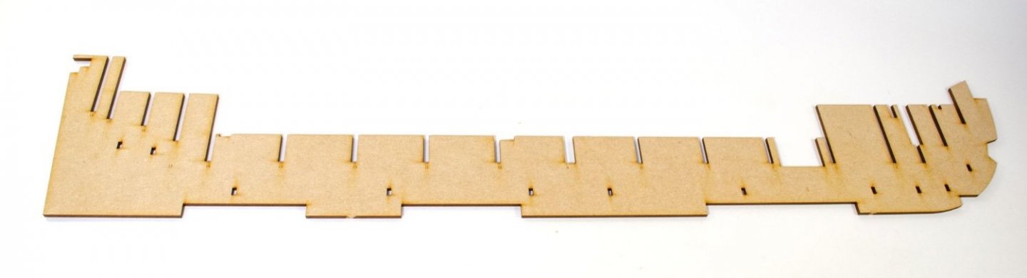
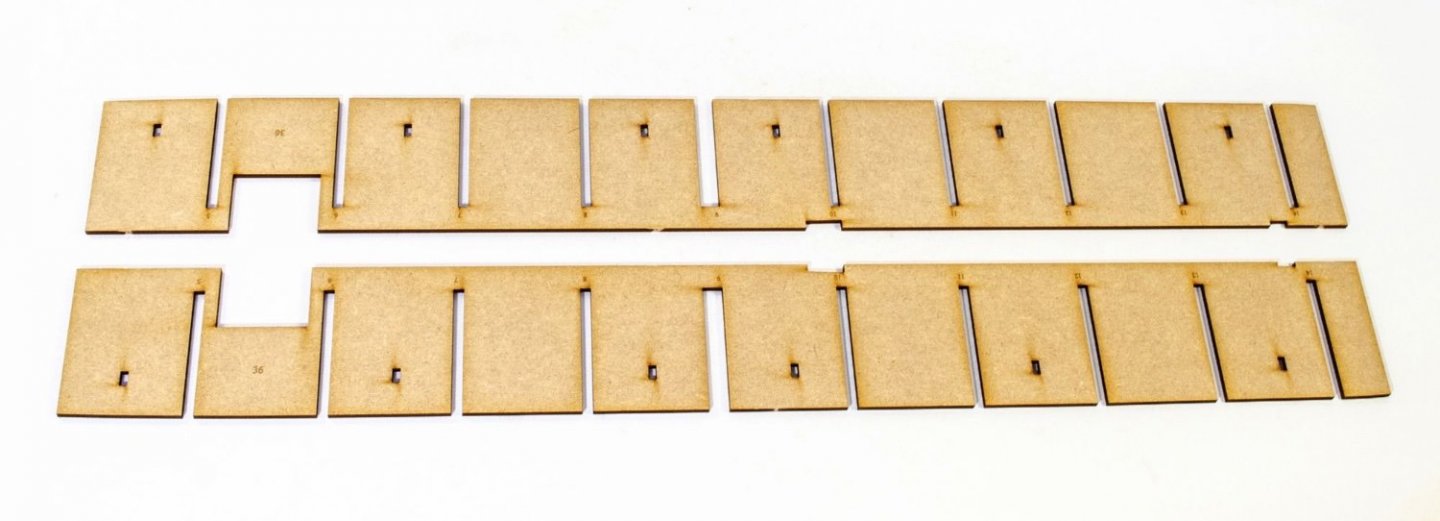
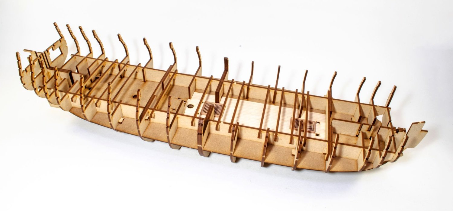
Indy certainly isn't short of bulkheads. There are 18 in total, with #9 midships being a double layer bulkhead. There are no bevel marks on Indy. They simply aren't needed for a kit of this level. Fairing will be an easy task. All bulkheads are 4mm MDF, as is the keel.
The keel slots are numbered too so you get things in the right place.
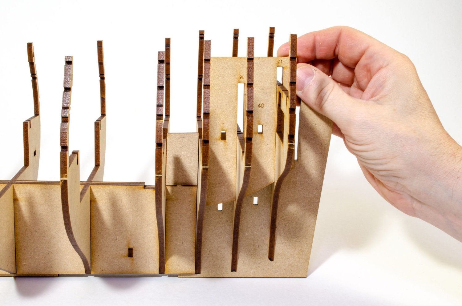
Indy is a strange build in that practically all you see in this update, with the exception of lower deck/orlop detail, can be assembled initially with no glue. All bulkheads you see being added here are put into position as such.
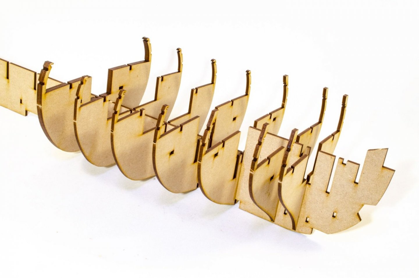
Now this is where the magic happens. Once all bulkheads (apart from #1, #2, #15, #16, #17 and #18 because they aren't needed yet) are slotted into their position, these keel doublers are added, bulking out the keel to 12mm! What these do is to hold the bulkheads in their exact position. while pegs slot through the holes to lock everything into position. Zero glue apart from the pegs themselves.
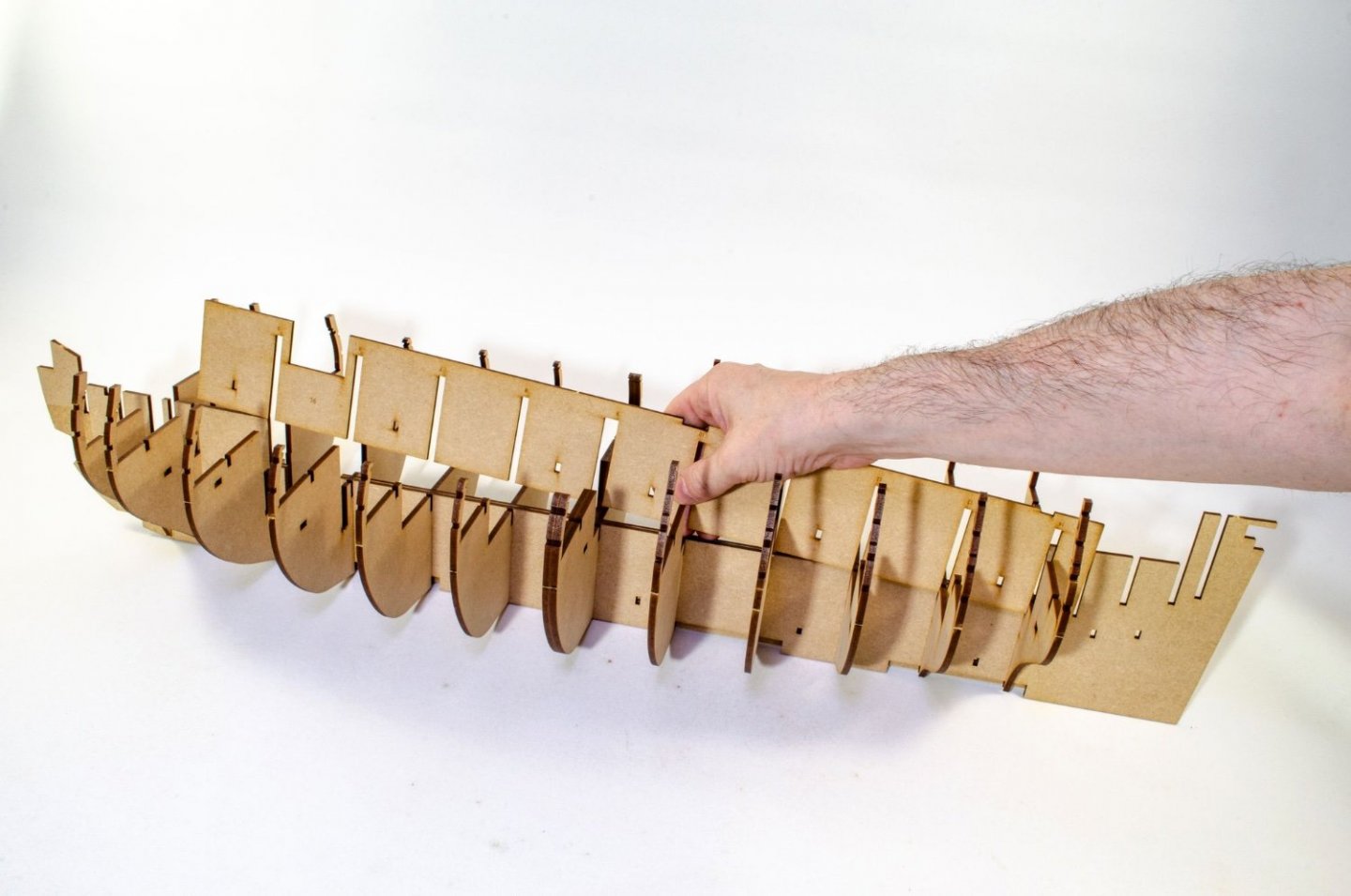
Bulkheads #15, #16 and #17 are now added because the fairing parts will now lock them into position as with the other bulkheads.
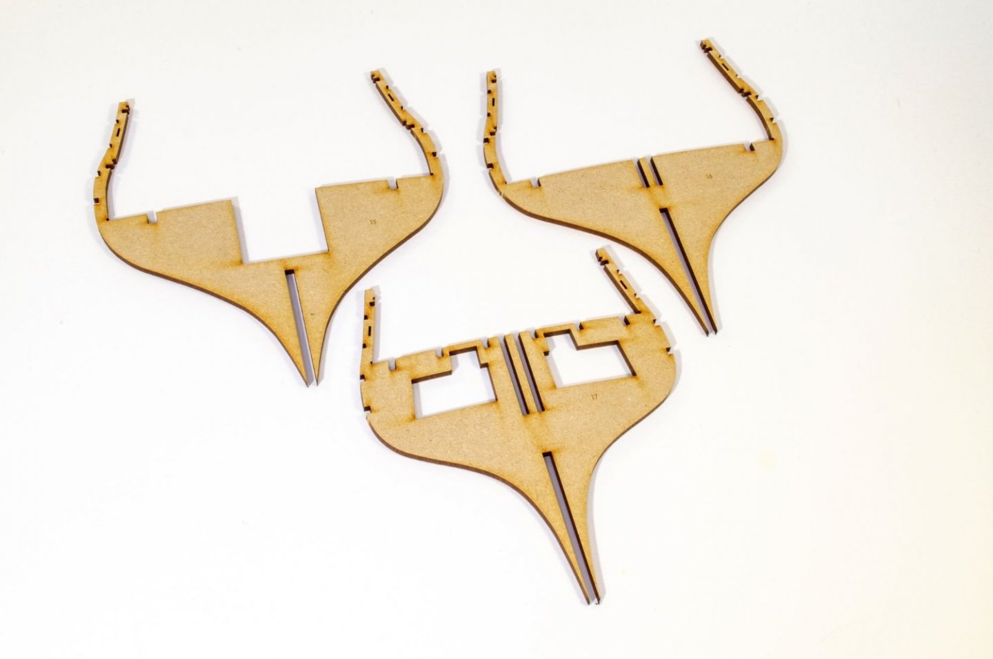

Bulkheads #1 and #2 are now fitted, but NO GLUE at this time. The fairing patterns are now added. You will see these as No.s 37, 38 and 39. Like the others, these are pegged into place.
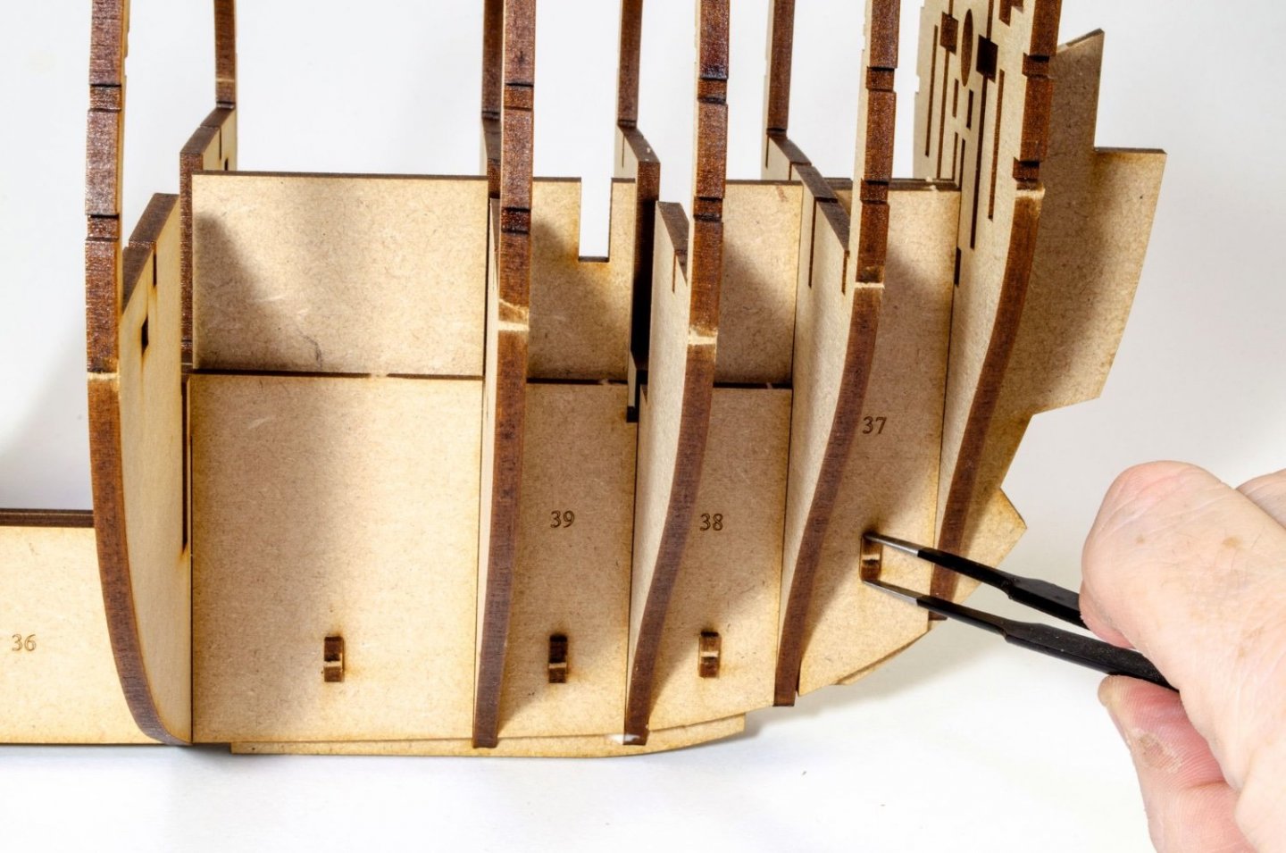
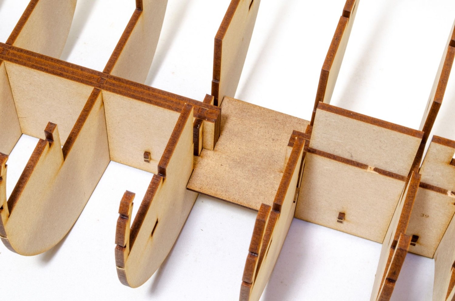
Is there an orlop deck? There certainly is. This is it 😆
Nothing more is needed. In fact, you'll probably not even see this without an endoscope. This part is glued into place.
The 3mm MDF sub deck is now fitted. Care needs to be taken around the bulkhead ears. You should have no problem....just don't go charging in. To fit this, I ran some Titebond down the 12mm wide keel centreline. Nothing here needed to be weighted down or pinned. It fit perfectly with a reassuring push.
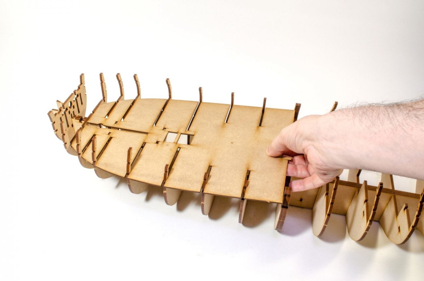
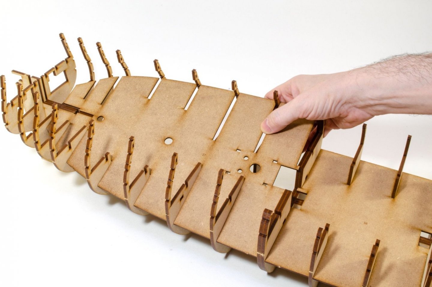
Pegs are now pushed into position which give a further aid to making sure everything is level.
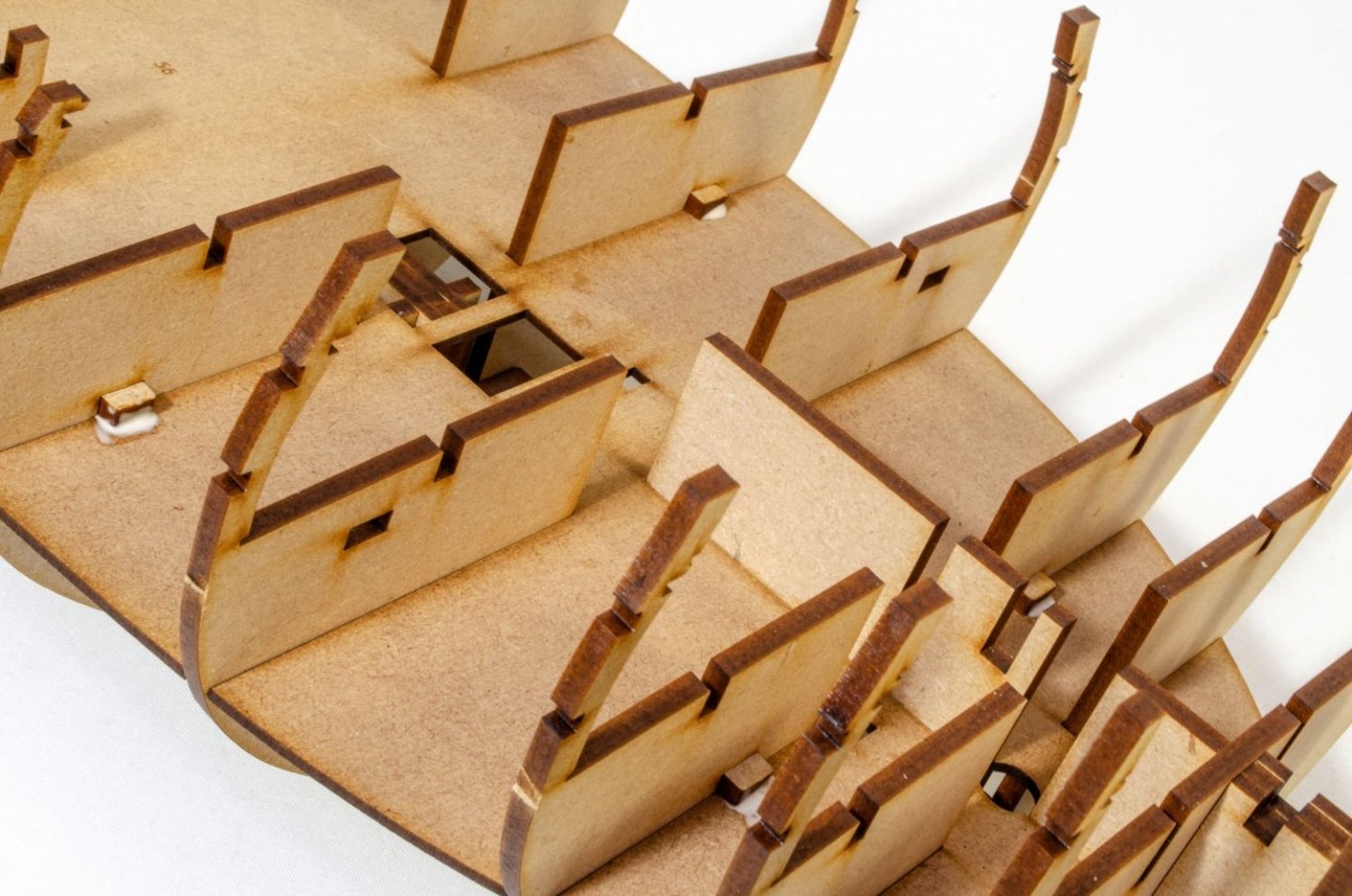
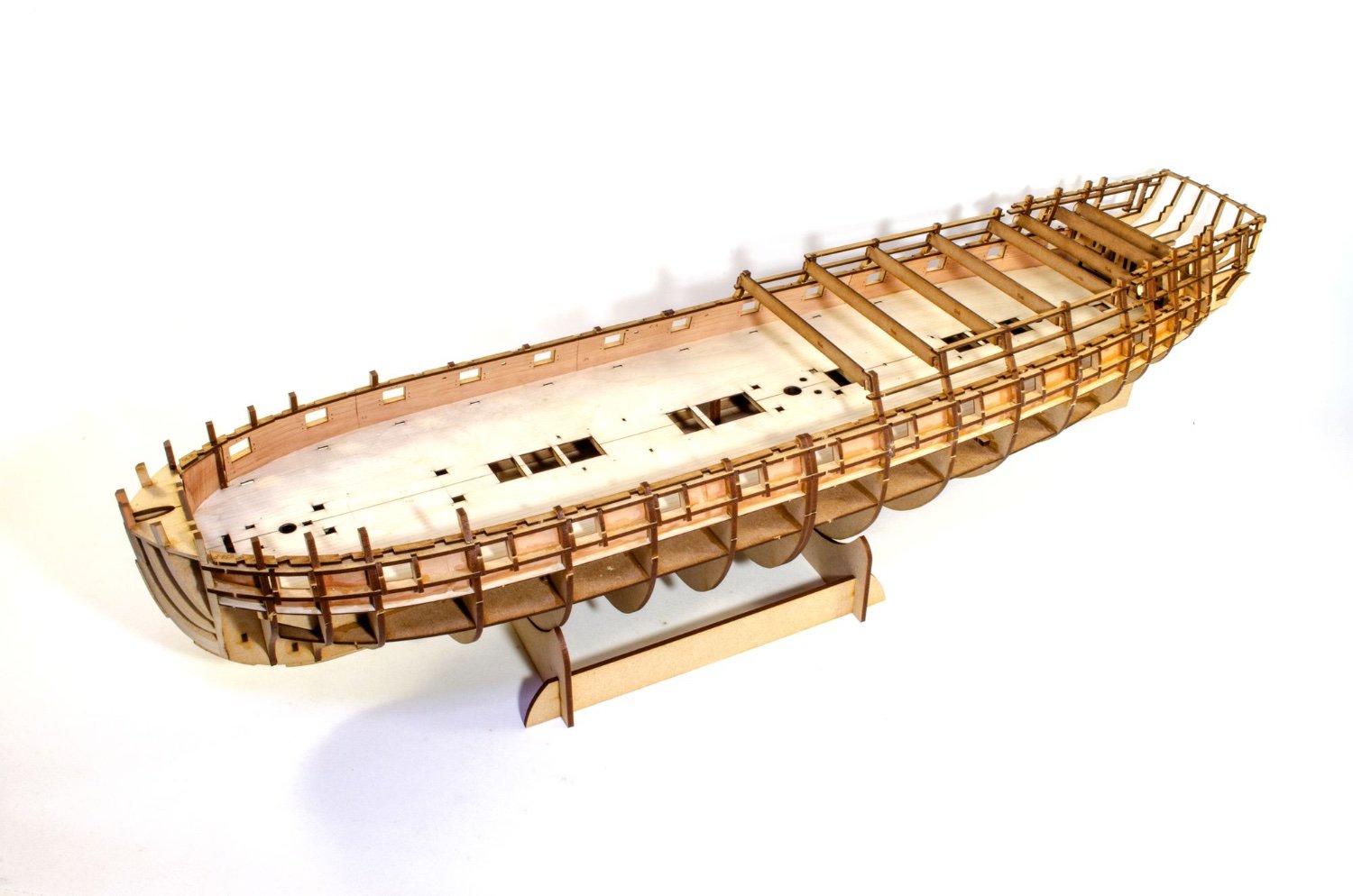
At this stage, things look like this:
-
8
-
-
This photo gives a rough idea of the size of Indefatigable to Amati's 1:64 Victory.
-
5
-
-
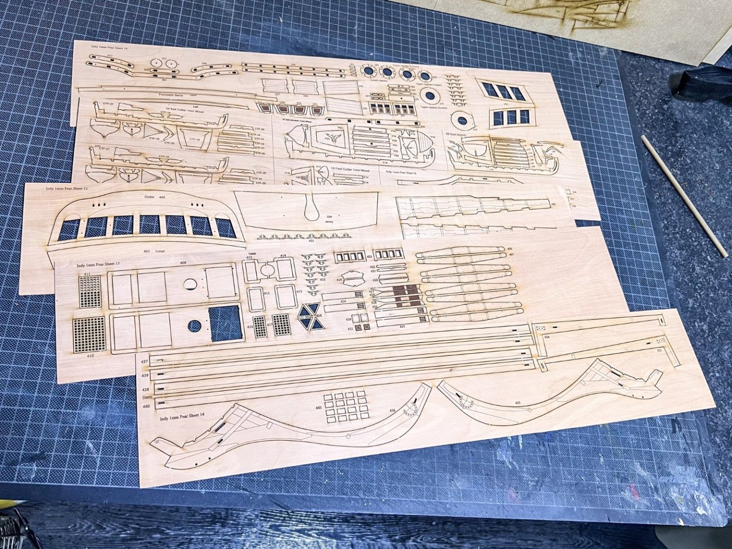
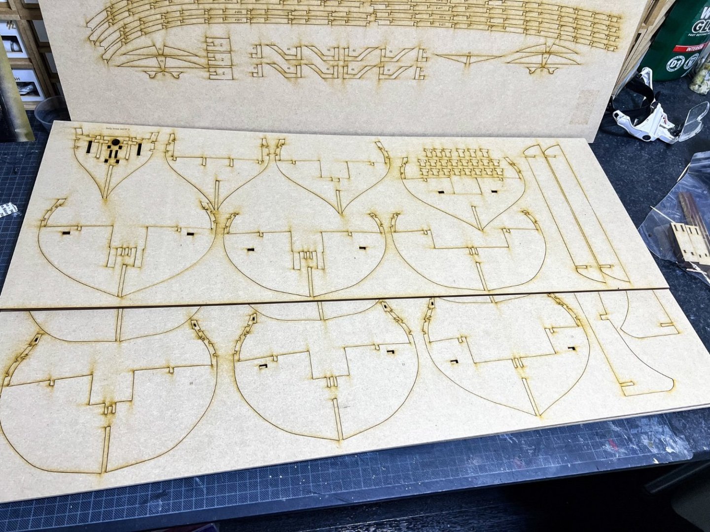
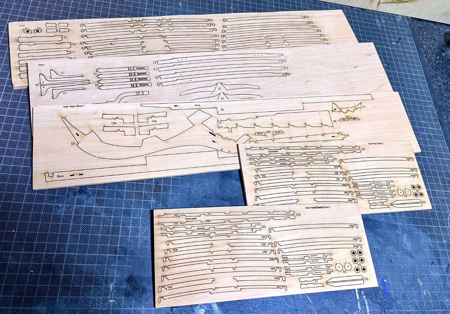
Continued.
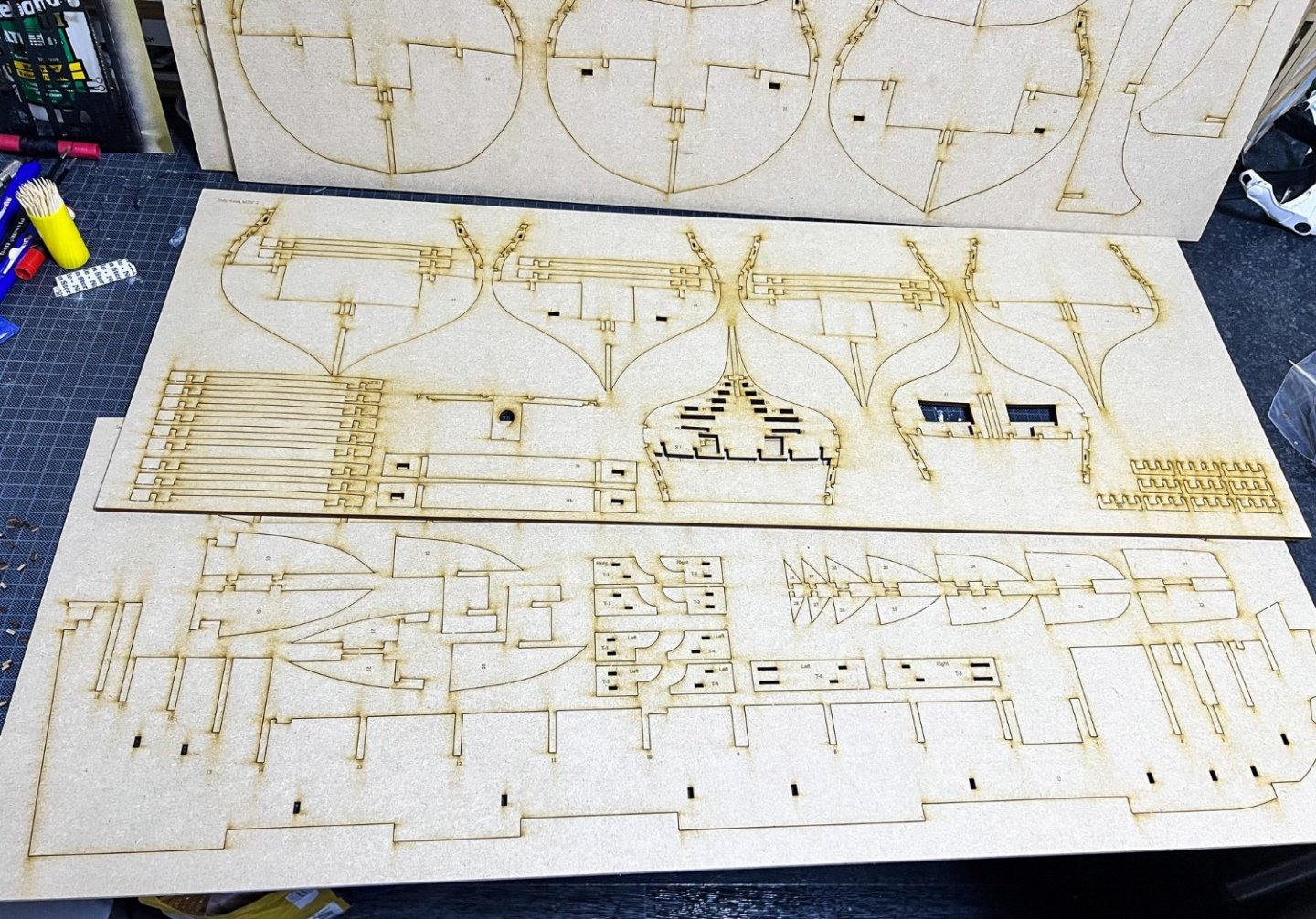
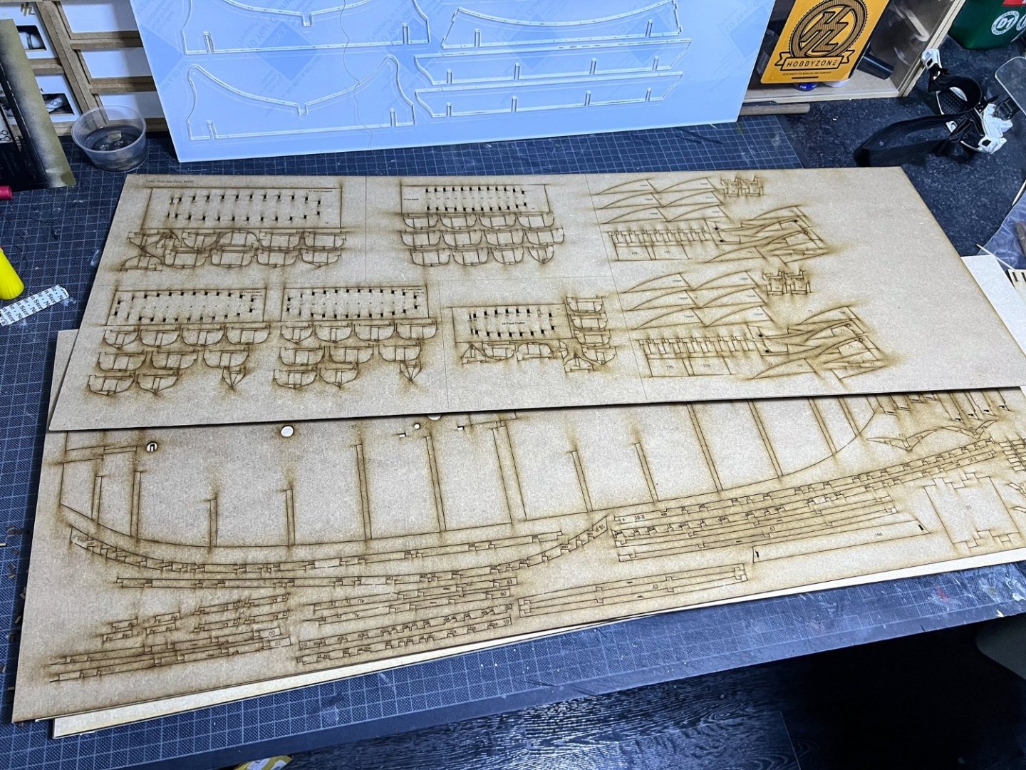
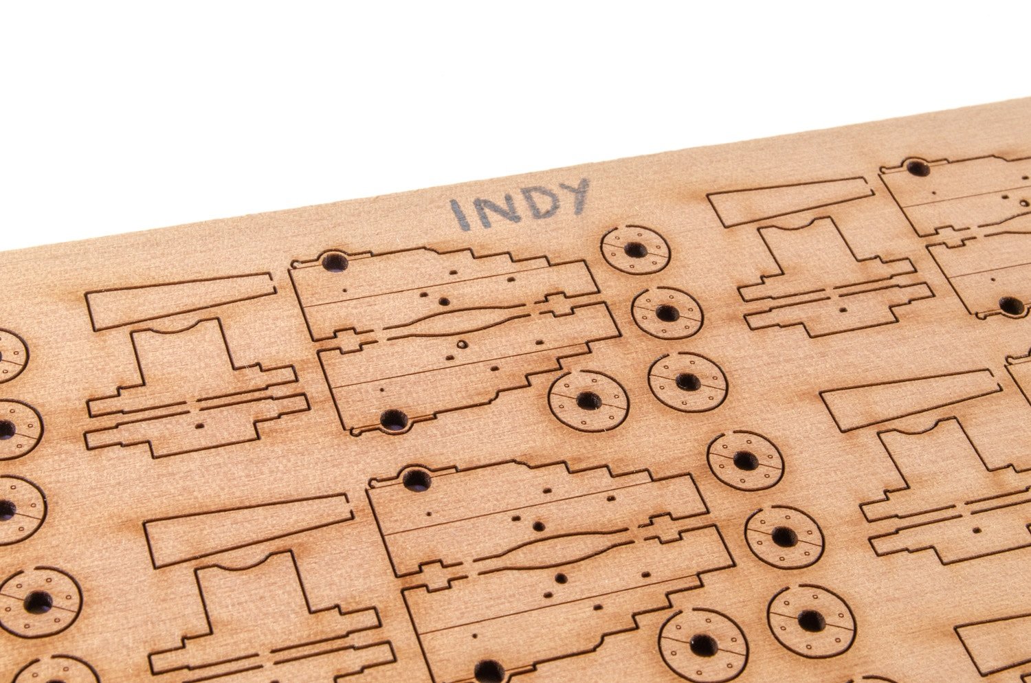
I've grouped most of these photos into thickness of sheet, and there are a lot of various thicknesses with multiple sheets for them. You can see the tabbed gun carts here too. Those tabs are on the forward 'bulkhead', closest to the inner bulwarks.

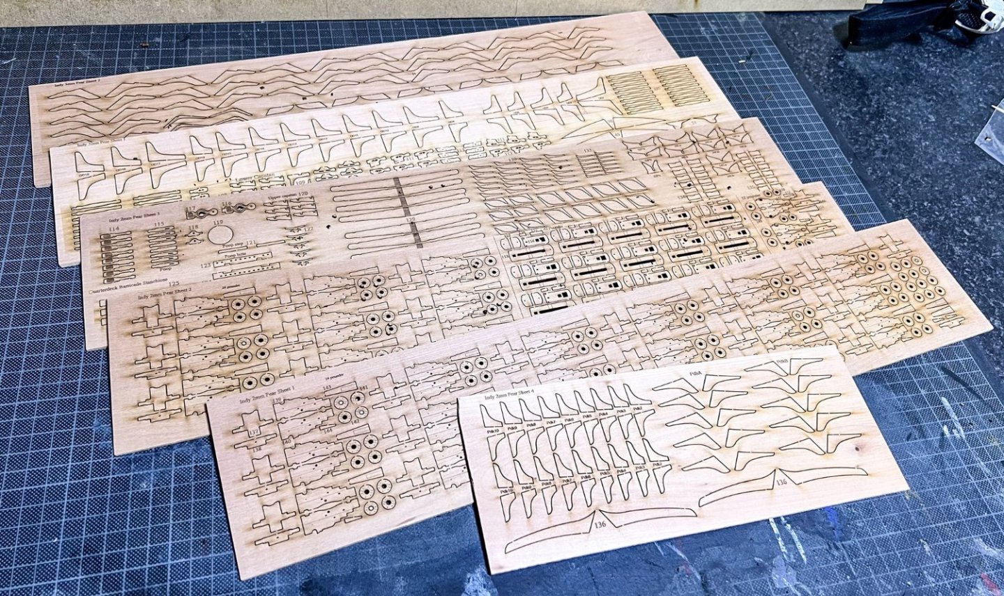
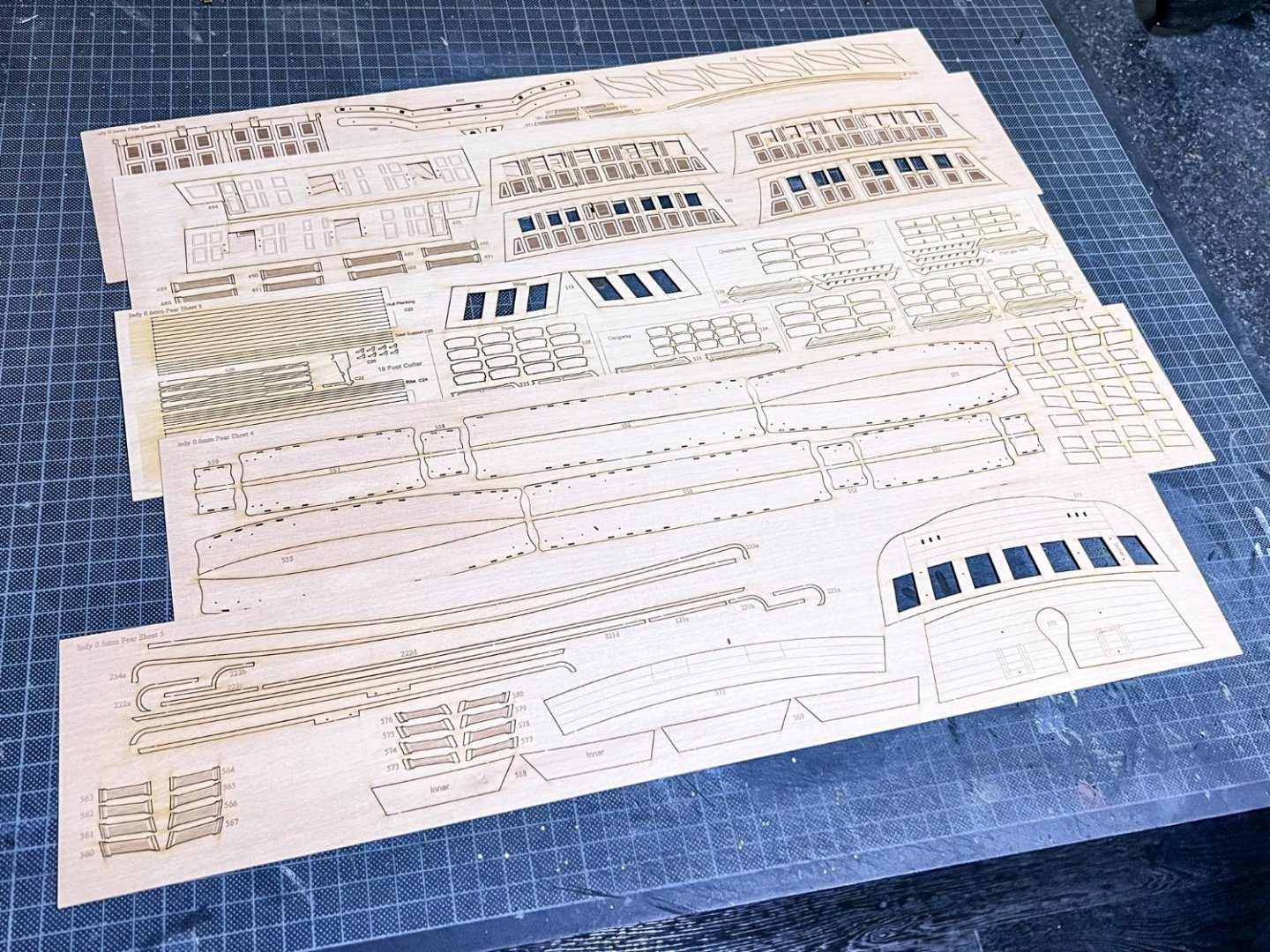
You're going to have to make FIVE ship's boats for this one!
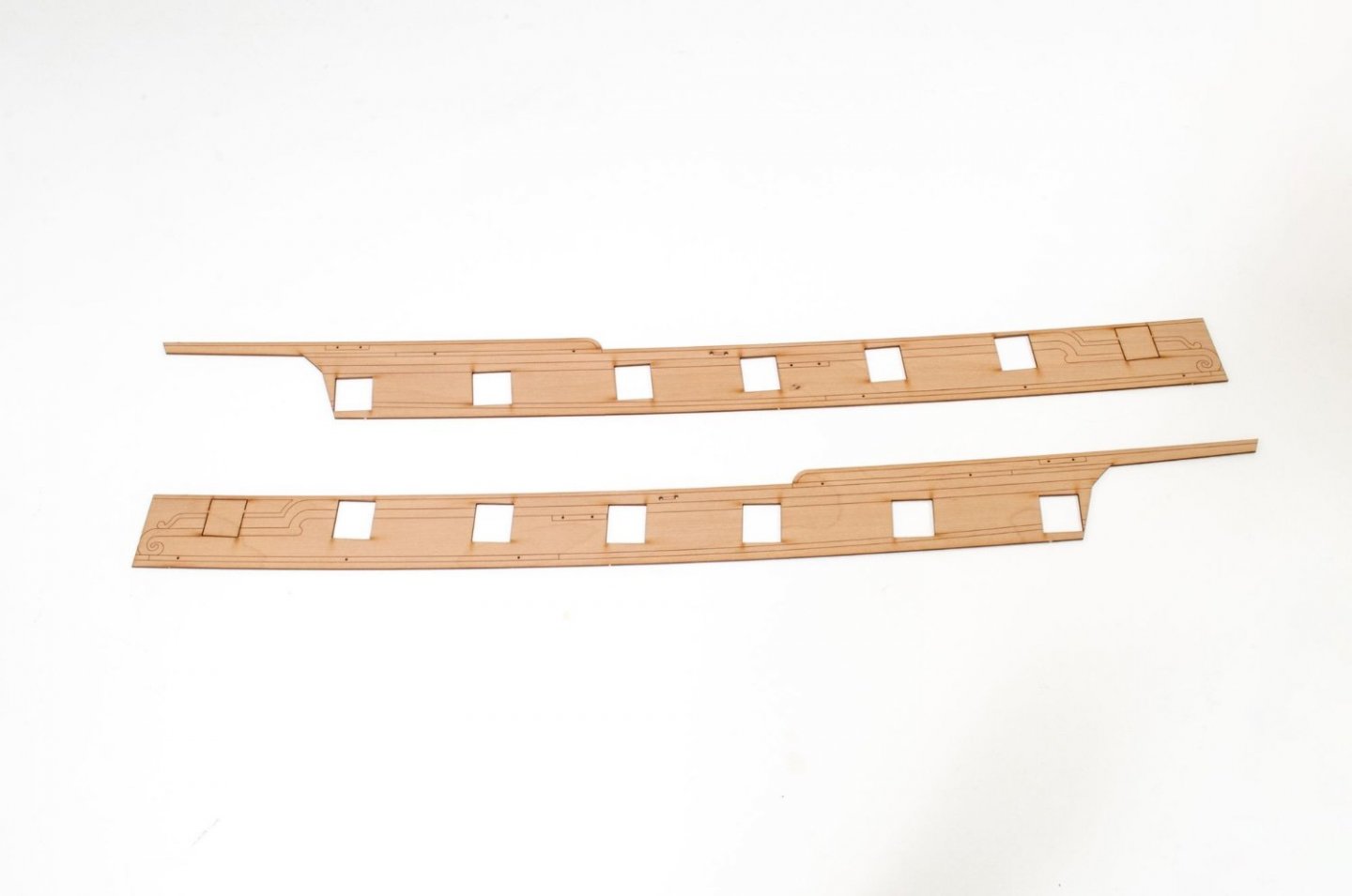
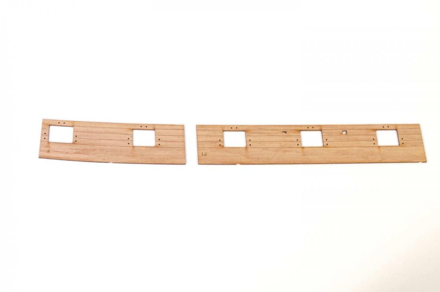
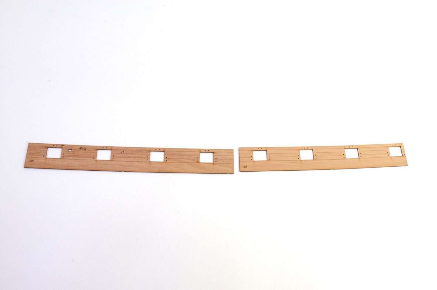
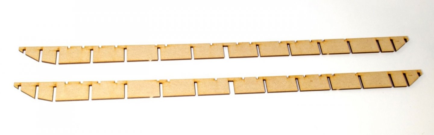
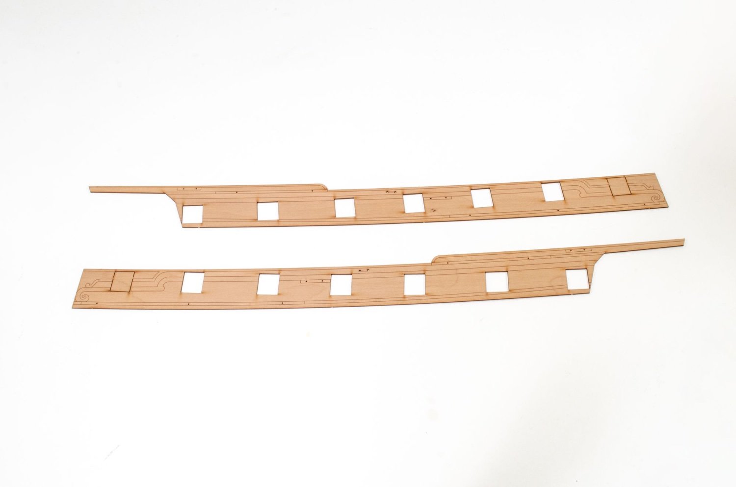
Inner bulwarks are split into three sections to cover the entire length. There will also be doorways from the cabin into the quarter galleries.
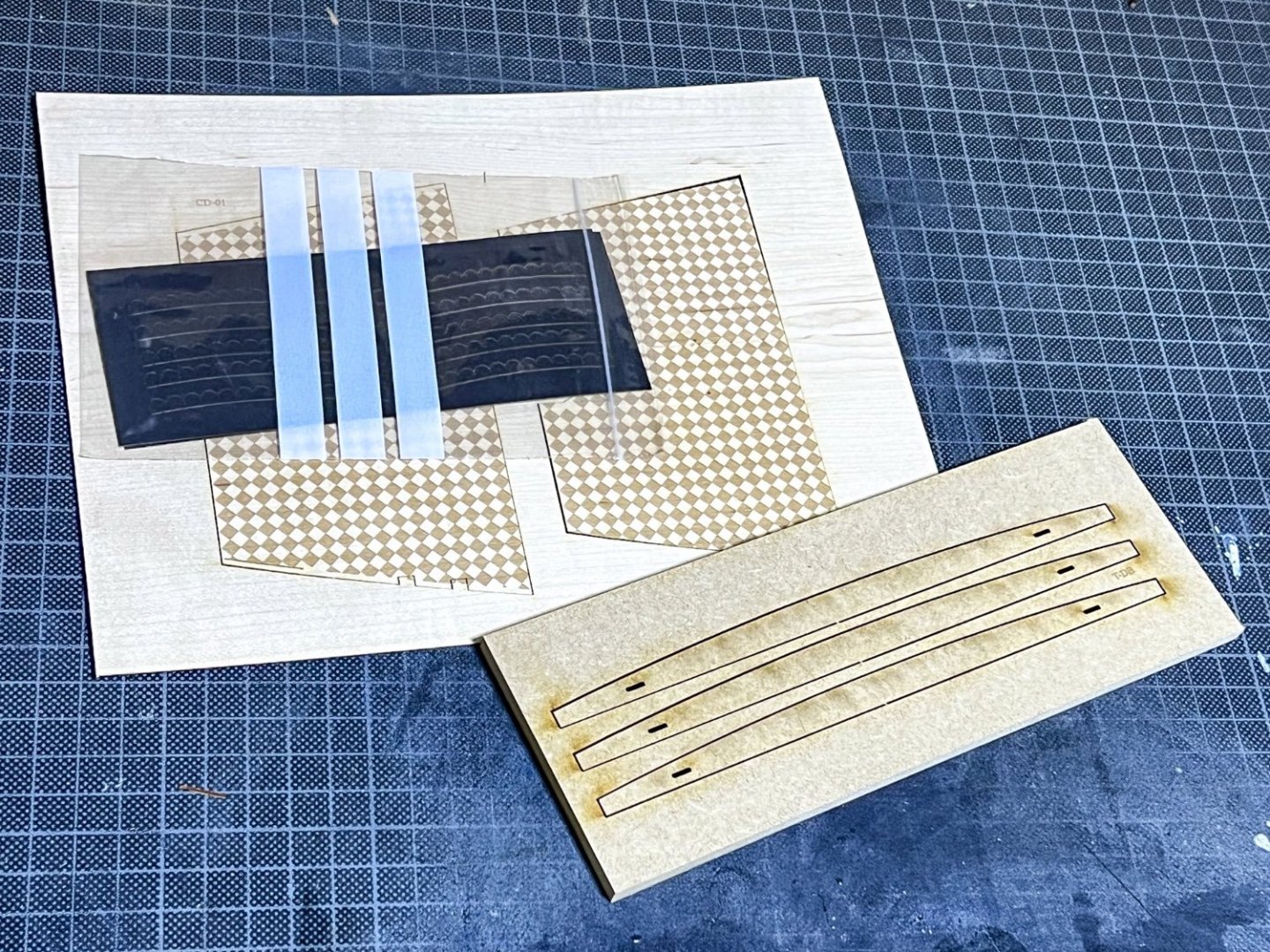
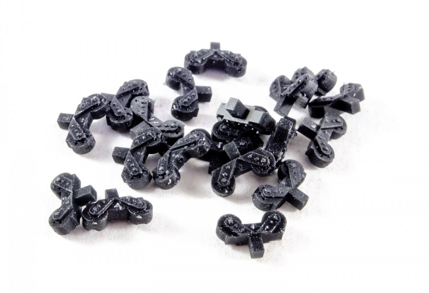
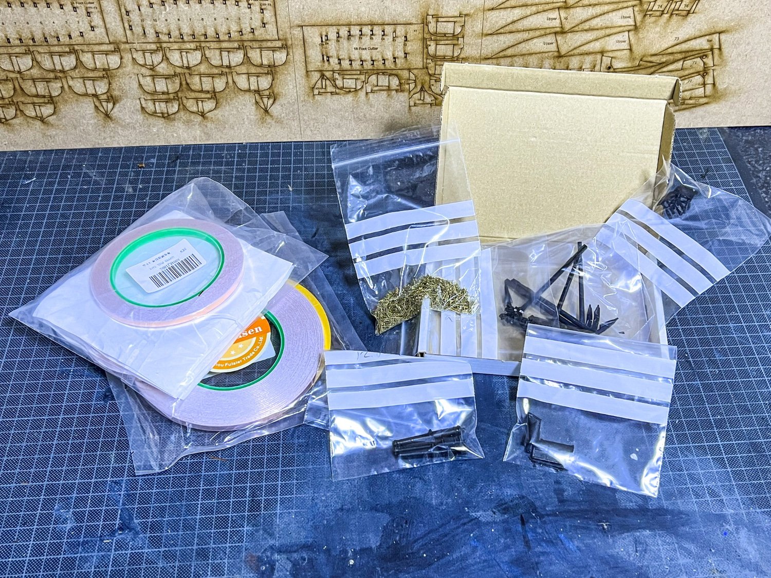
") 3D printed stuff, like belfry, anchors etc. and I do see some copper tape there too.
3D printed stuff, like belfry, anchors etc. and I do see some copper tape there too.
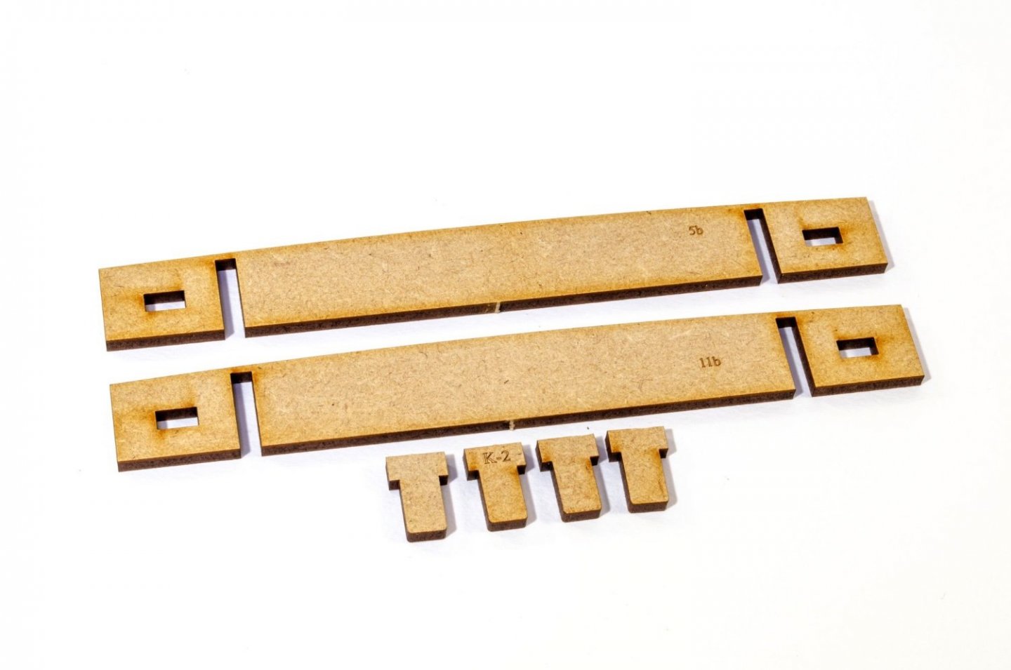
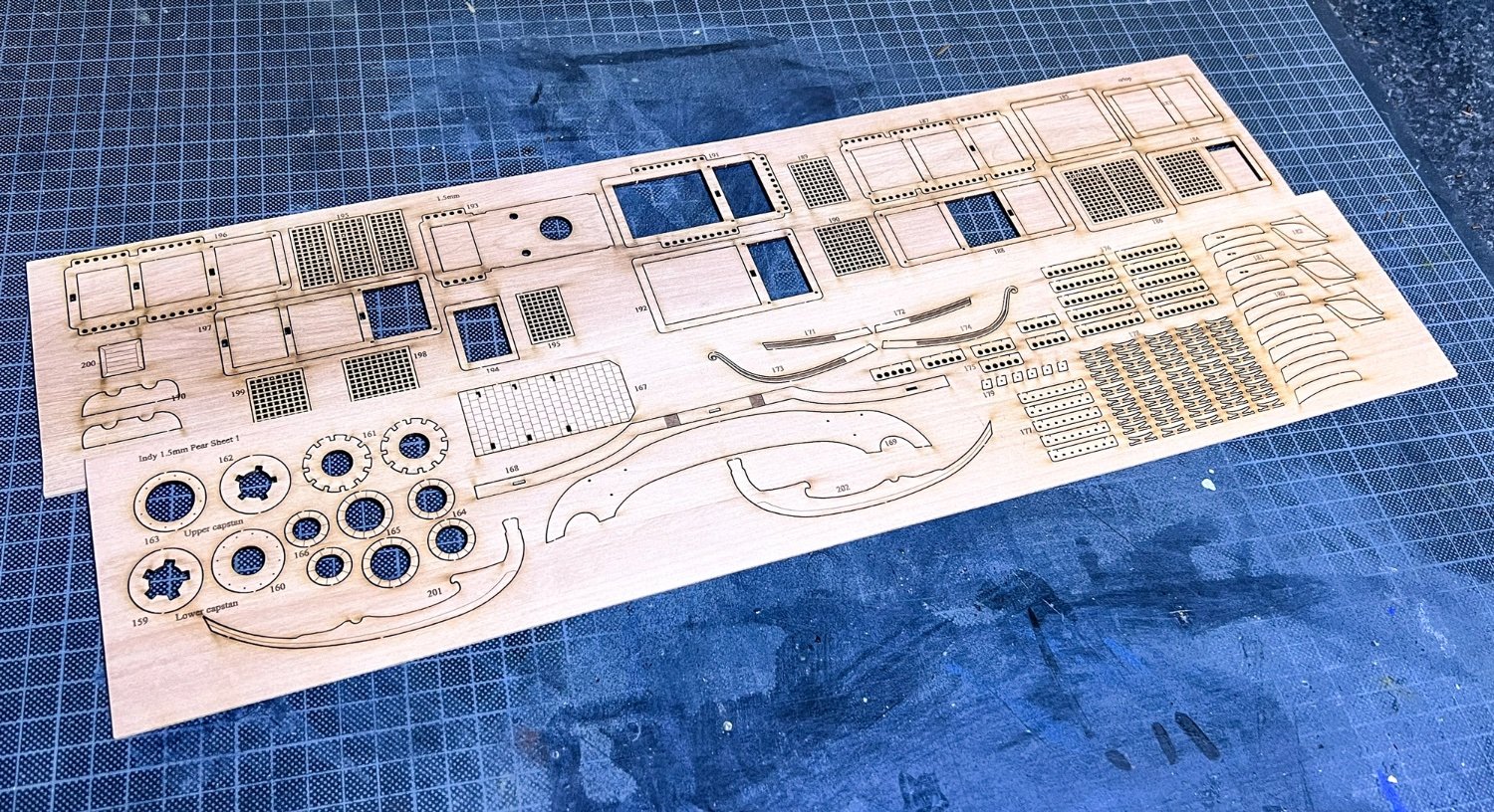
Quirks of prototyping. Various cabin floor sections.
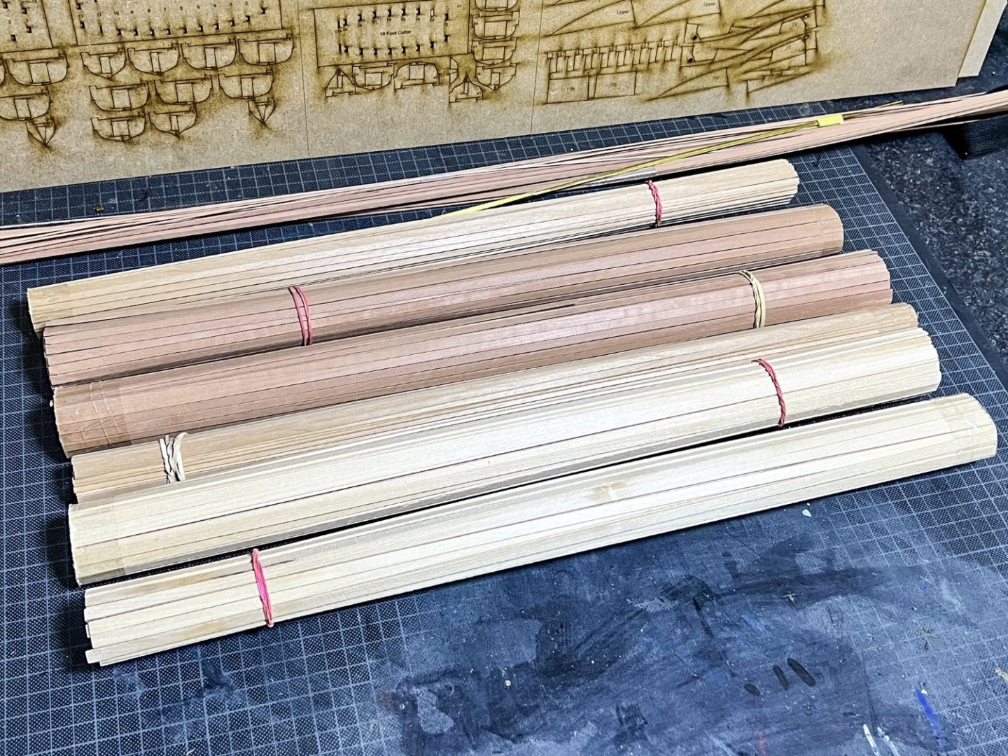
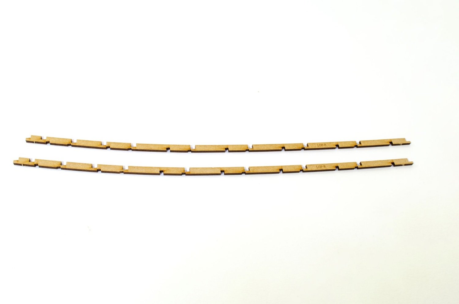
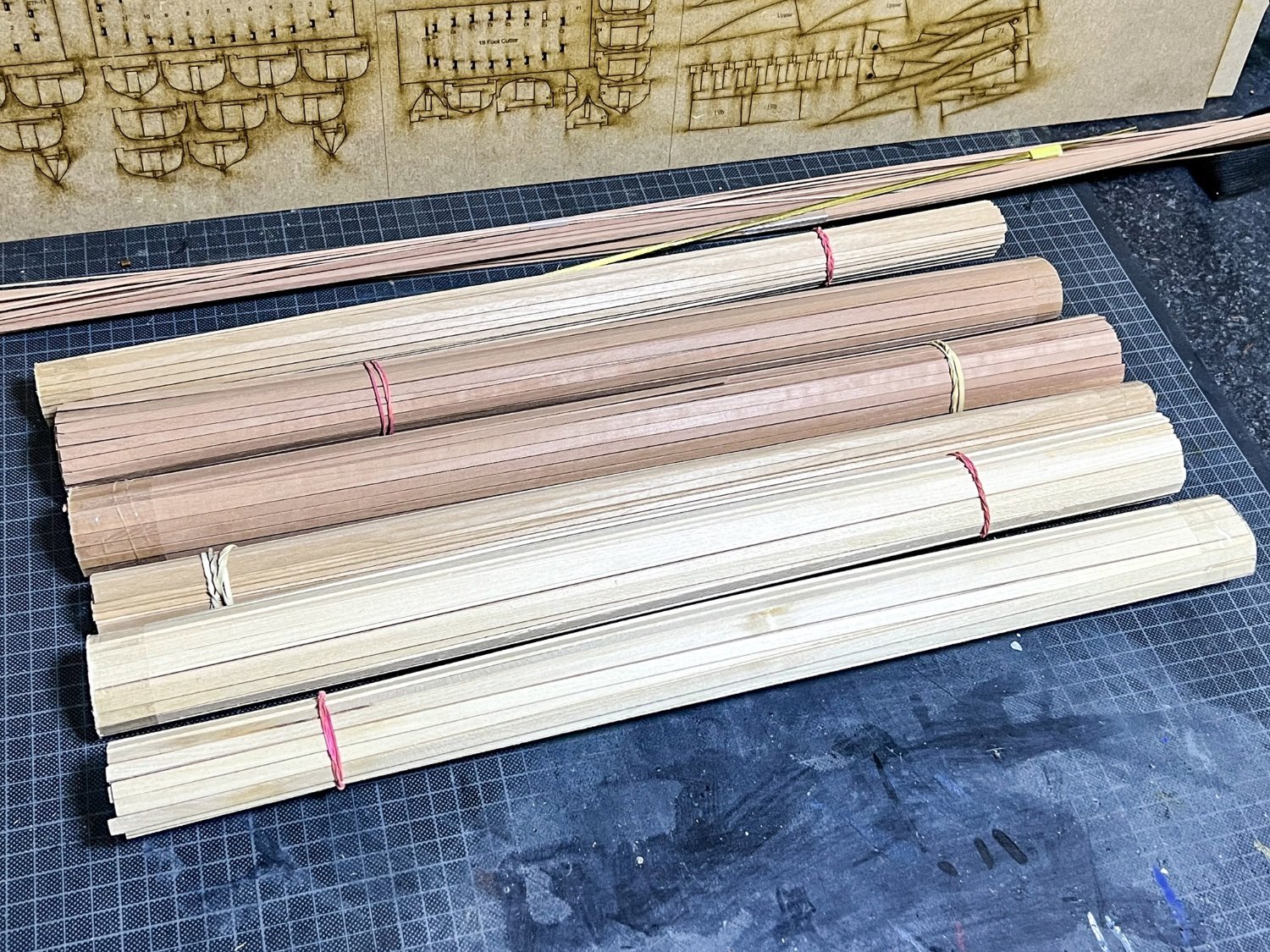
LOTS of strip too.
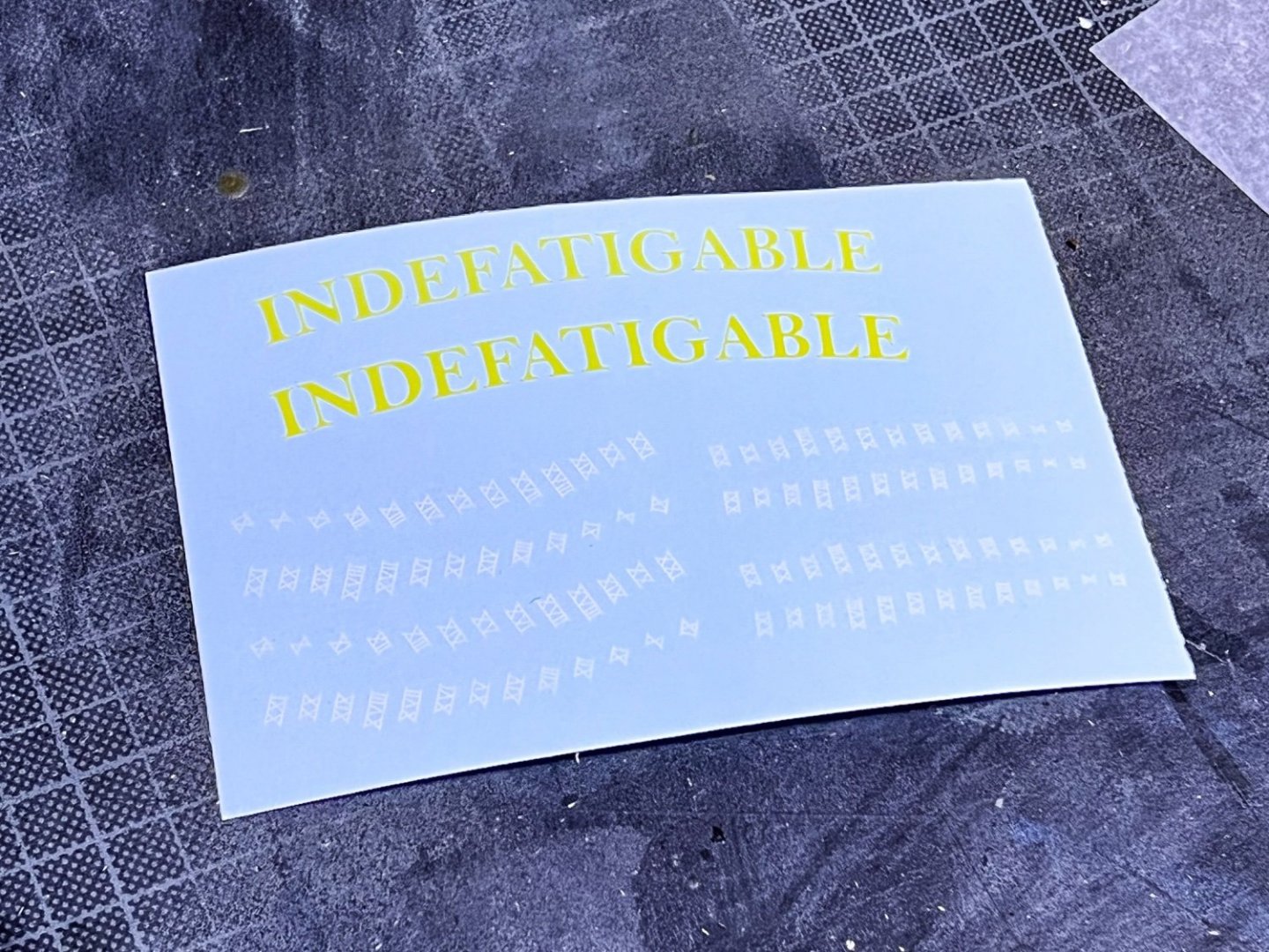
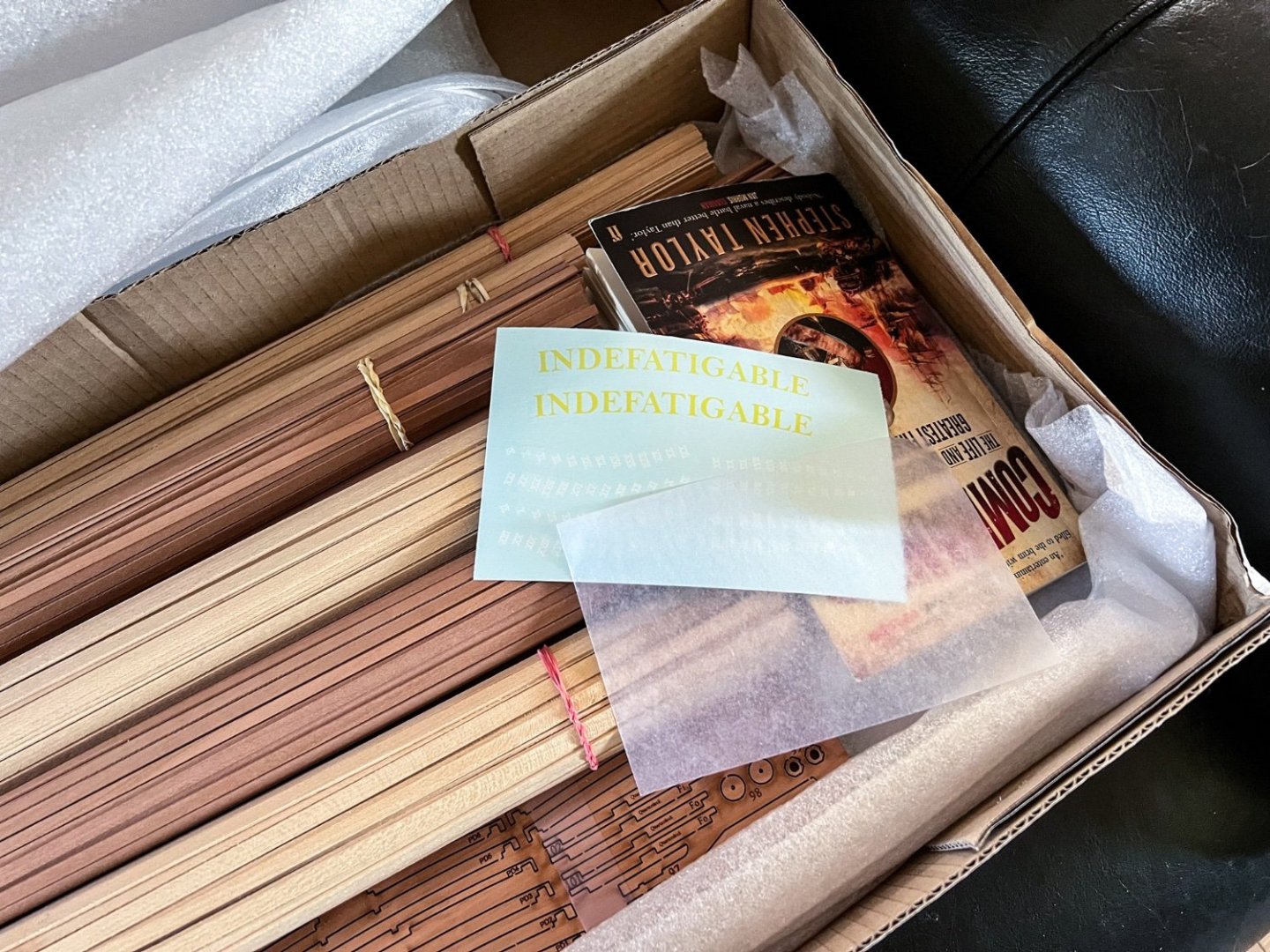
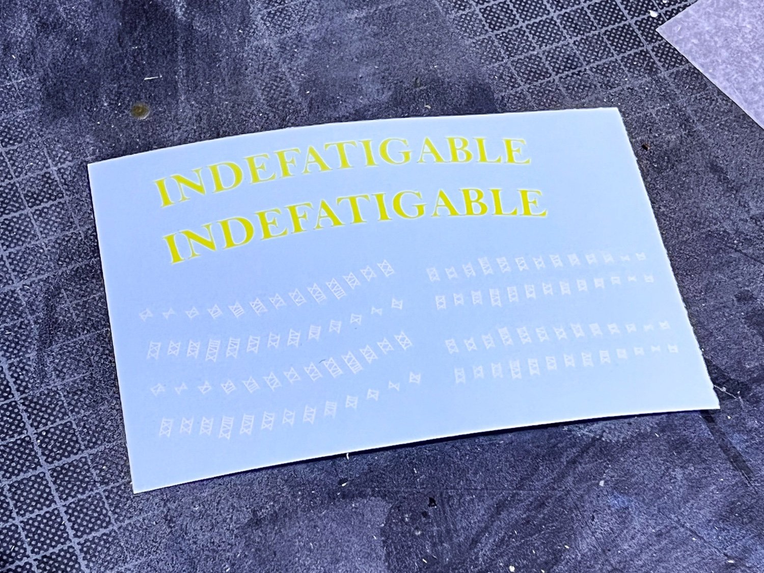
Decals for name and depth markings. Also, there is no white edge on that text. It's merely the light catching the ink edging! I have checked.
-
5
-
-
Time for a quick update. This will be the last one before work starts very shortly.
I'm making this update over TWO posts due to number of pics. These are just camera photos and won't represent anything you see in the manual.
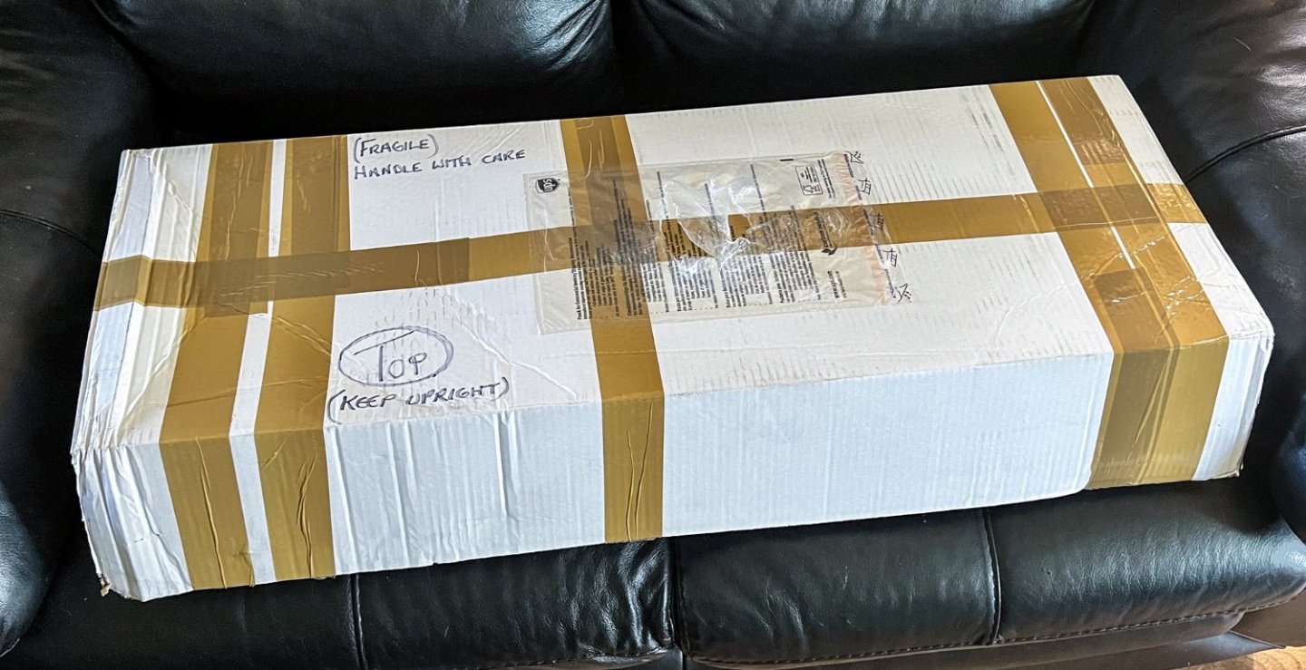
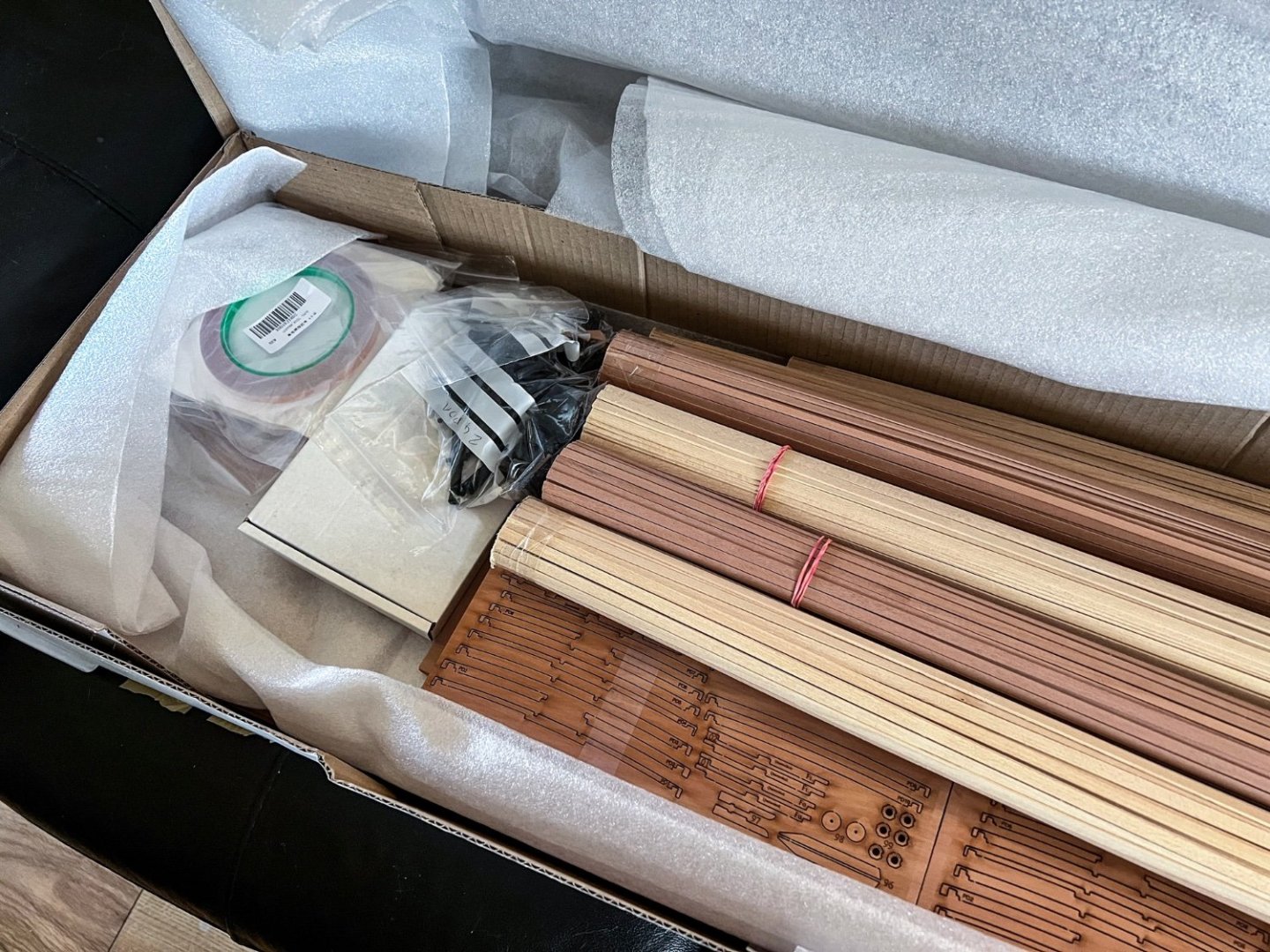
Indy turned up with UPS this morning, and the box is large and heavy. In fact, the box isn't large enough yet as the masting, rigging, manual and plans also need to be included, as well as PE etc. The box was packed out as it was. This one took up two seats on my sofa.
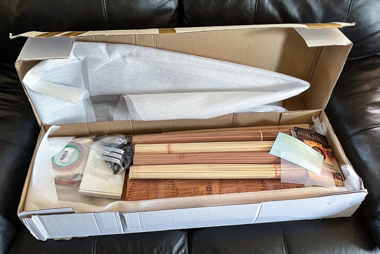
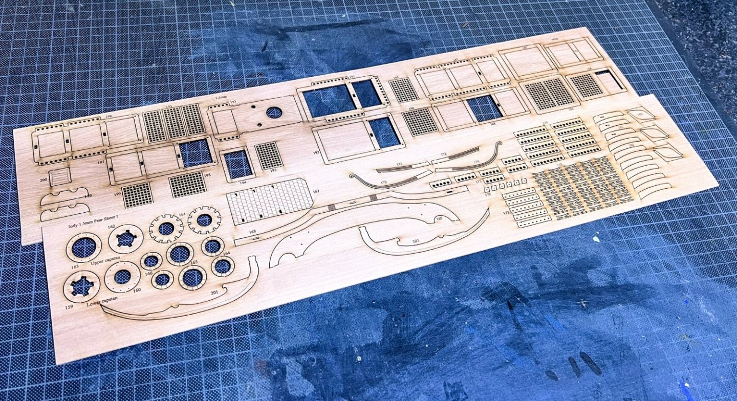
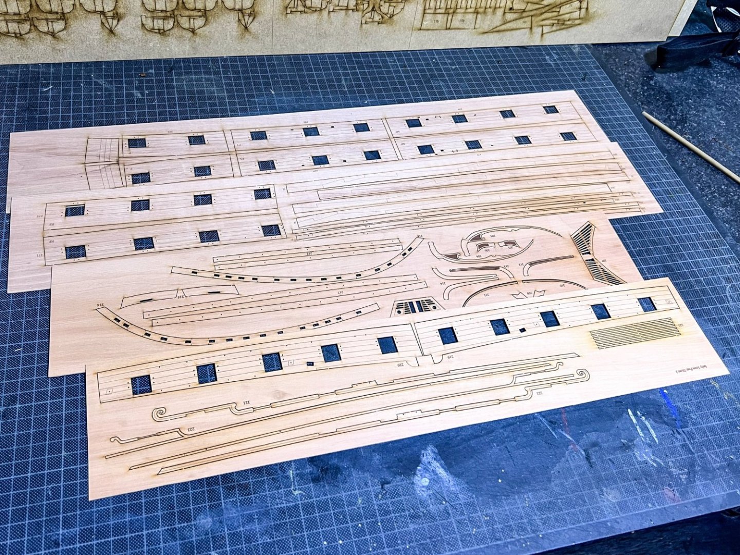
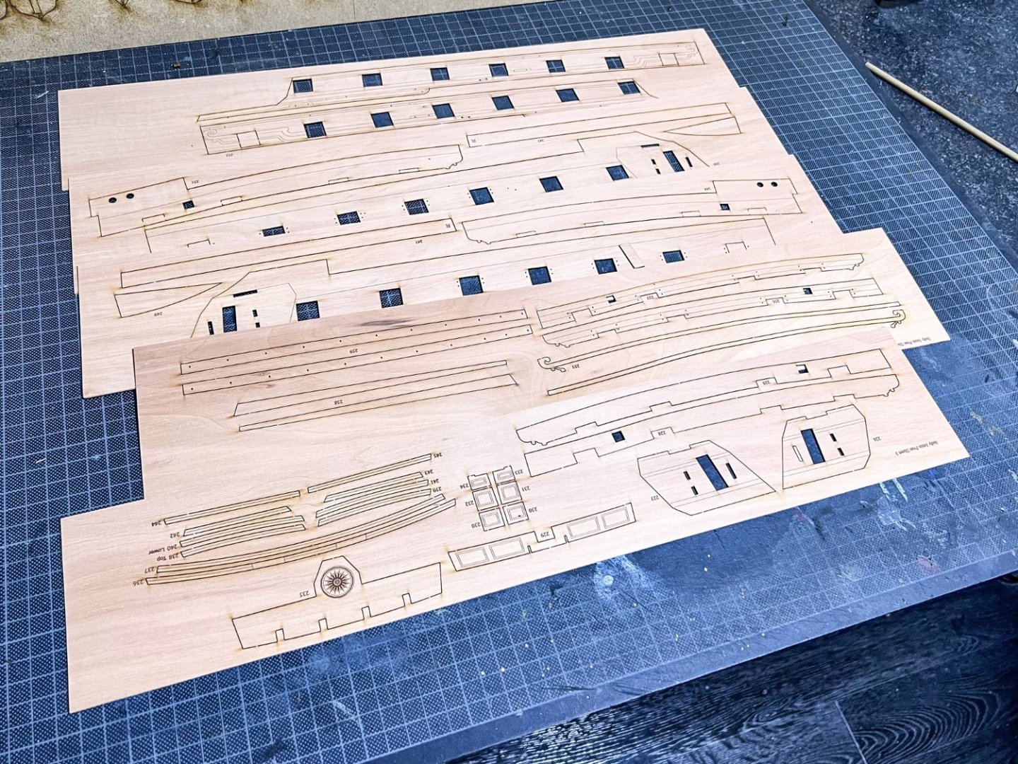
Take a look through and you'll notice some little things here and there. One of those is that the main gun deck carriages are tabbed so they slot into the deck and can't be knocked free later in the build. This is only an optional feature as the modeller can, if they wish, plank over the tab slots and remove the tab from the carriage. That would be up to the individual but this is a perfectly good solution that will be invisible when implemented. If also means the guns will be perfectly spaced too and the barrels therefore evenly protrude from the hull. Those barrels will also be fitted after the hull is painted, so attaching them later won't dislodge a gun cart.

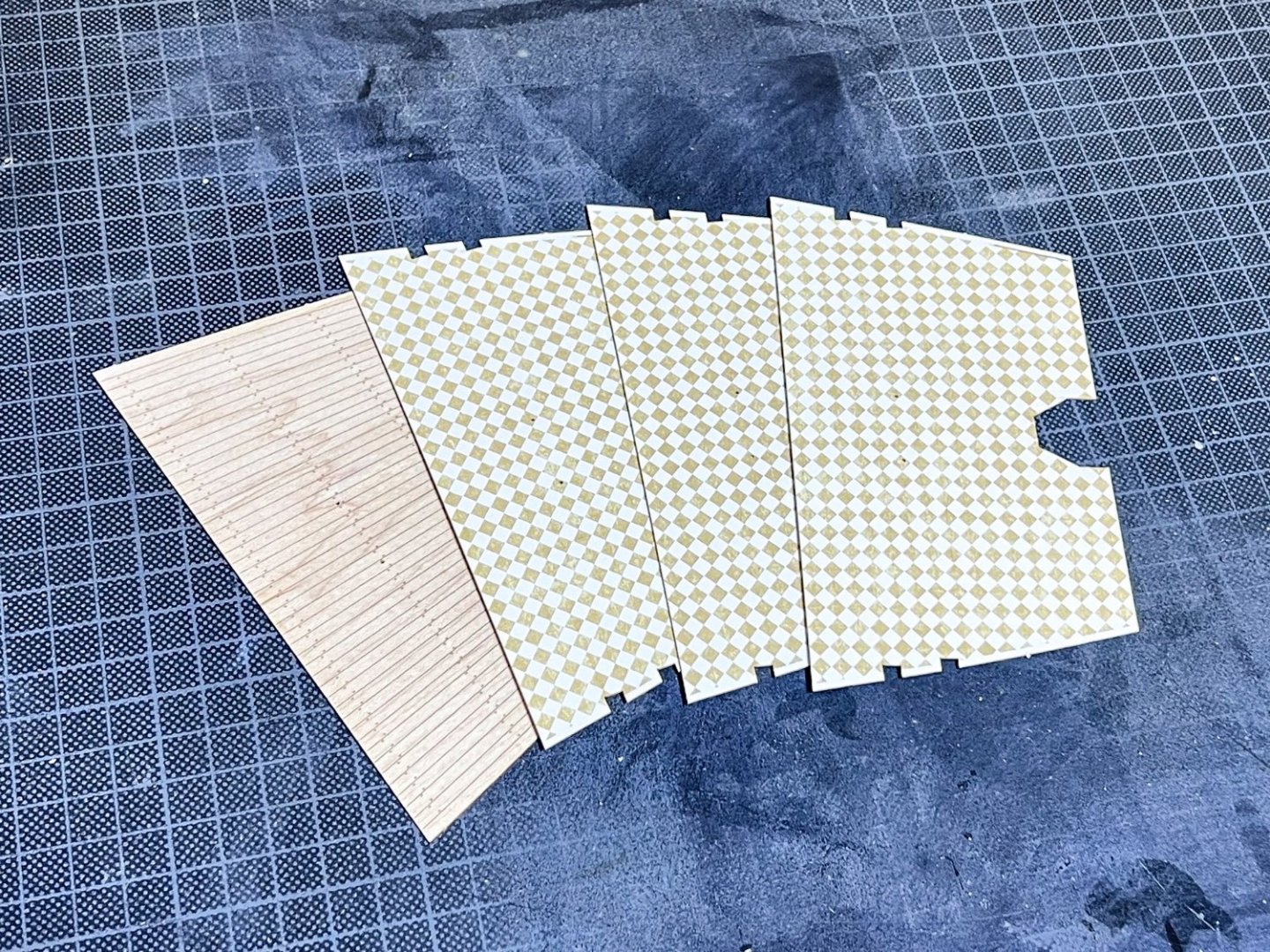
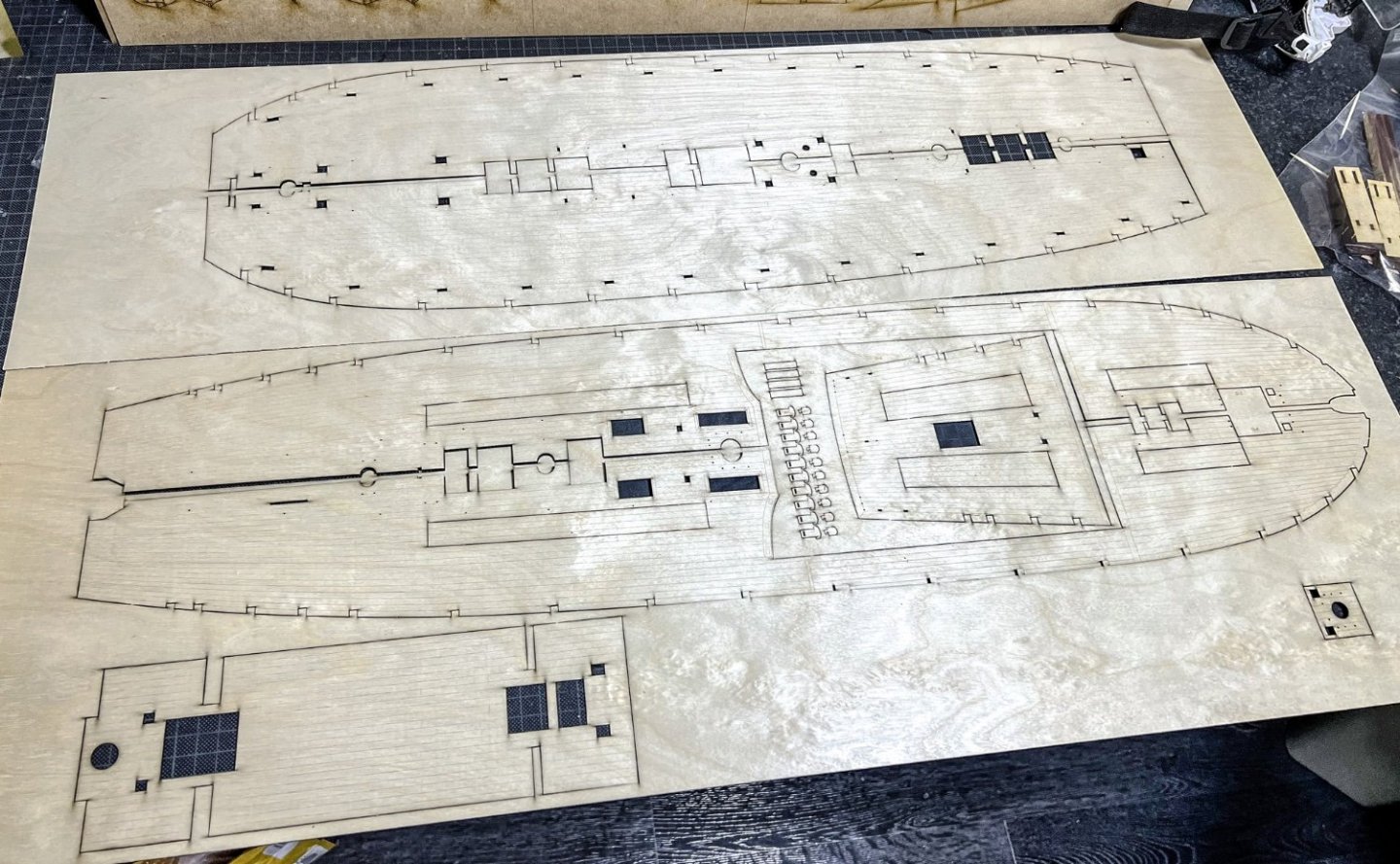
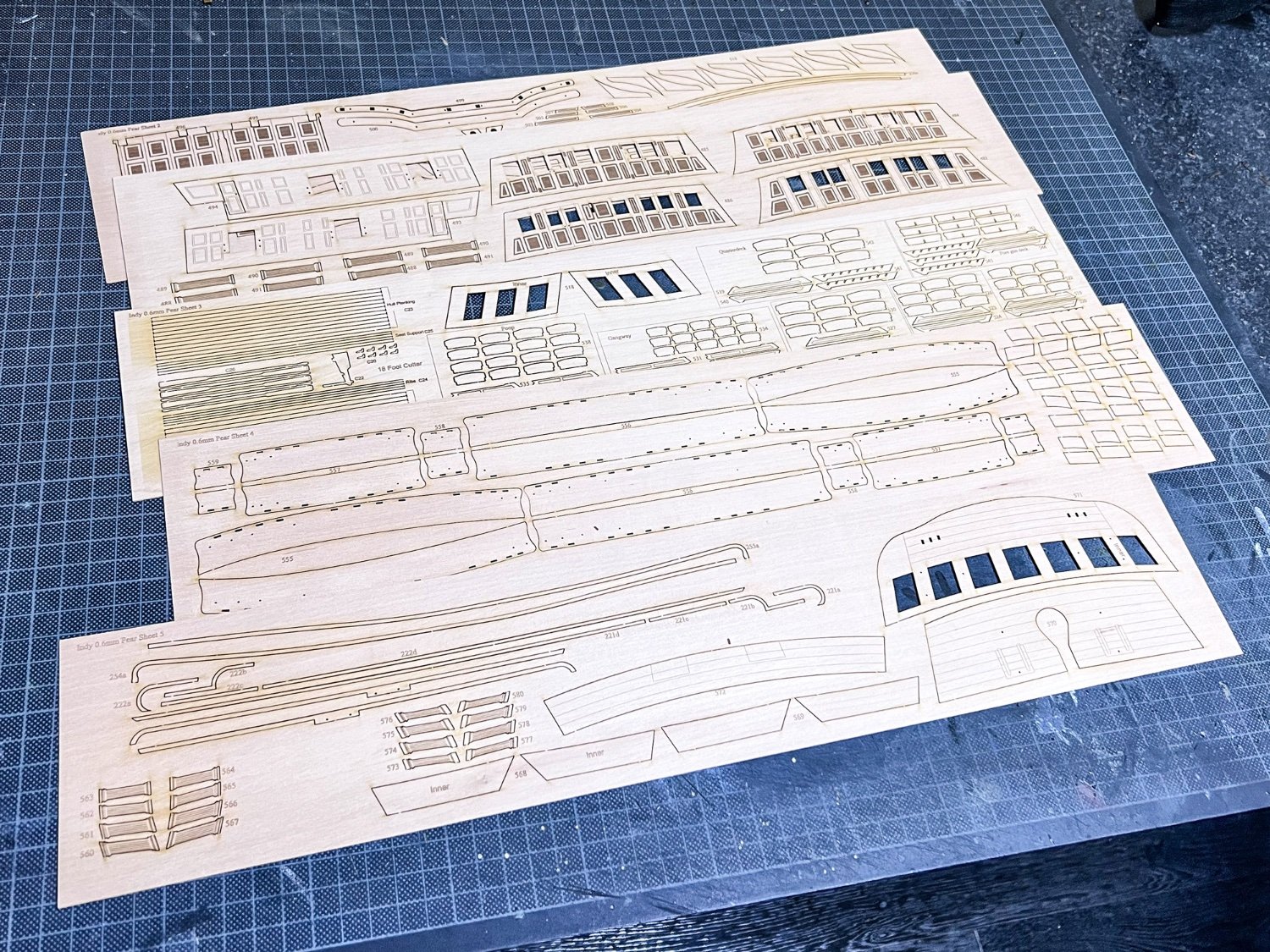
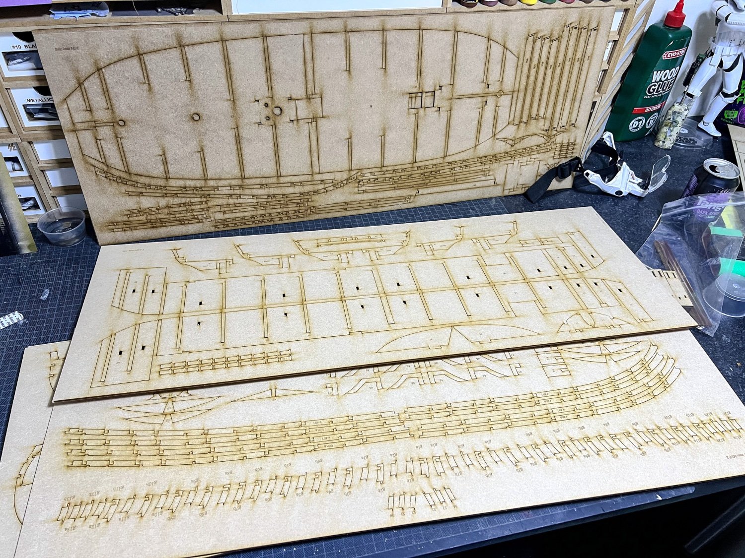
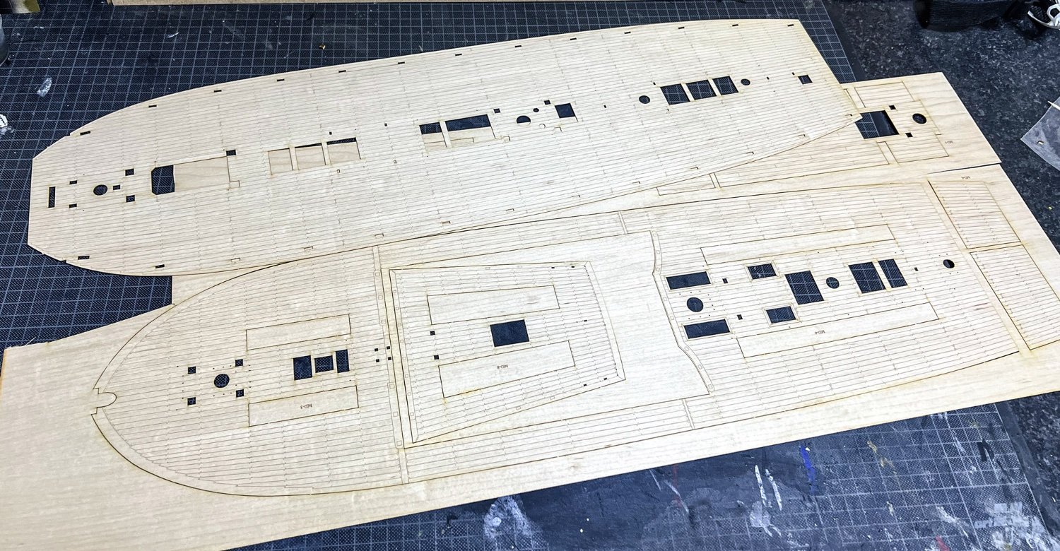
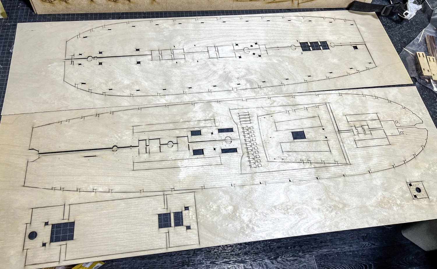
This is the engraved maple deck which won't be included as standard, unlike the other kits. This kit will have traditional planks for the deck, but it is quite likely that this option will be provided on release. If that happens, then the gun carriage location slots aren't likely to be there, and you'll simply open them up if you want use that kit feature. Oh, these parts are BIG!! My cutting mat is in 1cm squares, as a guide.
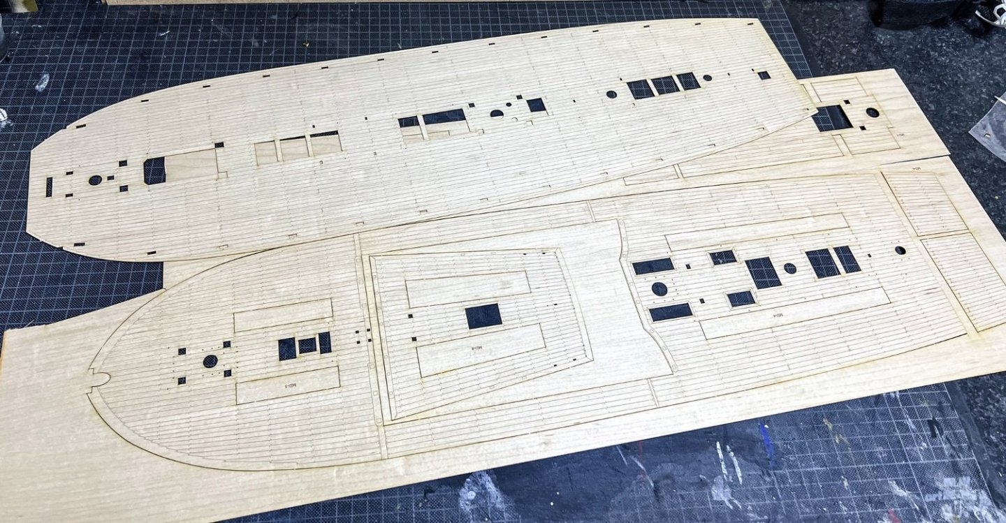
Not fantastically clear here, but the ply sub decks are engraved with planks. This isn't the finish. It's designed to give you a template onto which to lay the kit planks. That will save the modeller having to mark up stuff themselves.
-
5
-
-
A little history (edited from wiki!)
HMS Indefatigable was one of the Ardent-class 64-gun third-rate ships-of-the-line designed by Sir Thomas Slade in 1761 for the Royal Navy. She was built as a ship-of-the-line, but most of her active service took place after her conversion to a 44-gun razee frigate. She had a long career under several distinguished commanders, serving throughout the French Revolutionary Wars and the Napoleonic Wars. She took some 27 prizes, alone or in company, and the Admiralty authorised the issue of four clasps to the Naval General Service Medal in 1847 to any surviving members of her crews from the respective actions.
Indefatigable was ordered on 3 August 1780 (long after Slade's death), and her keel was laid down in May 1781 at the Bucklers Hard shipyard in Hampshire owned by Henry Adams. She was launched in early July 178, and completed from 11 July to 13 September of that year at Portsmouth Dockyard as a 64-gun two-decked third rate for the Royal Navy. She had cost £25,210 4s 5d to build; her total initial cost including fitting out and coppering was £36,154 18s 7d (around £6.6m in today's money). By that time, she was already outmoded for the role of a ship of the line as the French only built the more powerful 74-gun ships, and she was never commissioned in that role.
She was broken up in 1816.
The kit
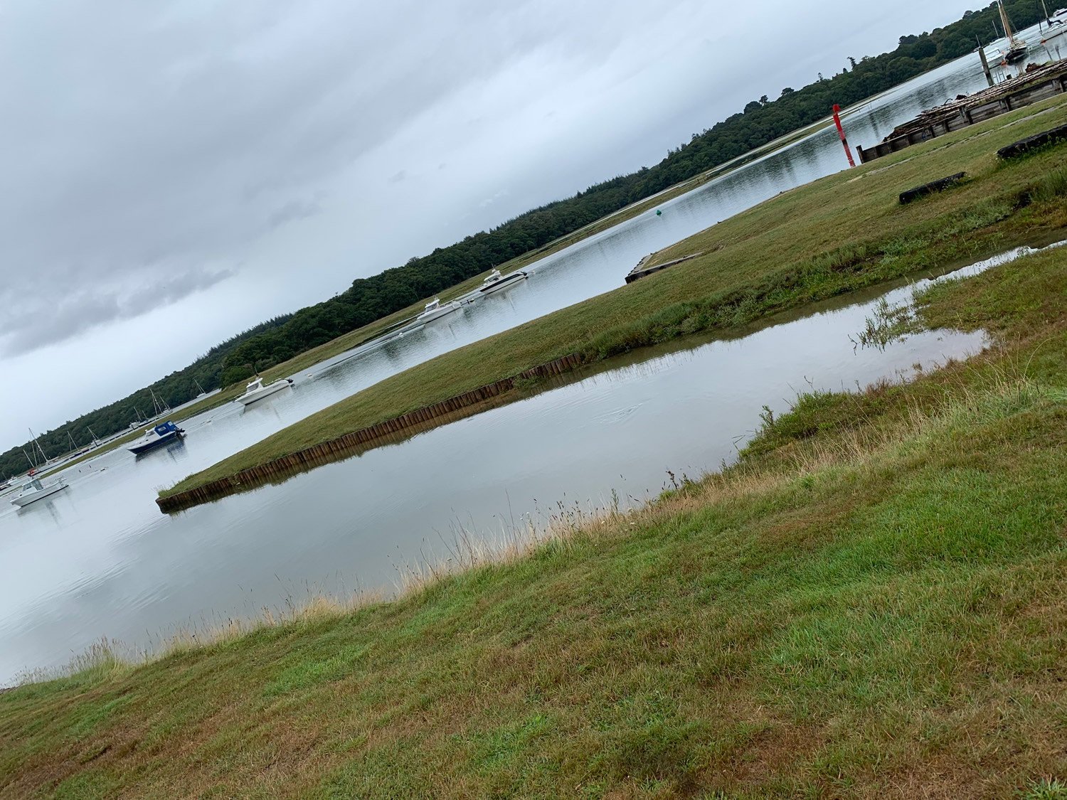
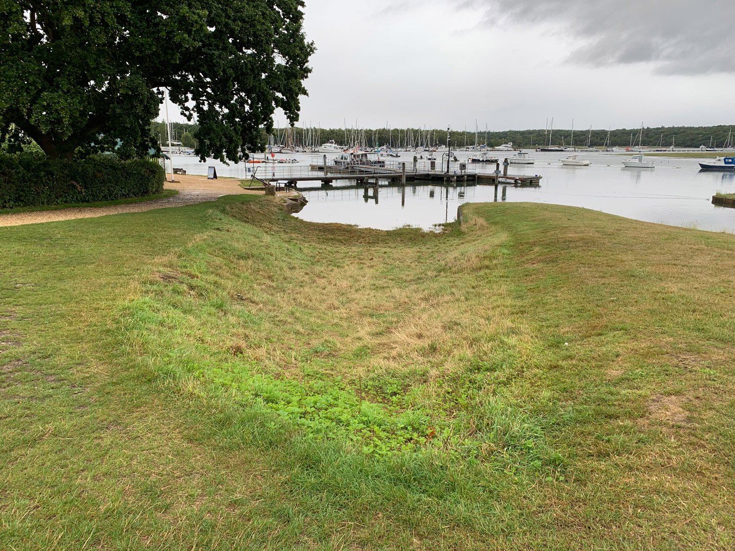
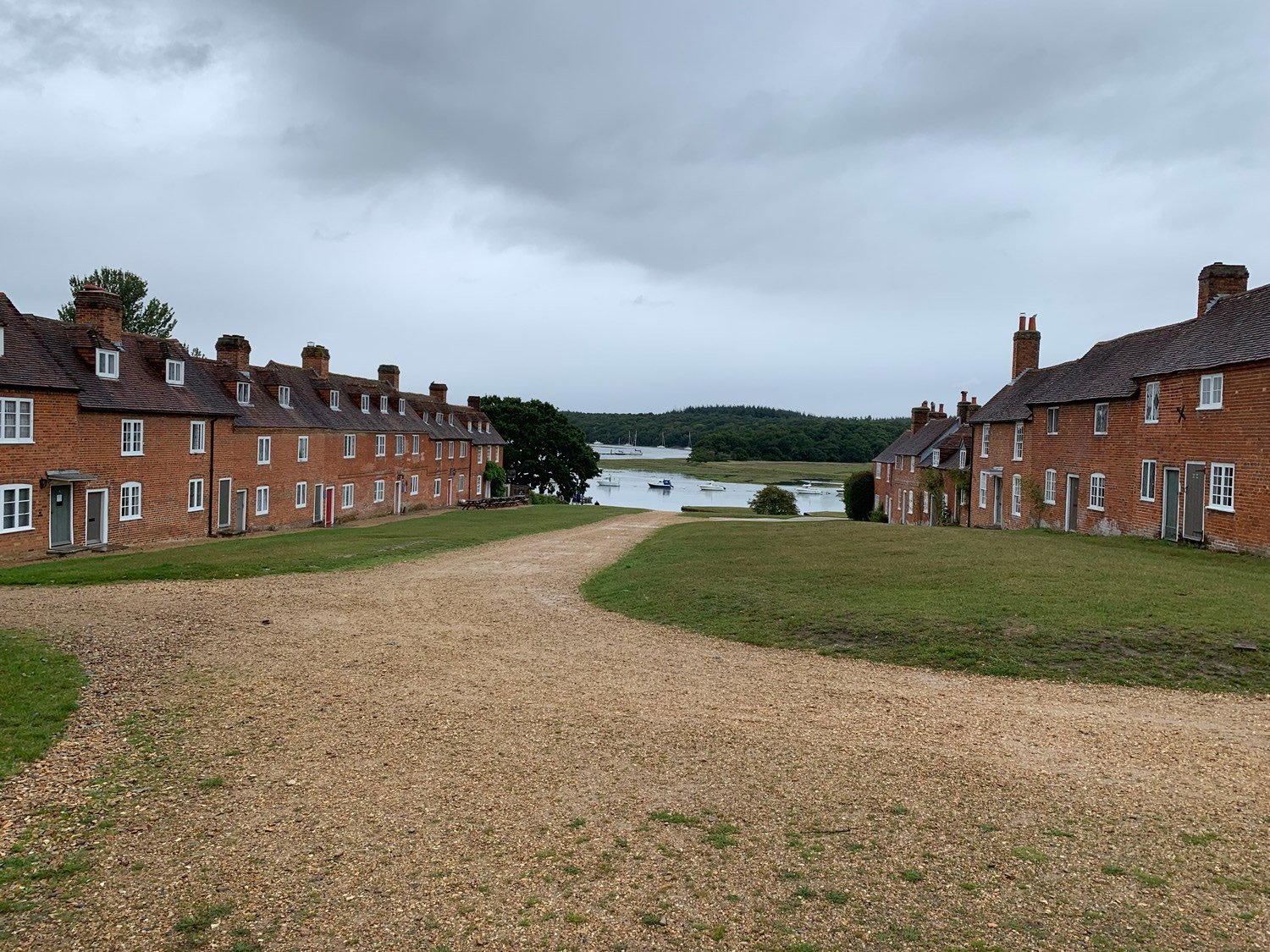
This is quite literally hot off the press with regards to what you see here. Indefatigable is being represented in this new kit as the razée, and quite rightly so. I do have a lot of affection for the stuff built at Bucklers Hard, having visited there a couple of times myself. It's a beautifully tranquil place in England's New Forest, which really does betray the hive of activity it used to be. It even has the original shipwrights houses and the pub there, as part of the tour. Just to think, Indefatigable was definitely built in one of these two slips, as was Agamemnon etc. I took these photos a couple of years ago.


This is very stuff for Indefatigable, as all I currently have are the cannon, carronades, and also the cutter. It will also become very obvious that when building these models, I never do anything in chronological order as seen in the manual. I work on whatever Chris has completed and sends over to me, with other work infilling between main tasks. I try to waste as little time as possible in order to keep to fairly tight release schedules. For the first time you'll see me work on stuff like this before the big hitters are sent to me. Even then, I will feed back with my findings and things will possibly be changed to reflect my own build.
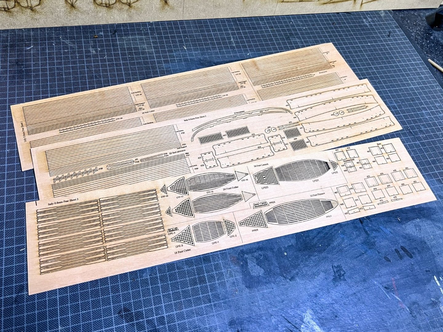
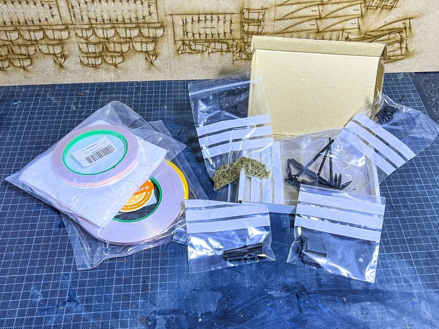
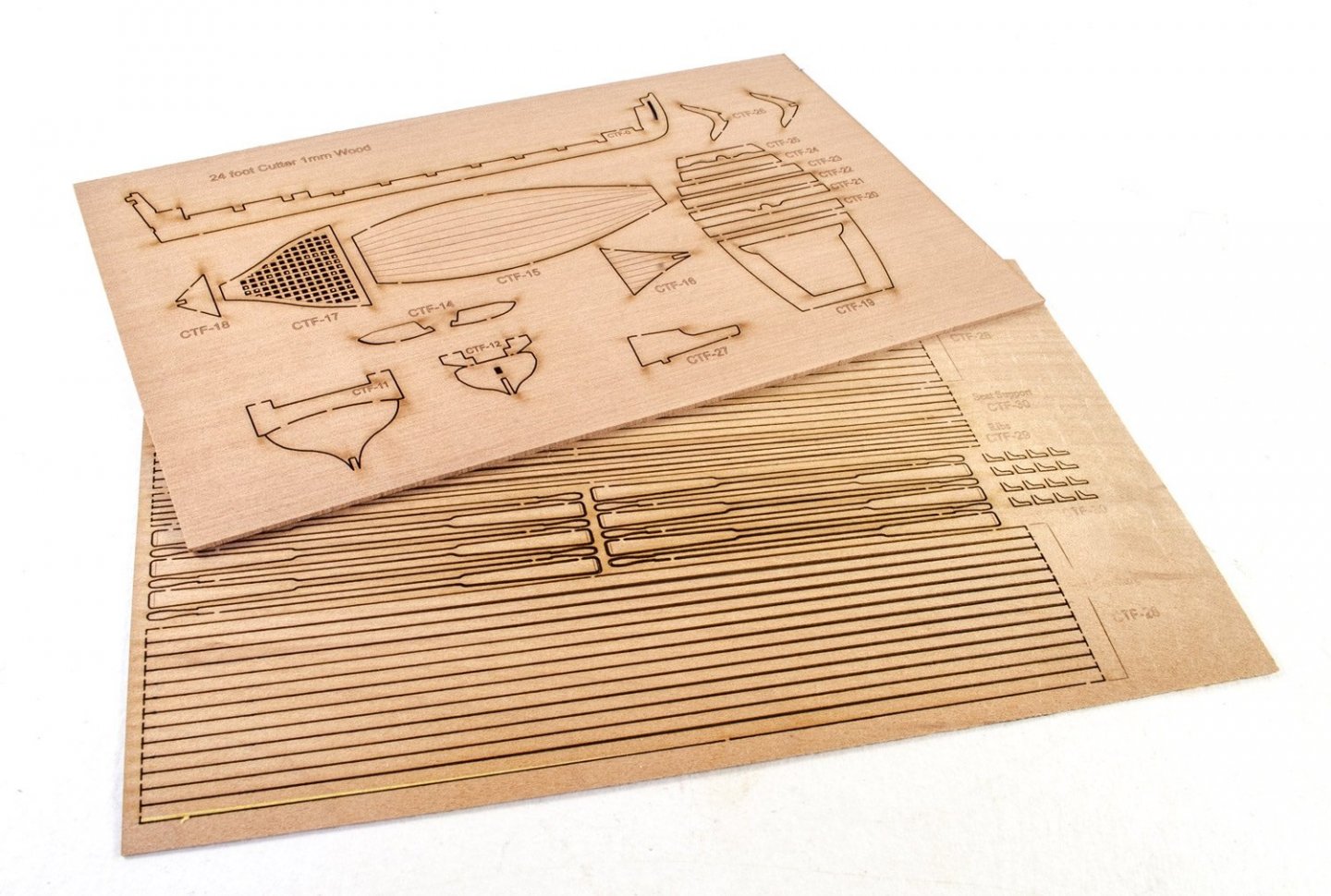
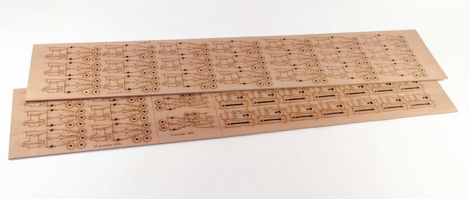
Not too much to see at the moment, and work won't start proper for a week or so, so keep checking in to see if things have progressed. Here's the two sheets of 2mm pear which contain the gun carts...


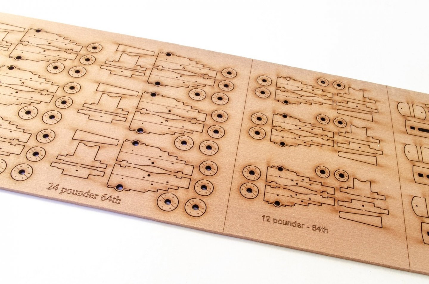
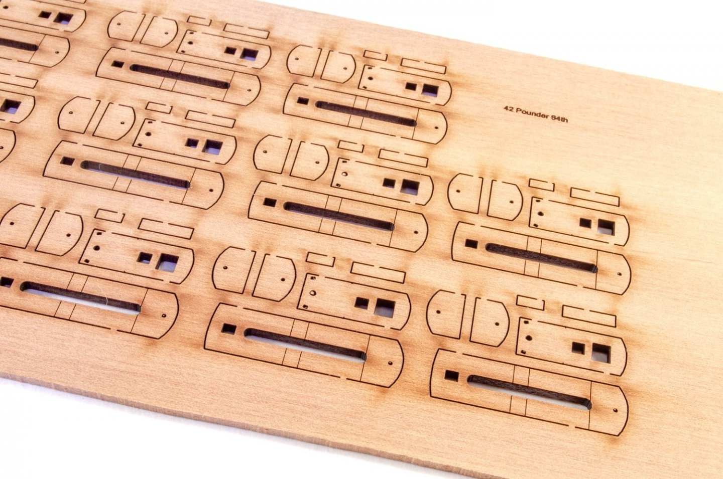
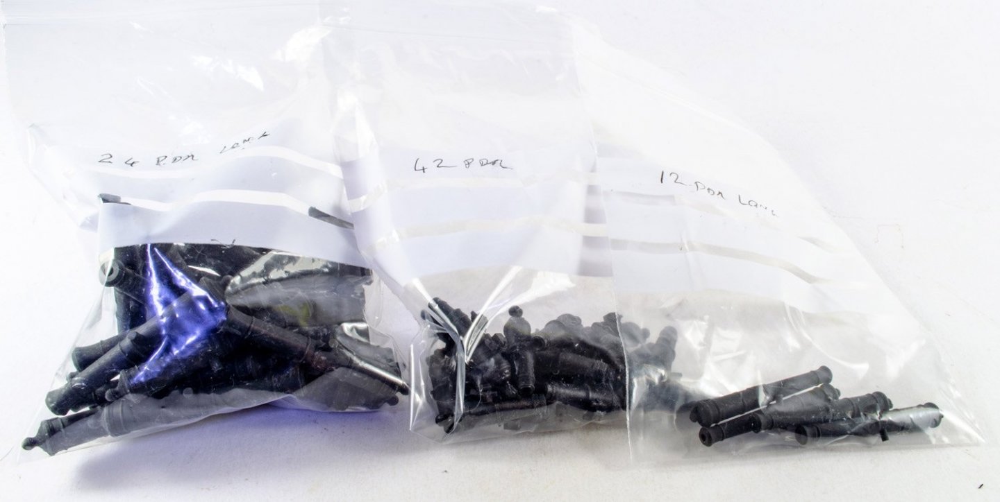
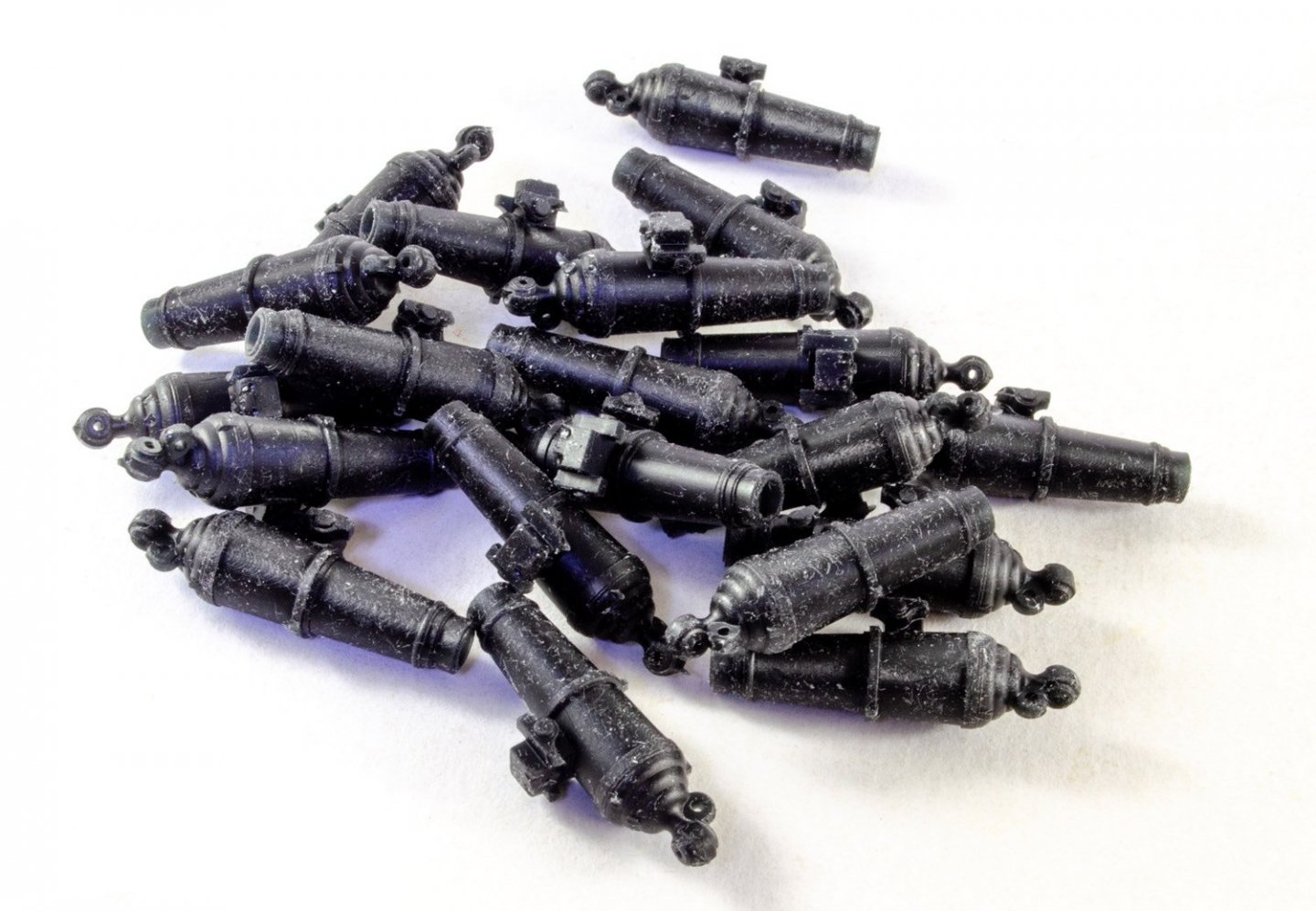
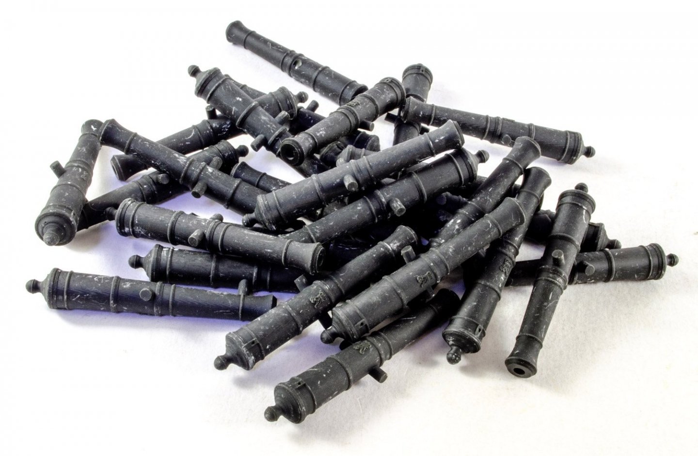
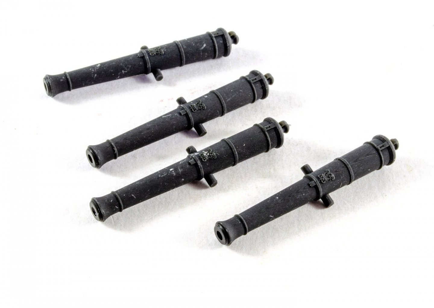
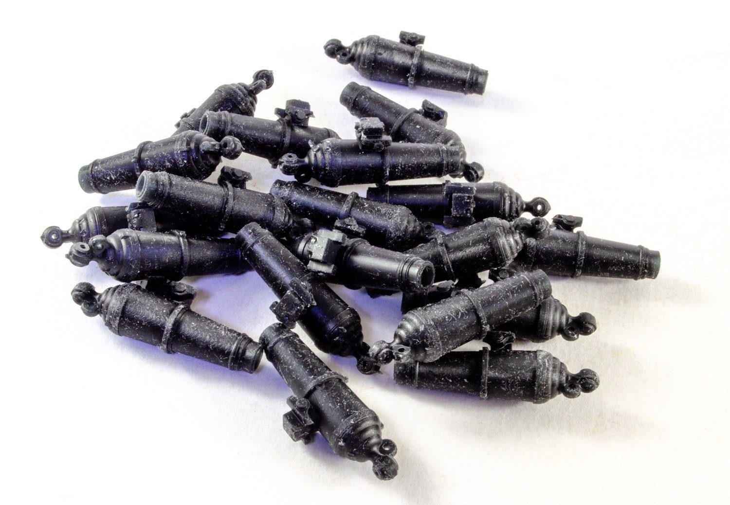
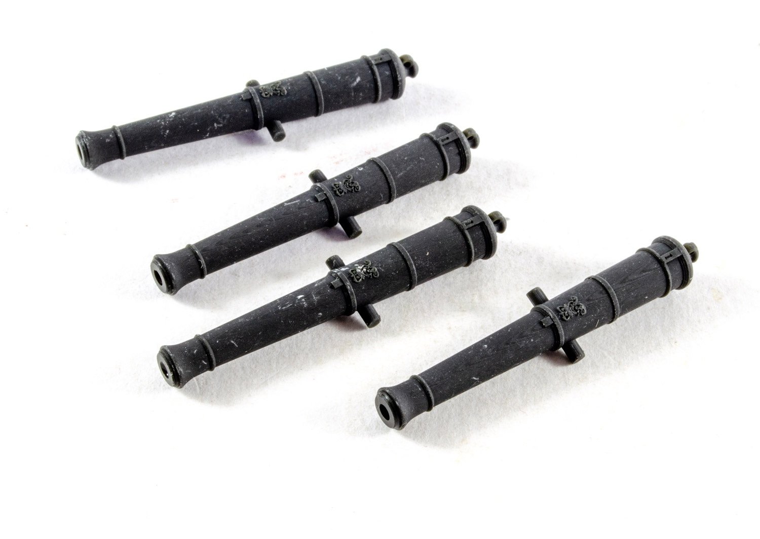
I also have three bags of guns. These are:
- 12-pound long
- 24-pound long
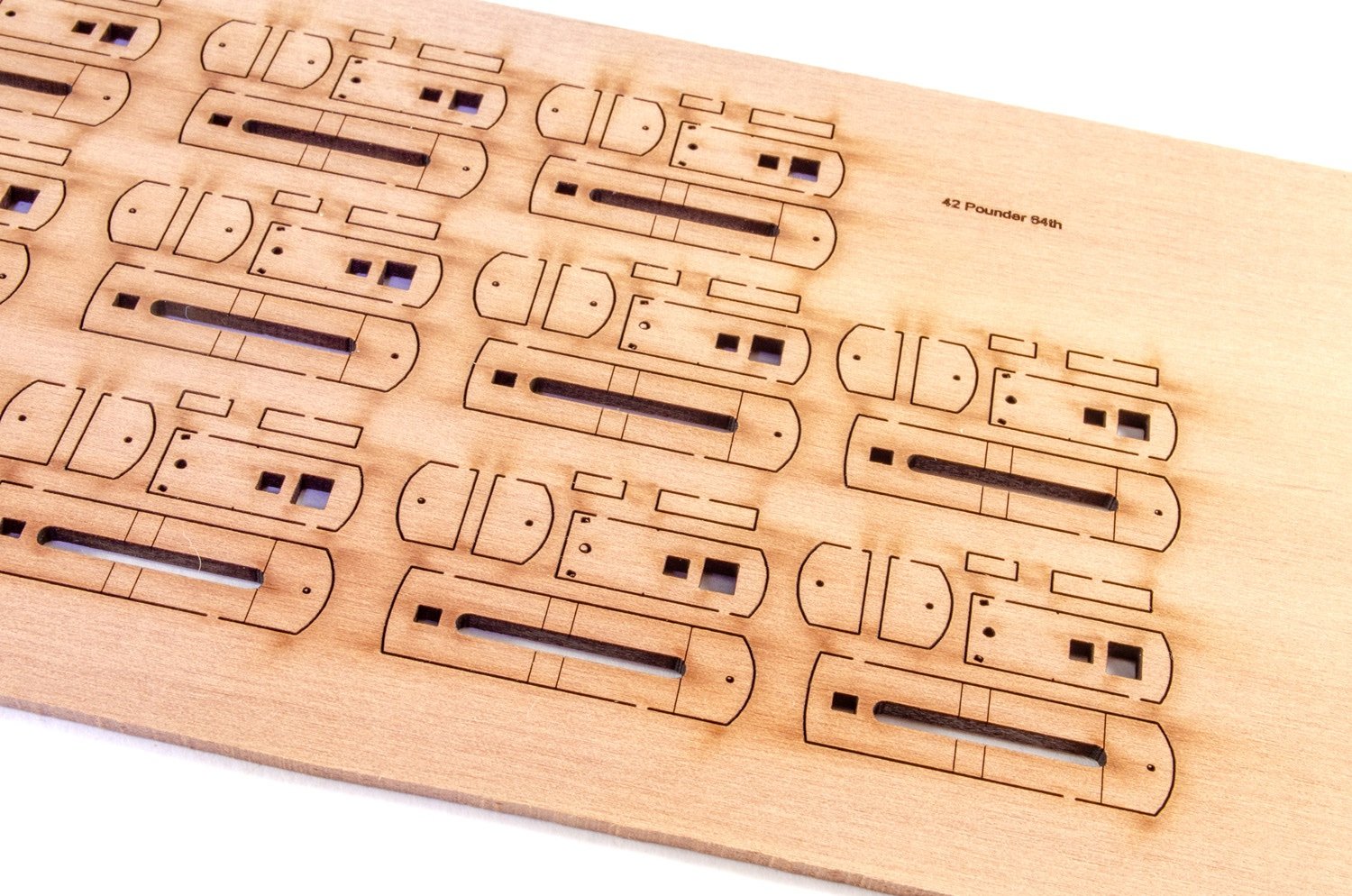
- 42-pound carronades
I do need to wash these guns in some isopropyl, especially the carronades as the initial washing left then with tissue debris on them. Also, the carronade carriages will also have 3d-printed wheels!
Indefatigable will have many of the design traits of Sphinx, but this time incorporate more traditional planking around the upper bulwarks and gun ports etc. Indy will also feature a traditionally planked deck too.
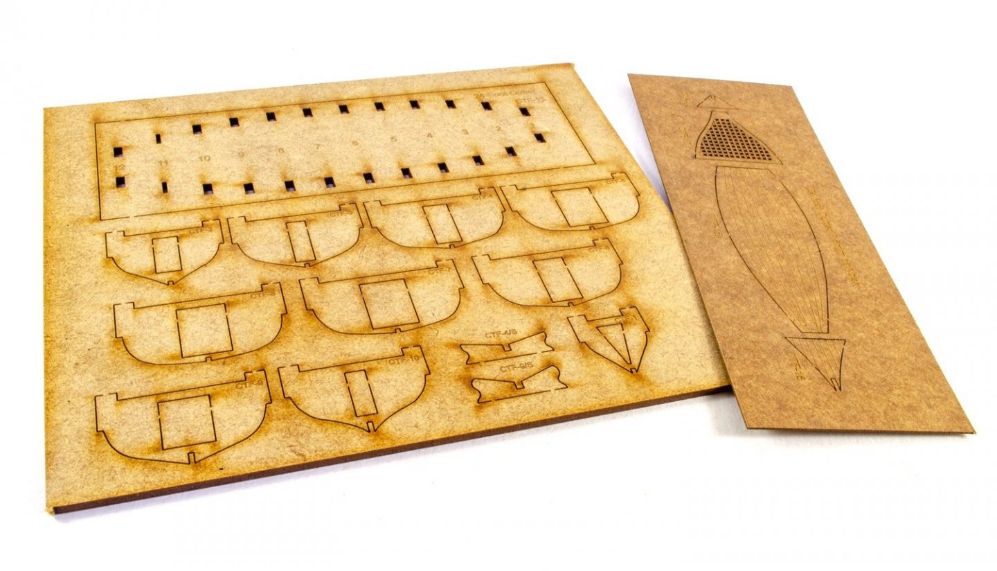
Here are the parts for the cutter:
-
4
-
I really don't know what to say about the engineering choices on this kit, except that you'd think ZM would learn a little from previous kits which were over-fussy to assemble, going right back to the dog turd that's the P-51D.
I really, really was thinking about the forthcoming Henschel Hs 129B-3, but don't know if I should be spending hard-earned cash at a time like this.
Kudos in cracking on with this build.
-
4
-
 2
2
-
-
This is something I just can't replicate.
Have you tried a different browser?
-
I just can't seem to replicate this. Try to send me the same image in a PM.
-
1
-


1:64 HMS Indefatigable (1794) - prototype for Vanguard Models
in Non LSM 'WIP
Posted
And more...
Knees(?) now added, as well as a painted brick floor for the stove.
And the gun carts now have some colour applied to them, as well as ironwork and wheels. Remember, these won't be fitted with barrels until the model is more or less complete.
Capstan finally done.
As are the hand pumps.
No one wants to walk down stairs without a safety rope around them!
And the stove makes an appearance.
And this is Indy up to date. Back in the shipyard tomorrow")