GunnarO
-
Posts
42 -
Joined
-
Last visited
Content Type
Profiles
Forums
Events
Gallery
Everything posted by GunnarO
-

1/32 Westland Whirlwind
GunnarO replied to JeroenPeters's topic in LSM 1/35 and Larger Work In Progress
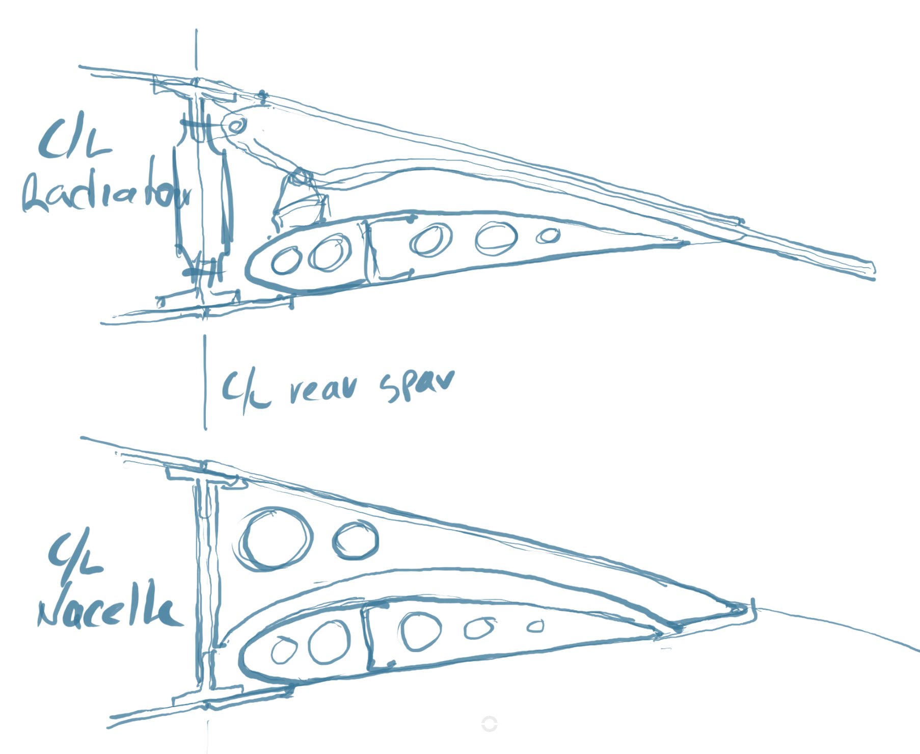
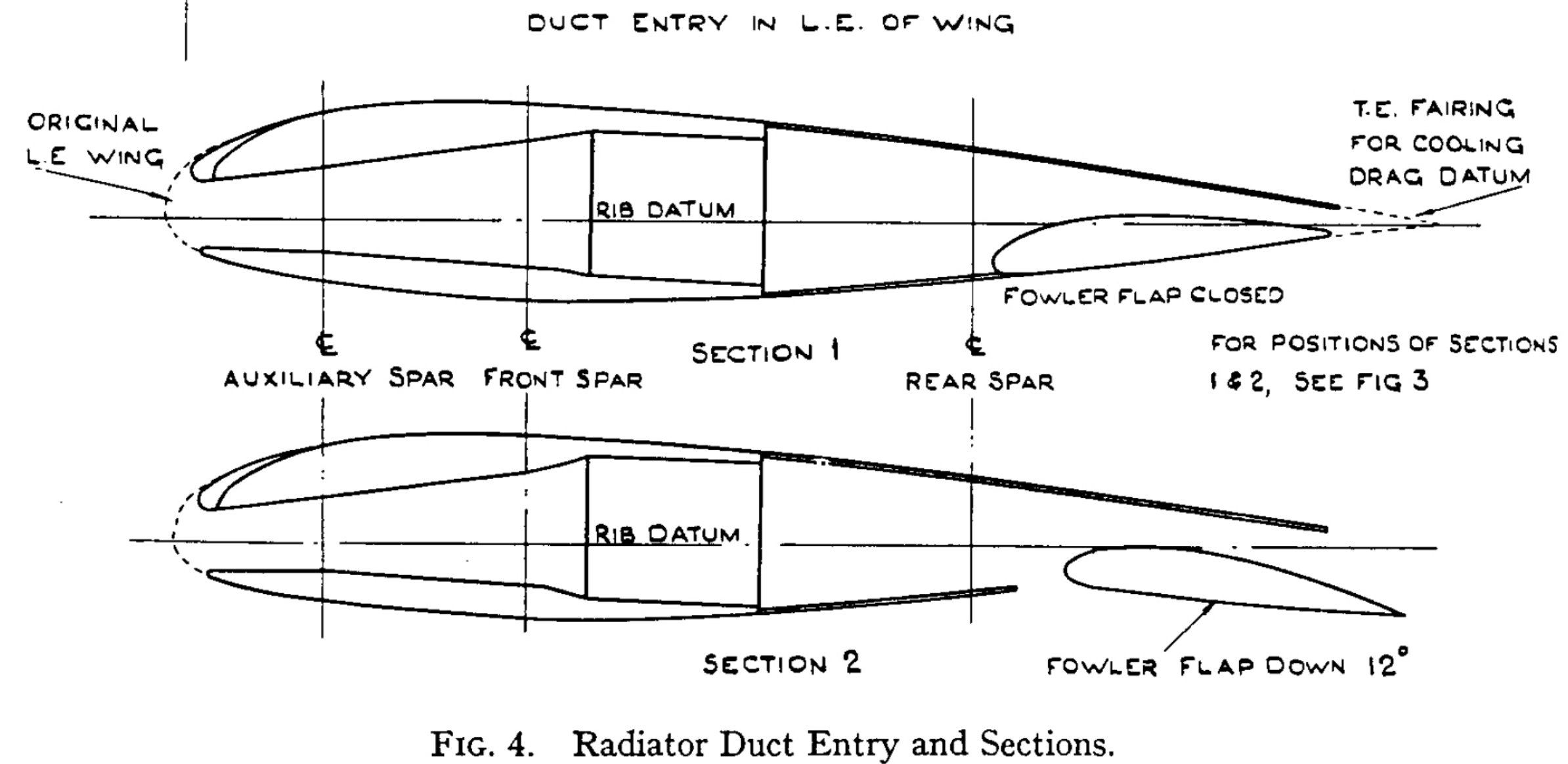
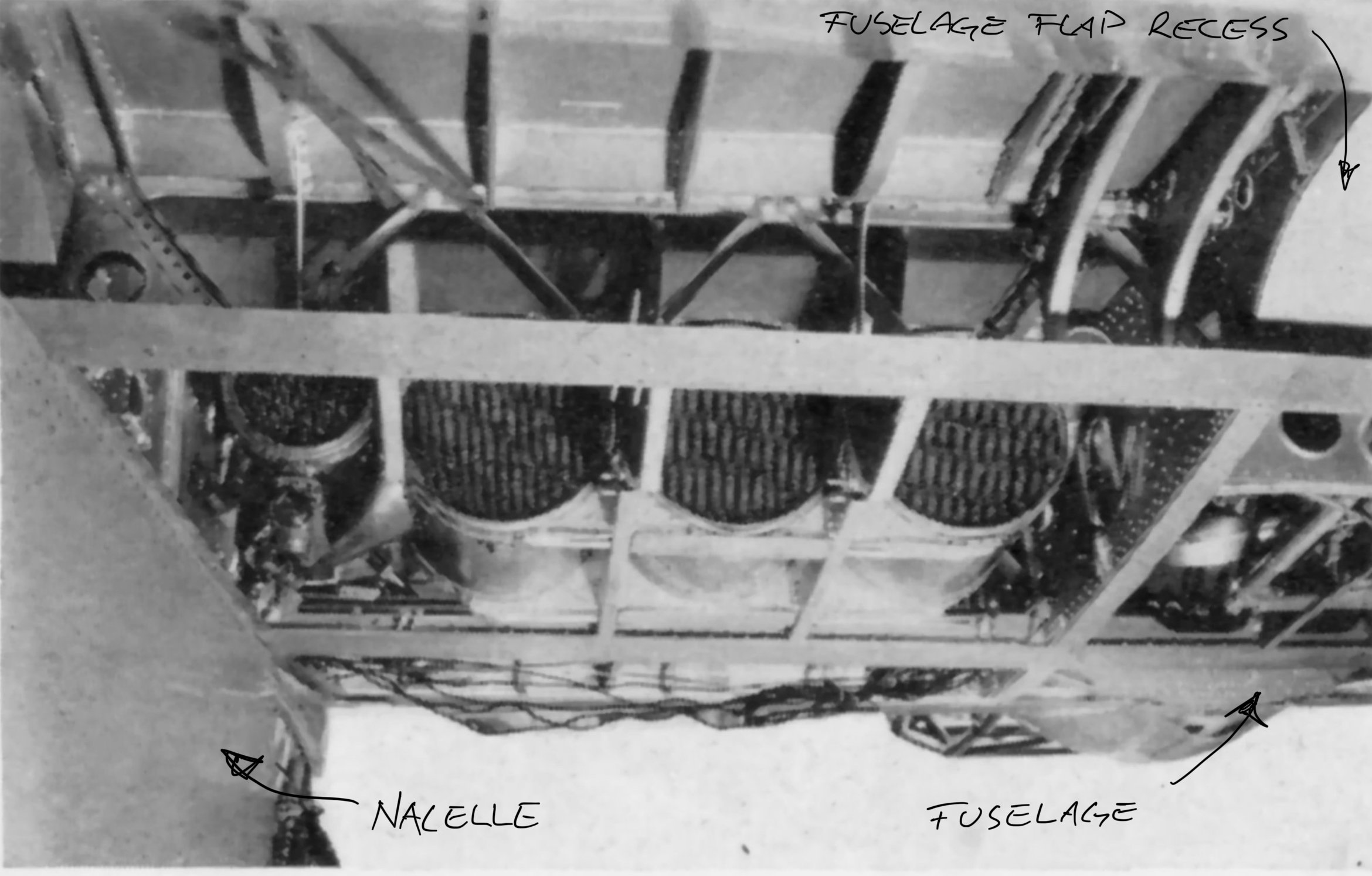
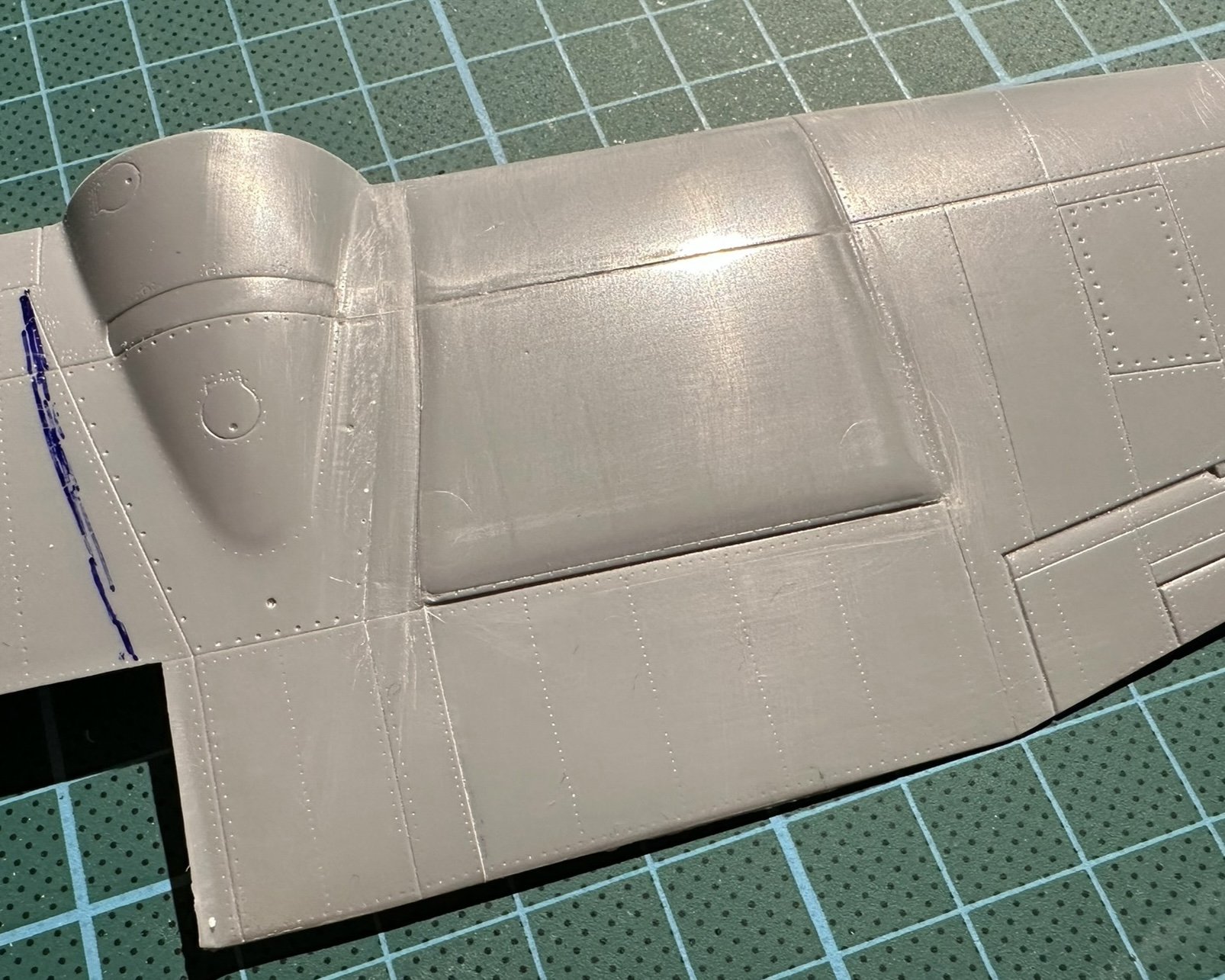
The rear “panel line” on the flap is actually dividing the flap and the rear edge of the wing. That part of the wing is removed on the inside of the nacelle where the radiator flaps are located. if this makes any sense…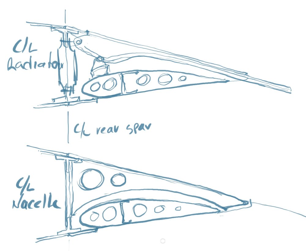
-
1/32 Westland Whirlwind
GunnarO replied to JeroenPeters's topic in LSM 1/35 and Larger Work In Progress
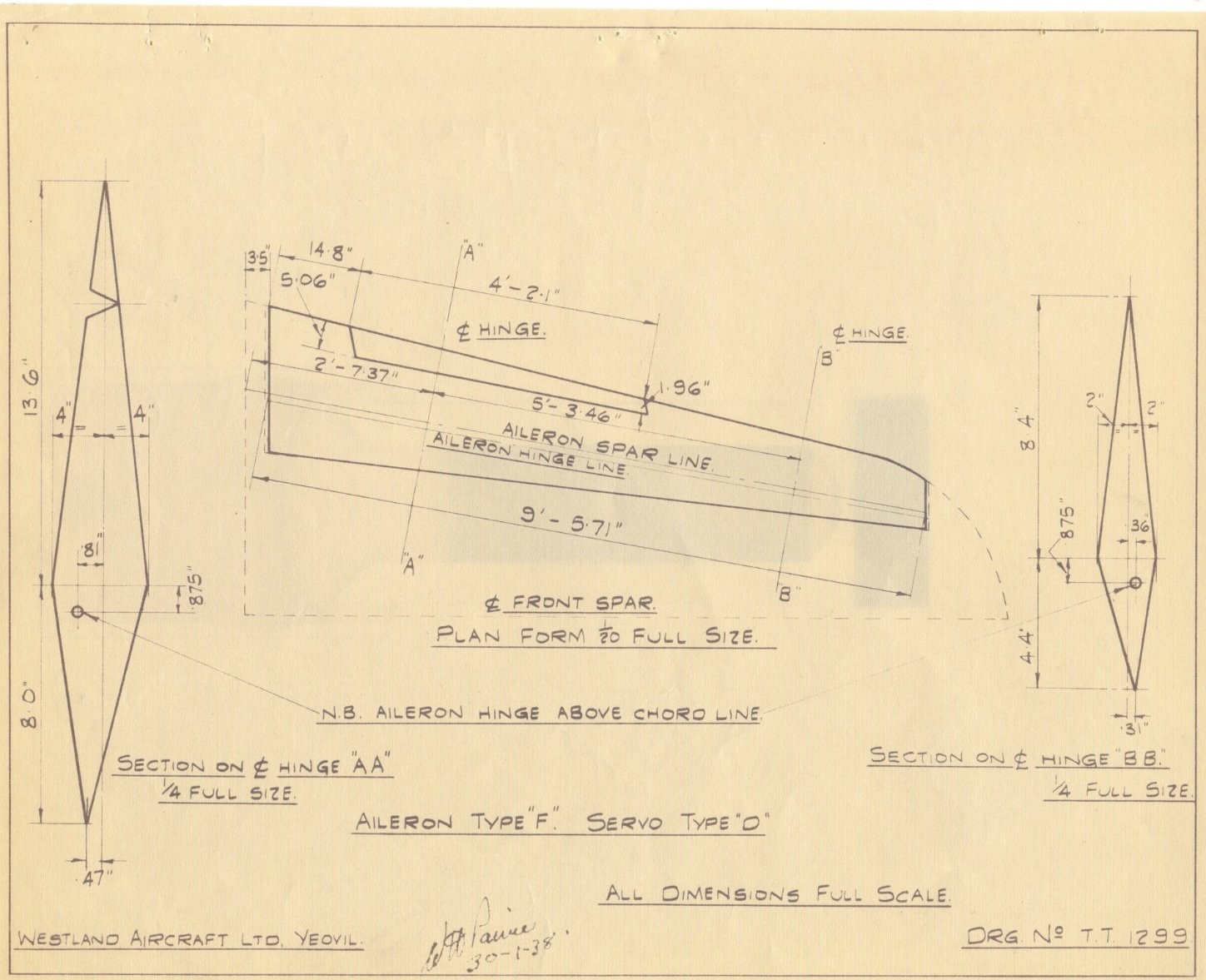
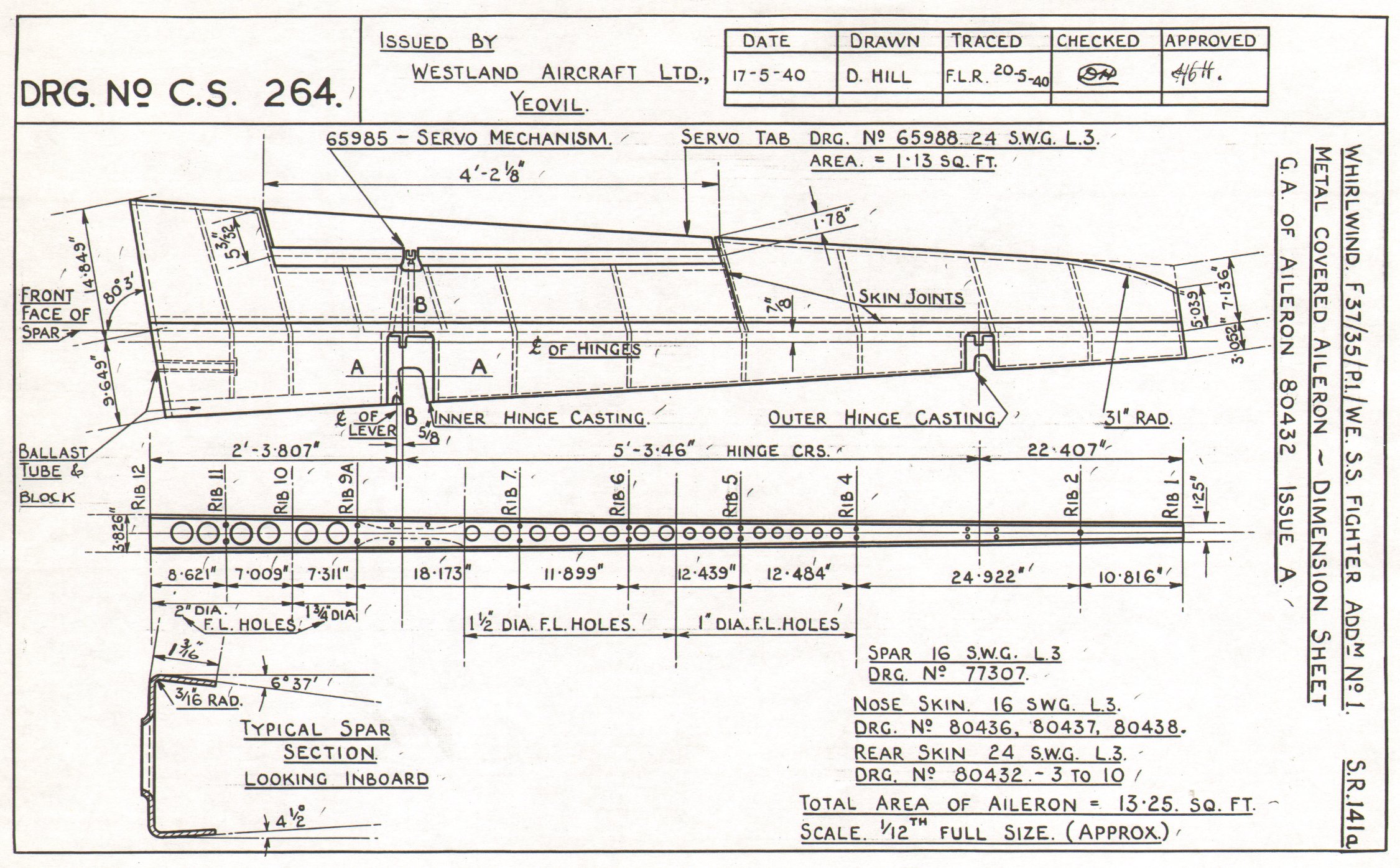
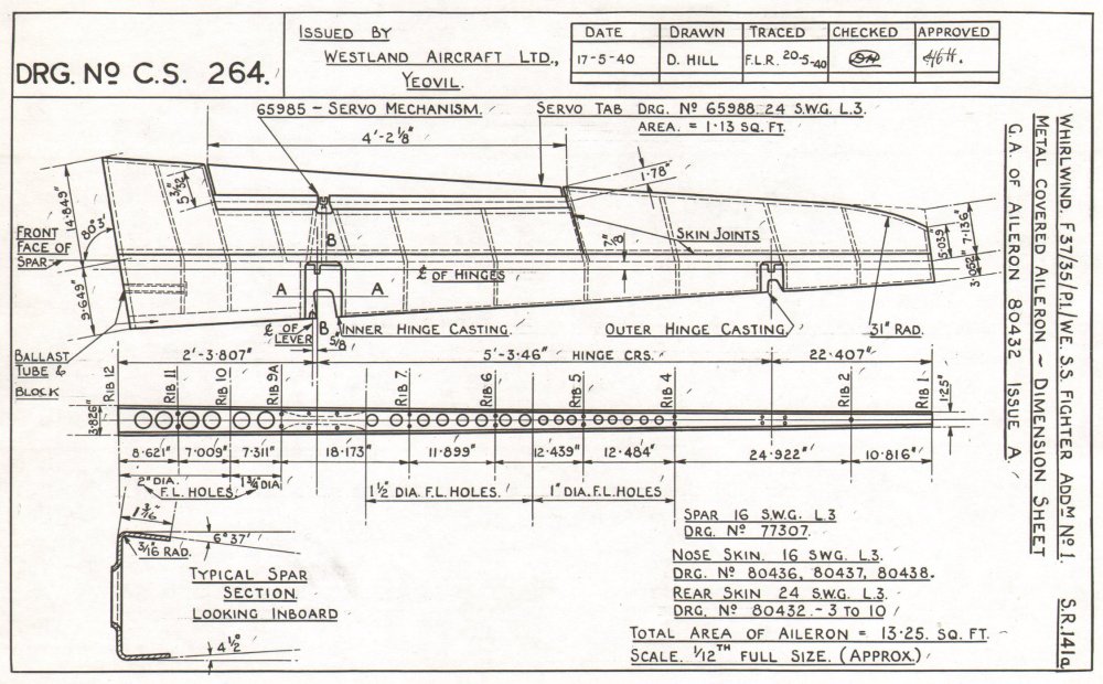
The drawings are showing early designs, some of them are pre production. During prototype testing many changes were made and we don’t have the latest versions of the drawings. Use photos and measure the length of the trim tab compared to the length of the aileron. The length of the aileron is known. -
1/32 Westland Whirlwind
GunnarO replied to JeroenPeters's topic in LSM 1/35 and Larger Work In Progress
Note that this instrument layout was only used by the first 18 Whirlwinds with serial numbers up to and including P6983. Later aircraft had the Blind Flying Panel Mk.1A with radius on top. -
1/32 Westland Whirlwind
GunnarO replied to JeroenPeters's topic in LSM 1/35 and Larger Work In Progress
Great job Jeroen. This might come in handy.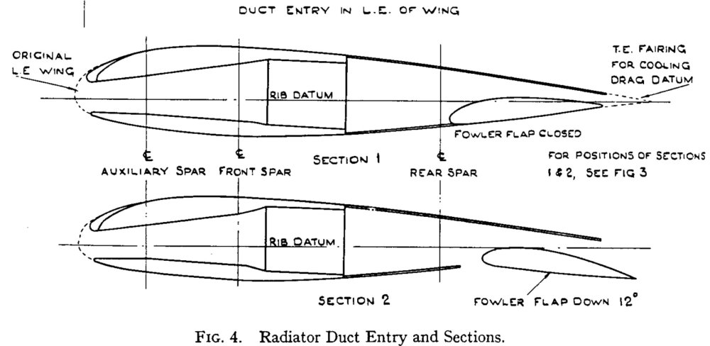

-
1/32 Westland Whirlwind
GunnarO replied to JeroenPeters's topic in LSM 1/35 and Larger Work In Progress
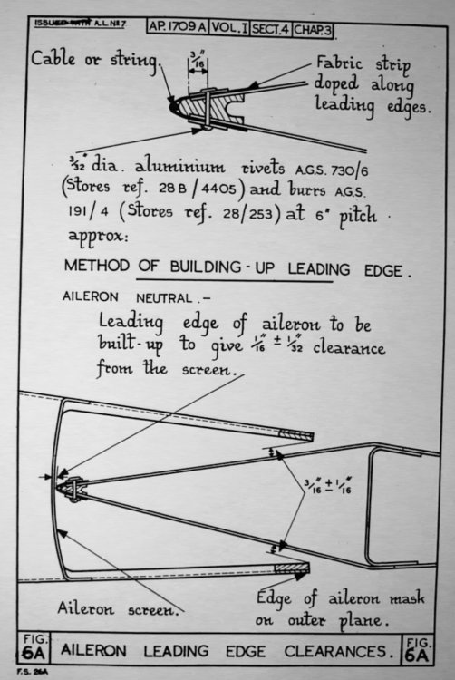
You are correct that it’s wrong… the ailerons are diamond shaped. The spar you have placed in front on the ailerons are actually in the middle. Most of it is hidden inside the wing though. -
1/32 Westland Whirlwind
GunnarO replied to JeroenPeters's topic in LSM 1/35 and Larger Work In Progress
Note the sharp edges on the ailerons.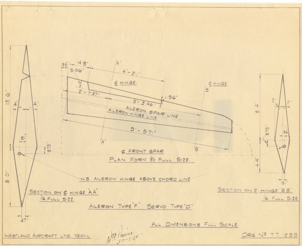
-
1/32 Westland Whirlwind
GunnarO replied to JeroenPeters's topic in LSM 1/35 and Larger Work In Progress
File and sandpaper will work out just fine 😊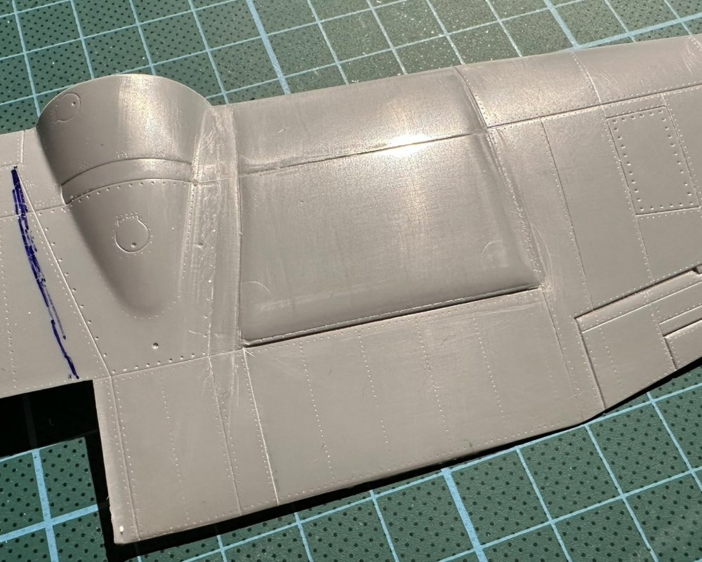
-
1/32 Westland Whirlwind
GunnarO replied to JeroenPeters's topic in LSM 1/35 and Larger Work In Progress
Will you correct the upper wing fuel tank as well? A shame they didn’t compare the upper and lower wing fuel tank as they should be similar in width. Some details for the aileron added 😊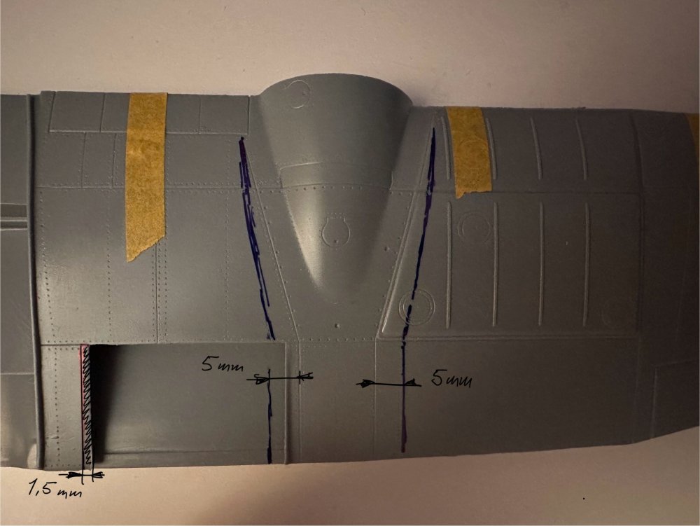
-
1/32 Westland Whirlwind
GunnarO replied to JeroenPeters's topic in LSM 1/35 and Larger Work In Progress
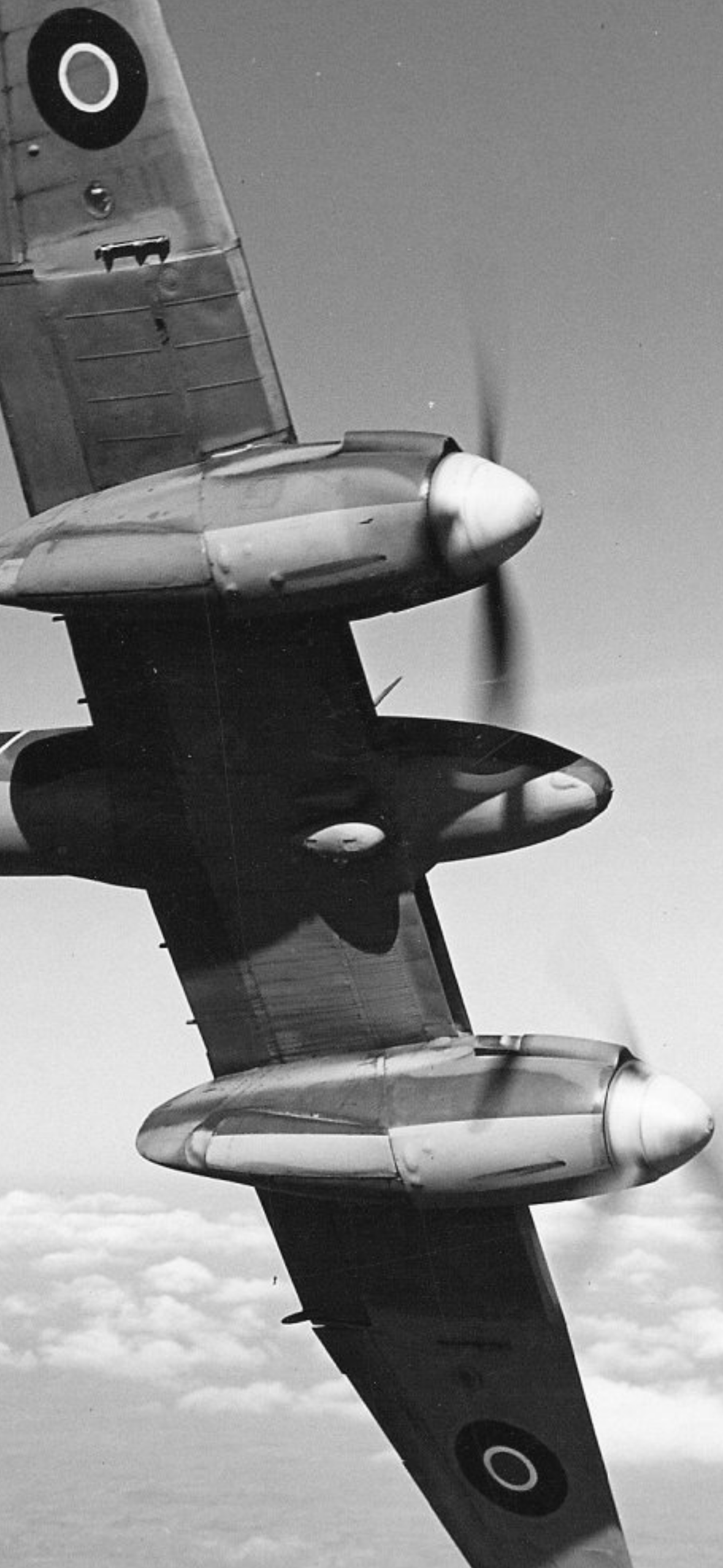
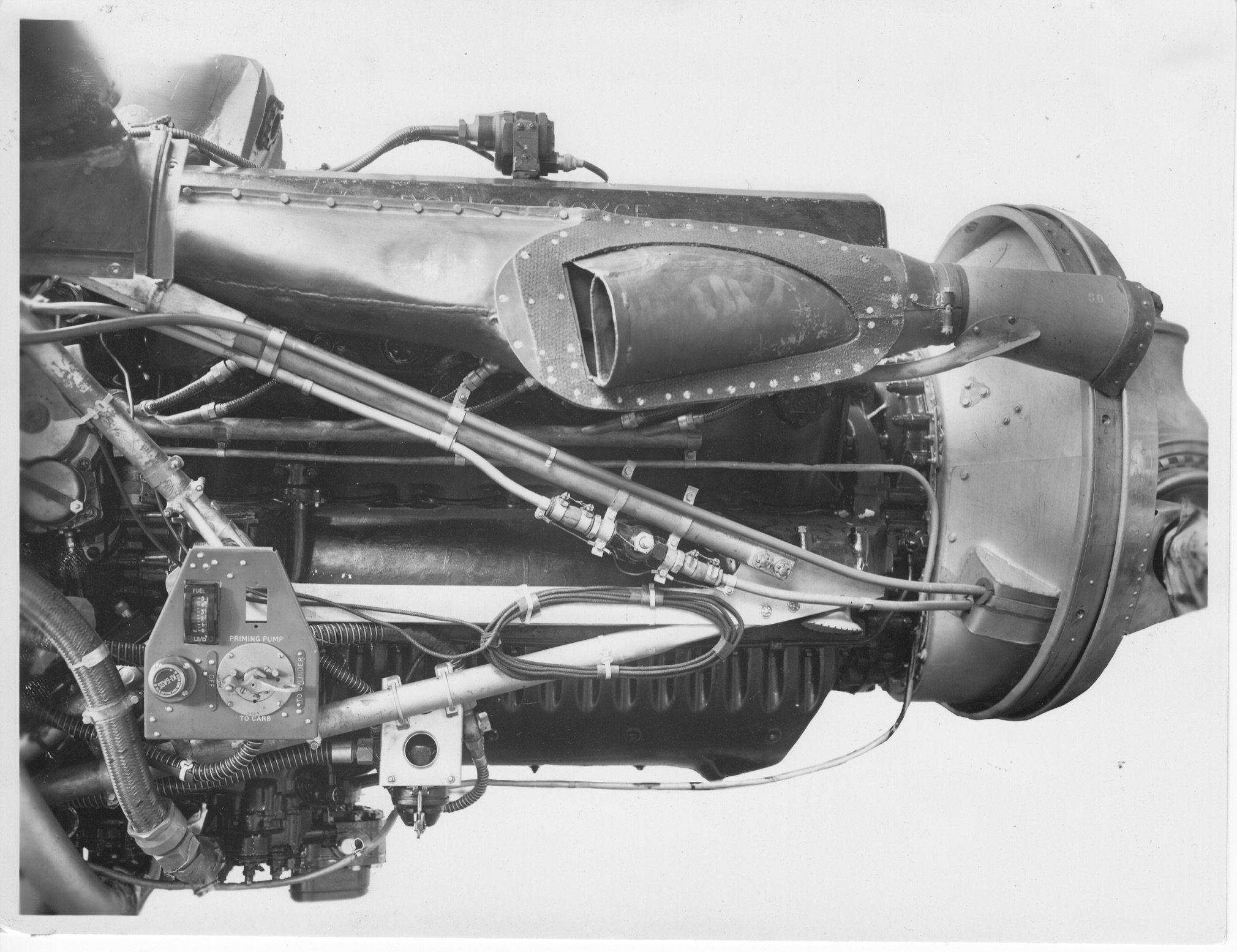
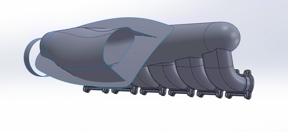
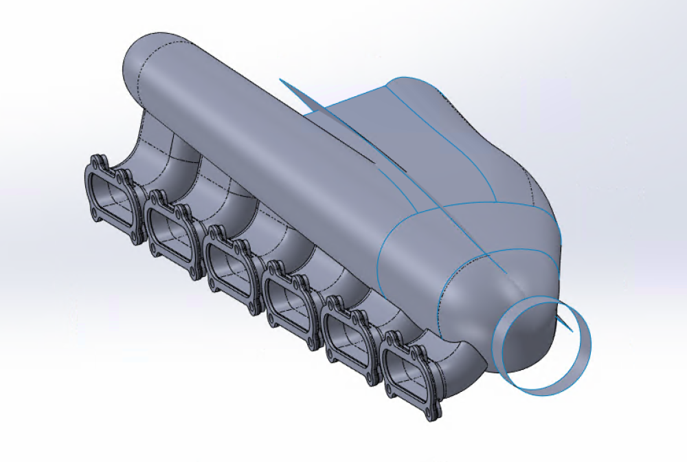
That is correct, the outboard exhaust is shortened. Part of the plates between the exhaust outlet and the manifold are also removed on both the short and the long exhaust compared to the drawing. The cowling is not connected to the exhaust but it covers the transition between the air intake in front and the exhaust outlet (on the short one) -
1/32 Westland Whirlwind
GunnarO replied to JeroenPeters's topic in LSM 1/35 and Larger Work In Progress
Starting to look good. Note that the exhaust stubs have different lengths on the inside and outside of the engine. In our CAD world we can of course mirror one side to the other but in the days they made 4 different exhaust systems on the plane 🤪
-
1/32 Westland Whirlwind
GunnarO replied to JeroenPeters's topic in LSM 1/35 and Larger Work In Progress
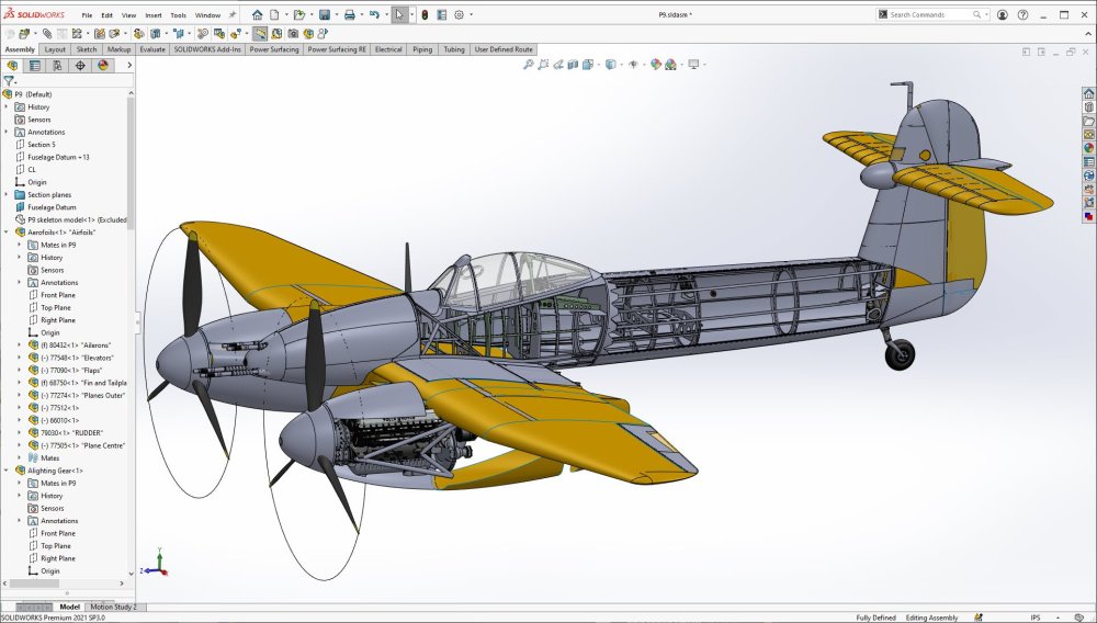
This is my work. Been working on it for some time but it’s hard to find anything that explains the shape correctly. Very few pictures that shows the exhaust from different angles exist. -
1/32 Westland Whirlwind
GunnarO replied to JeroenPeters's topic in LSM 1/35 and Larger Work In Progress
This might help a bit, but it's still complicated.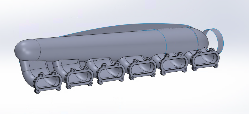
-
1/32 Westland Whirlwind
GunnarO replied to JeroenPeters's topic in LSM 1/35 and Larger Work In Progress
Not the ordinary exhaust system in the late 30's, although probably a lot better than the prototype with exhaust going through the wing.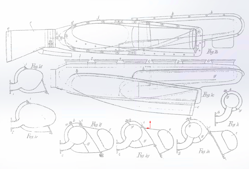

-
1/32 Westland Whirlwind
GunnarO replied to JeroenPeters's topic in LSM 1/35 and Larger Work In Progress
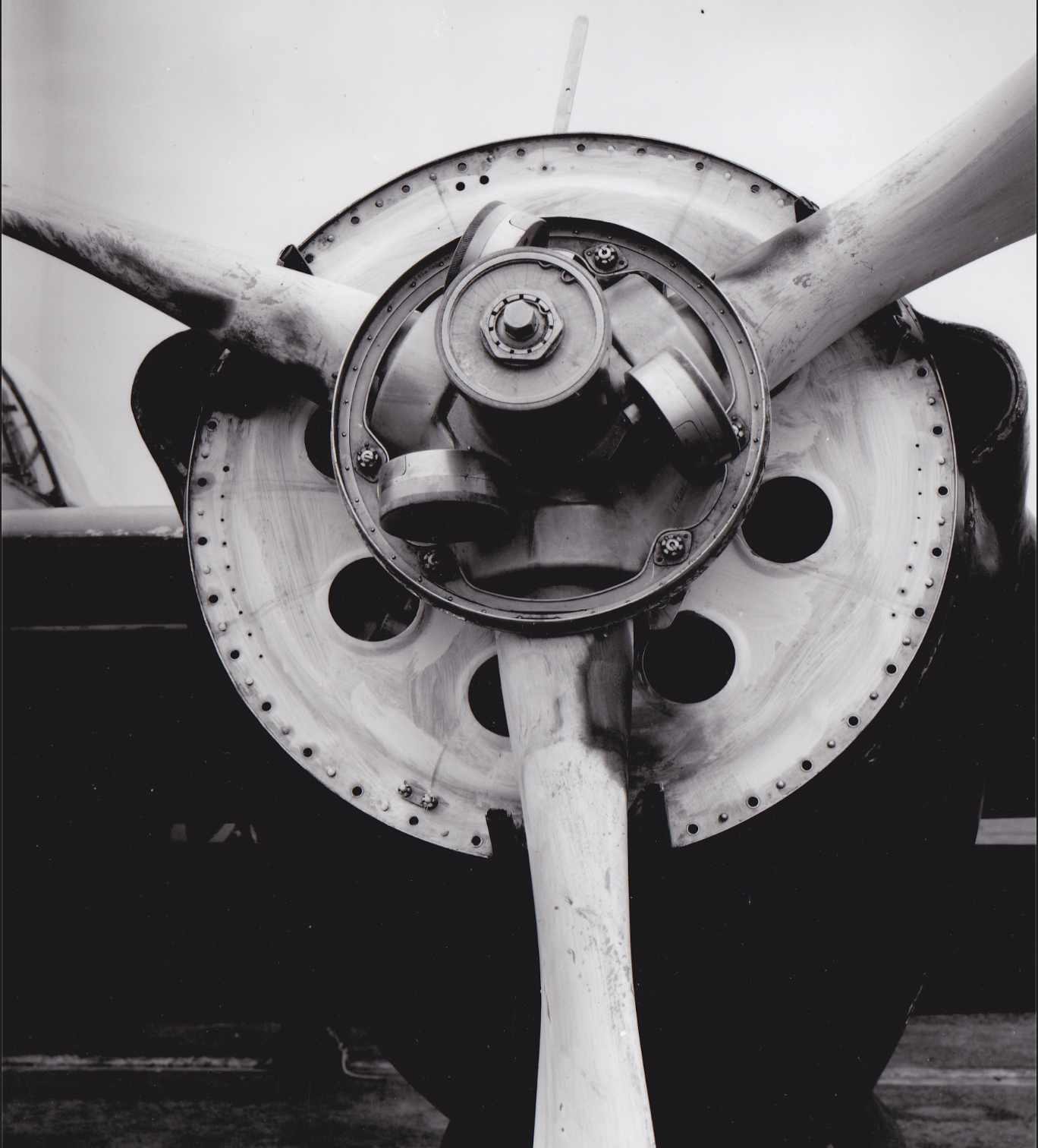
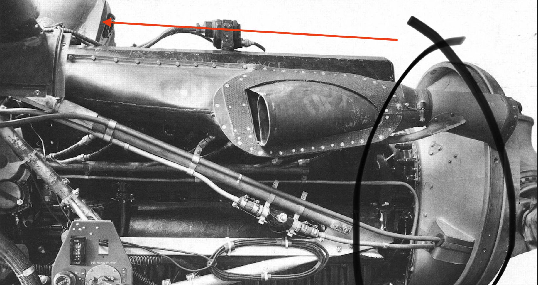
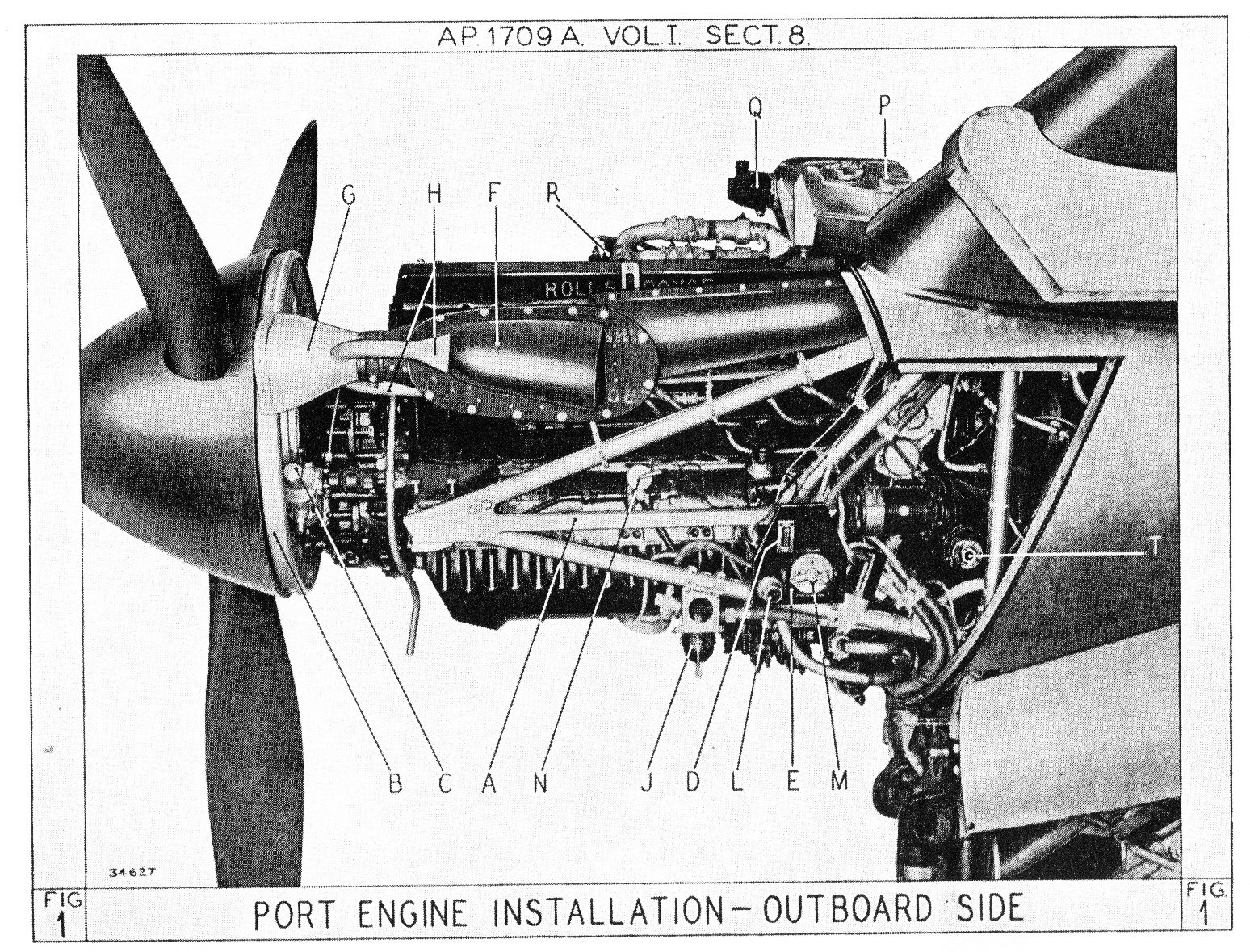
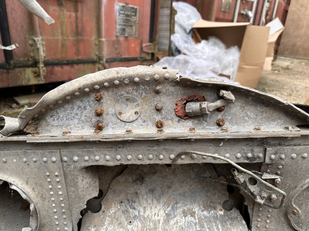
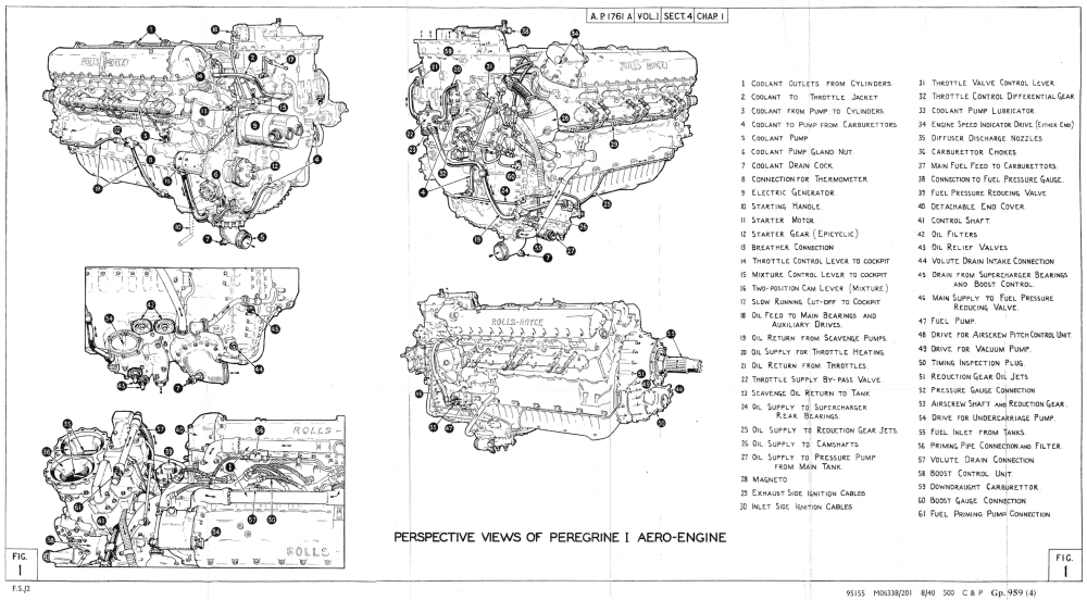
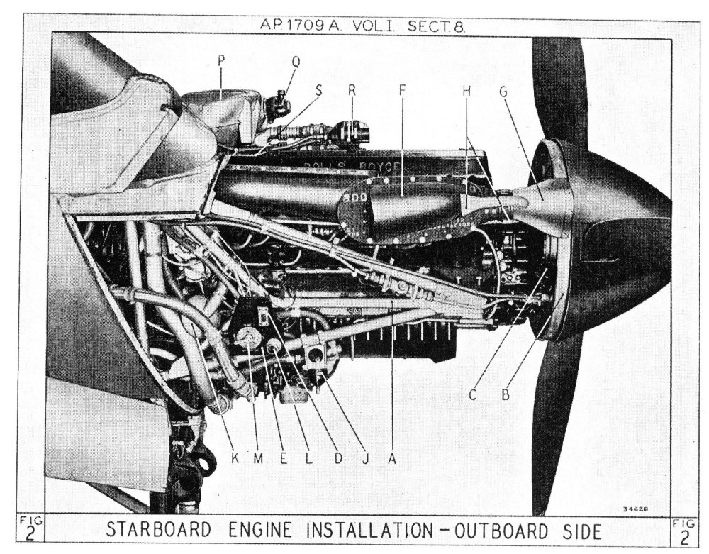
The glycol tank was never behind the spinner. It was on top of the engine from the prototype onwards. The images are from the starboard engine nacelle.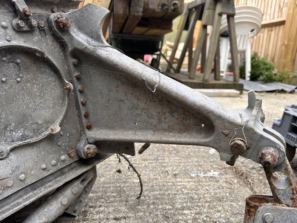

-
1/32 Westland Whirlwind
GunnarO replied to JeroenPeters's topic in LSM 1/35 and Larger Work In Progress
The glycol tank is not missing, it's just relocated. The Peregrine had electric starter on the rear left side of the engine, no Coffman starter. However, the Whirlwind did have a sort of Coffman starter. In the rear fuselage it was a signaling device that was used to shoot out signal flares that was identical to a Coffman starter.
-
1/32 Westland Whirlwind
GunnarO replied to JeroenPeters's topic in LSM 1/35 and Larger Work In Progress
Look forward to see the results, hope I can help with some information and guidance.
-
1/32 Westland Whirlwind
GunnarO replied to JeroenPeters's topic in LSM 1/35 and Larger Work In Progress
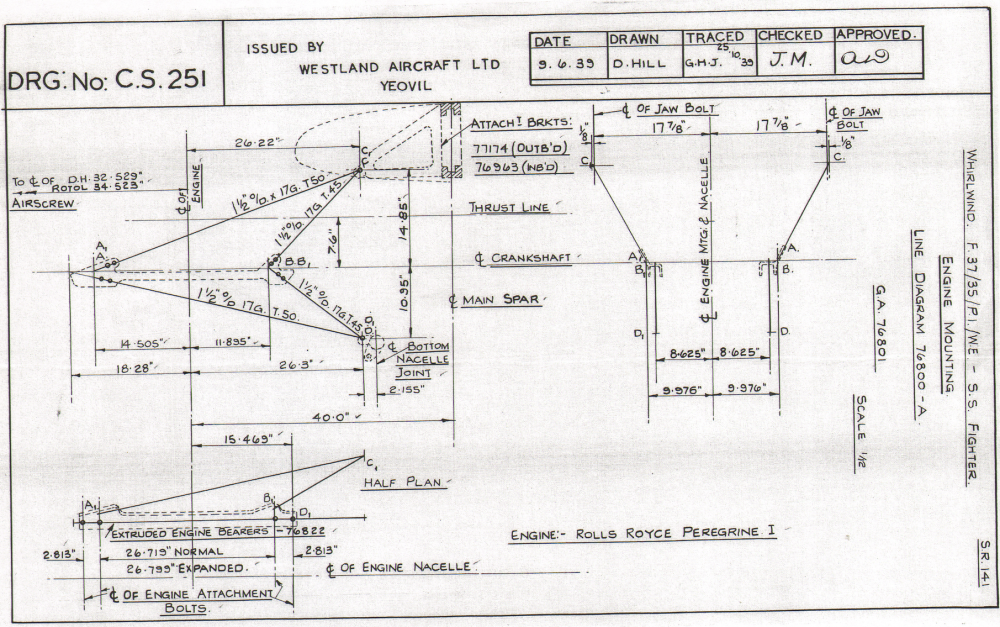
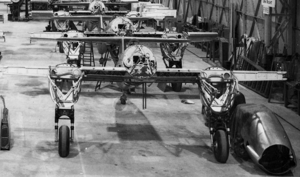
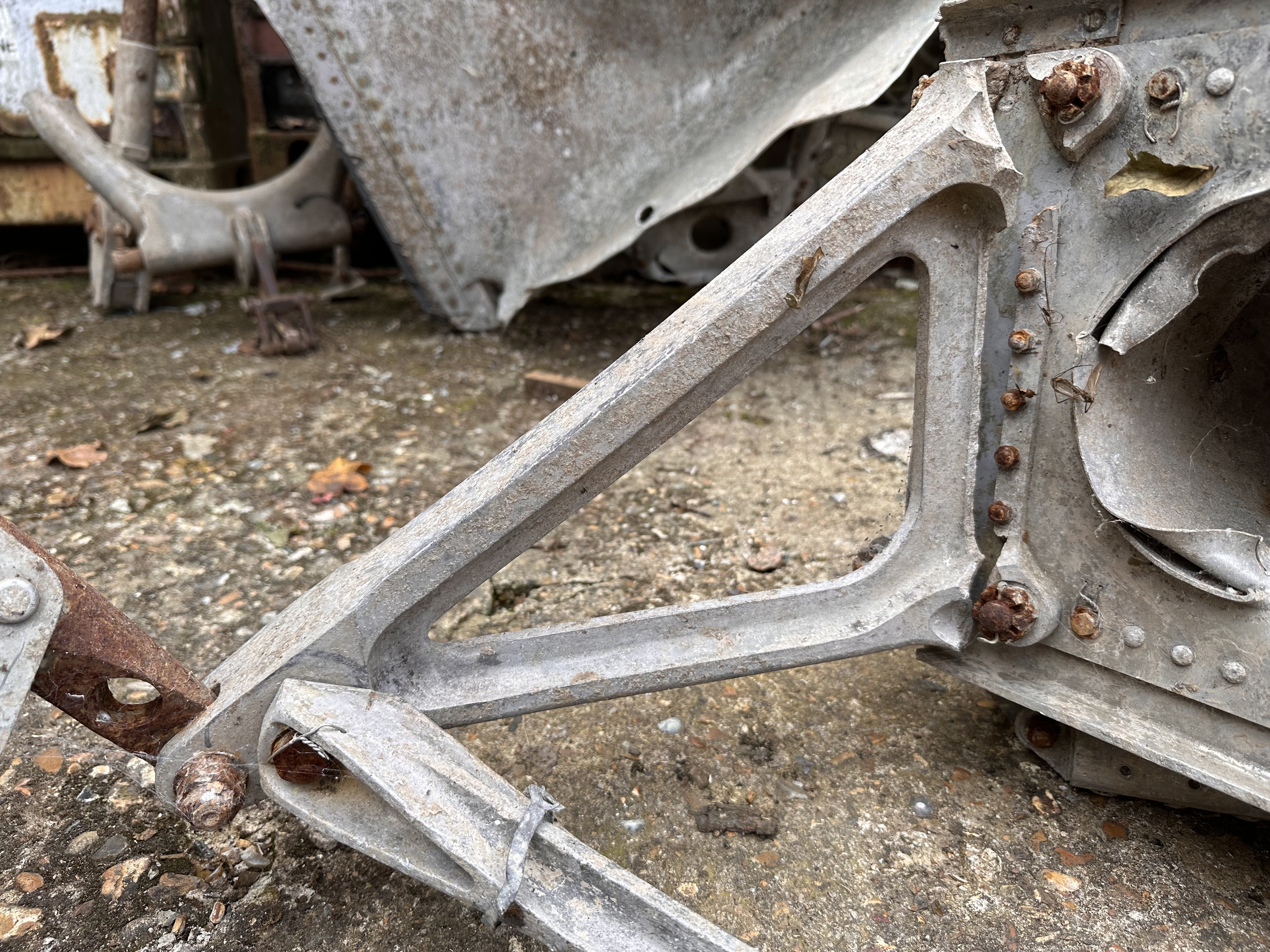
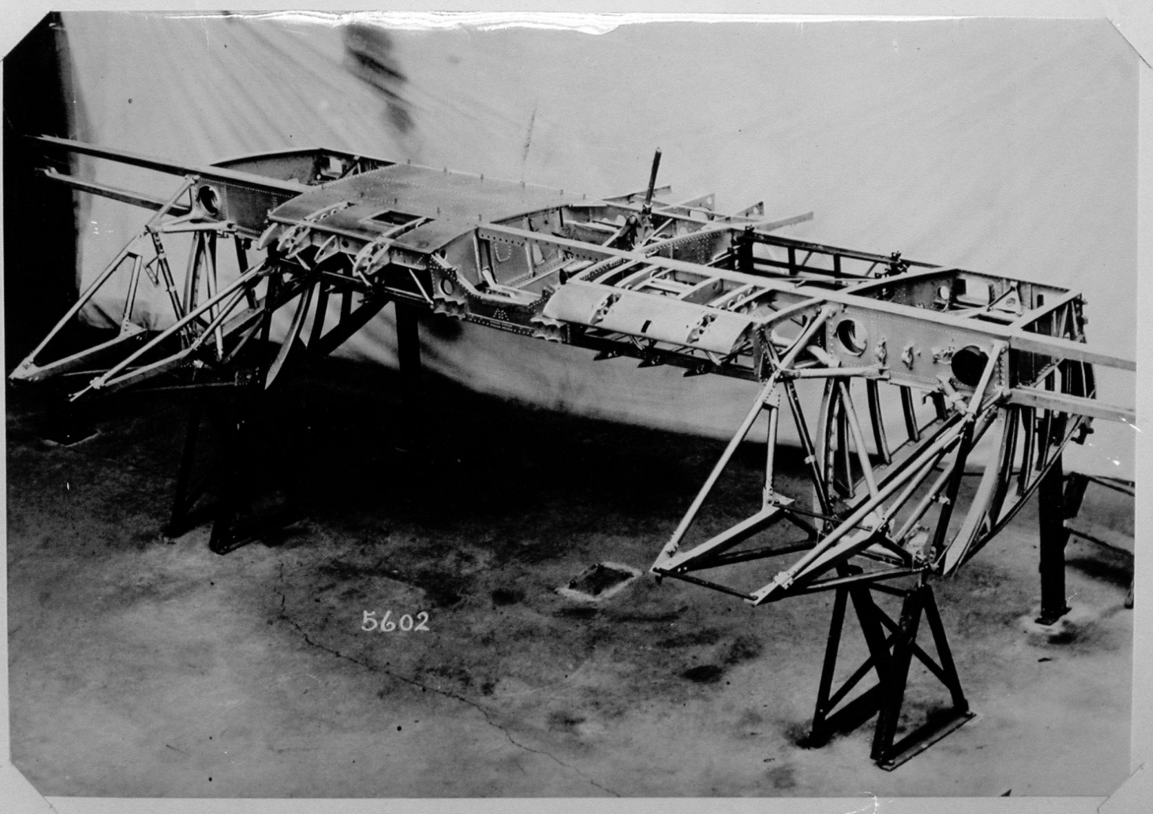
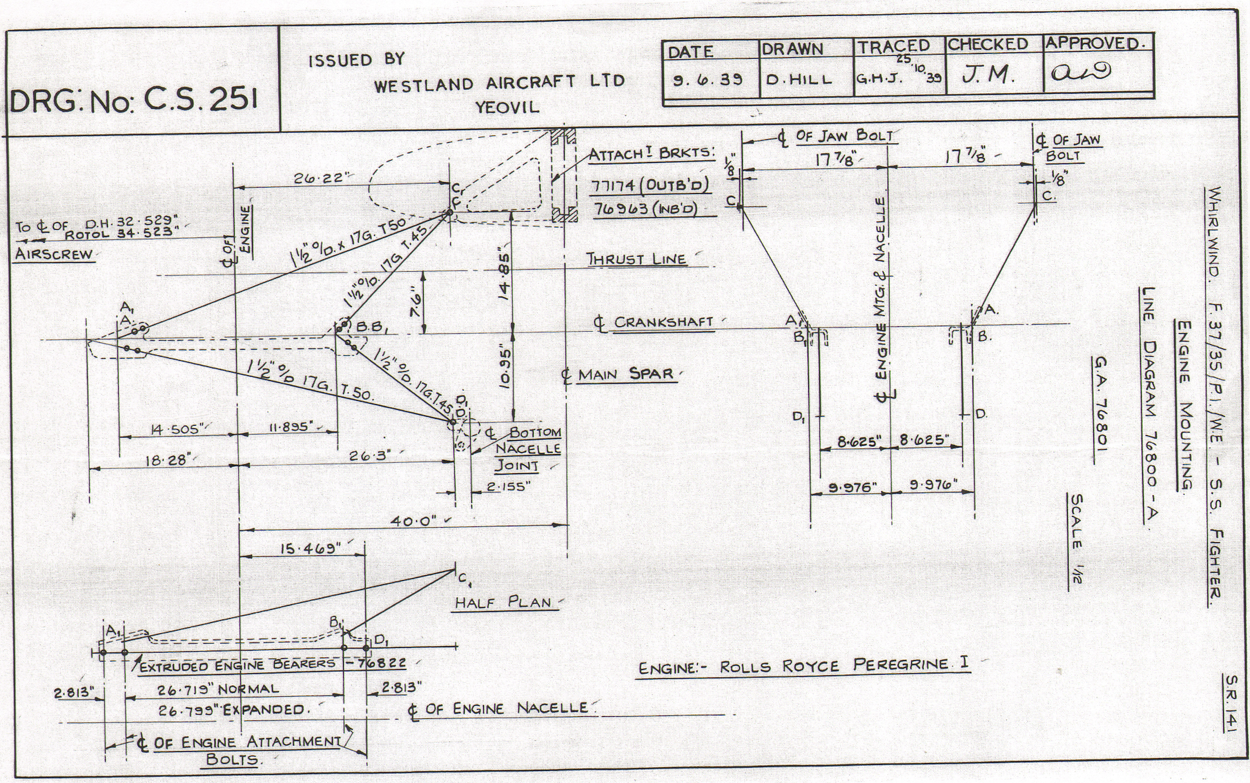
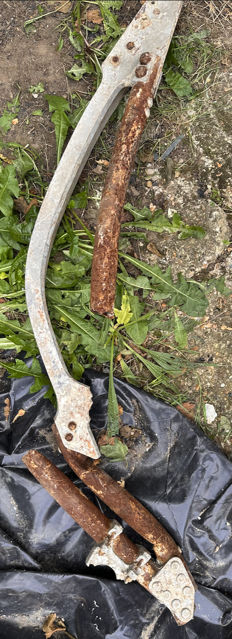
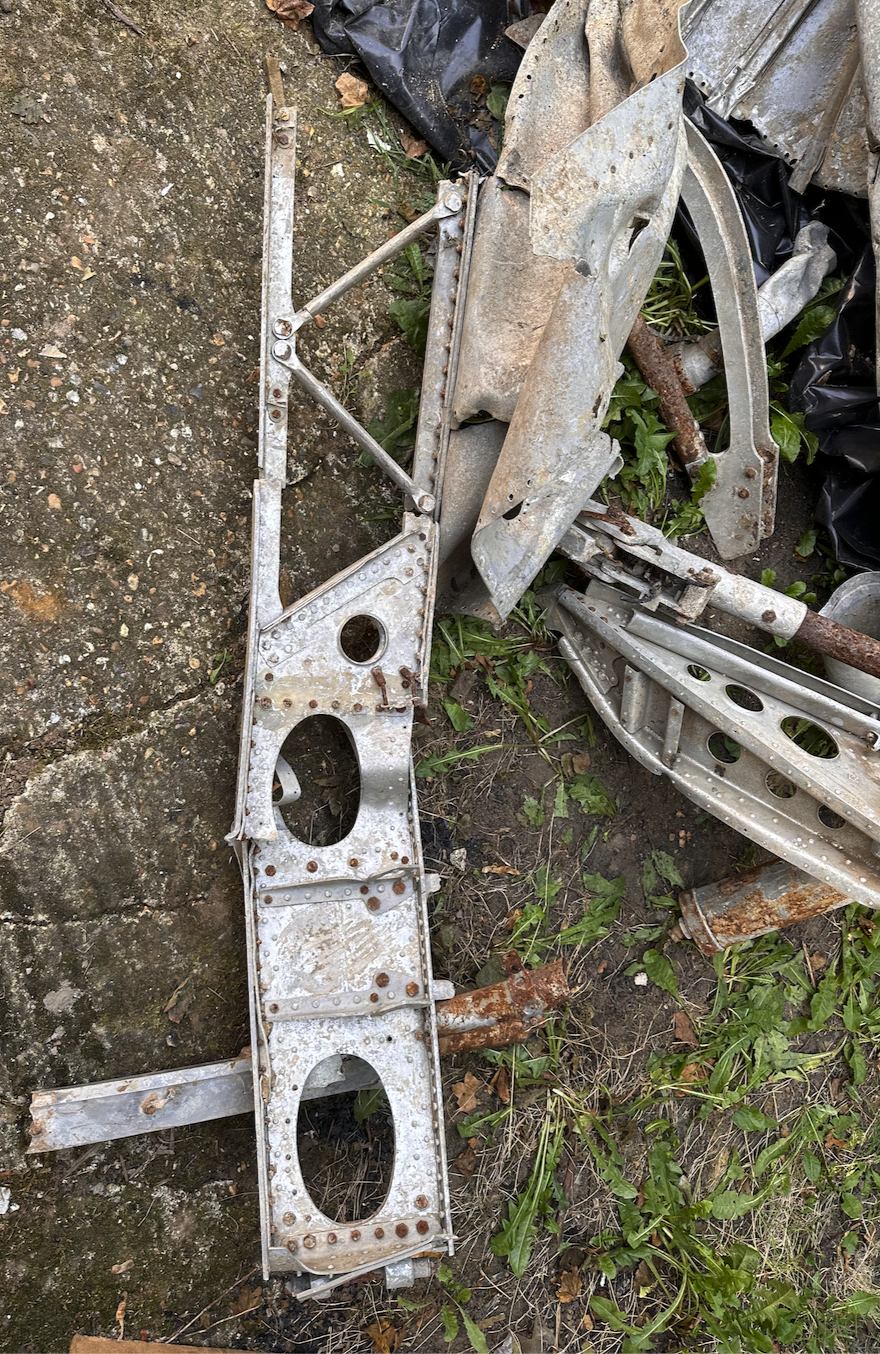
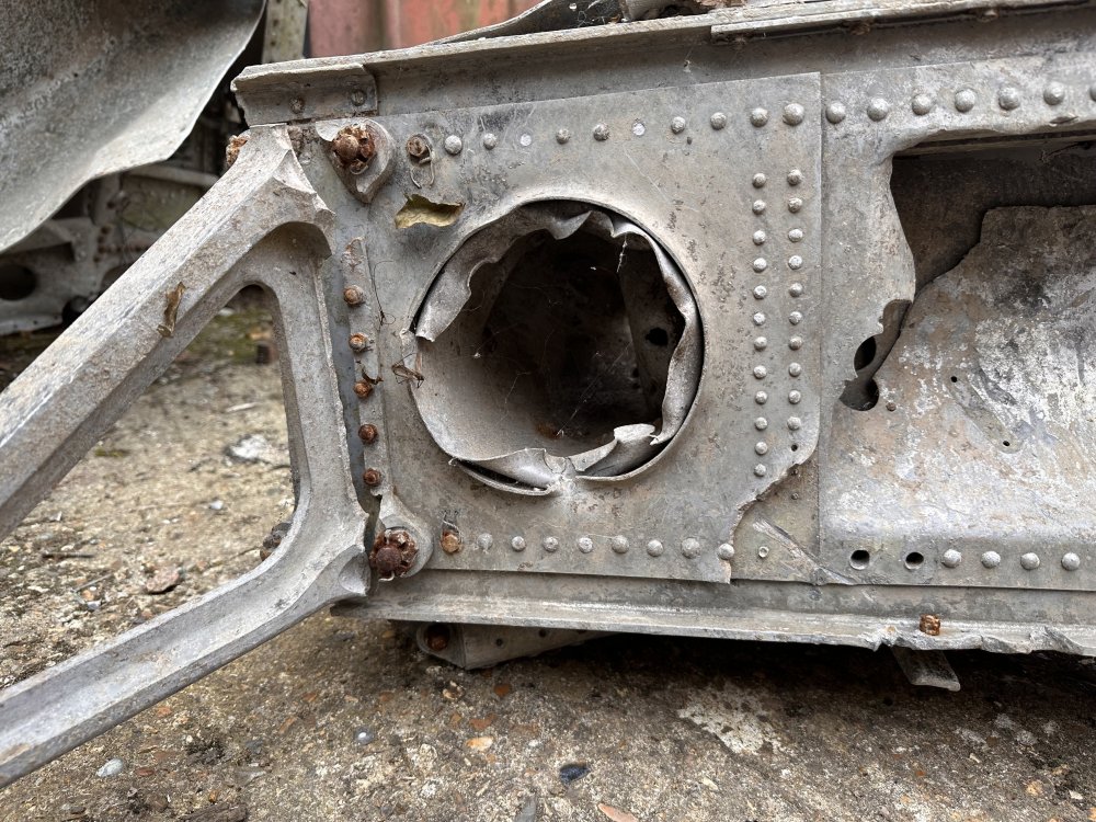
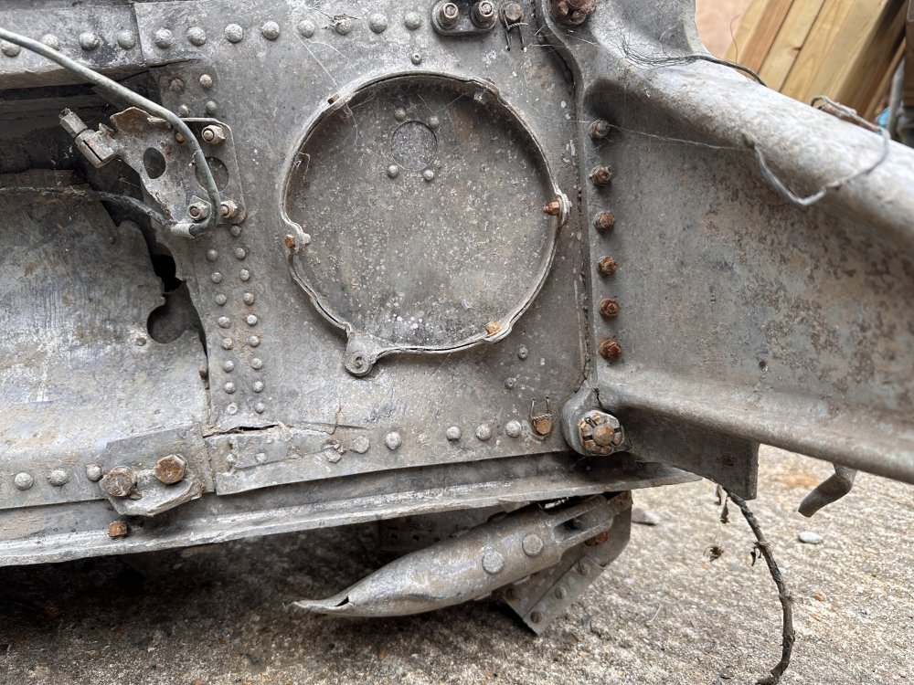
Some references for the engine bearers, and some bent ones. Wreckage images from P6966 crash.