

Nick_Karatzides
-
Posts
179 -
Joined
Content Type
Profiles
Forums
Events
Gallery
Posts posted by Nick_Karatzides
-
-
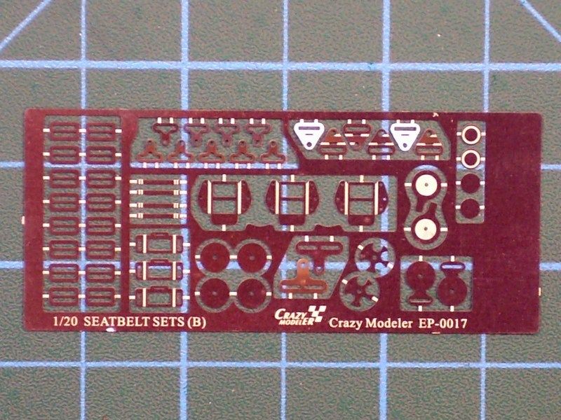
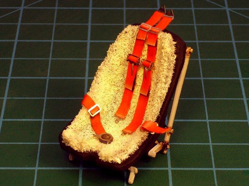
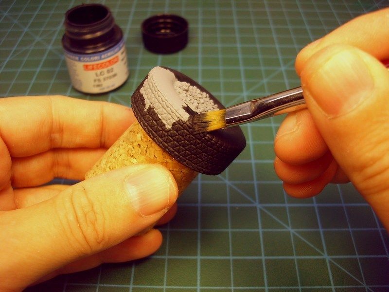
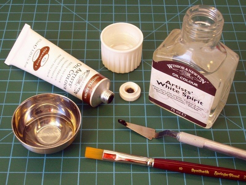
To form a complete pilot’s seat, I used the “EP-0017 seatbelts” photoetched set by Crazy Modeler, under 1/20 scale. The seatbelts got paint with red color - although they looked like khaki color in B&W pictures of the actual gyro - so as to make sharp & nice looking contrast with the previously mentioned (into CHAPTER IV) wool flock blanket covered seat.
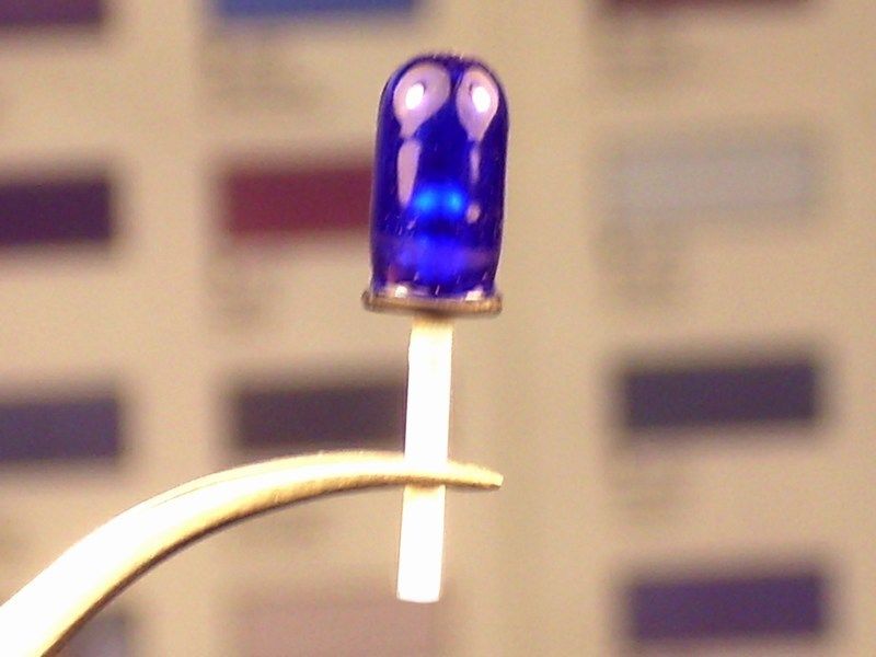
Some additional items, also designed from scratch and later 3D printed under 1/18 scale, such as fire extinguisher, 20 lt fuel canisters, wheel chocks and taxiway light unit, got also some paint & dirt effects. Maybe is not easily vissible, but there is also a bulb inside the blue cover of the taxiway light unit. Unfortunatelly, its hard to discern behind the dark blue glass

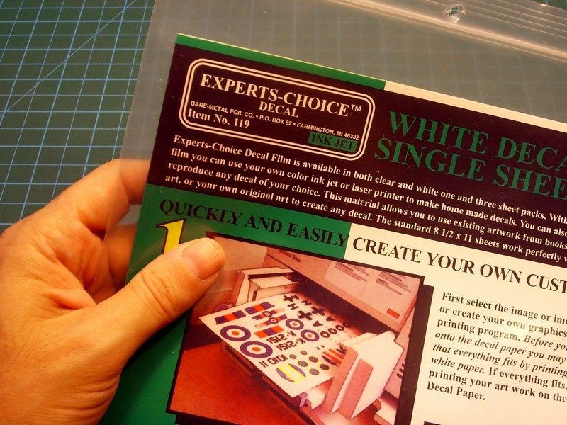
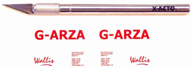
To replicate the G-ARZA callsign & Wallis logo on autogyro’s tail rudder and a few more written details on fire extinguisher & fuel canisters, I had to create some right-in-scale custom water slide decals. To do so, I used the A4 sized printable “Experts Choice Decal” film by BMF - Bare Metal Foil Co. The decal film is available in both clear and white one. The decal film can be printed on color inkjet printers, on LASER printers or a color photocopier to reproduce any digital image. Keep in mind that the inkjet decal film is intended for use with inkjet printers only. For photocopiers and LASER printers, the LASER decal film should be the best choice. After designing the images on Corel & rescaling on right dimensions, LASER printing the water slide decals on film and thereafter applying decals on model, I used a soft brush to apply a light coat of Microscale MicroSol to soften the decal and allow it to become part of the surface.
As soon as the water slide decals were dry, an acrylic gloss coat applied to seal the result so far. Once the acrylic gloss coat has cured, I tried to wash the paint by brushing artists grade oil paints with a broad, soft brush and spread the paint around until the desired colour density is achieved. At this point the oils would be workable for several hours. With a broad, soft, clean and completely dry paint brush, I draged over the oil paint, leaving dirt streaks. As the brush picked up the paint, I wiped it off on a clean, lint free cloth and continue process. “Lint free is the key phrase, as any speck of lint would adhere to the oil paint and destroy the finish. The beauty of this technique is that you can clean the oils off and try again if you goof up. I used a clean cloth and turpenoid paint thinner - not lacquer thinner - to wipe clean any mistakes and start over again. Some of the wash mixture is re-applied and the wash being wiped completely out of the narrow points.
-
1/18 may be an odd scale, but for a subject this small, it needs to be LARGE scale..
Size does matter
-
For WIP click HERE. Advices, ideas & constructive feedback on how I can improve my future models, is always welcome.


-
 1
1
-
-
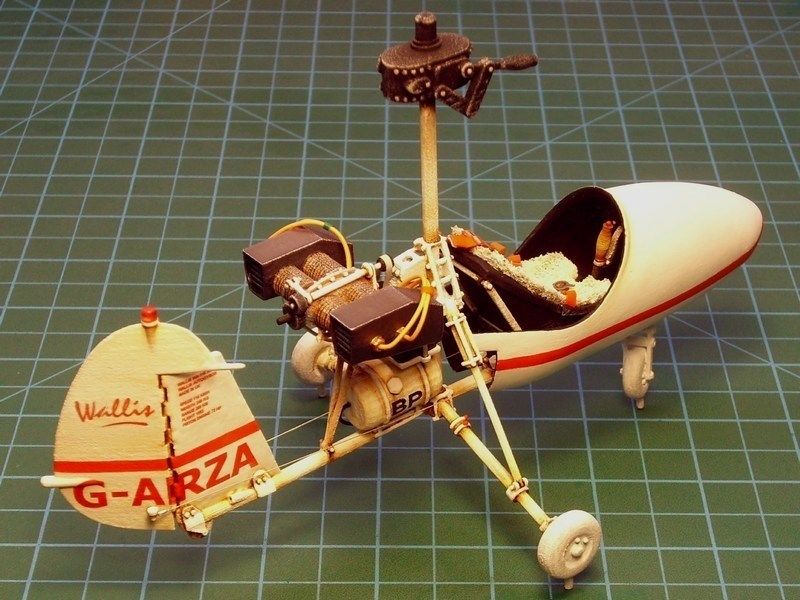
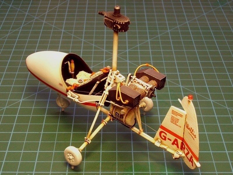
CHAPTER V - Applying paint, wash & weather effects
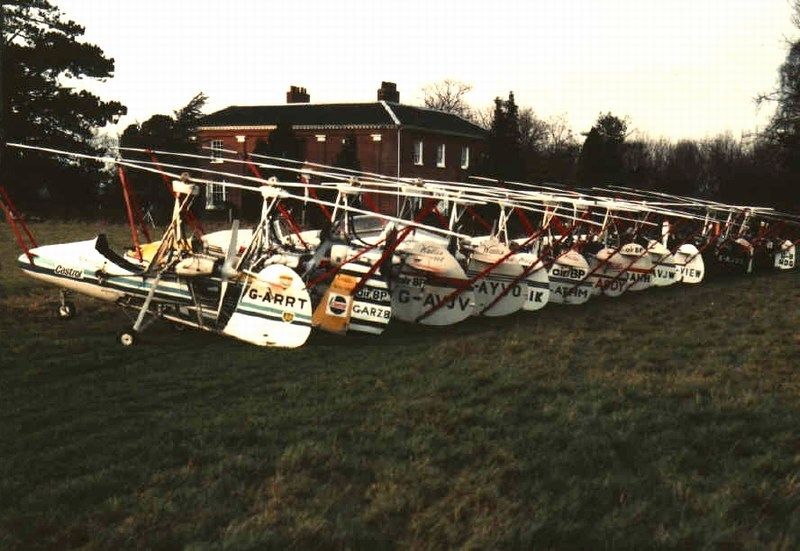
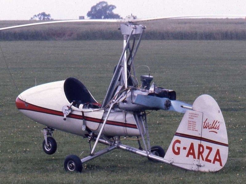
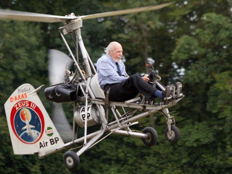
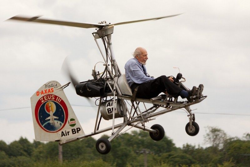
Before dealing with this project, I had the impression that all Wallis autogyros, were all same - at least identical. The fact that each one of them is not a product of a factory assembling line but the result of custom hand work, shows that there are plenty of differences between them - obvious differences or just small details identified after careful observation. The autogyro represented here, is the s/n G-ARZA, one of the five first built WA-116s, typed as "Wallis WA-116/Mc Srs.1" (the “Mc” means McCulloch engine and the “Srs.1” goes for series 1). The three of these first five Wallis autogyros were produced on behalf of British Army Air Corps for further evaluation and had no cabin cover. After a brief military carreer, these three Wallis WA-116/Mc Srs.1 remodified, repainted and received new civilian callsign reguster. One of them, was destined to become very famous as "Little Nellie" after appearing in the 1967 James Bond film “You Only Live Twice” movie. Research based on the published files & info, shows that the serial numbers of these first built "Srs.1" are the following:- G-ARRT was the first Beagle Aircraft built prototype, first flown on 2 August 1961 at Shoreham. Aerodynamic cabin cover added later.
- XR942 initially built on behalf of British Army Air Corps and later renamed to G-ARZA. Aerodynamic cabin cover & beacon lights on rudder fin added later.
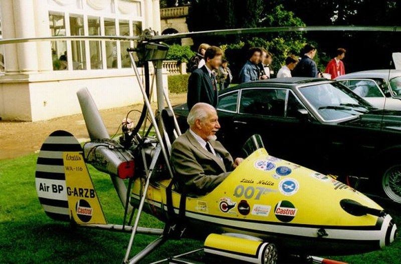
- XR943 initially built on behalf of British Army Air Corps and later renamed to G-ARZB. Aerodynamic cabin cover & dummy rocket launchers added later to become the widely known 007 James Bond’s "Little Nellie".
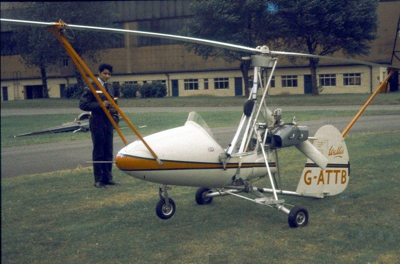
- XR944 initially built on behalf of British Army Air Corps and later renamed to G-ATTB. Aerodynamic cabin cover and longer main rotor blades added later.
- G-AXAS was the last built "Wallis WA-116/Mc Srs.1" and was Ken's favorite, since he was usually demo flying with it at Reymerston Hall Dereham, UK until his last days. The tail rudder fin was replaced on 1986, by a Wallis WA-122 spare part.
My goal is to paint the scheme of the G-ARZA, dressed up with it's new civilian colours, as appeared at EGBK Sywell, UK during the PFA Rally, back in 1973. Keep in mind that the specific autogyro, was initially built for military use, registered as XR942 and painted dark olive with official British Army markings - as seen at EGKB Biggin Hill, UK during the Biggin Hill Air Fair, back in 1964.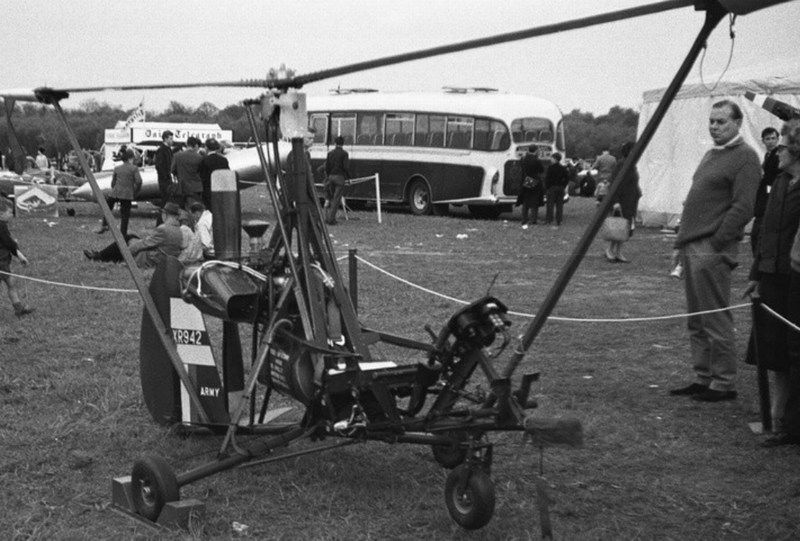
Model parts were washed with liquid soap and warm water to disappear leaving oil traces, fingertips etc and prepared for painting process. When it comes to apply paint on a scale model, I usually have the following two available options:- Paint the individual parts first and assemble the scale model later and
- Assemble the scale model parts first and paint the overall built model later.
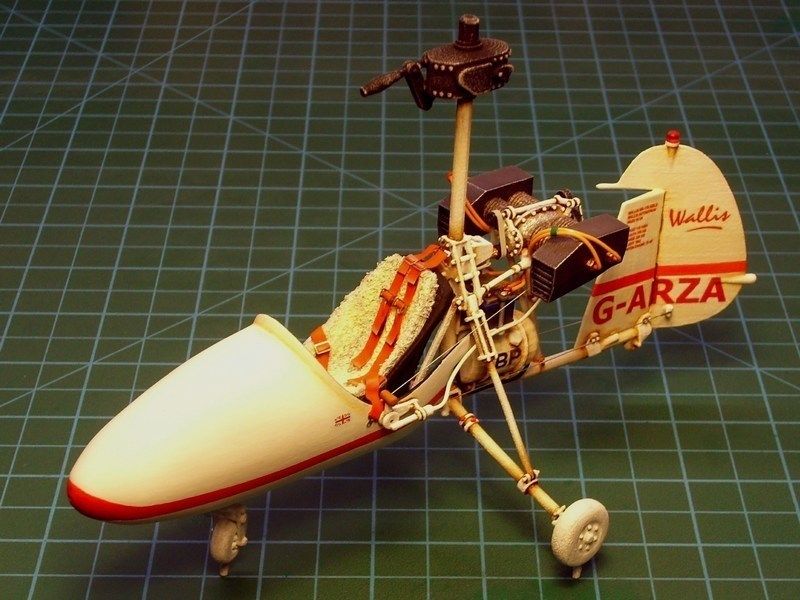
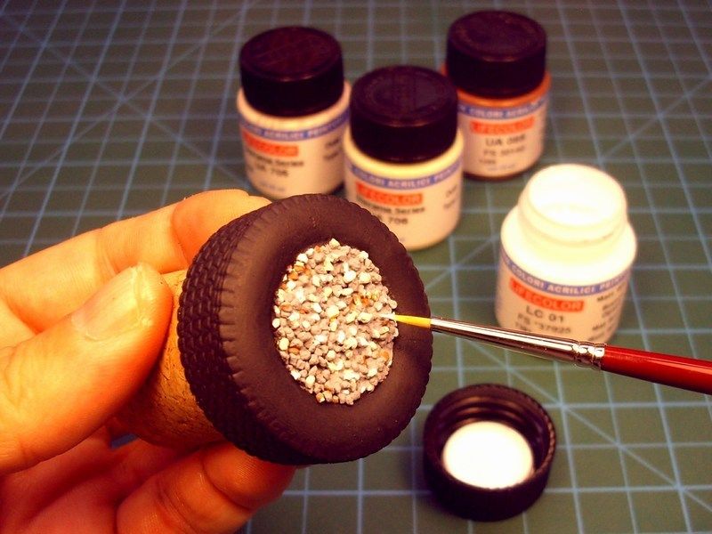
Since I designed this 1/18 scale Wallis WA-116 Agile autogyro in such way to look like a kit instead of 3D printing it as a fully built model, the first option seemed as more appropriate and would certainly make my job much easier. After preparing the engine’s basic elements, connecting electric cables and oil or fuel lines, the aft part consists of the tail boom & rudder fin structure, the McCulloch 4318A engine and the transmission components etc painted by using fine brush. The front part consists of the cabin aerodynamic cover & flight controls, airbrushed with with Life Color LC01 Matt White FS37925 acrylic paint for exterior and Life Color LC02 Matt Black FS37038 for interior. The red stripe on aerodynamic cover and tail fin, painted with Life Color LC06 Matt Red FS31302.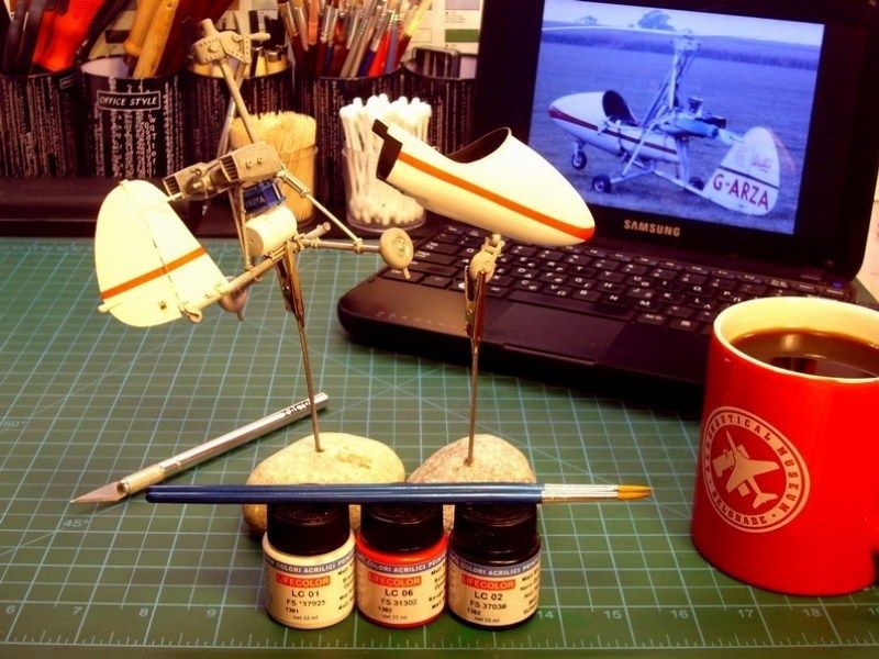
-
What an inspirational build. If you want to mould and cast this, I'd like to build this too......
@ James H,
All the projects I have built (already printed or still CAD files at the moment), including the 1/18 scale Instytucie Szybownictwa IS-A Salamandra 53 scratchbuild model previously presented in forum, are designed in such way to ensure that anything can be printed as kit and combined together to become a complete scale model. Nevertheless, because scale modeling is just an enjoyable hobby for me and because my main profession prevents me to engage in other activity, I am not interested for the moment to become a professional modeler and sell.
-
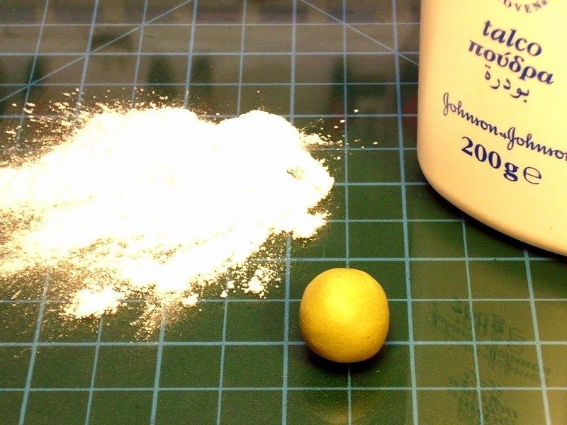
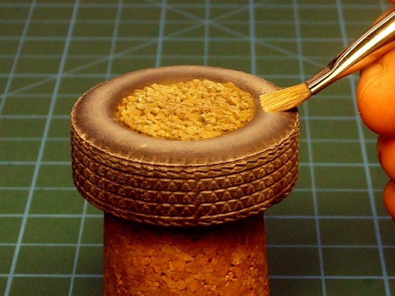
CHAPTER IV - Wool flock covered seat
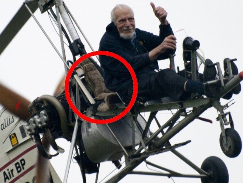
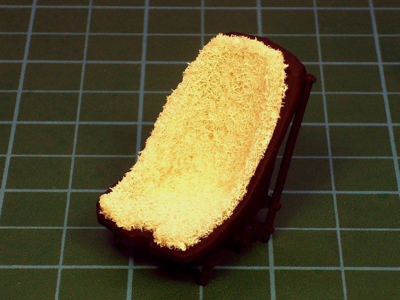
While studing on Wallis autogyros photos, I noticed that Ken had covered the Wallis WA-122 G-BGGW passenger's seat with wool flock fiber stuff. To be honest, I 've never seen any of the Wallis WA-116 autogyros having seats covered with this way, but I thought it was a good idea to replicate under scale and maybe possible to have happened in real gyro.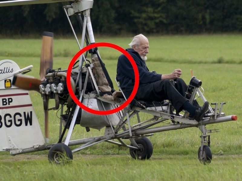
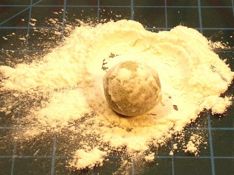
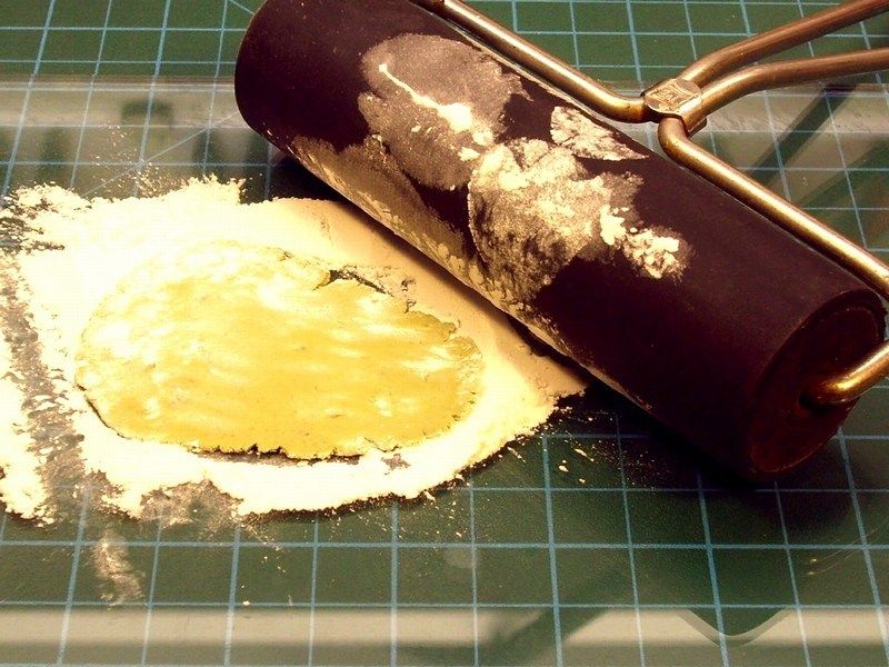
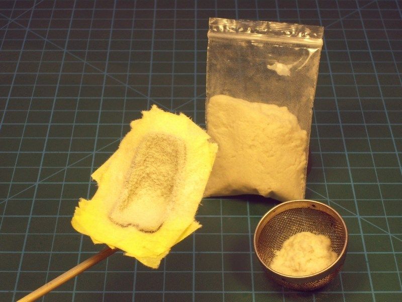
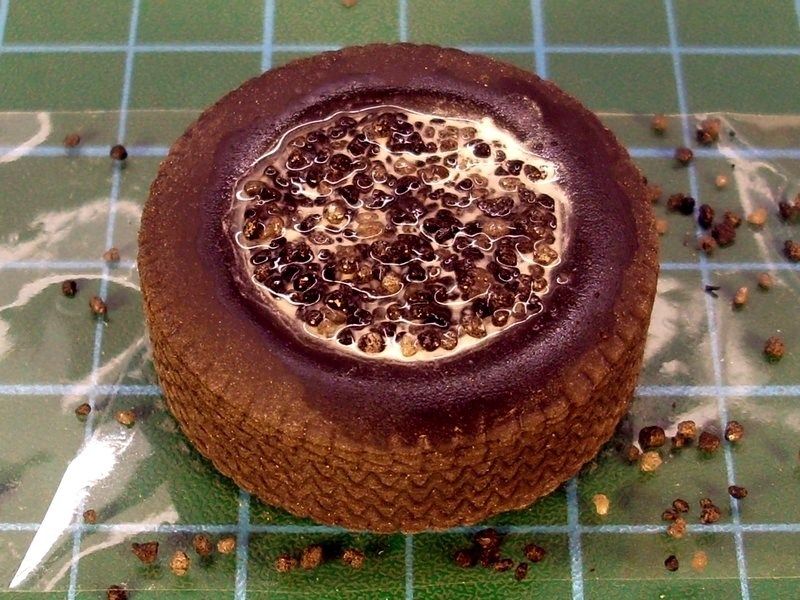
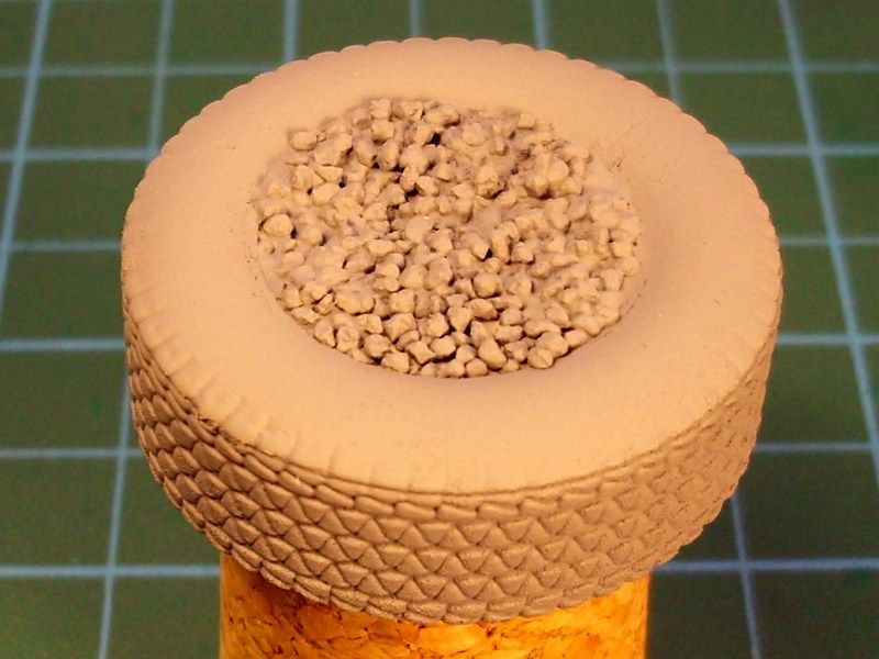
Using a small amount of Milliput putty, I made a small ball, dust it with talcum powder and pressed it against the working bench with a roller until it becomes about 0.5mm thin. The use of talcum powder is necessary to avoid Milliput sticking on roller or fingers and get easier to handle without tearing to pieces. While Milliput putty was still soft, I cut it into shape and placed it on pilot's seat, to form into a right to scale blanket cover.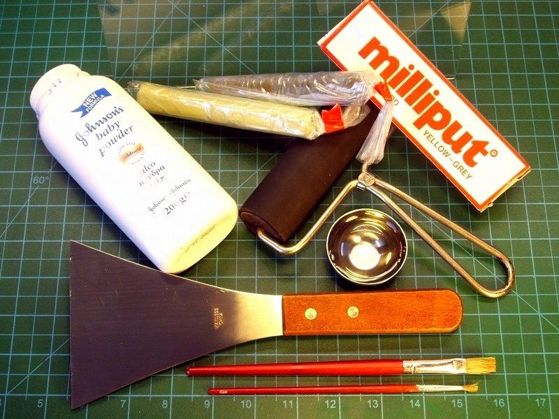
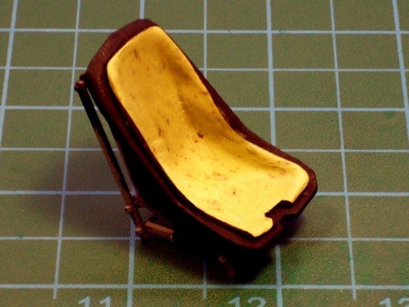
Then, seat covered with masking tape in such way to leave only the Milliput blanket area vissible. To recreate the seat cover, I used the #KF-00017 flocking powder product by KA Models, which is commonly used by scale car modelers to represent carpets. As you can see in the following photos, the flocking powder sprinkled through a sieve, over the Milliput blanket. When it looked OK to me, the powder secured in place, by airbrushing hairspray over the result.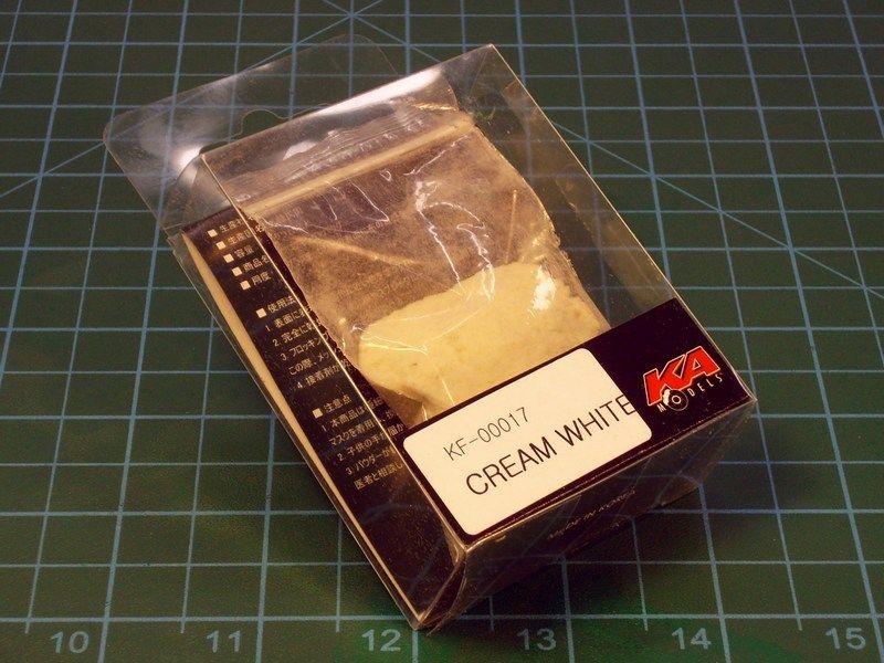
-
CHAPTER III - Attempting to join the basic parts
As soon as the individual scale model’s parts were already produced, cleaned & dry fit tested, I had to assemble everything as one piece, without damaging the frame construction. The plan is to assemble all model’s parts first, sand if required and later apply paint and weathering effects as a final touch. During assembling process, everything was secured in place & glued with CA liquid adhesive superglue, which does bonds in only few seconds, reaches extremely strength at room temperature and it is suitable for materials such as wood, rubber, plastic, metal, ceramics, leather, marble, polyethylene, polypropylene, teflon etc. Some tiny gaps were filled with putty, applied with an old brush. As soon as the joints were securely glued with CA superglue and later filled with putty on tiny gaps, it was carefully sanded with nail files & sanding sponge block. When it looked OK to me, the whole model was sprayed over with Humbrol acrylic primer to spot any mistakes and placed into a box to wait the final paint applying.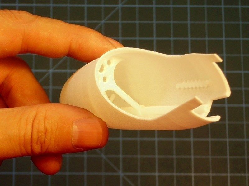
After my sweetheart wife (aka “4-star General in home” & “family's financial director”) conducted a strict quality control and result evaluation, she smiled & proudly signaled green light for further building & painting. Each section was dry fit tested to ensure that anything can be combined together as one piece, the parts forwarded for assembly.
-
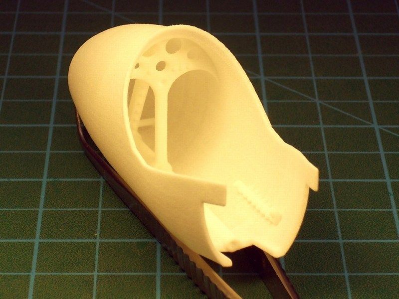
CHAPTER II - Converting Mbytes into actual model parts
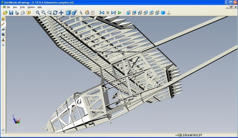
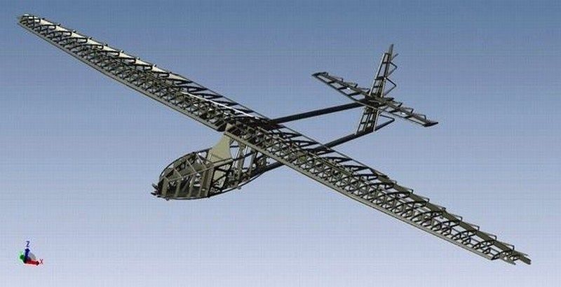
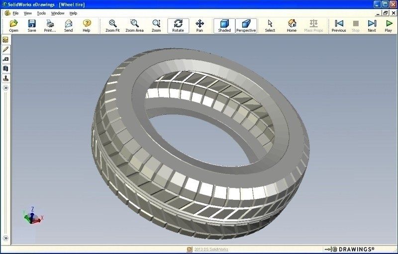
Before start building a new scale model, I always try to study as much as possible the object of construction. Any available technical manuals and detailed walkaround photos, always help during model building process. As previously described into my previous WIP (feel free to have a look on the 1/18 scale Instytut Szybownictwa IS-A Salamandra 53 scratchbuild model already uploaded into the present forum), the plan is to design a CAD file and then print it, on a 3D replicator. This method, helps a lot and gives the opportunity to scratchbuild almost anything, under any scale, within only few minutes. The 3D printing technology introduction into scale modelling and free access to the average modeller is a great evolution in the hobby and a creative tool that helps us to build better and more realistic models. Certainly the new technologies and gadget tools in the hands of talented enthusiasts open new horizons and provide wide potentials on scale model building.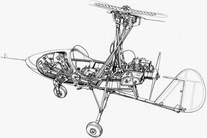
It took a couple of hours of CAD work on my laptop, to 3D design, scale into correct 1/18 size and then digitally cut the autogyro’s compartments into virtual pieces, having always in mind that the later printed parts, should perfectly fit and finally become a fine scale model. And voilà, we have a winner! A new Wallis WA-116 Agile autogyro virtual model, is ready to be forwarded to the 3D printer and become an actual object under 1/18 scale, within short time.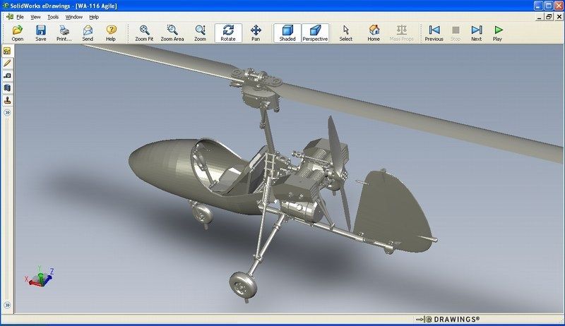
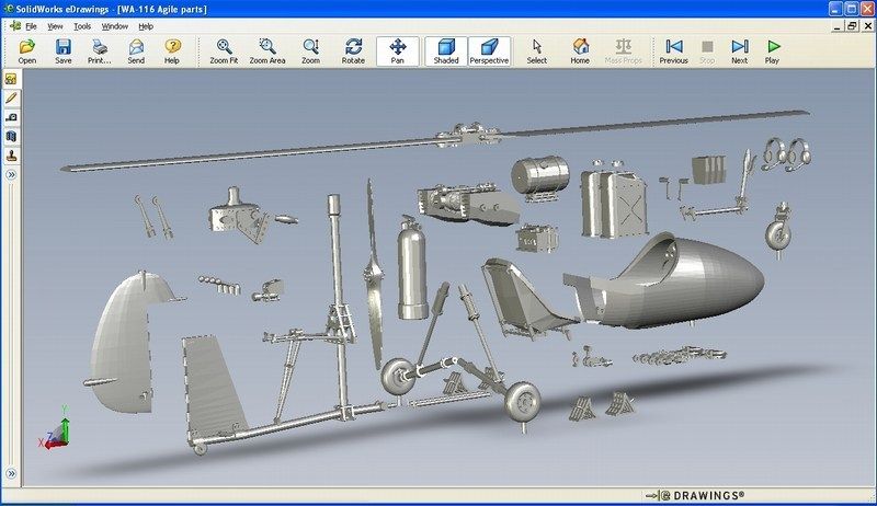
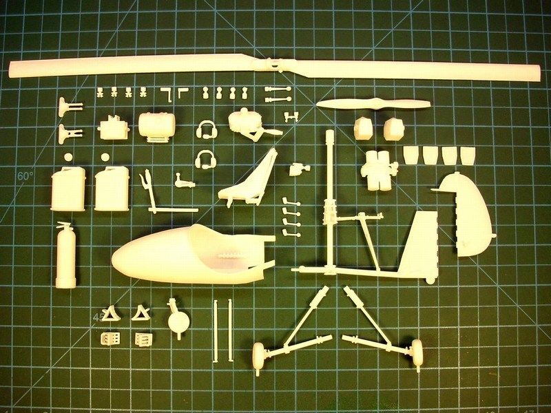
After building the 3D model and double check for possible mistakes, I saved it as a digital file and forward it on a 3D printer to start generating the individual parts of the autogyro scale model. Shortly thereafter, the printing proceeding outcome pleased me, while watching the Mbytes, magically converting into actual items. Once again, the 3D printing technology on scale modeler’s service. As seen in the following pictures, as soon as the produced parts were cleaned, I checked for broken parts & imperfections. The model now consists of only a few parts, found into basic frame sections. Some additional details such as supporting rods, control bars & wires etc made of styrene, will be later added.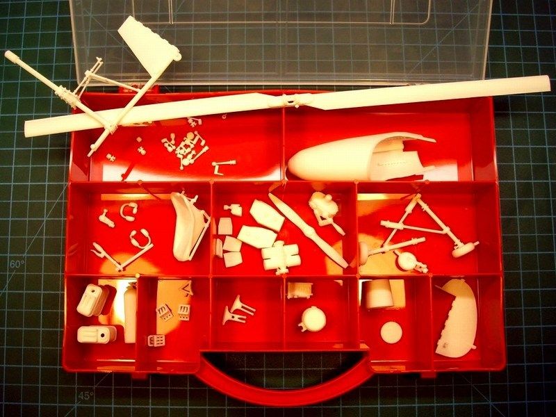
-
Please tell me he will be part of the build too!
I had in mind to also add the following 3D printed 1/18 scale figure which seems to pose nice, but I have two problems.
- The figure seems to be little overweight comparing to Ken,
- I 've never tried to paint a figure and not willing to risk now
-
CHAPTER I - Little Nellie only lives twice
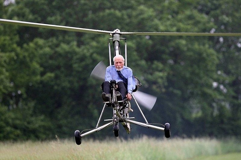
The autogyro differs from the helicopter in that it has a upwards thrusting propeller and a second prop to drive the forward. The gyro's upward’s prop lifts air much the same as a glider. The autogyro's roots go back in 1921 when it was invented by Juan De la Cierva, when he was looking to develop a light and fast bomber for the Spanish military. Development continued over the years and during WWII both Germany and Japan built their own autogyro versions. Wallis Autogyros Ltd was founded in 1961 by RAF Wing Commander Kenneth Horatio Wallis and has produced an extremely wide range of special purpose autogyros. The Wallis WA-116 Agile created by Wallis runs on the same principles as that built by Cierva but it much smaller and more nimble. The first prototype, registered G-ARRT, was a single seater ultralight autogyro first flown on 2 August 1961 and being developed with different models over the years, with such uses as military training, police reconnaissance and survey work. It could lift twice its own weight, fly 210 km/h and rapidly climb to 4100 m, even though it weighed 110 kg. This aircraft could take off in 30 yards of space at a minimum speed of approximately 20 km/h. In 1962, five WA-116s were built by Beagle Aircraft at Shoreham, three of which were for evaluation by the British Army Air Corps.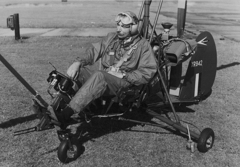
In 1966, one of the Beagle built WA-116s, registered G-ARZB (nicknamed as “Little Nellie”), was modified for use in the 1967 James Bond film “You Only Live Twice”. Few Wallis autogyros have been operated privately, with nearly all of them being used for research and demonstration flying by Ken Wallis himself.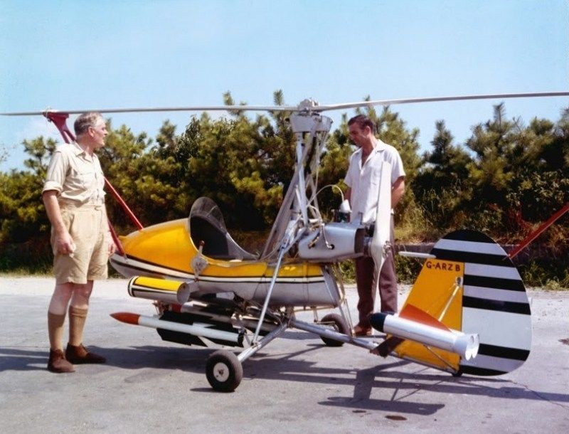
The Wallis WA-116 Agile was powered by a McCulloch Model 4318A four cylinder horizontally opposed air cooled engine, providing a top speed of 185 km/h and a range of 225 km. After building nine single seaters, the construction of a two seat variant the WA-116T was begun in 1969; Ken Wallis tested a four blade rotor and finally produced the WA-116F with which he won the closed circuit world record in 1974 in the 670.26 km category. Wallis autogyros have been powered by various types of engines, within the range 72 hp to 160 hp (the latter is used in the two seat Wallis WA-122) and have been employed for research programmes, including one promoted by Sperry Radar. In 1983 development of a production version, powered by a Weslake engine, was under way in association with Vinten Ltd. Intended primarily for paramilitary use, including policing and survey work, the definitive aircraft is due to be certificated in 1984. Ken Wallis, developed a number of improvements to the autogyro design, including the offset gimbal rotor head which gives the autogyro hands-off stability.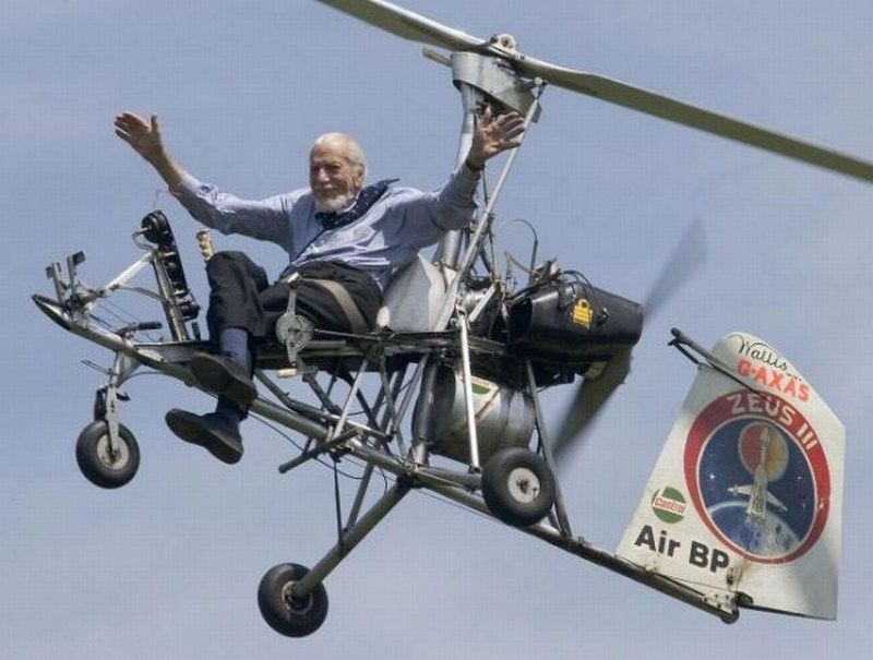
Technical data & general characteristics:- Type designation: Wallis WA-116 Agile,
- Manufacturer: Wallis Autogyros Limited,
- Usage: Reconnaissance / recreational autogyro,
- Crew: 1 pilot,
- Year of first construction: 1961,
- Year of first flight: 1962,
- Country of production: United Kingdom,
- Length: 11 ft (3.38 m),
- Height: 6 ft 1 in (1.85 m),
- Rotor diameter: 20 ft 4 in (6.20 m),
- Empty weight: 255 lb (116 kg),
- Gross weight: 550 lb (249 kg),
- Maximum speed: 100 mph (161 km/h),
- Rate of climb: 1071 ft/min (5.44 m/s),
- Service ceiling: 10000 ft (3048 m),
- Range: 130 miles (209 km),
- Flight endurance: 2.5 hours with 58 lb fuel,
- Powerplant: 1 x Wallis McCulloch 4318A piston engine, 54 KW (72 hp).
-
1/18 scale Wallis WA-116 Agile autogyro scratchbuild model
The following construction is a tribute to RAF Wing Commander Kenneth Horatio Wallis DSO MBE CEng FRAeS PhD, a pioneer gyrocopter aviator, who passed away early on Sunday morning, September 1st 2013. Ken was 97 years old. During the WWII, Wallis served in the Royal Air Force as Westland Lysander and Wellington pilot and flew 28 bomber missions over Germany. After the War, he flew the massive Convair B-36 and later involved in research and development, before retiring in 1964. He later became one of the leading exponents of autogyros and earned 34 world records, still holding eight of them at the time of his death. He was an inspiration to us all and we shall greatly miss him. A local hero and a national treasure.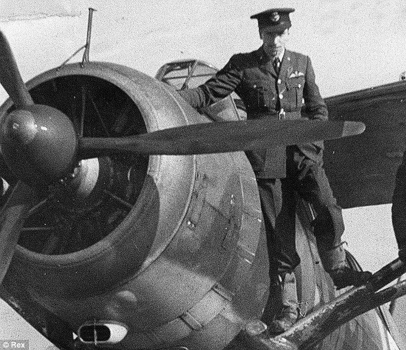
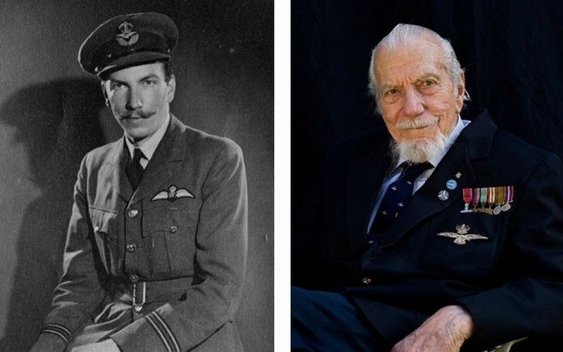
He was born on the 26th April 1916, at Ely in Cambridgeshire. With his father and uncle having built an aeroplane in 1908 to fly the channel in a competition that was eventually won by Louis Bleriot, Ken Wallis acquired an interest in practical mechanics at an early age and by the time he was eleven years old had built his own motorcycle. He eventually turned his attention to aviation following a flying demonstration he watched in 1936 of the Henri Mignet HM-14 Flying Flea / Pou Du Ciel.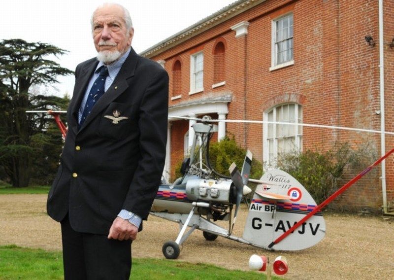
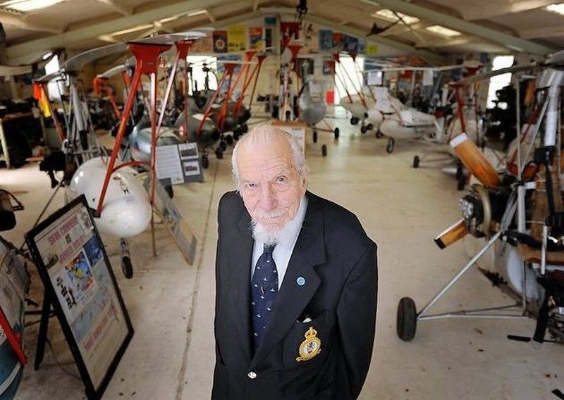
Ken will be greatly missed by the Flixton museum members. He was a frequent visitor, generous fundraiser and a great ambassador. In addition to the numerous professional institutions who welcomed Ken as a member and the vast number of clubs who regarded him with great respect and fondness, many ordinary people will also feel a loss in one way or another. Even a short chat with him left the individual feeling that it was something special and his warmth made them feel that he would remember them! Ken was recognised wherever he went. Admirers would soon gather and he would usually produce a small clipboard from a pocket, to sign and give away autographed postcards of him flying the “Little Nellie”. I am sure that many a childless adult has asked for a card to give to their “offspring”. Ken was inspirational, a great role model and possessed a rare old-world charm plus the impeccable manners of his age; all without a hint of grandeur. I am not alone in thinking that he was probably the grandfather figure we would all have liked to have had at some time. Norfolk was Ken’s home from 1963 and I venture to think he was appreciated by such a large part of its population that he was likely a close second to its most revered inhabitant: Horatio Nelson.
Goodbye Ken - our gyrocopter aviation hero and national treasure.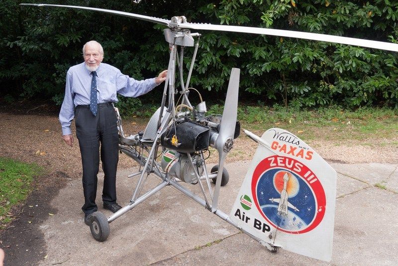
-
CHAPTER XI - Epilogue & aknowledgments
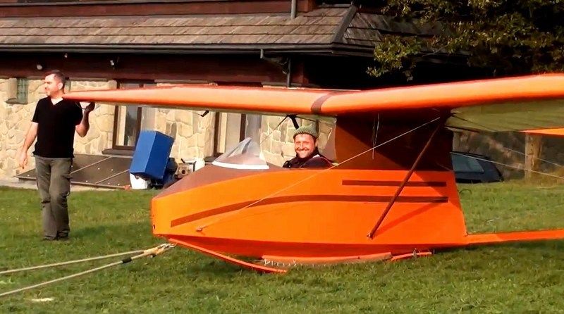
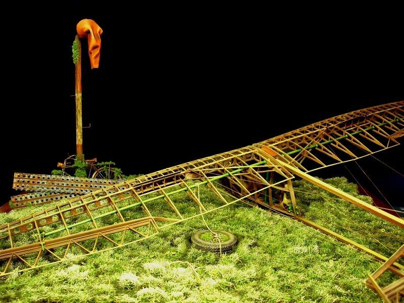
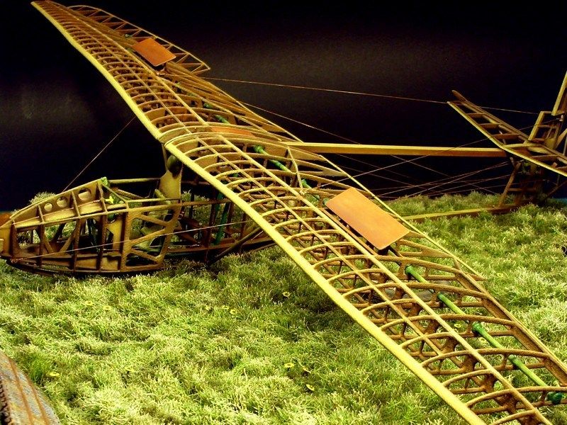
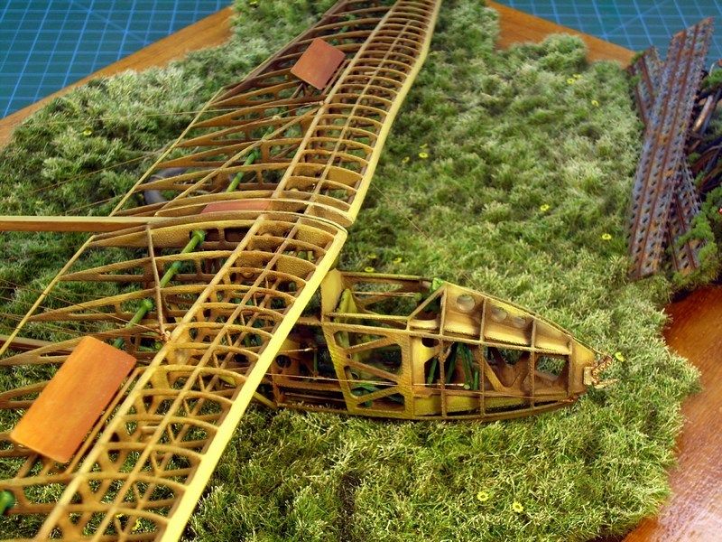
Although I had other plans at the beginning of this WIP, I was not really sure about the ending and especially the display base for the model. I changed my mind during the building process and finally decide to present as found in a small green grass covered airfield, now used by general aviation pilots for their weekend excursions, where the Salamandra glider is now resting tilted sideways, with one wingtip touching the ground and the other on air. A kind of wordless symbolism for the old fella who tirelessly offered training services to thousands aviators, weary lying on the ground but still turning wing high in the sky, where it belongs.
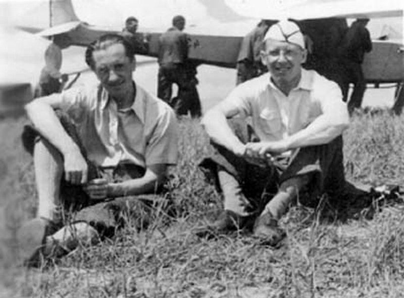
I ‘d like to share with you, a rare photograph. It takes us back to autumn of 1936, possibly in Lwow, Poland (now Lviv, Ukraine). The man with the hat (right), is Mr. Waclaw Czerwinski, one of the leading aircraft designers and head of the "WWS - Wojskowe Warsztaty Szybowcowe" (meaning “Military Gliding Workshops” in Polish language). The WWS-1 Salamandra glider (re-engineered as "Instytut Szybownictwa IS-A" after the WWII), was the first project which was created under his leadership during the mid 1930ies. The other man (left) is Mr. Tadeusz Chlipalski, the head engineer who established the plant for the gliders production in Bielsko Biala at south Poland.
It was a pleasant surprise to discover that an American guy named Scott J Grunewald found the model kit build interesting enough and dedicated an article on 3D printing related site. For more info, feel free to click HERE.
I would like to express my special thanks to:
- All fellow scale modelers, who have expressed their ideas through this forum and suggested solutions to technical issues encountered during this WIP.
- Mr. George Papadimitriou, owner of Hobby Gallery hobby shop and exclusive distributor for LifeColor & AK Interactive products in Greece, for his kind support and providing all the goodies I asked for - from A to Z.
- Mr. Nikolaos Kountouris, owner of MDC - Model Display Case store, who personally supervised the construction of the polished beechwood base after my request and made sure superior quality work.
- Spartan king Agesilaus, from whom I borrowed the cue "today, the prowess died", later rephrased by me as "today, the scratch building died", which became the main motto during this WIP presentation.
- My sweetheart “4-star General in home” wife, who actively participated in the project as an indispensable assistant, offering me relaxing neck massage while working on my bench.
Finally, for those who are interested to check more info & pics, feel free to have a look on our Anyuta 3D printed scale models products catalog. Wife as website operator & sales cordinator is always ready to answer customer questions regarding 3D printed scale model kit & diorama accessories products. Thank you all for following this thread and I hope you enjoyed reading this article. I’ll meet you soon, on my next WIP - possibly a 3D printed.one.
Regards,
Nick

- All fellow scale modelers, who have expressed their ideas through this forum and suggested solutions to technical issues encountered during this WIP.
-
CHAPTER X - Alles zusammen
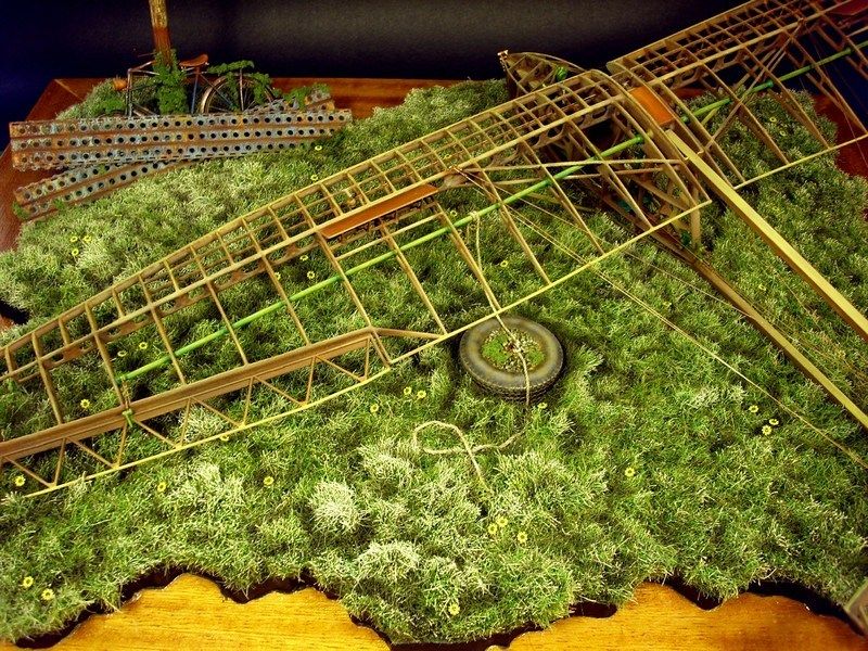
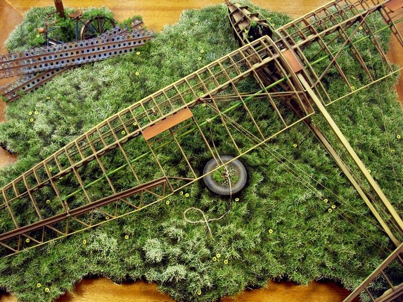
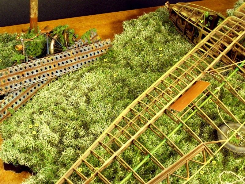
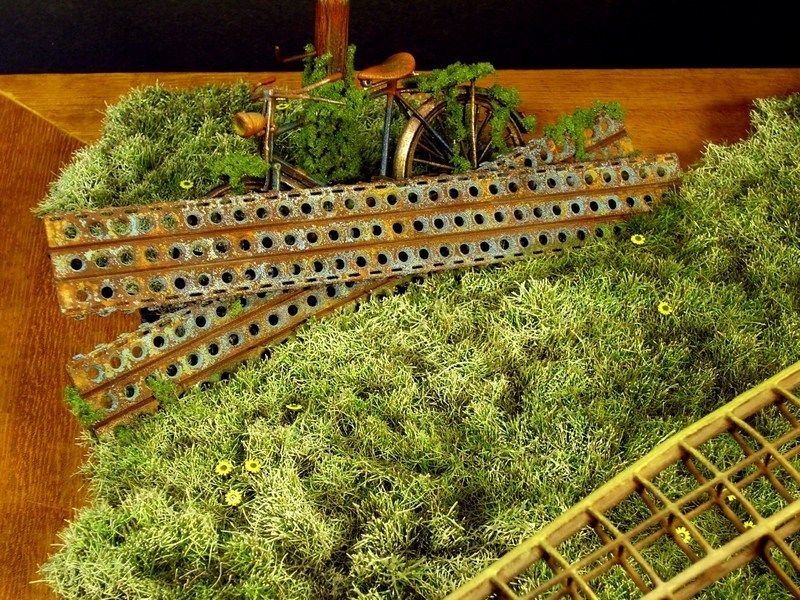
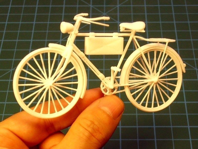
Daily watering was successful and the green grass is now high & wild enough on the field display base. At last, I had to conclude the "alles zusammen" final step. To assemble all individual parts in one scene, without damaging the glider's construction, the paint, the weathering and the rust & dust effects. That’s why I had to constantly monitor and try some dryfit tests all time, to ensure that I will not face any nasty surprises later. The windsock & the PSP plates, would be the first to be placed on the green grass display base and secured in place with hidden metal pins encased in the polished beechwood base through balsa wood sheet & glued with CA super glue. A last moment’s addition, an also 3D printed Fahrrad NSU bicycle model, painted in light blue colour (ammo box removed) not to remind it’s German military origin, placed against the windsock wood pole. Some rust effects also applied on bike’s metal frame.
Later, the improvised anchor made by concrete filled tire and the IS-A Salamandra glider model, both secured in place with hidden metal pins and glued on the ground with transparent silicon. Final details were added, such as the seat belts & buckles in cockpit, the clear windscreen, some extra dust & rust weathering effects on tension wires, etc. As soon as the result was OK for me, the scene sprayed over with Humbrol enamel mat coat, to seal the work so far and left it overnight to dry. The next day, I did a final inspection on result and set it up to shoot some pictures.
-
CHAPTER IX - Anchor & tie down
I 've noticed that pilots & airfield supporting personel, use a number of improvised anchors types, to tie down the gliders, ultralights or even single engine aircrafts such as Cessna 172s, especially when operating from some grass covered airfield, without any permanent anchorage points & lashing hoops installation on ground. These improvised anchors are made of concrete filled tires or cement block bricks also known as CMU - Concrete Masonry Units).
The tying is part of the checklist and therefore gliders, ultralights, gyrocopters etc, should remain tied and with wheel chocks instaled when grounded, because even the slightest breeze can cause to aircraft start rolling or flip the wings and hit wingtips on ground or worst. I've watched a video on YouTube, where a RAF's BAe Harrier GR.7 aircraft with no wheel chocks installed, began trundling because the wind gust, gone away from the apron and finally stopped on the grass, several meters away from the initial parking position. During this special "ride", the ground personnel just stood and watched the embarrassing view. Fortunately, no big damage caused that day, if we exclude some taxiway sign & the fence fell down and of course the groundcrew chief's pride. So, if this can happen on a mighty fighter jet that weighs 13 tons, why not also happen on a glider or an ultralight?
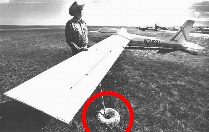
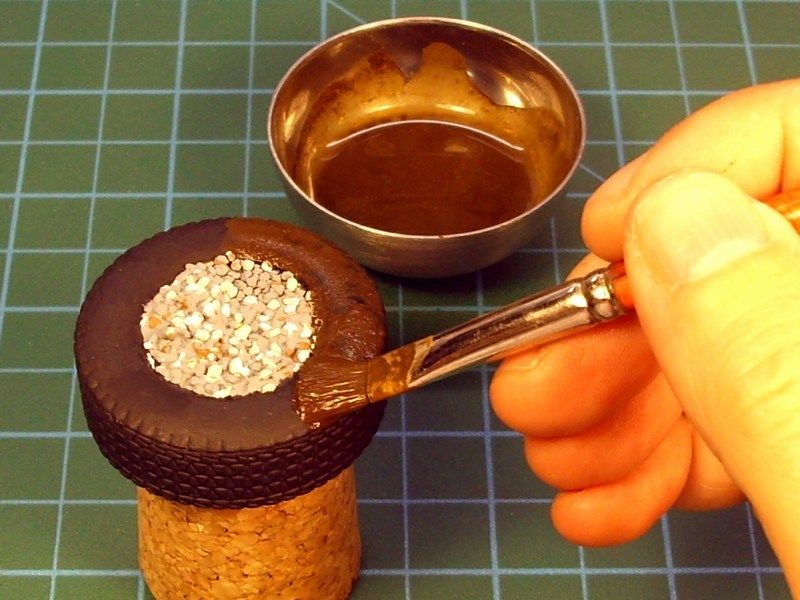
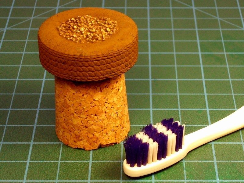
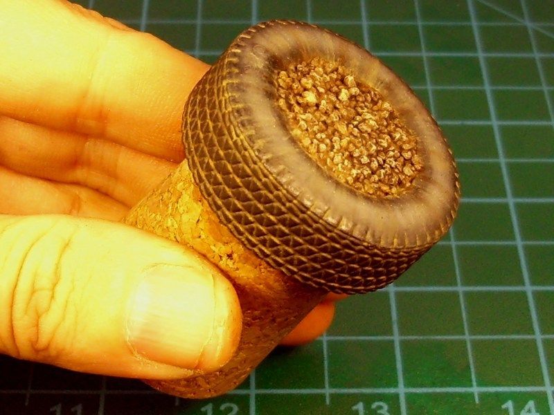
Building this improvised anchor made by concrete filled tire under scale, seemed OK to me. My first thought was to 3D print it and for this reason I actually, had just the right CAD model waiting for this purpose, in my laptop’s HD. Not having anything more to do that afternoon, I took my Mrs for a ride in town and some shopping at local Mall.
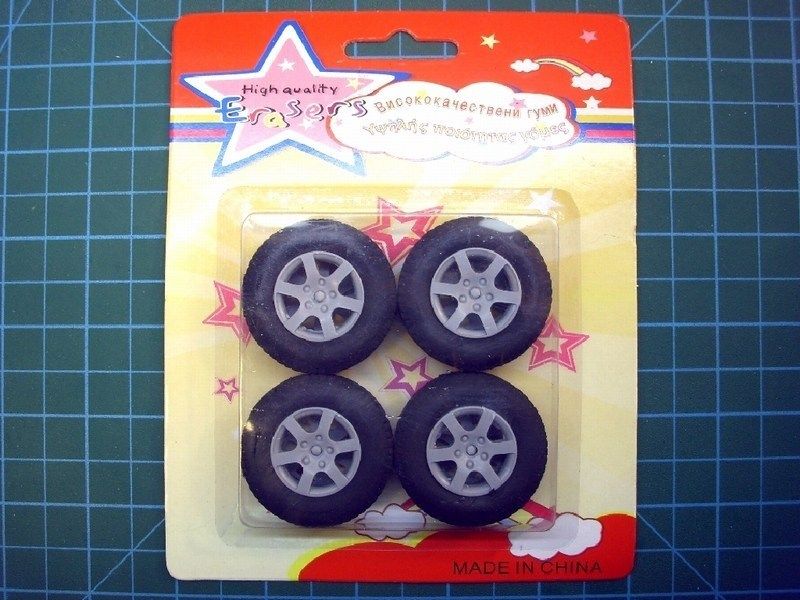
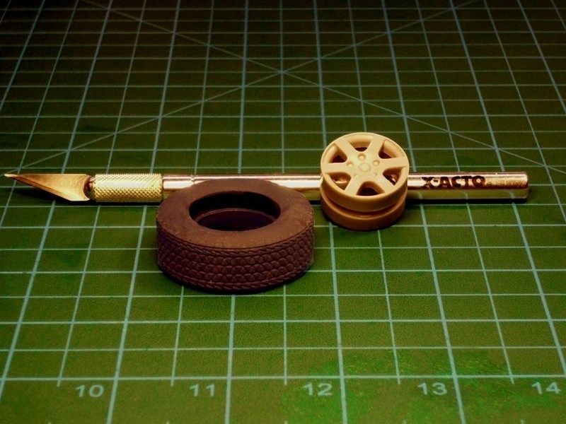
As people say, everything starts with a wish. And then, just like that, while shopping at the supermarket, I found the following item (actually a pencil eraser set for kids), for 0.5 € only. Sometimes the simplest idea can make the biggest difference and it looks like someone had the idea to produce & sell some pencil erasers that look like car wheels, waiting for me to find it, when I need it. Since I found this item which looks like a weathered wheel tire and seems to meets the criteria for 1/18 scale size, for a cheaper than dirt cost, I had no reason to 3D print the tire.
PS. Damn’d, I should wish for “World Peace” instead of “I need a 1/18 scale tire”.
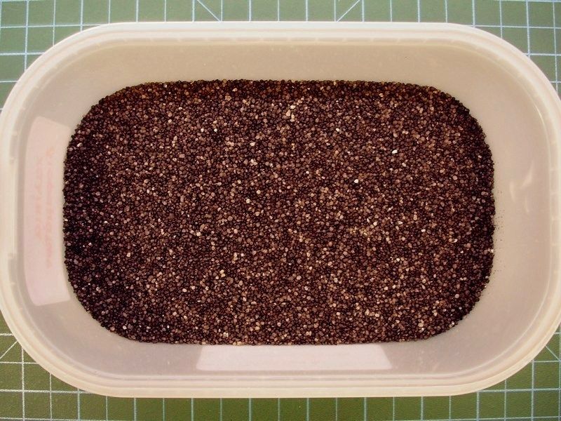
I removed the rim and filled the inside of the wheel with plaster to recreate as closely as I could the rough surface of cast cement & gravels. Because the plaster mixture was quite watery, I had plenty of time until become hard. So I also added some grains of volcanic sand into the plaster mix, hoping to recreate gravels. These volcanic sand grains (hand picked during summer vacations at the island of Santorini) seem to be ideal for the purpose and weight much less than normal beach sand.
As soon as the plaster cast got harden, the anchor was sprayed over with Humbrol light grey acrylic primer to get prepared for the FS 37038 "Matt Black" available by Life Color as LC02 acrylic. Later, the gravels were also painted with light gray & sand shades.
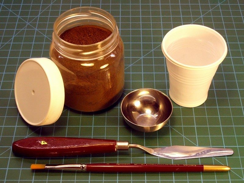
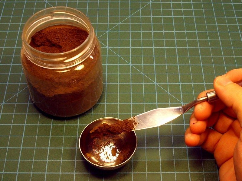
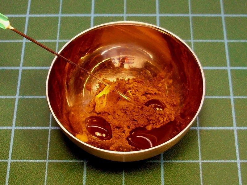
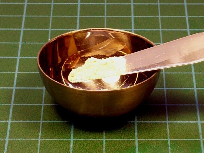
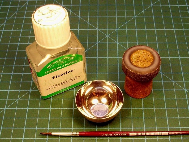
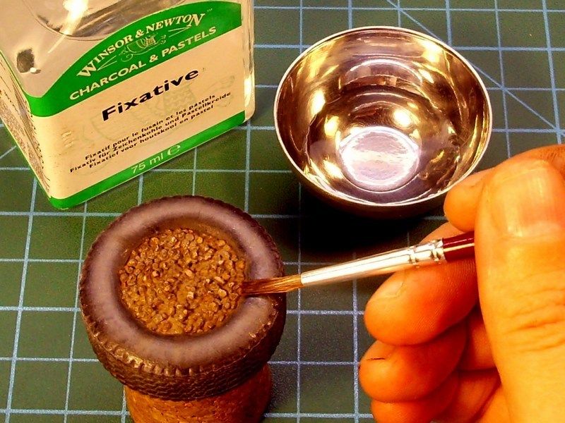
The paint allowed to dry for a couple of hours before starting the dusting process. The next two steps involve the use of pigments, which would give visual interest on the old & weathered tire. To get best results, I used "Raw Umber" pigment, a small metal cup, a flat brush and a bit of water. I add some grams of pigment powder and few drops of water into the cup to make the right mixture. It is important to add a tiny amount of water in order to make the mixture look like mud - not like soup. For this reason, I use a syringe to add just few drops on the pigment powder and I stir using the brush. The pigment applied with paintbrush with pressure, over the whole surface.
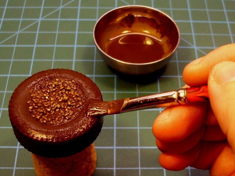
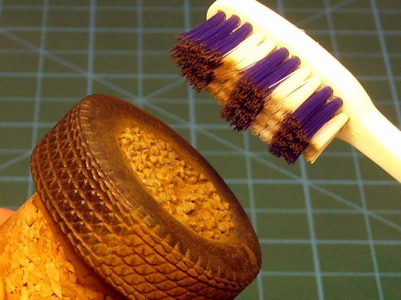
When the pigment wash dried, I rubbed off the high spots with a hard toothbrush and removed the dust excess. The high spots were cleaned to the basic finish and the low spots were left dusty. As soon as it looked OK to me after brushing & removing "Raw Umber" pigment dust, I continue to second step and add some grams of White pigment powder in the metal cup. Using a flat brush, I tried a pigment powder drybrushing, on the areas that supposed to be more enlighted.
Afterwards, the surface was soaked with fixative by Winsor & Newton, to fix the previously applied pigments, moving in a motion outwards the center of the wheel. As a final touch, I tried some drybrushing on gravels, using light gray & sand acrylic paint.
-
The tabs that connect the PSP plates together; They look like hooks. Bend a few of them to give it a more used and abused look.
Hmmm, yeah I can now understand what you mean. Looking closer on a picture of a fence made of PSP plates, I noticed that bended hooks. Your idea is very good and it would really add another degree of realism to the PSP plates!. But... the problem is that these 1/18 scale plates, are not photoetched or made of white metal to bend them easily. They are made of plastic - a very flexible one (did you check the picture uploaded before?). Even if I try to bend some, to look more damaged, after few seconds, the hooks will return back in normal position. To be honest, if I only knew that before printing these plates, I could make some of the hooks look warped and bended. Now, I think there is no point to build new 3D file with damaged hooks and replay all the painting and weathering process from the start - that would be a useless torture for me.
-
Are you going to mangle any of the interlocking tabs? It would add yet another degree of realism to your PSP plates.
More? OK, let me hear what do you suggest
-
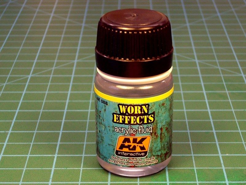
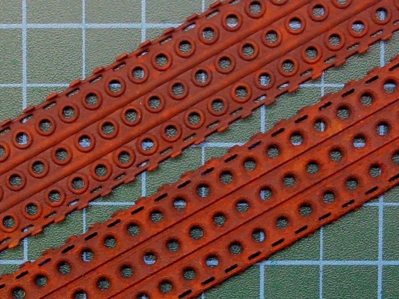
Once the "Vandyke Brown" filter was fully dry, the next step was to apply a paint layer, to create the chipping effect. This could be done using the hairspray technique and in this case I did use the AK Interactive’s "Worn Effects" which has been developed for exactly this type of effect and would guarantee consistent results.
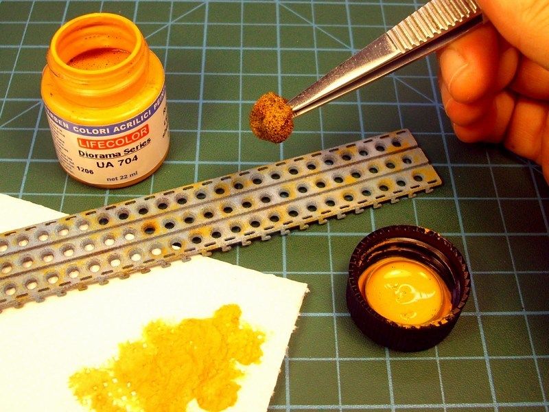
With the "Worn Effects" coat dry, some Life Color UA512 "Light Blue RLM 78" acrylic airbrushed on, in a random cloud pattern. Once dried, more sponge chipping added, using the Life Color UA704 "Rust Light Shadow 2" acrylic.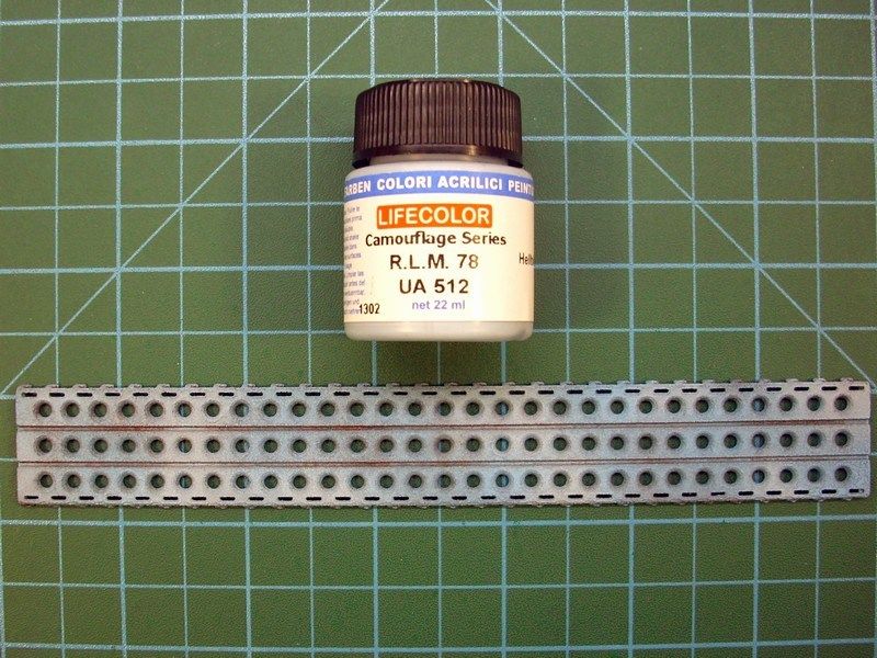
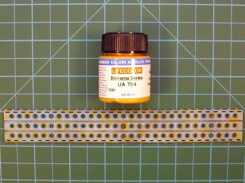
The paint allowed to dry for about an hour before starting the chipping process. To chip the paint, I simply wet the PSP plate surface with warm tap water and let it soften the paint. Some old stiff bristled brushes & toothpicks were used to scrub and dab the plate’s surface, to create the chipping effects on the light greyblue areas.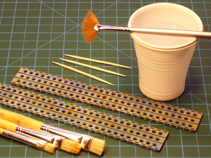
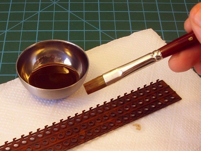
Fresh rust marks also added in some selected points, with some of the Life Color UA704 "Rust Light Shadow 2" acrylic. Using a fine tipped brush, the "Light Rust Brown" & "Dark Rust" oil paints by 502 Abteilung & AK Interactive series painted in vertical lines from various chips and scratched added earlier. Once the oil paints had been allowed to dry for a short while, a brush dampered in White Spirit used to blend and soften these streaks for a more subtle effect and obtain visible signs of wear & oxidation.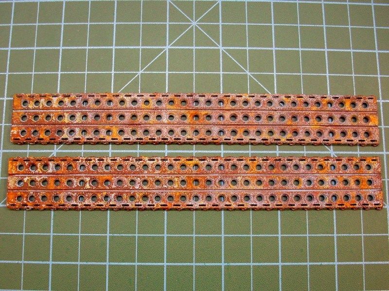
Hmmm, is the camera too far to see details? OK, let’s zoom and get a closer look on oxidation effects & light greyblue paint chipping. To be honest, I'm starting to believe, that my attempt to turn a pigs ear to silk purse, is quite possible to succeed.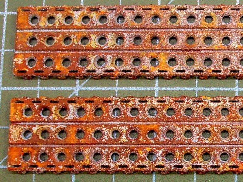
-
2
-
-
Awesome! Did you print the PSP yourself? Or did you have someone else do it?
Small parts, are printed with home printer. On the other hand, for the wings printing (approx 70 cm from one windtip to the other) I had to forward the file to industrial printer.
-
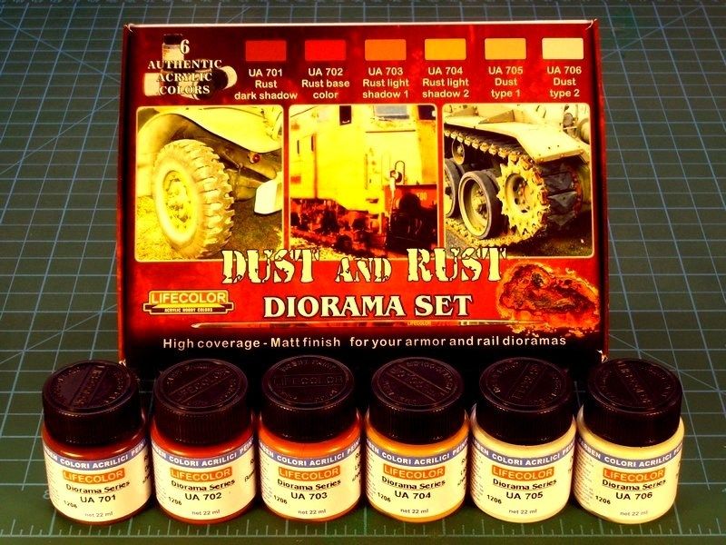
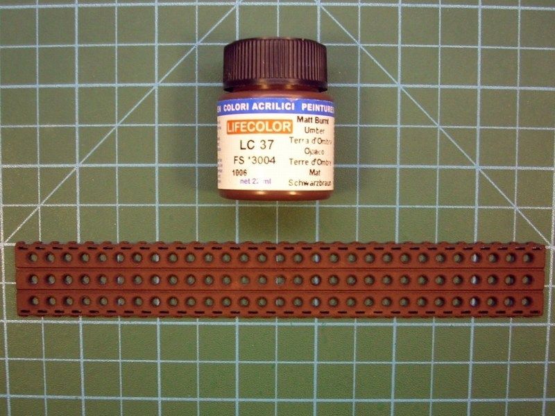
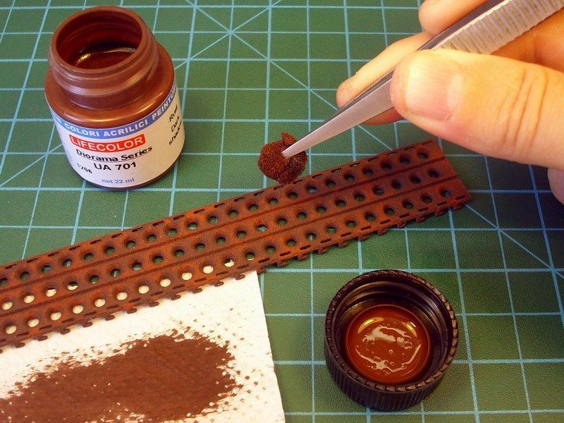
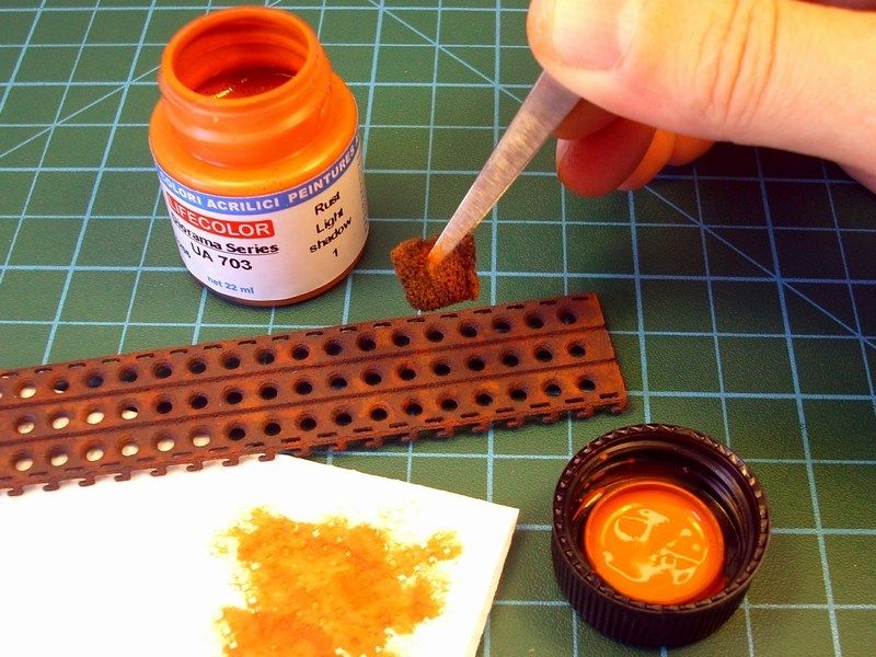
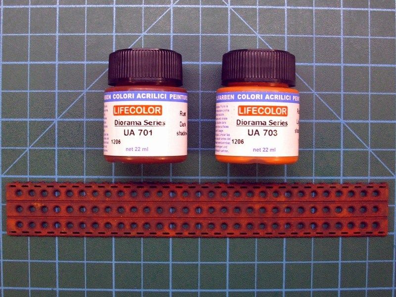
Replicating rusty metal, sounds like the Quest for the Holy Grail for an average scale modeler like me. Of course, the books, the videos and the tutorial seminars provided by famous scale model masters, helps a lot to understand some basic principles. Furthermore, the available tools & materials today, makes our life much easier. However, whenever I attempt to recreate rusty metal, I feel like a rookie and I'm never entirely satisfied with the result. In my attempt to recreate rusty PSP plates, I did use the Life Color's "Dust & Rust diorama" 6-pack set, of 22 ml bottles.
- Life Color UA701 "Rust Dark Shadow" acrylic,
- Life Color UA702 "Rust Base Color" acrylic,
- Life Color UA703 "Rust Light Shadow 1" acrylic,
- Life Color UA704 "Rust Light Shadow 2" acrylic,
- Life Color UA705 "Dust Type 1" acrylic and
- Life Color UA706 "Dust Type 2" acrylic.
The first thing I had to do, was apply a base colour on the PSP plates. For a base colour of steel plate I did use the FS3004 "Matt Burnt Umber" available by Life Color as LC37 acrylic.
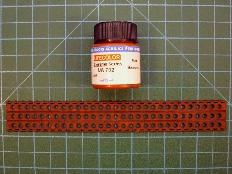
Later, using a fine brush and the Life Color UA702 "Rust Base Color" acrylic, from the previously mentioned "Dust & Rust diorama" 6-pack set, I covered the area with irregular spots. What I noticed while using the Life Color's rust shades, is that although the paints appear to be bright in color, they dry darker and are a perfect match to the real thing.
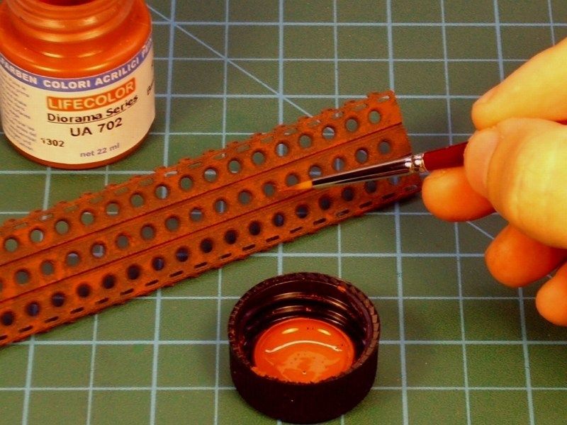
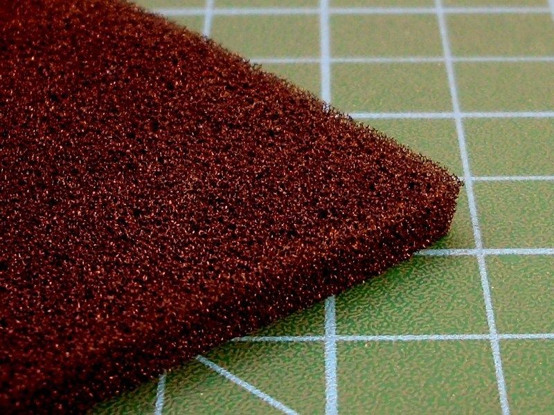
The next two steps involve the use of the sponge technique to add the small chips, which will give visual interest to the base colour. To get best results, I did use a fine textured sponge like those used for packing of electrical items.
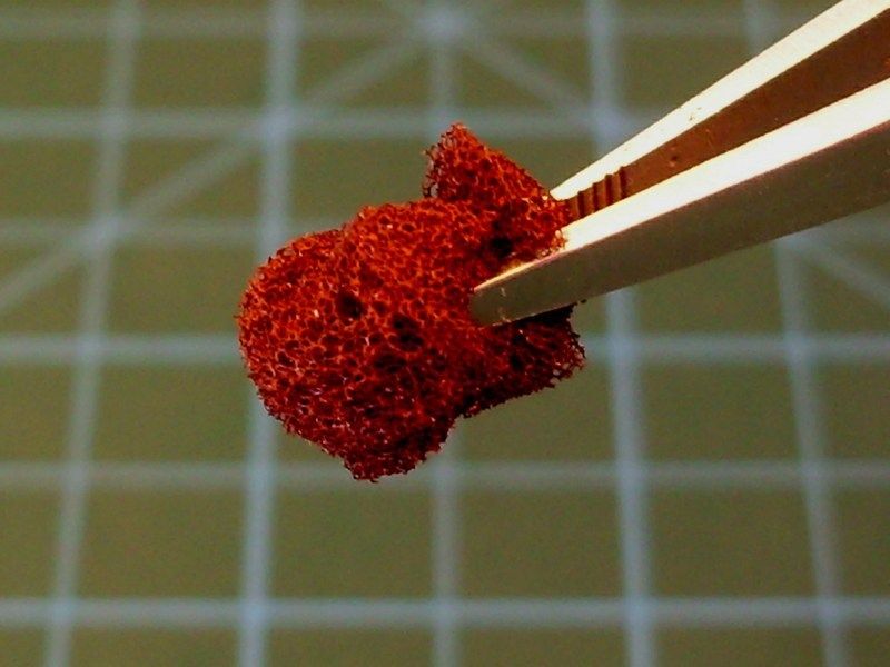
For the first colour, I chose the Life Color UA701 "Rust Dark Shadow" acrylic. For the second colour, I chose a rust tone that is brighter and lighter than the previous base colours. First dipped the sponge in the Life Color UA703 "Rust Light Shadow 1" acrylic, then remove the excess on a paper towel - otherwise it would end up with large blobs of paint on surface instead of a chipping effect.
Following, a dense oil paint filter should be applied. In this case, I did use "Vandyke Brown" available by Winsor & Newton, thinned with White Spirit thinner to a consistency between a filter and a wash. This would help to unify the previous effects and tones.
-
1
-
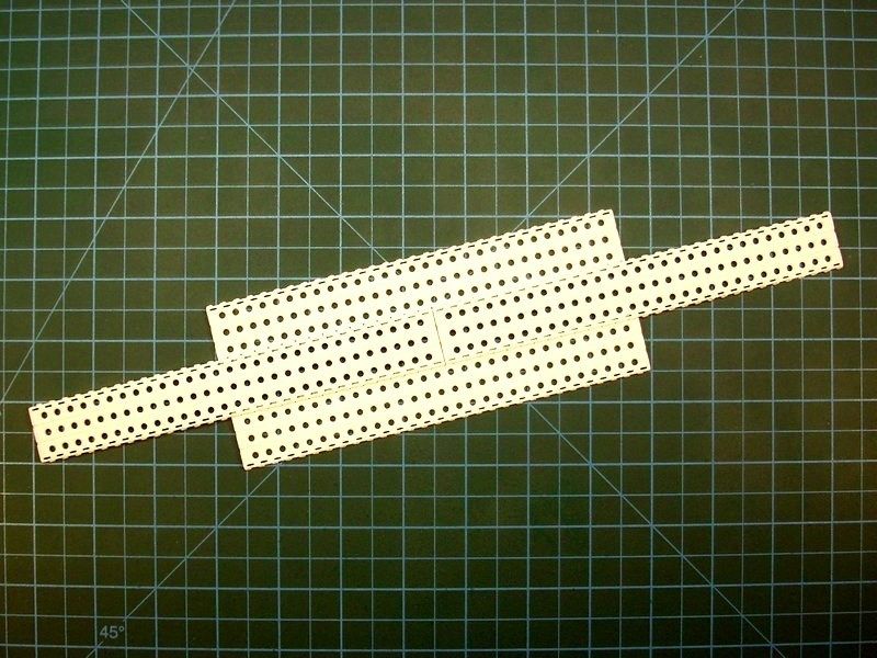
CHAPTER VIII - Terse abandonment
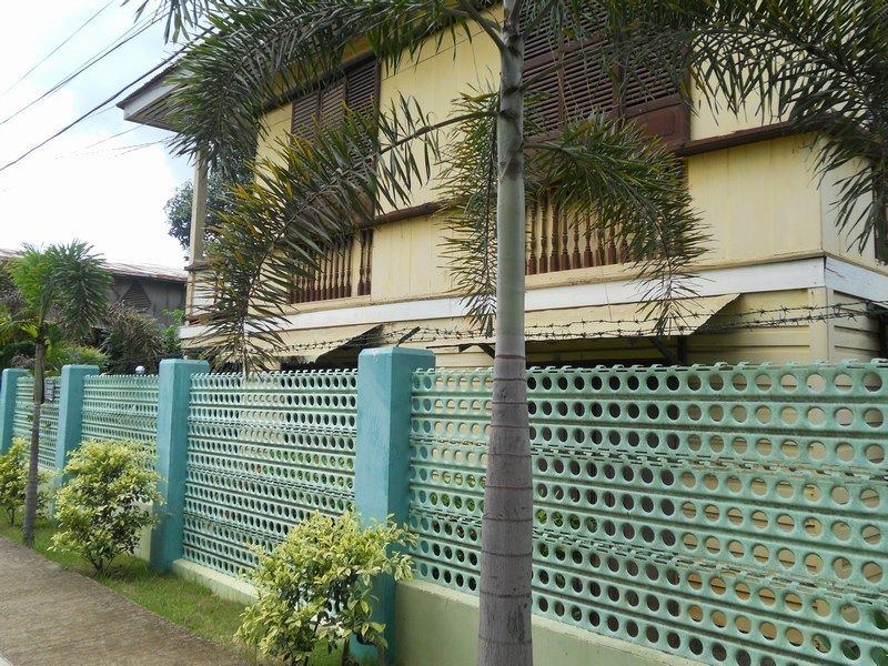
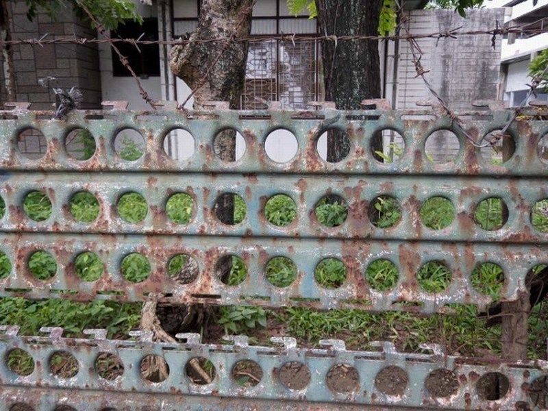
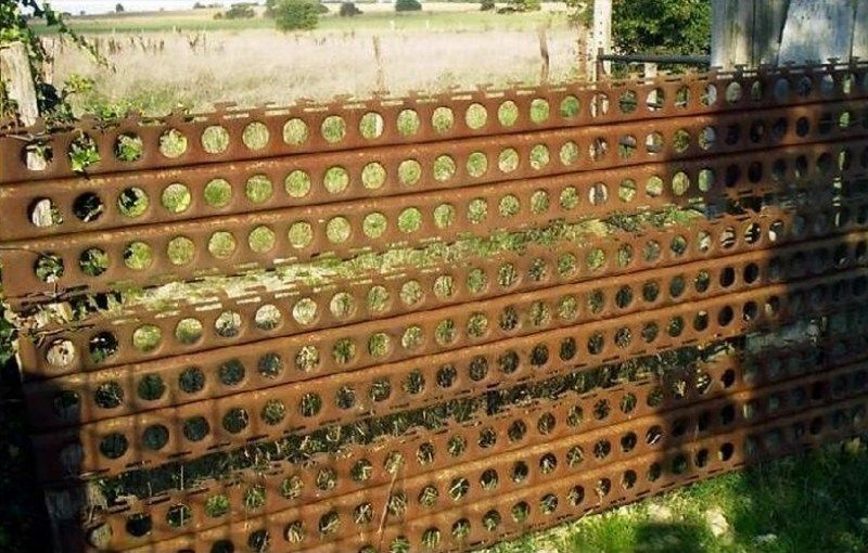
As previously wrote, my objective is to establish a scene of terse abandonment, without extreme features that could distract viewer’s attention, keeping the glider as the main protagonist of the story. The addition of a deflated windsock and a couple of Marsden matting / PSP - Pierced Steel Planking plates, seemed good idea to me. The PSP plates, were used during WWII to lay down airstrips. These mats were large perforated steel sheets each measuring 300x30 cm and weighing around 30 kg. They quickly interlink and with a bulldozer for levelling and enough manpower for the laying, an airstrip could be created overnight. The post WWII years, farmers and home owners used them to build garden fences, pig sties, chicken coops, benches, improvised bridges & ramps or as reinforcing panels in concrete buildings.
As earlier described in detail. the windsock was built by Milliput putty. On the other hand, the PSP plates construction, would follow the 3D printing way. It took only 15 minutes of CAD work on my laptop and voilà, we have a winner! A new 1/18 scale PSP plate virtual model, is ready to be forwarded to the 3D printer and become an actual object, within few minutes only. As previously described, the file can be scaled up or down to reach the desired dimensions, with few mouse clicks only and later be 3D printed under any scale. Yes, I could scratchbuild some PSP plates with my own hands, using metal foil or by vaccumforming styrene sheet, but I would surely spend much more time. The easier, the better! Actually, I'm not really sure if the handmade result would be so accurate in scale or if I could possibly build it within few minutes only.
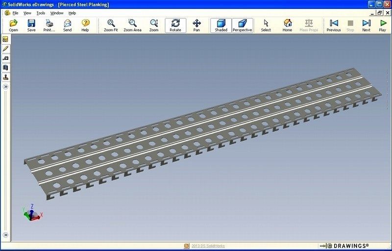
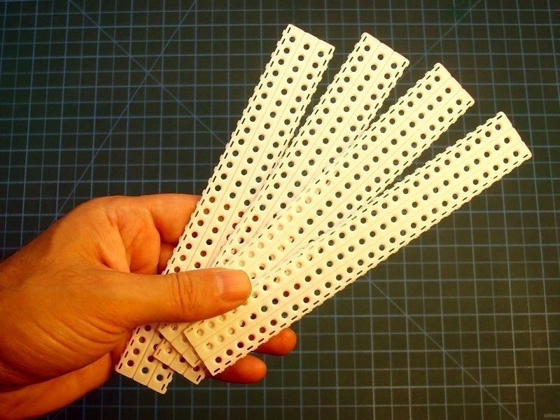
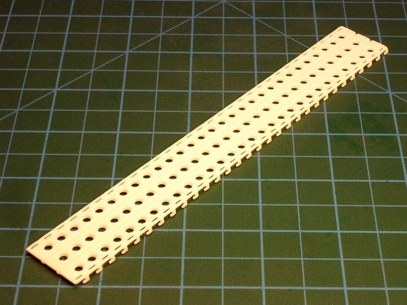
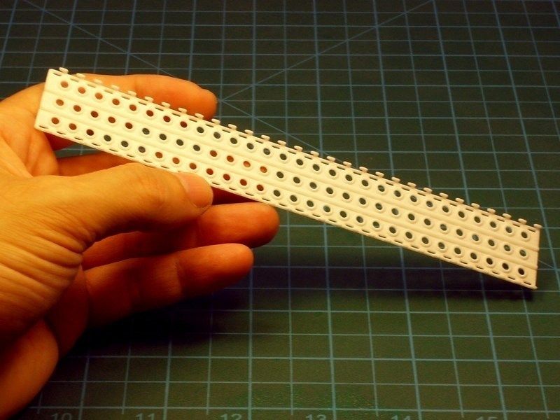
The material used for the 3D printing, is a white plastic (not rubber) that can be handled just like any other styrene part, but its surprisingly durable and incredibly flexible. Additionally, the side hooks on 3D printed PSP plates, can be used to interlink the parts - just like the real one.
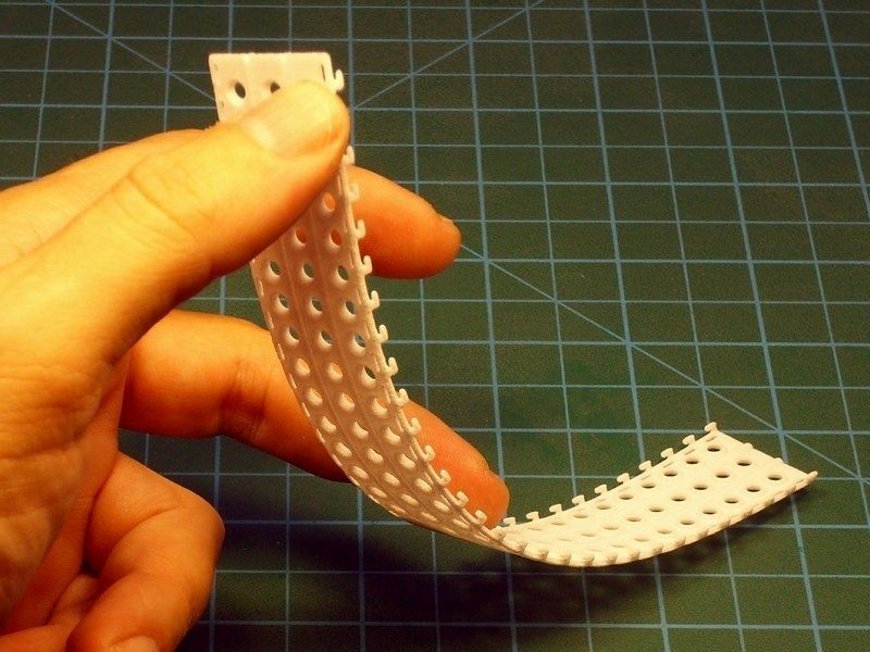
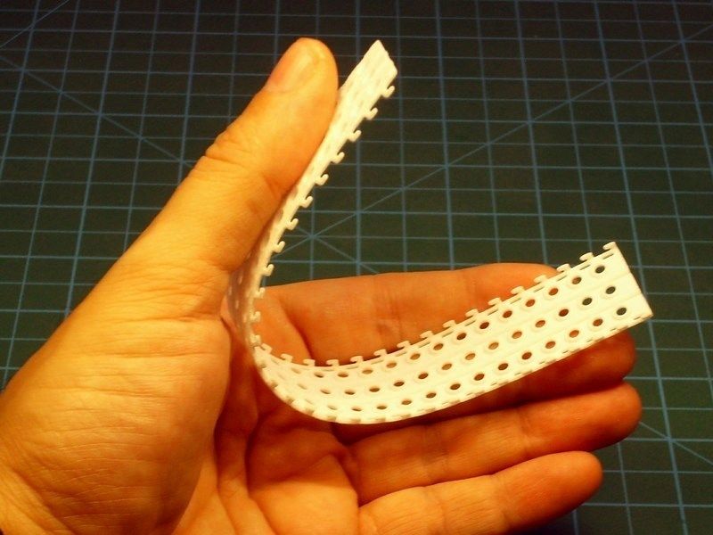
The 3D printed PSP plates washed with liquid soap and warm water and sprayed over with Humbrol acrylic primer to spot any mistakes and prepare for painting. At first, I was planning to leave the PSP plates on ground and let the grass grow through the perforated sheet. Considering the dense green grass covering, I thought that it would be better idea to place them as a part of a rusty fence. The fact is that actual PSP plates do rust when left abandoned for long period of time and available photographs proove it. Since I had in mind to build these plates to look abandoned, I had no reason to avoid an overall rusty colour tones & weathered effects painting.
-
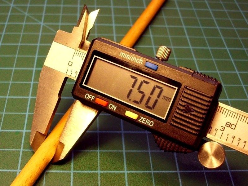
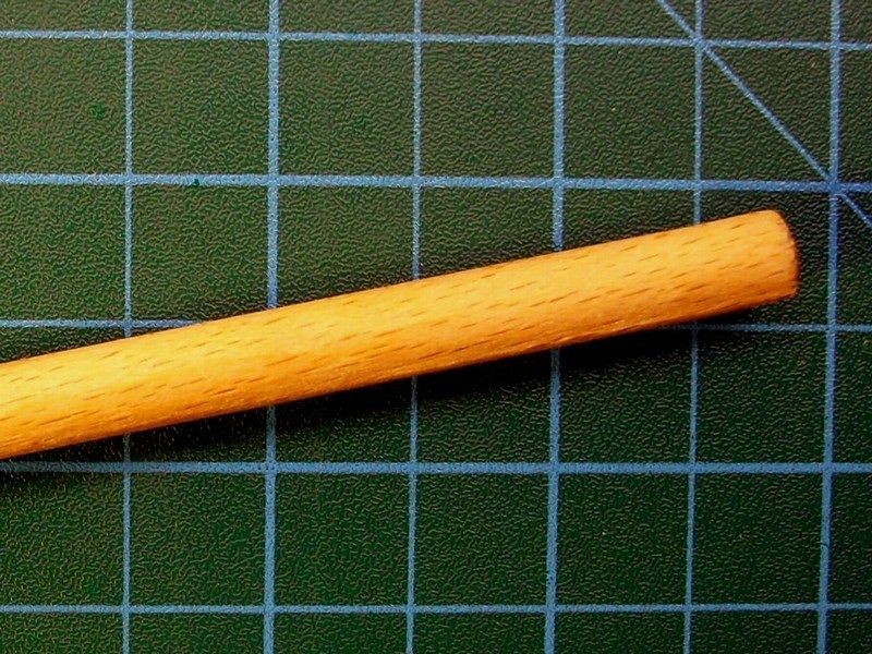
CHAPTER VII - Pole dancing
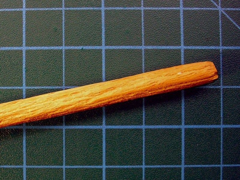
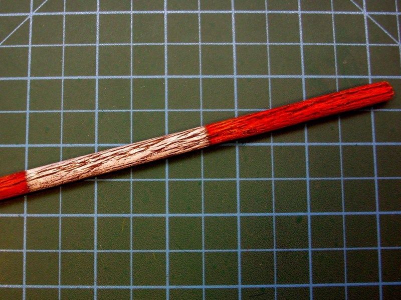
The windsock presented earlier, needed a pole to be placed on. I thought it would be a good idea to build the windsock pole to look like it's made of weathered wood, instead of some metal structure. To achieve the wanted effect, I used a 7.5 mm diameter wooden rod, which I managed to scribe with a wire brush, to obtain wood traces and look more realistic. Later, the radomly scribed wooden rod, repeatedly washed with diluted mixture of 5% "Raw Umber" oil colour and 95% White Spirit thinner, until get the desired tonality. Once the result was OK for me, I left it alone to dry for two days and then I tried some drybrushing with "Yellow Ochre" oil colour, to slightly tone up over selected areas that IMHO should look more enlightened. Finally, I sprayed over with hairspray - the cheapest I found at my local supermarket - to prepare the surface for paintscratching.
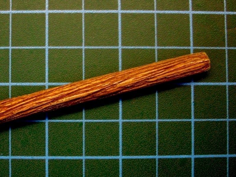
To paint the pole, I used the FS37925 "Matt White" and the FS31302 "Matt Red", available by Life Color as LC01 and LC06 acrylics, applied with a soft brush. I would say the pole is drybrushed more, than painted actually.
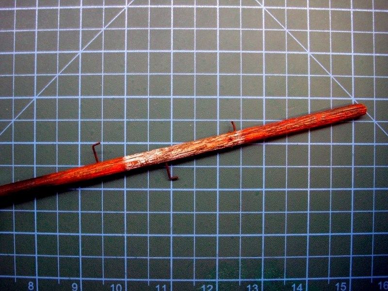
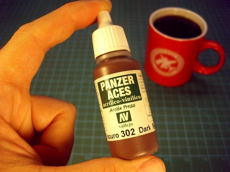
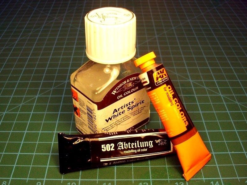
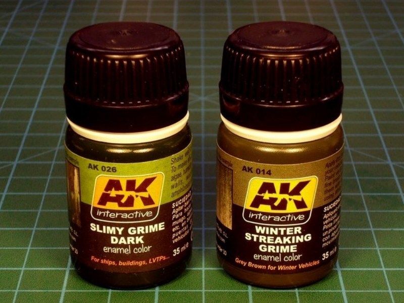
I left the red & white acrylic paint on windsock pole to dry for few hours and then I tried some paint scratching with an old toothbrush, previously moistened with water. The hairspray layer onto which the red & while acrylics had been dyed, began to dissolve and to drift along the overlying paintjob, giving the impression of weathering on wood pole. Additional details such as bolts were also placed and painted with the "Dark Rust", available by Vallejo as 302 acrylic. Rust stains and slimy grime streaking, later apllied on selected areas, using the "Light Rust Brown" & "Dark Rust" oil paints by 502 Abteilung & AK Interactive series and the "Slimy Grime Dark" & "Winter Streaking Grime", available by AK Interactive as AK026 and AK014 filters.
-
1
-
-
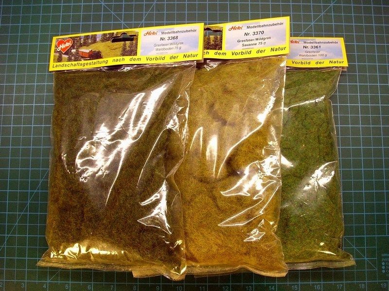
As previously stated, the scene supposed to takes place in Spring. Next job is to plant an additional static grass layer over the grass carpet. To do so, I used different colours of Heki static grass found at my local hobby shop. Heki, also specializes mostly in train dioramas. Someone might ask, why I had to apply the grass carpet first and then spread additional layer of static grass, rather than just settle for 2nd option only. The reason that I followed this tactic, is to ensure that the density of the grass would be satisfactory, such that the soil underneath, would not be visible. It could be arguable, that this tactic might be double work for nothing. Well, I only hope that the final result will worth the experimentation & risk taken.
So, I pick a small quantity of water based white glue, placed it into a small metal container, add just few drops of water with a syringe to make the right mixture and finally I applied on the desired areas to be filled with additional static grass & plants, using a wet brush. Because the mixture is enriched with water based glue, it is easy to correct possible mistakes.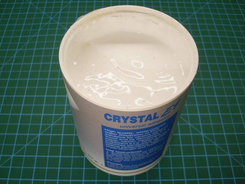
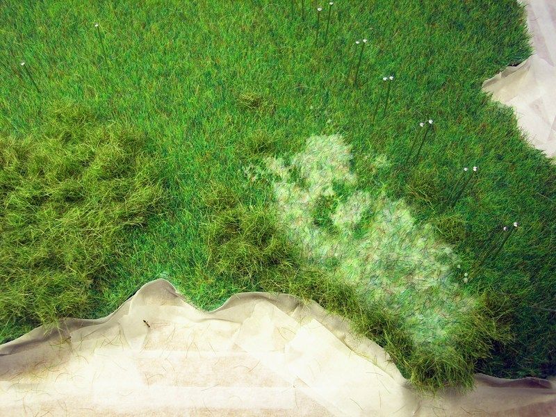
No, this is not the final form of grass - be patient for next WIP updates. For the moment, I am watering the base twice a day, hoping the grass to grow soon.-
1
-
-
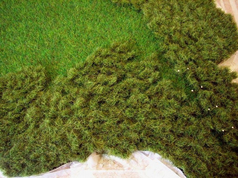
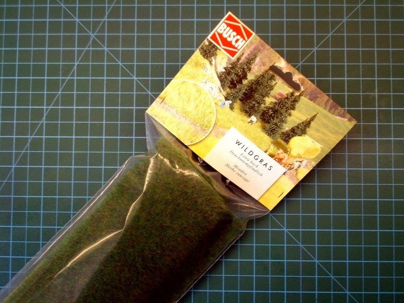
Unlike the regular practice followed in my previous projects, in which I glued static grass & plants directly on ground untill filling the whole area, I decided to change for an easier and more appropriate method, taking into account the increased surface to be covered. To do so, I bought a 50x40 cm size green grass carpet, made by Busch which specializes mostly in train dioramas. The green grass carpet will be glued on the 10 mm thick sheet of balsa wood and will become the main substrate of a dense grass covered ground. Later, I plan to add more static grass & plants, to avoid the monotonous flat football field alike green pattern and make it look closer to reality.
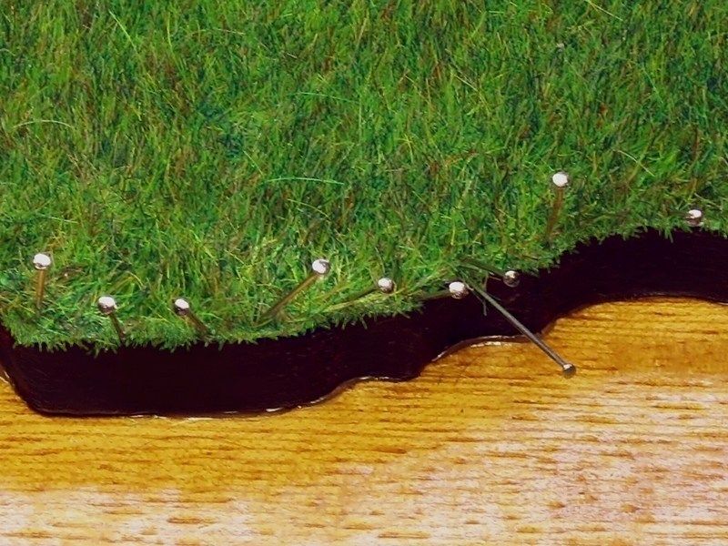
Using scissors, I cut around the Busch's grass carpet, according to contour of the 10 mm thick balsa wood sheet. The grass carpet was secured in place with steel pins and glued onto balsa using water based white glue for wood, which becomes transparent when it dries. Once the process complete and the glue dried, the steel pins which kept the grass carpet nailed on balsa sheet, were carefully removed.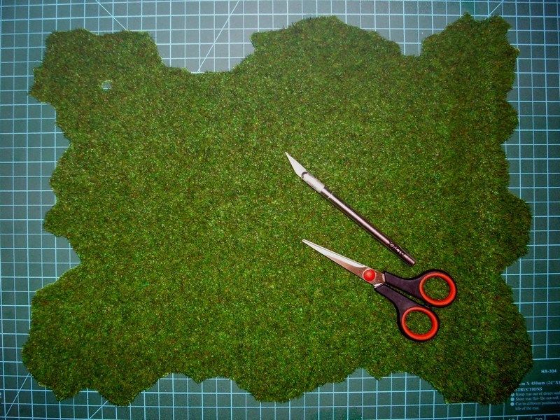

-
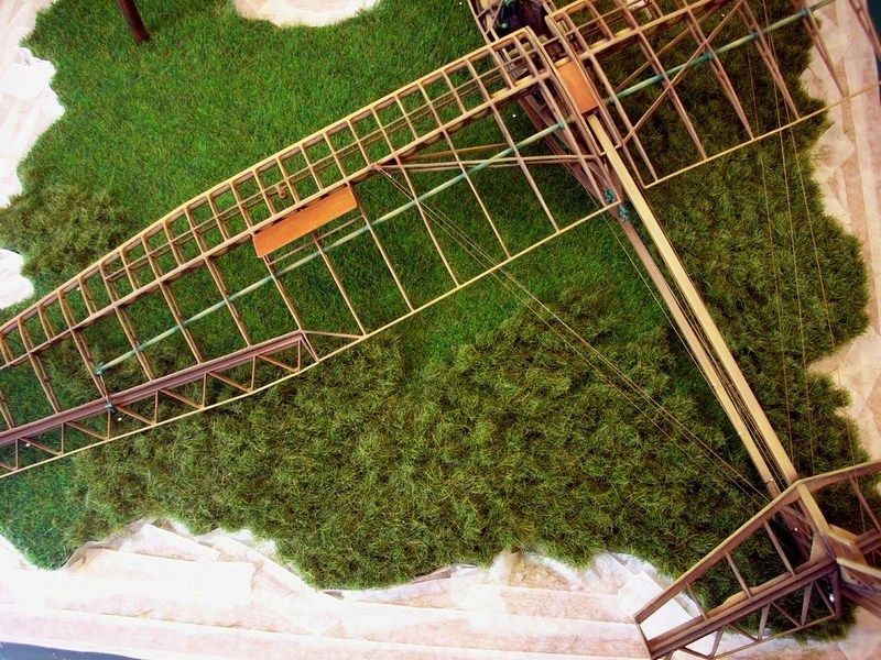
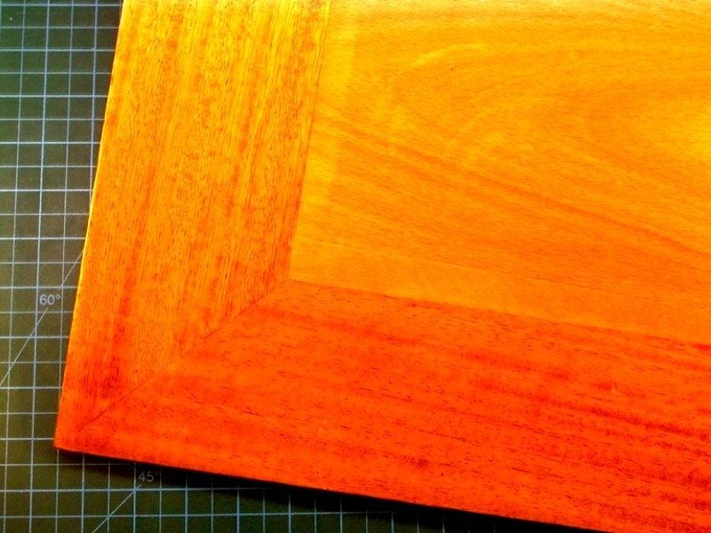
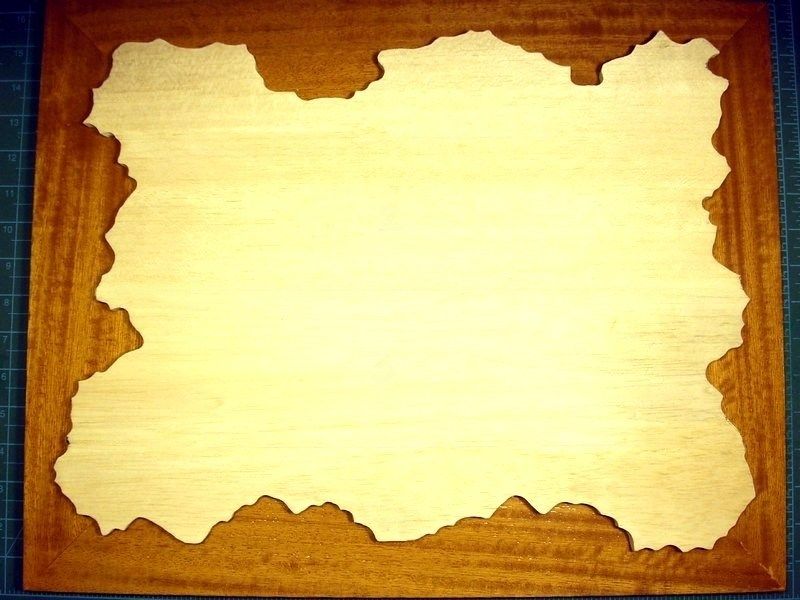
The whole grass field scene would require a 50x40 cm display base, considering that glider measures approx 70 cm wingspan in 1/18 scale. That could be a problem for my show case in home, which yes, it is big, but not big as an elephant. From the MDC - Model Display Cases store, I bought a 50x40 cm base, made of polished beechwood with MDF core.
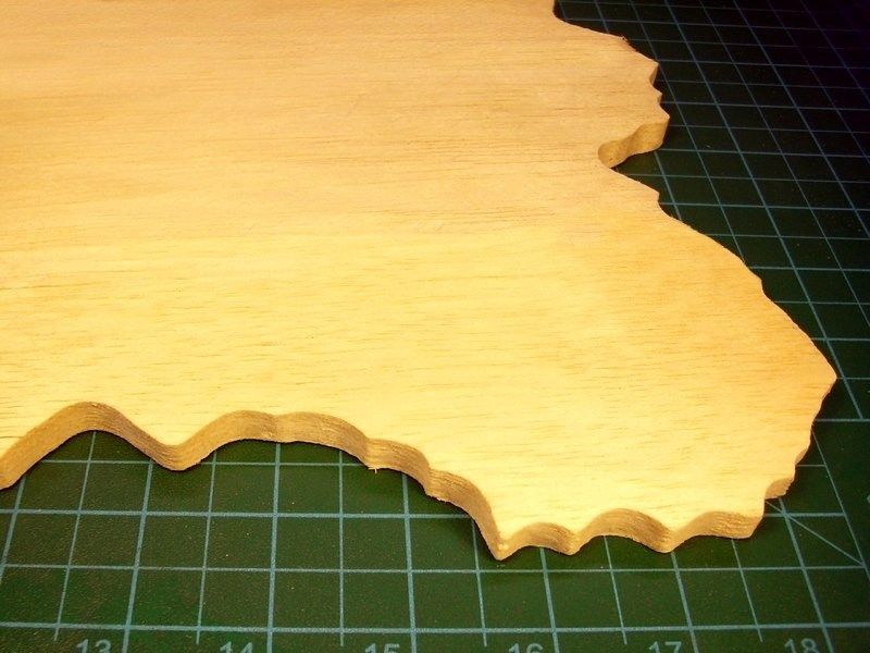
Those who have read my previously uploaded projects, might remember that I prefer using plaster powder to build the section that recreates the ground, especially if it is asphalt. However, the 50x40 cm dimensions of the scene dictate plaster quantity more (and therefore heavier) than usual and for this reason I chose to use another material, because my goal was to build a “grass field display base” instead of weightlifting equipment for champs. For this reason, I purchased a 50x40 cm size & 10 mm thick sheet of balsa wood from my local hobby shop, which I cut & shaped around with my cheaper than dirt Black & Decker 400 W / 3000 spm jigsaw bought for 20 € only. The basic idea, is to produce a thick & flat surface which protrudes approx 10 mm beyond the polished beechwood base, on which later green grass & extra stuff will be added where is needed.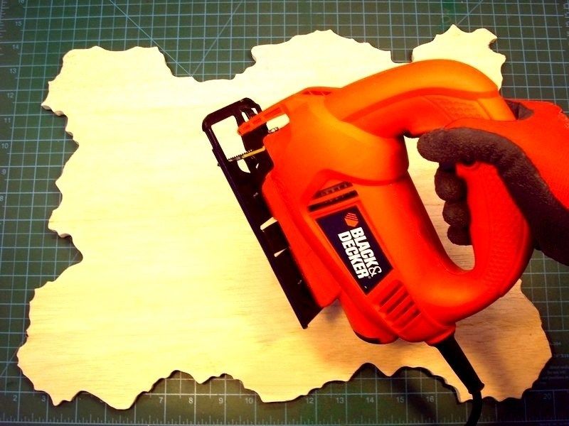
Remember that operating a freehand held jigsaw could be a bad idea if not pay attention on job. Sawdust may also cause problems when breath or shallow. A powerful vacuum system to suck away the dust should be used all time to keep the workbench area clean. Using a breathing mask & pair of protection glasses to prevent dust contact with lungs & eyes, is also an important matter that you should seriously take care of. My recommendation is to also wear working gloves - made of kevlar if possible.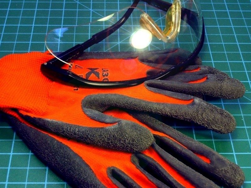
1/18 scale Wallis WA-116 Agile autogyro scratchbuild model
in LSM 1/35 and Larger Work In Progress
Posted
I found nice idea to place the Wallis WA-116 Agile autogyro model on a display base, simulating a maintenance & refueling area with short grass sprouted between concrete slabs. My goal is to recreate a scene of an airfield apron area where pre-flight activities were done. An apron is any area for parking and maintenance.
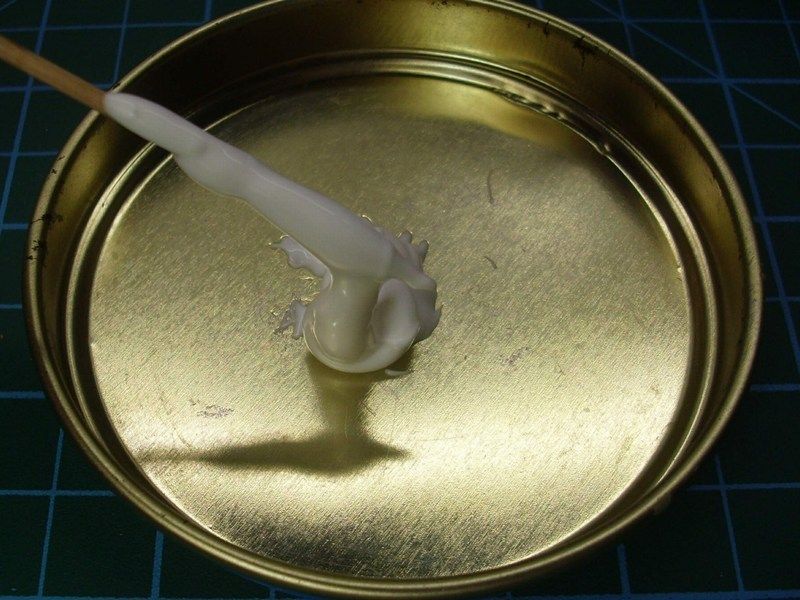
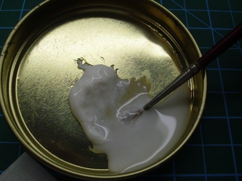
I add some grams of plaster powder and few drops of water into a soft rubber cup to make the right mixture. Materials like plaster, start as a dry powder that is mixed with water to form a paste which liberates heat and then hardens. Plaster remains quite soft for few hours after drying and this characteristic make it suitable for the job.
Keep in mind that:
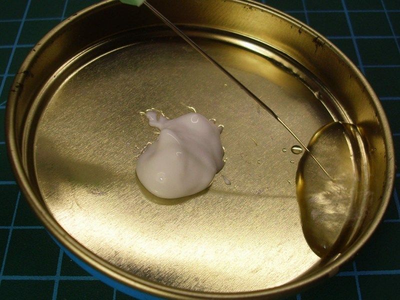
When the first layer of thinned plaster applied on a clean surface, a flat glass were pushed against the plaster to form a flat basic strong cast. The basic idea, is to produce a totally flat cast and later add some detail or apply extra stuff where is needed. I left it few hours to get harden in order to be sure that the cast wouldn't break when I would try to cut it into desired shape. Meanwhile, I took the soft rubber cup which I used to make the plaster mixture, squized it to break the last hardened plaster left inside, so it would be easier for me to clean it afterwards and prepare it for any future mix. That's the reason this soft rubber cup were used for.
As soon as the plaster cast got harden, cut into shape and the concrete plaques were lined with a scriber, I used my airbrush to paint it. As I usually like to do, three different acrylic paint layers were applied on the plaster surface. First, mat black colour covered the area and then a light grey applied with airbrush, spraying in almost zero degrees angle, to let the darker areas between the concrete plaques remain naturally dark. The corner was paint with lighter grey & earth tones and as soon as the acrylic colours dried, I tried some drybrushing on selected spots using sand tones.
As for the vegetation that grew between the concrete slabs, I used some Heki static grass found at my local hobby shop. Heki, specializes mostly in train dioramas.
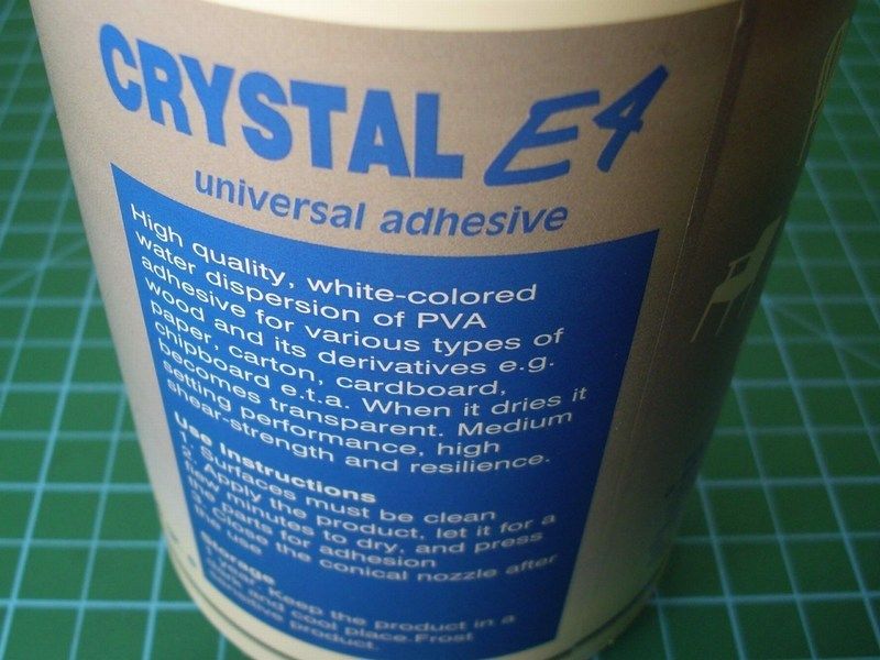
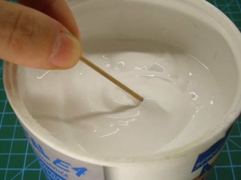
Water based white glue for wood, which becomes transparent when it dries, is just the right for the job. So, I opened a 500gr canister bought for €2 only, pick a small quantity, add just few drops of water with a syringe into a small metal container to make the right mixture and finally I applied on the desired areas to be filled with grass & plants, using a wet brush. Because the mixture is enriched with water based glue, it is easy to correct possible mistakes.
As soon as the result was OK, I sprayed over with Humbrol enamel mat coat, to seal the paint and grass, so far. I left it overnight and as soon as the enamel mat coat dried, I add very few light & dust effects with chalk dust and pigments. For those who may say that the vegetation sprouted between the concrete slabs looks excessive for an active apron, think again. I 've seen European capital international airports, with jungle-like grasss on apron ground area.
From my local store, I bought a 20x30 cm shiny laminated wooden picture frame. The empty space, filled with 5 mm thick sheet of balsa wood. The plaster made ground, paint already, carefully moved on laminated wooden base and secured in place with silicon glue.