

Nick_Karatzides
-
Posts
179 -
Joined
Content Type
Profiles
Forums
Events
Gallery
Posts posted by Nick_Karatzides
-
-
CHAPTER X - Epilogue
Final details were added. VHF radio with headphones in the cockpit, mobile phone, seat belt buckles, main rotor control bars, cables, etc. To break the monotony of red, a toolbox and a tow added into rear storage area. At last, transparent plastic card were placed to simulate the wind shield glasses and of course the canopy in the open position.
Close-ups of scratchbuild engine. Although initially I plan to represent a brand new bright and shiny engine I discovered that it would not fit the with a faded, dusty and weathered autogyro. That is why I preferred to add much wear, stains from oil and scorched medals at several points and some rust as example in the exhaust.


The controls in this two-seater model autogyro, as with any trainer aircraft, perform the same movements. Feel free to notice the rudder pedals and you will see that the front and the back seat, right rudder pedal is pressed to full FWD possition, bringing the left ruder pedal in full AFT possition . This has resulted in turning the nose wheel to the right and turning the rudder of the tail in such a way as to twist the autogyro to right as defined by the position of the rudder pedals. Also notice that the throttle lever of back seat is attached on a bar connecting to the front seat engine throttle so to move simultaneously. The engine's power transmission is made with a wire, launched by the front seat throttle lever and lead the assembly of the engine. Finally, the control sticks are fallen slightly forward, which of course means that the elevators are set in a similar position. Also notice that the position of controls (stick, rudder pedals and engine throttle) meet the relative position of the elevator and rudder fins, the nose wheel, etc. The front & rear seat rudder pedals perform exactly the same movements as linked to the same wire transmission. If you also check the rudder pedals position, you’ll notice right rudder pedals pressed front end, bringing the left rudder pedals full back. As an effect, the nose wheel turns to the right and rudder fin turns in a way to turn the autogyro to the right as defined by the position of the rudder pedals. In similar manner, both control sticks (which perform exactly the same movements as they are connected to the same bar drive) are positioned slightly forward. This has the effect of elevator fins rotation so as to oblige the autogyro in the descent, as defined by the position of the control sticks. In a similar position the main rotor head is placed as required. As it is known, the autogyros and the helicopters leans to the left or right, elevates nose up or descent nose down, by turning the main rotor blades disc and secondarily to aileron and elevator fins (if present) and turn to left or to right with the rudder fins (autogyros) or tail rotor (helicopters).
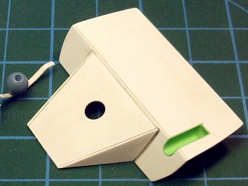
I’ve been asked about the available space where the rear passenger puts his feet on. From the pictures of the model have been published, and the art images found on the article’s first page, it appears that the rear seat is too close to the back of the front seat - and it is also clear from the blueprints of the real autogyro that it’s not my own assumption or a model building mistake. In real autogyro, rear passenger's feet are not squeezed behind the front passenger seat back, but they are placed left & right of the front seat! To make it more understandable, have a look in following pictures, showing a tandem cockpit seating positions as described:
- The green lines represent the front seat passenger and the position of his feet on the rudder pedals and
- The blue lines represent the rear seat passenger and the position of his feet on the rudder pedals.


-
Some update pictures after washing / weathering / color fading. Control cables are already installed. Still remain to be added:
- The canopy,
- Both propellers,
- The radio device & GPS,
- The engine control levers,
- The windshield and windscreen wiper,
and also paint some details such as engine cables etc.


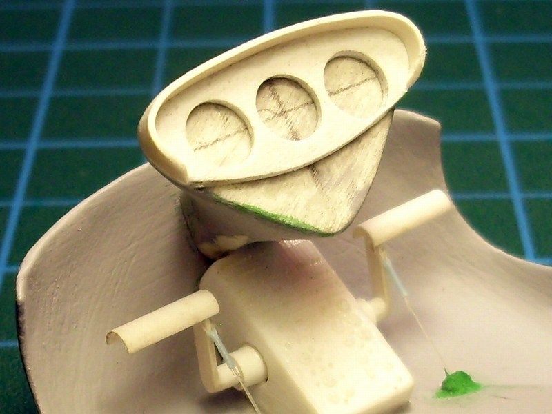
 Details on the rotor blades and the engine. The rotor blades are made of sterene sheet softened in boiling water to stretch 'n' turn in a way to look realistic. Soft sanding applied on the blade's leading edge to be shaped as it should be. The spinner cone was made of an old 1/48 scale fuel tank tip, found in sparebox.


 My little JT-9T princess is posing for the camera...


-
CHAPTER IX - Applying paint, wash & weather effects
Model parts were washed with liquid soap and warm water to disappear leaving oil traces, fingertips etc and then sprayed with light grey primer.


The first base color layer sprayed with no problem and then a second white color layer applied on specific spots to simulate enlightened areas. Then, using very diluted acrylic color Vallejo paint, 2-3 extra thin layers were sprayed throughout, until the result become realistic and simulate correctly the enlightened areas.


As soon as the previous layers of acrylic Vallejo paint and gloss coat varnish dried, I placed small slips of paper between the frame and the sheet of the fuselage, to protect the red colour that was already applied and dried. Next, I masked areas not to be painted using the adhesive Tamiya tape and sprayed with the interior green colour.


 After the interior colour dried, the slips of paper and adhesive masking tape removed and minor corrections were made in 1-2 spots with a fine brush. The result was sprayed with gloss varnish, to apply washing on certain points.


 The steps are slow, but I prefer steady progress rather than hastily. Unfortunately, the problems are not missed. Although I do not think myself as awkward, after the incident with the (voluntarily flying) autogyro model scaffolding under my sleeve and threw (launched to be precise) on its own initiative, brought about 4 or 5 spin turns and finally abnormal landed about 5 feet away and 3 feet lower, I begin to believe that this model has been seriously voodoo curses. Despite the delicate structure of the fuselage, the use of CA glue and maybe a mirracle, were the main reasons that the model escaped having suffered only a broken landing gear, scratchbuilt again.
After the scale model was masked & sprayed with primary colors as described above, the same methodology followed for the canopy, scratchbuilt by transparent plastic on a vacuum former. After the acrylic paint and mat enamel coat dried, I removed the masking tape and I saw the following:

The masking tape that I had used, had left noticeable marks on the transparent part of the canopy - something that had never done before! Being sure now that this scale model is indeed cursed, I dropped by the local grocery store around the corner from where I returned with few garlic cloves. Not having a similar experience before and fearing that if I try to clean the masking tape glue marks using White Spirit will make the things worse with a huge dull hood, I tried to rub the clear plastic part with alcohol which although more friendly to transparent plastics, had to pass crash test first. Dipping a cotton swab in alcohol and water solution and vigorously rubbing the hood, the masking tape glue marks, finally removed as if it was gum.


With my heart beating on normal levels again and using airbrush, light tones of basic colours and shades of sand sprayed at low pressure to represent the weathering and dusting on LG and the lower part of airframe. After a satisfactory weathering result, the scale model was sprayed with mat enamel coat. I left it 24 hours to dry and the individual parts of the scale model were test assembled (no glue), so that the autogyro model start to look like a united construction and please the eye.


Having now left the last part of the assembly of the individual already dyed parts of the model, such as the rotor blades, the cockpit flight & engine controls, the cables, the seat belts and other necessary details, I begin to hope that perhaps this model might be ready very soon. -
CHAPTER VIII - Live After Death
When I started building the model, I did not expect to present the CHAPTER VIII under this title. Bus as all the sad & bad situations in life, it was unexpected and accompanied by great frustration because suddenly I saw months effort to dissolve in only few minutes. The old colours (or bad white spirit solvent) that I used, have led to drying crack. Unfortunately, I ignored all the warning signs such as thick grains left by the white colour in which I primed the scale model before the final painting. Having as target to make this model alive again, just like Iron Maiden Eddie’s Live After Death, I decided to try a full reset – after all, I had nothing to lose! The scale model was already FUBAR.

The following photos show the unsuccessful paint process. The problems appeared marked inside the red circles. Unfortunately, I have no photos of the model while looked completely written-off, because at that time I was not in a mood to take pictures!


 ModelStrip, was the first thing came up as the most conventional solution to try paint removing. Following the instructions on the box, a generous stuff applied on the model, wrap it with airtight plastic bag to prevent drying and wait about 15 hours to let the chemical work. Opening the bag next day and checking the results, the colour (or rather the colour layers) were soft and could be removed by rubbing vigorously with an old toothbrush. Unfortunately, using the brush on some very delicate spots (even with careful use), had as result to break / or ruin a couple of plastic pieces. Moreover, the paint could not be removed through narrow points and difficult locations.
At this point and while I’ve already used all the ModelStrip material without being satisfied with the outcome, I decide to change tactics to something more unconventional, such as oven cleaner.
Following the product’s directions as always, I sprayed the model with the material, wrap it with airtight plastic bag to prevent drying and wait about 15 hours to let the chemical work. Testing results next day, the oven cleaner failed no more than ModelStrip. I noticed that the colour could be removed but only when pressure and persistent rubbing with brush and that was prohibitive for some parts of the model. Not having another solution, I approached the most unconventional method and visit a science specialist - my local grocery store!- - Hey man! I need something really strong to clean up kitchen’s oven?
- Really strong? Use this!


- - Are you sure that this will work? Are you sure that this is safe to use?
- Trust me. It’s gonna clean up the kitchen’s oven like a nuclear bomb!
- How much?
- 3.50 € . Take it or leave it.
Thinking about a possible failure, I filled a plastic bowl with the milky liquid contained in the bottle and threw all the model pieces inside. As long as the autogyro model was already FUBAR, I had nothing to loose to try. I sealed the bowl with a cover and leave the sodium hydroxide to act for 20-30 minutes while the instructions sets out to wipe the sodium hydroxide chemical liquid after 10 minutes. Opening the plastic bowl’s cover, a nice surprise followed...


 The truth is I was delighted! Styrene pieces simply and magically totally striped off the enamel colour layers! Absolutely success, without even apply brush cleaning! Amazing product - incredible grocer! Just because I couldn’t believe it and I wanted to make sure that the colour striped off because of the sodium hydroxide chemical (and not the previous used ModelStrip product or the kitchen oven cleaner), I decide to experiment. I threw in a bowl, already filled with the chemical, a 1/18 scale female figure that I was about to convert for a future project. The specific 1/18 scale female figure, is made by Fast Women brand and can be found by clicking HERE). The results after just 15 minutes in the sodium hydroxide chemical - Perfect! The following pictures, show the "before" and the "after".


Keep in mind that the sodium hydroxide is (and thus should be considered) a strong caustic base. This means that:- Throughout the impregnation of the model parts into sodium hydroxide, you should take all the necessary protective measures (like mentioned in the warnings on the bottle’s label) and is certainly to use disposable surgical gloves made by latex and breathing mask with appropriate filters to protect against possible fumes.
- The colour stripped plastic parts must be rinsed with soft acid to neutralize the caustic base and produce salt and water. Dunking the colour striped parts in plastic container filled with cooking vinegar and then rinsing with plenty of lukewarm water, plastic is now safe to handle with bare hands.
Under the above "adventure" circumstances and considering that all these years dealing with the scale modeling I've tried many color striping methods (including ModelStrip, kitchen oven cleaners, blue alcohol, brake fluid, nitro laquer disolvent, etc), I think that sodium hydroxide NaOH is the best method so far, for the following reasons:
- Kitchen oven cleaners in spray canisters, can do the job, but they cost 3 - 4 € for a 300ml product in which also includes the propellant gas. On the other hand, the NaOH in liquid form is a pure substance, much less price, taking for 1lt bottle, which equals 3.3+ times more product! Using the liquid form NaOH (which you can fill a plastic bowl), you can sink several plastic pieces, same time!
- The brake fluid may be effective and remove paint, but it is not plastic friendly plastic and is likely to convert the scale model into a blob of molten plastic. It is clearly more expensive and as far it is highly toxic, flammable and hardly to manege, I will not recommended it for scale modeling use.
- Nitric acid laquer disolvent, could be a nice solution for metal figures paint striping, but it is not the best for the plastic. Just like the brake fluid, it does melt and damage plastic parts.
- - Hey man! I need something really strong to clean up kitchen’s oven?
-
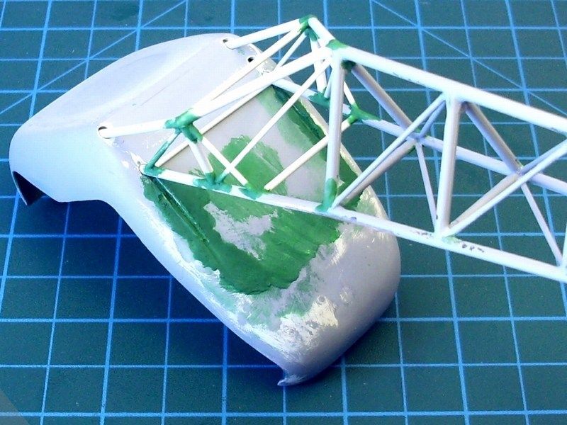
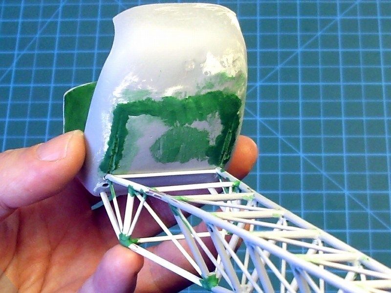
CHAPTER VII - Canopy construction
The Jukka Tervamäki Engineering JT-9T autogyro canopy is made by bented and cold-formed 3mm polycarbonate sheet. The backwards sliding canopy of the single seat JT-9 version, offers the possibility to taxi and fly slowly with the canopy open, a benefit in a hot climate. The trainer / tandem seating JT-9T, has a side opening one piece canopy. Of course, canopy modifications can be done, according the autogyro owner's personal needs or desires.


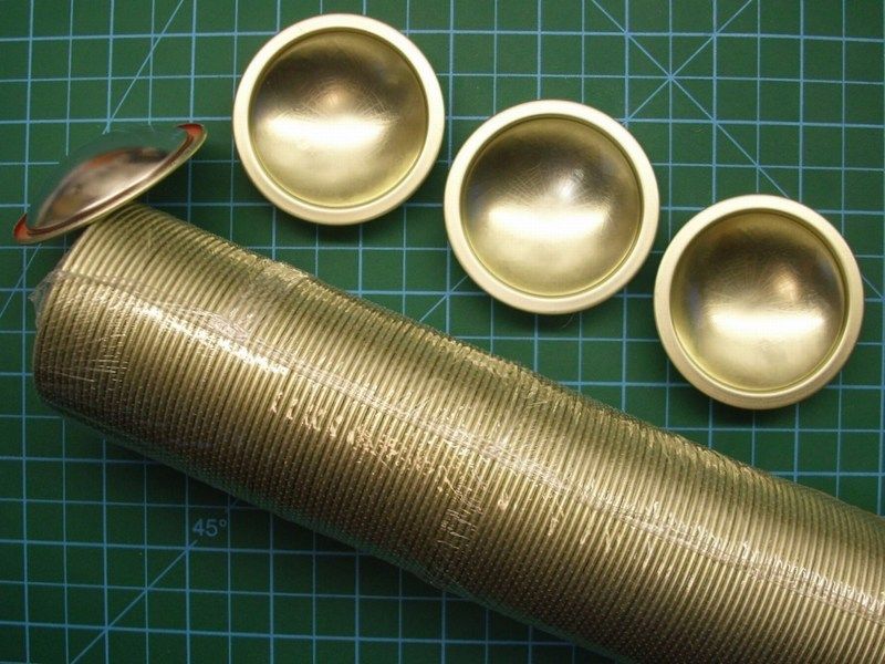
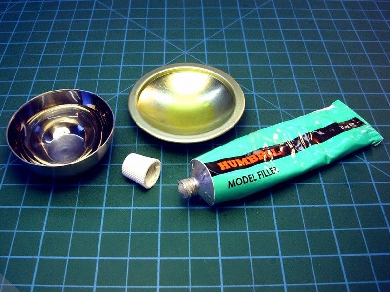
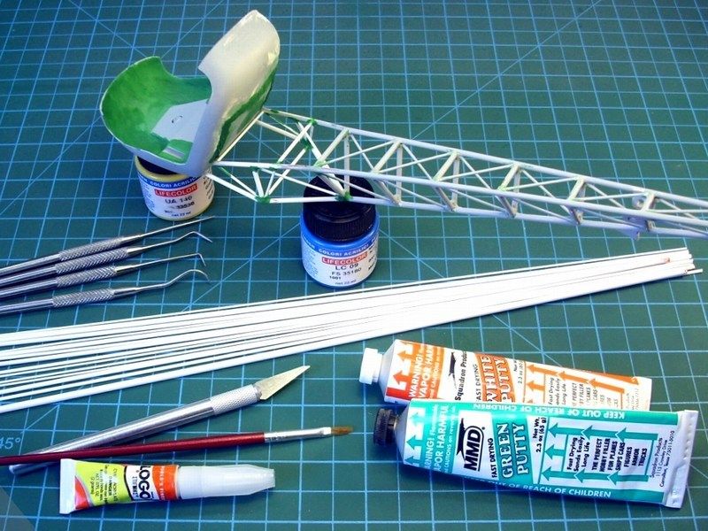
I used styrene plastic card to form it as shown into following pictures to give the basic shape of the canopy. Then, a layer of polyester filler applied on the styrene. The specific polyester filler I used, comes with the proper catalyst which provides a solid rock build and approximately 3 to 5 minutes time window to form it into shape. I prefer to use epoxy putty or polyester filler with fiberglass grains for special purposes, because:
- It becomes solid rock within only few minutes or seconds,
- it does not shrink and does not crack after months or years,
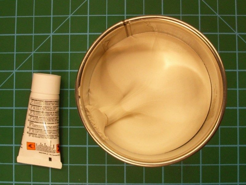
- you can pour to any shape that you want but you need to work fast because as soon as you mix it with catalyst cream approx 5%, you have limited time before becoming solid rock,
- you can also put additional layers of epoxy or polyester filler to build up,
- you can sand it, you can drill it, you can use any type of scale modeling glue, any type of primer or enamel / acrylic paint on it with no problem,
- can be purchased at any good crafts store into 250ml, 500ml, 1lt (comes with a tube of catalyst hardener) or bigger canisters and if you can't find it, fear not and try your local decent hardware store and finally...
- it is cheaper than dirt - estimated prices are £3 to £10 depending the canister size, the quality, if contains fiberglass grains for maximum strength etc.
Keep in mind that the chemical reaction after mixing the polyester filler with the catalyst hardener, produces some heat that possibly effect on thin plastic parts, so test it first before try it on your scale model. I don’t think that the produced heat is more than Fahrenheit 110, but better watch out. Remember that epoxy materials are dangerous when breath or shallow and could result skin, eyes or lungs problems or even cancer when used for long period with no precaution measures. Always keep in mind, that a powerful vacuum system to suck away the epoxy dust should be used all time to keep the workbench area clean while sanding or milling epoxy or resin materials. Using an issued breathing mask and a pair of surgery latex gloves to prevent dust contact with lungs and fingers while sanding or milling epoxy, is also an important matter that you should seriously take care of! My recommendation is to also wear an overall working suit (as I do) to keep your clothes dust free while sanding epoxy. Some people might find it too much, but I wouldn't like to bring epoxy dust & grains from my work bench into living room and my beloved.
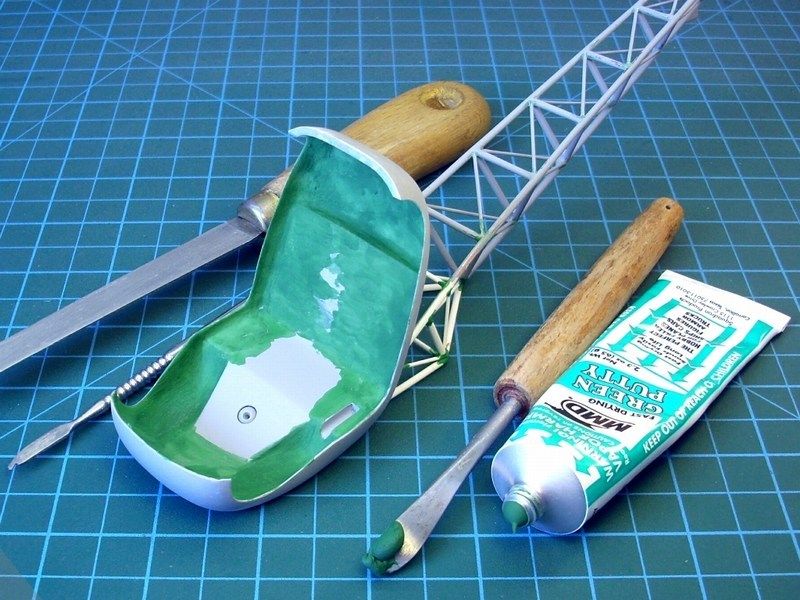
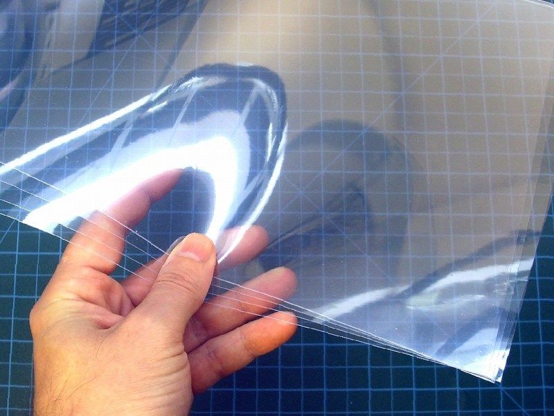
When the basic canopy shape made by styrene sheet, was fully covered by a a thin layer of polyester filler and had enough time to polymerize and get solid rock, I sand it with wet sandpaper to make the cast curved and shiny. To produce a thin-skinned canopy, the polyester part should be vacuum formed. As described into previous chapters, a transparent plastic sheet were pined on a wooden frame, preheated into electric oven and as soon as I noticed that it started drooping down, I vacuum formed it. The clear plastic nicely formed around the canopy cast following the curves & details as planed. Using an X-acto, I removed the formed canopy bubble from the transparent sheet and start adding details, such as canopy's frame. Few drops of cyanoacrylate glue applied on the right spots with great caution. Remember that CA glue does fog the transparent parts and this canopy would not be an exception - that's why I placed some very tiny drops of it, just on few spots.


It’s sad! Obviously, voodoo curses came from the unspeakable dirty Viper snake, got real and the final varnish finishes on the model suffered what the Americans call as FUBAR - F@cked Up Beyond All Recognition.

In brief words, the color layers popped and “cracked” everywhere on the model’s surface, just before the final touch. For some mysterious reason, the color looked peeled off and an unexpected chipping (I would never succeed this by purpose) appeared! The scale modeling accidents committee is expected to investigate the possible reasons within following days, but unconfirmed sources report "pilot’s error" - OK, I made a rookie’s mistake, while using old colors or coat varnish. Meanwhile, the following actions took place:
- Garlic cloves were hanged across the workbench to keep away evil curses, vampires and “snakes” (or those who claim themselves as “snakes”),
- The scale model were covered with a thick layer of ModelStrip product, locked tightly in a plastic bag and left overnight to let the chemical work.
-
CHAPTER VI - Landing gear system construction
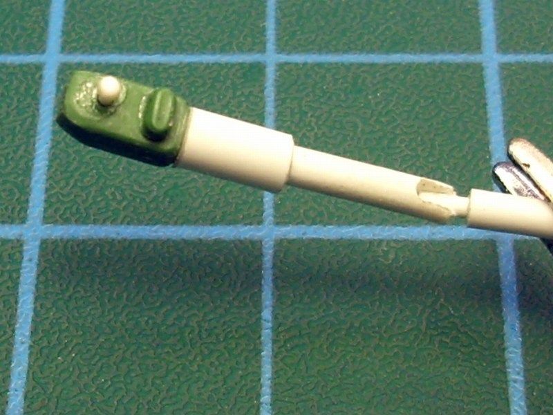
The single seat JT-9 and the tandem seating JT-9T, are available with tricycle landing gear system with a steerable nose wheel or a taildragger version too. For both types, the type of landing gear is based on the placement of the exact CG position, determined after complete weight calculations according the owner/pilot's personal needs. My 1/18 scale model is designed to be equiped with a tricycle landing gear system with a steerable nose wheel. An utility free-spinning tail wheel is also placed, to prevent any accidental damage on tail structure if the autogyro raise nose too high while in ground. Feel free to check the diagrams and images found into my first post of this project, back in page 1.


Using plastic card, sprue, metal wire, resin tires and brakes fit accurately to 1/18 scale diagrams and few unidentified parts found in the sparebox, I build a realistic looking 1/18 scale main landing gear system with absorbers and a steerable nose gear. I stole a nickel plated button from GF's favorite dress (hope she'll never find out where's the missing button or I'm in real trouble), placed it into a plastic tube piece, covered with with transparent plastic card & add some details to simulate the landing light in scale.


Yeah, yeah, yeah... I know! I am a button stealer, but let's admit it! We all prefer less buttons on female dresses.
-
CHAPTER V - "H" shaped tail construction
The Jukka Tervamäki Engineering JT-9T autogyro designed by Finnish engineer Mr. Jukka Tervamäki, is equipped with a twin "H" shaped tail. To build this, I started by rolling flexible styrene sheet around a plastic tube and forming as required to look like the real JT-9T autogyro right side elevator main wing - only 18 times smaller. Following, using the sandwich method (placing one plastic sheet over another), cutting carefully and working extensively with sandpaper to form into desired size and aerodynamic shape, I manage to build the right side stabilizer wing. As you understand, the left side elevator wing, the stabilizer and rudder, will be stripped in a way to show the airframe aluminum skeleton.


-
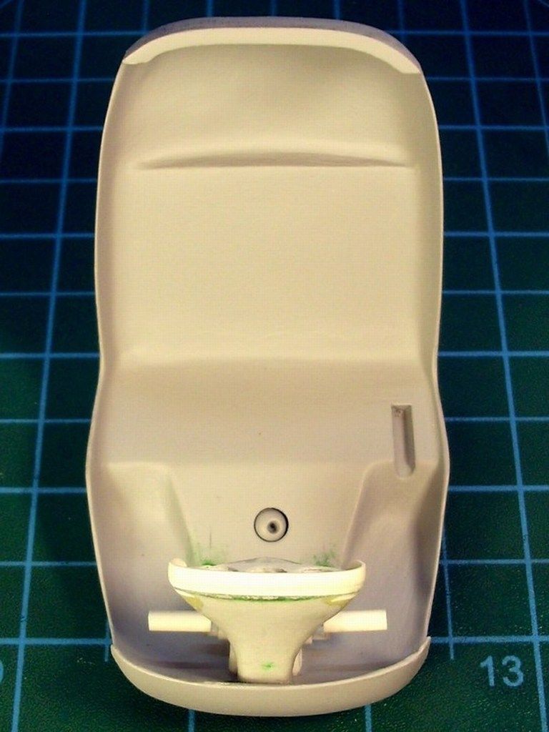
Remember the previously mentioned wooden picture frames, found at the local IKEA store for only 1€ each, securing the styrene plastic sheet to be vacuum formed? I kept these thin plexiglass plates, to use them as required. Continuing the cockpit construction, I had to build the rear cockpit cover, so I placed the autogyro model upside down facing a glass surface, I boxed it by placing the thin plexiglass plates around it, securing in place with modeling clay for kids. Then, I removed the scale model carefully, leaving space between these thin plexiglass plates. Wet white plaster mixture, applied into the gap, between the thin plexiglass plates to fill the area. When the first layer of thinned plaster was dry and hard enough, two or three extra layers of white plaster followed to finally build the basic cast. Keep in mind that adding salt into wet plaster mixture, reduce the plaster's hardening time and adding vinegar into wet plaster mixture, extend the plaster's hardening time.


When the plaster cast was dry and hardened after few hours, I removed the modeling clay for kids and the thin plexiglass plates. The white plaster cast got shaped into proper dimensions but cutting it with saw, filling with tiny quantities of modeling putty added to close minor scratches and pores on white plaster cast surface, dry sanded and finally sprayed overall with gloss shiny coat.


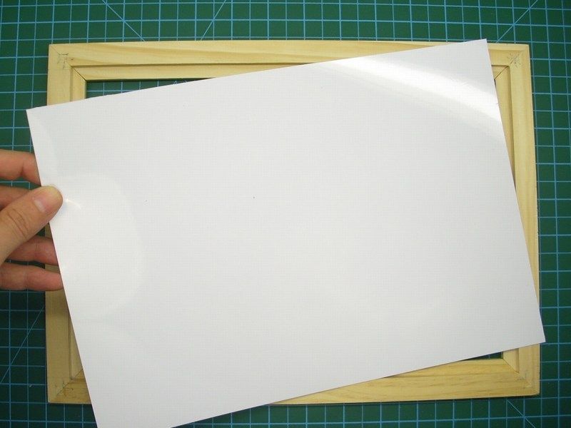
Because I was planning to use smaller wooden frame to secure the styrene plastic sheet (the piece to be vacuum formed is too small, there is no need to spend big plastic card), I had to close the outer holes on the hardboard high-density fibreboard plate. To do so, I cut a plastic bag in shape and covered as required the desired area. I pined a styrene plastic sheet on the wooden frame, insert it into the preheated electric oven as described before and as soon as I noticed that the plastic started drooping down, I removed it on the vacuum former plate, while the vacuum cleaner was already plugged & switched on. The plastic nicely formed around the plaster cast and here is how it looks like.


As long as the piece looked satisfying to me, I removed the formed plastic from the styrene sheet with a new Nr 11 surgical blade on my cutter, test fitting on the scale model and later start adding internal detail.


I placed the rear cockpit’s cover in place and secure it with just one or two drops of CA super glue. Then, using a small pencil, I defined the exact line that the rear cockpit cover should be cut in order to let the inside structure visible. Using the mini Dremel tool, I cut and removed the left half part, in a way to look kind artistic.


 My good friend Demitris “Jagdpanther” Pravinos, who is a WWII German tanks specialist scale modeler, sent me about five hundred (!!!) cups he found and looked ideal to use them for mixing colours, modeling putty etc. Few drops of nitrocellulose lacquer thinner and just a little amount of Humbrol modeling putty, were more than enough to prepare a nice liquid mixture to apply on the rear cockpit cover surface, to ensure that little tiny scratches would disappear.


 Few hours later, soft sanding and a quick airbrushing with white color to make mistakes, scratches etc become easy to spot, the rear cockpit cover was finally ready.
-
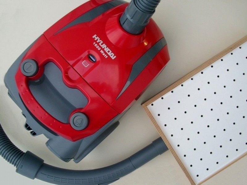
To produce a thin-skinned right side fuselage, the polyester part, must be vacuum formed. That means, that I should build from the beginning a new vacuum chamber box. Vacuum forming is a very simple technique that can produce thin-skinned parts of various forms. I mainly used vacuum forming for producing a variety of components for scale modeling. Basically, it’s all about a box with a connection for your household vacuum cleaner and a series of holes in its top plate and try keeping the box airtight at the seems. The basic idea is to build from scratch or buy one if you find something similar, a wooden box like the one I present. I found the following item (which supposed to be a display box or something, for placing plants, coloured sand & stuff inside and make them look nice as a decoration on the wall) at my local IKEA. Looking exactly like what I've been searching for and considering the low price (not more that 5€), I preferred to buy it instead of building a new wooden box like this from scratch. As you can see at the following pictures, I removed the glass, applied a generous layer of water based white glue for wood (which becomes transparent when it dries) across the inner joints, to keep them as air tight as practical and be sure that no air could escape from there.


Visiting my local Dexion store (shelving & racking solutions), I got a 135x85cm hardboard sheet (more than 1 square meter area) for 8€. This is actually a louvred panel, designed to stand against the wall and accept hooks & spigots for easy storage of everything from belts and hose clips to spools and reels and all kinds of other parts. I cut a piece on the right dimensions and slide it into rail to test the fitting. The 35x25cm top plate has many 4mm wide holes to allow air to be pulled through them. The locations of the holes are not important, and can be also drilled by hand using a hand held drill. Just make sure that they are fairly close together. This top plate should be pretty sturdy to hold the subject being duplicated. I made mine from hardboard high-density fibreboard plate, but I have seen them made out of aluminum too. The top plate finally was slided into inner rails - otherwise it would be screwed down with flat head wood screws. Be sure to countersink the holes to make the heads flush with the top surface. I also epoxied it down, just to also make it a little more air tight. As long as 1 square meter area hardboard plate, is more than enough for me and can be used to build more than 5 or 6 vacuum forming device plates, I gave the rest to other fellow modelers who are also interested to build one.


Using the proper Black & Decker saw tool, a 34mm wide hole was drilled through the side of the box to facilitate a vacuum cleaner fitting. Luckily, last week I found a real bargain at the local Media Markt store and I bought a 1600W brand new Hyundai HVC-6003 vacuum cleaner for 15€ only. I decide to use in this vacuum cleaner into my hobby room and for vacuum forming purposes only. I cut a plastic tube - you may have an old piece of an old tool laying around the house or you can purchase one at a vacuum cleaner shop - and fix it with Bison glue for PVC on the box. Then, I screw a wooden stick into the box's center to prevent any possible hardboard plate bending because of vacuum and finally slide the high-density fibreboard plate through the rails to close the box. I sealed everything with white water based glue for wood. The following pictures show the vacuum chamber box building progress and where you will plug in your household vacuum cleaner.


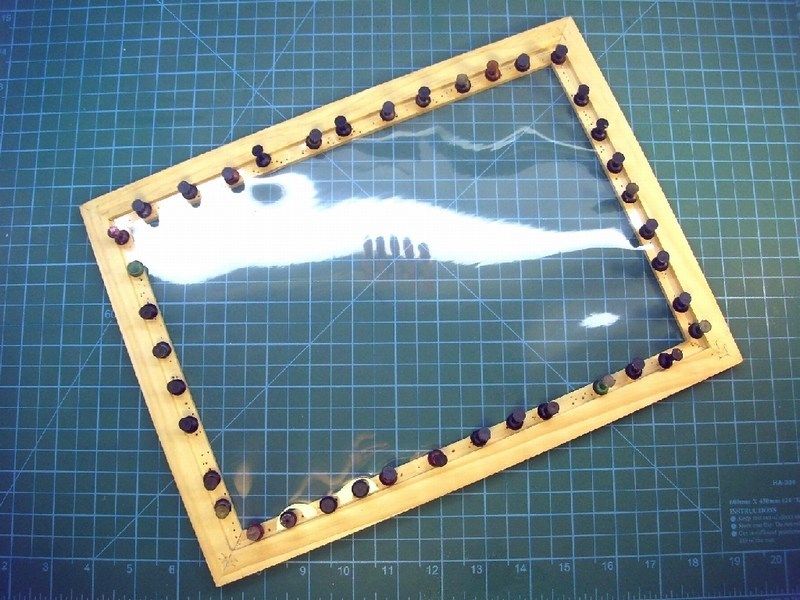
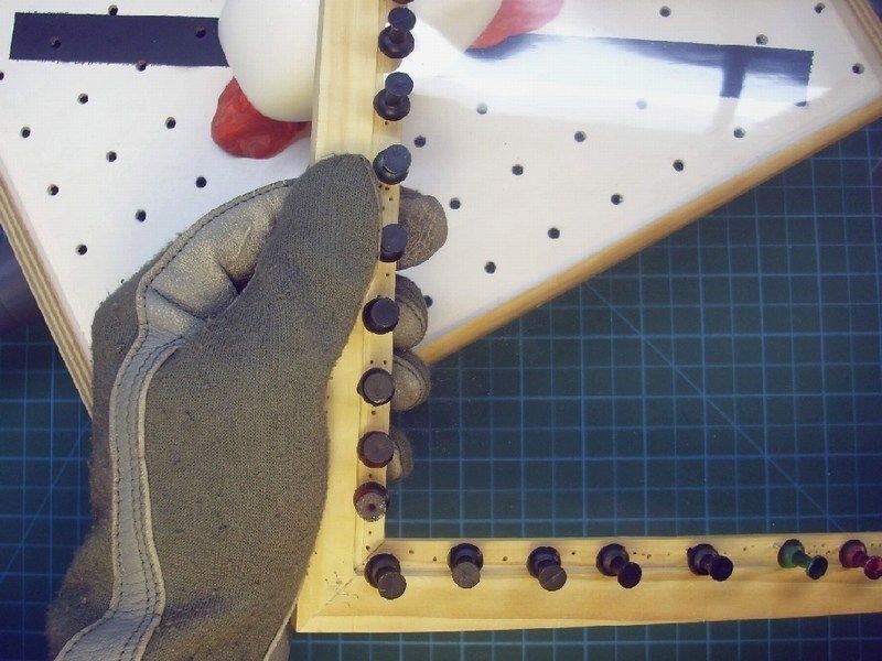
I also got few wooden picture frames found at the local IKEA store for only 1€ to 3€ each (depending size) and few metal made spring clamps for 0.5€ each, to use them for steady & tight styrene sheet holding while being heated. Avoid plastic clamps, because they might melt while in the oven. It's also possible to build clamping plates made by aluminum sheet and the two plates are clamped together using screws and wing nuts. Aluminum clamping plates is better but might cost more. For these, you are only limited by the size of the oven you have.


Heat your electric oven to some predetermined level, whatever works and start heating the plastic sheet. I have never tried this with a gas one, so use caution if you do! Once the plastic gets warm, you’ll notice it will droop down. When you think the plastic is soft enough, fire up the vacuum cleaner, take the plastic from the oven and thrown the sheet on the vacuum former. The plastic will nicely form around the moulds. This will take some practice and sometimes a mould tips over or the plastic won’t form properly over the mould (folding around edges). This is also the part where I should warm you that you can burn your fingers - I highly recommend Nomex Aramid flame resistant MilSpec gloves, which I personally use for the job. I buy large plastic styrene 50x30cm sheets for 0.5€ to 1.5€ each (depending width), not the more expensive styrene by Evergreen. When an attempt fails, I usually throw the sheet back in the oven and start again. I’ve included some pictures above, but remember, this description of how to make a vacuum form is only a guide. You can make yours with many variations to suit your own needs and from various materials. Once you have the machine, you can make all kinds of things. You can make a lot of aircraft wings, airframe, panels etc out of a sheet like that. You can make the master molds from basswood, epoxy, polyester etc and the parts you make depend on how accurate the master molds are. The molds must be as accurate and detailed as necessary to achieve the results you are after.
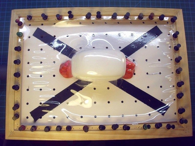
I thought as good idea to try something different this time and I did not use the metal made spring clamps to hold steady & tight the styrene sheet on the wooden frame and experiment with thumbtacks. I placed the frame into the preheated electric oven and I wait few critical seconds watching the plastic start heating. As soon as I noticed that it started drooping down, I removed the frame while wearing Nomex Aramid flame resistant MilSpec gloves, to prevent finger burns. While the vacuum cleaner was already switched on, I placed the wooden frame with the pined plastic sheet on the vacuum former plate. The plastic nicely formed around the “virtual” airframe mold... and voila!


Note: If I leave the styrene plastic sheet in the electric oven a few more seconds and the plastic was softened further, I would avoid the shrinkage of the plastic that appears in the lower right corner of the original cast. The fact that the plastic could heat up even more, evidenced by the fact that one or two thumbtacks were pulled. But as long as my point of interest (the whole right side of the fuselage and a bit from the bottom side) formed nicely around the mould, the result fully satisfied me and I didn’t try a new vacuum forming.
Using my X-acto blade, I removed the formed fuselage from the styrene sheet and test fitting on the autogyro scale model airframe. Few drops of CA super glue applied on the right spots across the fuselage joints to make the contact secure, did some light sanding on the fresh produced thin-skinned right side fuselage to eliminate some tiny marks and as you can see at the following pictures, the nearly transparent result is more than realistic to scale and completely satisfies to me.


-
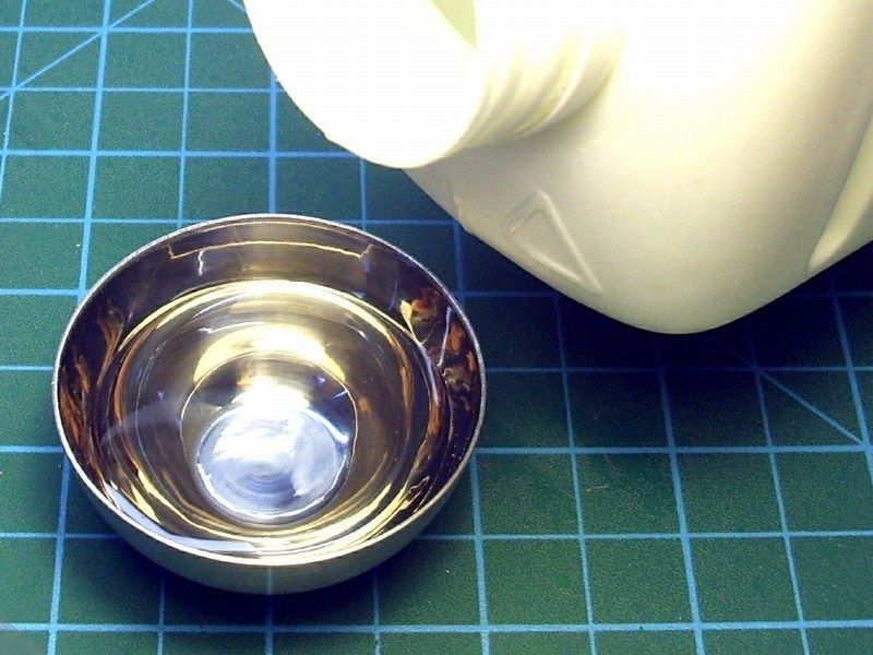
I add some grams of plaster powder and few drops of water with a syringe into a soft rubber cup to make the right mixture. Materials like plaster, start as a dry powder that is mixed with water to form a paste which liberates heat and then hardens. Unlike mortar and cement, plaster remains quite soft after drying and this characteristic make plaster suitable for the job. Keep in mind that adding salt into wet plaster mixture, reduce the plaster's hardening time and adding vinegar into wet plaster mixture, extend the plaster's hardening time. When the first layer of thinned plaster applied on the plastic bag was dry and hard enough, a second thin layer of plaster was applied to form a basic strong cast. The basic idea, is to let the plaster follow the airframe details, accurate on scale and as thin as possible trying not to apply extra stuff where is no needed.


Found at my local supermarket and got for only 0.5€, the following modeling clay for kids. Some scale modelers, use this material to border camouflage patterns while airbrushing. I pick a piece, mold it into snake alike formation and placed it across the airframe to border the wet plaster flow - yellow color for up and purple color for bottom airframe side.


When I finally enclosed the right half JT-9T scale model into plaster, I left it few hours to get harden in order to be sure that the cast wouldn't break when I would try to remove the scale model from inside. Meanwhile, I took the soft rubber cup which I used to make the plaster mixture, squized it to break the last hardened plaster left inside, so it would be easier for me to clean it afterwards and prepare it for any future mix. That's the reason this soft rubber cup were used for.


As soon as the plaster cast was dry and hardened, I removed the the modeling clay I used for bordering the plaster flow and pull the enclosed JT-9T scale model airframe away, gently. Brushing the area with an old tooth brush, I removed unwanted dust or small broken plaster pieces.


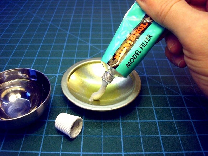
Johnson's baby oil or similar is well know to anybody who have children in house. If you don't have children yet, ask your girlfriend - all girlfriends have a tiny bottle in their cosmetics drawer. If you don't have a girlfriend, close this web page, shut down your PC/laptop and get your feet out of house to meet one! Scale modeling is nice, but feeling a nice female next to you is much better. Continuing with the project, thin layers of vaseline based mixtures can be also used instead of baby oil to apply with a soft brush as a segregative material between the plaster cast and generous quantities of polyester filler applied on the plaster cast.


The specific polyester filler I used, comes with the proper catalyst which provides a solid rock build and approximately 3 to 5 minutes time window to form it into shape. I prefer to use epoxy putty or polyester filler with fiberglass grains for special purposes, because:
- It becomes solid rock within only few minutes or seconds,
- it does not shrink and does not crack after months or years,
- you can pour to any shape that you want but you need to work fast because as soon as you mix it with catalyst cream approx 5%, you have limited time before becoming solid rock,
- you can also put additional layers of epoxy or polyester filler to build up,
- you can sand it, you can drill it, you can use any type of scale modeling glue, any type of primer or enamel / acrylic paint on it with no problem,
- can be purchased at any good crafts store into 250ml, 500ml, 1lt (comes with a tube of catalyst hardener) or bigger canisters and if you can't find it, fear not and try your local decent hardware store and finally...
- it is cheaper than dirt - estimated prices are £3 to £10 depending the canister size, the quality, if contains fiberglass grains for maximum strength etc.
Keep in mind that the chemical reaction after mixing the polyester filler with the catalyst hardener, produces some heat that possibly effect on thin plastic parts, so test it first before try it on your scale model. I don’t think that the produced heat is more than Fahrenheit 110, but better watchout. Remember that epoxy materials are dangerous when breath or shallow and could result skin, eyes or lungs problems or even cancer when used for long period with no precaution measures. Always keep in mind, that a powerful vacuum system to suck away the epoxy dust should be used all time to keep the workbench area clean while sanding or milling epoxy or resin materials. Using an issued breathing mask and a pair of surgery latex gloves to prevent dust contact with lungs and fingers while sanding or milling epoxy, is also an important matter that you should seriously take care of! My recommendation is to also wear an overall working suit (as I do) to keep your clothes dust free while sanding epoxy. Some people might find it too much, but I wouldn't like to bring epoxy dust & grains from my work bench into living room and my beloved.
When the plaster cast used as a "negative image" of the right side fuselage, was filled with a thick layer of polyester filler and had enough time to polymerize and get solid rock, it was sunk into water and stayed wet for few minutes, in order to get moistened, become soft and let the right side fuselage replica made of polyester be removed easily.


…if you still read this, you are a father already or have a girlfriend.
-
CHAPTER IV - Right side fuselage construction
As I said at the beginning of this thread, I decide to make the JT-9T building look more interesting and show the model in a way that airframe should look like cutaway side opened and let cockpit detail be easily observed. THIS artistic diagram gave me the idea and that would be a nice opportunity to present my way to do it. To do so, I decide that a solid rock one-piece "negative image" cast of the right side fuselage should be made of plaster first and then build a right side solid replica made of polyester, epoxy or resin. This replica - virtual fuselage, would be the basic line to create a thin right-to-scale fuselage surface.
My local newsagent, usually wraps my newspaper and magazines into a plastic bag, which sometimes I use to collect the trash. This time, I decide to use the plastic bag in a completely different way. I cut free-hand few pieces of plastic, keeping in mind to make them longer & wider than the autogyro scale model dimensions. Using duct tape, I stretched the plastic bag across the airframe, in a way to simulate the full right side and half bottom fuselage surface, trying not to leave any visual wrinkles or marks.


-
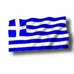
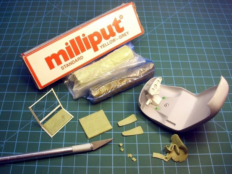
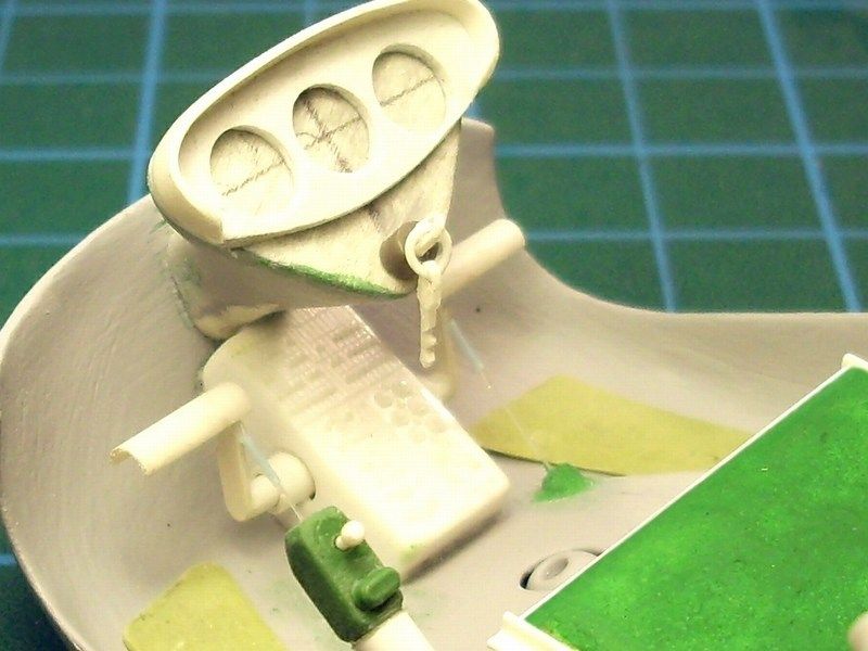
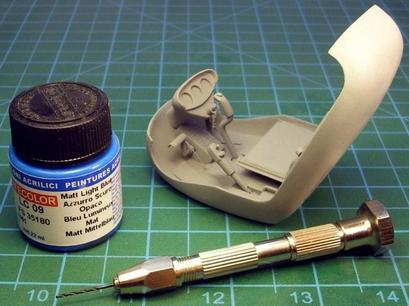
The instrument panel is made of standard Milliput epoxy putty, which is popular among modelers and also useful in countless household & restoration applications. Switch board, tail rotor control pedals, cyclic control stick and collective lever are made of drilled & cut styrene plastic card. Wiring is made of 0.20mm diameter fishing line.
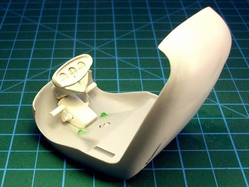
Using styrene plastic card, I cut the basic lines to form into the student pilot’s seat. The dimensions and the shape are based on actual Bö-102 pictures. Standard Milliput epoxy putty was used to simulate the pillow. Finally, the cabin sprayed with Humbrol light grey acrylic primer to show up any possible scratches that I did not spot so far..
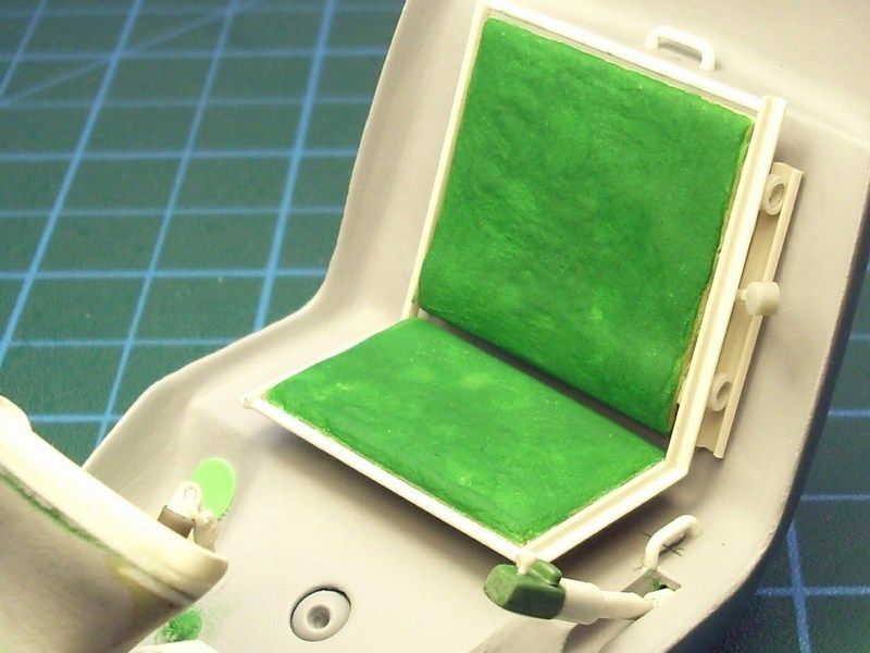
Please keep in mind, that despite the fact that only 18 Bö-102s were produced, the available pictures show that there were many and obvious differences between them in several places. Different seats (some of them were not even seat), different cockpit and cabin colour, different fuel tank canisters, different tail boom frame construction, different landing pad and some of the Bö-102s, were not even equipped with landing skids. So, don’t be surprised if you witness differences.
-
CHAPTER III - Instrument panel & cockpit construction
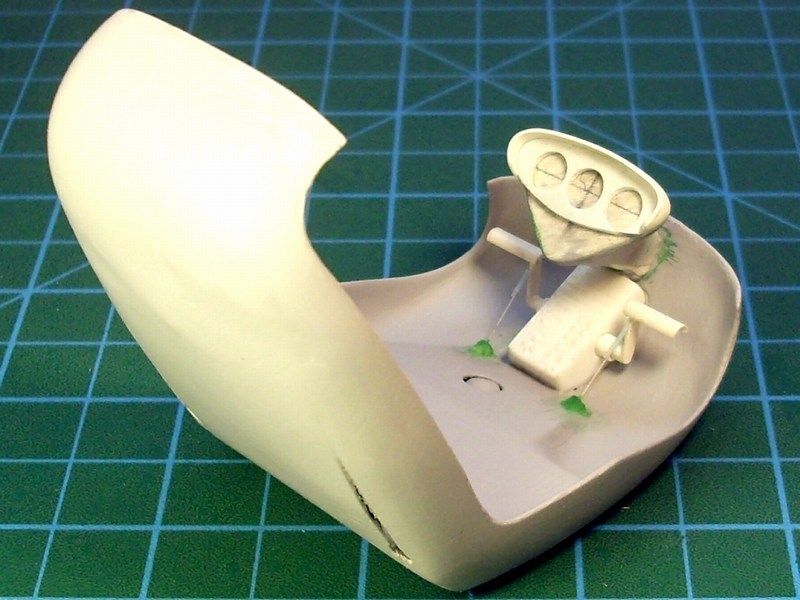
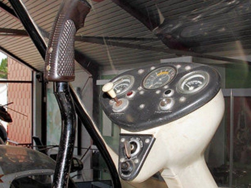
The original Tervamaki Engineering JT-9T autogyro instrument panel is not what you would call as "glass cockpit". Actually it does only have just the basic instruments in cockpit to provide the pilot with information about the flight situation, such as height, speed and attitude. Since the JT-8T autogyro is not designed to fly in conditions of poor visibility or night, the main information is available from visual reference outside the aircraft. Of course, many pilots who are lucky enough to own an autogyro, they might add more sophisticated equipment such as CFT screens, HSI - Horizontal Situation Indicator to follow VOR signals, GPS screens, VHF/UHF radio, replace the heading indicator by a GPS-driven computer with wind and glide data etc. The basic instrument panel is consist by:- An altimeter indicator,
- an ADI - AttituDe Indicator,
- an ASI - Air Speed Indicator,
- a VSI - Vertical Speed Indicator,
- a fuel quantity indicator,
- an engine RPM tachometer,
- an analog clock and
- a magnetic compass.
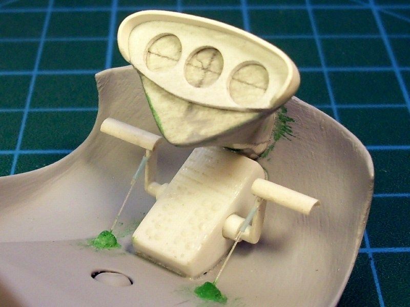
I started by cutting the main panel shape in plastic and drilled the gauges positions. Using the Corel Photo Paint, I created a coloured sketch of the instruments, copy & paste the image into a MS Word new file and print it on a simple A4 page. Meanwhile, I add some detail on the instrument panel, such as rivets made by streached sprue inserted in drilled out holes, knobs etc.


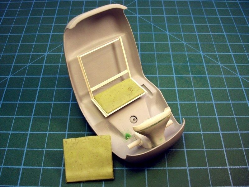
Using styrene plastic card, I cut the basic lines to form into the two simple seats. The dimensions are based on the basic 1/18 scale JT-9T two-seat trainer blueprint line diagram as seen HERE. On the real JT-9T autogyro, these simple seats are made of hard plastic, fiberglass or even wood sheet and buckram covered home made pillows are placed to provide comfort. These seats are fixed on metal rails, running across the cockpit floor connected with main skeleton, to ensure seat's secure installation.


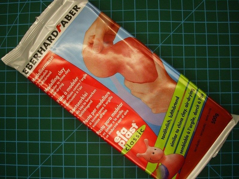
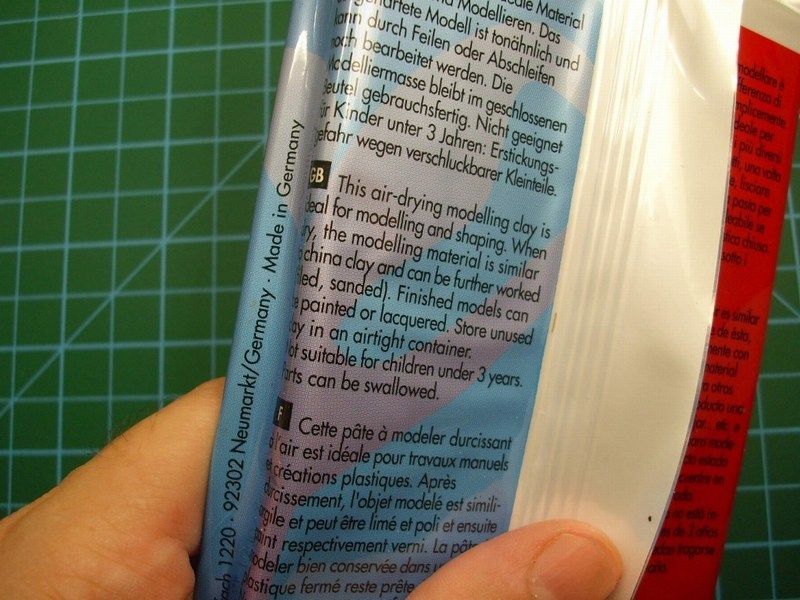
For many years, I was used to form aircraft seat pillows with Milliput epoxy putty, which is popular among modelers and also useful in countless household & restoration applications. But, while I was in a supermarket last week, I found the following item and I thought that it could be nice to try it and start experiment with this material. It's an air-drying modeling clay ideal for scale modeling and shaping. According to the instructions, it can be easily formed into shape, become solid rock withing few hours, re-filled or sanded if neccessary and painted or lacquered. That sound quite good to me and similar to the well known Milliput epoxy putty, with the only difference that the 500g air-drying modeling clay pack cost only 1£, instead of 100g Milliput epoxy putty which cost 5£. That makes the new found air-drying modeling clay, about 25 times cheaper than Milliput epoxy putty and that's a good reason for me to give it a chance.


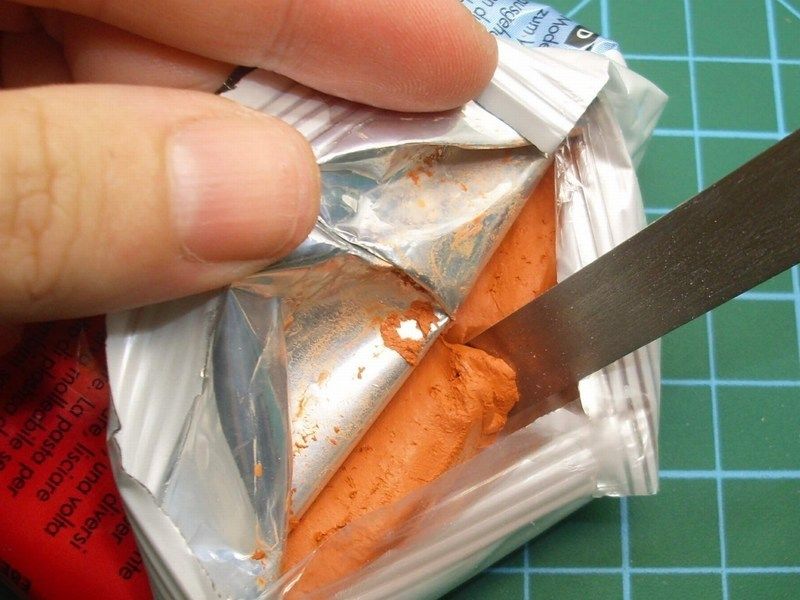
Picking a small quantity with a metal spatula and applying the air-drying modeling clay on the seats, it felt too soft and very easy to spread the material nicely to simulate pillows realistic way. I didn't want to care too much and try forming and shaping the clay, because I was planning to cover the sculpted pillows with wet soft paper to simulate the buckram covered pillows. After all, I had no idea how much available time I had, before the material start becoming hard and difficult to handle.


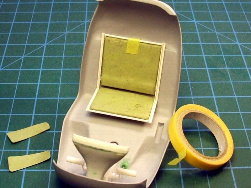
 Toilet paper is not only for the obvious purpose but can also be useful for scale modeling. I used ordinary toilet paper, cut it to shape and dress the seat pillows made by air-drying modeling clay, to look more realistic and simulate the buckram covers. Water based white glue for wood, which becomes transparent when it dries, is just the right for the job. So, I opened a 500 grams canister bought for 2€ only, pick a small quantity, add just few drops of water with a syringe into a small metal container to make the right mixture and finally I formed the paper on the pillows with a wet brush, into the desired shape. Because the mixture is enriched with water based glue, the soft toilet paper becomes hard when the water dries.


-
CHAPTER II - Instrument panel & cockpit construction
As written before, the Bölkow Bö-102 Helitrainer was a helicopter training aid that was developed and built to allow a student pilot controlled experience of helicopter systems. That's why the cockpit panel was so simple, that a 5yo child could operate. Three gauges on the instruments panel, few switches, a cyclic control stick and a collective. That's all! After all, it was not designed to fly, but only give a helicopter hover & flight feeling.
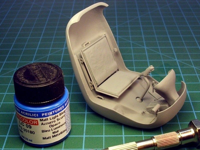
I started by cutting the cockpit’s floor shape in styrene and shape it as required to fit into the cabin.
Once I tried test fitting, I discovered that there was some tiny gaps between the cockpit's floor and the cabin. These gaps, should be filled. So, "mind the gap"!

To do so, some quantities of liquid modeling putty, filled between the gaping surfaces. In order to make the putty liquid and let it spread naturally and fill the tiny gaps, I mixed Humbrol putty with lacquer thinner. Because the lacquer thinner is volatile, the liquid putty mixture took about 45 minutes to get fully dry and be safe to sand - carefully of course. If you follow this method, be sure that you mix the lacquer thinner and the modeling putty into a metal or glass plate / canister, because the most plastic materials cannot stand it and melt. For this reason, keep in mind to use just the essential lacquer thinner quantity, in order to remain the mixture in liquid form, as it is presented at the following pictures.
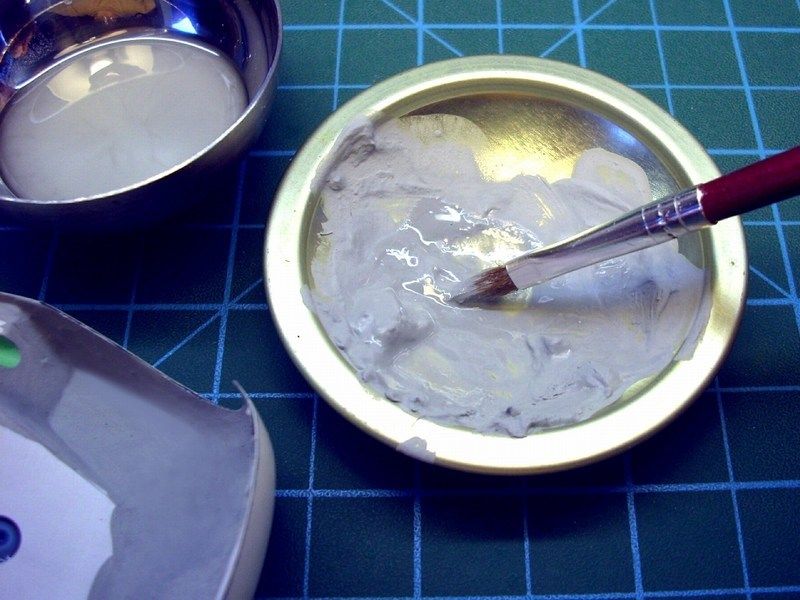
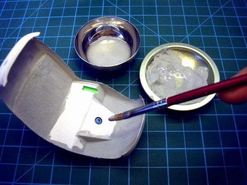
The last liquid putty layer was applied using the Squadron MMD green putty instead of the general purpose Humbrol, because I personally find it better for final smooth details.
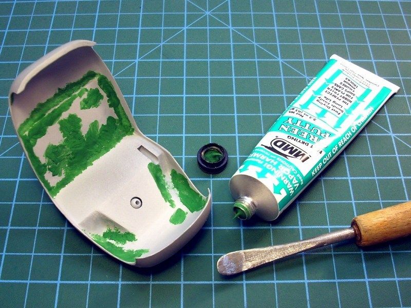
The Squadron MMD green putty, also used to create some minor details on the cabin’s back side, where the tail boom frame (tail boom construction will be explained later) joints will be later fitted. At last, I tried many test fit attempts with the tail boob, to ensure that I’ll not face any unpleasant surprises later.
An additional green putty layer applied and the cockpit surfaces carefully sanded to look as smooth as possible, before sprayed with Mr. Surfacer 1200 as a final touch.
-
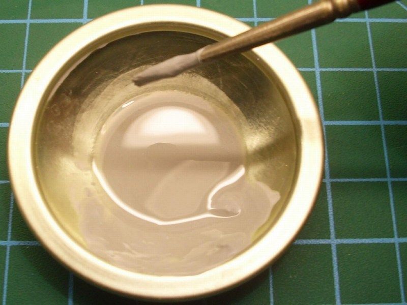
As I personally believe that following simple techniques and sometimes unconventional methods, result in superior effects, I usually do not use enamel or acrylic paint to wash, because I feel risky when applying the paint mixture and let it run. I prefer an easier technique that can be undone if the results are poor - that makes it the perfect technique. I use hard chalk pastels to wash (NOT oil pastels). The hard chalk pastels, look like a teacher would use on the blackboard in school. Do not use the soft oil pastels that artist use to draw on paper. The hard chalk pastels are easy to find in a variety of colours into your local art store or maybe Wal-Mart if in US or ASDA if in UK.
To do the wash, I use an X-acto knife, a small metal or plastic container, an old brush, dish washing soap and a bit of water. Begin by scraping some chalk powder from the side of the chalk pastel stick, carefully put this chalk powder into the small container and add a tiny amount of water and stir. It is important to add a tiny amount of water in order to make the mixture look like mud - not like soup! For this reason, I use a syringe to add just few drops on the hard chalk pastel powder and I stir using the old brush. Because the chalk powder doesn't mix well with the water, a drop of dish washing soap is needed to break the surface tension of the water and also acts as a "glue" to help the chalk powder stick to the model.


Once the chalk is fully dissolved into the water/soap mixture it is time to "paint" this mixture onto the model's engine. "Painting" the mixture is simple - just apply it anywhere it is needed to darken recessed detail. The mixture can be applied carelessly, because any mistakes can be completely removed and redone. Once the chalk wash dried, I rubbed off the high spots with a slightly damp dry (not wet) Q-Tip cotton swab (Kleenex papers can be also used) and I wiped the dark color from the areas should be light & shinny. The high spots were cleaned to the SNJ bare metal finish and the low spots were left black. I did the chalk wash on the engine in under 30 minutes which makes it a very quick and effective technique.


Some of the wash mixture is re-applied and the wash being wiped completely out of the narrow points. If you follow this method, it is adviced to not rinse out the wash container till you are finished this job. You will probably be touching up certain spots a few times, so it helps if you're not mixing up a new chalk mixture each time because you kept cleaning out your container of the chalk wash mixture. As soon as I paint the electric cables, the oil or diesel lines etc, I repeated the the wash process with lighter colors where needed. Using micro cotton batons found into cosmetic shop for less than 1£, I applied some red, orange, purple & brown chalk pastel powder on the engine's chrome excaust, to make it look overheated. I repeated the weathering process until it satisfied me and finally I sprayed a clear coat to seal the chalk powder on the engine.


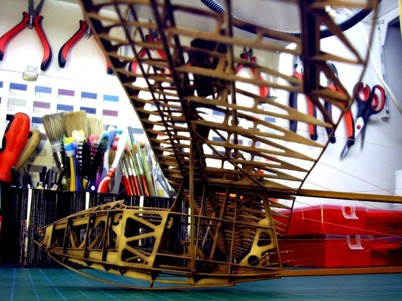
The scale model building, cost me almost nothing and took about 2 evenings work so far. I also send some pictures of my secret hideout / hobby room while scratchbuilding the 1/18 scale JT-9T autogyro model. Click on the first image to enlarge hi-res 180 degrees panoramic picture.


-
CHAPTER II - Diesel engine building & painting
Setting as a task to build the model in a way that airframe look like cutaway side opened with cockpit and engine bay details visible, I should also leave the engine's cover opened. that offcourse means that a diesel engine building from scratch is something I couldn't easily avoid. Using plastic card, sprue, metal wire and unidentified parts found in the sparebox, here is my effort to build a realistic 1/18 scale engine.


After connecting with superglue the main elements, the electric cables and oil or diesel lines etc on engine's shape, I airbrushed it with enamel mat white color as a base coat, using high air pressure and spraying from distance to develop a pore surface and help silver & aluminum paint establish easier on plastic or metal engine's parts. As soon as the enamel mat white color seemed dry enough, a mixture of silver and aluminum paint sprayed on the engine and let about 24hrs to dry before trying to wash it with darker colors.


-
In my previous WIP article about the 1/18 scale Jukka Tervamäki Engineering JT-9T autogyro project, I explain in a very detailed manner, how to build a vacuum forming device, starting from scratch and using materials that can be found in your local super market. If you are not aware how to build a scratchbuilt vacuum form, please feel free to read it as I described and it might be useful for you.
Heat your electric oven to some predetermined level, whatever works and start heating the plastic sheet. I have never tried this with a gas one, so use caution if you do! Once the plastic gets warm, you’ll notice it will droop down. When you think the plastic is soft enough, fire up the vacuum cleaner, take the plastic from the oven and thrown the sheet on the vacuum former. The plastic will nicely form around the moulds. This will take some practice and sometimes a mould tips over or the plastic won’t form properly over the mould (folding around edges). This is also the part where I should warn you that you can burn your fingers - I highly recommend Nomex Aramid flame resistant MilSpec gloves, which I personally use for the job. I buy large plastic styrene 50x30cm sheets for 0.5€ to 1.5€ each (depending width), not the more expensive styrene by Evergreen. When an attempt fails, I usually throw the sheet back in the oven and start again. Once you have the machine, you can make all kinds of things. You can make a lot of aircraft wings, airframe, panels etc out of a sheet like that. You can make the master molds from basswood, epoxy, polyester etc and the parts you make depend on how accurate the master molds are. The molds must be as accurate and detailed as necessary to achieve the results you are after. As you see in the following pictures, I tried white and clear styrene sheets too, in order to build the cabin by white styrene and the bubble canopy by clear.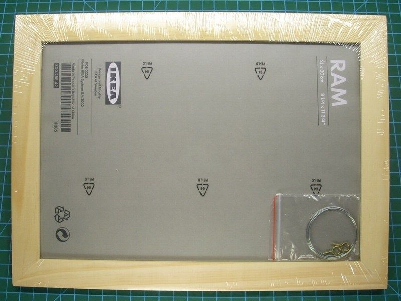
I placed the frame into the preheated electric oven and I wait few critical seconds watching the plastic start heating. As soon as I noticed that it started drooping down, I removed the frame while wearingNomex Aramid flame resistant MilSpec gloves, to prevent finger burns. While the vacuum cleaner was already switched on, I placed the wooden frame with the pined plastic sheet on the vacuum former plate. The plastic nicely formed around the “virtual” airframe mould... and voila!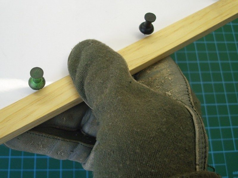
Using my X-acto knife, I removed the formed cabin pieces from the styrene white or clear sheets and tried some test fitting on the cast.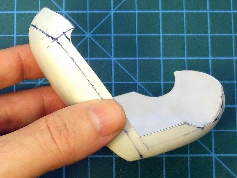
-
 1
1
-
-
CHAPTER I - Cabin & bubble canopy construction
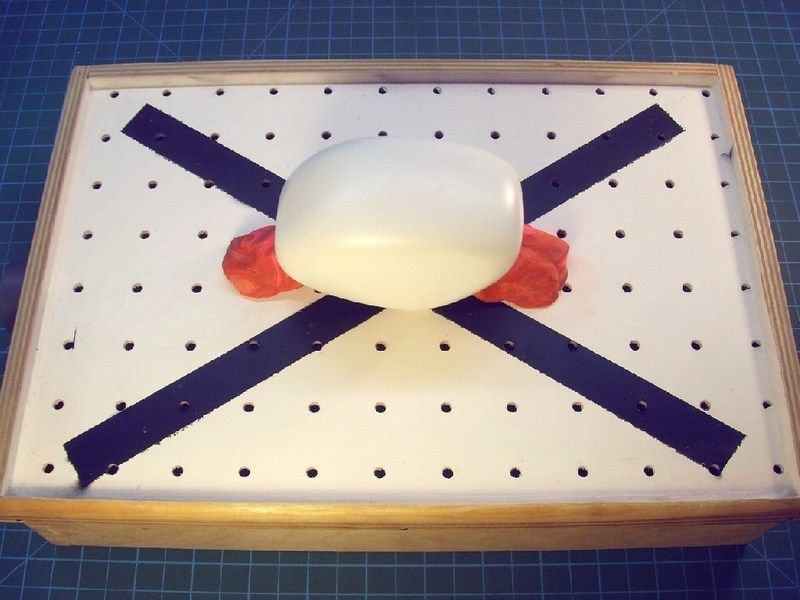
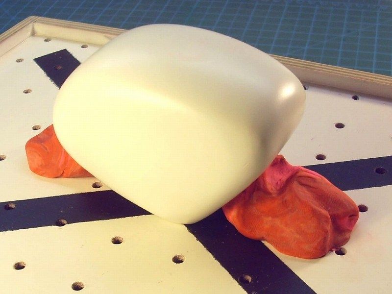
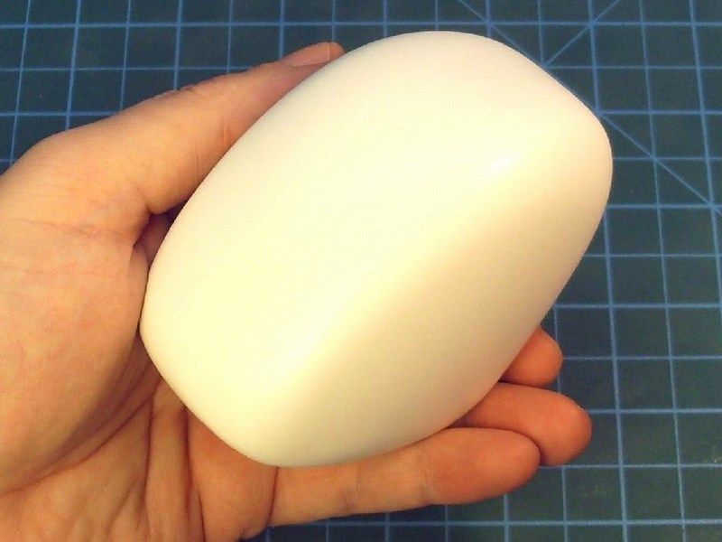
To produce a thin-skinned, right-to-scale cabin, a solid rock one-piece "image cast" of the bubble typed cabin should be made of modeling clay & epoxy first and then try to reproduce a copy by vacuum forming the image cast. Using the following modeling clay item, found in my local supermarket. It's an air-drying modeling clay ideal for scale modeling and shaping. According to the instructions, it can be easily formed into shape, become solid rock withing few hours, re-filled or sanded if necessary and painted or lacquered. That sound quite good to me and similar to the well known Milliput epoxy putty, with the only difference that the 500g air-drying modeling clay pack cost only 1£, instead of 100g Milliput epoxy putty which cost 5£. That makes the new found air-drying modeling clay, about 25 times cheaper than Milliput epoxy putty and that's a good reason for me to give it a chance.
I formed the basic shape of the bubble typed cabin, by picking small quantities of this modeling clay with a metal spatula and applying the air-drying modeling clay. It felt too soft and very easy to spread the material nicely. I didn't want to care too much and try forming and shaping the clay, because I was planning to add epoxy putty and sand to make a nice shinny finish. After all, I had no idea how much available time I had, before the material start becoming hard and difficult to handle.
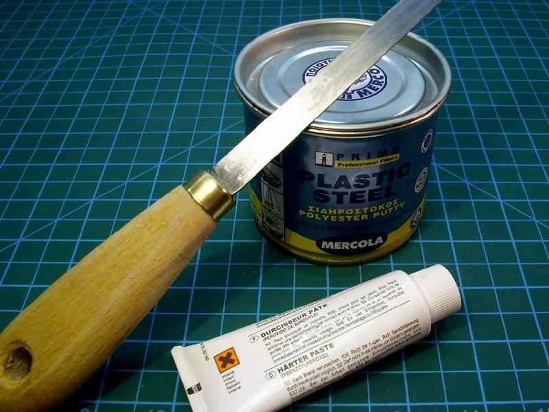
The specific polyester filler I used to apply over the clay, comes with the proper catalyst which provides a solid rock build and approximately 3 to 5 minutes time window to form it into shape. I prefer to use epoxy putty or polyester filler with fiberglass grains for special purposes, because:
- It becomes solid rock within only few minutes or seconds,
- it does not shrink and does not crack after months or years,
- you can pour to any shape that you want but you need to work fast because as soon as you mix it with catalyst cream approx 5%, you have limited time before becoming solid rock,
- you can also put additional layers of epoxy or polyester filler to build up,
- you can sand it, you can drill it, you can use any type of scale modeling glue, any type of primer or enamel / acrylic paint on it with no problem,
- can be purchased at any good crafts store into 250ml, 500ml, 1lt (comes with a tube of catalyst hardener) or bigger canisters and if you can't find it, fear not and try your local decent hardware store and finally...
- it is cheaper than dirt - estimated prices are £3 to £10 depending the canister size, the quality, if contains fiberglass grains for maximum strength etc.
Keep in mind that the chemical reaction after mixing the polyester filler with the catalyst hardener, produces some heat that possibly effect on thin plastic parts, so test it first before try it on your scale model. I don’t think that the produced heat is more than Fahrenheit 110, but better watchout. Remember that epoxy materials are dangerous when breath or shallow and could result skin, eyes or lungs problems or even cancer when used for long period with no precaution measures. Always keep in mind, that a powerful vacuum system to suck away the epoxy dust should be used all time to keep the workbench area clean while sanding or milling epoxy or resin materials. Using an issued breathing mask and a pair of surgery latex gloves to prevent dust contact with lungs and fingers while sanding or milling epoxy, is also an important matter that you should seriously take care of! My recommendation is to also wear an overall working suit (as I do) to keep your clothes dust free while sanding epoxy. Some people might find it too much, but I wouldn't like to bring epoxy dust & grains from my work bench into living room and my beloved.
As long as this subject relates to our physical health and the physical health of all family members and loved ones who may come into contact with the materials we use in scale modeling, we need to be very careful and suspicious. We all need to be informed on whether it is safe or not about the materials used in scale modeling and what can we do to avoid or minimize the risks of everyday contact. Some of you may wonder if the epoxy putty or dust from the epoxy sanding is actually hazardous to health or if it really causes harm to human body. Some might say that all these are just an urban legend and a pseudo story based on Goebbels theory that has finally become accepted as an illusionary reality. Some might even support the view that these products had passed controls and been inspected by independent and non-controlled health organizations and committees and that if these products were truly dangerous, the companies would not be allowed to produce and would never be free sold in usual drugstore, where ordinary Joe might buy it. Well, should we sleep quietly at night, knowing that anything surrounds us, are truly inspected by independent and non-controlled health organizations and committees? Should we or not? Because as far as I know, the same organizations and committees are those that allow the free sale and use of other products such as cigarettes, asbestos sheets, hazardous petrochemicals etc to millions ordinary Joes daily! Should, I assume that this situation might happens, because nobody has informed them that such products, do kill slowly and painfully? On the other hand, there are thousands of publications in medical conferences and seminars to warn of the dangers that may cause the powdered epoxy resin and the dust produced from the epoxy resin sanding. There are thousands of studies showing a direct relationship of lacquer solvents, toluene thinner, thixotropic agents etc, with serious damage to the human body - including cancer. Is it a well organized theory by Goebbels himself? Surely no! Should we ignore all these warnings? Should we believe that the good companies who only care about consumer’s health and not bothered about the ephemeral economic gain at the expense of our health, check everything thoroughly and would never allow dangerous products in the open market?
Some of you may consider an exaggeration to suggest the use of breathing mask, latex gloves and special clothing during the epoxy materials processing, but let me explain my point of view, within only few words.
- Having survived by the 1986 radioactive fallout of Chernobyl, which dramatically increased the incidence of deaths due leychamia in Northern part of Greece where I grew up and having lost 2 of my classmates from school because this reason,
- Having suddenly acquired (me and tens of thousands of fellow citizens in my town, at the exact same time) some strange allergies occurred in the late 90ies, just after the Allied uranium shells bombing in Serbia, which is just few kms away from the city I live,
- Having lost at the age of 46yo, my mentor in scale modeling and good friend who (coincidentally?) worked continuously in an environment saturated with epoxy resin powder & lacquer thinner fumes,
- Having lost a second very good friend and highly skilful figure and miniature builder (perhaps the best in Greece at that time) for similar reason...
…I think it’s not so good idea to keep pushing my luck and I decided to follow some protection rules. Under no circumstances I propose to live the rest of our lives locked in a sterile glass - this would not be life. I would strongly suggest to live our life as intensely as possible. But keep in mind, that the wise parachutist, always checks thoroughly his main & reserve gear before each jump and does not behave casually leaving his life to luck factor, just because he was lucky so far and didn’t happen to face an emergency. "SAFETY FIRST " became my personal logo and whoever wants, is free to follow.
When the cast used as an "image" of the bubble typed cabin, was filled with a layer of polyester filler and had enough time to polymerize and get solid rock, it was sanded carefully to get the right shape. Finally, the cast was sprayed with white shiny finish to help me spot any scratches or defects.

-
CHAPTER I - Basic airframe skeleton construction


Following the 1/18 scale printed diagrams and using just a sharp blade and CA super glue, it took about 60 minutes to build the basic airframe skeleton. The tiny gaps between the skeleton connections, were filled with Humbrol modeling putty, applied with an old brush. In order to make the putty liquid and let it spread naturally and fill the tiny gaps, I mixed it with laquer thinner. Because the laquer thinner is volatile, the liquid putty mixture took about 45 minutes to get fully dry and be safe to sand - carefully ofcourse. If you follow this method, be sure that you mix the laquer thinner and the modeling putty into a metal or glass plate / canister, because the most plastic materials cannot stand it and melt. For this reason, keep in mind to use just the essential laquer thinner quantity, in order to remain the mixture in liquid form, as it is presented at the following pictures.


About 45 minutes after lacquer thinner and Humbrol putty liquid mixture applied with brush on the skeleton to fill the tiny gaps between the connections, it looked to be fully dry and safe to sand it. As soon as that was done, the skeleton was hanged by a string and airbrushed with enamel mat white colour as a base coat. Cockpit floor, wheels etc made while waiting the putty to dry, were also spayed with base coat.


-
1/18 scale Bölkow Bö-102 Helitrainer scratchbuild model
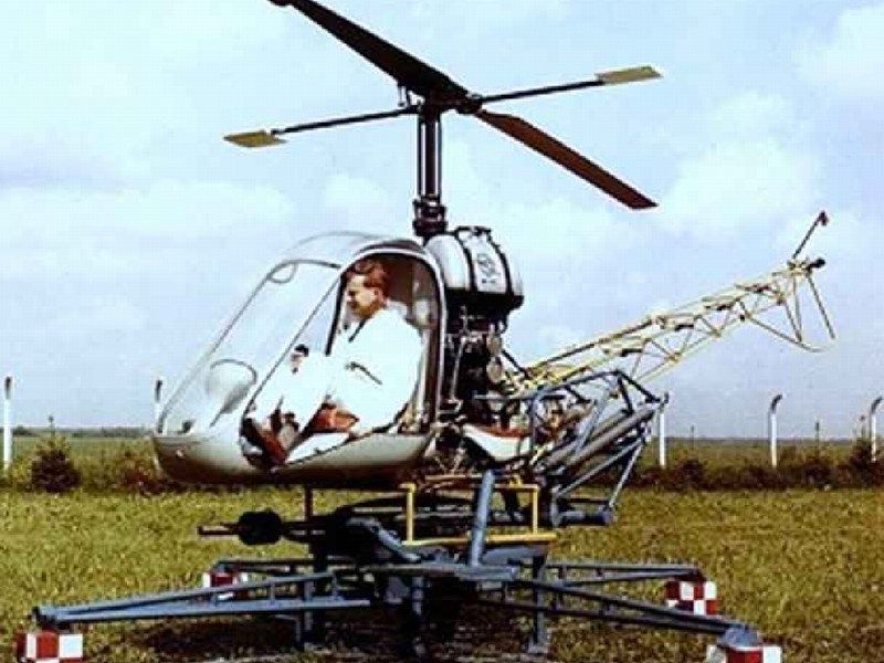
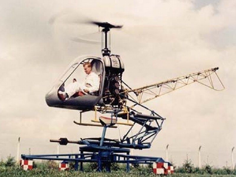
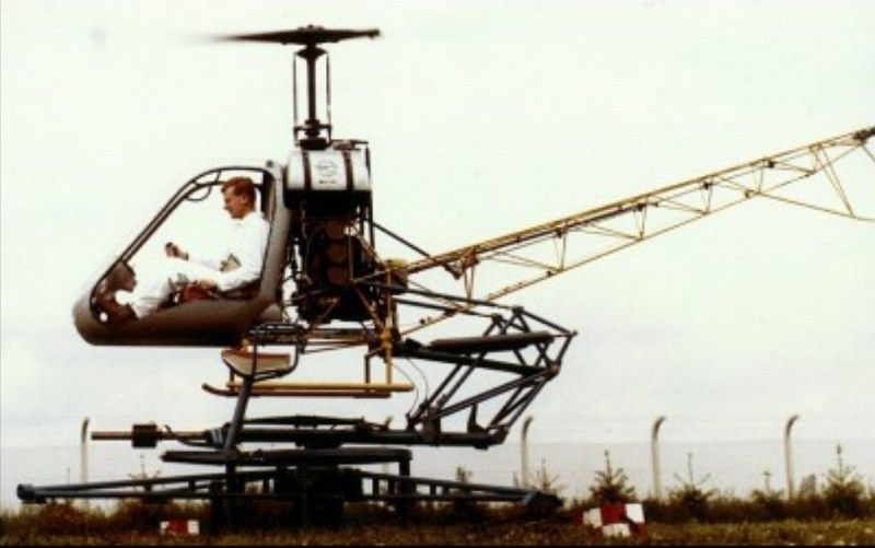
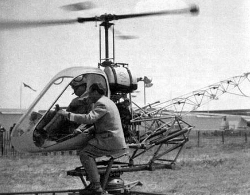
The Bölkow Bö-102 Helitrainer was an unusual ground-based helicopter training aid that was developed and built by Bölkow of Germany in the late 1950ies. It embodied all essential elements of a conventional helicopter, but was mounted on an articulated gantry to allow a student controlled experience of helicopter systems. Designed to be mounted on a swivelling captive rig the Bölkow Bö-102 Helitrainer allowed trainee pilots to practice procedures such as engine starting, rotor engagement and manipulation of the flight controls. Many of the Bö-102's components, including the single bladed fiberglass main rotor were used in the company's next design, the Bölkow Bö-103.
Looks like a kiddie heliride, a toy for big boys huh?
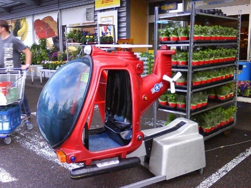
Rolled out in 1957, this Helitrainer was powered by a Hirth 3-cylinder / 2-stroke 40hp ILO L3X375 piston engine rated at 30 kW, driving a simple 21 foot one-bladed fiberglass rotor with a counterweight. In all 18 of these Helitrainers were built operating throughout Europe, training military helicopter pilots. Although unable to fly, they were ideal for the teaching of hovering techniques and were replaced by dual trainer helicopters.
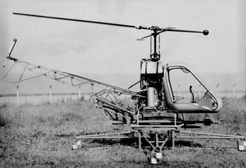
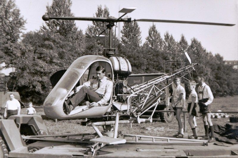
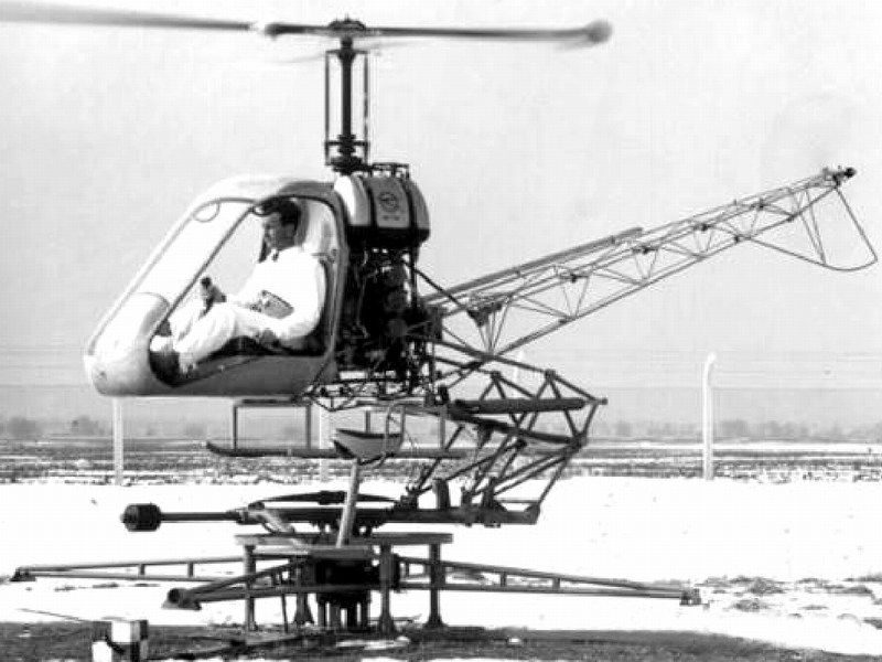
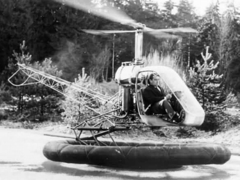
The Bölkow Bö-102 Helitrainer offered a variety of advantages for a safe helicopter training and was developed in land and water based versions, both of which were semi-captive. The first training section was conducted on this model mounted on a boogie. It facilitated the training of starting, tuning the rotary speed, taking off, hovering, turning, and landing. Simple exercising device for beginners’ training. Safety risk minimized by captivation, yet limited flight maneuvers possible. This feature allowed the helicopter to rise to a height of 2m (6ft), turn around a vertical axis and dip at up to 6° but prevented it from flying outside these limits.
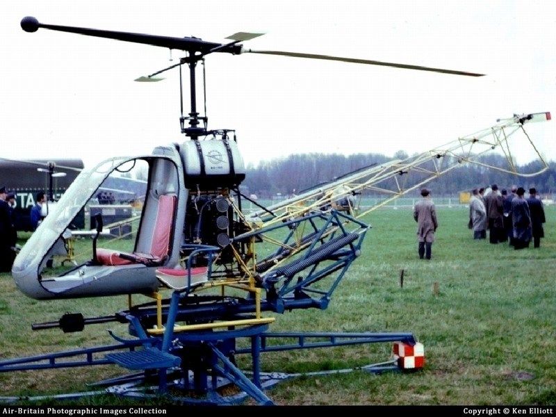
Unfortunately, the Bölkow Bö-102 Helitrainer did not gain general approval because of its costs being nearly as high as a small helicopter. Luckily, very few of them, are still surviving as public display exhibit at the Hubschraubermuseum Bückeburg Germany, the helicopter museum Weston and in Rota museum Spain. Parts of Bö-102B were found at a freight forwarding company in Vlotho and donated to the helicopter museum in Bückeburg. The workshop team, managed to restore few of these experimental helicopter training devices.
Technical data & general characteristics
- Type designation: Bö-102B Helitrainer
- Usage: Single seated captive helicopter trainer for basic helicopter training
- Year of construction: 1958
- Manufacturer: Bölkow Entwicklungen KG
- Country: Germany
- Length: 5.68m
- Main rotor area: 34.8m² (374feet²)
- Main rotor diameter: 6.58 m (21ft 8in)
- Powerplant: 1 x Hirth 3-cylinder / 2-stroke 40hp ILO L3X375 piston engine rated at 30kW
- Power: 40shp
- Gross weight: 770kg (1697lb)
- Take off weight without a platform: 325kg
- Crew: 1 student pilot & 1 trainer (on additional seat)
- Speed: Handcuffed on the ground
- Range: Stationary base coach
-
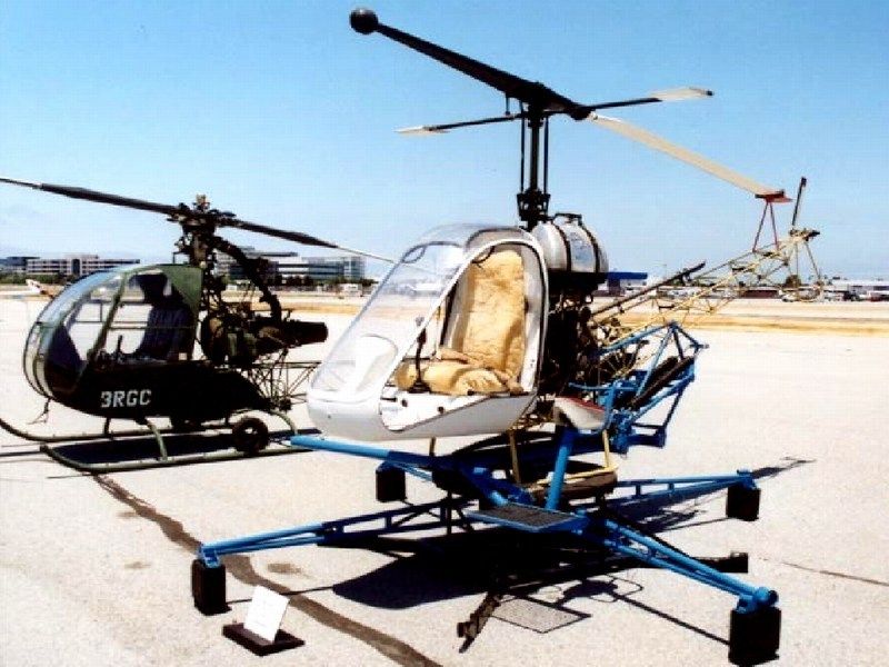
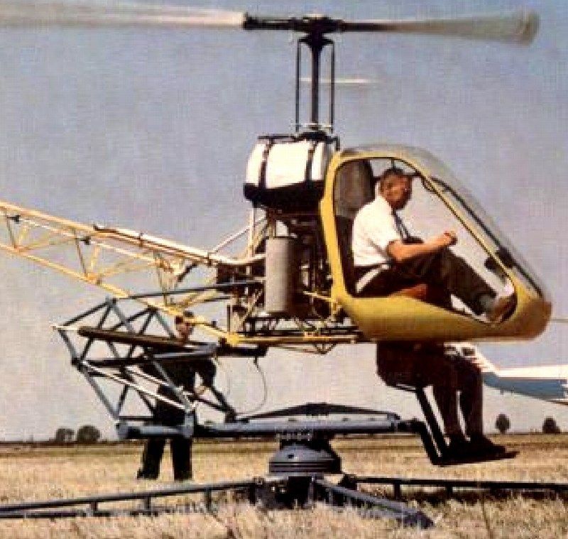
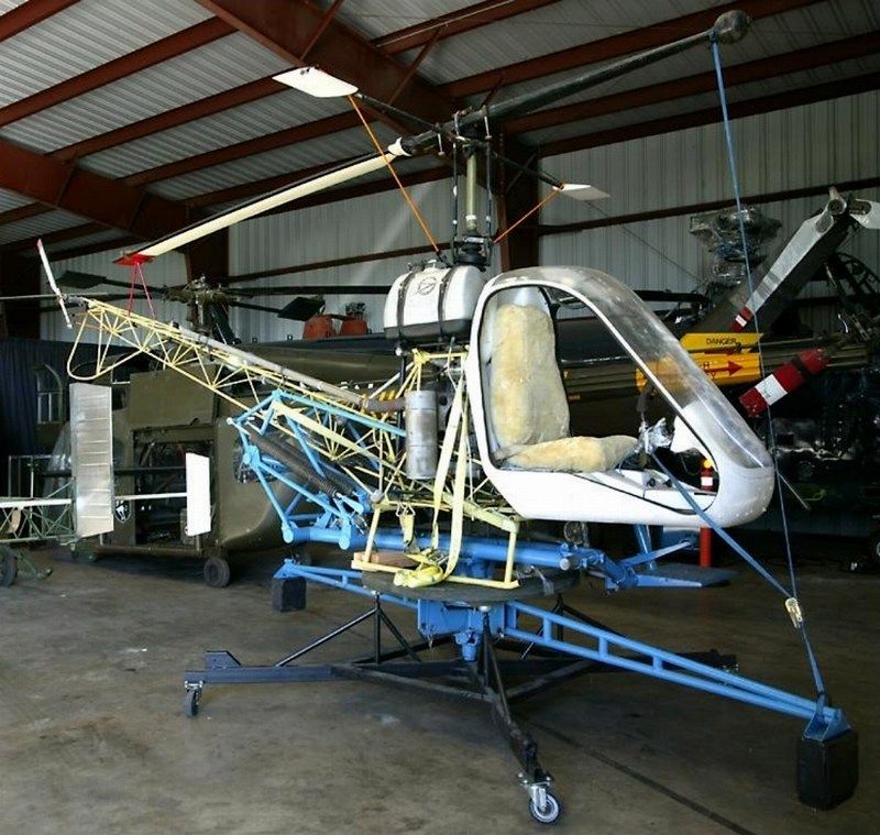
1/18 scale Jukka Tervamäki Engineering JT-9T autogyro scratchbuild
Having tried my (suicidal) virgin 40 minutes flight experience with a friend's homemade autogyro during my summer holidays with him on flight controls and me on the passenger's backseat, I can surely say that you really feel like a bird, sensing even the slightest airwave or gravity accelerating change straight in your floating stomach. As soon as I safely stepped on solid ground again and returned back home in one piece, I felt the iresistable temptation to try a 1/18 scale autogyro scratchbuild. The following article is to describe step by step the 1/18 scale Jukka Tervamäki Engineering JT-9T autogyro, designed by Mr. Jukka Tervamäki and currently flying by ultralight aviators around the world keeping the Mad Max II GyroCaptain's (aka Road Warrior) spirit alive!
In the photo below, Mr. Jukka Tervamäki, with his latest (at that time) creation of the JT-5, which was a predecessor of JT-9, which I'll try to represent in scale.
The basic JT-9 autogyro concept is about a tractor gyro design with good aesthetics and performance with fairly low power. A 1.7 m diameter 2-blades propeller is powered by HKS 700 or Hexadyne Aviation P60 diesel engines, both delivering about of 65 hp at 2400 rpm. The fuselage of the JT-9 is of normal steel tube construction covered with dacron fabric. On the other hand, the JT-9B model is equipped with an electric motor instead of a diesel engine, with only difference the 3-blades propeller and wider front cover to house the battery packs onto both sides of the fuselage. The model I'll try to build in 1/18 scale, is the two-seat trainer (as for the "T") JT-9T model, equiped with diesel engine & 2-blades propeller made by carbon fibers. Having the basic blueprint line diagrams in hand, it was easy to convert them into 1/18 scale with a photocopier and I began the scale model building, starting from zero using 0.25mm styrene card and plastic sprue. To make the construction look more interesting, I decide to build the model in a way that airframe should look like cutaway side opened and let cockpit detail be easily observed.


In the following pictures, the real (one-seat) Alex "GyroBeast2" Lameko's autogyro JT-9, during the successive stages of building.


-
[non-building discussion ON]

Fellow scale modelers, because I am a very new member here, please allow introduce myself. In any case, I wouldn't like the following words to be considered as rudeness or ingratitude, but I would prefer if possible and complies with forum regulations, the fellow modelers answers and responses, be limited to matters relating to the construction methodology or any possible questions or recommendations about techniques have followed until now. My personal belief is that the forums are made for contacting each other and to learn & discuss productively on new techniques that could be useful to our hobby. Believe it or not, I don't like hearing compliment comments - what's the reason after all?. Flattery doesn't make me happy, that's why I never answer to any compliment comments. In no way I would consider myself as a highly skilled craftsman - I am just a moderate level scale modeler with same skills as many other person here. In fact, I'm sure there are much better and more talented scale modelers in this forum, than me. Having under consideration all of the above, I would kindly ask you therefore not to flatter me, because I could possibly get used to it and start behaving like a star - and that, wouldn’t be proper and nice. So, please from now on, do not say "...bravo...", "...congrats..." etc. Please do say "...this is not good...", "...you did it wrong...", "...it does not look nice...", so I could spot the mistakes that might escaped my attention and fix them.
[non-building discussion OFF]
Here on LSM we are Very interested in the future of modelling. Can you tell us what the main important pieces of information in the computerprogram are to successfully get a result Such as yours?
Cees, I'm not really sure that I understand clearly what you asked me, but I suppose that your question is about how I started from scratch, until the final result? Or maybe your question is about how did I start dealing with CAD software proccessing? Please explain again if you please, to let me give the correct answer.
-
CHAPTER V - Applying paint, wash & weather effects
As soon as the Humbrol light grey acrylic primer dried, the model washed with liquid soap and warm water to disappear leaving oil traces, fingertips etc. Usually, there are two available options for a scale modeler, to apply paint on a model:- Paint the individual parts first and assemble the scale model later, or
- Assemble the scale model parts first and paint the overall built model later.
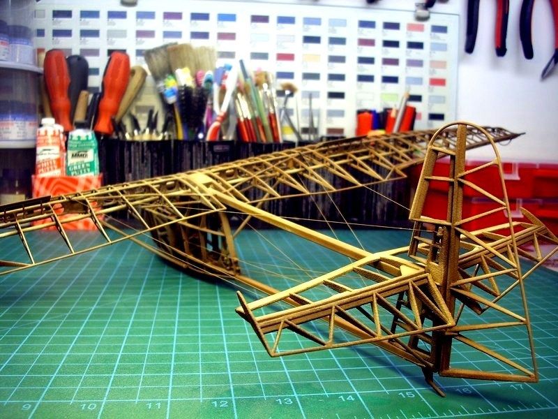
While planing this 1/18 scale IS-A Salamandra model building, the 2nd option seemed as more appropriate and would make my job much easier. A really good reason to stick on this option, is the fact that the Salamadra glider's main frame was entirely constructed of wood. Ofcourse, fabric was covering the wings & tail and plywood was covering the cabin’s nacelle as well. But, since I had in mind to build this model as an artistic "cutaway" view, presented on its wooden frame only, I had no reason to avoid an overall wood colour tones painting.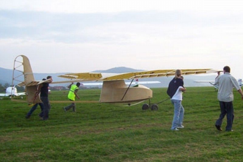
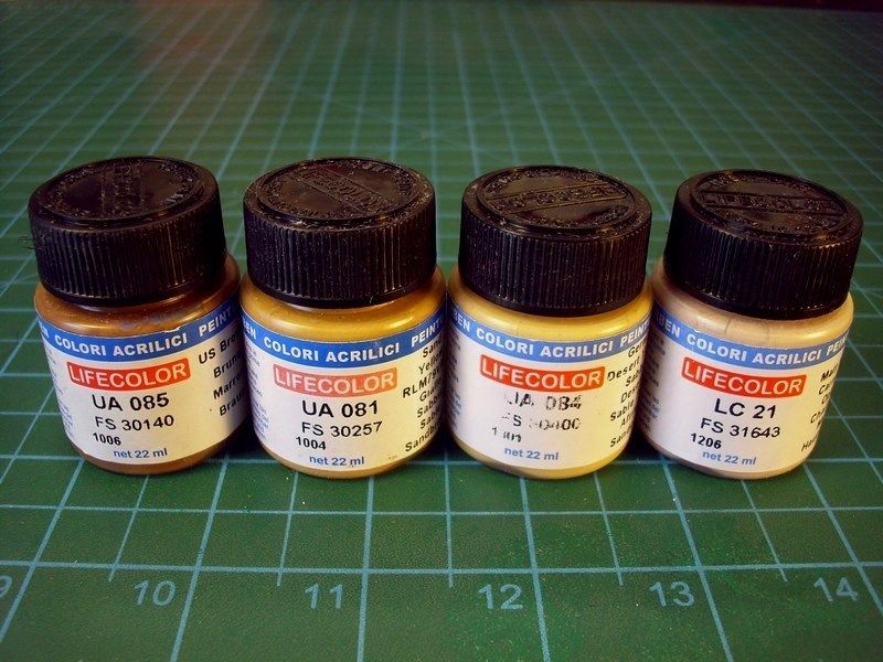
Replicating wood is one of those feared tasks in modeling that many try to avoid at all costs. Having a couple of different methods in mind to simulate wood in scale, but knowing that the following method is much accurate and easier to re-do if something goes wrong, I found good idea to follow some tricks I learned from other builders and changing things that works for me. To simulate the look of rough wood from which was made the glider's frame, I first applied a background colour. I split the areas to be painted in different categories and sprayed four different primary colors on each area. I used the following colors, which seemed to work OK for me, for the basic background. It is important to use an acrylic base colour because it is chemically impervious to the steps that follow.- FS31643 "Matt Flesh Carnicino" available by Life Color as LC21 acrylic,
- FS30400 "German Desert Yellow" available by Life Color as UA084 acrylic,
- FS30257 "Sand Yellow RLM79VAR" available by Life Color as UA081 acrylic and
- FS30140 "US Brown Marrone" available by Life Color as UA085 acrylic.
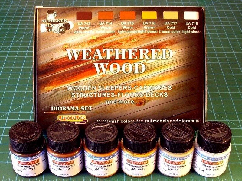
Because the wood composition and quality was not the same everywhere, I also use the Life Color's "Weathered Wood" 6-pack set and repeatedly covered some areas with different shades of very very very diluted & light layers over the previously applied base colours. To do so, I used the following:- Life Color UA717 "Wood Cold light base" acrylic,
- Life Color UA718 "Wood Cold light shade" acrylic,
- Life Color UA715 "Wood Warm light shade" acrylic,
- Life Color UA716 "Wood Warm light shade 2" acrylic,
- Life Color UA714 "Wood Warm light base" acrylic and
- Life Color UA713 "Wood Warm dark shade" acrylic.
I'm not really sure if it is actually vissible into following pictures, but repeatedly applied very diluted & light layers, resulted more natural look of wood shades, without even aplly any oil colours yet. The first applied base colours, are visible under the later applied layers of the "Weathered Wood" shades, setting a base for the next process.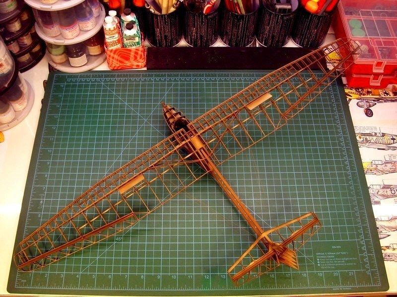
 Studying the available photos I have, whether from my visit to the Polish aviation museum Krakow, Poland or pictures came from individuals who have built IS-A replicas around the World, I noticed that some of the metal parts ie control surfaces rods and cockpit levers, are painted with a green colour, which looks much alike the green that Soviets used to paint their jet fighter cockpits. To be honest, since all the 60 - 70 years old pictures are B&W, I'm not really sure if the actual IS-A gliders had these parts painted green, or if its just a practice by modern replica manufacturers. I decided for artistic reasons only and without being able check this feature authenticity, to paint these levers & rods with mentioned green colour. To do so, I used the FS24115 "Bright Green RLM" available by Life Color as UA055 acrylic and later blend it, to look brighter on middle areas, spraying much diluted FS30257 "Sand Yellow RLM79VAR" available by Life Color as UA081 acrylic, just not to look too dull.
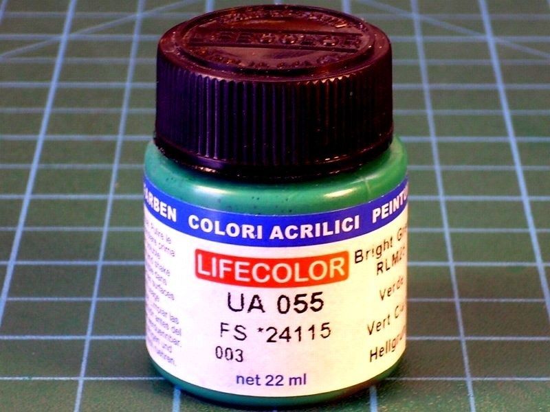
After the green parts painting & lighting, I repeatedly sprayed a very diluted mixture of thinner, Life Color UA717 "Wood Cold light base" acrylic and Life Color UA716 "Wood Warm light shade 2" acrylic at a ratio of 90% - 5% - 5%, over selected areas such as the wings leading edges and a few other points, that should look more enlightened.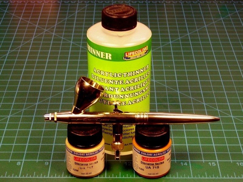
- THE FACT: Nowdays 3D printers are not perfect yet and may leave traces that look like finely ridged surface. Its a result from the resolution of the nozzle laying down the plastic, especially when no acrylic based polymers or V-cured acrylic plastics are used. These special matterials can print fine details, give a smooth & slightly shiny result, but for the moment, cost more.
- THE BAD NEWS: I did the stupidity to use the cheap matterial, in order to keep low the printing cost. And yes, these 3D printer traces, which before painting did not even appear, are now slightly visible.
- THE GOOD NEWS: These printer traces, (am I lucky or not?) look like wood grains! Yeap, that suits me a lot, because what I 'm trying to simulate here, is a glider frame made of unpainted, rough & hard wood. Since other scale modelers try to replicate this exact wood texture effect, I've already have it 3D printed in front of me.
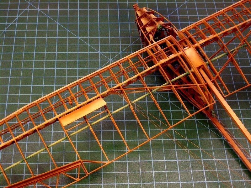
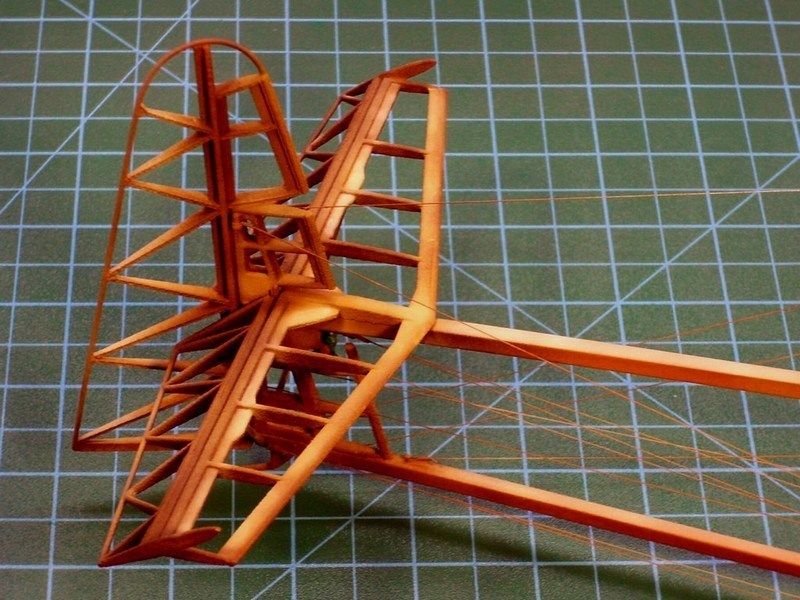
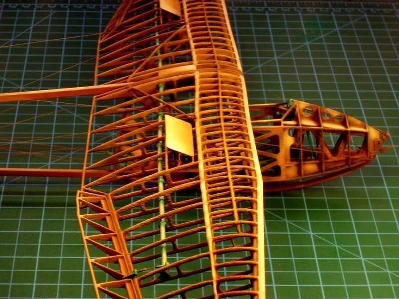
-
1
-
CHAPTER IV - Attempting to join the basic parts
As soon as the individual scale model’s parts were already produced, cleaned & dry fit tested, I had to assemble everything as one piece, without damaging the frame construction. Just because the Salamandra was entirely constructed of wood, I decided that its much better to assemble all model’s parts first, sand if required and later apply paint and weathering effects as a final touch. During assembling process, everything was secured in place & glued with CA liquid adhesive superglue, which found at local market for 0.16 € per tube (each 12-tubes card, costs 2 € only). It does bonds in only few seconds, reaches extremely strength at room temperature and it is suitable for materials such as wood, rubber, plastic, metal, ceramics, leather, marble, polyethylene, polypropylene, teflon etc. Once I´ve tried this CA superglue on my scale models, I’ve never go back.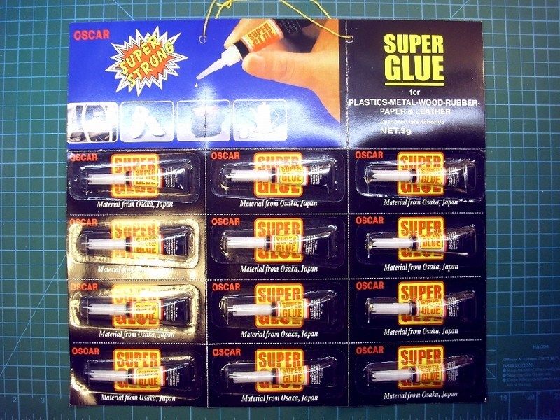
Following the 1/18 scale printed diagrams and using a new sharp Nr 11 stainless steel surgical blade and 4x4 mm sectioned styrene rod, it only took about 2 minutes to prepare the basic tail boom frame. The supporting frame consists of two 228 mm long beams that join the front compartment (cabin & wings), with rear part (tail elevator & stabilizer fins).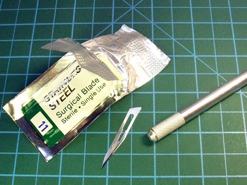
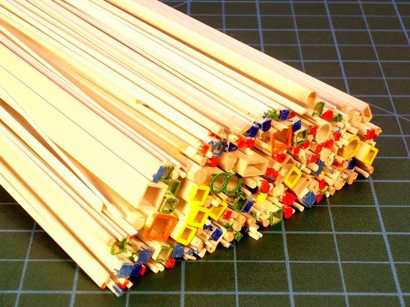
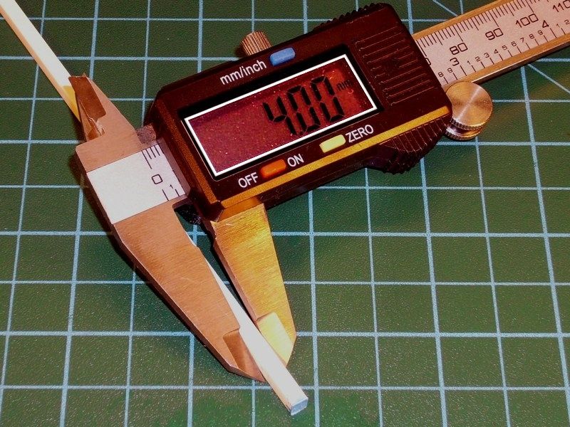
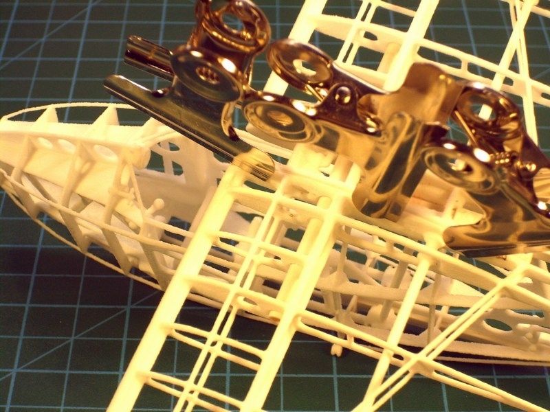
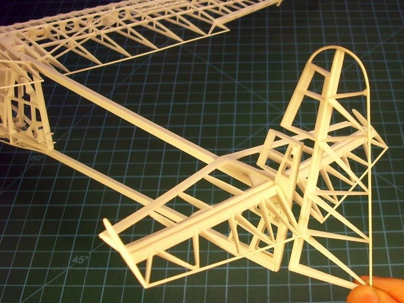
The only piece that remained without gluing, is the tail rudder fin which will be set in place after paint. The glider model’s wingspan is now fully developed and looking really big as it is spreading lazily all over my working bench - approx 70 cm from one wingtip to the other.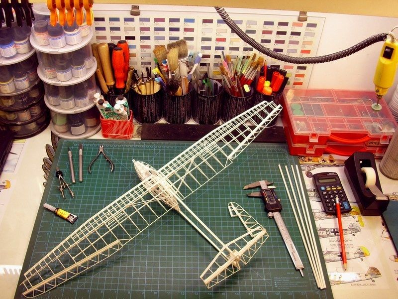
Some tiny gaps between the parts connections, were filled with putty, applied with an old brush. As soon as the joints between the cabin, wings & tail boom parts were securely glued with CA superglue and later filled with putty on tiny gaps, it was carefully sanded with nail files & sanding sponge block, found at the local beauty care shop - the only good moment when following wife on her shopping. They are cheaper than dirt, since each nail file cost € 0.1 (each 10-nail files card, costs € 1 only) and the sanding sponge cost € 0.5 per block.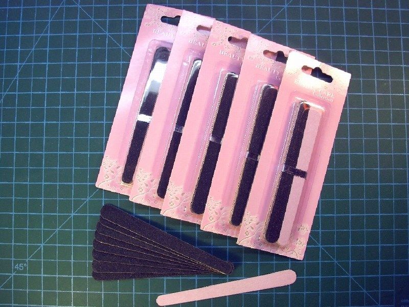
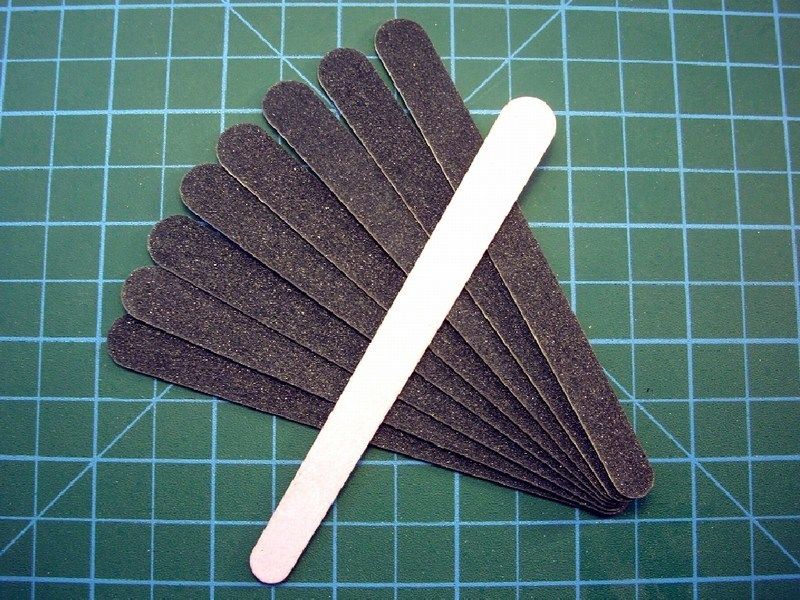
When it looked OK to me, the whole model was sprayed over with Humbrol acrylic primer to spot any mistakes and placed into a box to wait the final paint applying.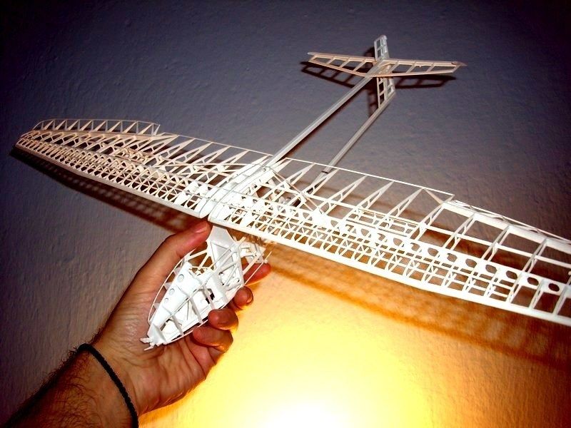
-
1
-

1/18 scale Tervamaki Engineering JT-9T autogyro scratchbuild model
in LSM 1/35 and Larger Work In Progress
Posted
It’s been few months since the JT-9T project was complete. I found nice idea to place it on a display base, simulating an airfield area with concrete ground. The idea was to establish an idea of an abandoned small airfield, now used by general aviation pilots for their weekend excursions. From my local store, I bought a 20x30cm polished wooden picture frame.
I add some grams of plaster powder and few drops of water with a syringe into a soft rubber cup to make the right mixture. Materials like plaster, start as a dry powder that is mixed with water to form a paste which liberates heat and then hardens. Unlike mortar and cement, plaster remains quite soft after drying and this characteristic make plaster suitable for the job. Keep in mind that adding salt into wet plaster mixture, reduce the plaster's hardening time and adding vinegar into wet plaster mixture, extend the plaster's hardening time. When the first layer of thinned plaster applied on the picture frame, a glass were pushed against the plaster to form a flat basic strong cast. The basic idea, is to produce a totally flat cast and later add some detail or apply extra stuff where is needed.
I left it few hours to get harden in order to be sure that the cast wouldn't break when I would try to cut it into desired shape. Meanwhile, I took the soft rubber cup which I used to make the plaster mixture, squized it to break the last hardened plaster left inside, so it would be easier for me to clean it afterwards and prepare it for any future mix. That's the reason this soft rubber cup were used for.
As soon as the plaster cast got harden, cut into shape and the concrete plaques were lined with a scriber, I used my airbrush to paint it. After the polished wooden frame was covered with masking tape, three different acrylic paint layers were applied on the plaster surface. First, mat black colour covered the area and then a light grey applied with airbrush, spraying in almost zero degree angle, to let the darker areas between the concrete plaques remain naturally dark. The corner was paint with earth tones and as soon as the acrylic colours dried, I tried some drybrushing on selected spots using sand tones.
As for he grass & plants, I used three different ways:
Water based white glue for wood, which becomes transparent when it dries, is just the right for the job. So, I opened a 500 grams canister bought for 2€ only, pick a small quantity, add just few drops of water with a syringe into a small metal container to make the right mixture and finally I applied on the desired areas to be filled with grass & plants, using a wet brush. Because the mixture is enriched with water based glue, it is easy to correct possible mistakes.
I also tried some camera shots with black paper background (instead of white) & different light conditions and I was surprised on how the model looks like. From now on, black background and low level lighting only...
PS. A little sparrow bird is now present on tail fin