Umlaufmotor Posted January 29, 2014 Posted January 29, 2014 Yeah, I know - the WNW Albatros D.V Ltn. Adam is not finished yet, the Hansa Brandenburg W.29 also not yet and the Mercedes D.IIIa - engine must also wait. I'm also still busy with the Fokker V.4 http://forum.largescalemodeller.com/topic/566-fokker-dreidecker/ - but I have no desire to continue building this little Dreidekker. Well, so I do not get bored, I started with the WNW Fokker EI.The EI 5/15 by Kurt Wintgens with the high-mounted wing.This thing will be a strictly OOB built .............. no super detailling and no-frills or so............... Ahh - stop - I will use the Taurus Oberursel U-0 Umlaufmotor and HGW-Seatbelts First I started with the cockpit.Here, all four turnbuckles were removed for the hanger bracket to the rudder pedals. Brass turnbuckles will be mounted later at this point. Servus Bertl 1
Umlaufmotor Posted January 29, 2014 Author Posted January 29, 2014 Then the engine cowling.The attachment points were less well represented by WNW. This Cowling was kept and screwed in the original with two steel cables. I also wanted to represent these Details on my E.I.First, the cowl was abraded with sandpaper, and thereafter attached the two recesses for the tensioning cables. Next, the Cowling was heavily and veeeeery careful thinned with an Dremel. How thin?Well, you see here a pair of tweezers with the imprint "rust-free" at the end of the tweezers......................... .................. you can see this print almost through the plastic. Servus Bertl
Umlaufmotor Posted January 29, 2014 Author Posted January 29, 2014 The two side panels have also been thinned down at the edges.These edges were slightly bent wavy to leave a used impression. Servus Bertl
Ssasho0 Posted January 29, 2014 Posted January 29, 2014 Hi Bertl, I will be watching this build for tips and tricks (as usually). I was thinking that you will have to thin the cowl and then, voila, you thin it to "see thru" dimensions Good luck and try to keep to the OOB plan Best regards, Sasho 1
JonathanReed Posted January 29, 2014 Posted January 29, 2014 Ohh man! Thats nice. Glad you arent detailing it too much! 1
Umlaufmotor Posted January 29, 2014 Author Posted January 29, 2014 Well, I love my Dremel ........................ The top cover was also milled thinner in the fuel gauge, the filler neck, and the MG mount. This gives the impression that these parts are realy made of thin aluminum.The two fuel caps were also removed. Servus Bertl
Umlaufmotor Posted January 29, 2014 Author Posted January 29, 2014 The abraded rivets on the Cowling were presented with thin hot-drawn plastic rod. With fine steel wool, the "selv-made plastic rivets" were ground until only small elevations are visible. Servus Bertl
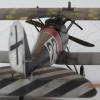
Umlaufmotor Posted January 29, 2014 Author Posted January 29, 2014 Here can be seen the Front cowling and the top cover . The MG-control mechanism may not work as it was presented in the model. The Front cowling could not be removed in the original, without degrading the MG mechanism.That would make no sense.I'll change it later. I hope it still exist good Images to be able to recreate this correct............................... The "Fokker-screws" (red circle) were also drilled out. Servus Bertl
Umlaufmotor Posted January 29, 2014 Author Posted January 29, 2014 Here are just creating new turnbuckles made of brass. Servus Bertl
Umlaufmotor Posted January 29, 2014 Author Posted January 29, 2014 A new tension roller ( is this the correct word?? ) is "under construction" and made from plastic waste . so, that's all for today Servus Bertl
The Red Baron Posted January 30, 2014 Posted January 30, 2014 Inspirational stuff as always, Bertl - tell us, how are you going to achieve the swirly cowl finish?
Ssasho0 Posted January 30, 2014 Posted January 30, 2014 Hi Bertl, I have a question also - how do you made the cut on the bellow picture? Do you used the resin saw or some other tool? It doesn't look like made with a scalpel! Best regards,Sasho
Administrators JayDee Posted January 30, 2014 Administrators Posted January 30, 2014 This is just amazing. This is sure one to follow. How did you add those recesses at the rear of the cowl?
Umlaufmotor Posted January 30, 2014 Author Posted January 30, 2014 @Red Baron:I still have no idea how I'm going to represent these swirls. I think I'm going to try different things, but I will present the result and show what technique I used.@Guy5Y: Thank you, Guy. @Ssasho0: Sasho, yes, I used a Resinsaw. This saw allows very thin and straight saw cuts.@James H:I used a "Höhenanreißer" for those recesses. Unfortunately, I don't know the English word for it, but I think these pictures explain how I did it. Servus Bertl 1
Administrators Fran Posted January 30, 2014 Administrators Posted January 30, 2014 Another masterpiece!!!! Once again fantastic tips!!
mspaw Posted January 31, 2014 Posted January 31, 2014 Its a machinists height gauge. Really quite useful for marking cut lines and the like besides its original purpose of measuring. Ive used one many a time but never to create a scribe in plastic. nicely done! Are you still milling some of your engine parts now and then? -Michael
Umlaufmotor Posted February 3, 2014 Author Posted February 3, 2014 Which of my engine parts you mean, Michael? Servus Bertl
mspaw Posted February 5, 2014 Posted February 5, 2014 Bertl- "Are you still milling some of your engine parts now and then?" Sorry that question came out of nowhere. Back in the day on the Aredrome forume you were pointing out some of the parts you were milling for your Mercedes D.IIIa. http://www.theaerodrome.com/forum/models/47714-again-wnw-albatros-d-v-12.html I had asked for a set back then but life intervied and I never got a chance to pick them up from you. I now have a cnc mill and am wondering if you would be willing to share youre cad file so I might make a set form myself. Im also wondering if you have milled many other parts for your builds. All the best! -Michael
Umlaufmotor Posted February 5, 2014 Author Posted February 5, 2014 Oh, you mean these parts, Michael ..................................................... long long time ago. I think I still have some of these parts. The CAD drawings no longer exist, due to a defective hard drive, all my AutoCAD- and Milling -files were lost. It's been just about 3 months. Servus Bertl
chuckt5 Posted February 12, 2014 Posted February 12, 2014 Hello Bertl. Great see your work again! I was wondering what tool bit you find works best with your Dremel when thinning out plastic panels?
Umlaufmotor Posted February 16, 2014 Author Posted February 16, 2014 Hi chuckt5, I used allways this tool bits for my dremel, when I'm thinning out the engin-cowl ore other plastic parts. Servus Bertl
Umlaufmotor Posted February 16, 2014 Author Posted February 16, 2014 ..................and here two small updates for today. First, the test for the fastening ropes on the cowl. This is a 0,12mm fishingline, painted with a mix of 80% Alu and 20% NATO-black. For final mounting, I think I will use a 0.8 mm fishing line. Servus Bertl
Umlaufmotor Posted February 16, 2014 Author Posted February 16, 2014 And here is the second small - a really small - update.The kit part # 35, the pulsator........................made it a little bit more "real". First, the original ....................... ...................................and here is 32 times smaller. Servus Bertl 3

Recommended Posts
Create an account or sign in to comment
You need to be a member in order to leave a comment
Create an account
Sign up for a new account in our community. It's easy!
Register a new accountSign in
Already have an account? Sign in here.
Sign In Now