

JayDee
-
Posts
3,273 -
Joined
-
Last visited
Content Type
Profiles
Forums
Events
Gallery
Posts posted by JayDee
-
-
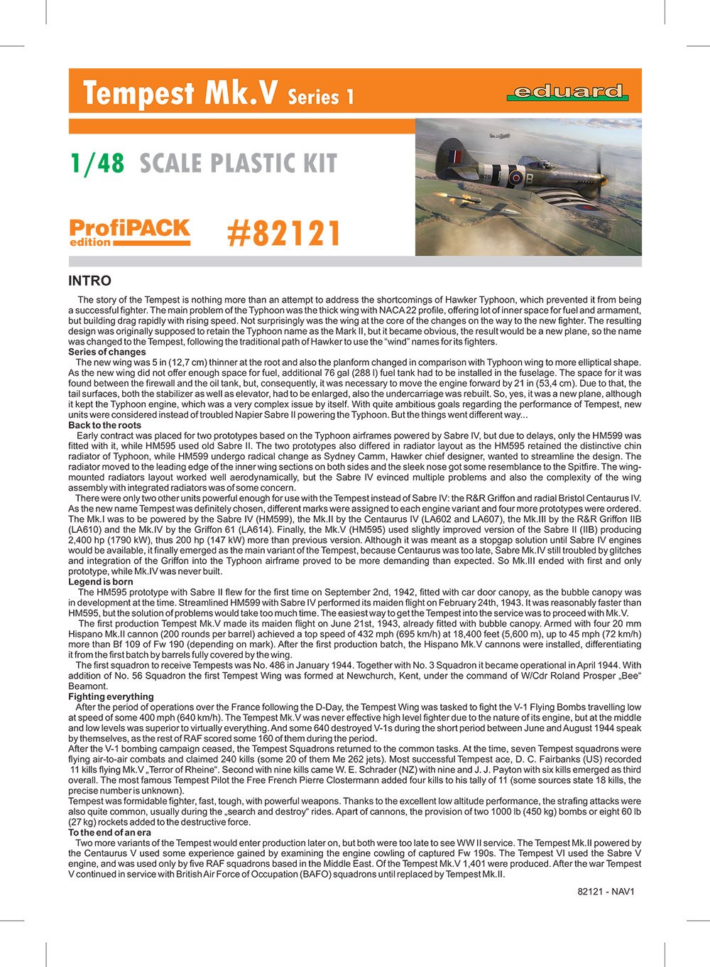
1:48 Tempest Mk.V Series 1
Eduard
Catalogue # 82121
Available SOON from Eduard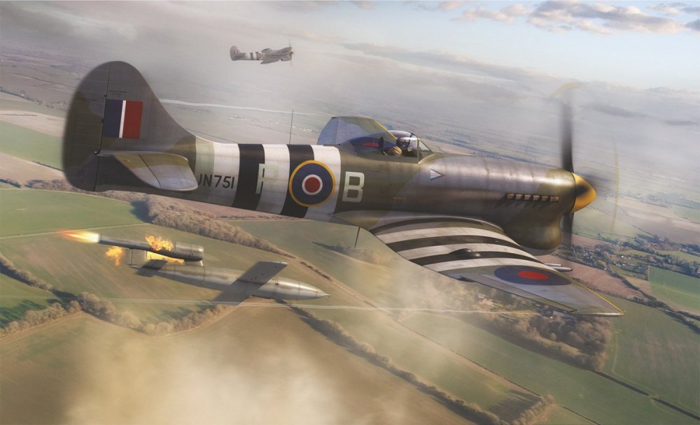
In March of 1940, Hawker initiated a number of design studies aimed at improving the Typhoon. Among these studies were ways of improving the Typhoon's high-altitude performance. These involved the use of a new wing design that featured a thinner wing section and a reduced wing area. The new wing had an elliptical planform and showed a great potential for increasing performance at altitude while reducing the tendency of the original Typhoon wing to buffet at speeds around 500 mph. The maximum depth of the new wing occurred further back, at 37,5 % chord, while the thickness/chord ratio reduced to 14,5 % at the root tapering to 10 % at the tip. This meant that the new wing was five inches thinner at the root than the original Typhoon wing. The thin wing meant that alternative space for fuel had to be found and this was achieved by moving the engine 21 inches forward and inserting a 76-gallon tank between the firewall and the oil tank. The redesign also included a new undercarriage and the latest of the Sabre engine, the Mark IV.
In order to save development time, Sidney Camm decided to mate the new wing to a modified Typhoon airframe which retained the Sabre powerplant. The RAF ordered two prototypes under Specification F.10/41 18 November of 1941 and the project quickly became known as the Typhoon II. Hawker´s biggest problem with the new fighter was the engine. Upon entering service in 1944, the Tempest was used as a low-level interceptor, particularly against the V-1 flying bomb threat, and as a ground attack platform, in which it supported major events such as Operation Market Garden. Later, it successfully targeted the rail infrastructure in Germany and Luftwaffe aircraft on the ground, as well as countering such attacks by German fighters. The Tempest was effective in the low-level interception role, including against newly developed jet-propelled aircraft such as the Messerschmitt Me 262. The further-developed Tempest Mk.II did not enter service until after the end of hostilities.
Extract courtesy of Wikipedia and hawkertempest.seThe kit
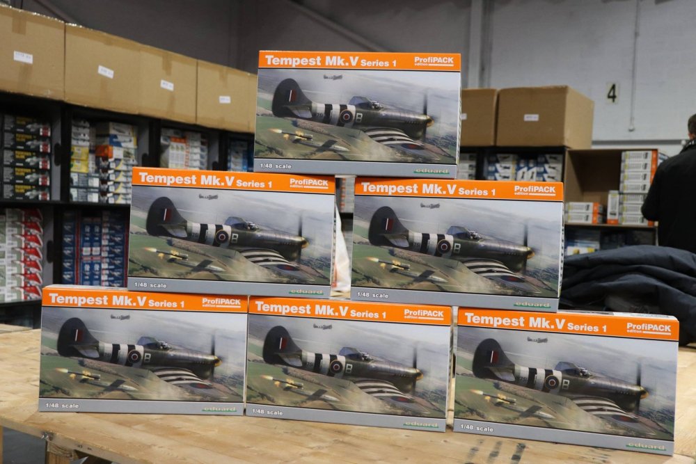
It was certainly a last minute rush for Eduard to prepare their new-tool Tempest Mk.V in readiness for limited sales at Scale Model World, Telford, this year. An announce was made on social media, informing of a limited number of kits (200 pcs) that would be available for sale over that weekend. Along with the kits, Eduard would also offer the first sets of their own aftermarket for it too. When the show opened, the queue to pick these up was long! My sample was ready to pick up at the show later that day, so as this is a brand-new release (no relation to any previous kit), I thought I’d tend to a review straight away.
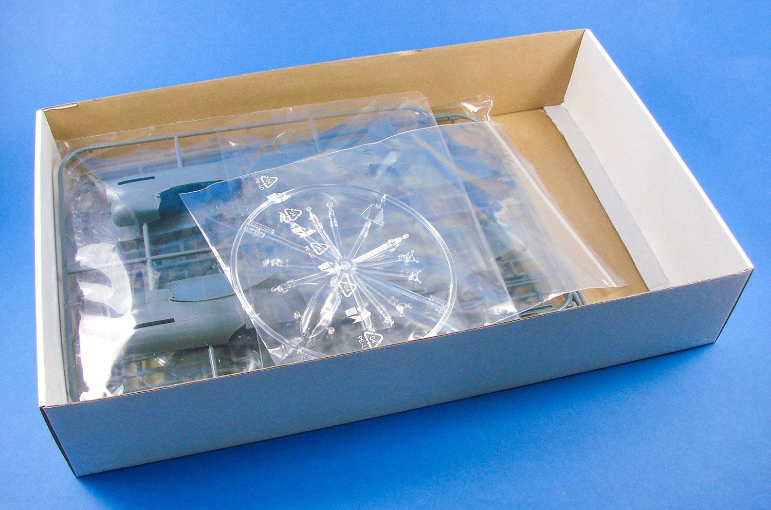
This kit is a ProfiPACK edition, and a full-release version, including both photo-etch and masks. The kit itself is packed into the size of box that we’ve seen with many of their 1:48 fighter releases, with a superb image of Wing Commander Roland Beamont’s Tempest having just tipped a V-1 flying bomb off target. Of course, Beamont’s machine would haveto be included with a release such as this, with him being synonymous with the type and his actions in destroying the vengeance weapons. Inside, there are four medium grey styrene sprues, with the fuselage sprue being packed separately to the other five which share the same resealable sleeve. A circular, clear sprue is supplied in a zip-lock bag. Underneath the plastic lies a colour-printed PE fret in a small sleeve, plus a set of masks. To complete the contents, a 20-page A4 manual is included.
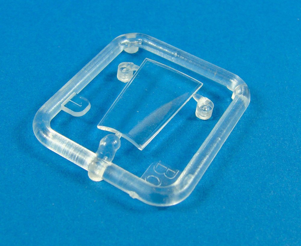
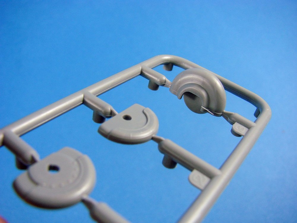
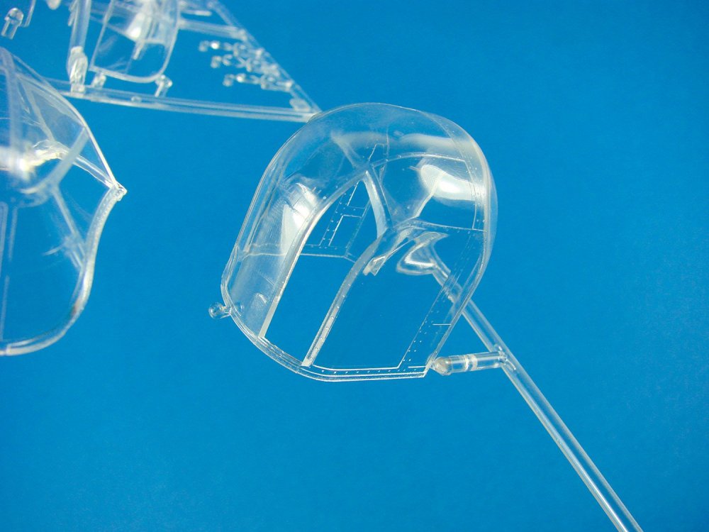
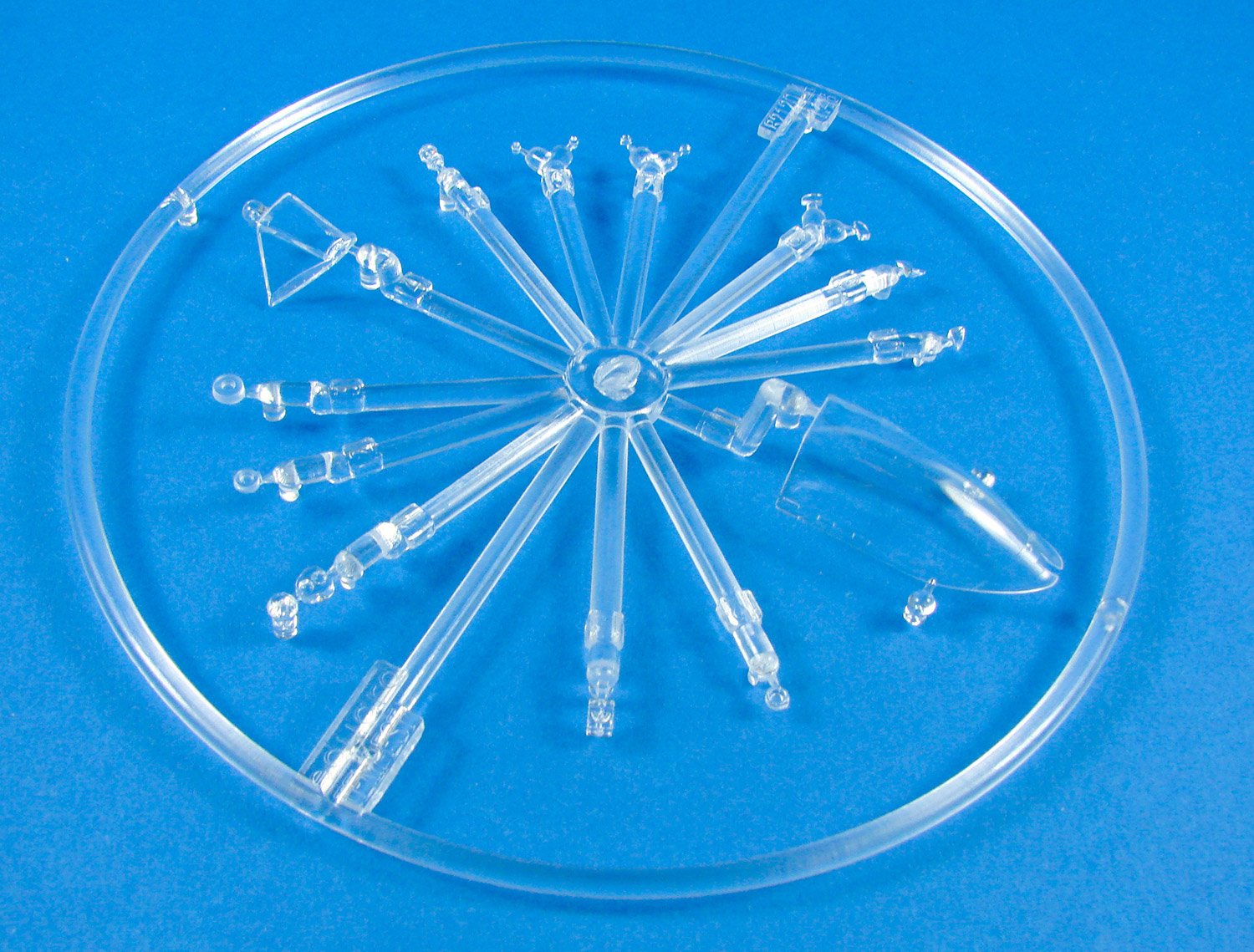
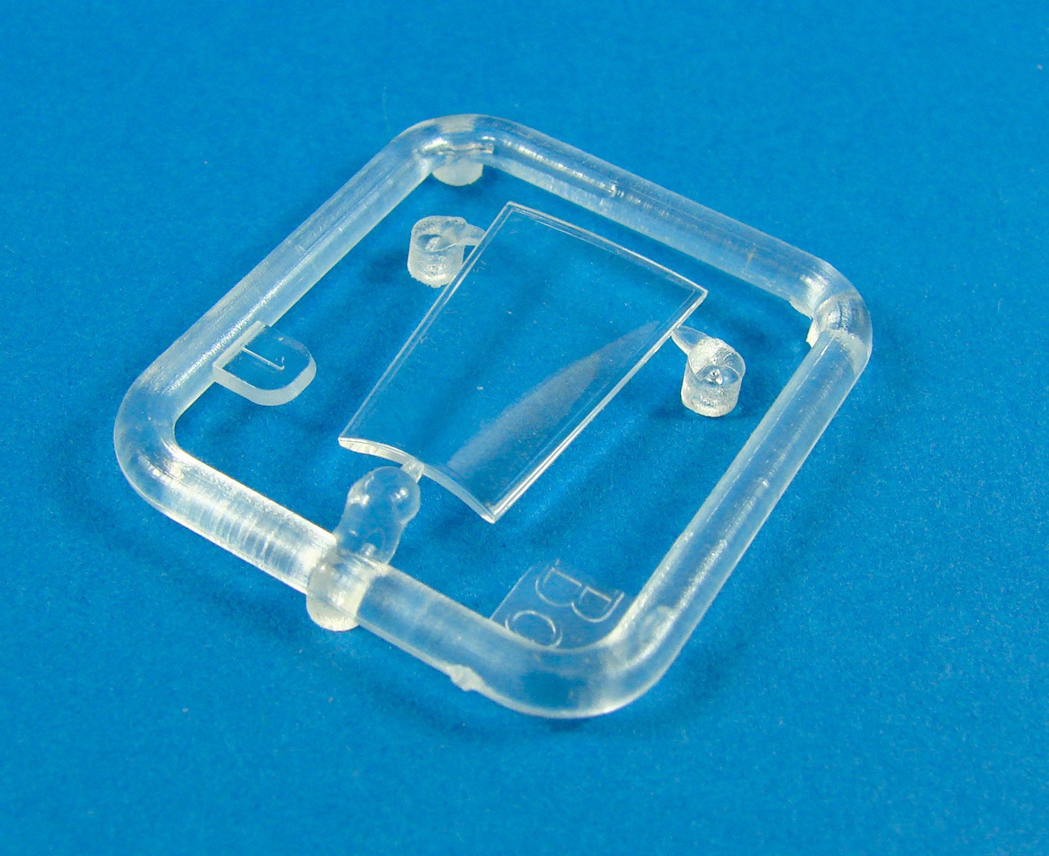
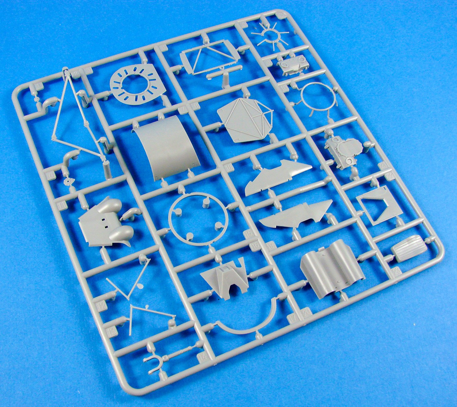
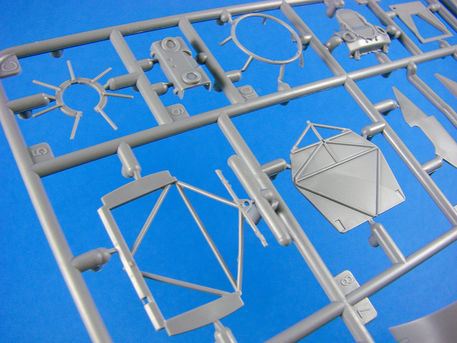
Sprue A

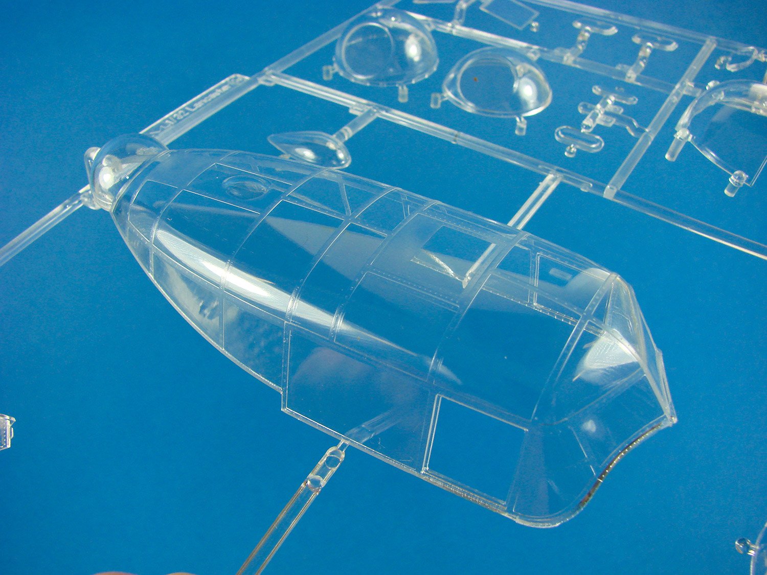
We start with the clear sprue, and as with a lot of Eduard’s releases over the years, this one is produced as a quirky, circular shape, moulded with crystal clear clarity. Here you will (obviously) find the windscreen with integral fuselage fairing, and the rear, sliding hood. Another fourteen parts occupy this sprue, of which thirteen are slated for use. These parts include the compass, rear fuselage lights, wingtip light, cockpit lights, gun sight, and lower wing lights.
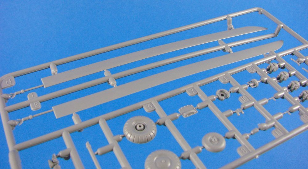
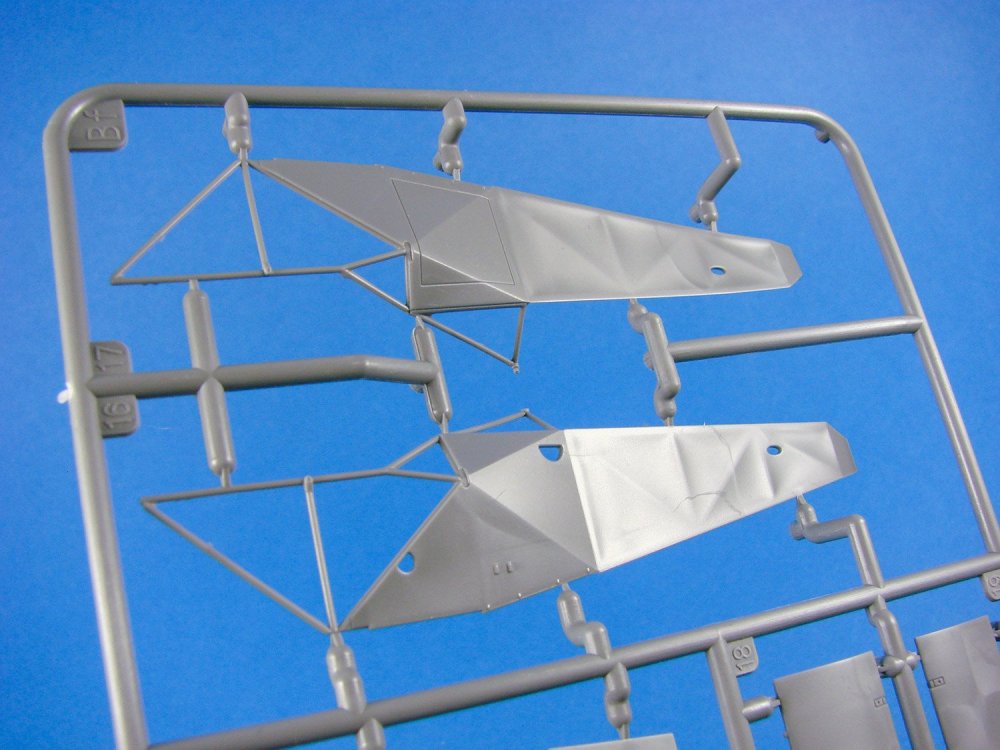
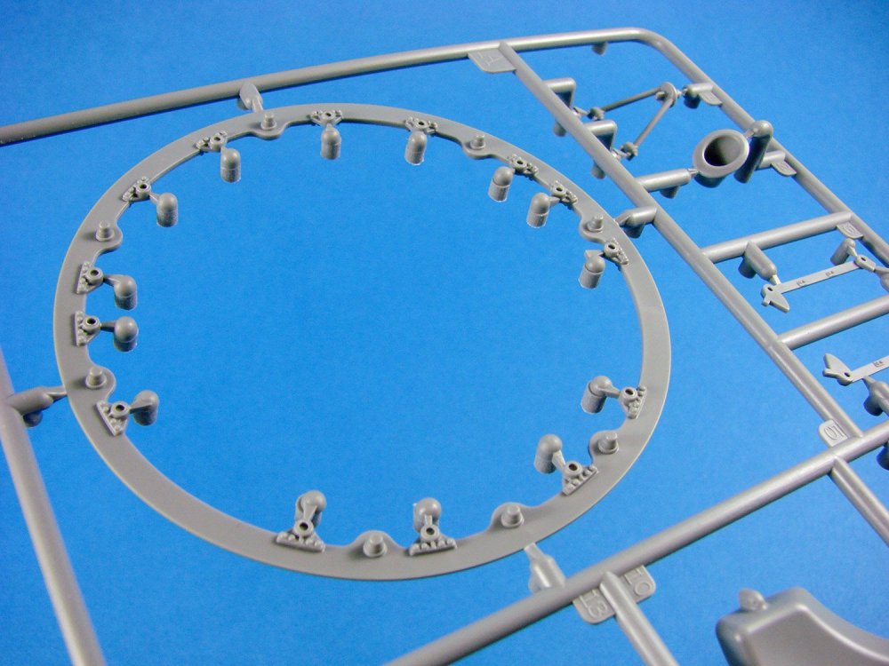
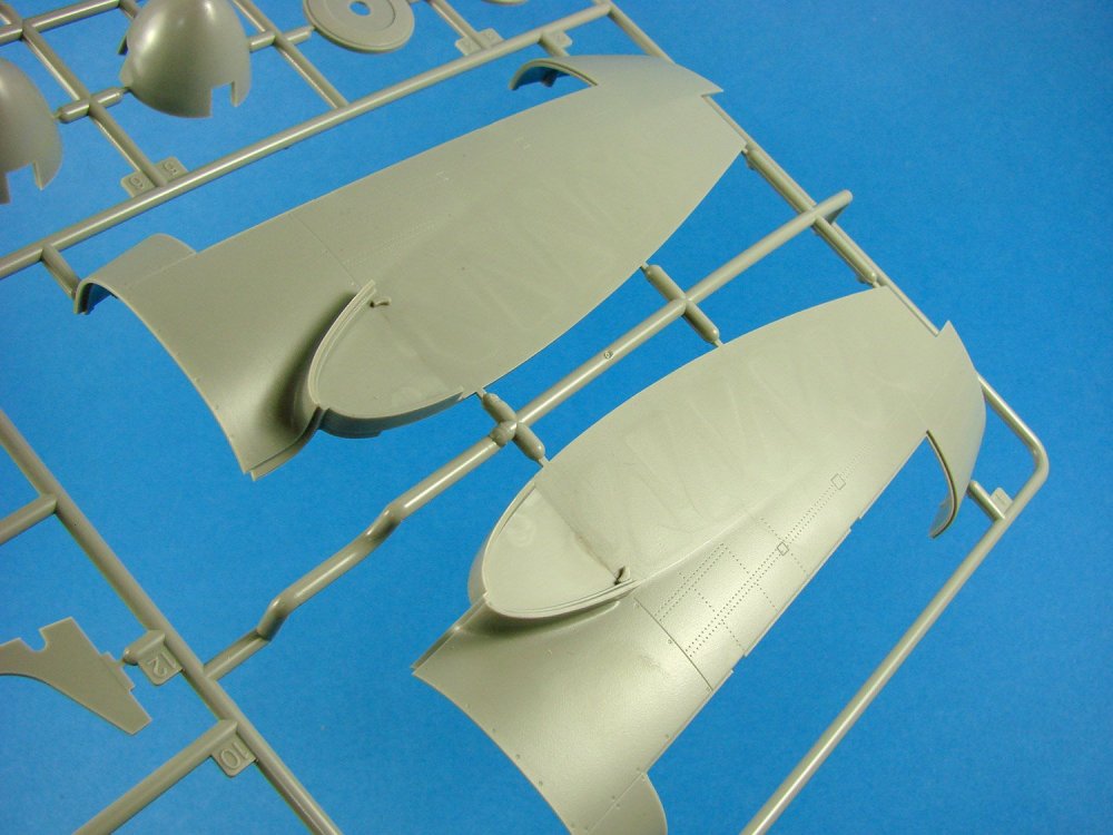
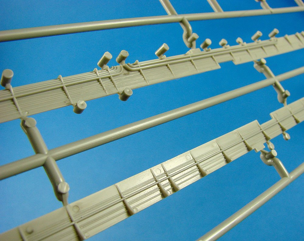
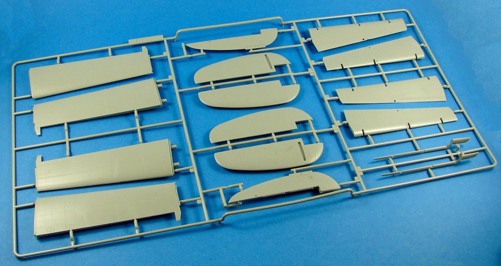
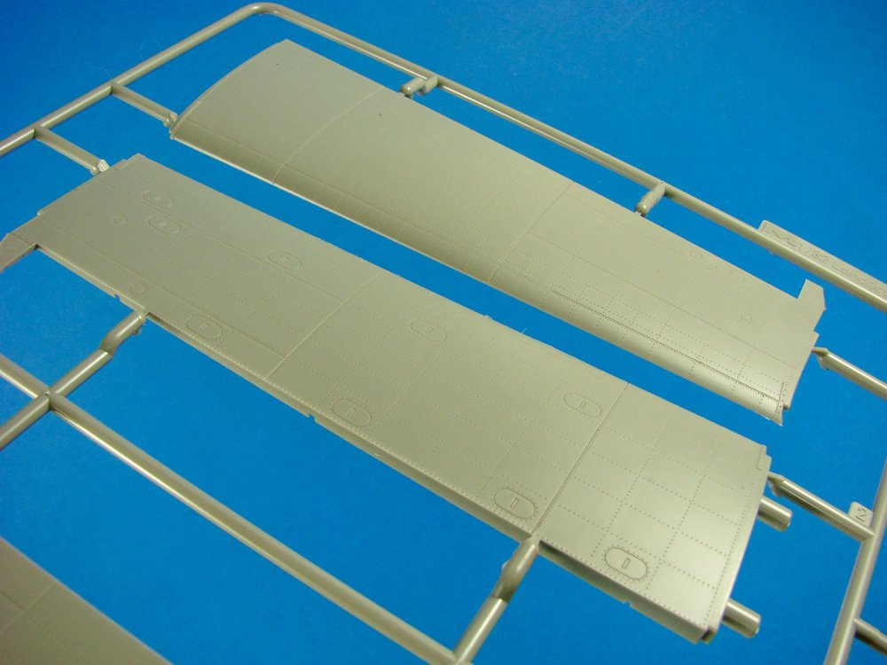
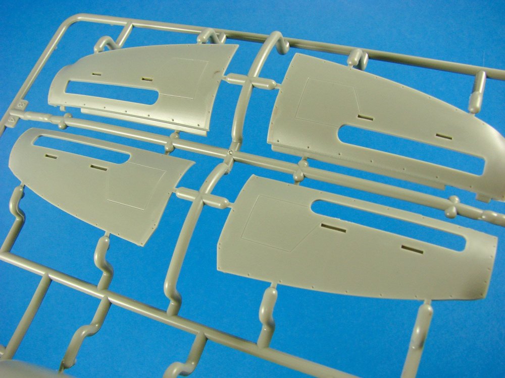
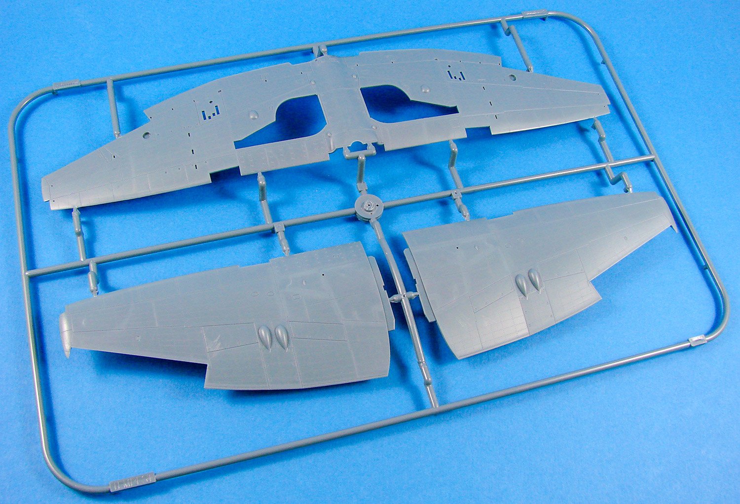
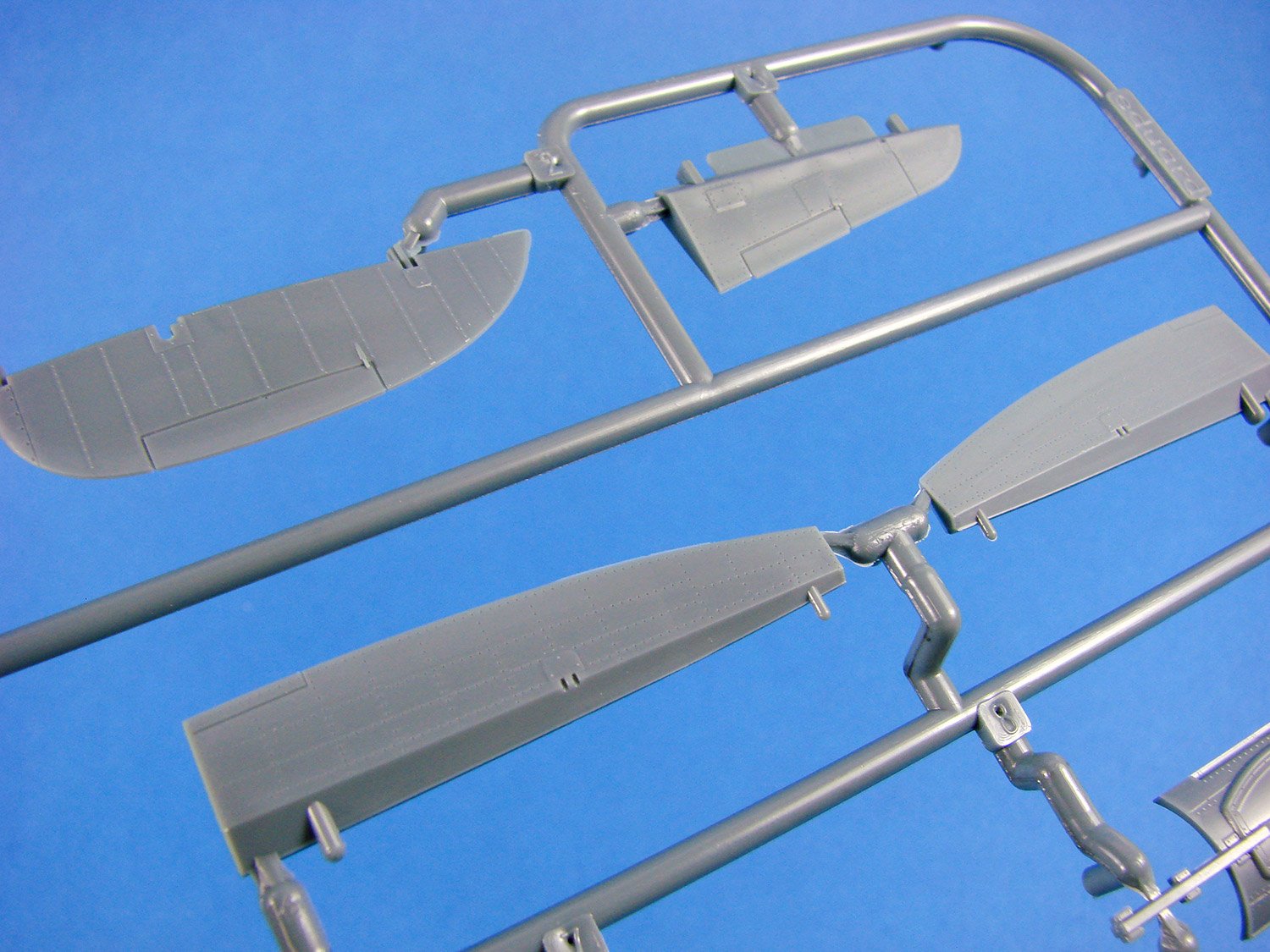
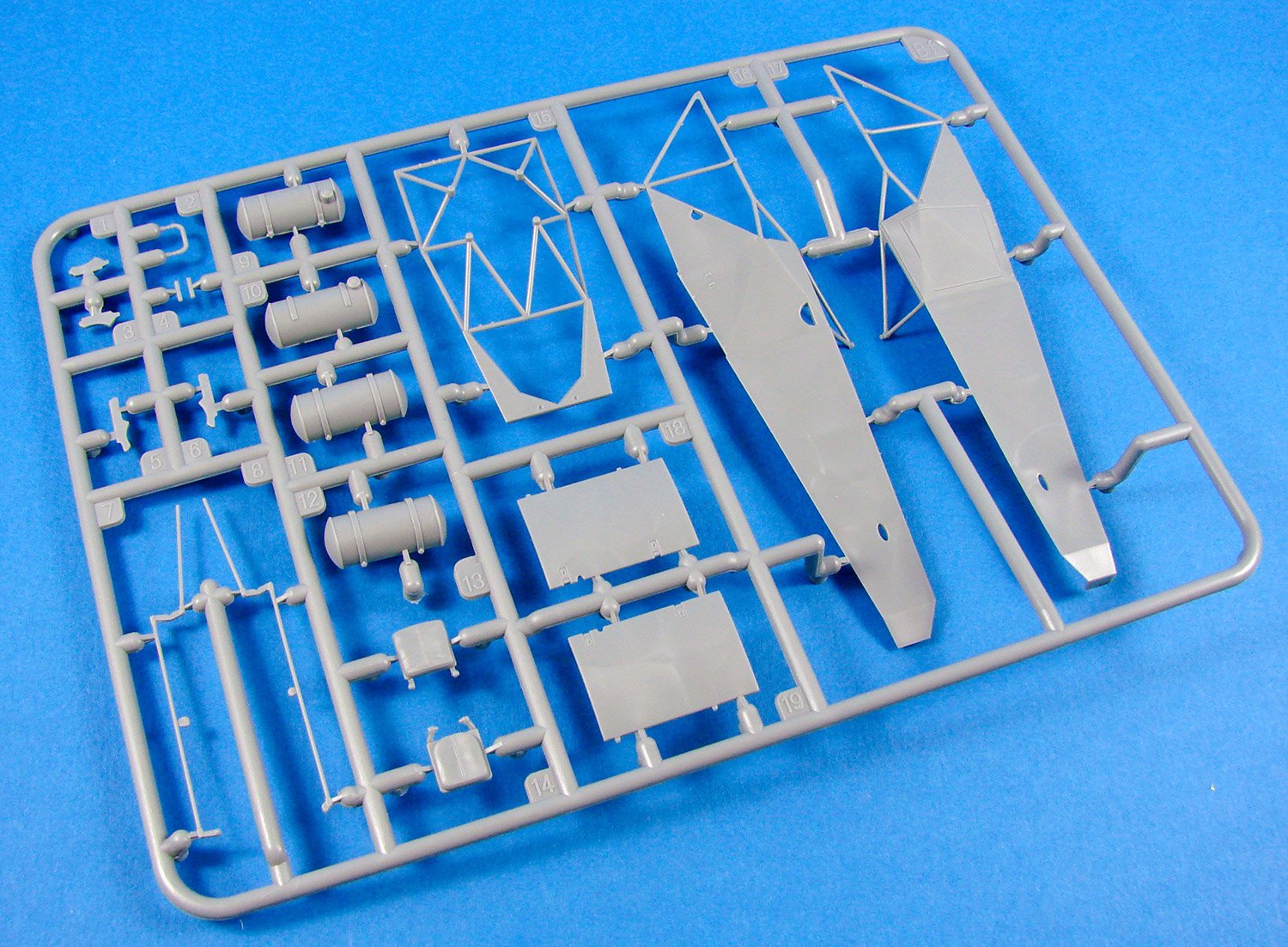
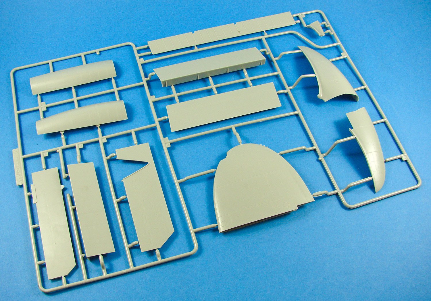
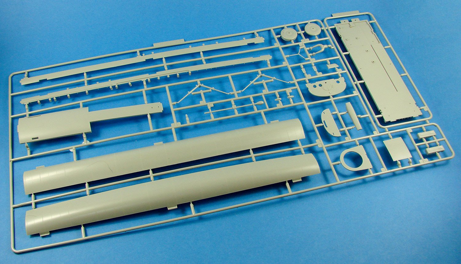
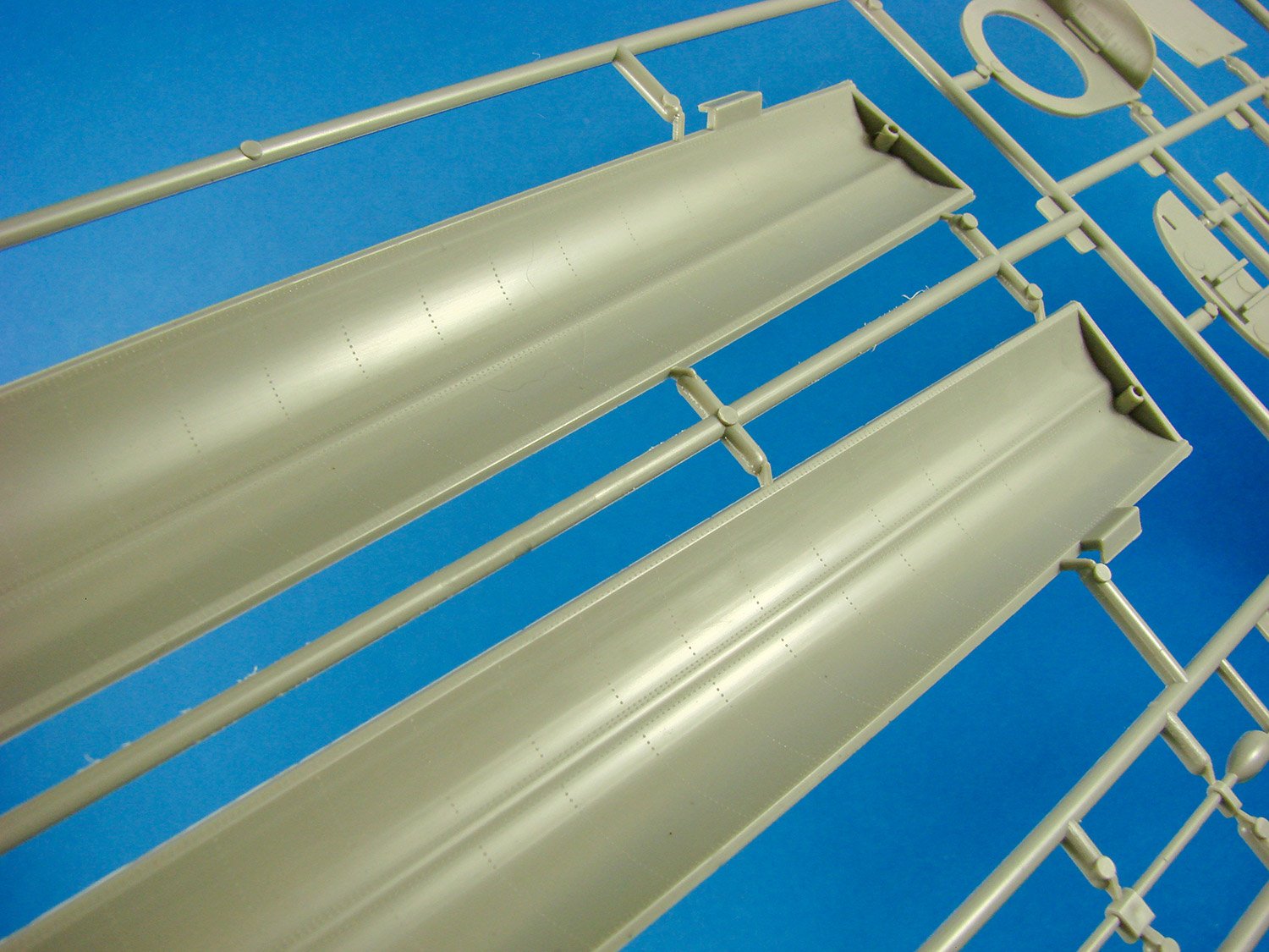
Sprue B

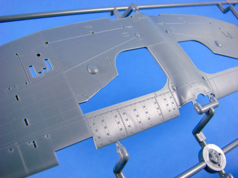
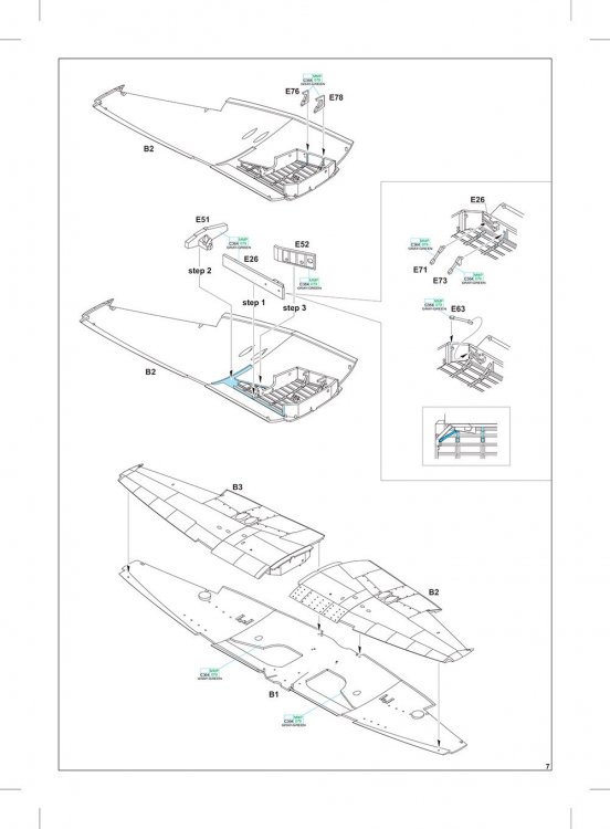
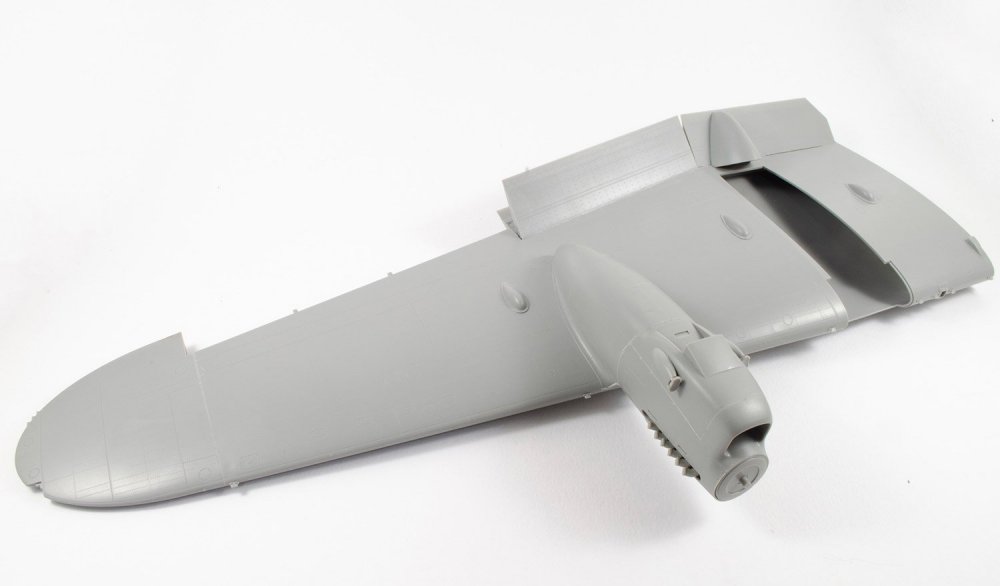
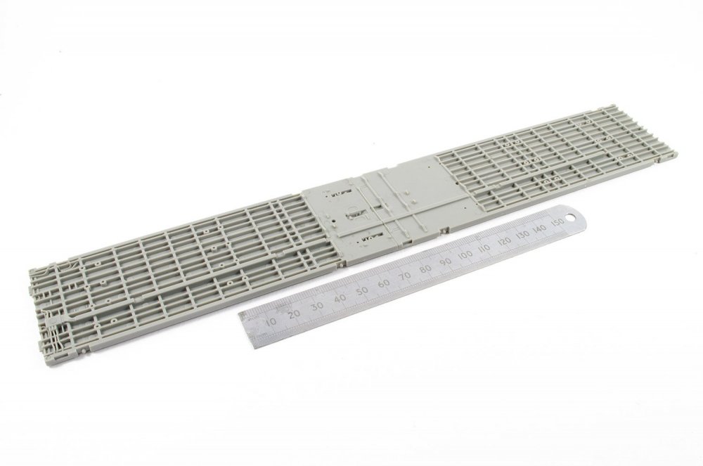
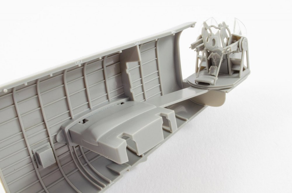
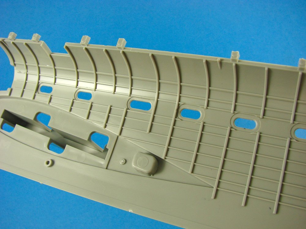
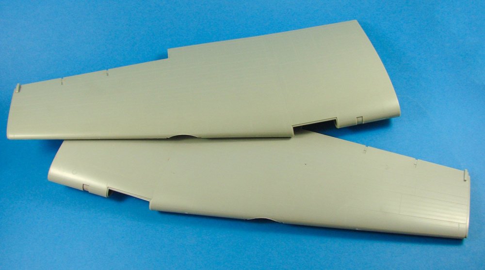
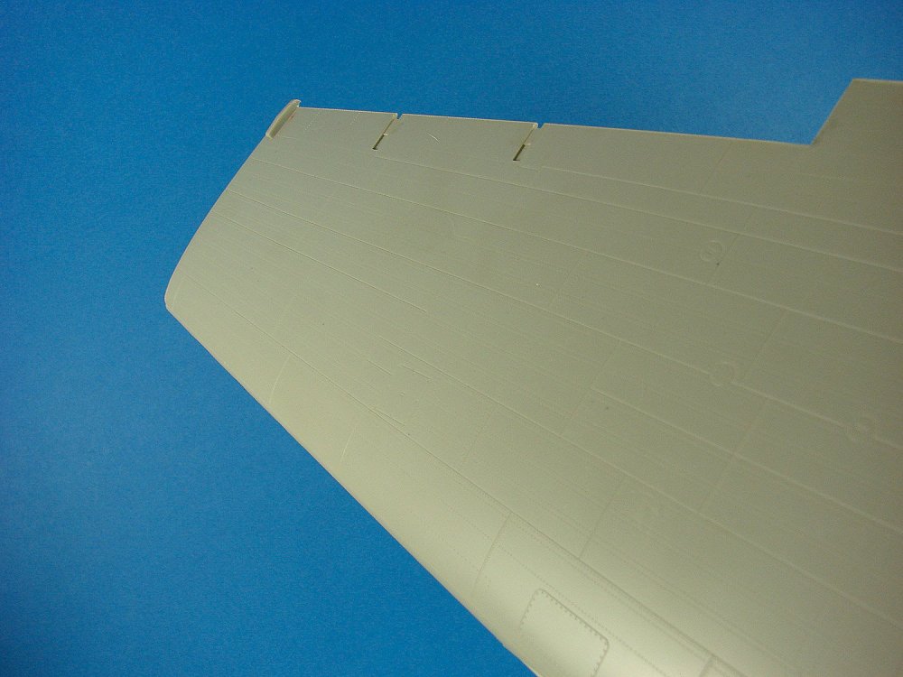
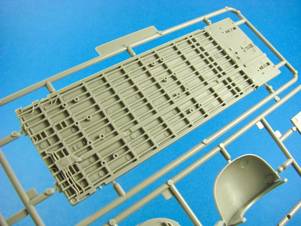
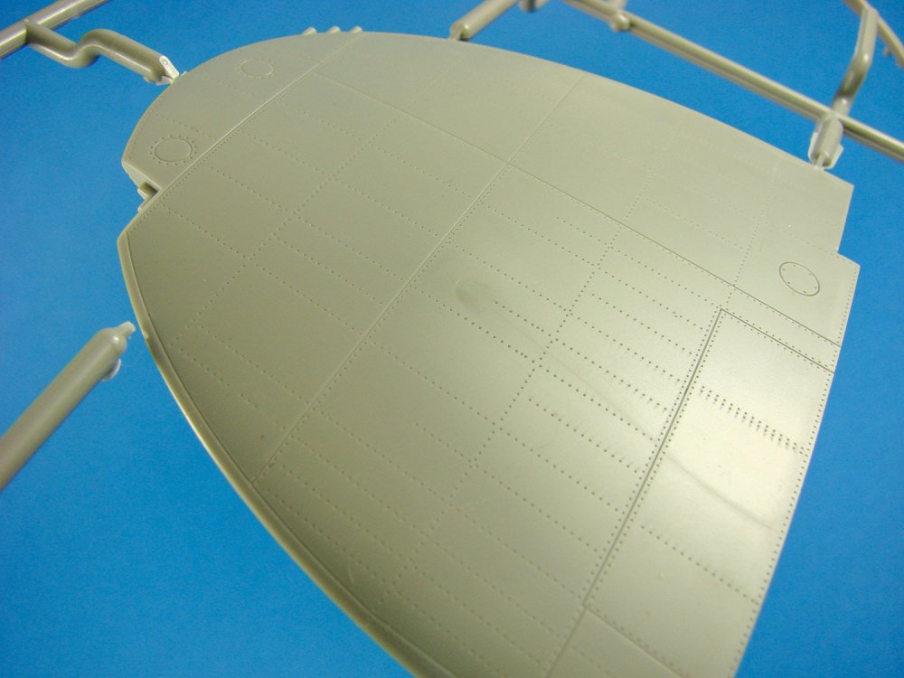
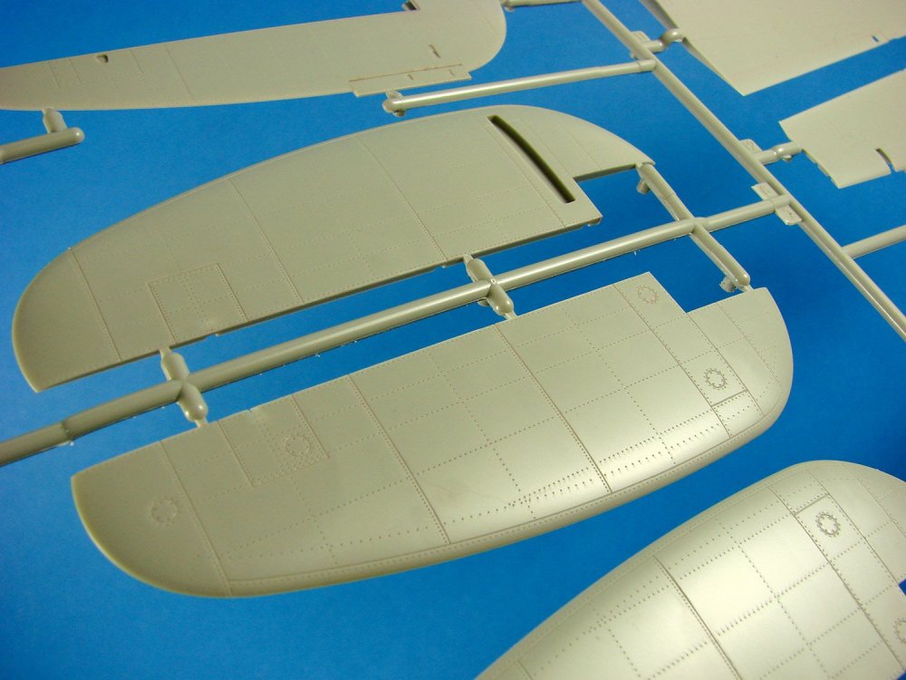
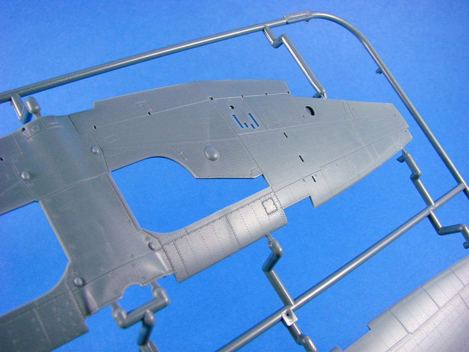
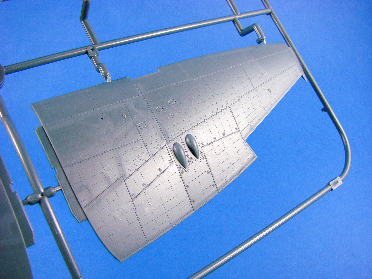
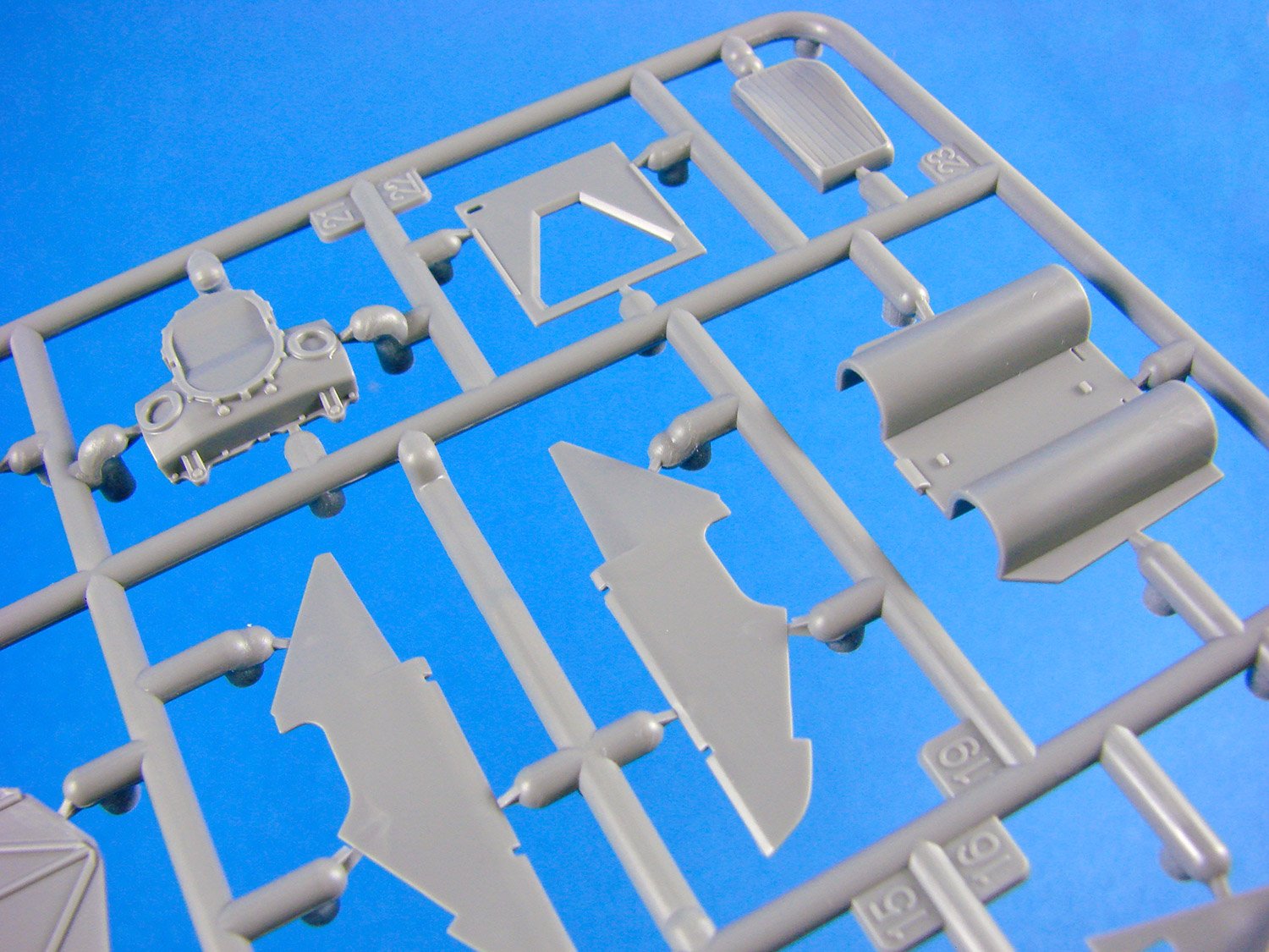
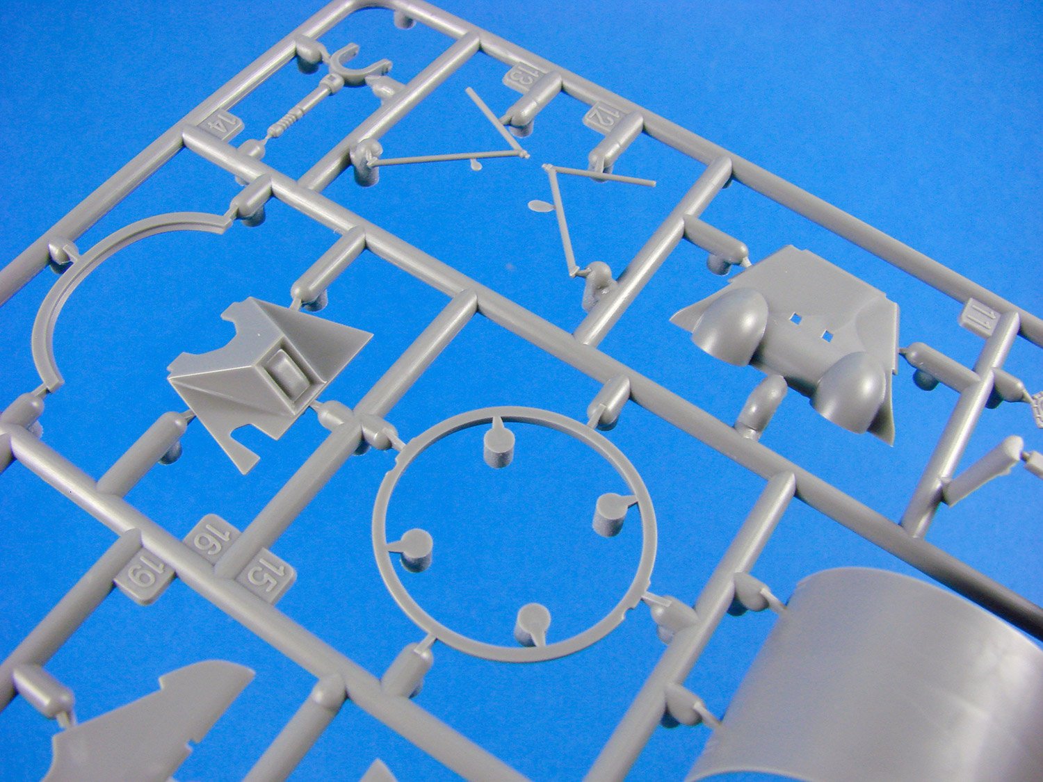
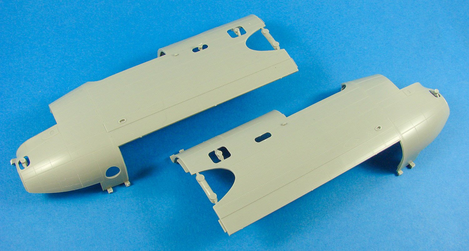
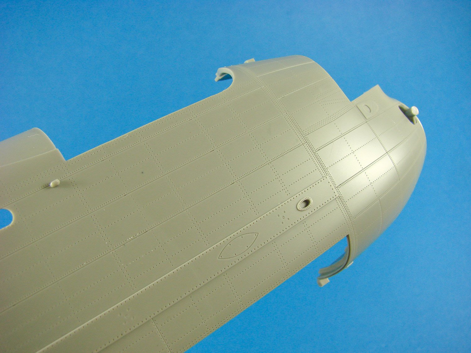
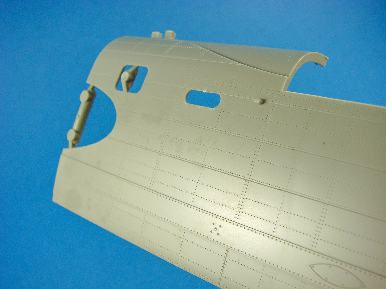
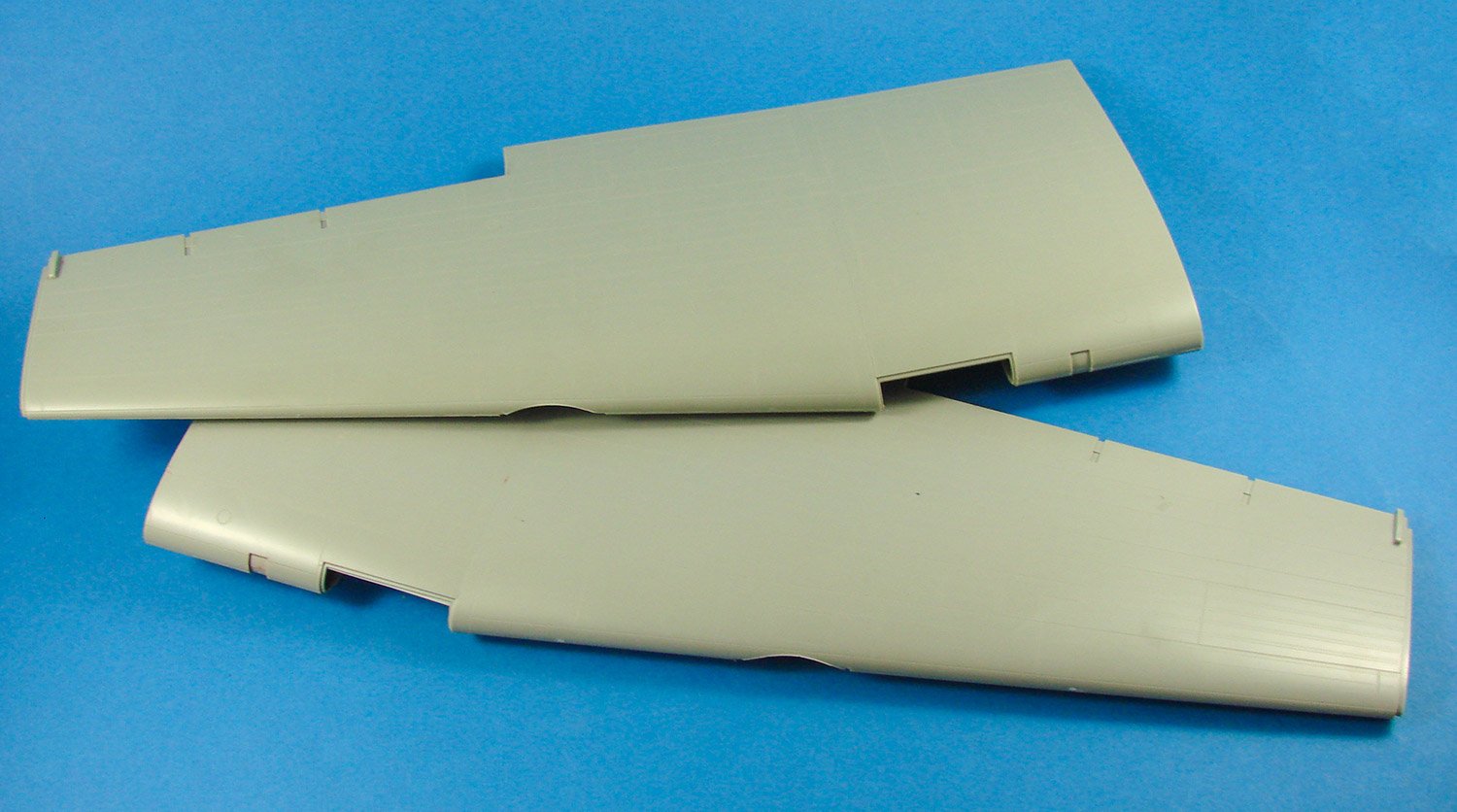
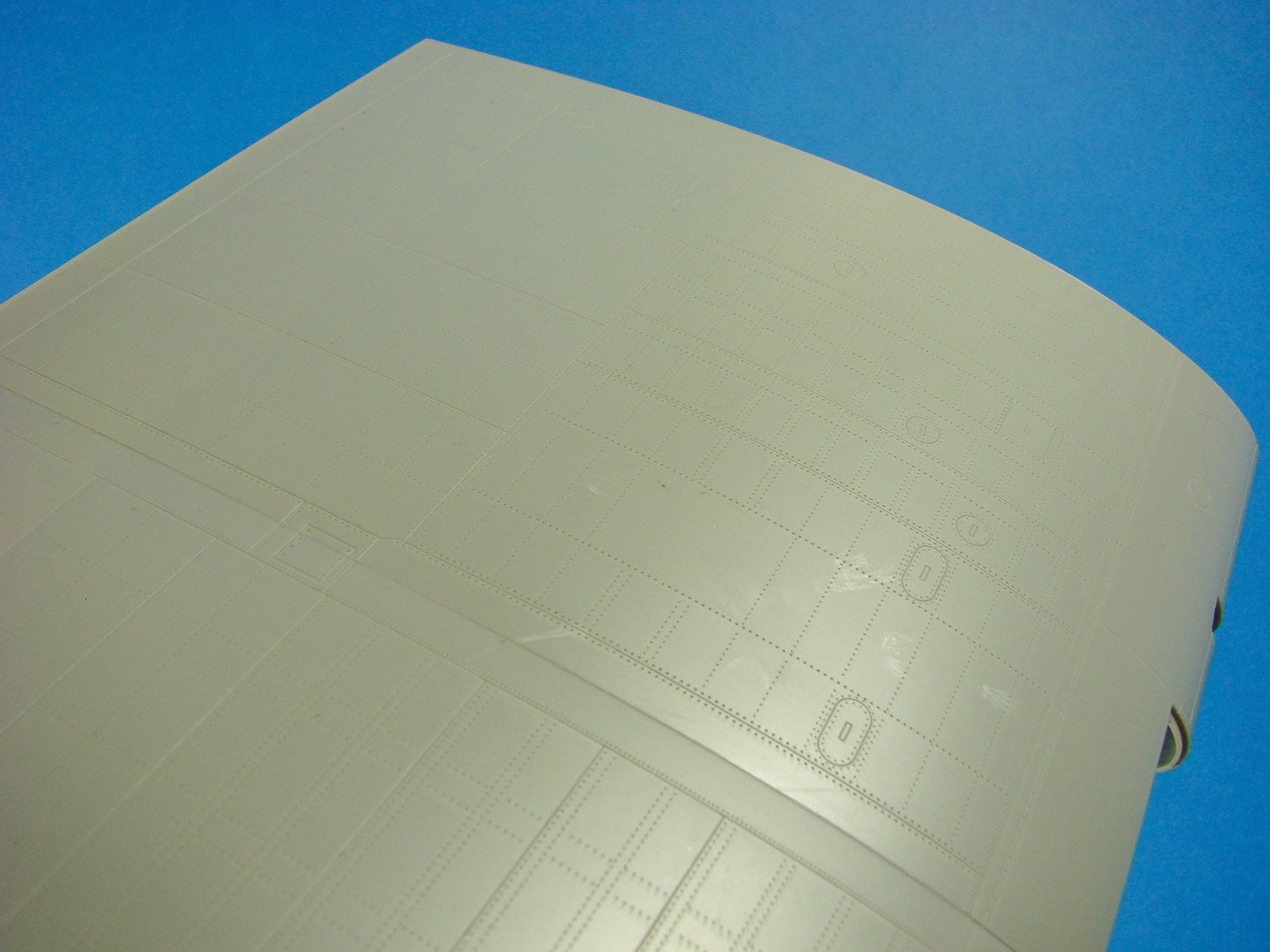
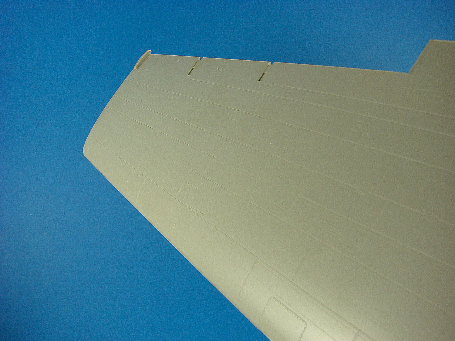
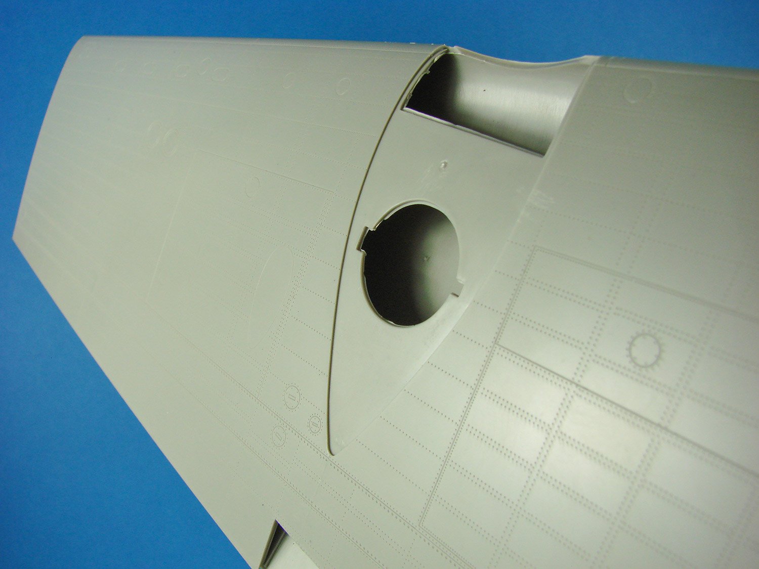
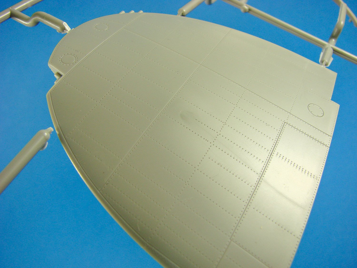
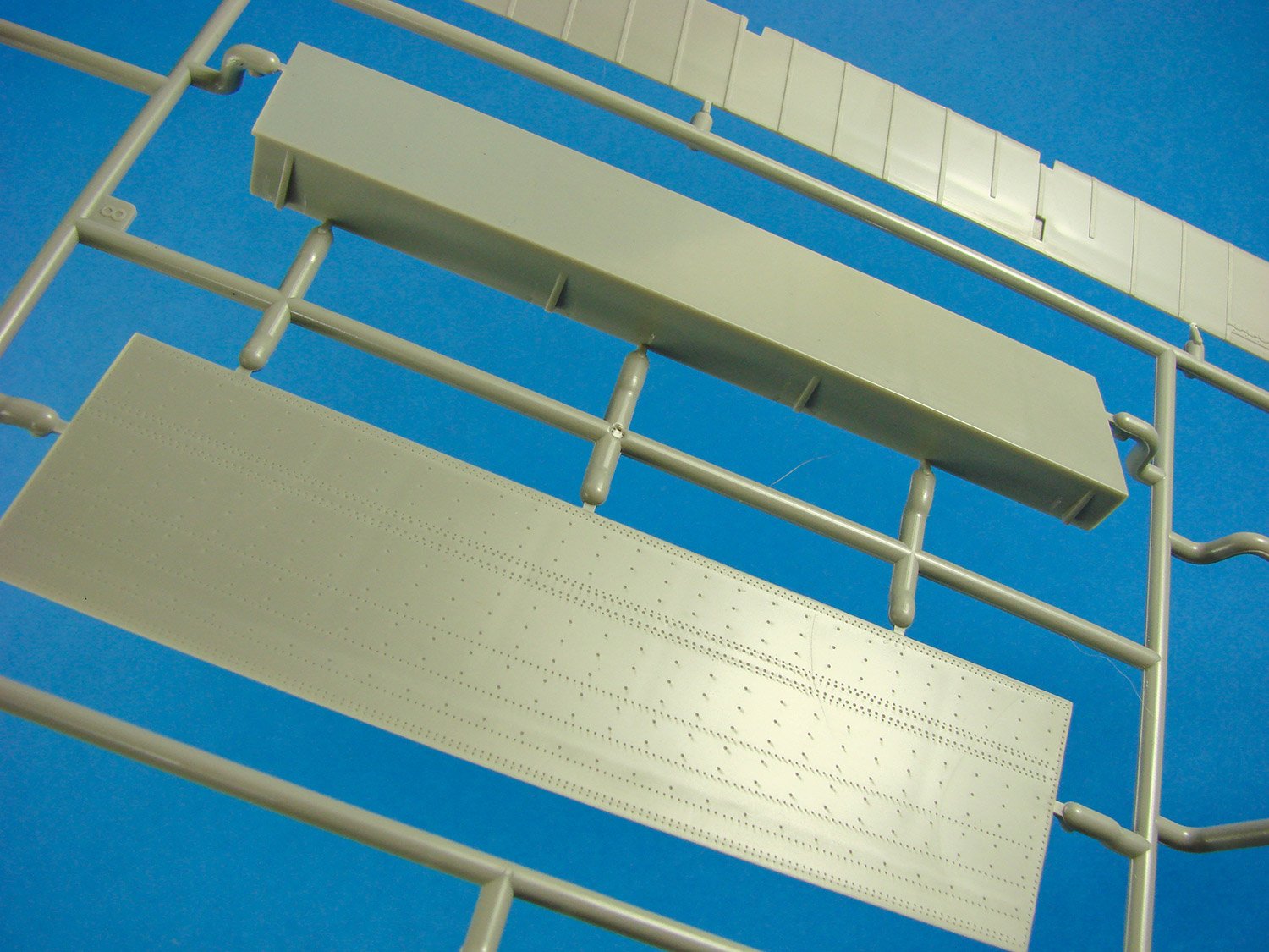
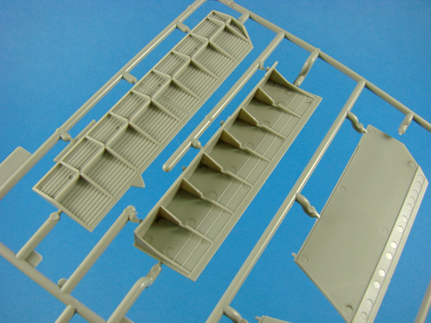
Here we have the wing panels. The lower wing is moulded as a full-span unit, with integral main gear openings. Note that the ailerons are moulded separately, and Eduard has thankfully chosen to mould the gun fairings separately to the wing, unlike on their Spitfire series of kits. This means that there are now no awkward seams to align and remove on the new Tempest kit. Surface details really are very, very nice, with finely recessed panel lines, subtle recessed rivets and fasteners, as well as access panel details. Shell ejection chutes are moulded open, and recesses are moulded into which the lower landing light covers will sit, so these aren’t fixed from the inside.

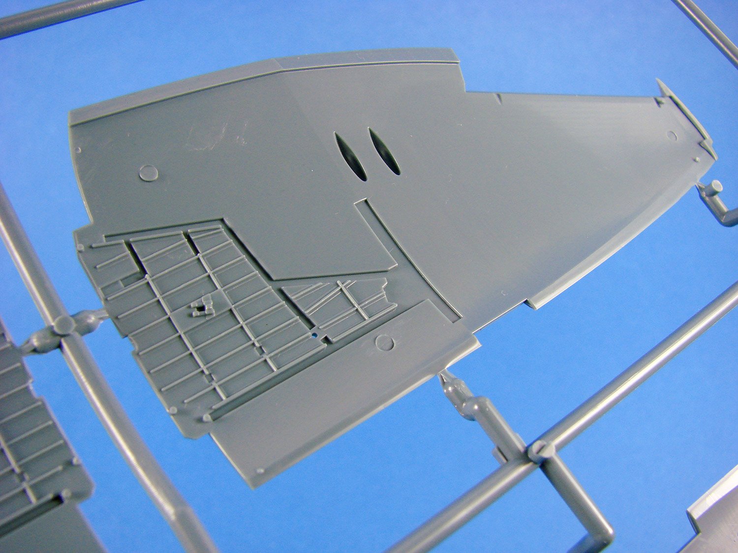
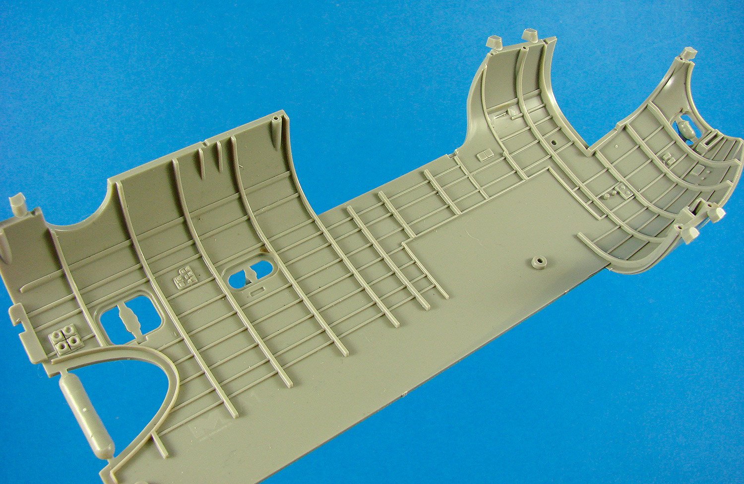
The upper wing panels exhibit the same standard of detail, with well-defined gun blisters and surrounding access panels with their Dzuz fasteners. Tabs protrude from the wing joint, providing a solid connection point to the recesses inside the interior wing fairing of the fuselage halves. Flip the upper panels over and you’ll see the moulded details of the main gear bay ceilings. Again, this detail is sharp and looks excellent. Notice the main gear lock which is also moulded in situ.

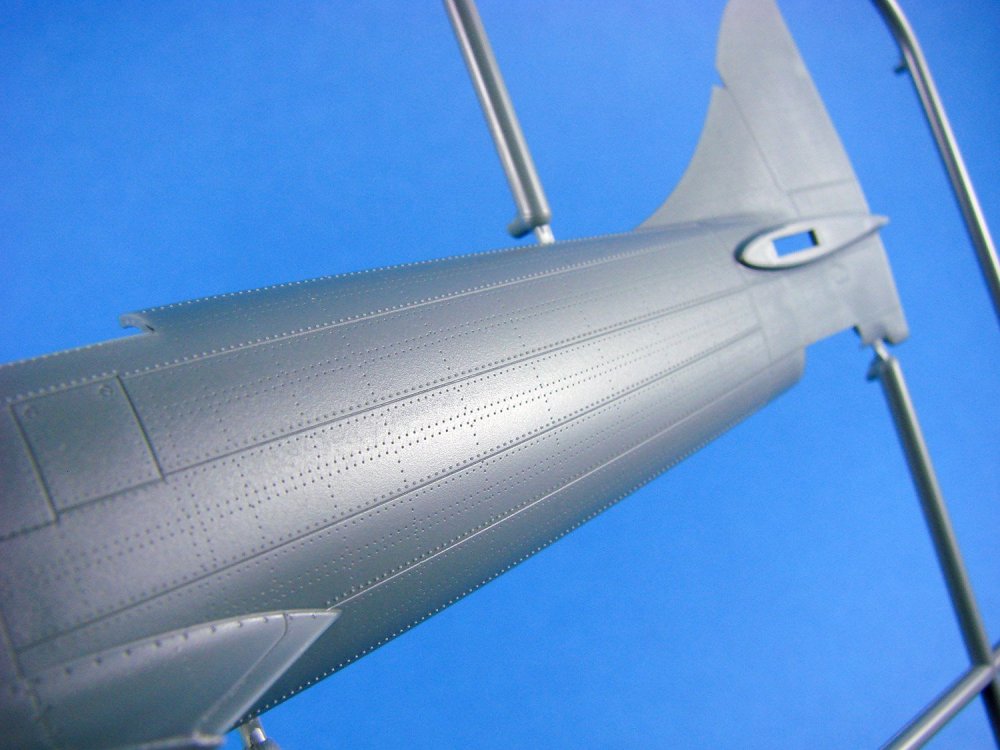
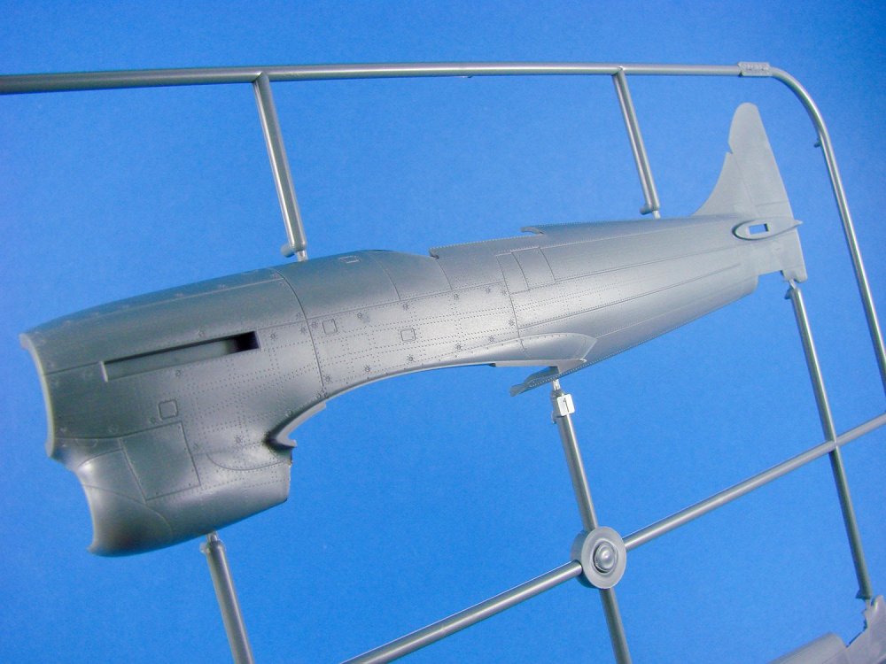
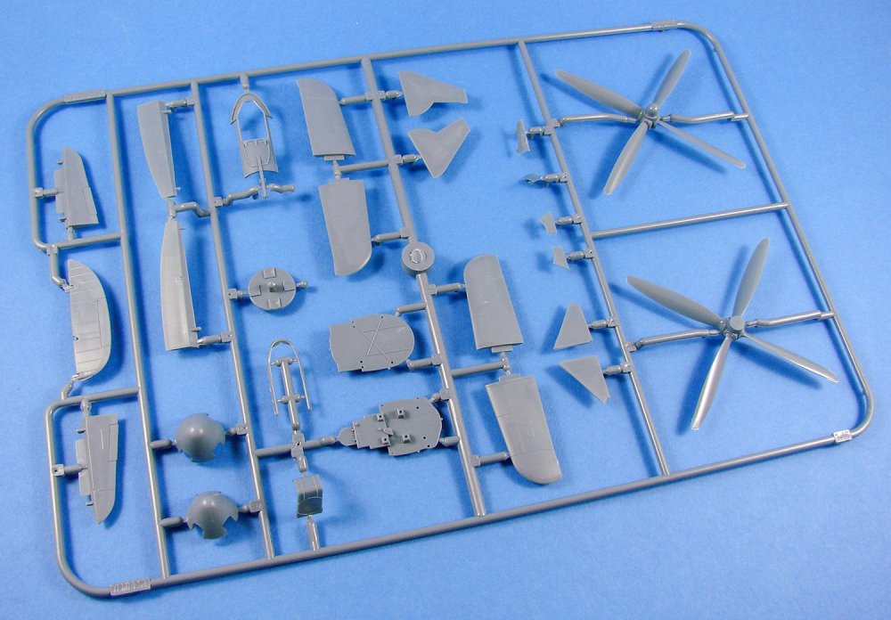
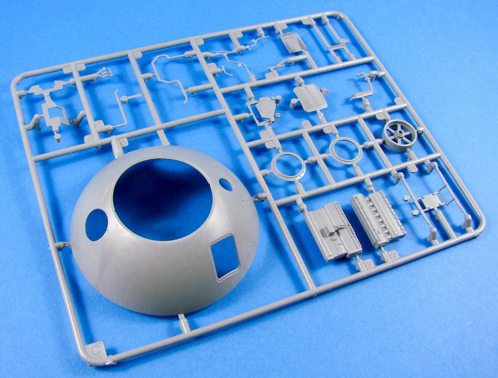
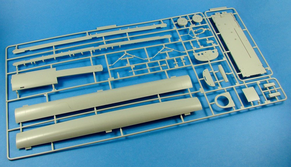
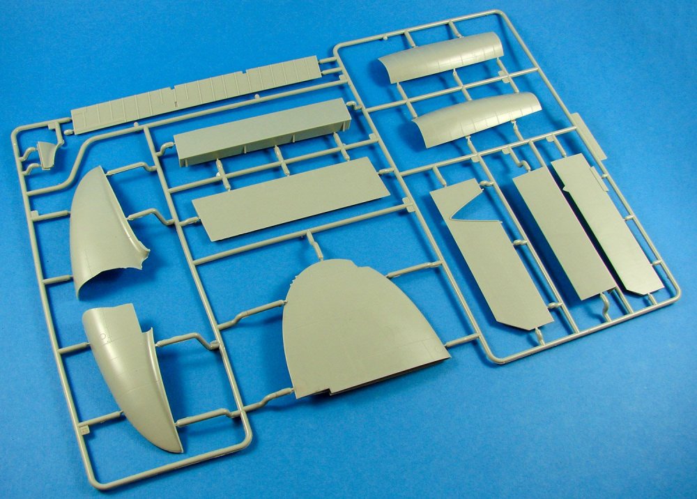
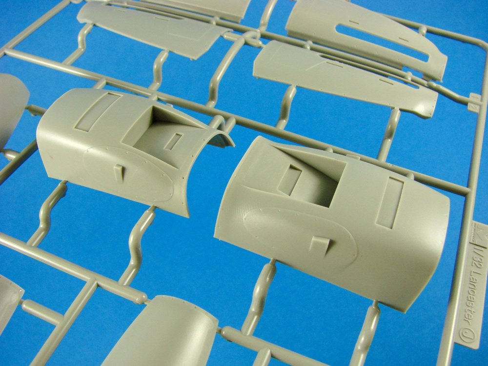
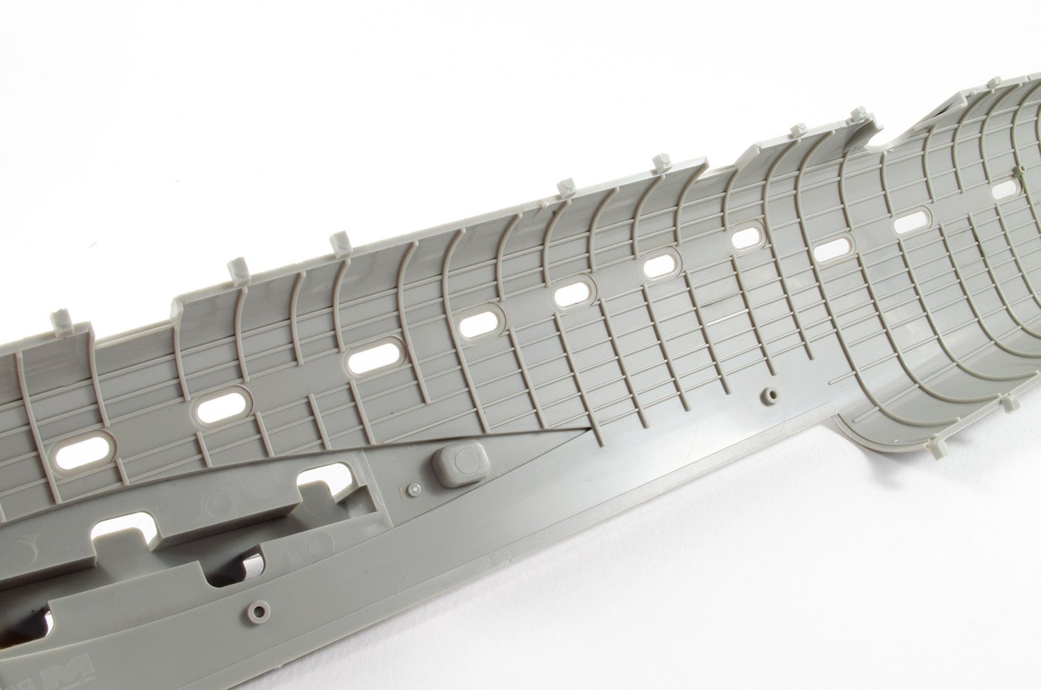
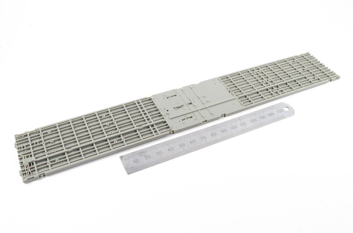
Sprue C

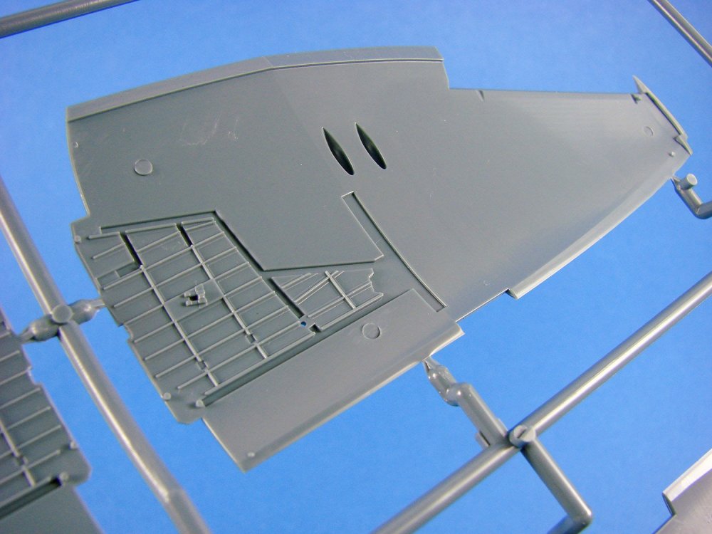
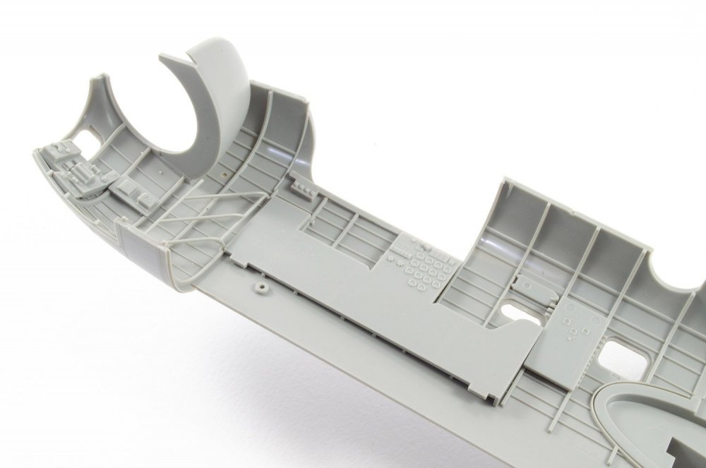
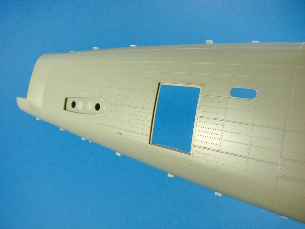
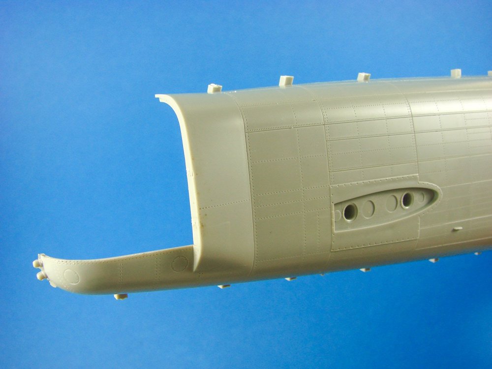
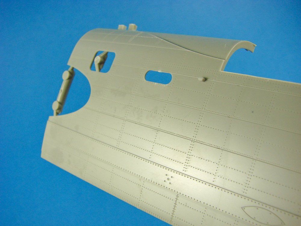
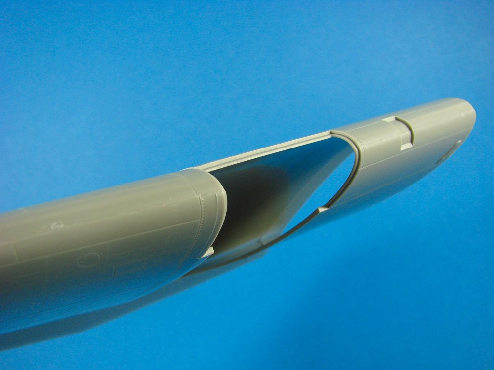
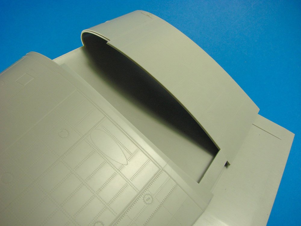
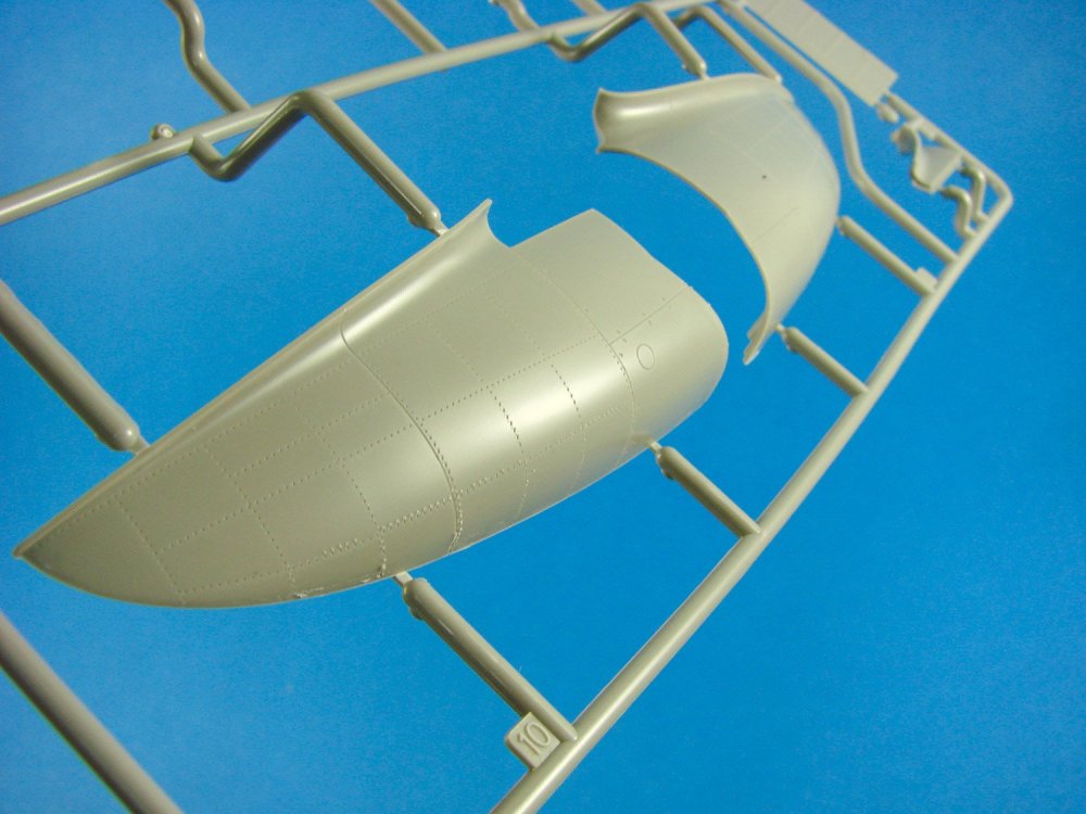
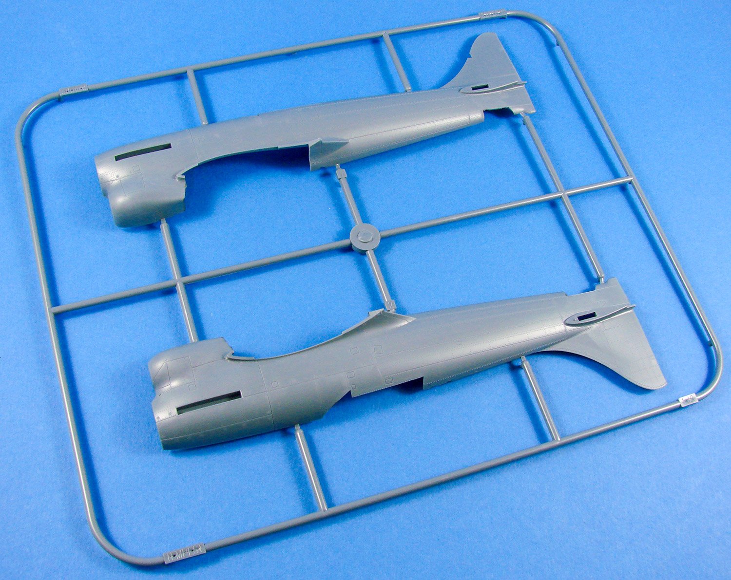
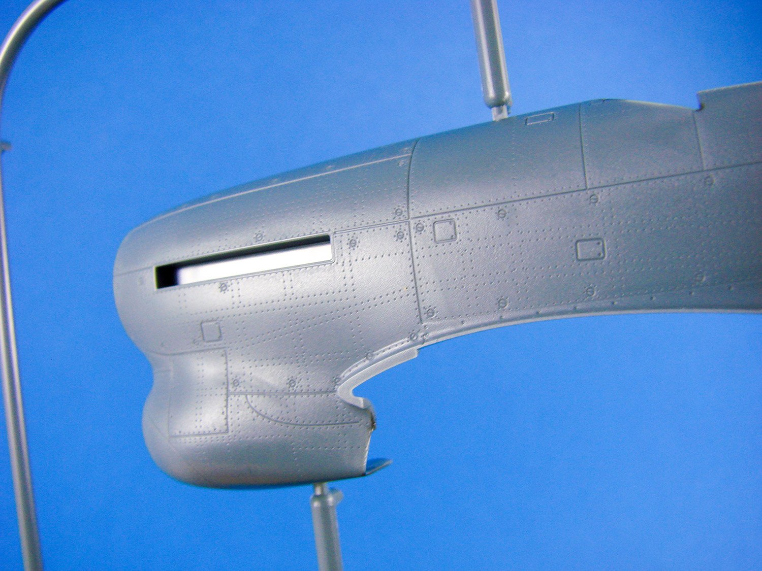
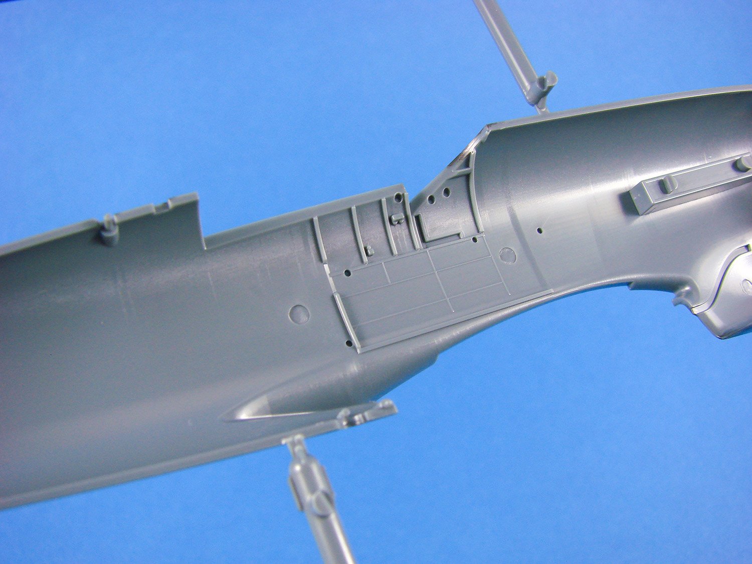
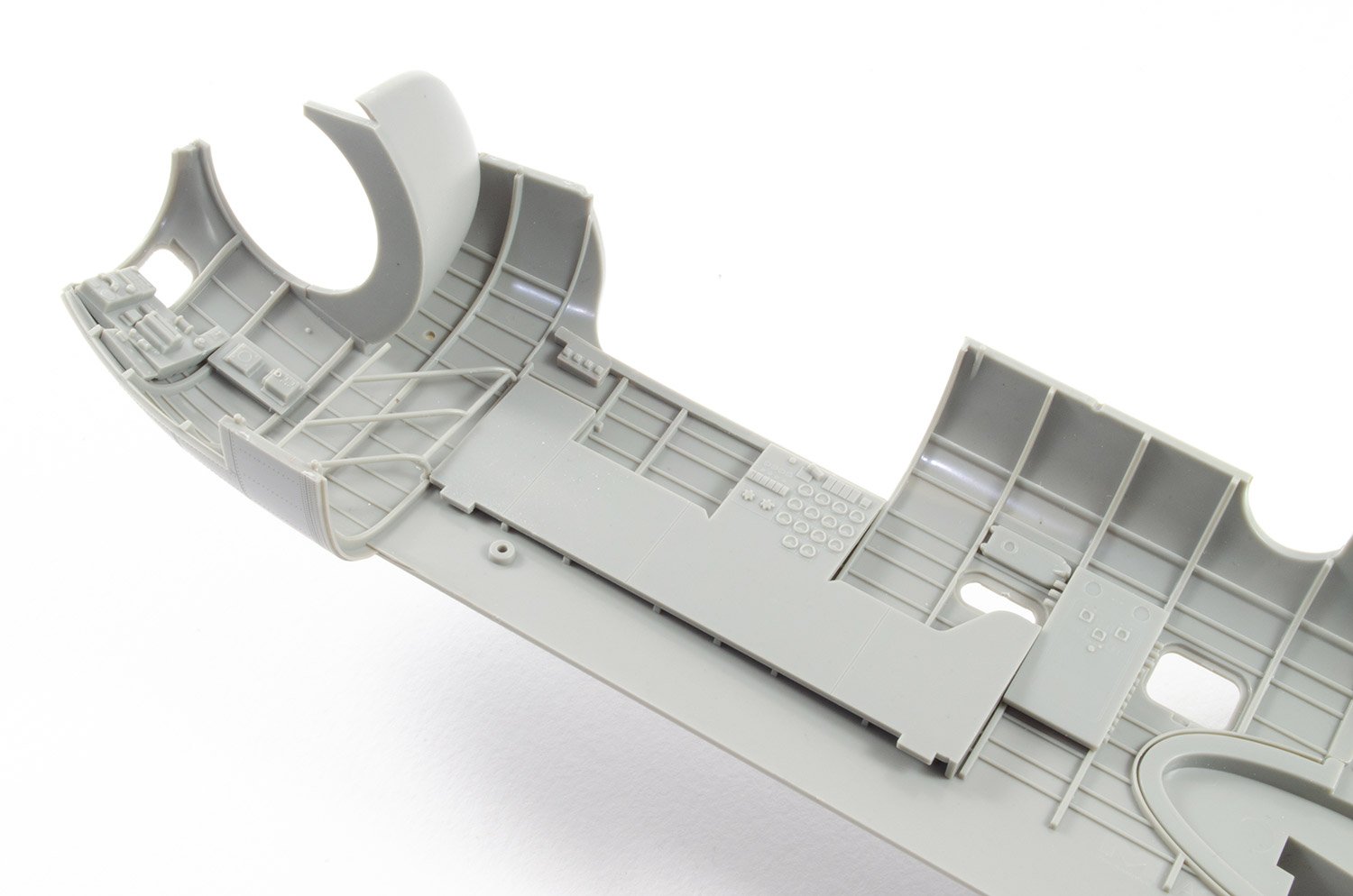
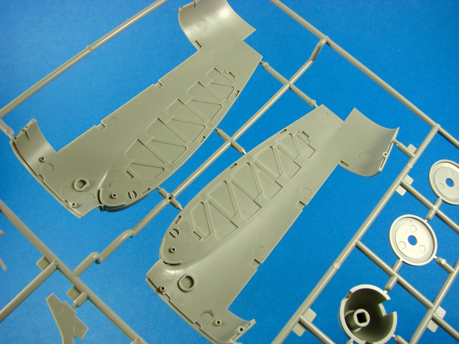
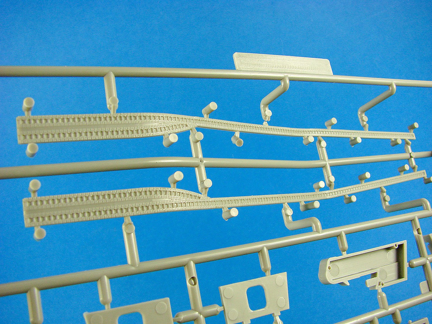
Eduard has moulded the fuselage as a full-length unit, minus the rudder. Recesses exist for fitting the rob of exhaust manifolds, with no separate box needing to be glued from within. Fine panel lines and Dzuz fasteners adorn the cowl area. Note that the upper turtle deck is separately moulded to the fuselage, meaning that there are no tricky seams to remove when the fuselage is closed up. The rest of the fuselage not only has the same superbly recessed panel lines and rivets, but also key rows of raised rivets on the overlapping panels on the rear fuselage. I’m very pleased to see the inclusion of these. If you look at the tail joint line, you’ll see no fishplate detail. This release includes them as PE parts, which will certainly looks sharp when installed.

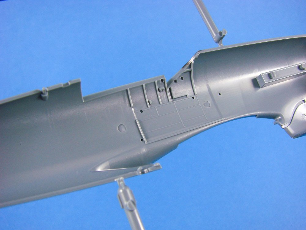
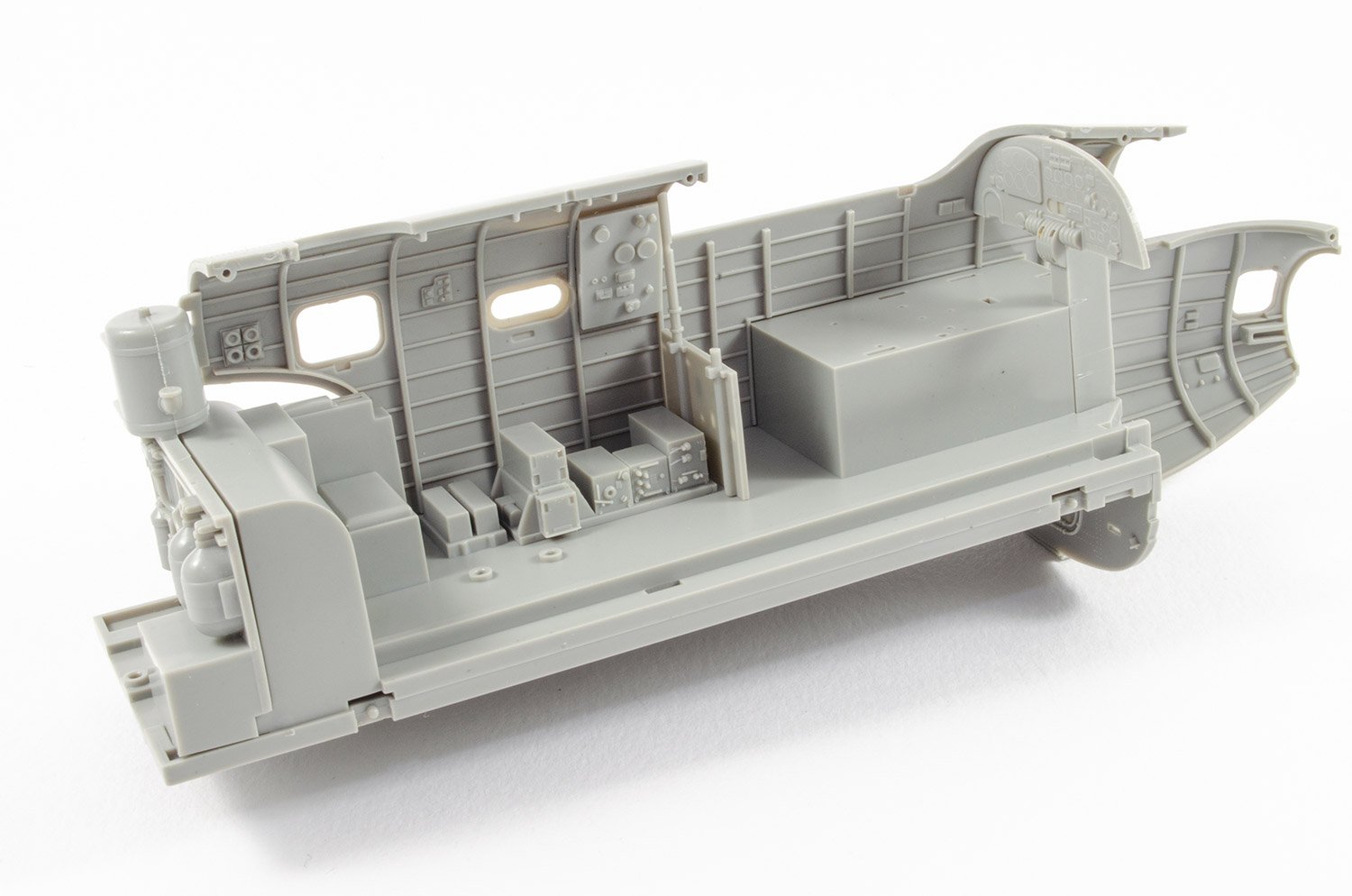
Internally, there is moulded cockpit wall detail which will supplement the cockpit tub, when installed. This detail consists of formers, electrical boxes etc. Detail is also provided in the tail wheel well area.

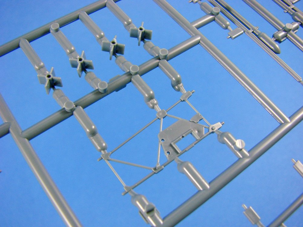
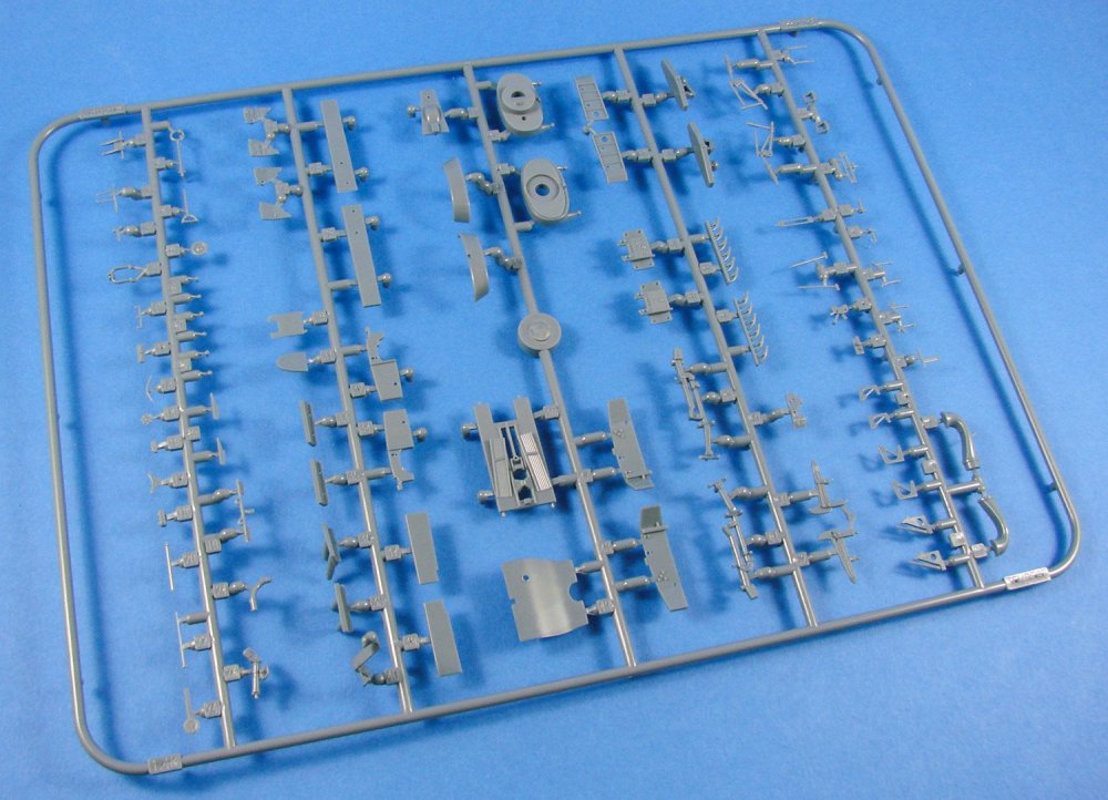
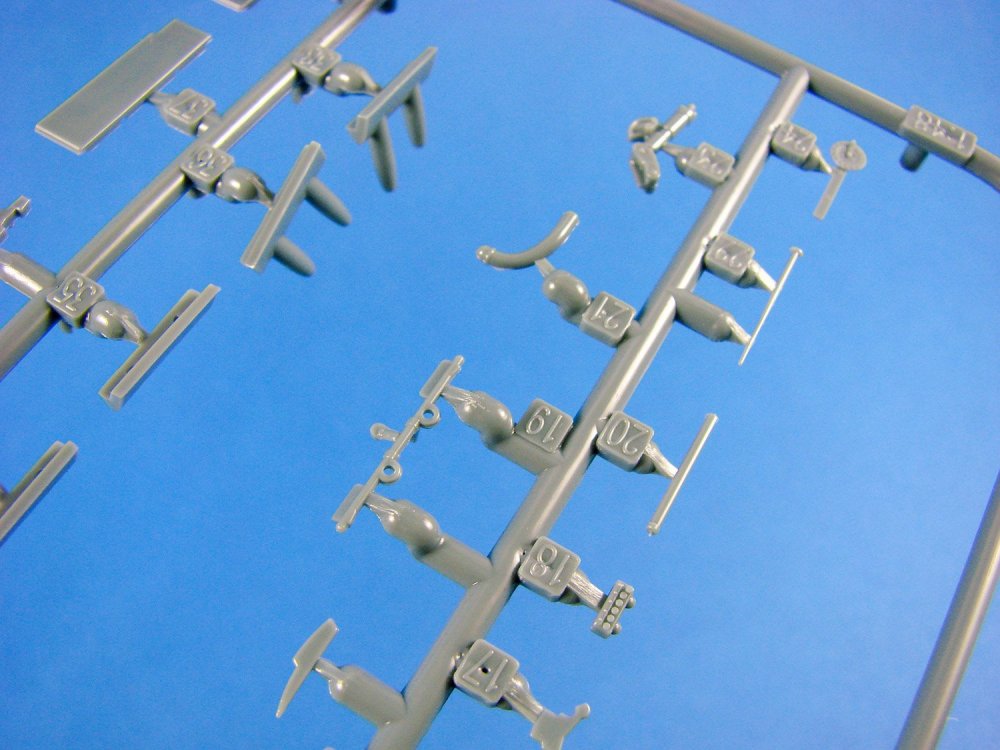
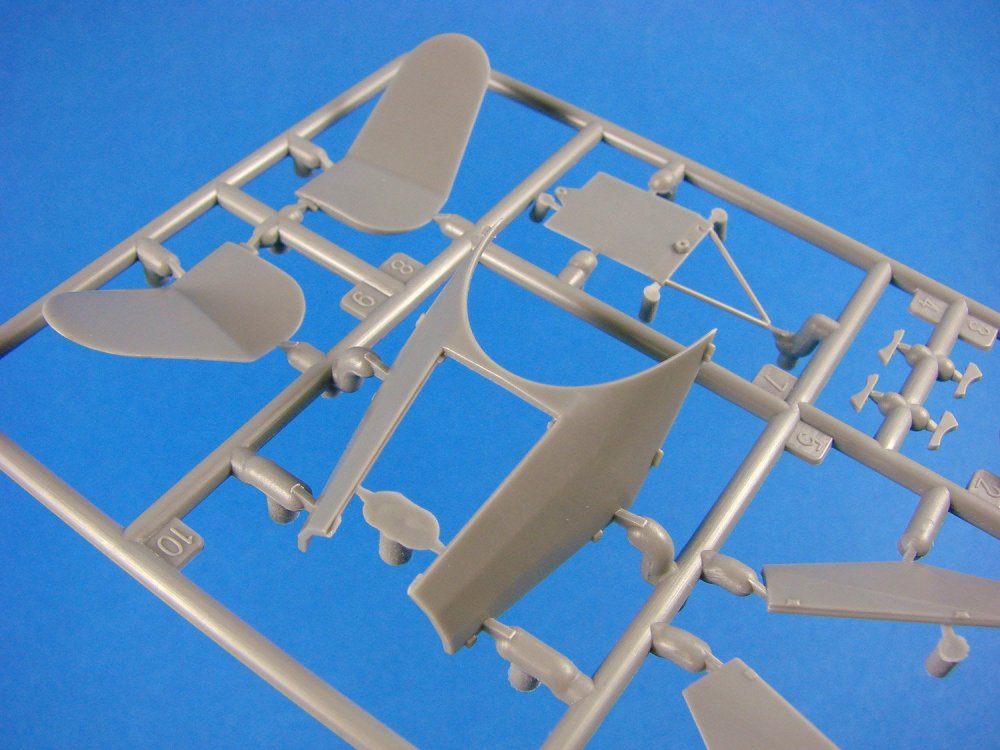
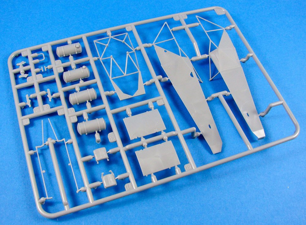
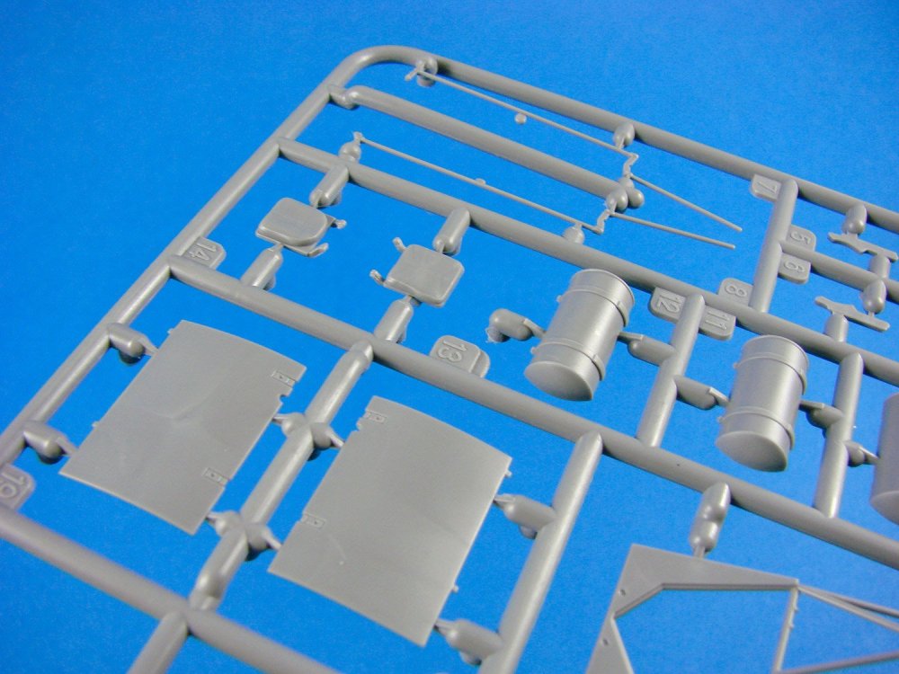
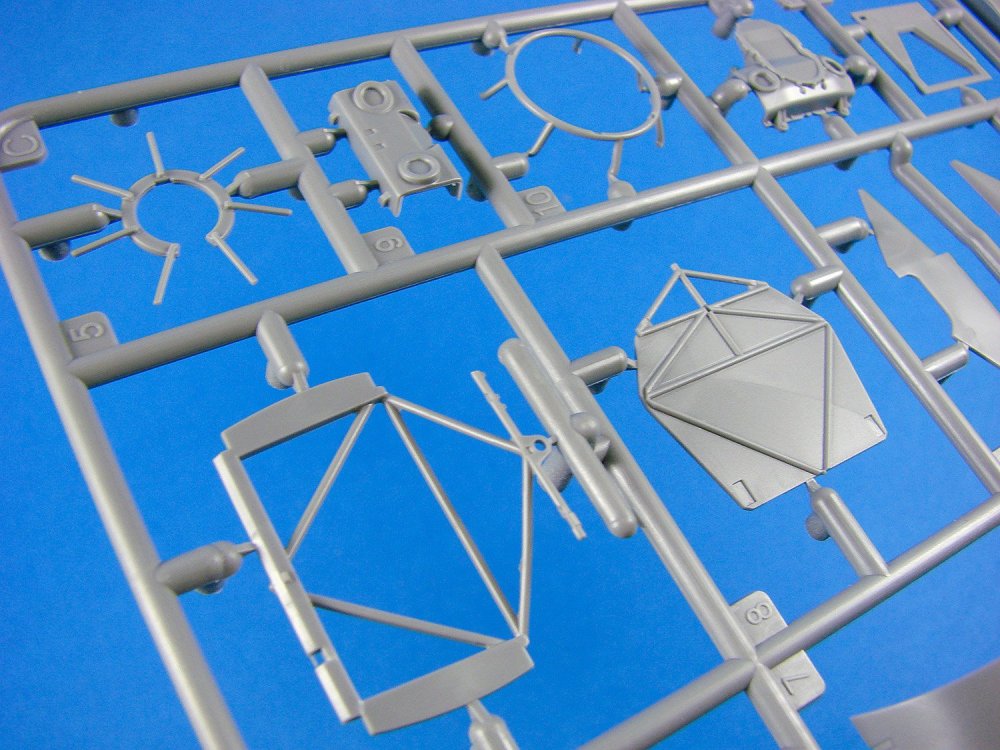
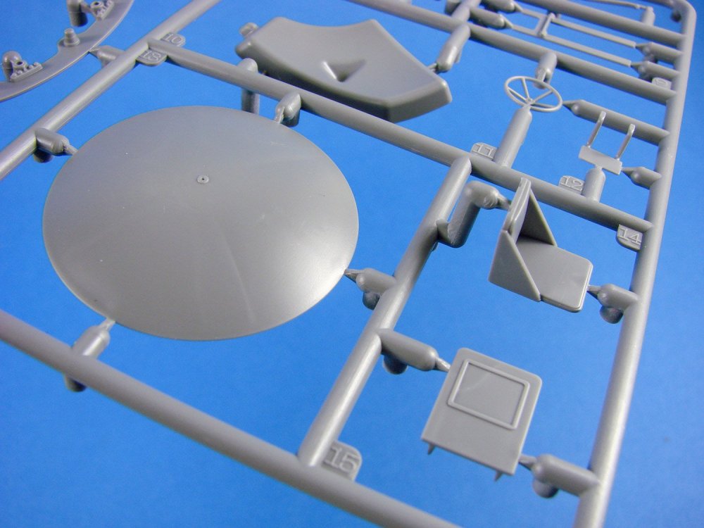
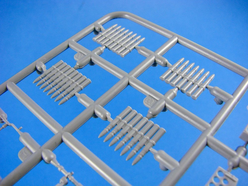
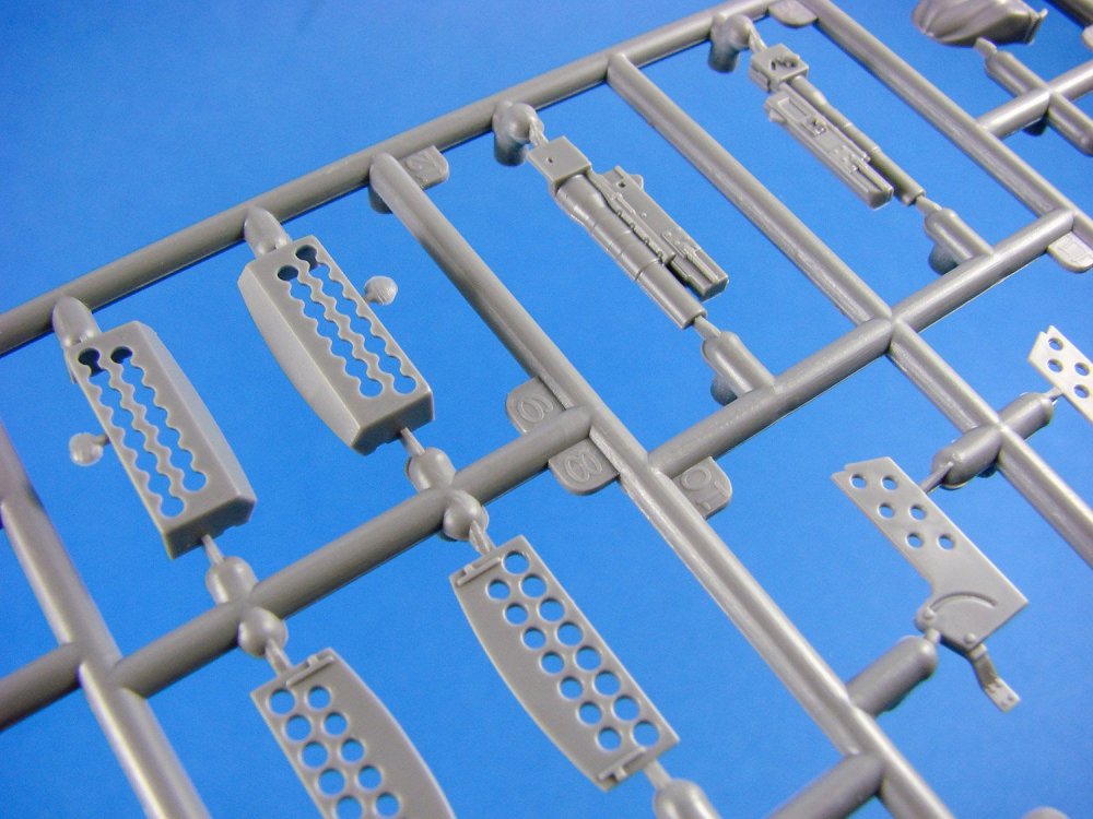
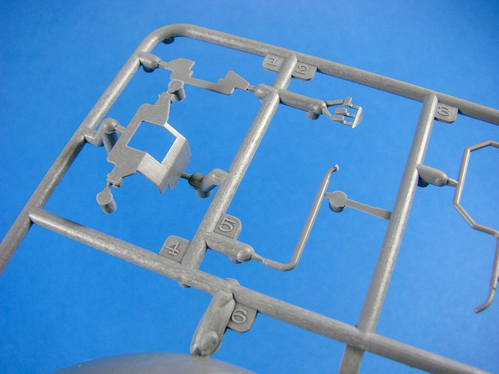
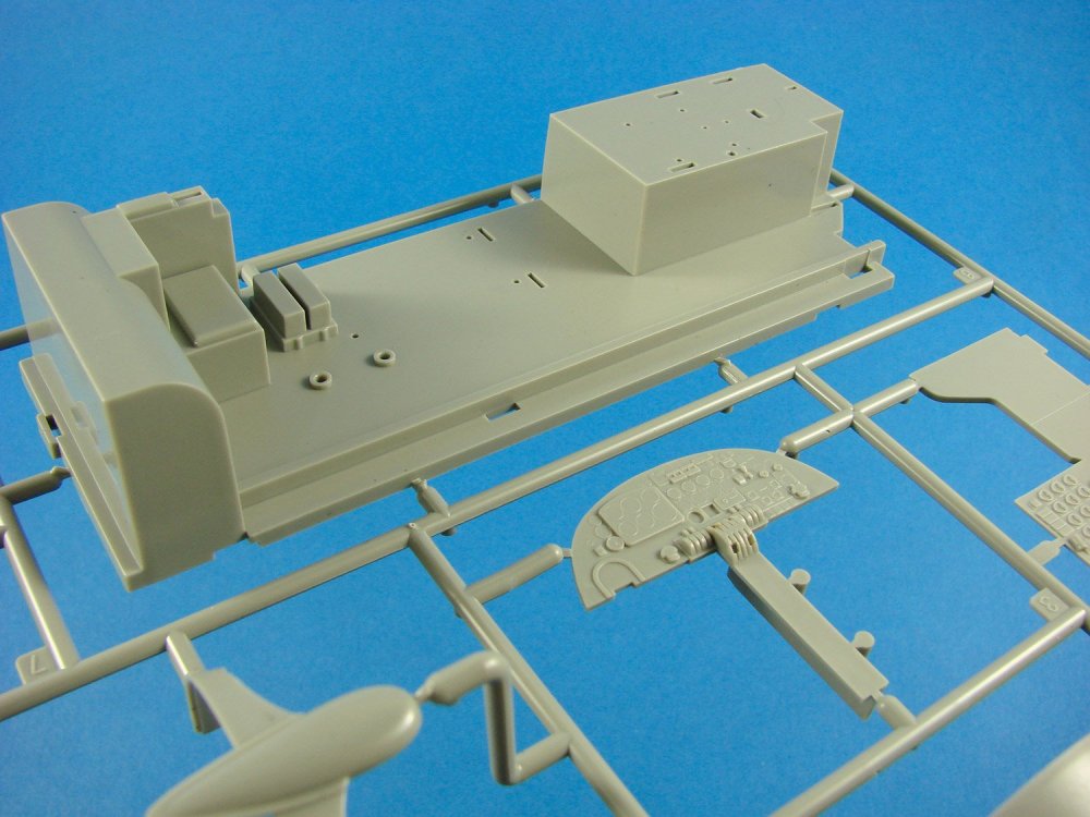
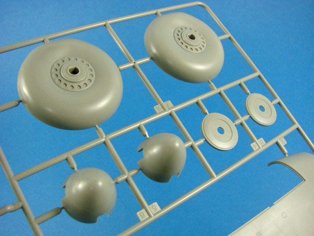
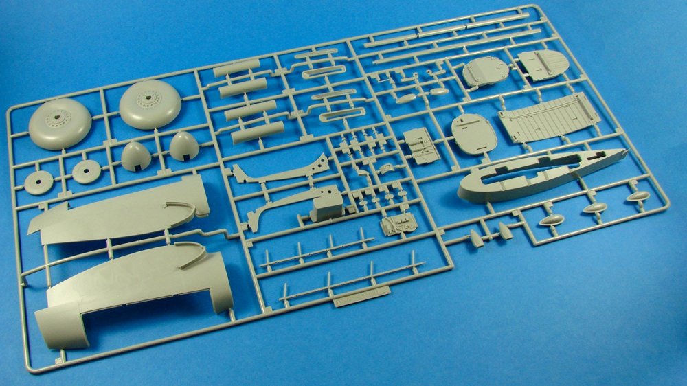
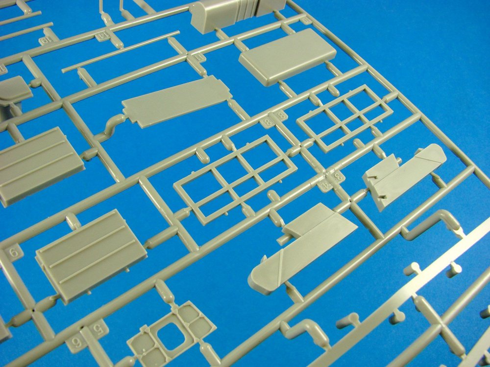
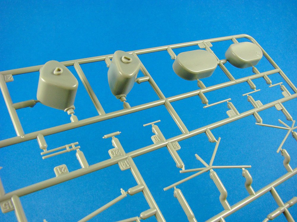
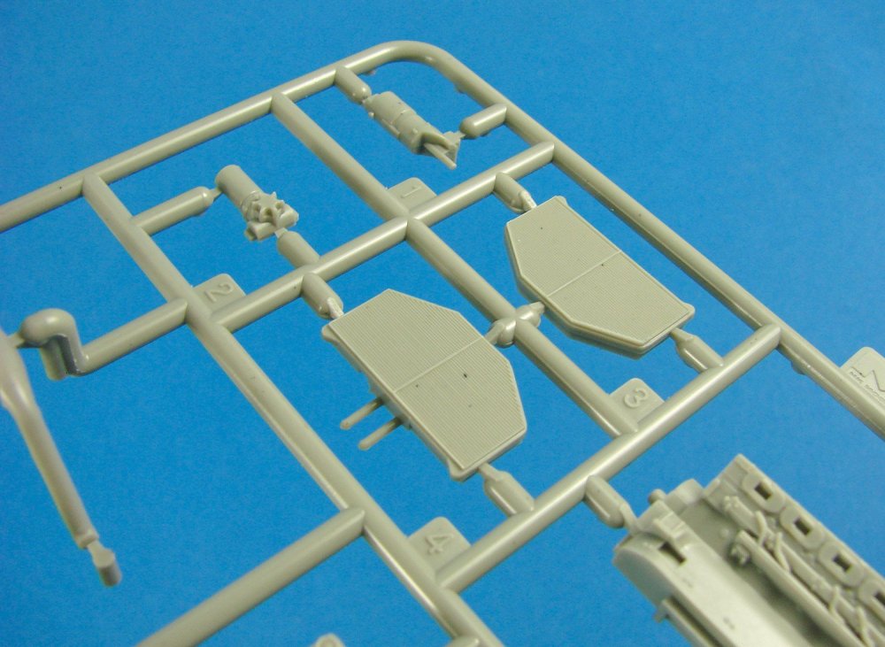
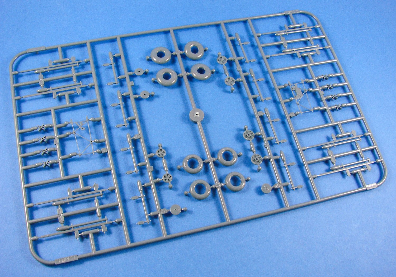
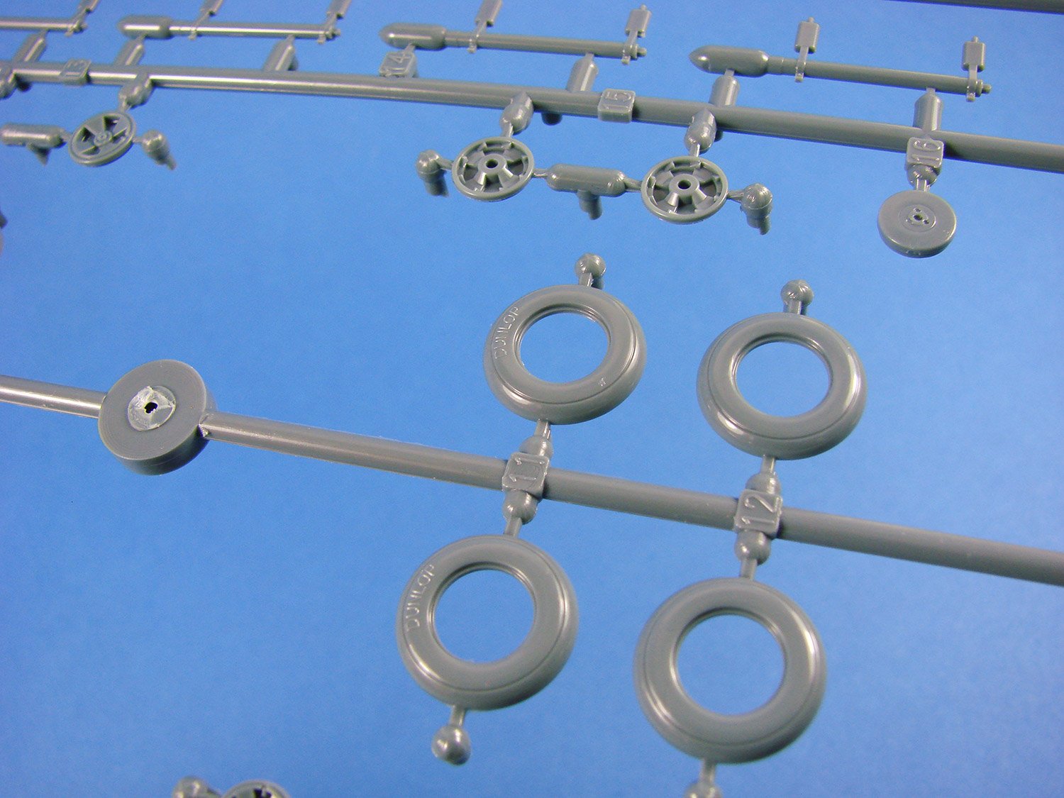
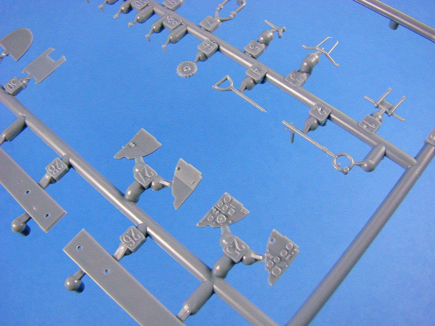
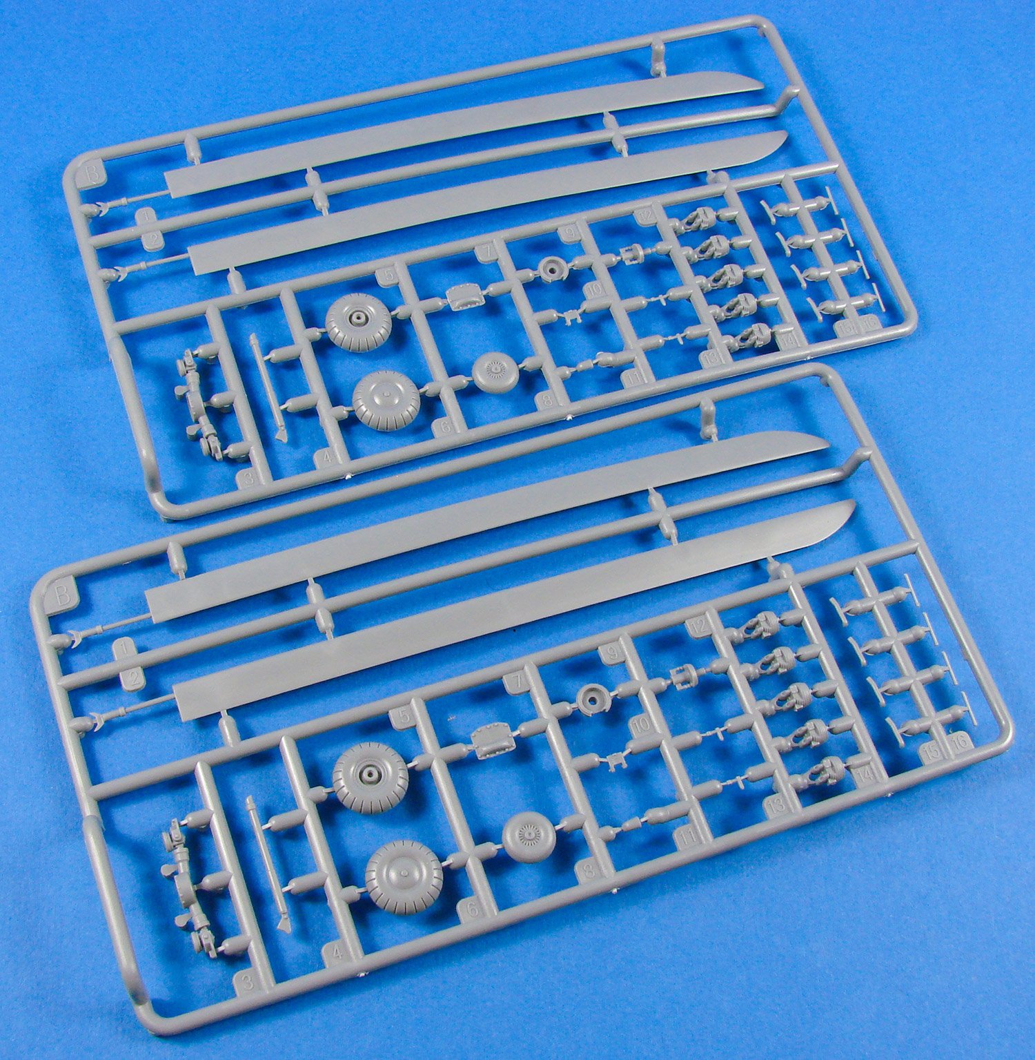
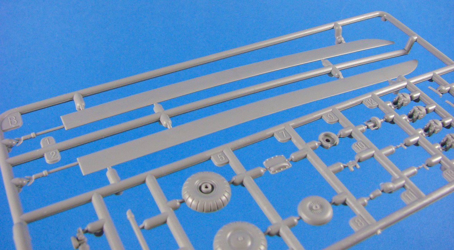
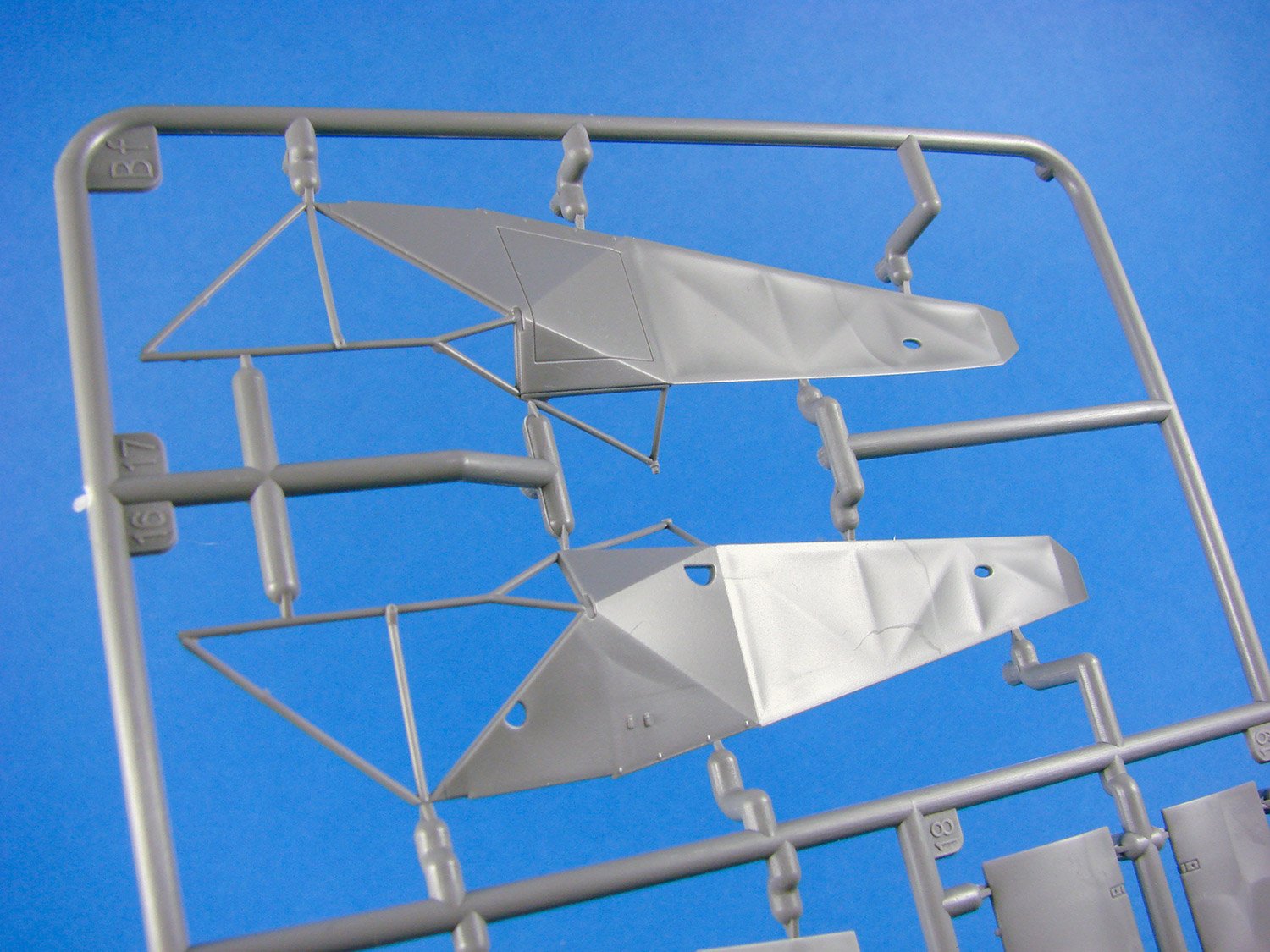
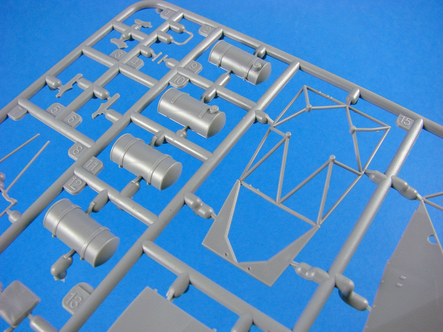
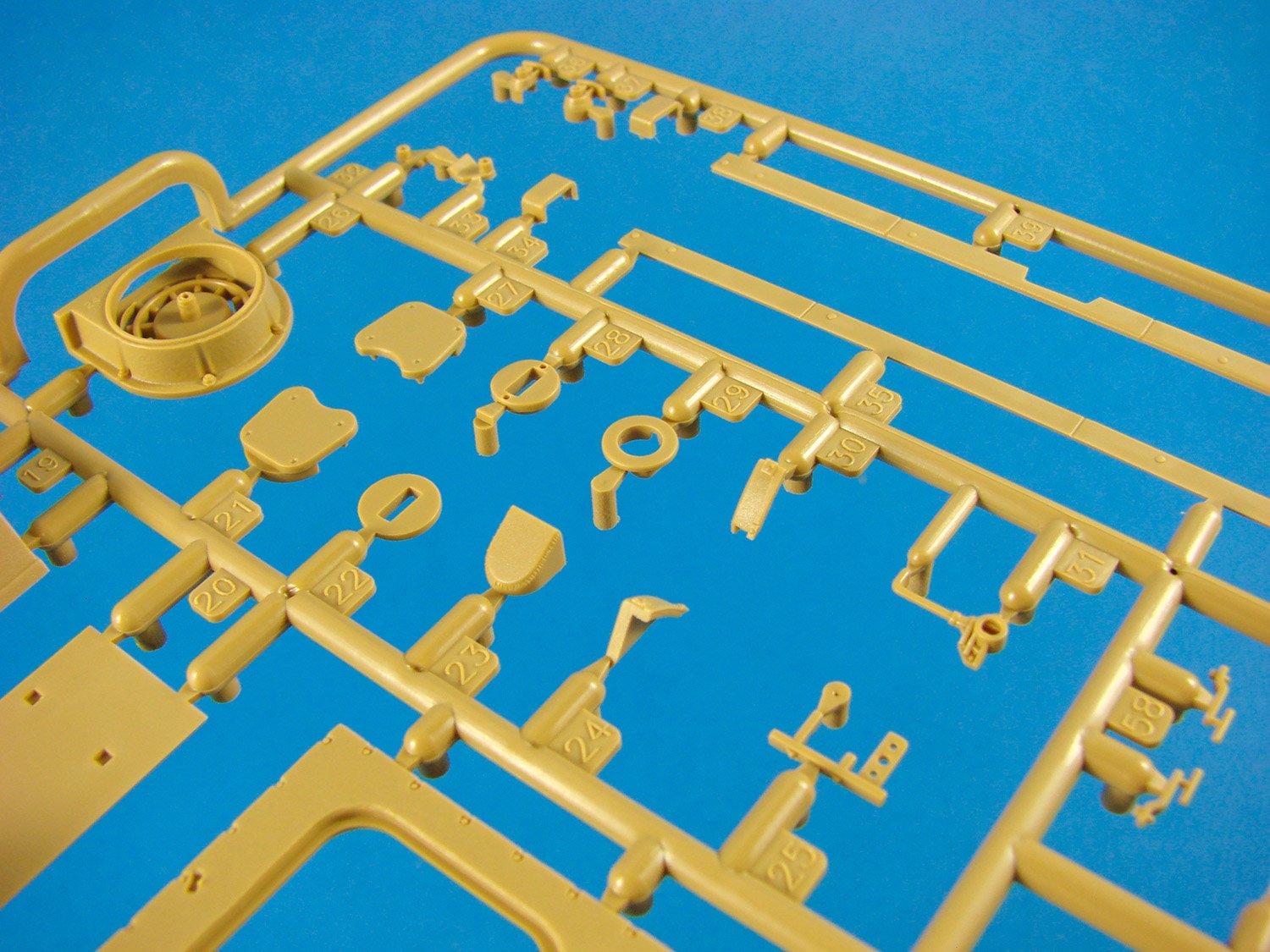
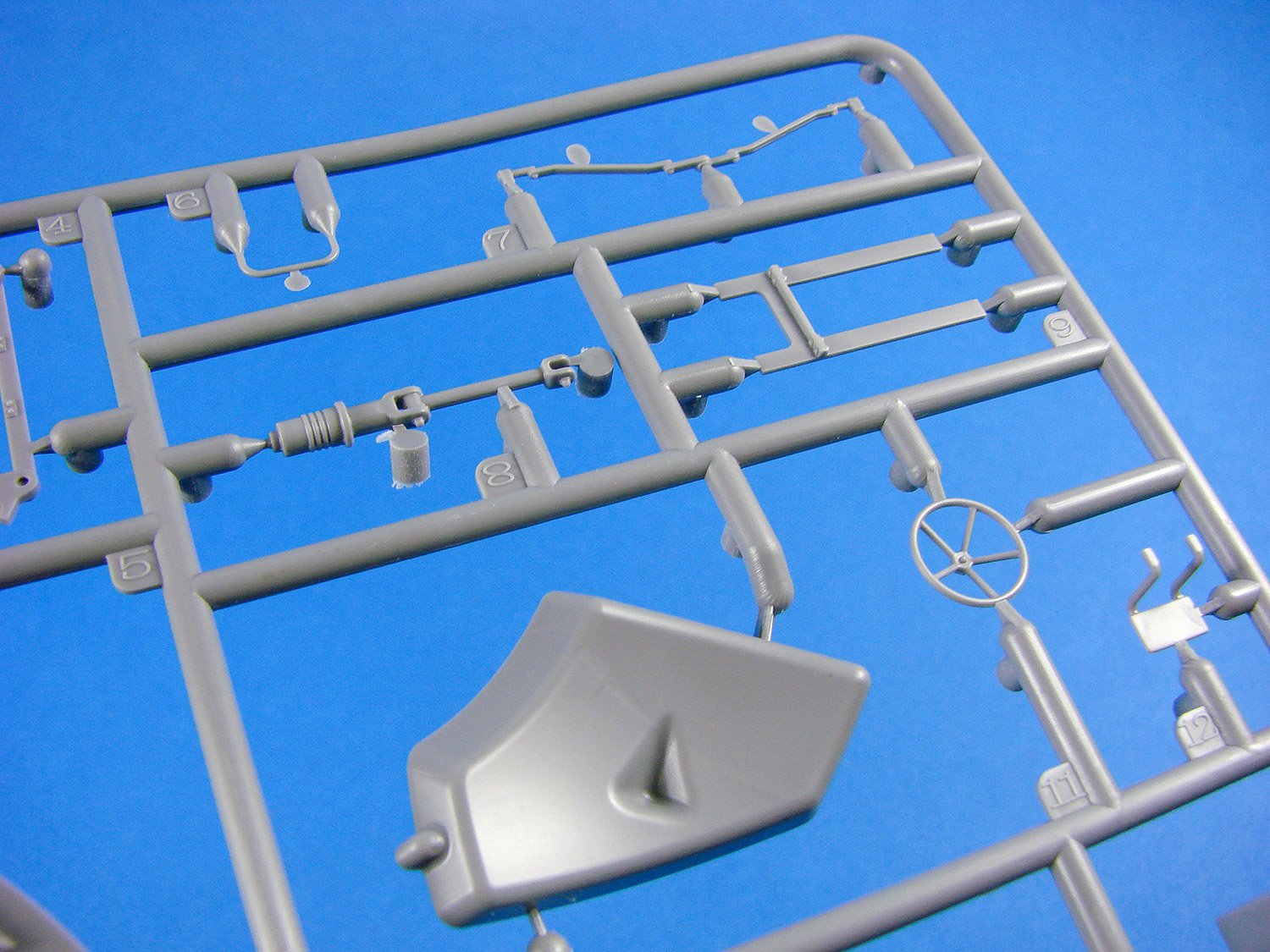
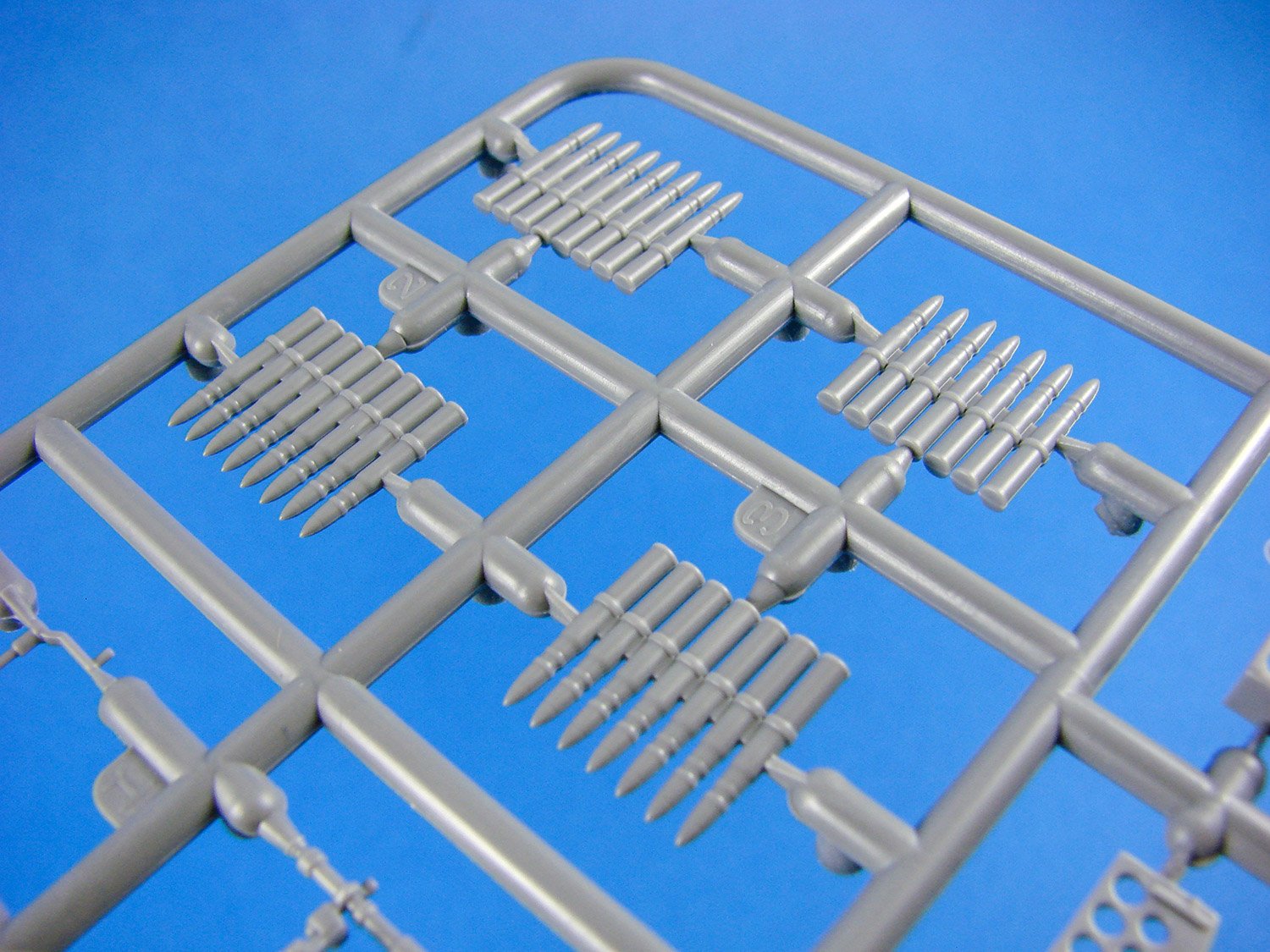
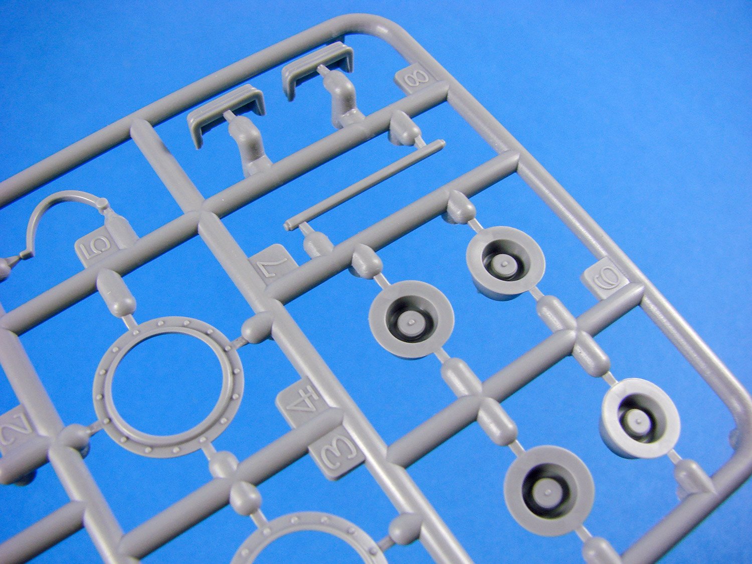
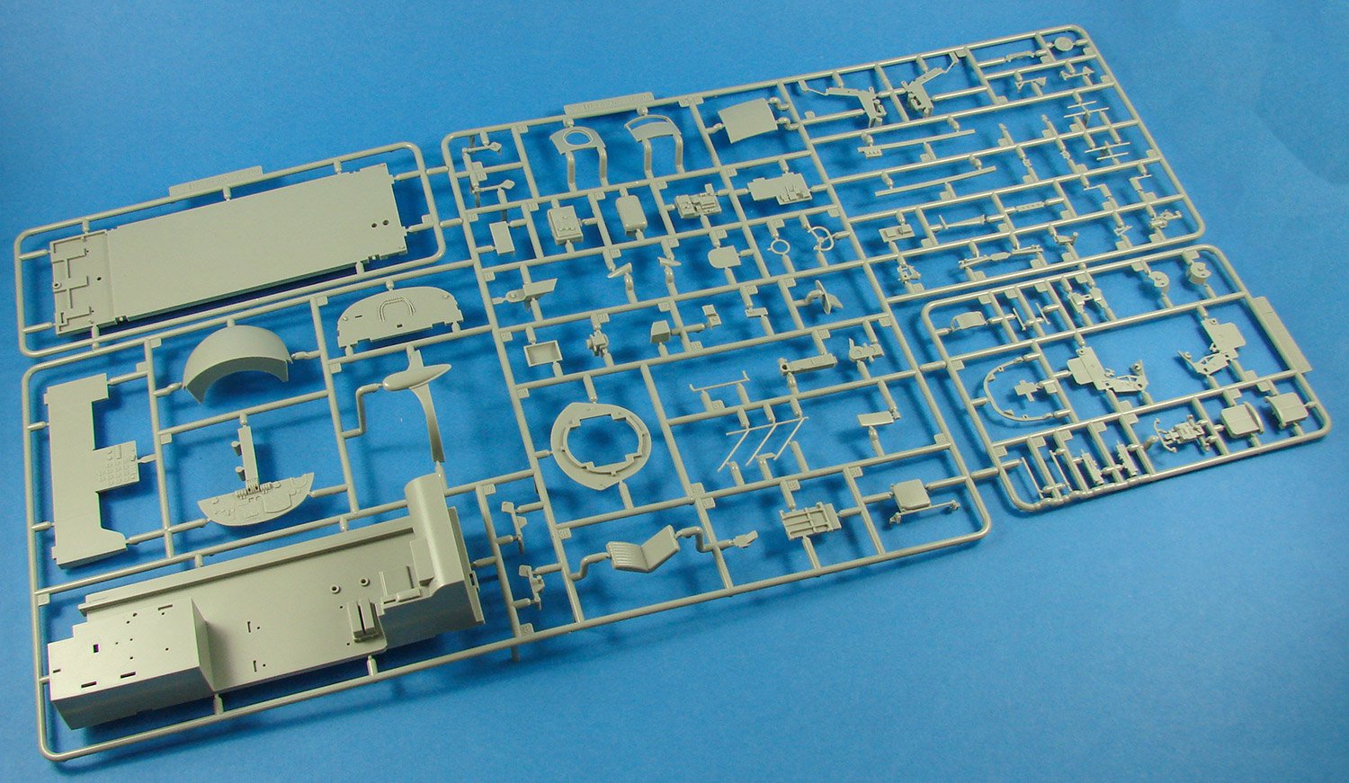
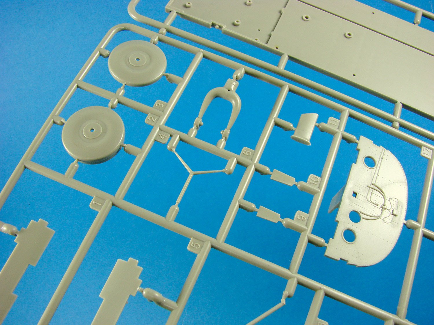
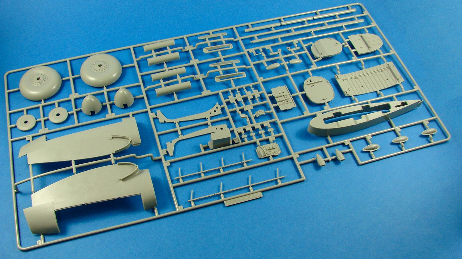
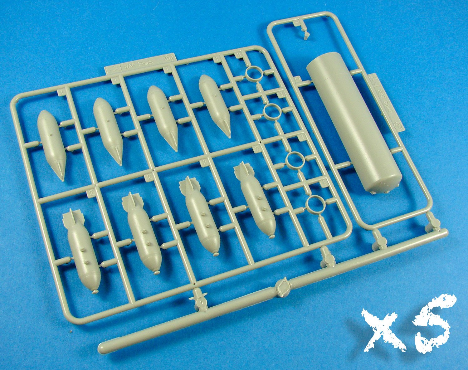
Sprue D
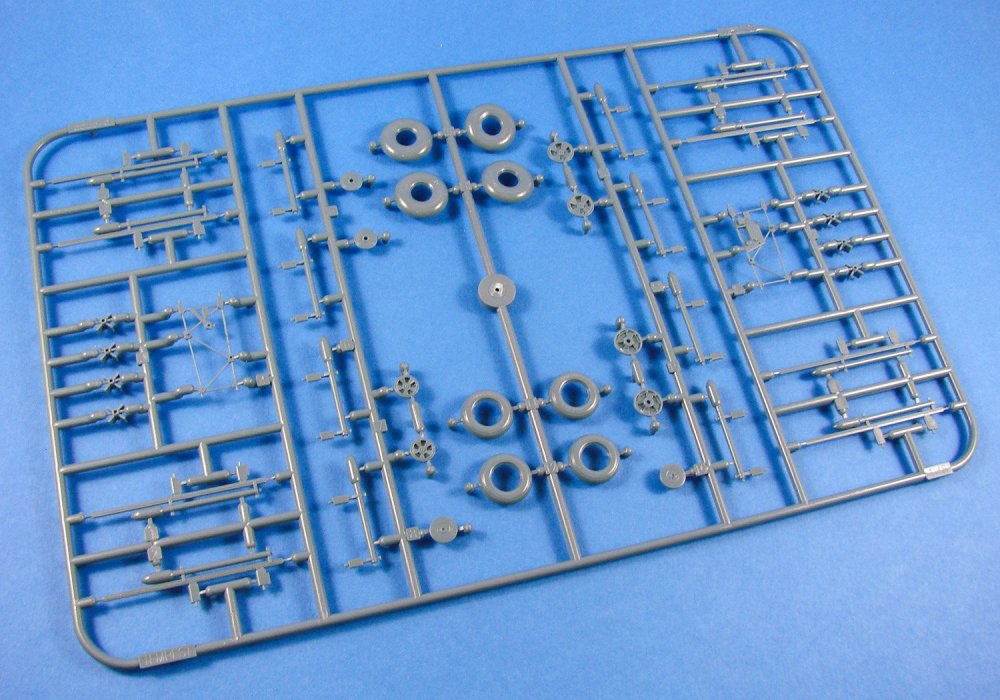
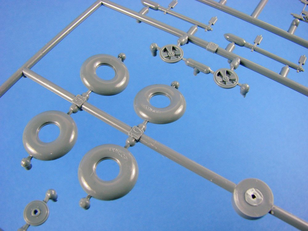
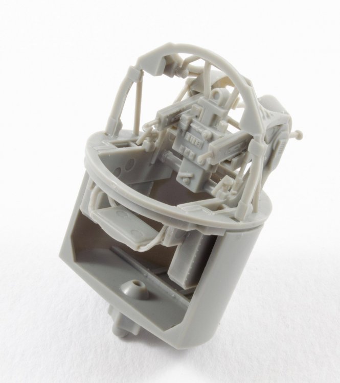
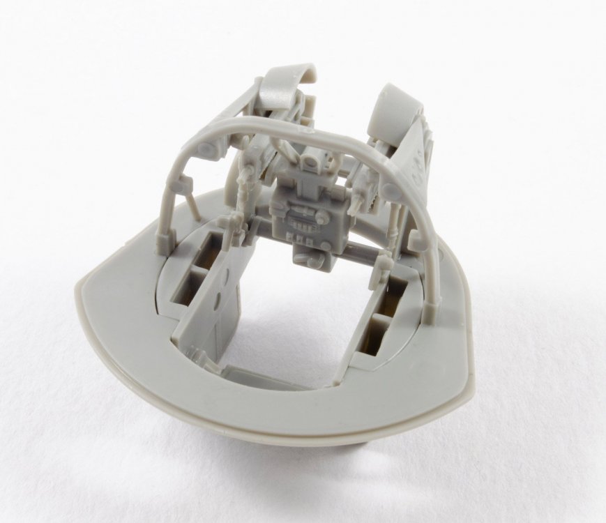
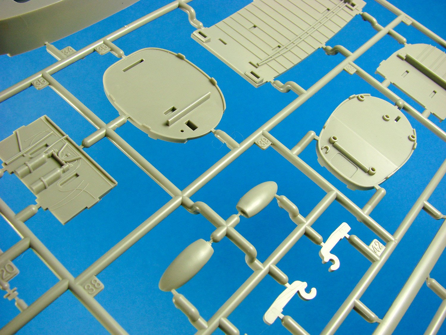
Look at all those parts! Rockets, two styles of when and different spoked hubs…WAIT! There is actually very little you will use on this sprue for this initial release, and certainly notthose rockets! The only parts that you will use here are the balloon-style tyres with the four and five spoke hub options, a tailwheel, and the two frame cockpit tub sides. Those frames are pretty fragile, so care needs to be exercised when removing them from the sprues. These frames contain the basic panels upon which you will add the consoles, trim wheel, throttle quadrant etc. Optional decals are supplied for some of the console detail etc.
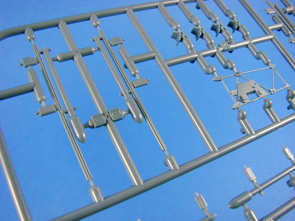
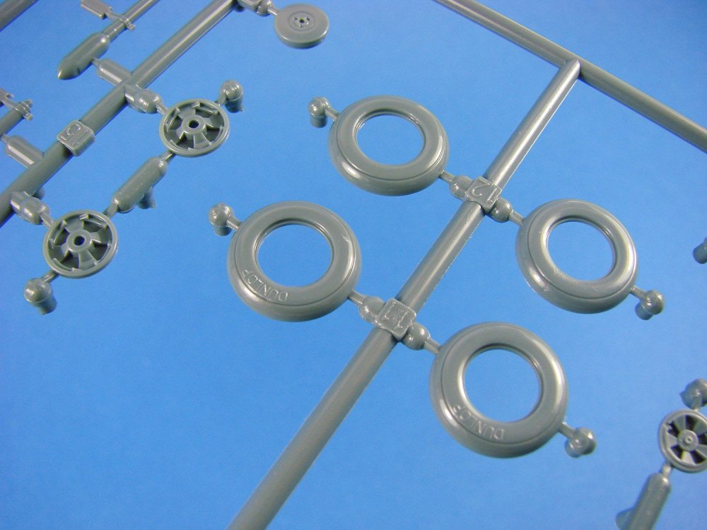
Eduard has supplied the wheels as halves and with separate hub details. The wheels themselves aren’t weighted, and you may wish to use their resin alternatives, although these can be made to look very nice, and then also have the DUNLOP name emblazoned on them.

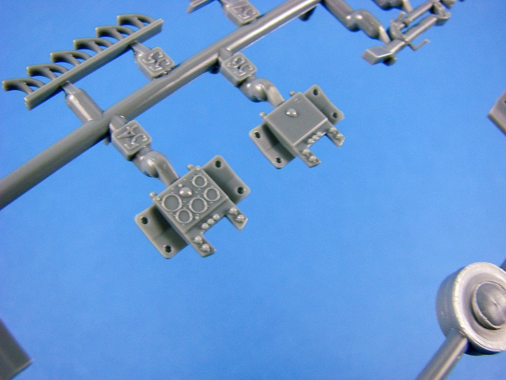
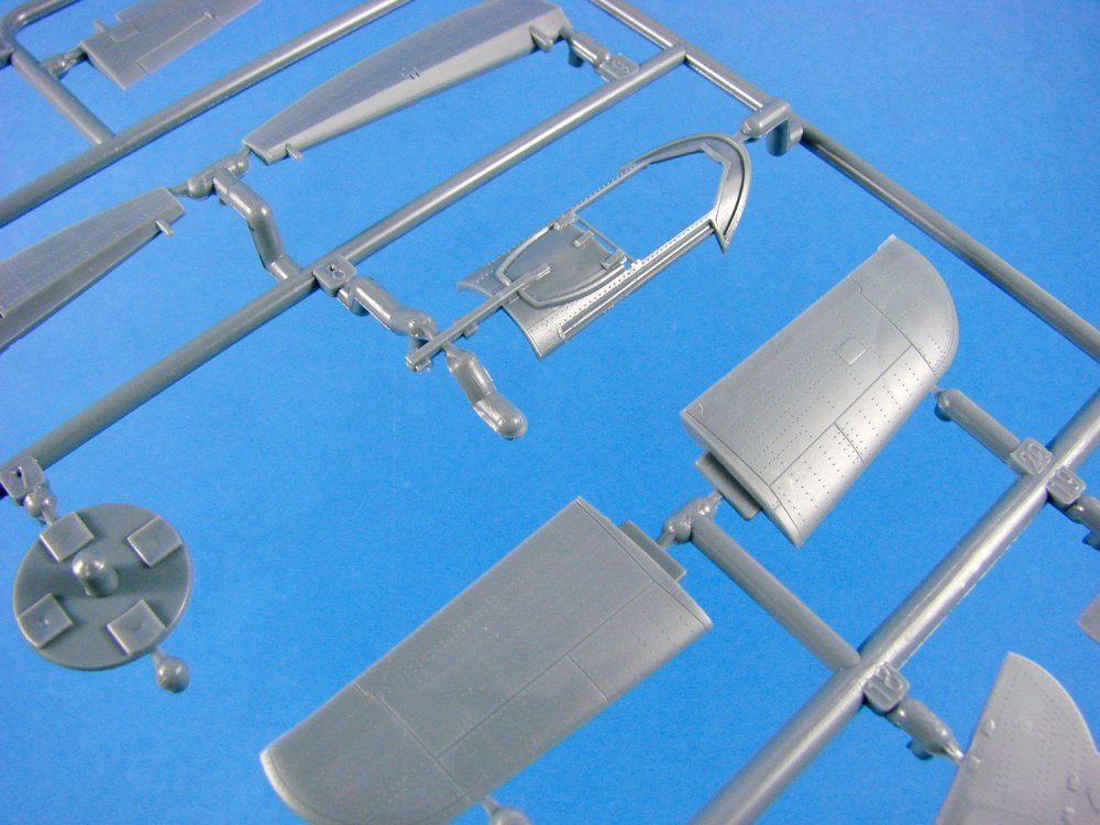
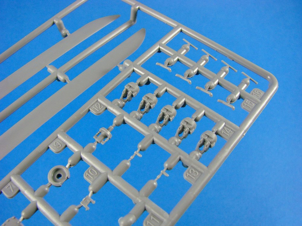
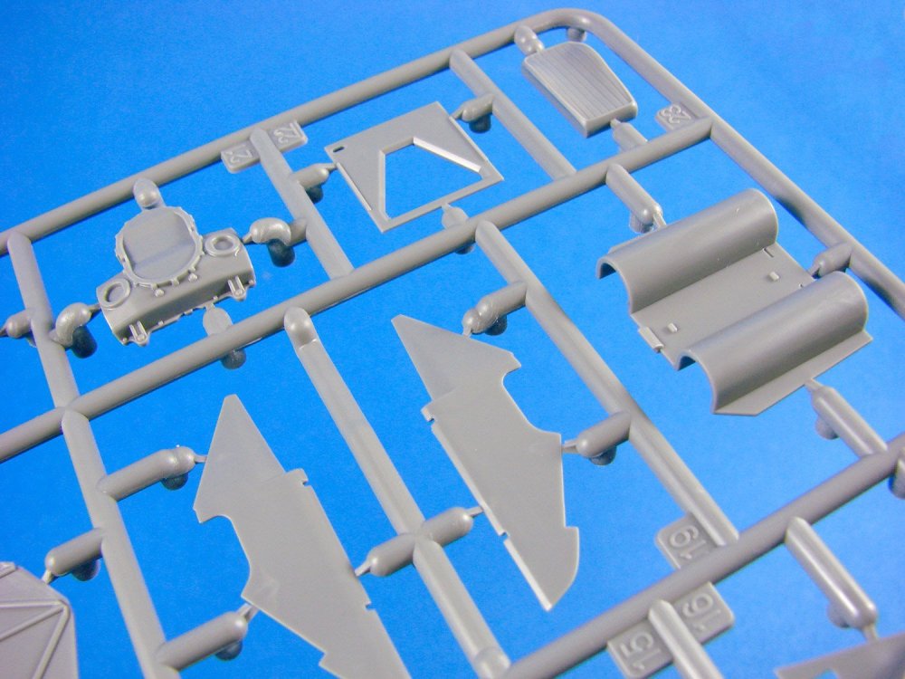
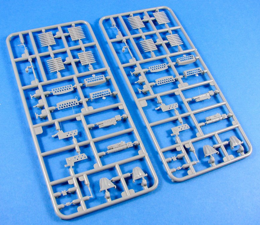
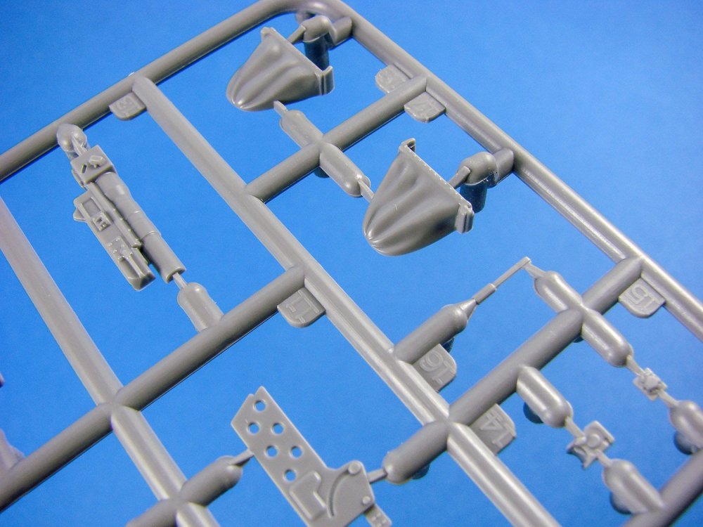
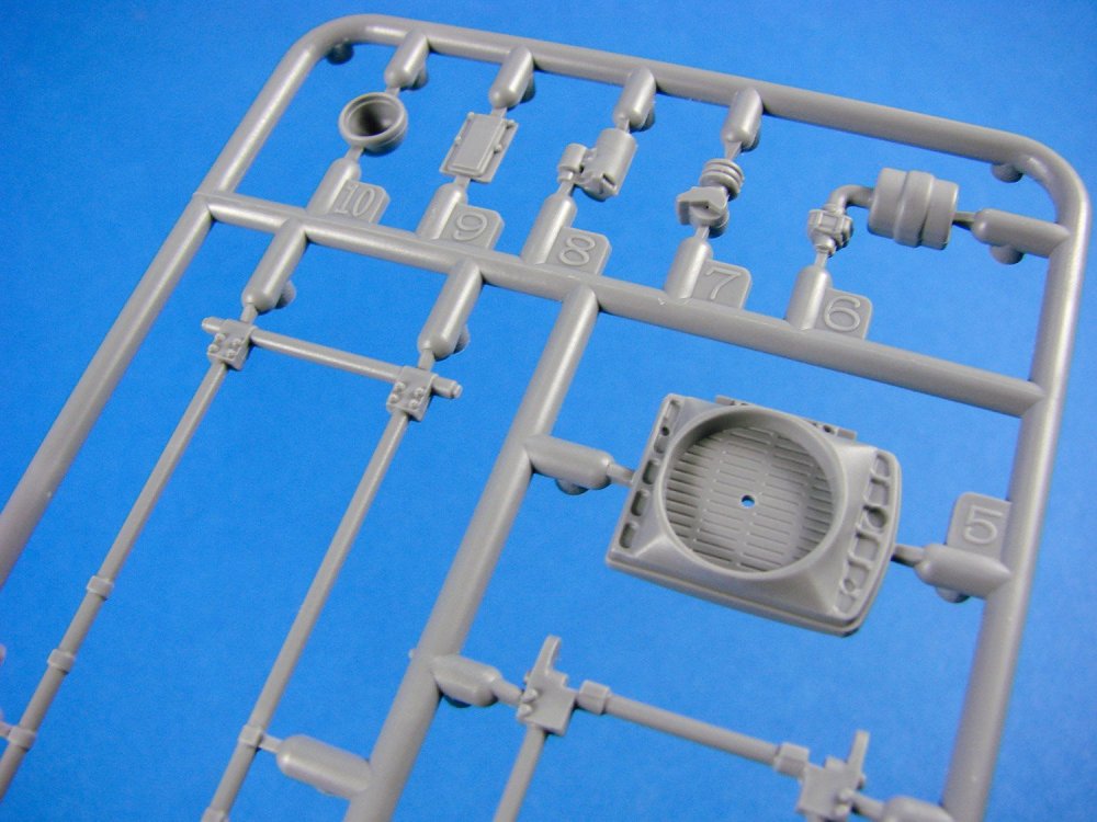
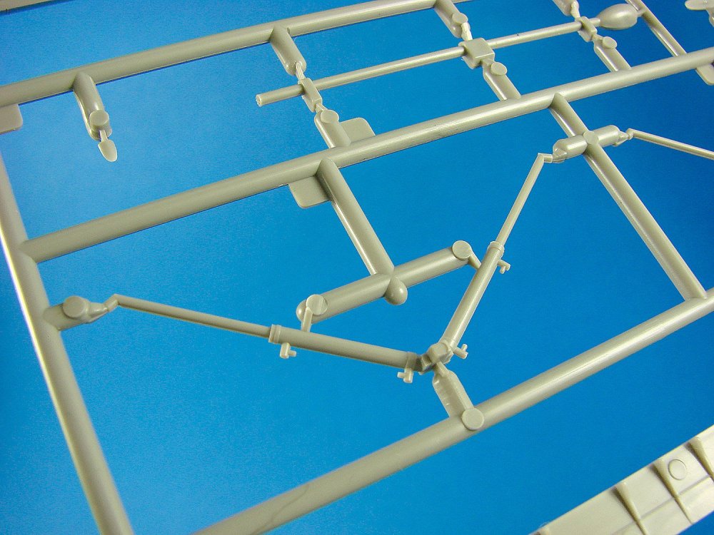
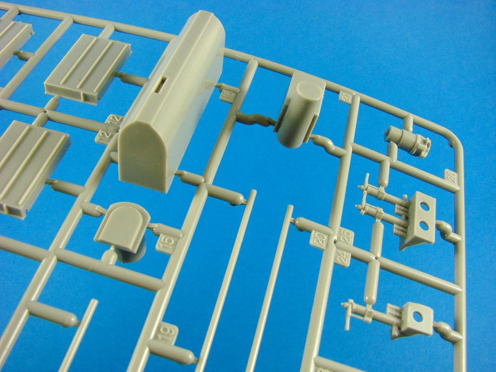
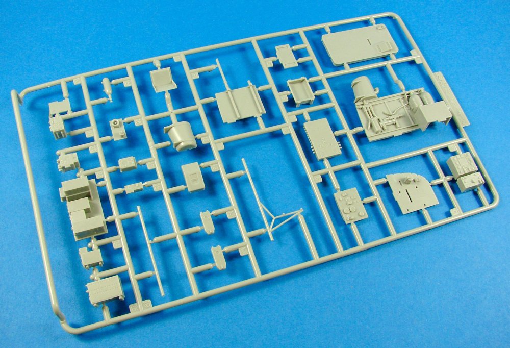
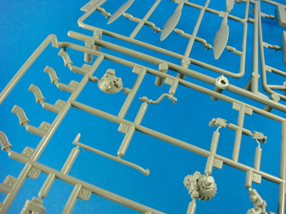
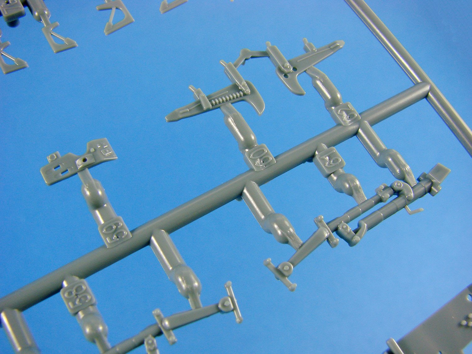
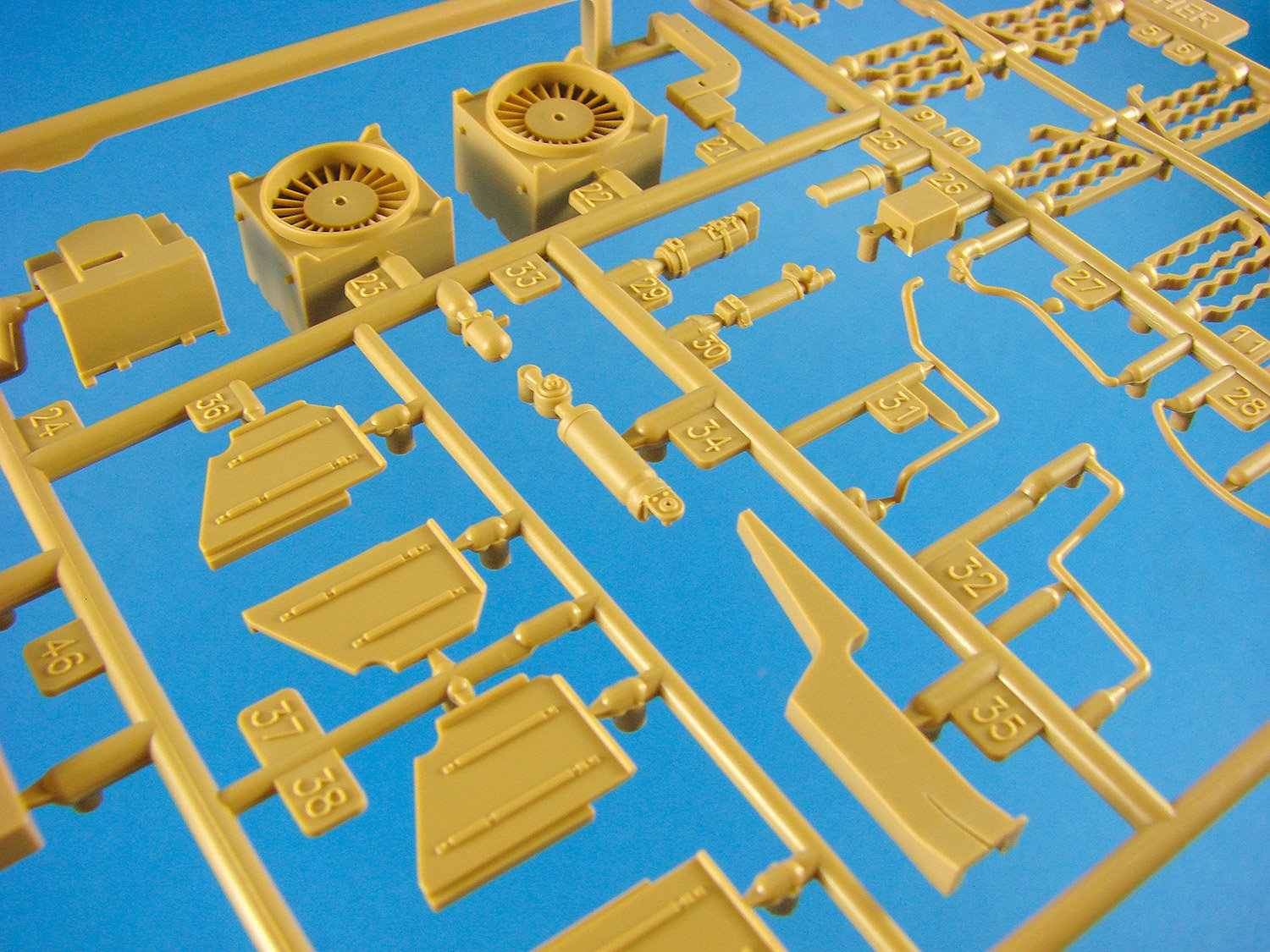
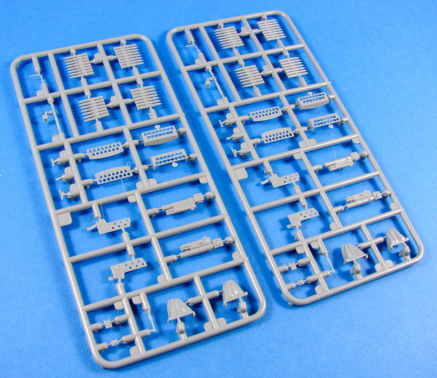
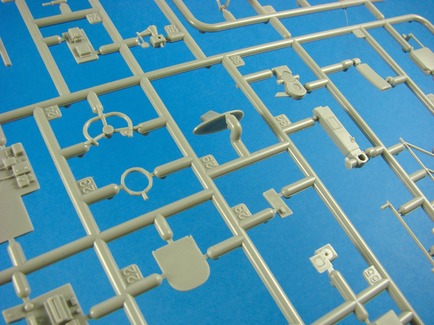
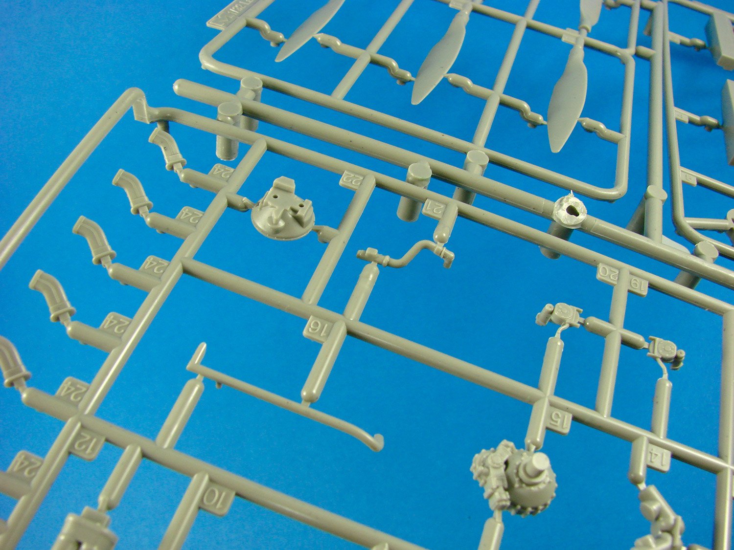
Sprue E
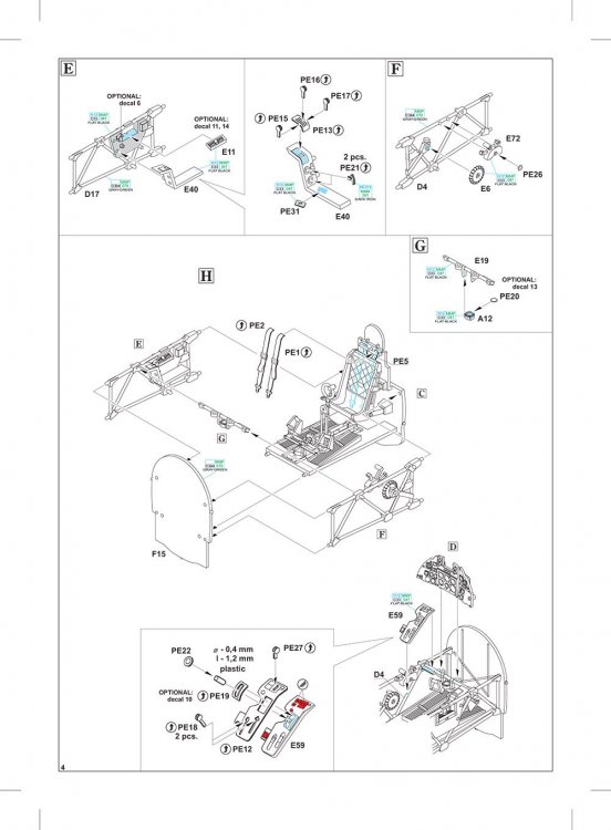
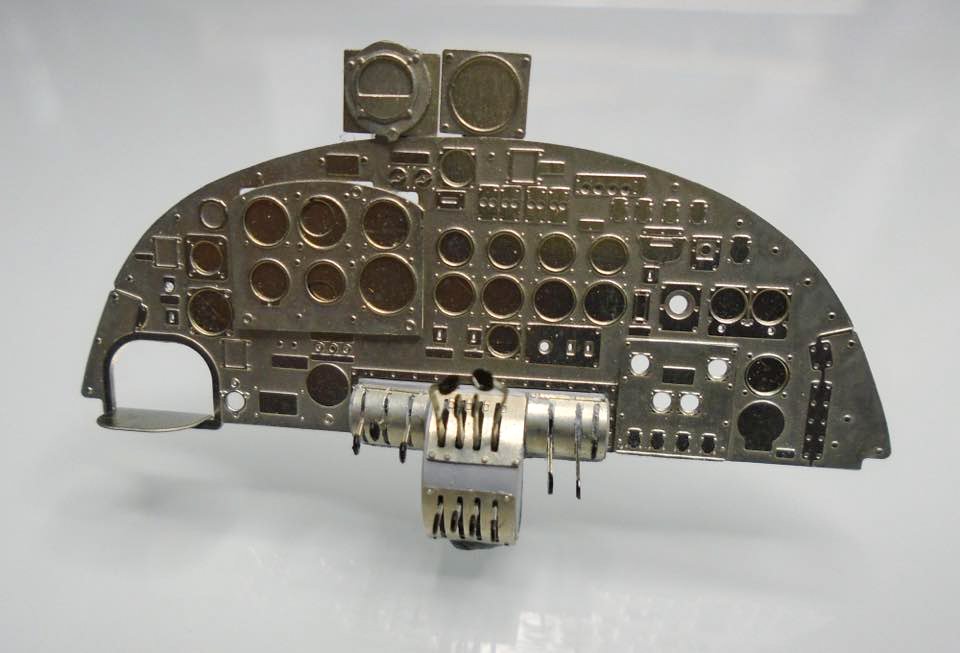
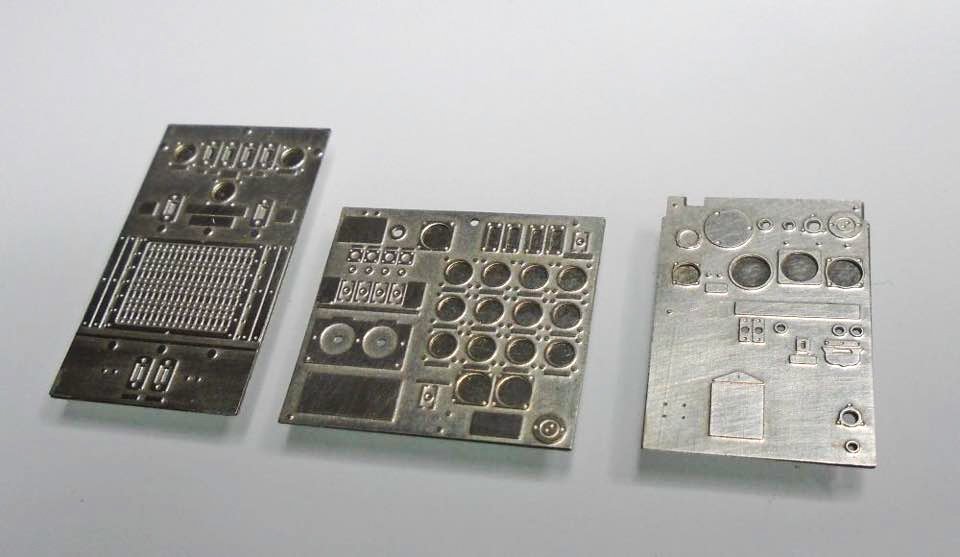
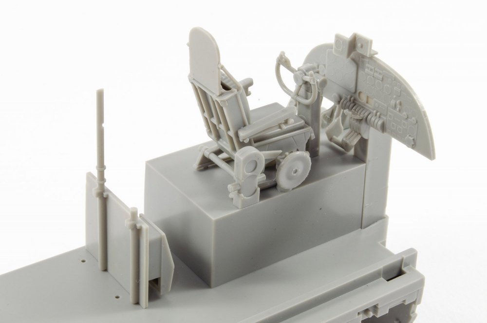
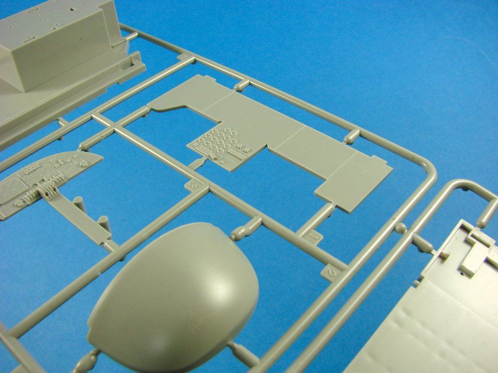
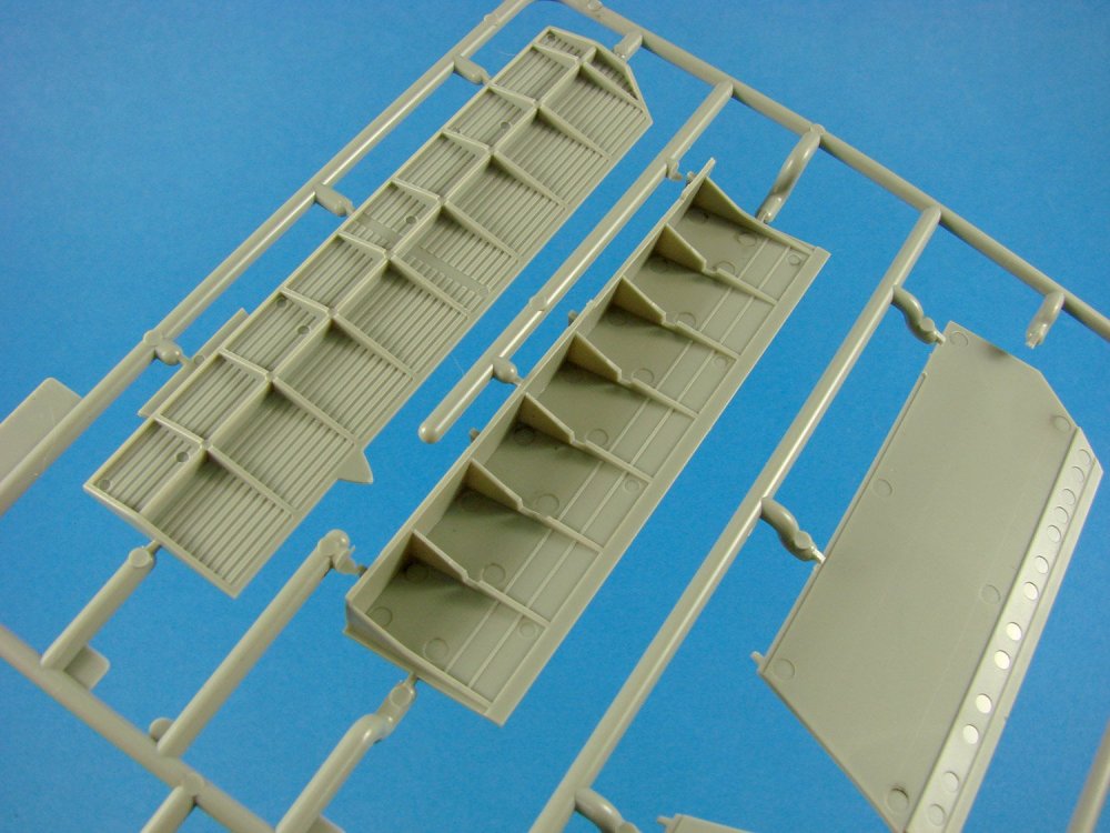
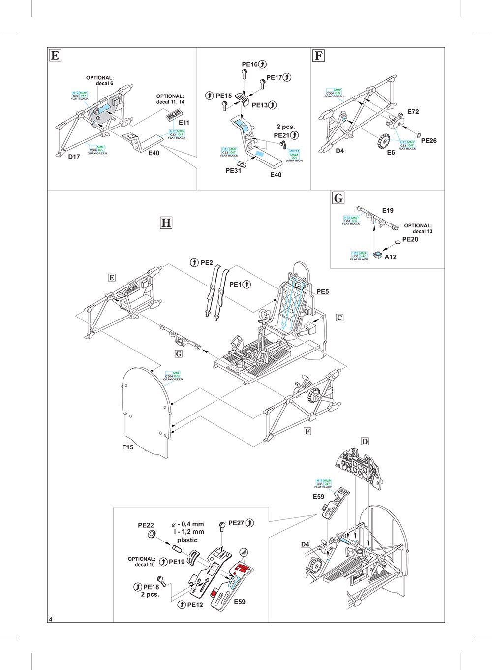
Many of the Tempest’s cockpit parts are to be found here, such as the floor with integral foot boards, rudder bar and separate pedals (PE alternatives are supplied for the latter), control yoke with spade grip, three-part seat with quilted back rest, consoles, etc. There are actually THREE instrument panel options provided. One of them is for a three-piece plastic item with gauge details into which you can add instrument decals. Another option is also for a three-part unit, but with blank faces upon which you can use full decals. The last option is contains a single piece central unit onto which the various colour PE parts can be installed. As this is a ProfiPACK, I assume most will make use of the latter option.
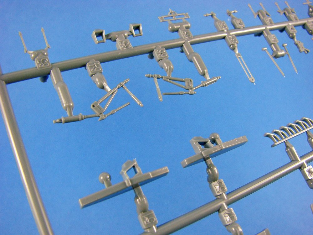

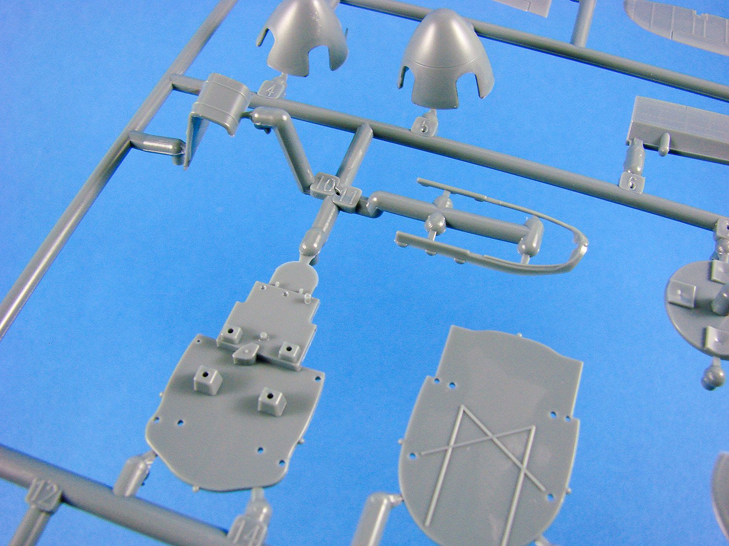
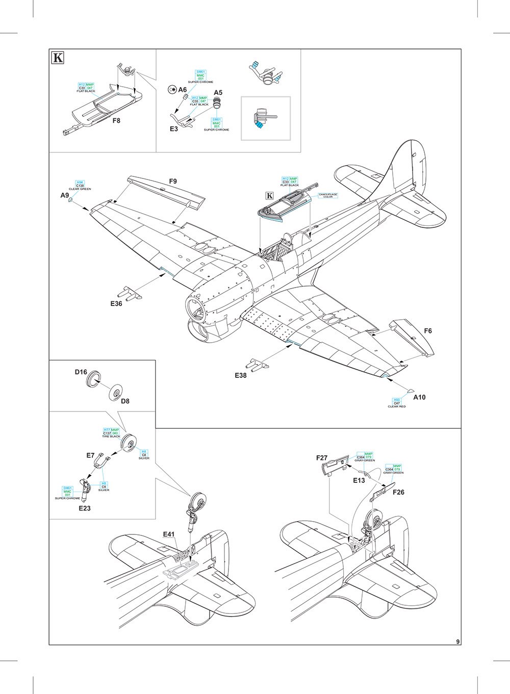
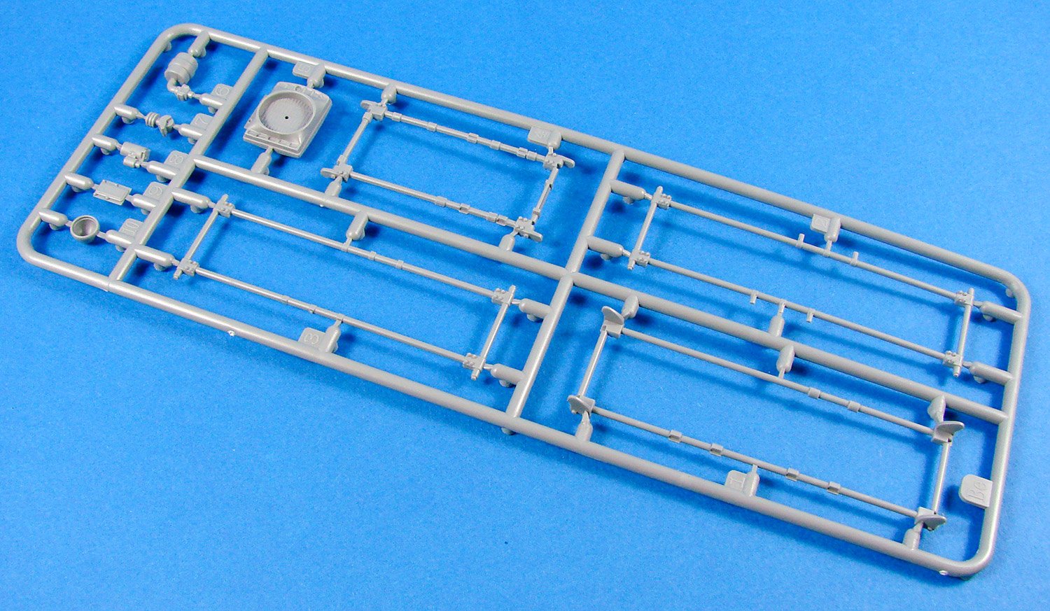
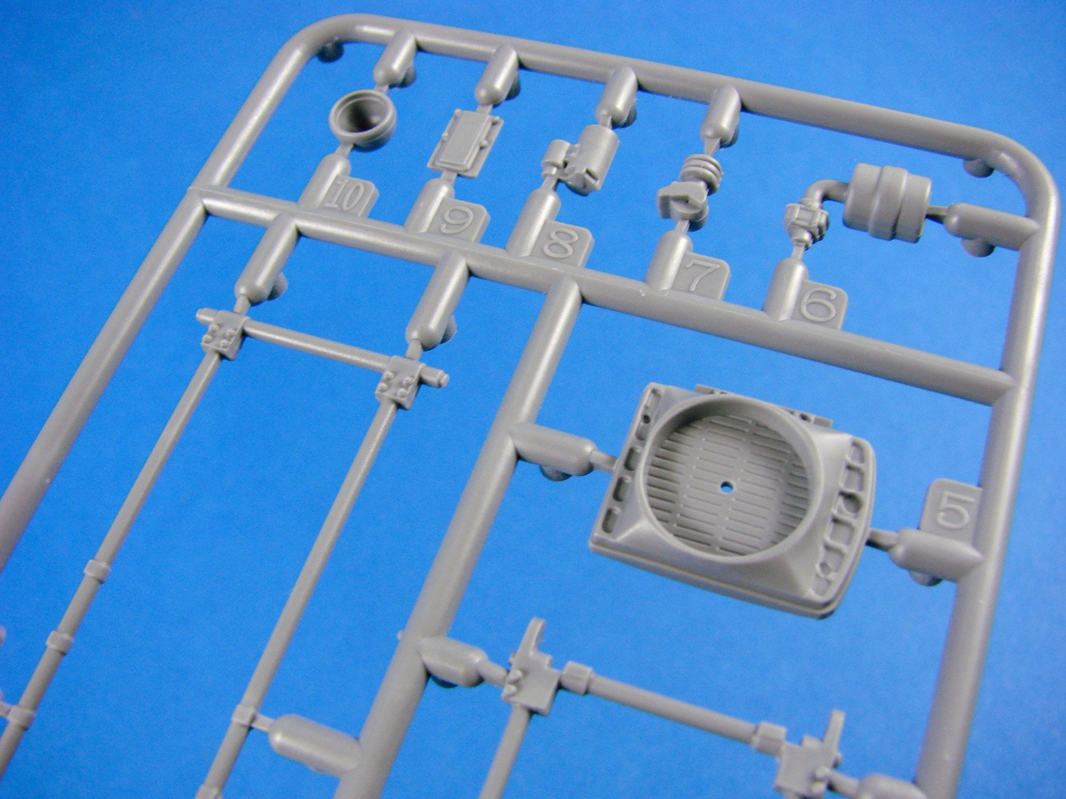
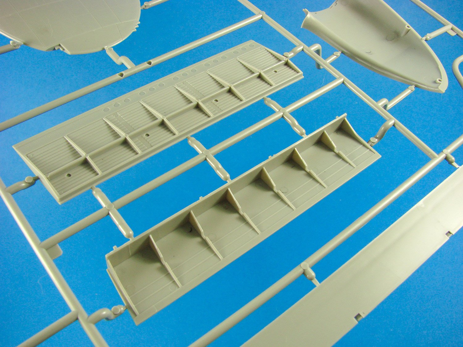
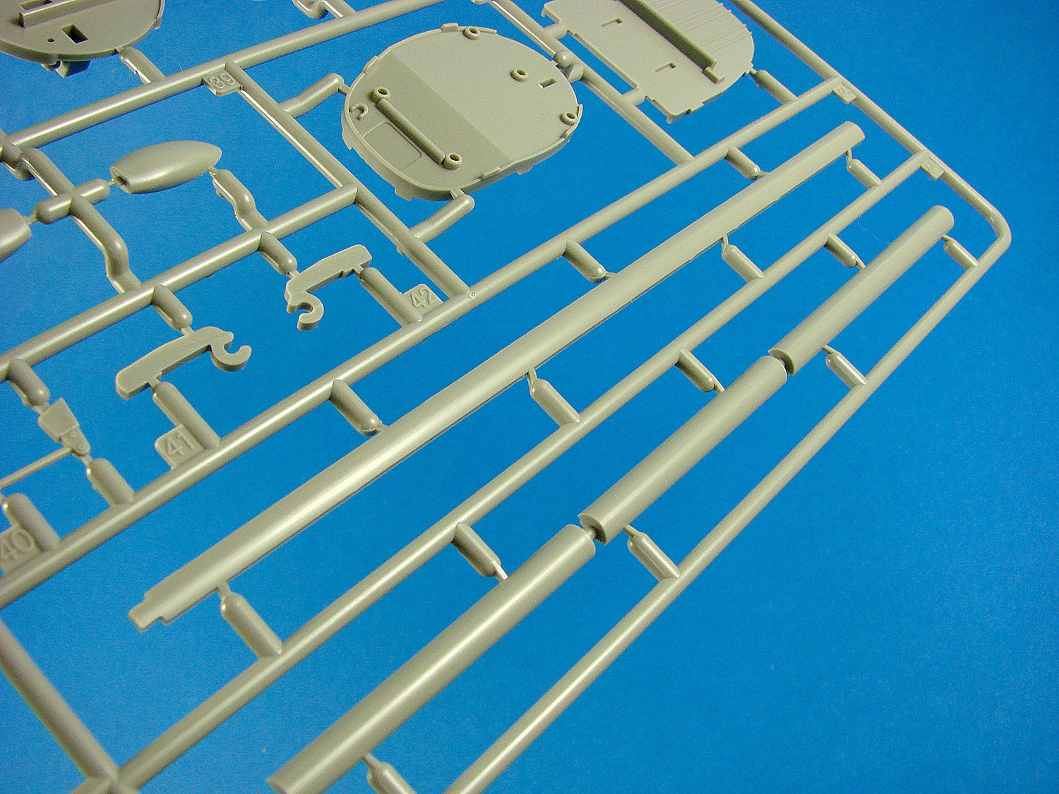
You will also find the undercarriage struts here, with some superb linkage details, as well as the retract mechanism with their hydraulics cylinders.
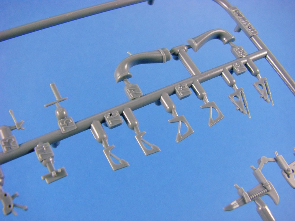
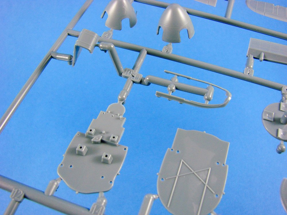
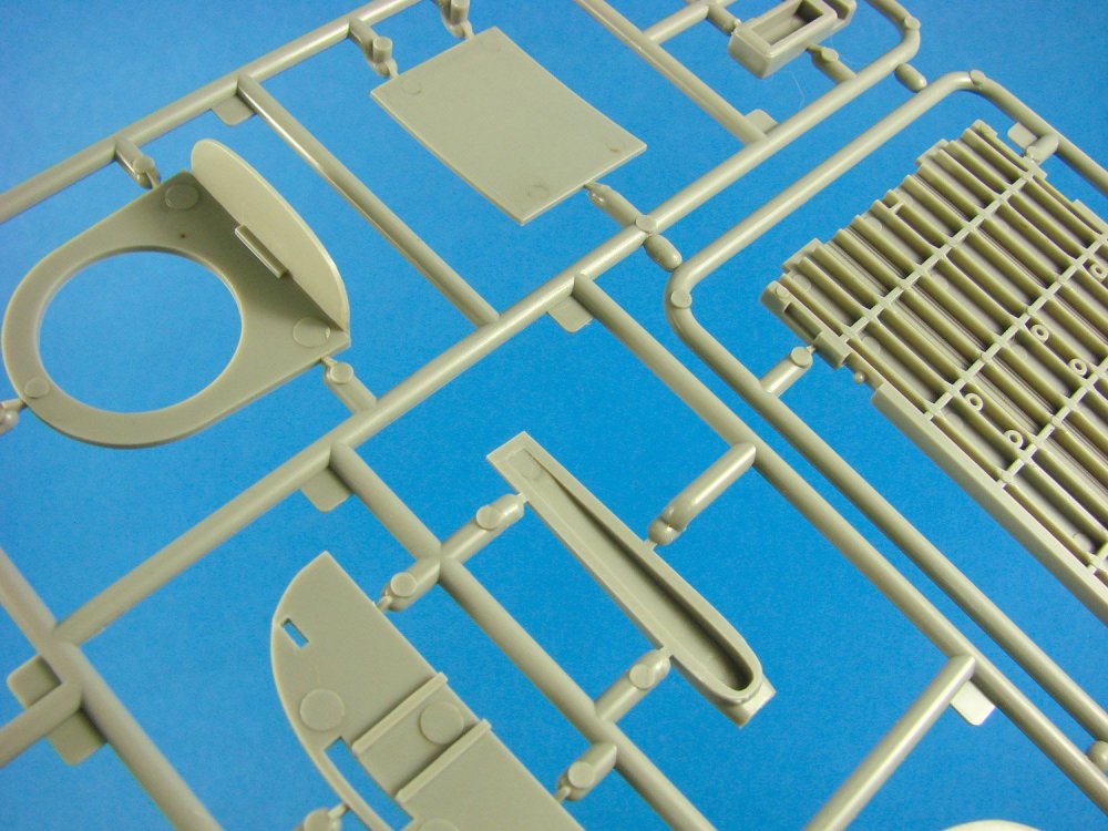
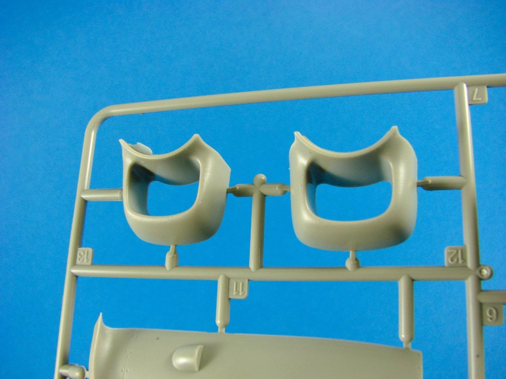
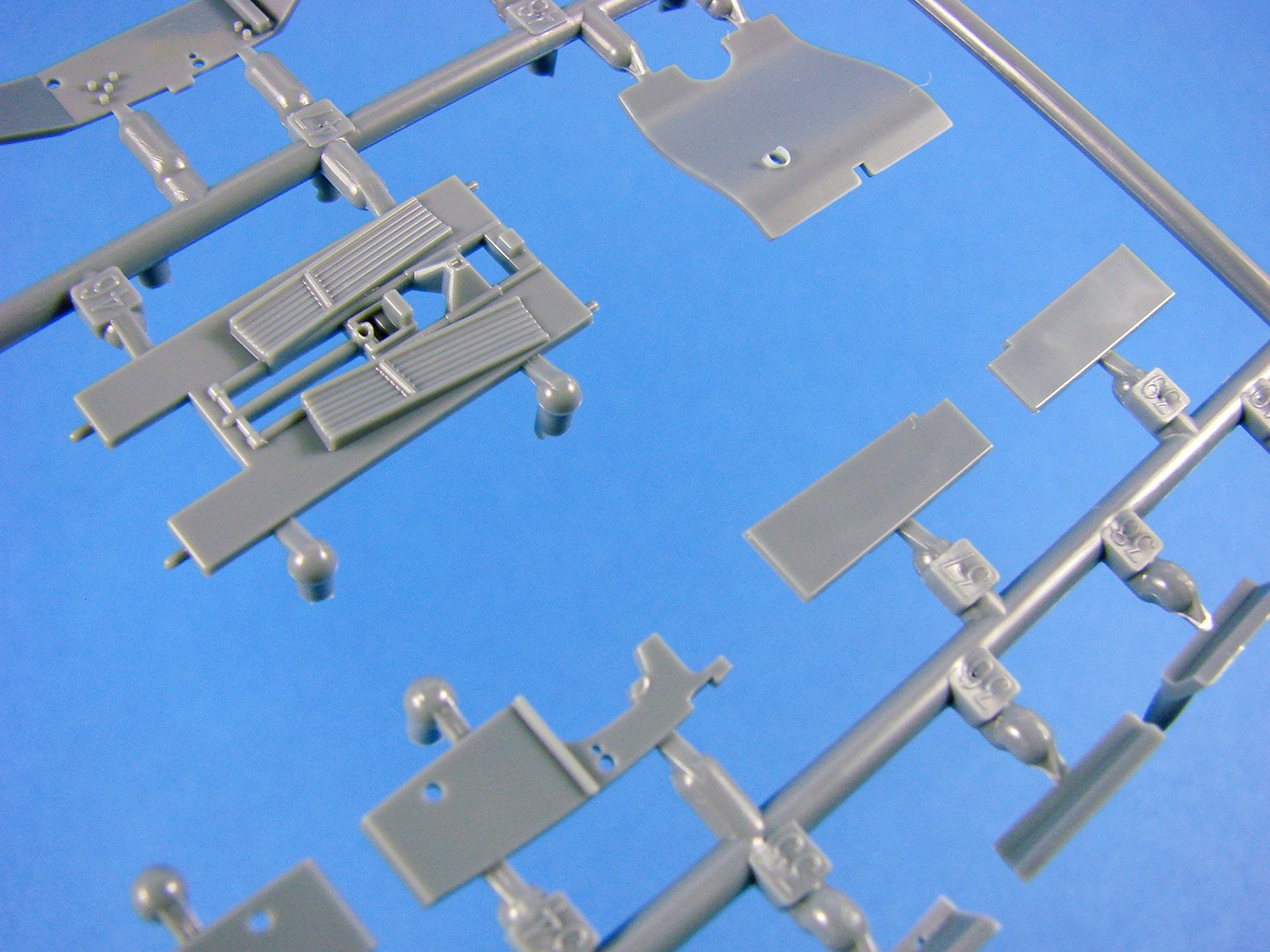
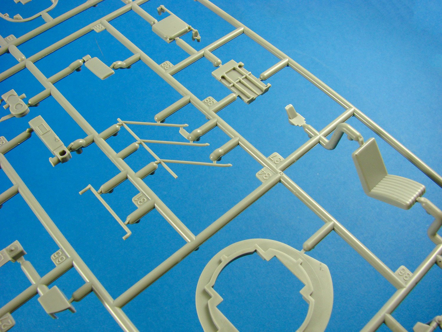
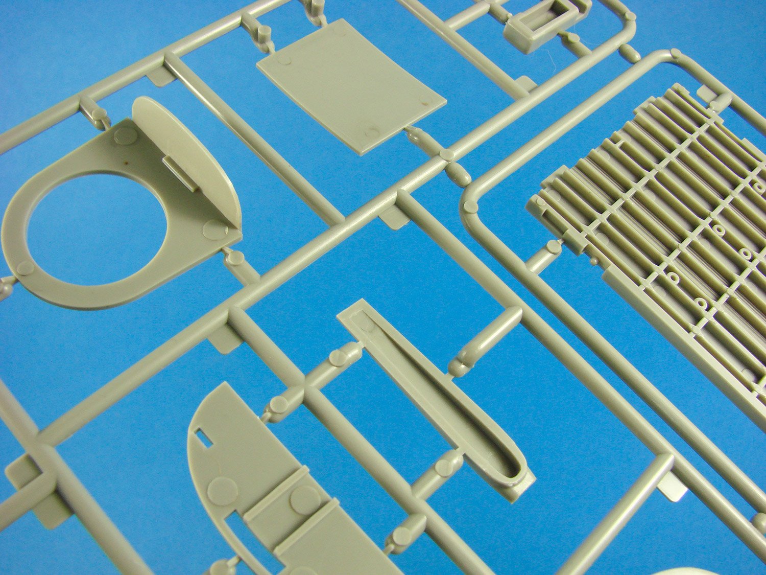
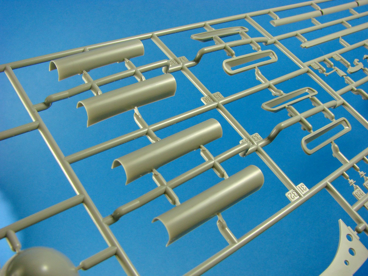
Eduard has broken down the intake unit into seven parts, all to be found on this sprue, including the large chin radiator unit, with its fine grille details.

Other parts on this sprue include the main gear well walls and rib details, tail wheel bay unit and strut, tailwheel doors and closing mechanism, single-piece leading edge insert with gun barrel fairings and hollow ends, rudder control horn, pitot, main gear retract indicators, and exhaust stubs etc. The latter are nicely moulded but lack any hollow ends, unlike their Brassin option which is will be available soon.
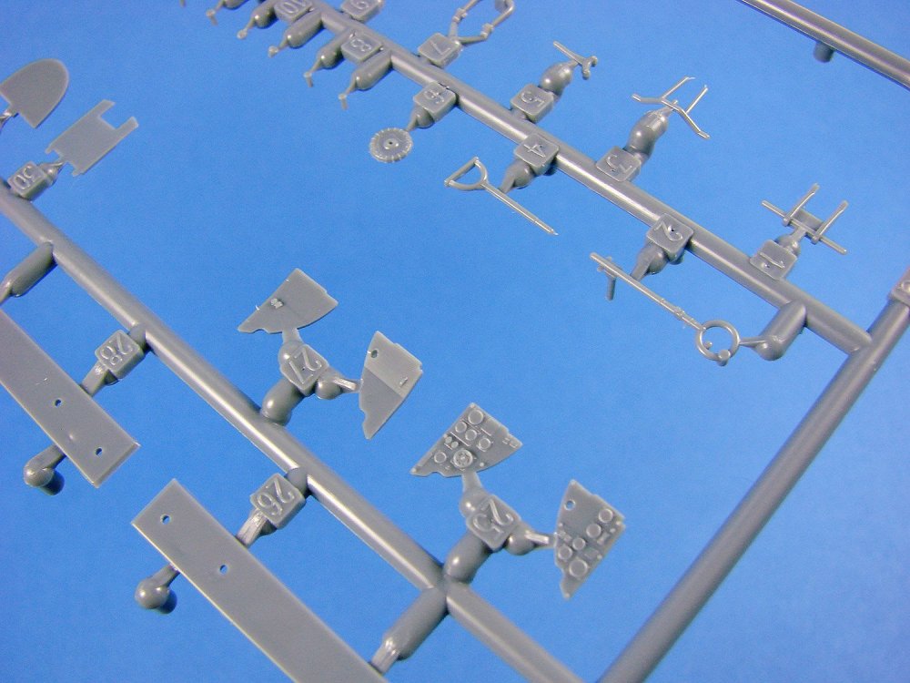
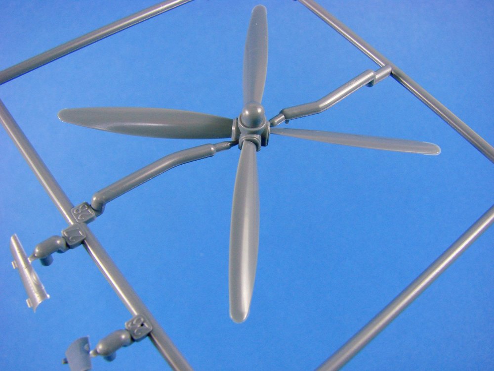
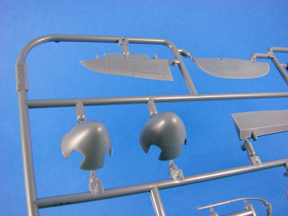
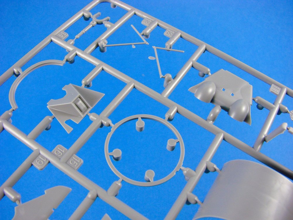
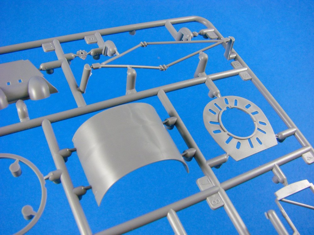
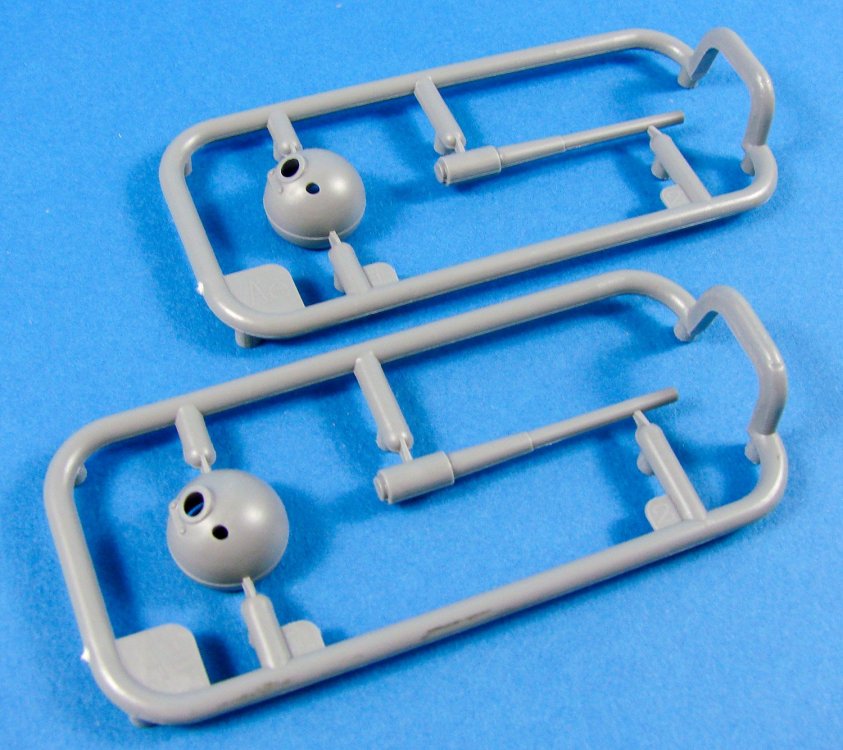
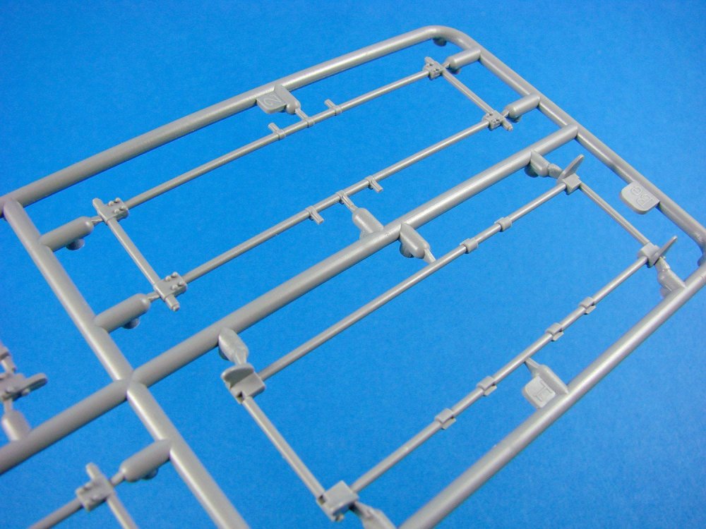
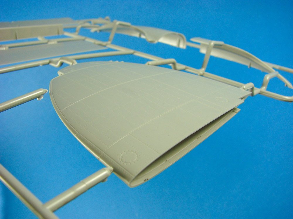
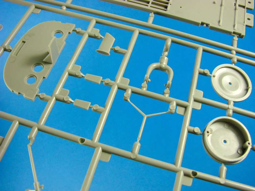
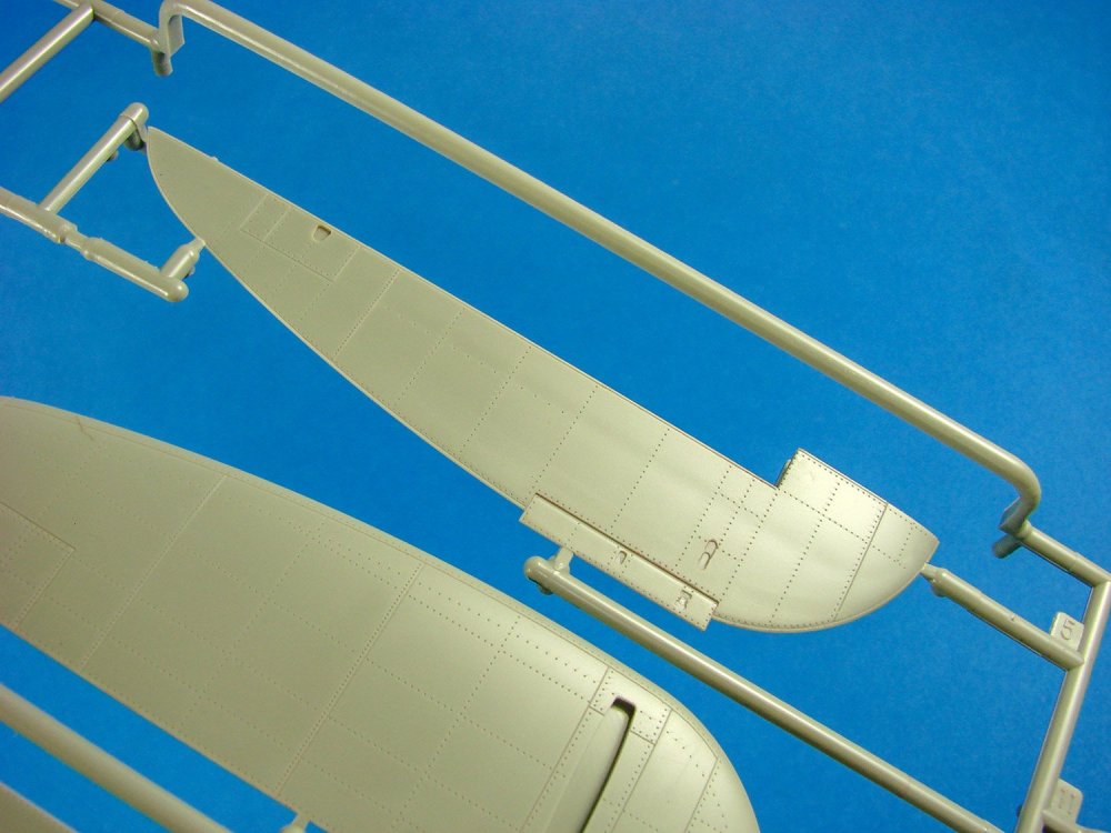
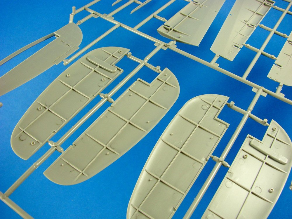
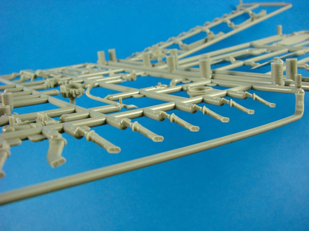
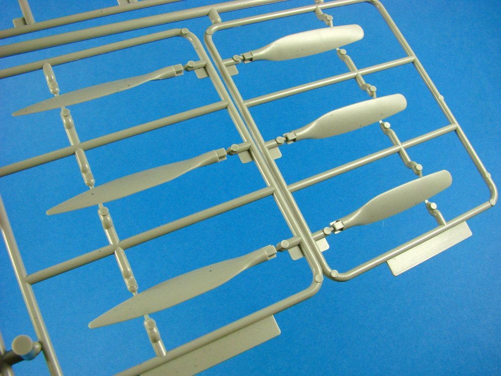
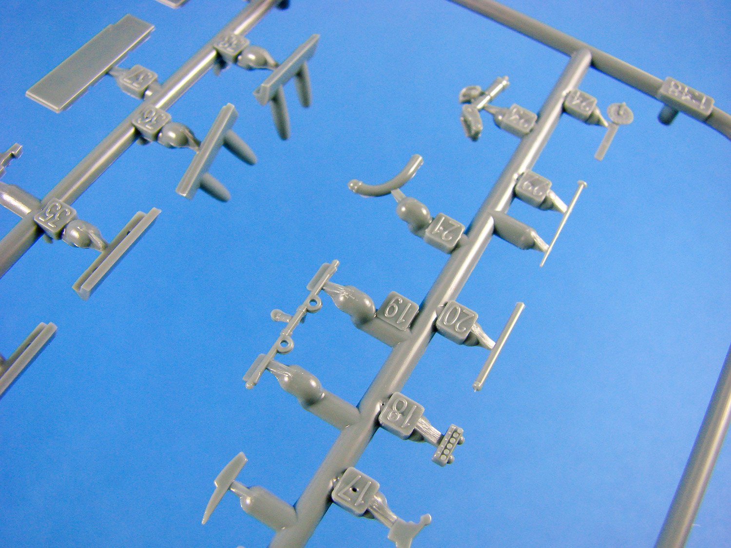
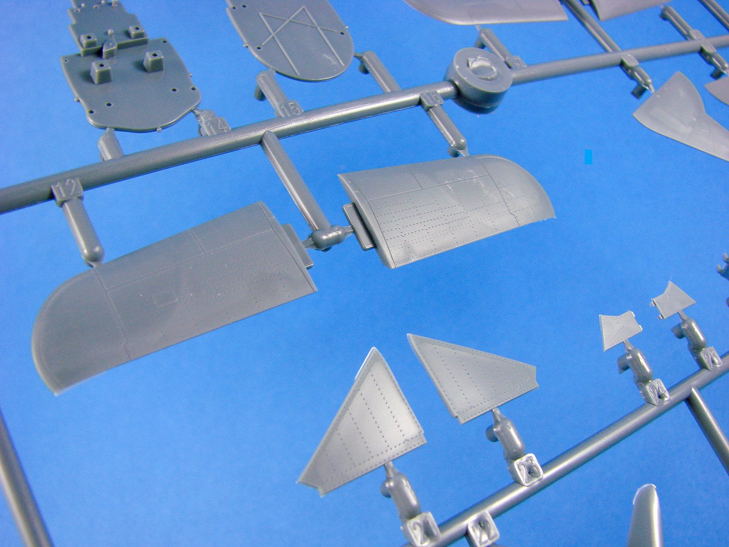
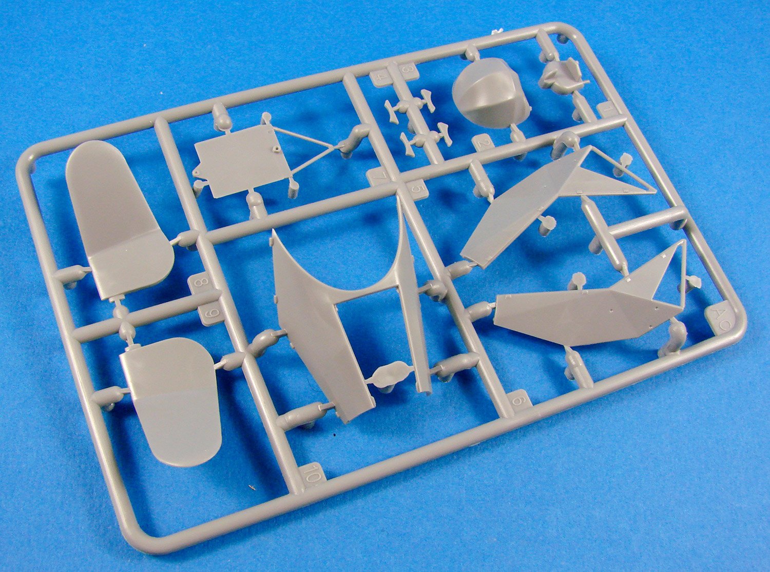
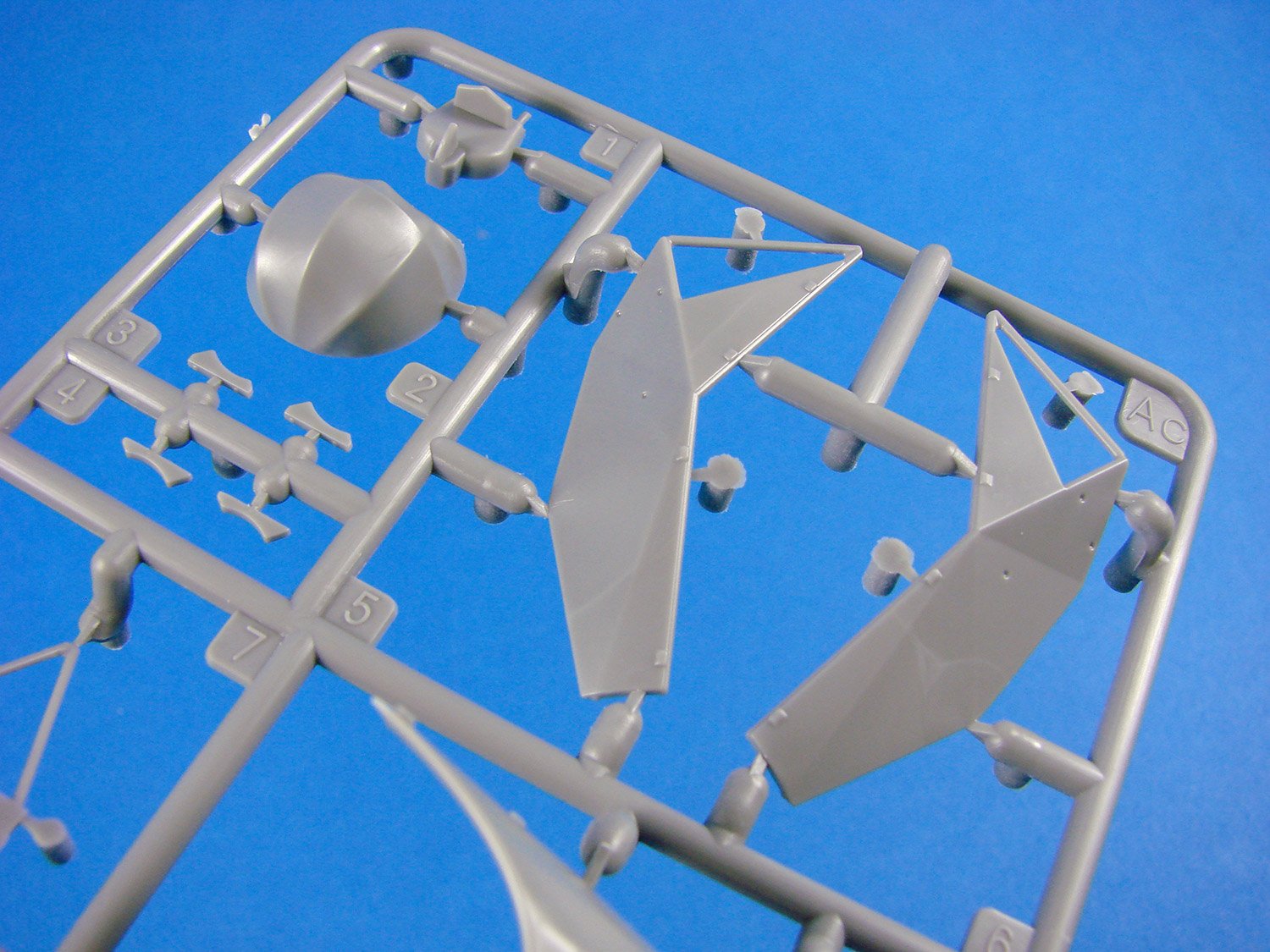
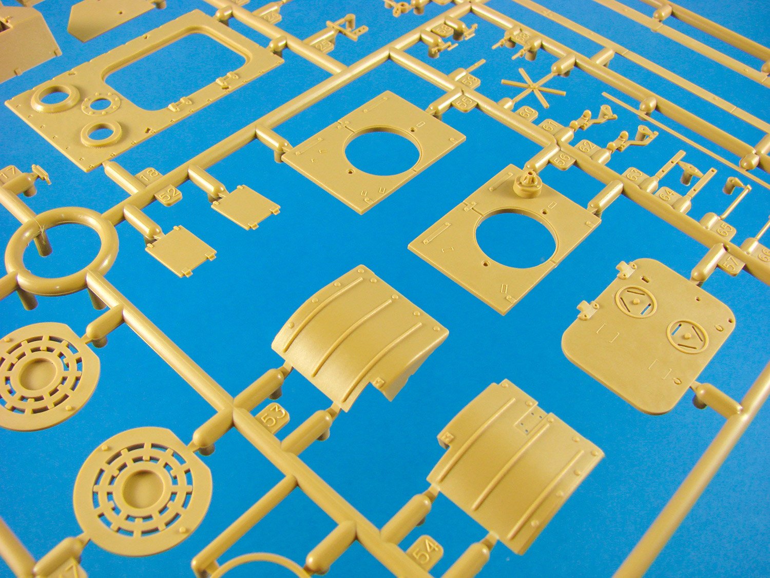
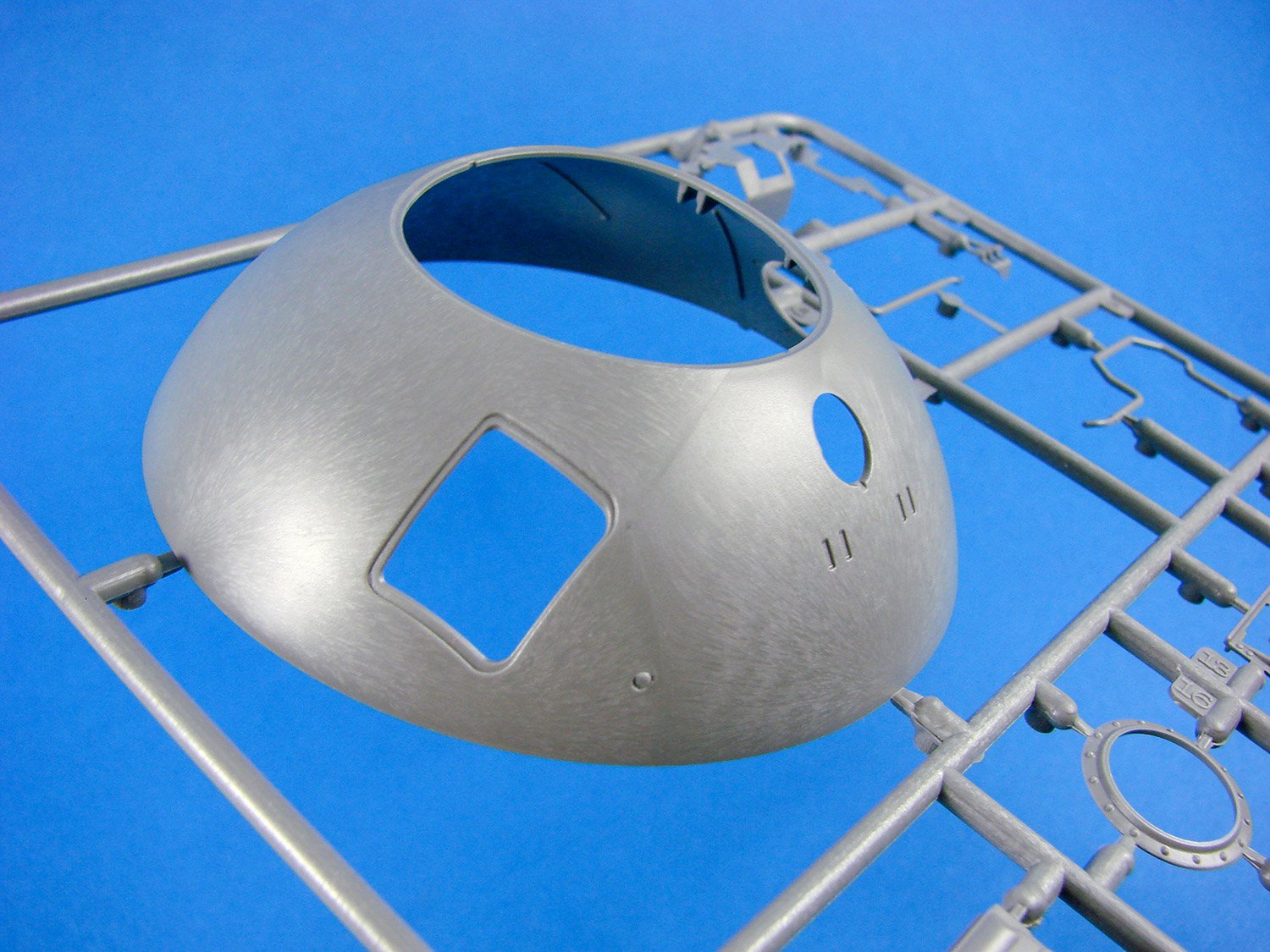
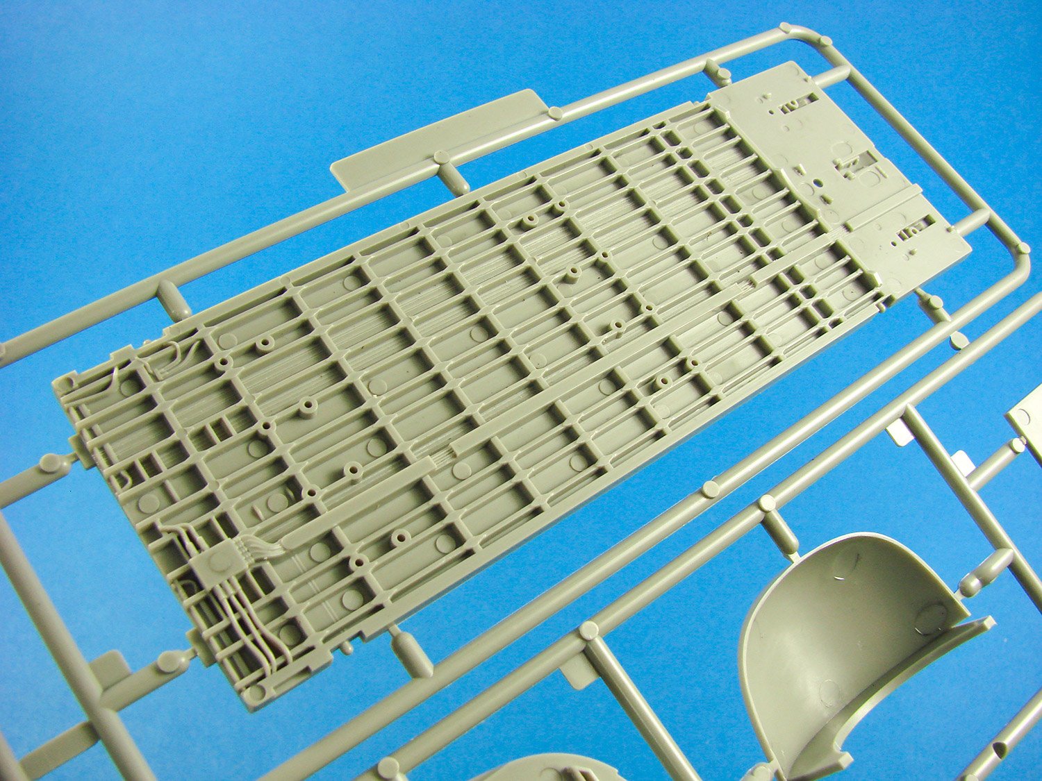
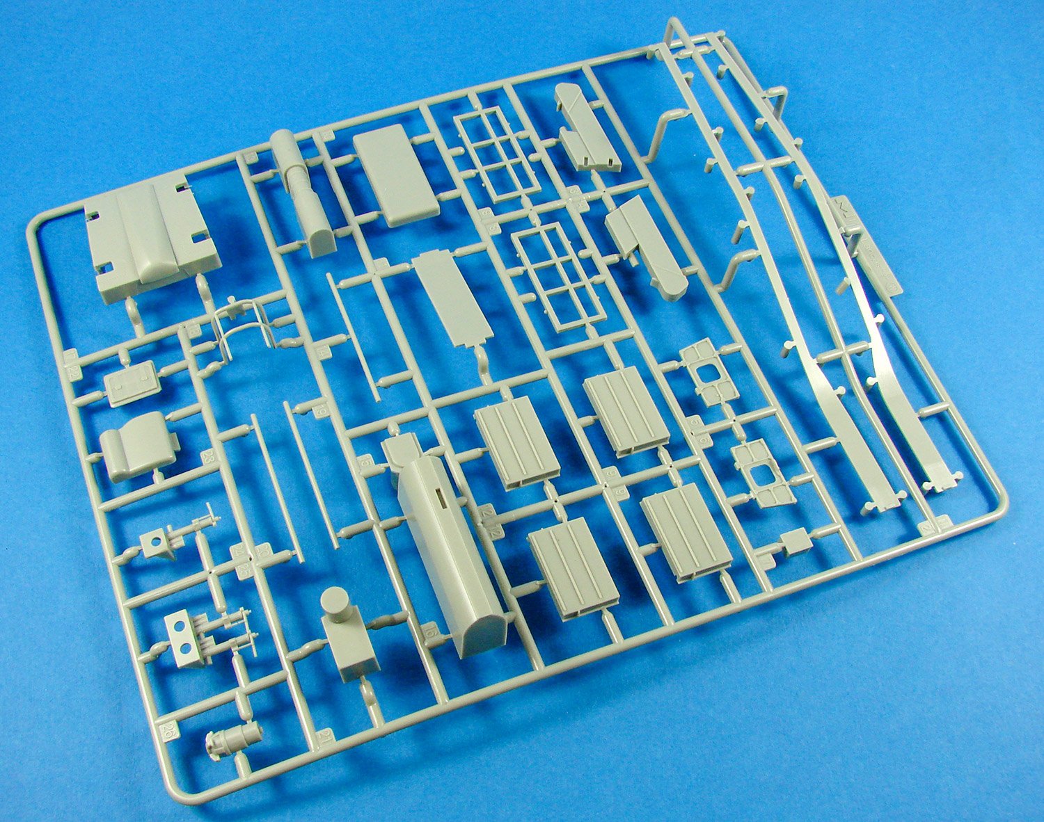
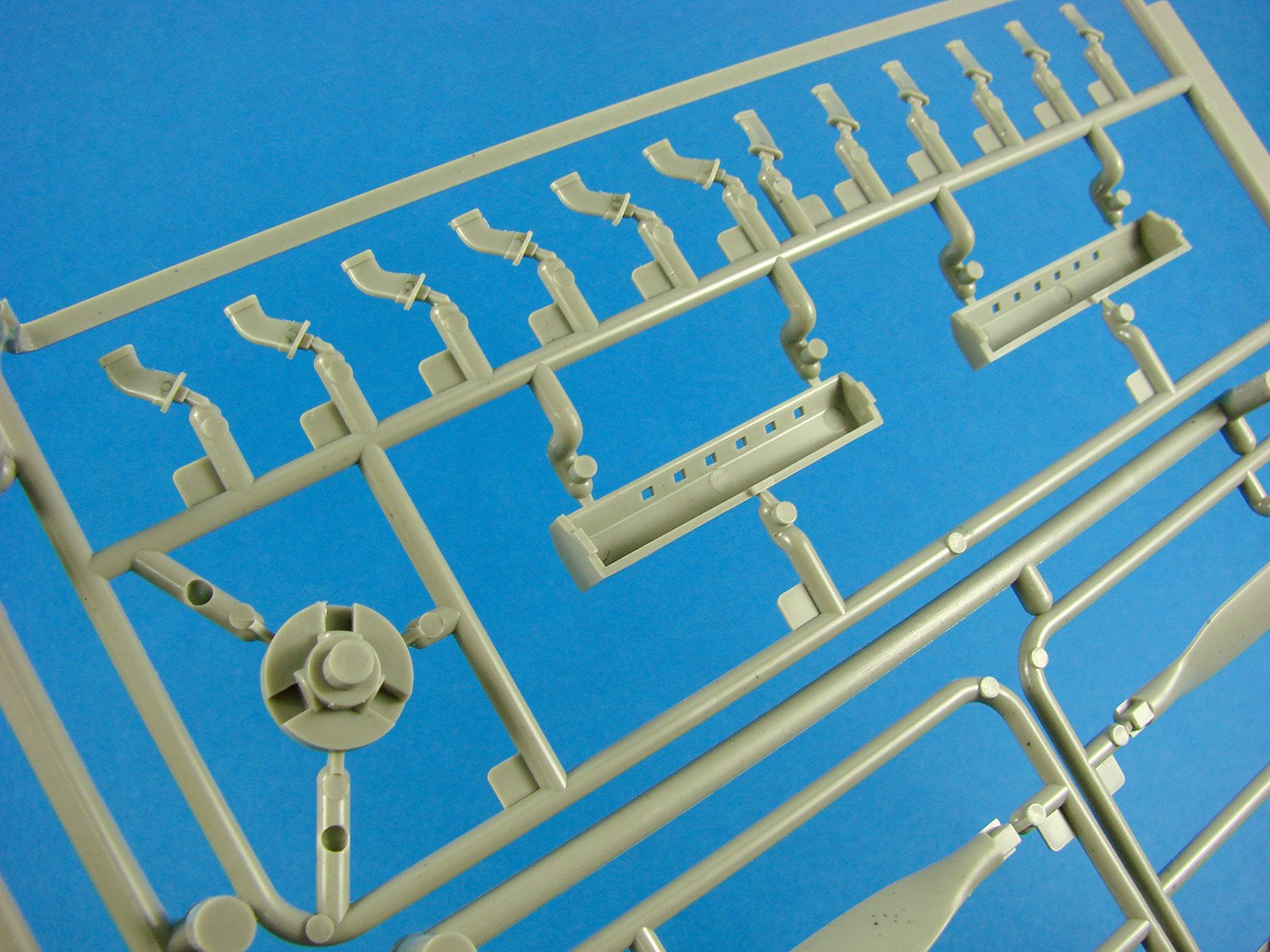
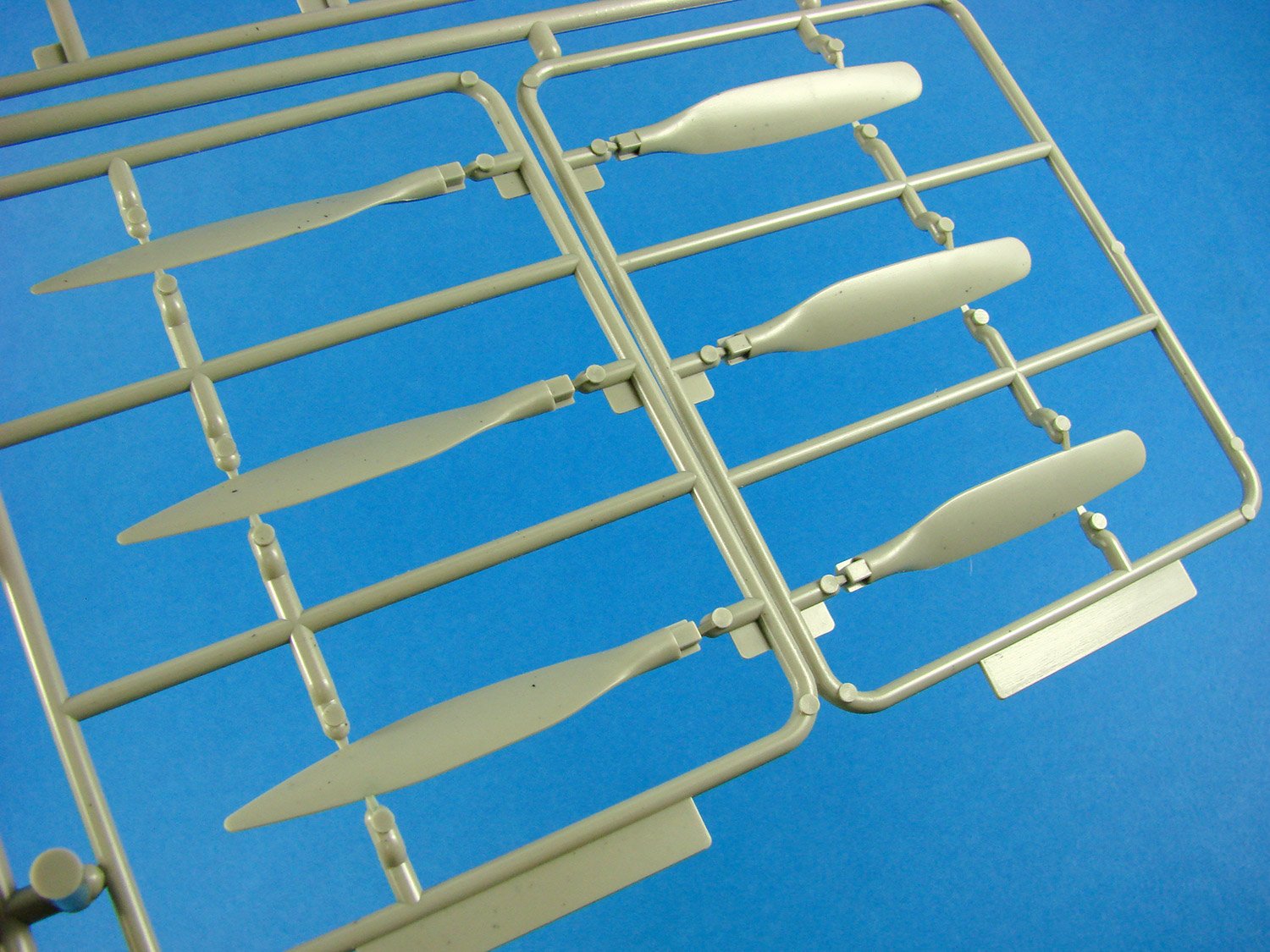
Sprue F
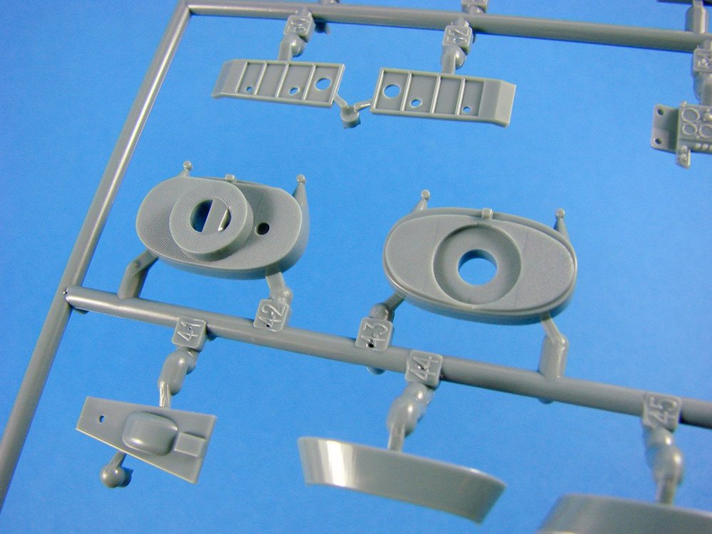
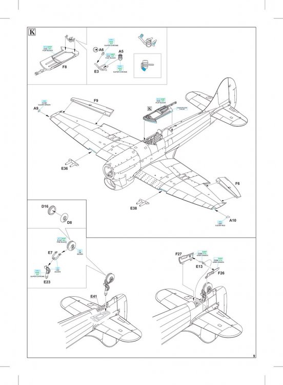
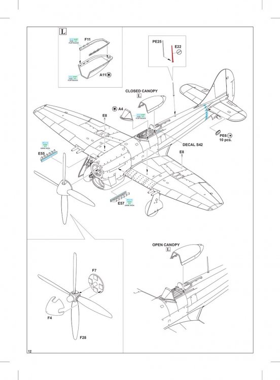
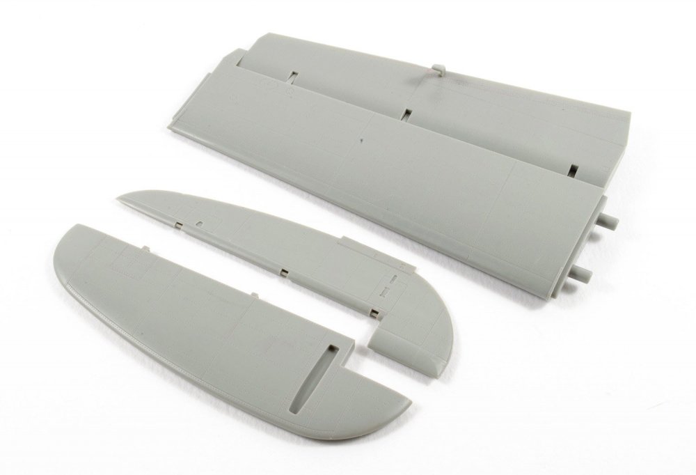
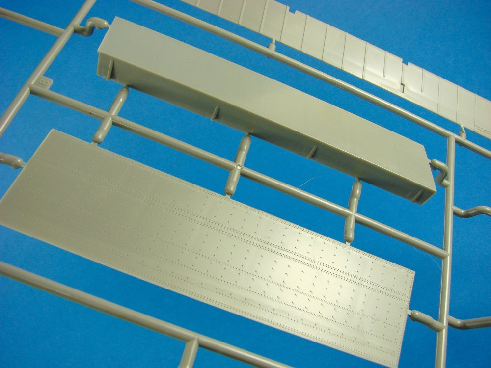
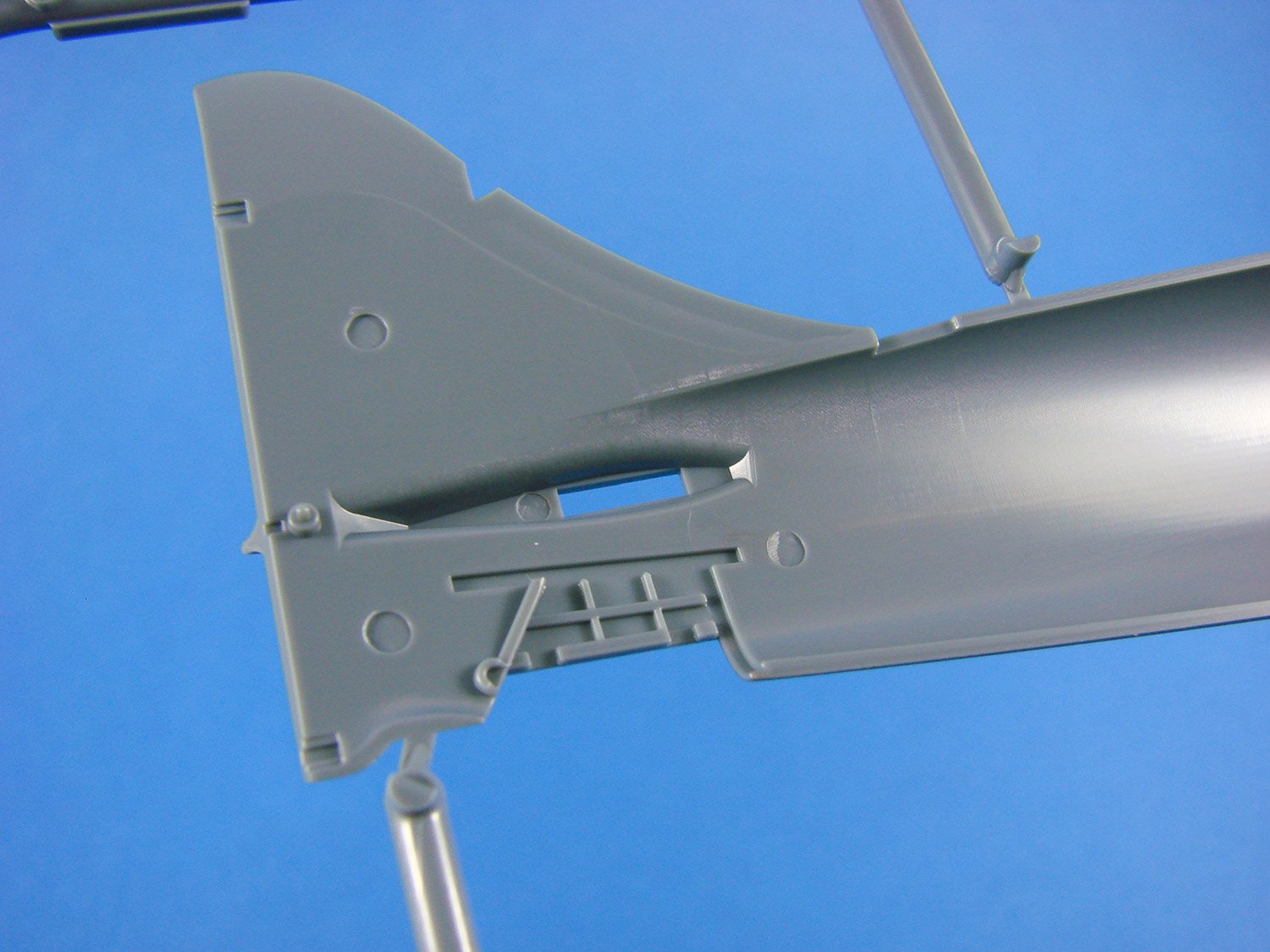
Our last sprue contains key areas of the Tempest airframe. Two propellers are supplied, but only one is to be used in this initial release. These are moulded as single-piece units and integral hubs. Two spinner options are provided, but one only for use with this kit. Here you will see the two-part stabilisers with separate elevators. Whilst these plug in, it will be easy to alter these so you can pose them dynamically. As with the other main airframe components, you’ll note the fine panel lining and subtle rivet lines. A key fuselage piece is the upper cockpit/turtle deck and canopy retract unit. Here you will see that the windscreen recesses nicely into this part. Another interesting design element is the main canopy interior frame that can of course be painted separately before installation, meaning that there is no actual interior masking to undertake.
A single piece rear cockpit bulkhead and integral armoured headrest and forward cockpit bulkhead are moulded here too.
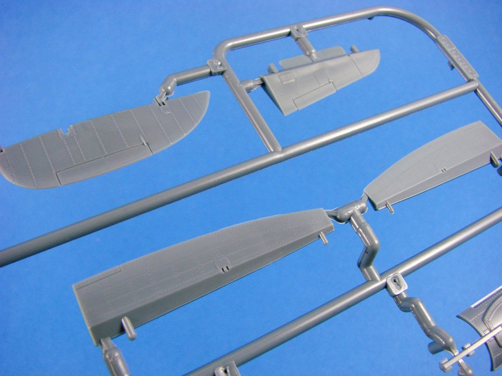

Other parts found here are the single piece metal ailerons, fabric covered rudder with nicely depicted rib tapes, and detailed landing gear doors.
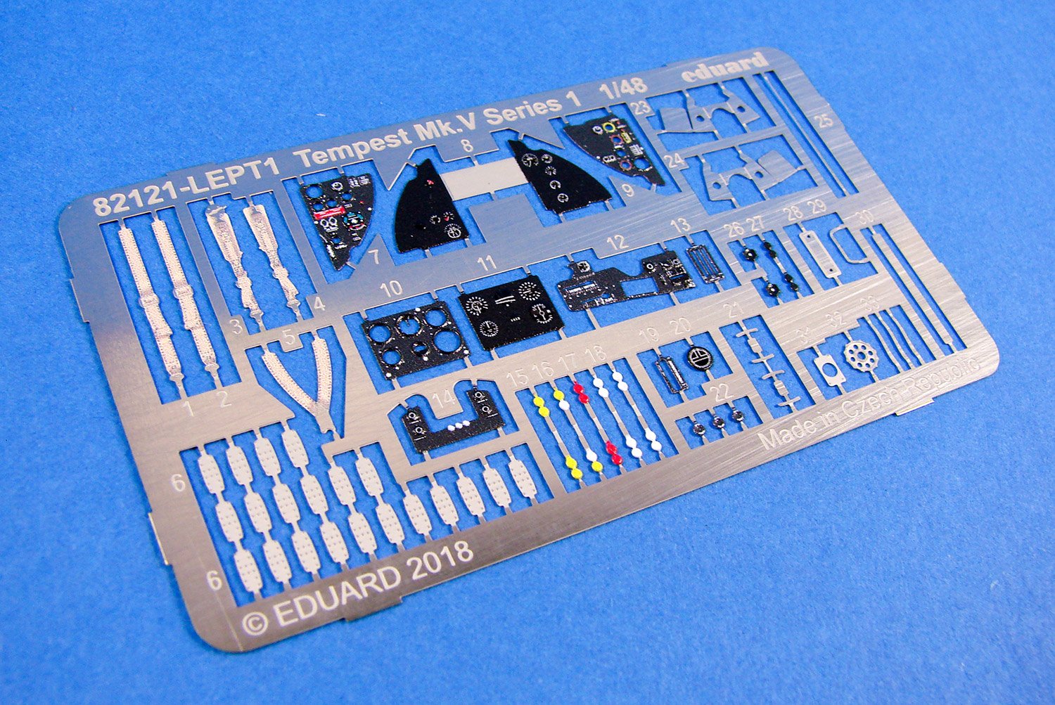
Photo Etch

There are quite a lot of parts on this small fret, with many of them printed in colour. Those parts pertain to the cockpit with the multi-part and multi-layer instrument panel and various levers with their coloured handles. A nicely shaded set of seatbelts is included here, as are a whole series of fishplate reinforcement parts. Production is typically Eduardin its quality with manufacture and printing being first-rate.
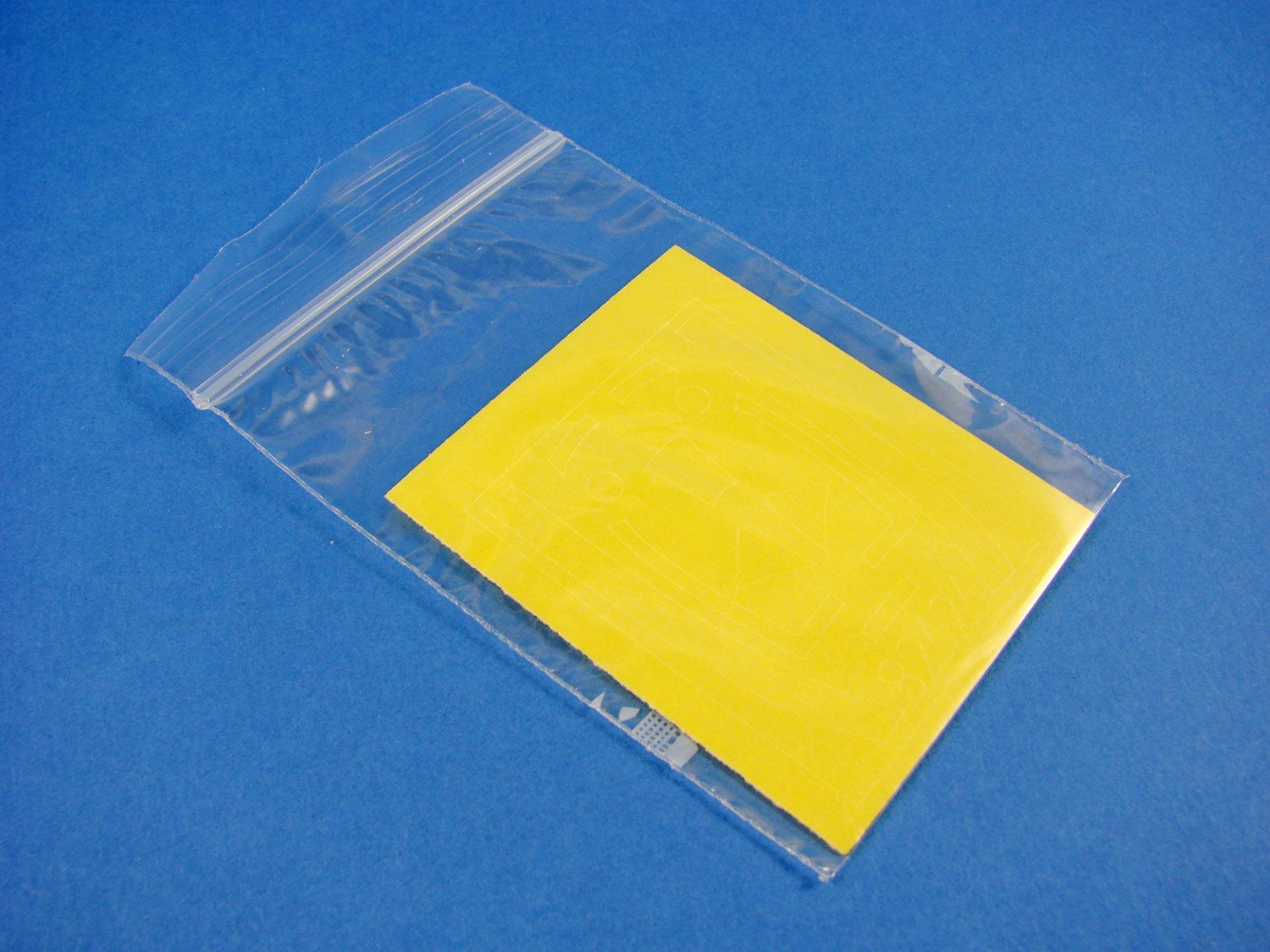
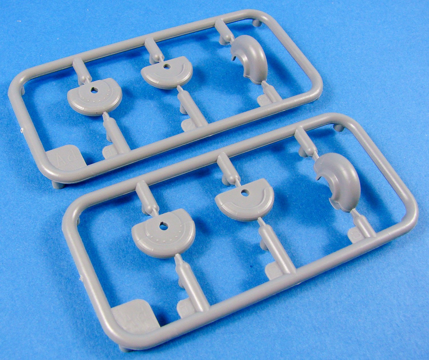
Masks
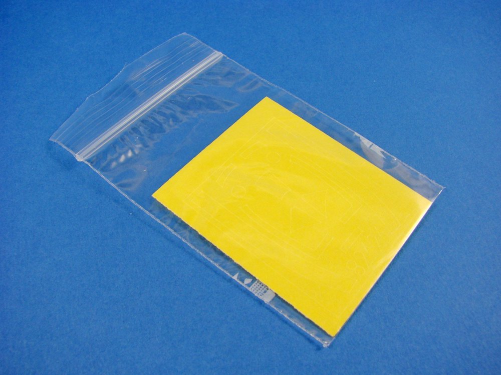
A set of kabuki tape masks is included for the canopy, wheel hubs and wing walkways. Strangely, no masks are supplied for the various airframe lights.
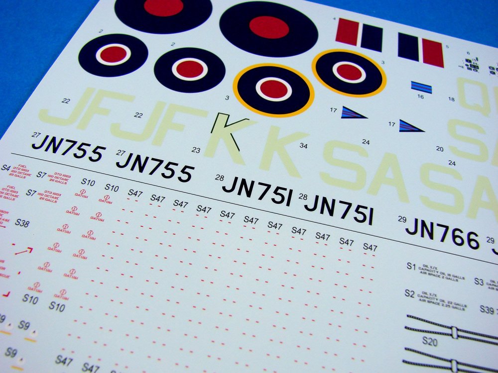
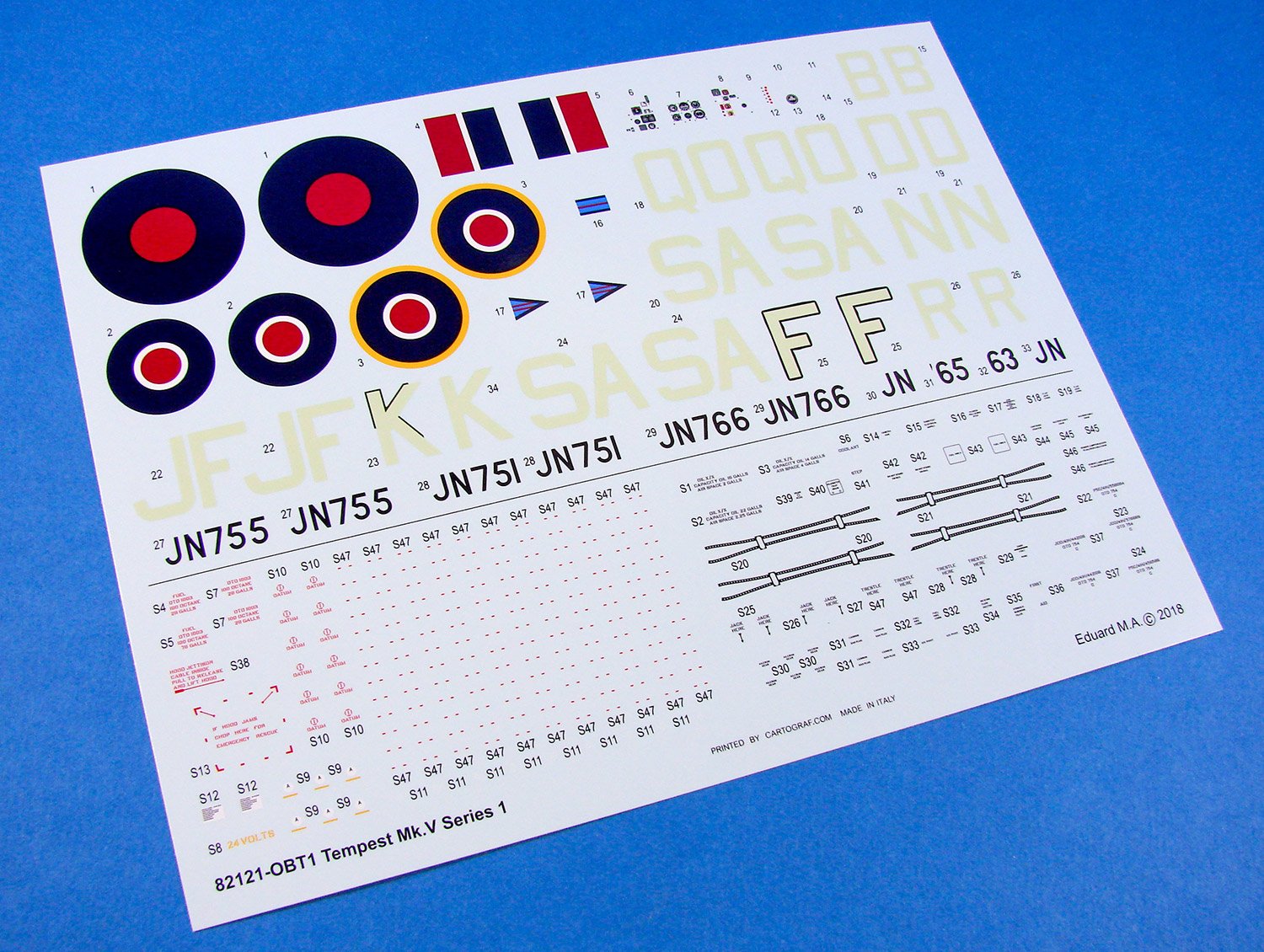
Decals
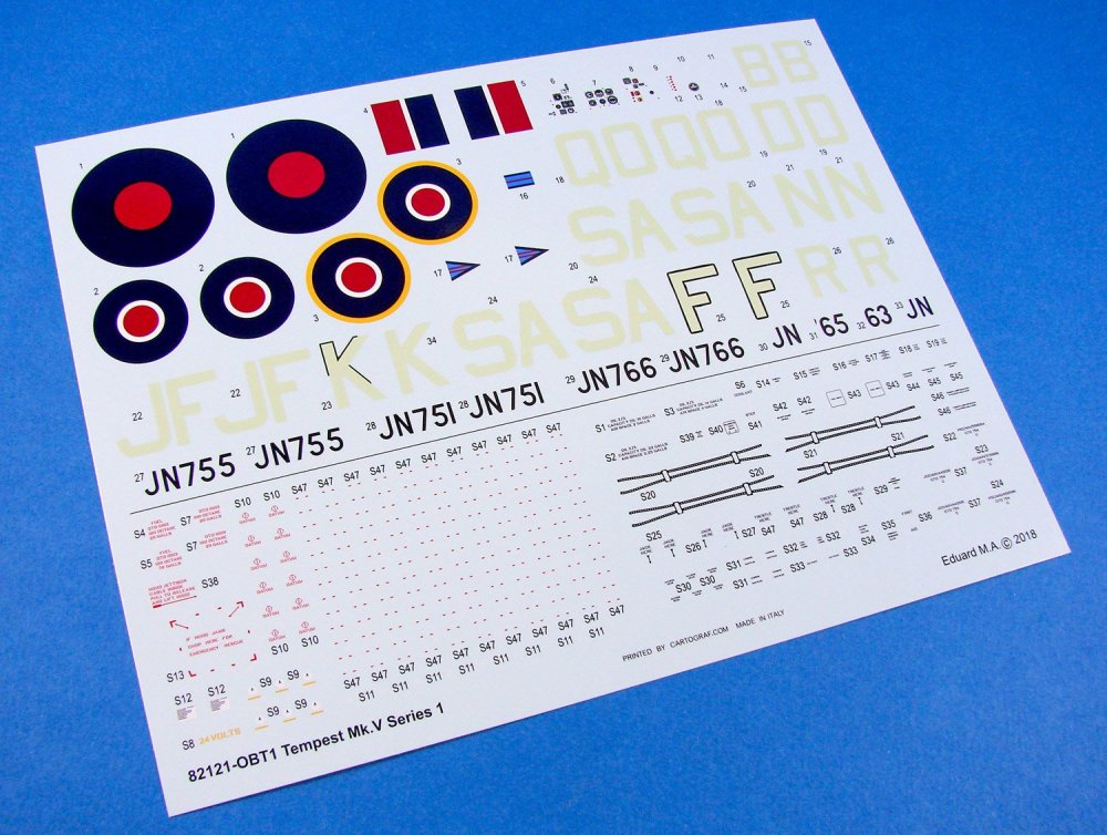
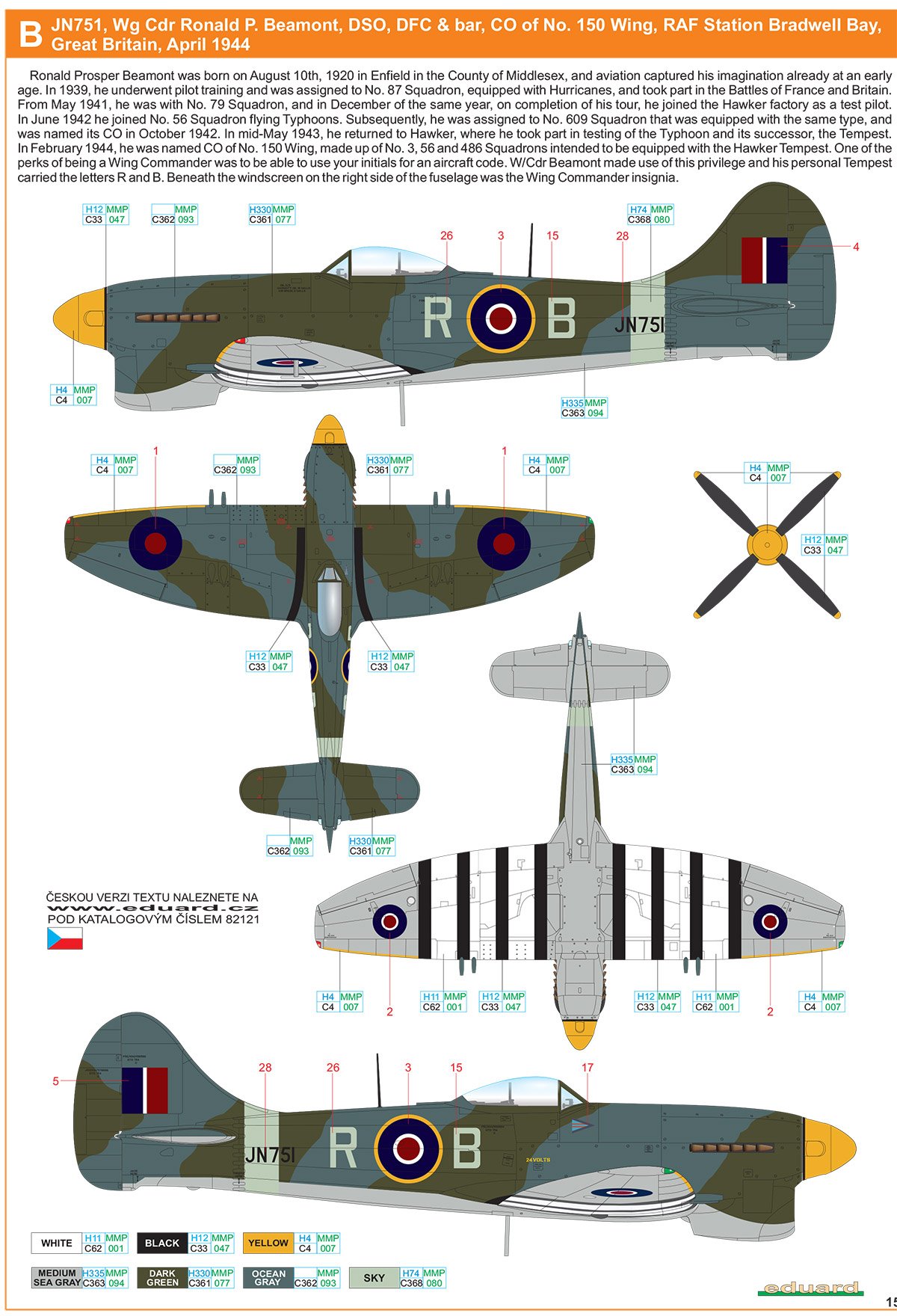
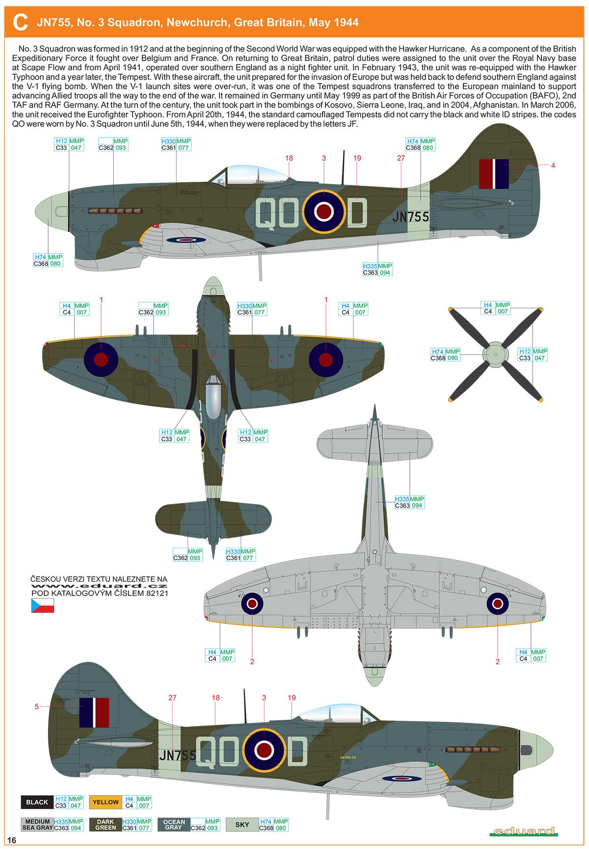
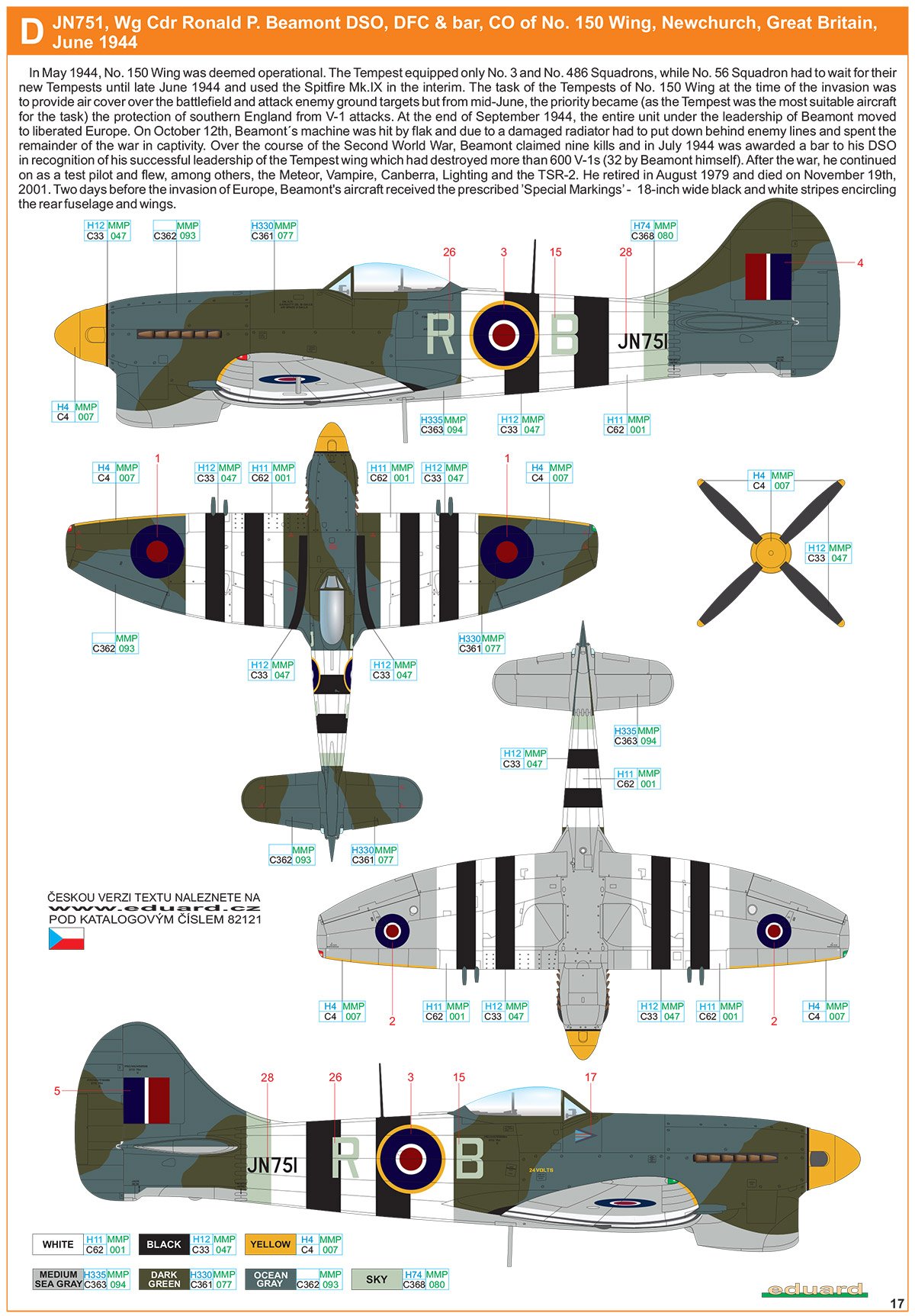
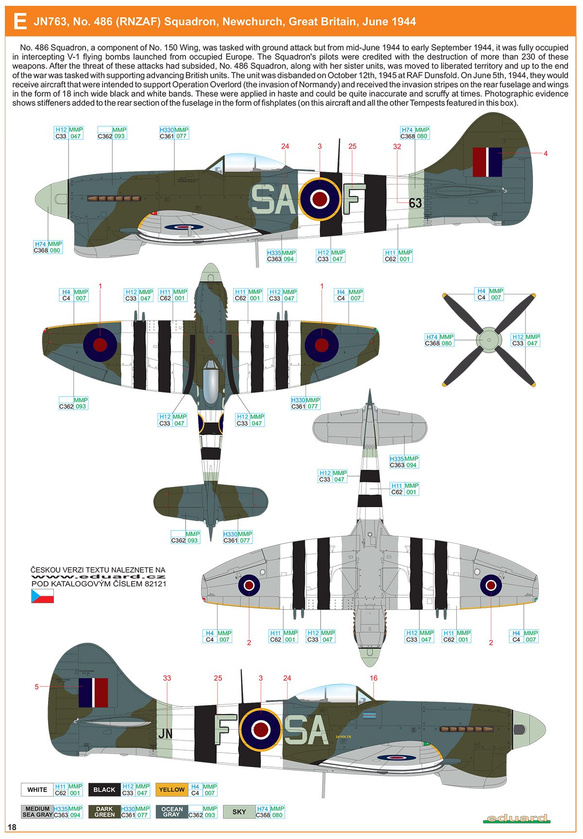
A single decal sheet is provided, catering to the SIX schemes in this release. Half of the sheet is dedicated to the various serials and codes, as well as the national insignia, whilst the other half caters to the many stencils for the airframe. Not all of these will be used, such as the drop tank decals. Printing is thin, has minimal carrier film, and has solid colour. Registration is also perfect.
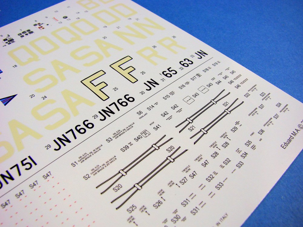
The six schemes included are:
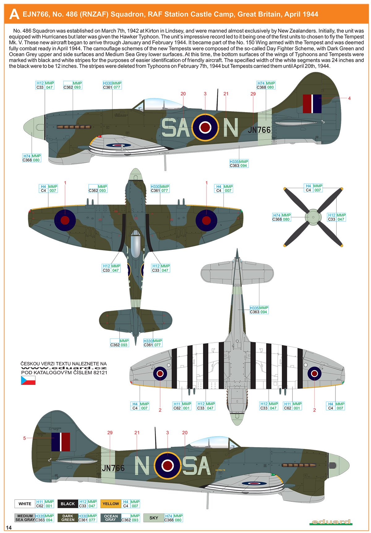
- EJN766, No.486 (RNZAF) Squadron, RAF Station Castle Camp, Great Britain, April 1944
- JN751, Wing Commander Roland P. Beamont, DSO, DFC & Bar, CO of No.150 Wing, RAF Station Bradwell Bay, Great Britain, April 1944
- JN755, No.3 Squadron, Newchurch, Great Britain, May 1944
- JN751, Wing Commander Roland P. Beamont, DSO, DFC & Bar, CO of No.150 Wing, RAF Newchurch, Great Britain, June 1944
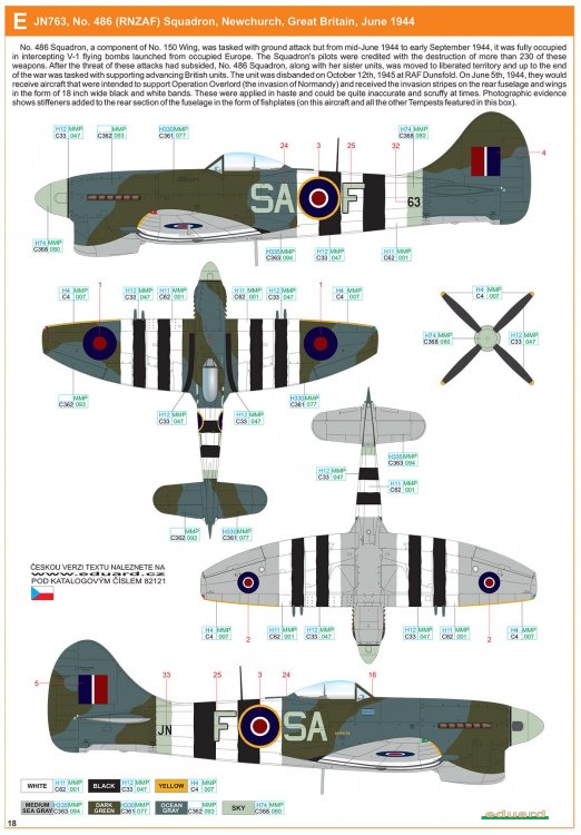
- JN763, No.486 (RNZAF) Squadron, Newchurch, Great Britain, June 1944
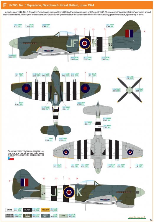
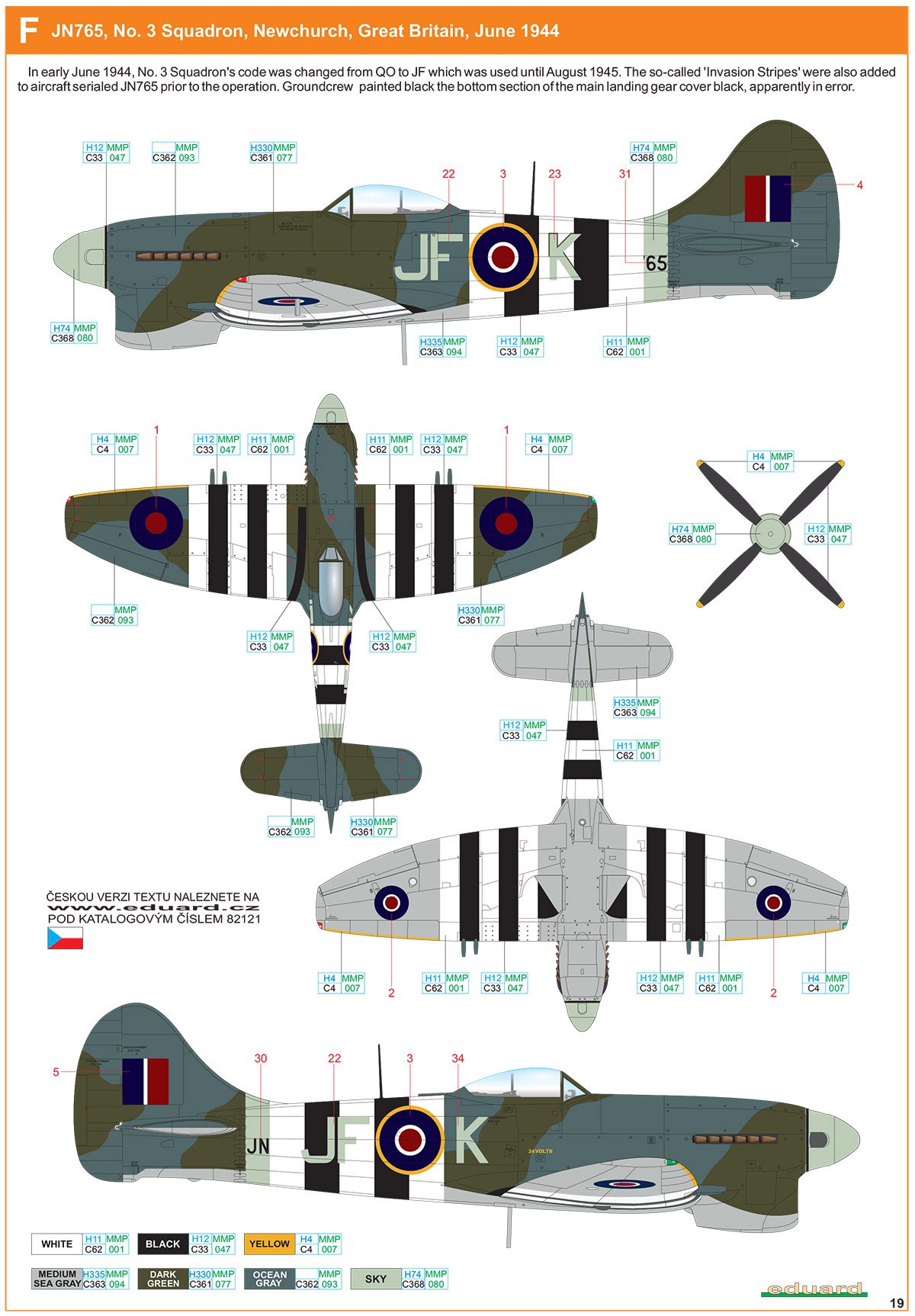
- JN765, Mo.3 Squadron, Newchurch, Great Britain, June 1944
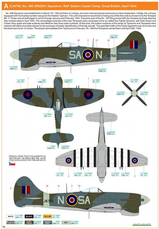
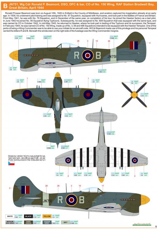

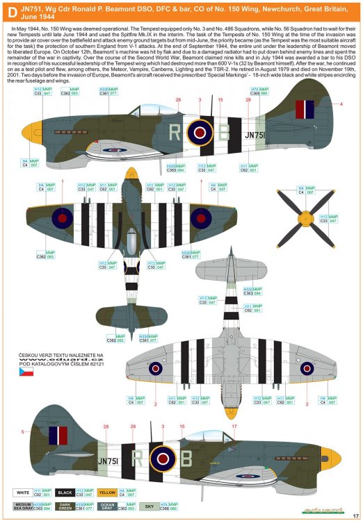
Instructions

Starting with a rather comprehensive history of the Tempest, this A4 colour manual then provides a parts map of the sprues with shaded areas for unused elements, followed by the construction of the Tempest in black/white/shaded illustration. Paint references are given throughout and correspond to Gunze and Mission Models colour codes. The last pages are given over to the six schemes, with the very last page containing a stencil placement illustration.
Conclusion
This is certainly a very welcome release, and of course one in Eduard’s modern tooling standard. This very much puts Eduard’s 20yr old release out to pasture, and it’s not hard to see why. Beautifully detailed cockpit and gear bays, and modern renditions of the various surface textures, this really is one to pick up if you have a hankering to build a Tempest and missed out on the now discontinued original Tempest release. Just a great, great kit! Watch out for the release date and you won’t be disappointed.My sincere thanks to Eduard for the sample reviewed here. Check out their social media and website for more information on release date for the Tempest.

-
 7
7
-
I got some pretty nice stuff at Telford, including some samples from RB Productions. I also picked up these:

-
5
-
-
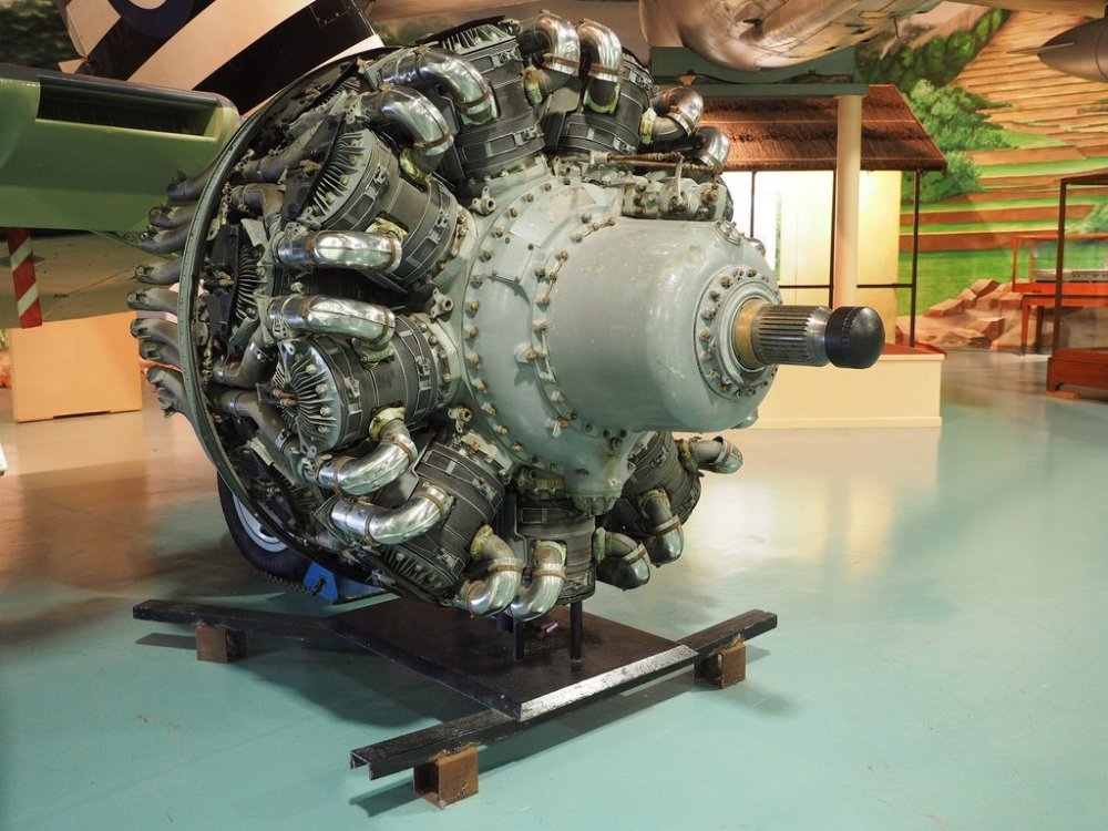
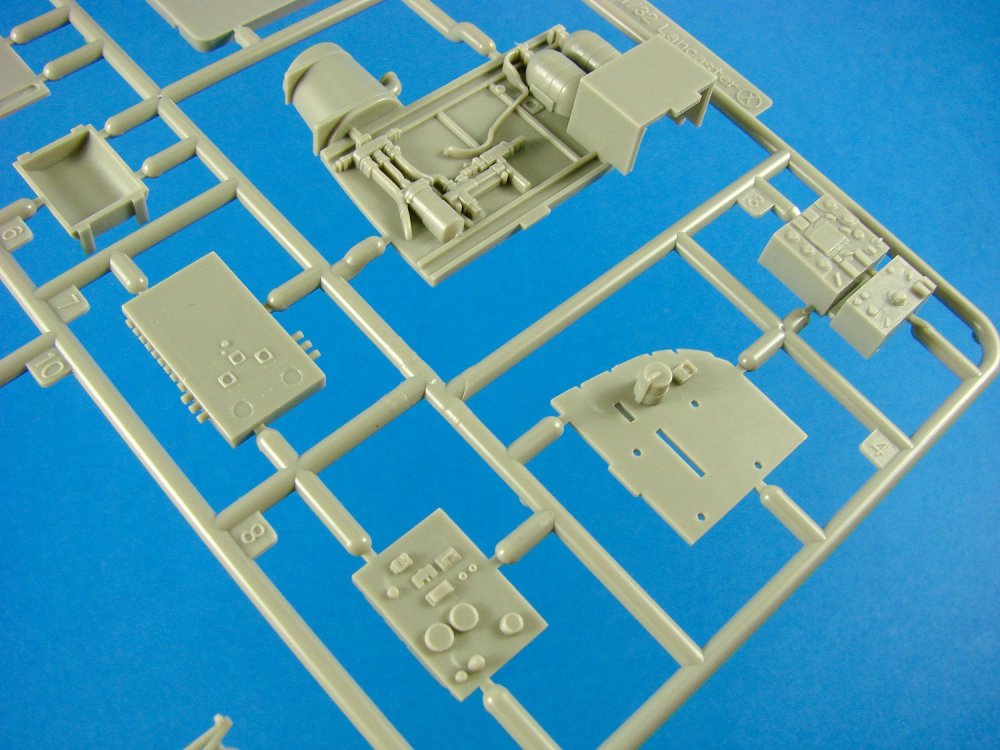
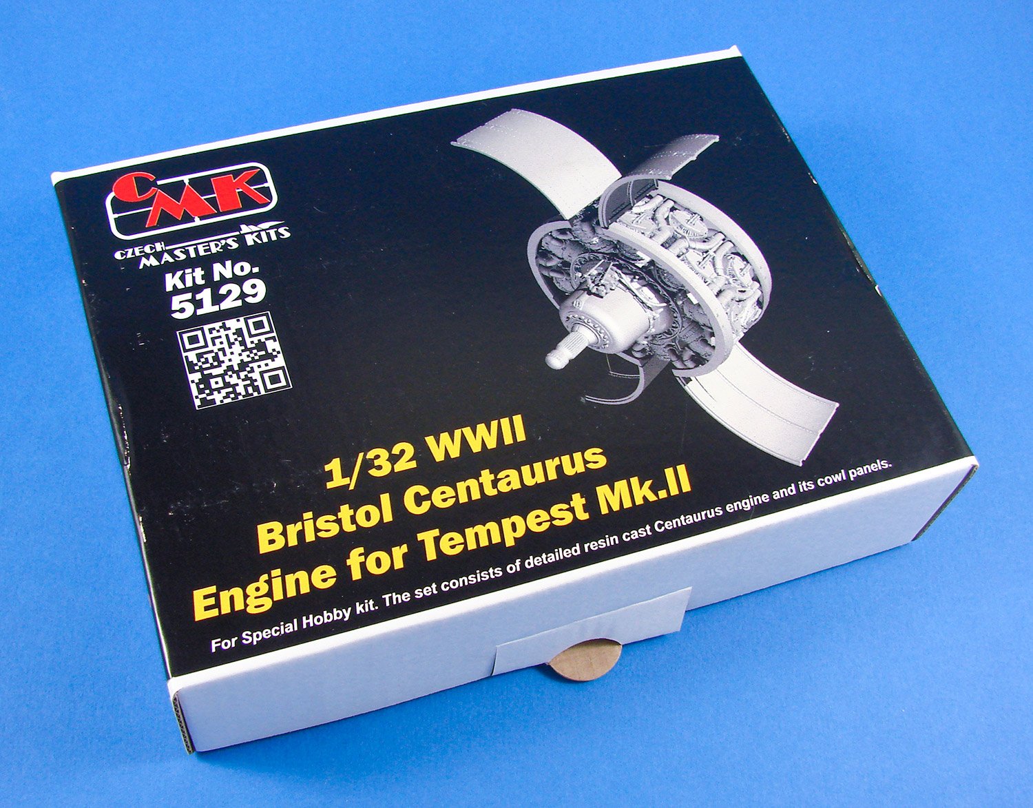
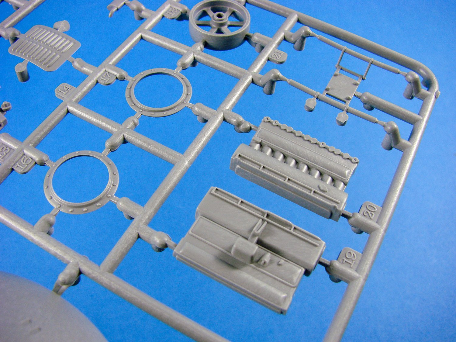
1:32 WWII Bristol Centaurus engine
Designed for Special Hobby Tempest Mk.II
Catalogue # 129-5129
Available from Special Hobby for €52,92
The Centaurus was the final development of the Bristol Engine Company's series of sleeve valve radial aircraft engines. The Centaurus is an 18-cylinder, two-row design that eventually delivered over 3,000 hp (2,200 kW). The engine was introduced into service late in the Second World War and was one of the most powerful aircraft piston engines to see service. Like most Bristol Engines designs, the Centaurus was based on the mechanicals of an earlier design, in this case the "classic" 5.75 in (146 mm) piston from their original 1918 Jupiter. The Jupiter piston was in use in the contemporary 14-cylinder Hercules, which was being brought into production during the design of the Centaurus.
e Centaurus did not see service until near the end of the war, first appearing on the Vickers Warwick. Other wartime, or postwar, uses included the Bristol Brigand and Buckmaster, Hawker Tempest and Sea Fury and the Blackburn Firebrand and Beverley. The engine also saw post-war use in civilian airliners, including the ill-fated Bristol Brabazon. By the end of the war in Europe, around 2,500 examples of the Centaurus had been produced by Bristol. The most powerful version of the Centaurus was intended for the Blackburn Beverley transport aircraft. Using direct fuel injection, it achieved a remarkable 3,220 hp, but was never fitted. The Centaurus was produced in 34 variants, ranging from the 2,000 hp (1,490 kW) Centaurus I to the 2,405 hp (1,793 kW) Centaurus 663 for the Airspeed Ambassador airliner. The most powerful variants to enter service were the 2,625 hp (1,957 kW) Centaurus 170, 173, 660, 661 and 662.
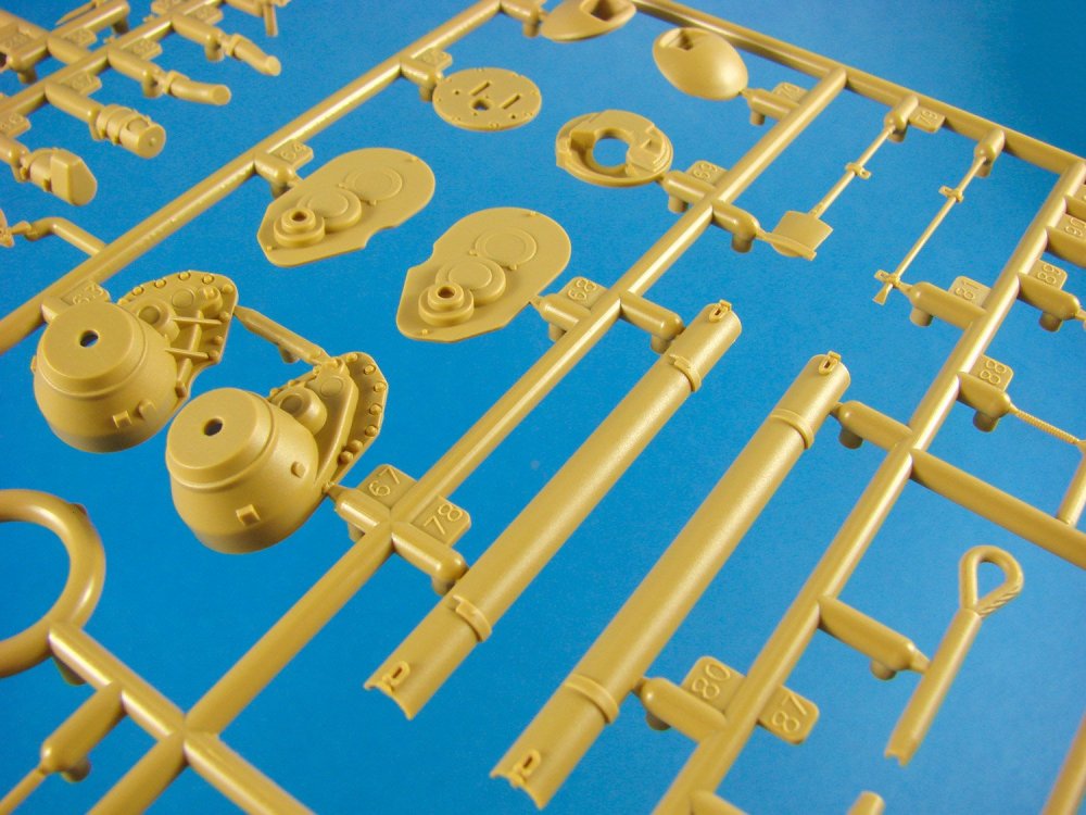
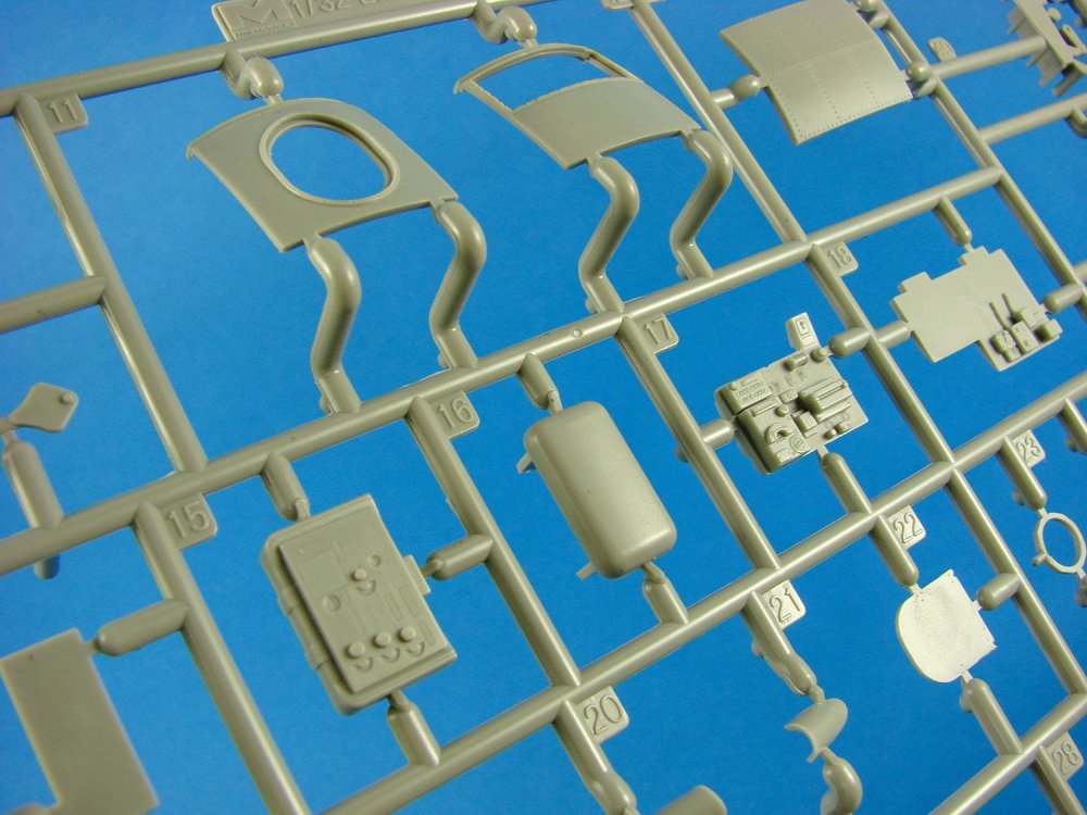
The kit

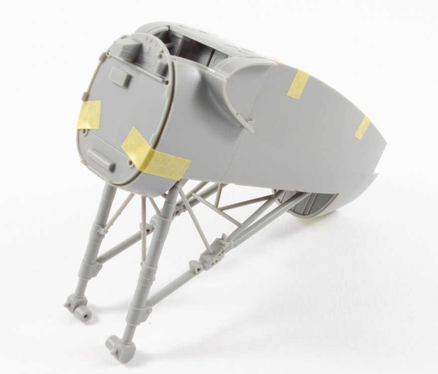
Like the Tempest Mk.V/VI before it, CMK has catered to the recent Special Hobby Tempest Mk.II by producing a resin engine detail/upgrade set. Of course, the previous engine release was the Napier Sabre, but this time it’s the turn of the powerful Bristol Centaurus to get the full treatment. Firstly, these sets are designed for modellers with some experience in resin and the intricacies of what can only be described as super-detail, so please be aware of this before you purchase. This set is only designed for those that wish to display the actual engine, with cowls opened. That might sound pretty obvious, but it would be a waste of your resources to try to cram it all in and cowl it over when all you can see is a small portion between the cowl and spinner. As it stands, the kit already has a moulded engine face which can be suitably painted for that approach.
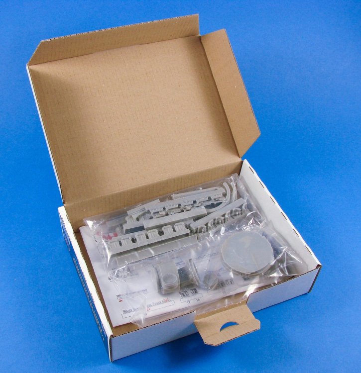

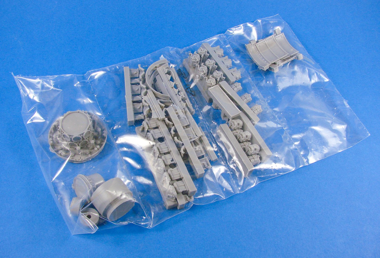
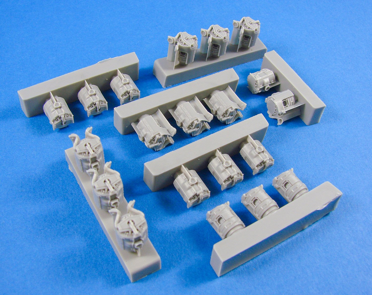
CMK’s Bristol Centaurus is packaged into a small but sturdy corrugated cardboard box, with a product label affixed to the underside. Entry is via the topside tab which opens to reveal a clear plastic sleeve that’s been heat-sealed into four compartments which contain the various engine parts. These are roughly grouped so you can find things a little easier. There are a LOT of parts here too, with approximately one hundred components, all cast in light grey resin. I did note a little greasiness to some parts with mould-release agent, so these will need to be gently washed or popped in my ultrasonic bath for a couple of minutes. As there is a LOT of resin here and cutting that sleeve open does leave the parts vulnerable to loss, it’s probably a good idea to pop them into small zip-lock wallets.
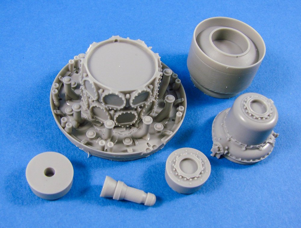
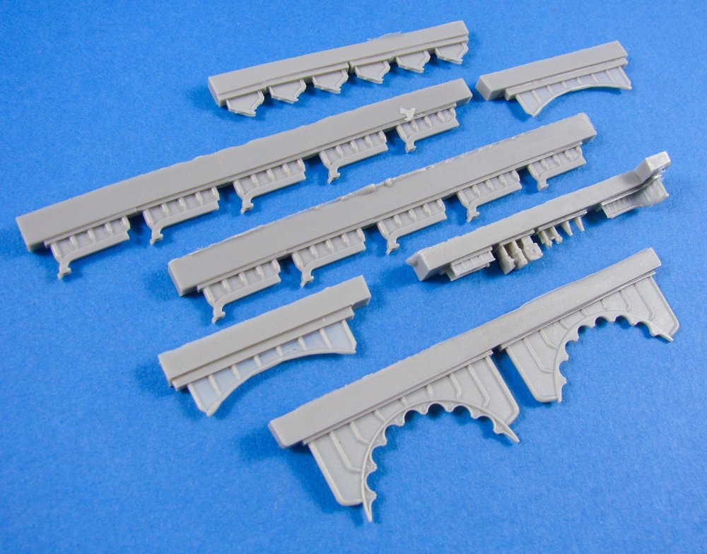
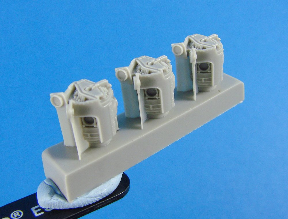
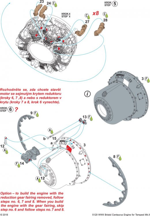
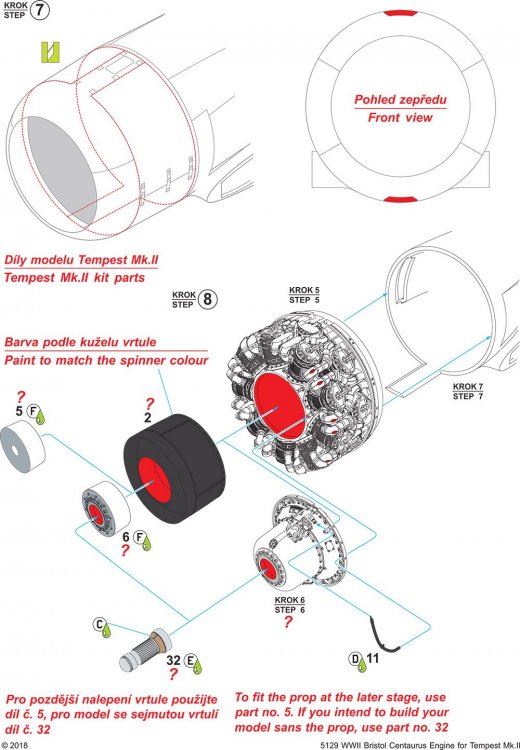
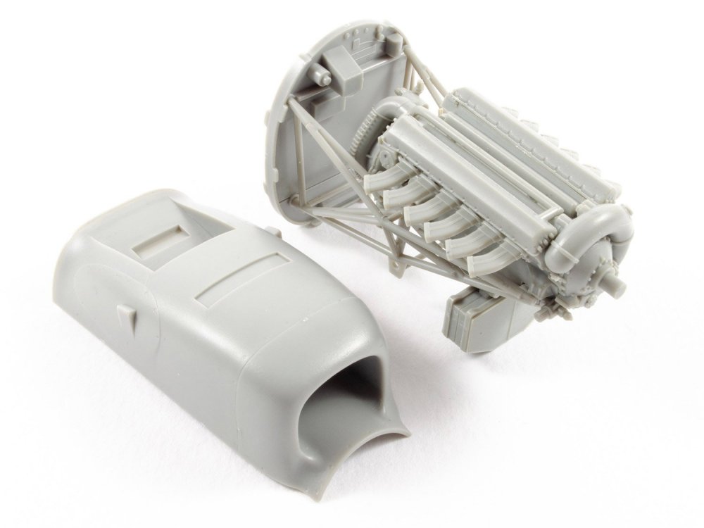
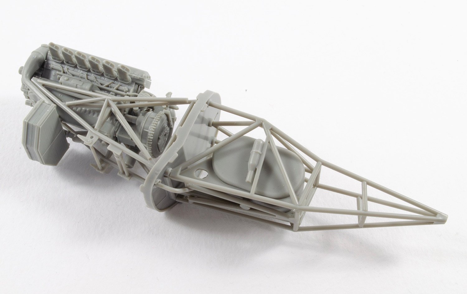
The major component around which everything else will be fitted is the crankcase with its integral firewall and details such as the exhaust outlet system. Detail is quite astonishing, with nicely shaped recesses into which the cylinders will fit. Also in this first compartment of parts is the keyed propeller shaft and a rather nice option that’s been made available to the modeller, and that is to model the reduction gear with or without the fairing. On a model with the front cowl and prop in position, you would use the part with the housing of course, but for a nice strip-down maintenance diorama, then you can use the part with all the reduction gear on show in all its glory. For the fairing gear option, you can choose to either add the forward hub detail in a propeller-off scenario, or just the plain part if prop in situ. Looks like CMK covered all scenarios here.
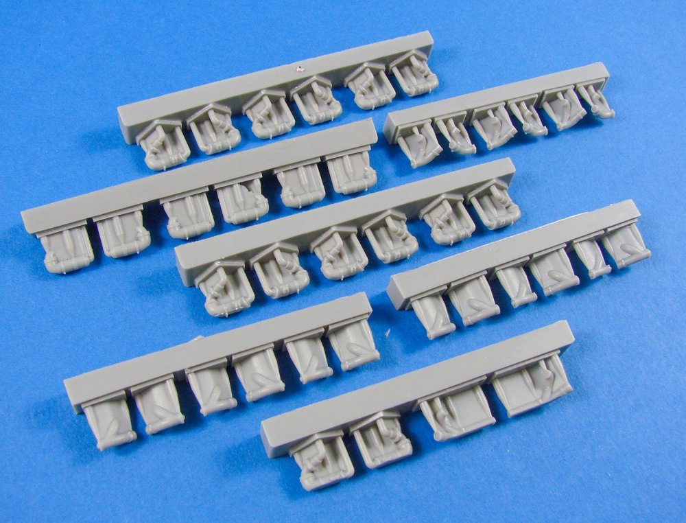

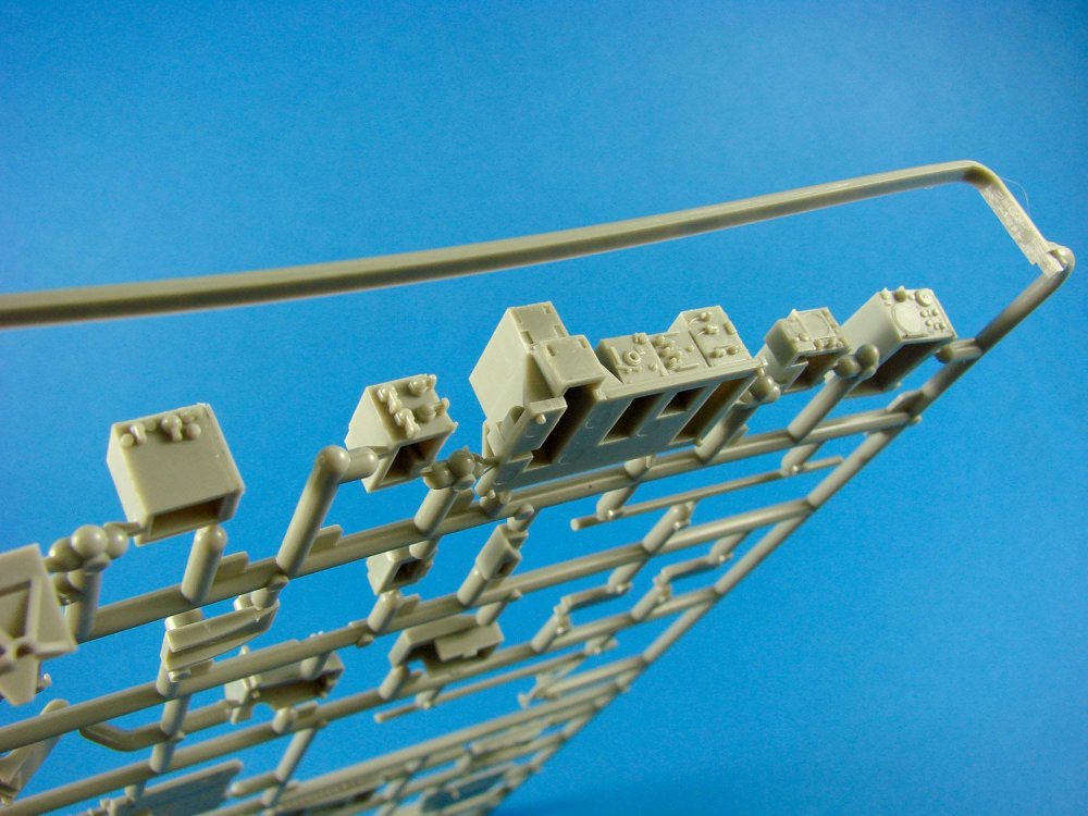
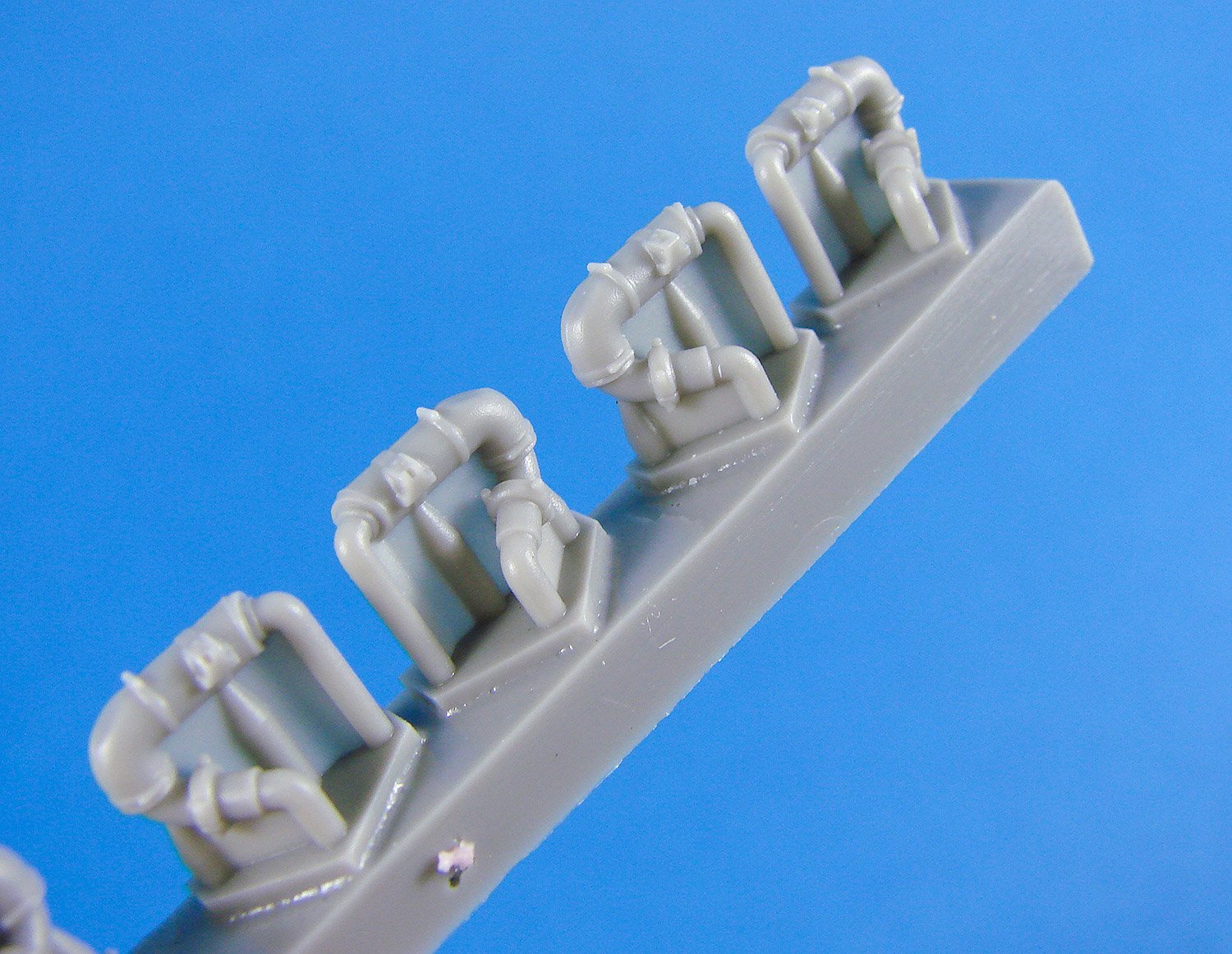
Next up a series of exhaust manifold pipes will need to be removed from their casting blocks and any resin webs eliminated. This won’t be a quick job as you can see from the number of these in the photo, but you did sign up for high detail, right? Most of the material here will actually be removed and just a small pipe will be all that’s left, complete with unions, fastening clips etc. Excellent detail, all round. Just take your time.
No PE is supplied with this release, so things such as the engine frames, cowl latches and hinged arms etc. are made in resin and will need real care when removing and cleaning ready for assembly.
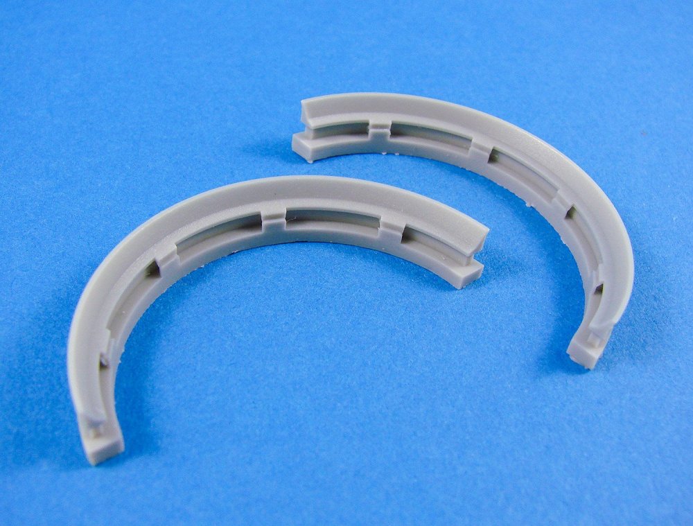
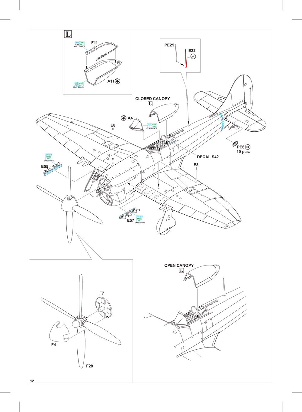
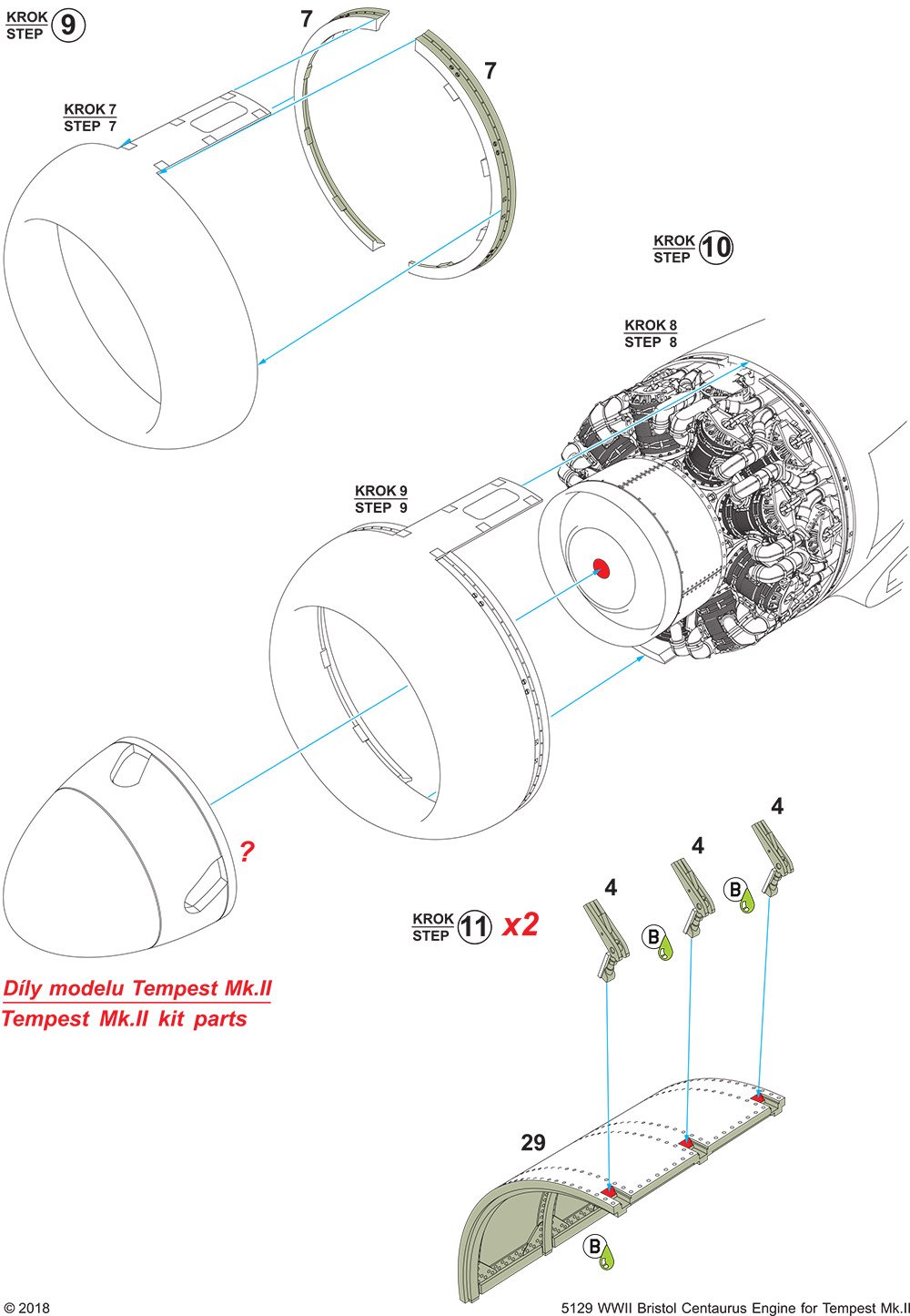
Of course, to fit this item to the kit will require some butchery of the mother styrene., and this is clearly shown in the instructions. You will need to check this against the resin cowl panels too, to ensure the removed material equates to the new resin. Two resin pieces are supplied for the edge of the nose ring cowl, and these can be used to also gauge the surgery required.
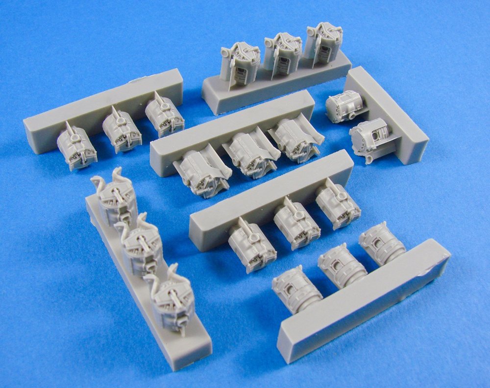
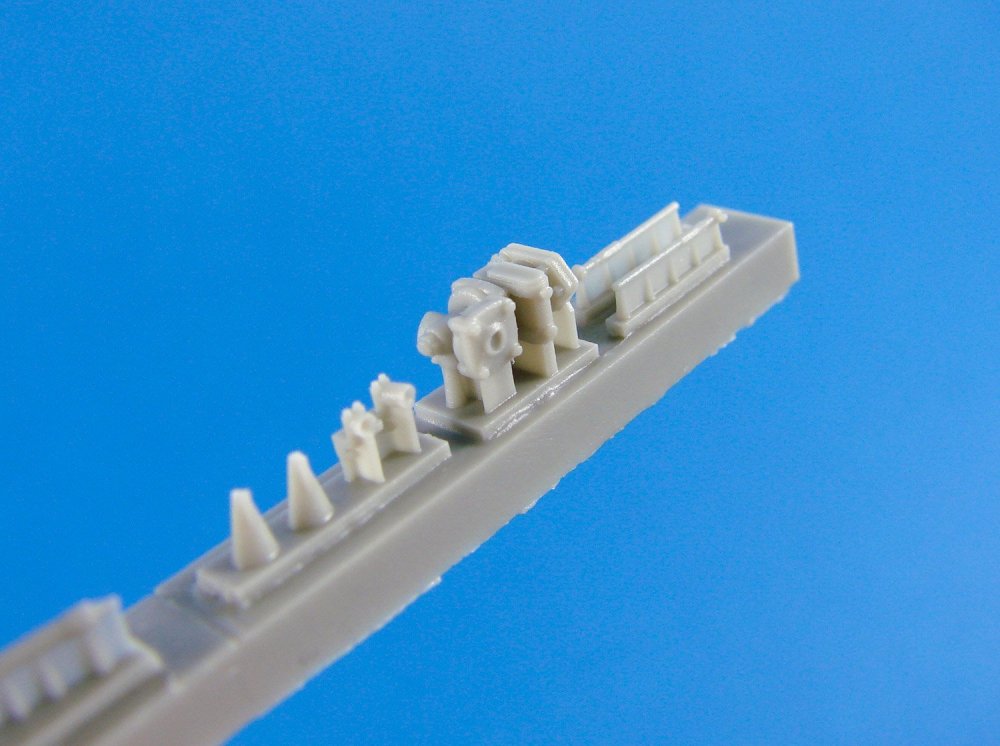
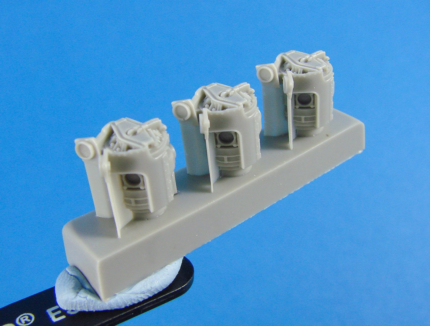
The cylinders themselves are absolutely stunning! Again, some resin webs will need removing. These are in situ to prevent breakage when the parts are removed from their moulds. I’ll leave the photos here to show how good they are. Exhaust plug-in holes are well-defined, and I can’t, at this moment, foresee any issues apart from the sheer complexity of the model itself. The completed engine is a very compact unit with many parts that need to fit tightly within its footprint.
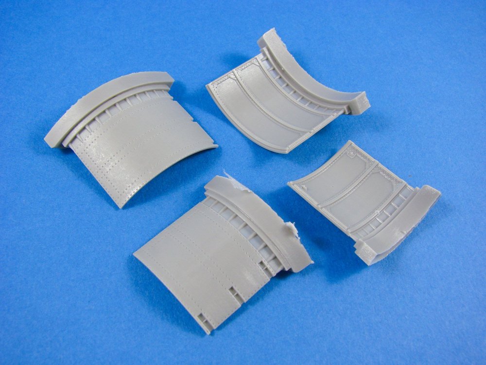

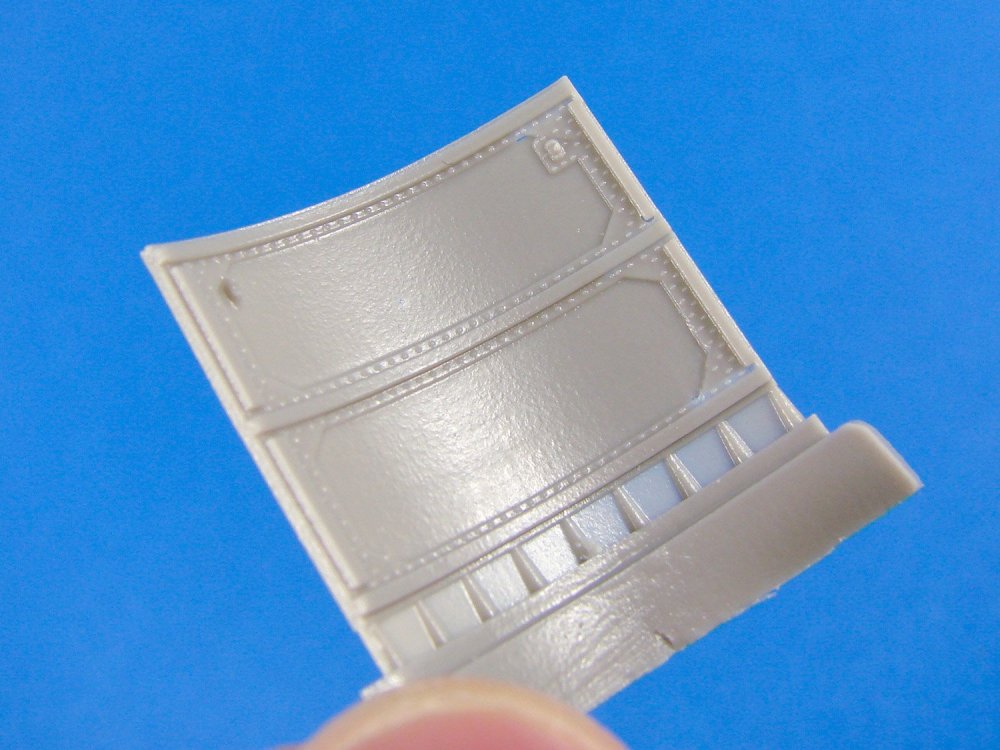
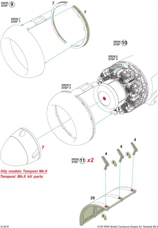
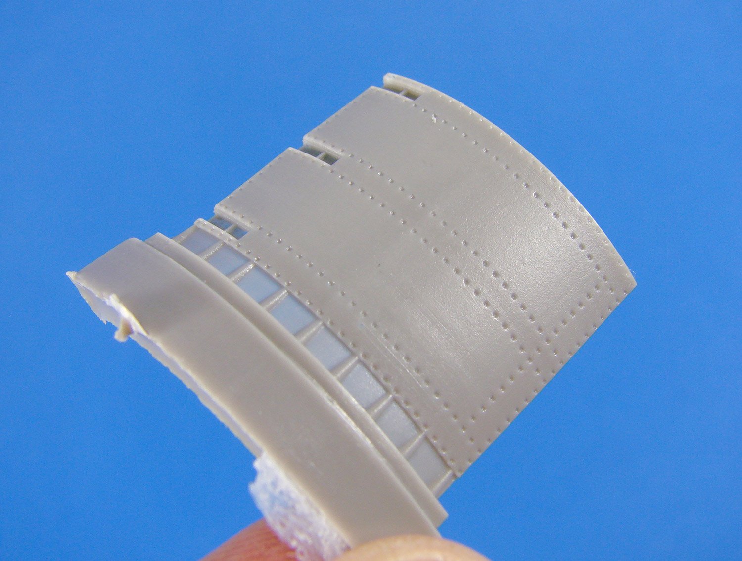
You will of course need new engine cowl panels to replace the plastic you cut from the kit, and to also display the internal details that they would have. Here we have four panels, with cleanly rendered details both internally and externally. External details are commensurate with the kit itself, so won’t look out of place.
Instructions
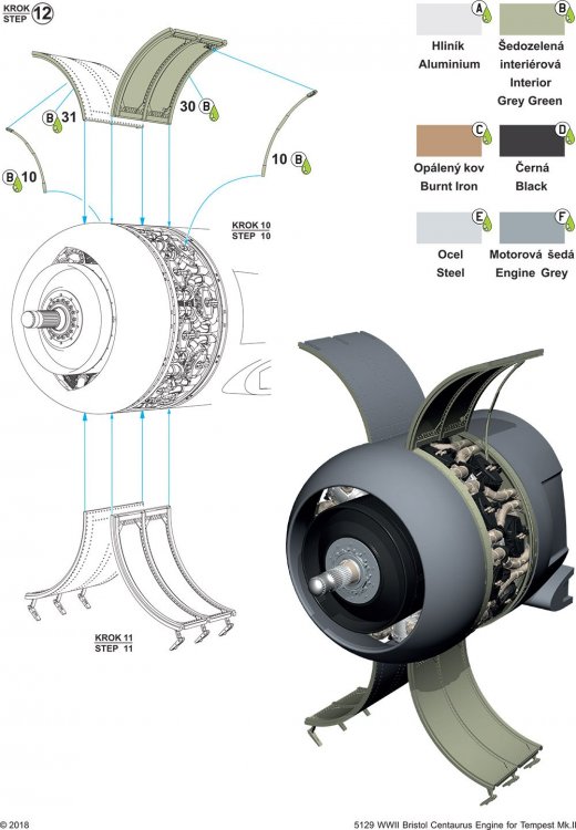
A series of folded instruction sheets detail modification of the kit and assembly/fitting of the engine, over a series of twelve constructional sequences, with some use of colour to highlight key areas. Whilst no paint codes are given, standard colour names are supplied, and these are referenced throughout construction.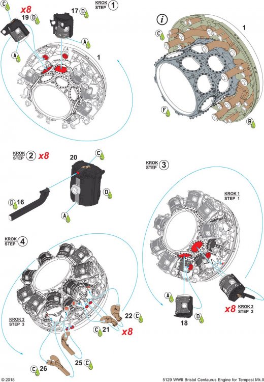
Conclusion
Another seriously nice release to enhance the excellent Tempest Mk.II kit from Special Hobby. I’m struggling to think of anything else that they need to cover now with the many detail sets now available. This set really is quite something and will doubtless build up into an accurate representation of this powerful engine, and provide a real focal point for the brutal-looking Tempest II. Whilst this is no beginner’s set, it would lend itself to those with some previous resin experience and the nerve to slice apart the host kit. In all, a real must havefor Tempest fans who like large scale detail.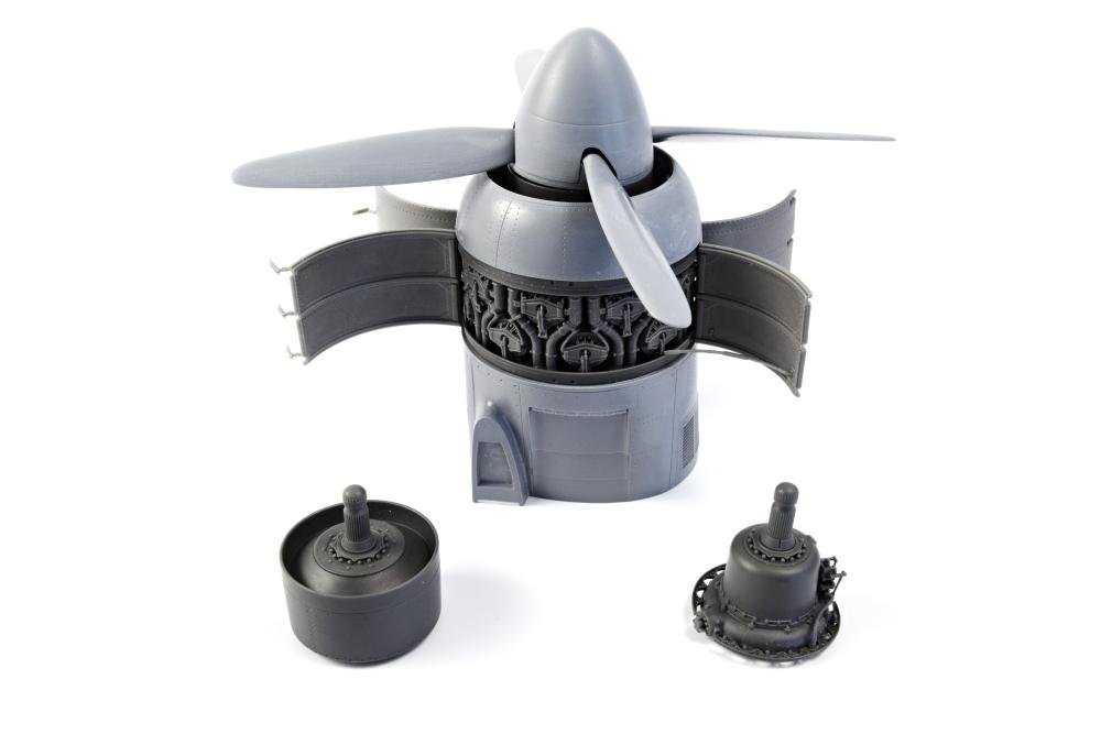
My sincere thanks to Special Hobby for the sample reviewed here. To purchase directly, click the link at the top of this article.

-
5
-
-
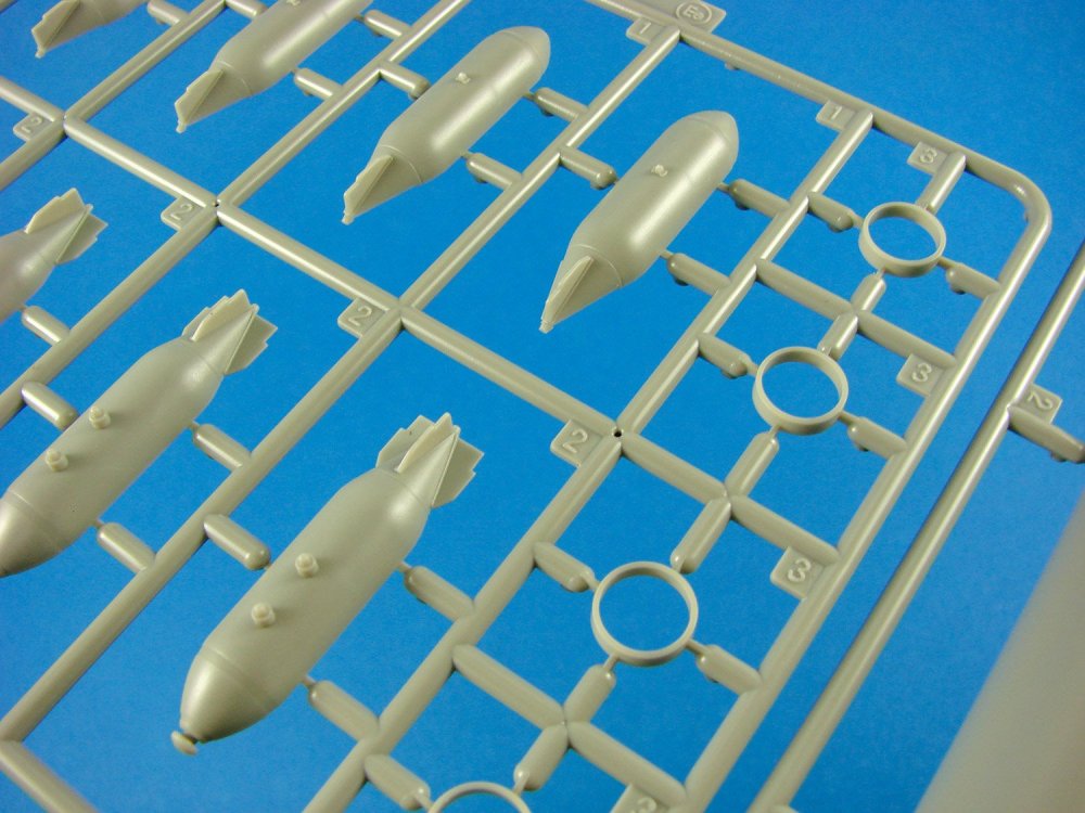
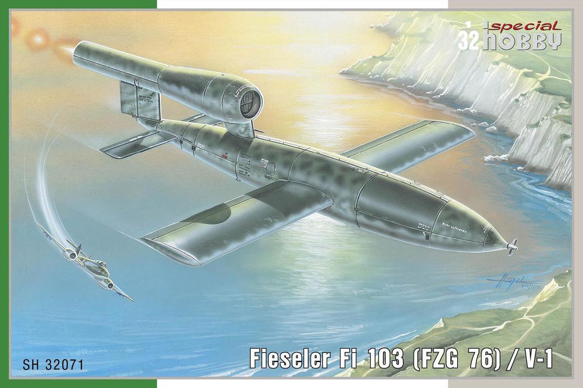
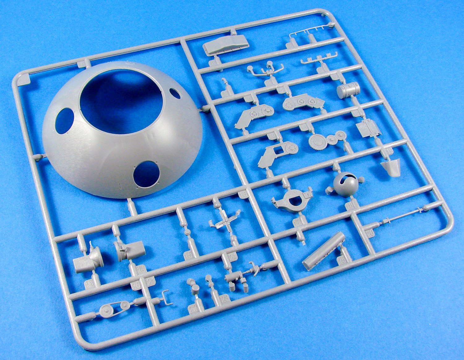
1:32 Fieseler Fi 103 (FZG 76)/V-1
Catalogue # SH32071
Special Hobby
Available from Special Hobby for €20,16
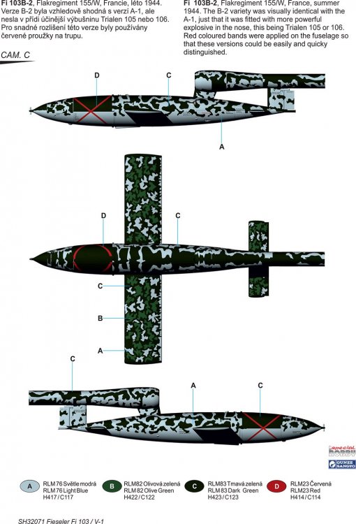
The V-1 flying bomb (German: Vergeltungswaffe 1 "Vengeance Weapon 1")—also known to the Allies as the buzz bomb, or doodlebug, was an early cruise missile and the only production aircraft to use a pulsejet for power. It was developed at Peenemünde Army Research Centre in 1939. Due to its limited range, the thousands of V-1 missiles launched into England were fired from launch facilities along the French (Pas-de-Calais) and Dutch coasts. The first V-1 was launched at London on 13 June 1944, one week after (and prompted by) the successful Allied landings in Europe. At peak, more than one hundred V-1s a day were fired at south-east England, 9,521 in total, decreasing in number as sites were overrun until October 1944, when the last V-1 site in range of Britain was overrun by Allied forces. After this, the V-1s were directed at the port of Antwerp and other targets in Belgium, with 2,448 V-1s being launched. The attacks stopped only a month before the war in Europe ended, when the last launch site in the Low Countries was overrun on 29 March 1945.
The V-1 had a fuselage constructed mainly of welded sheet steel and wings built of plywood, and the simple, Argus-built pulsejet engine pulsed 50 times per second, and the characteristic buzzing sound gave rise to the colloquial names "buzz bomb" or "doodlebug". The V-1 guidance system used a simple autopilot developed by Askania in Berlin to regulate altitude and airspeed. A weighted pendulum system provided fore-and-aft attitude measurement to control pitch, damped by a gyrocompass which also stabilized it. An odometer driven by a vane anemometer on the nose determined when the target area had been reached, accurately enough for area bombing. As the missile flew, the airflow turned the propeller, and every 30 rotations of the propeller counted down one number on the counter. The warhead was originally 1,000 kg of Amatol-39, later and the aluminised explosive Trialen, was later used. Fusing was by a triple fuse system. The main fuses were an electrical impact fuse and a mechanical backup impact fuse. These were immediate action fuses, the intention being to detonate the warhead on the first impact with the surface, rather than allowing itself to become buried first.
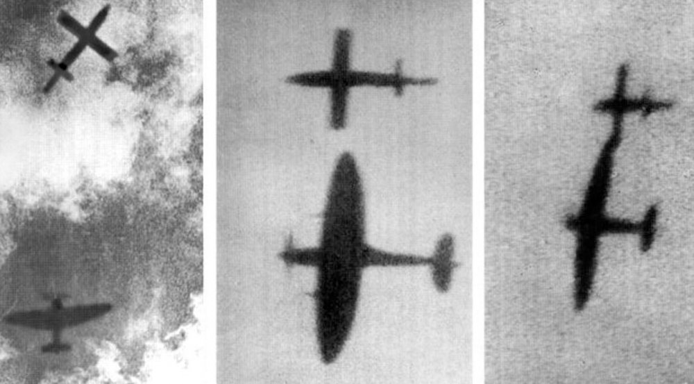
By September 1944, the V-1 threat to England was temporarily halted when the launch sites on the French coast were overrun by the advancing Allied armies. 4,261 V-1s had been destroyed by fighters, anti-aircraft fire and barrage balloons. The last enemy action of any kind on British soil occurred on 29 March 1945, when a V-1 struck Datchworth in Hertfordshire. The British operated an arrangement of air defences, including anti-aircraft guns and fighter aircraft, to intercept the bombs before they reached their targets as part of Operation Crossbow, while the launch sites and underground V-1 storage depots were targets of strategic bombing.
The kit
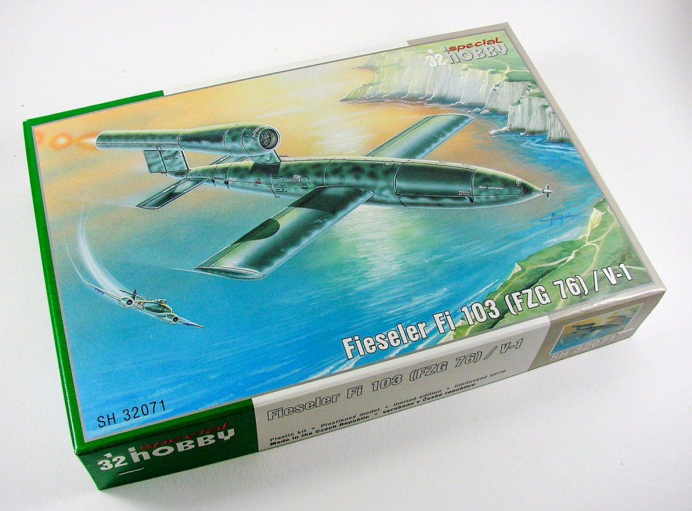
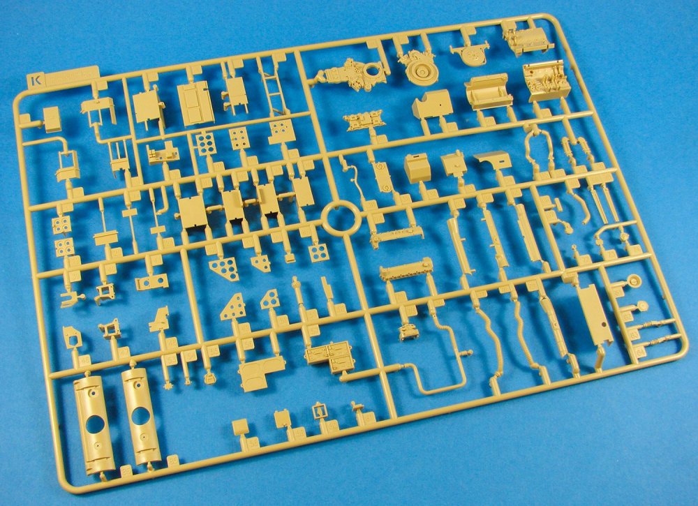
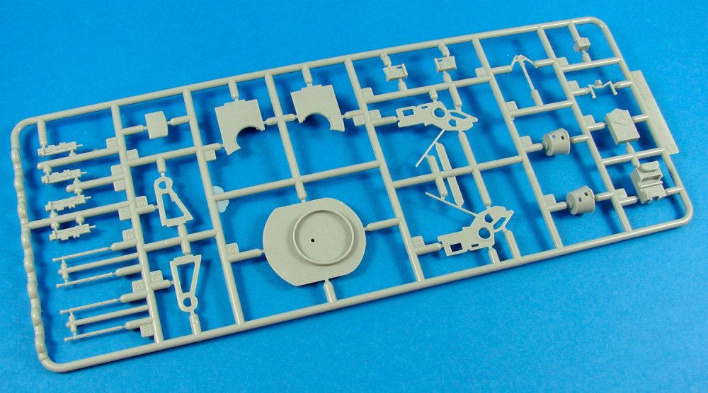
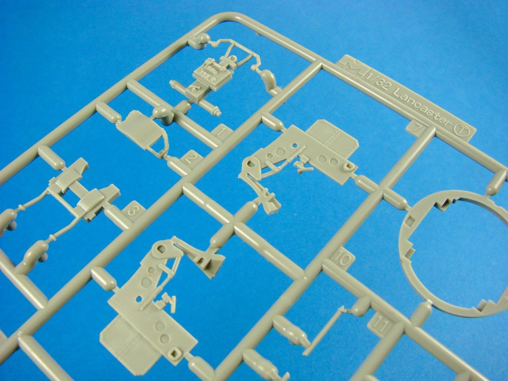
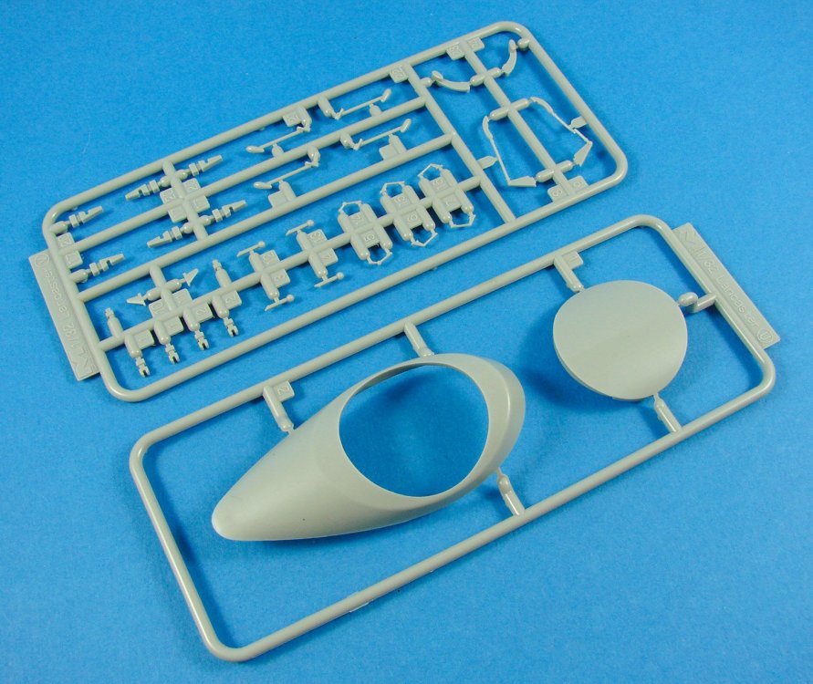
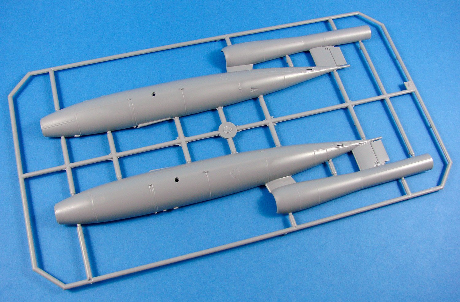
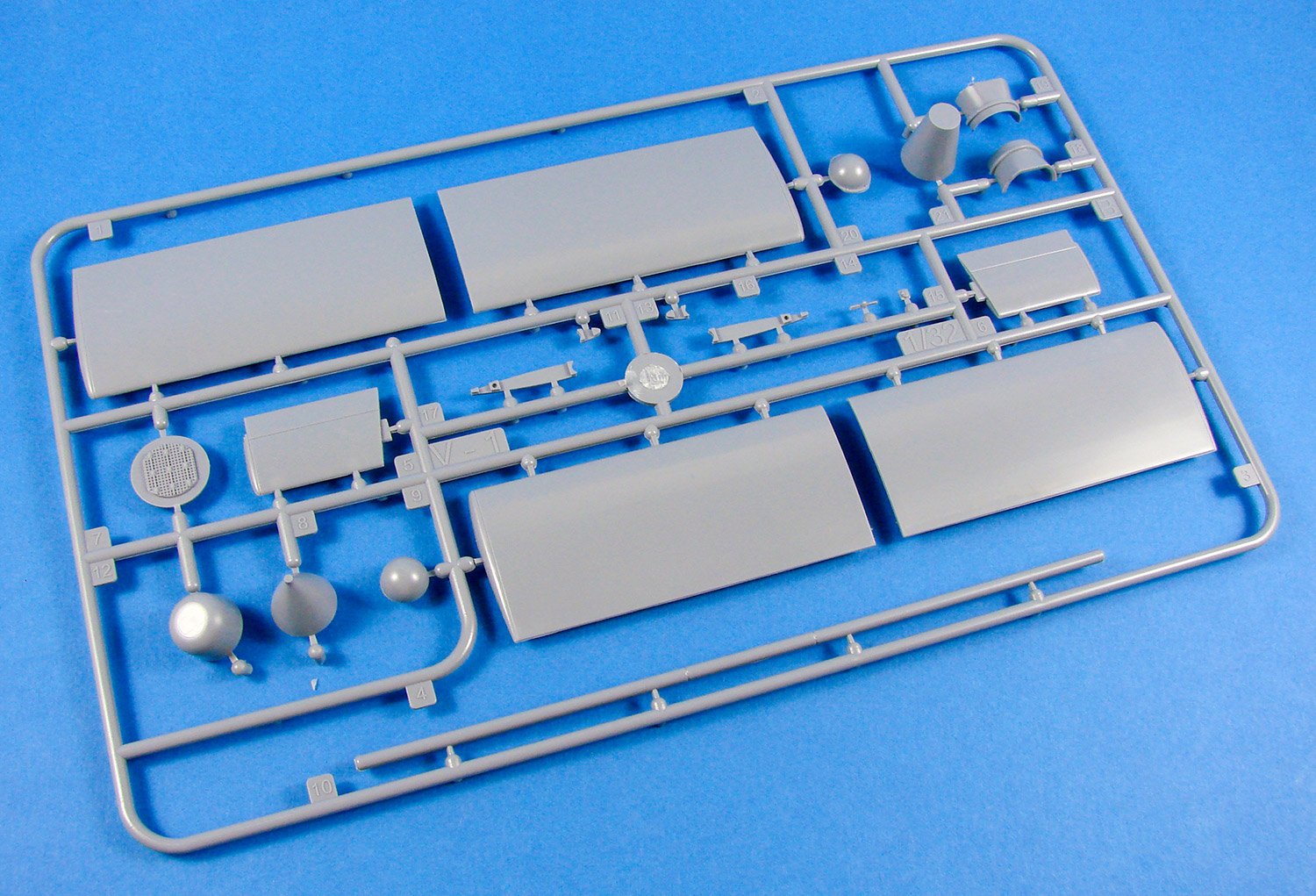
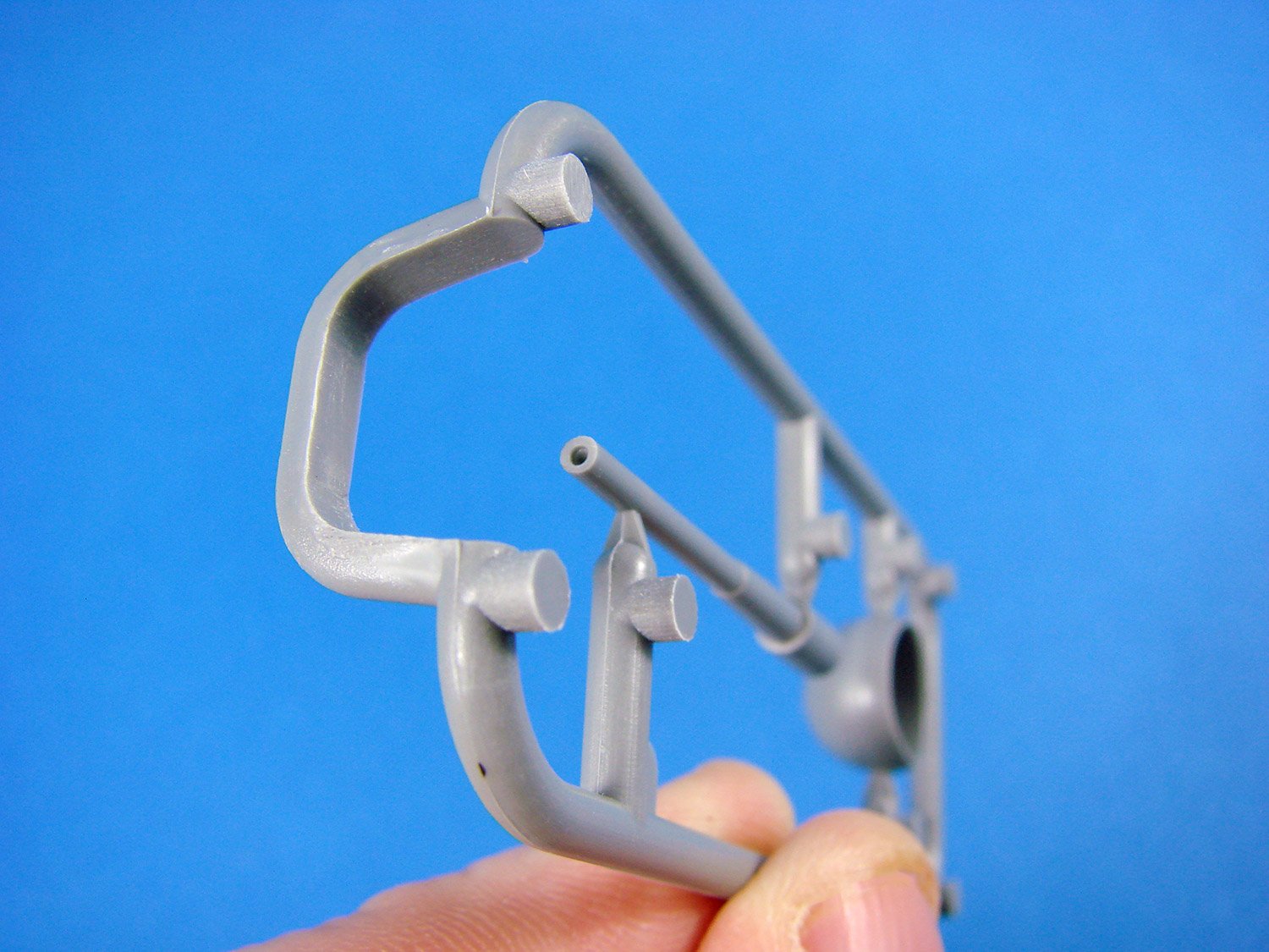
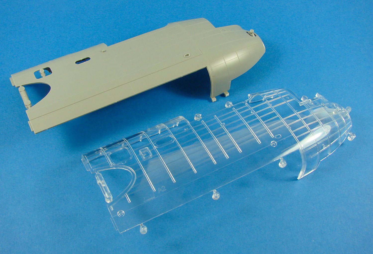
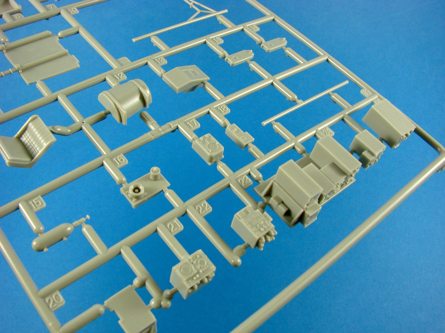
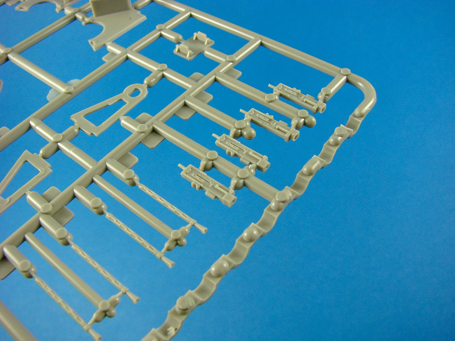
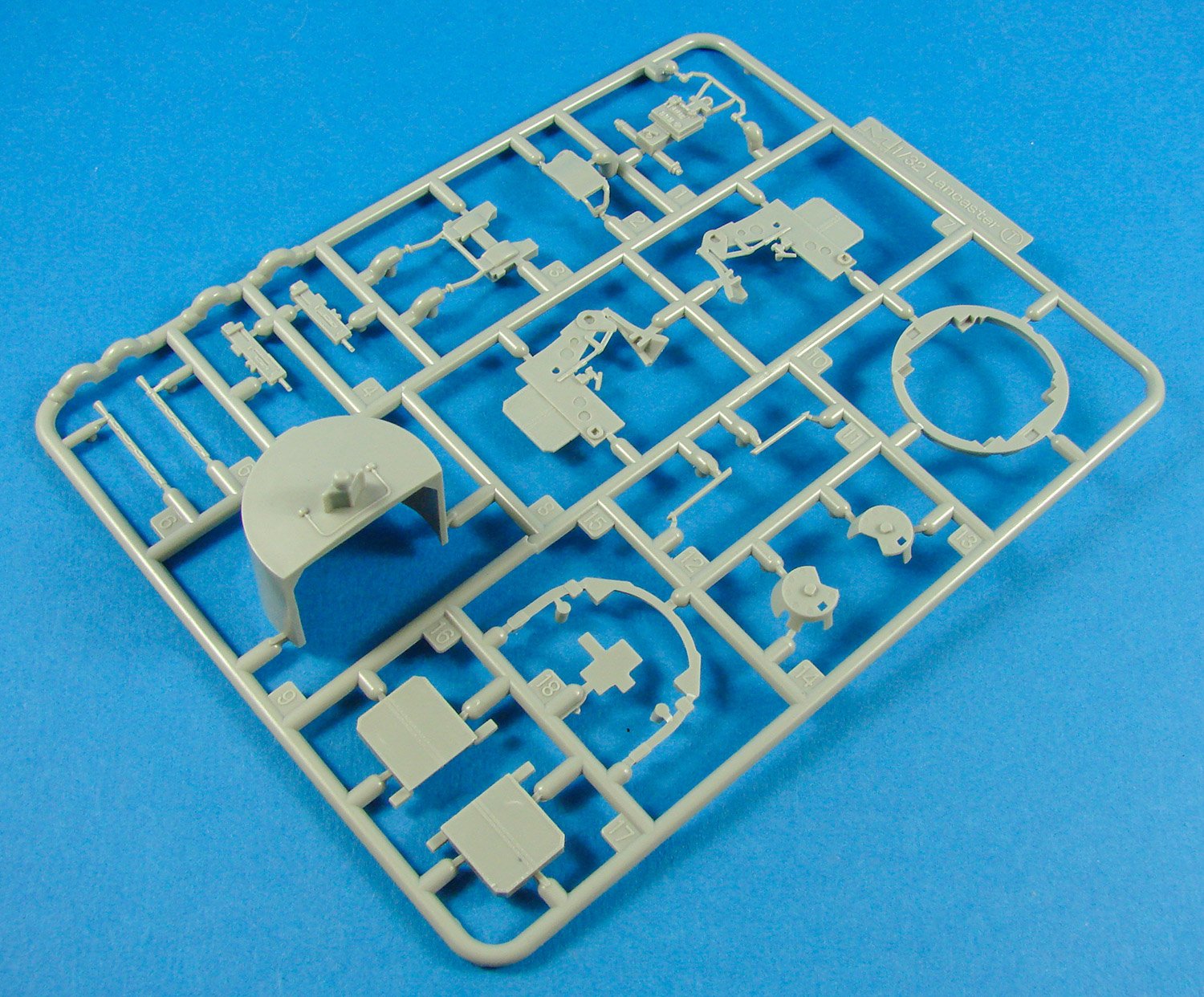
I know that there have already been 1:32 models of the V-1 produced before, but these have tended to be in resin, with the only injection kit being from Bronco, and in 1:35, which can be a little unpopular for aircraft modellers who craved this subject as a mainstream 1:32. Thankfully, Special Hobby recently announced such a kit and started to post some images of their new moulds and sprues on social media. As soon as this kit became available, yours truly asked Special Hobby if they’d send one out for review article, and here we are! Now, this is a relatively simple kit, as befits the subject, and it packaged into a standard Special Hobby lidded box with an nice image of a doomed V-1 crossing the white cliffs of Dover, being chased by a Gloster Meteor which will doubtless come and save the day. Inside the box, we have THREE light grey styrene sprues bagged within a single, re-sealable clear wallet, plus a small decal sheet and PE fret which are bagged together and slipped into the larger wallet. An instruction booklet completes the contents.Sprue A
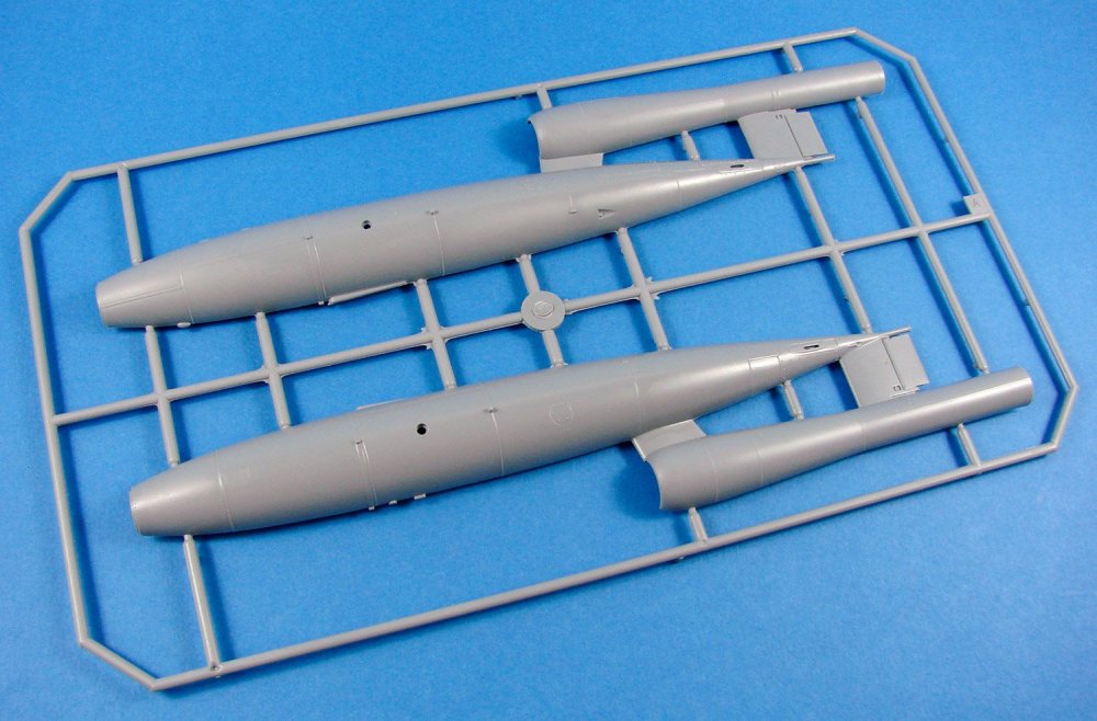
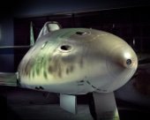
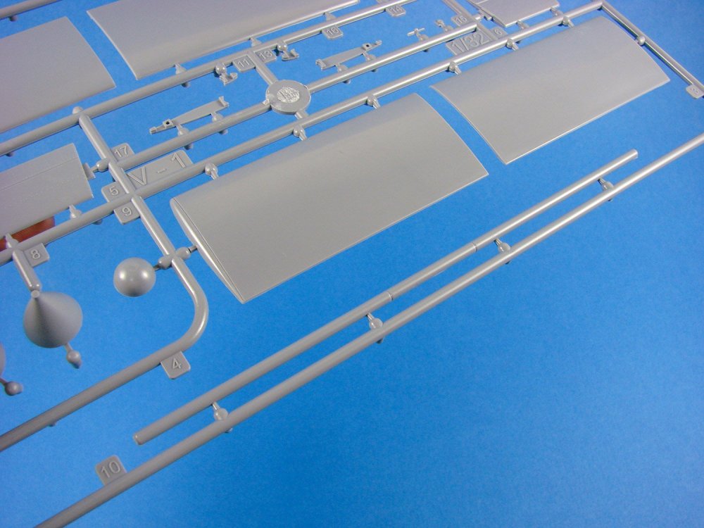
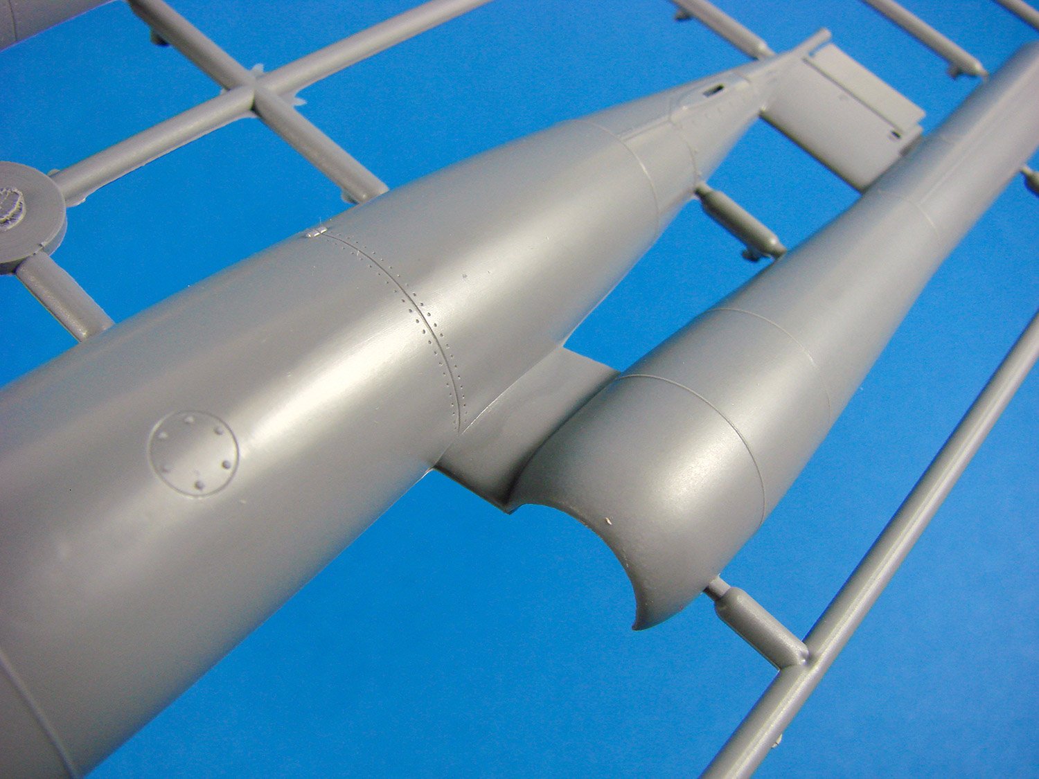
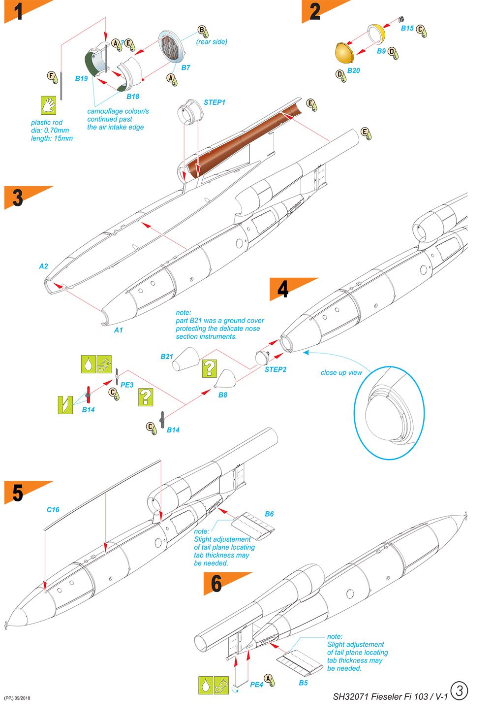
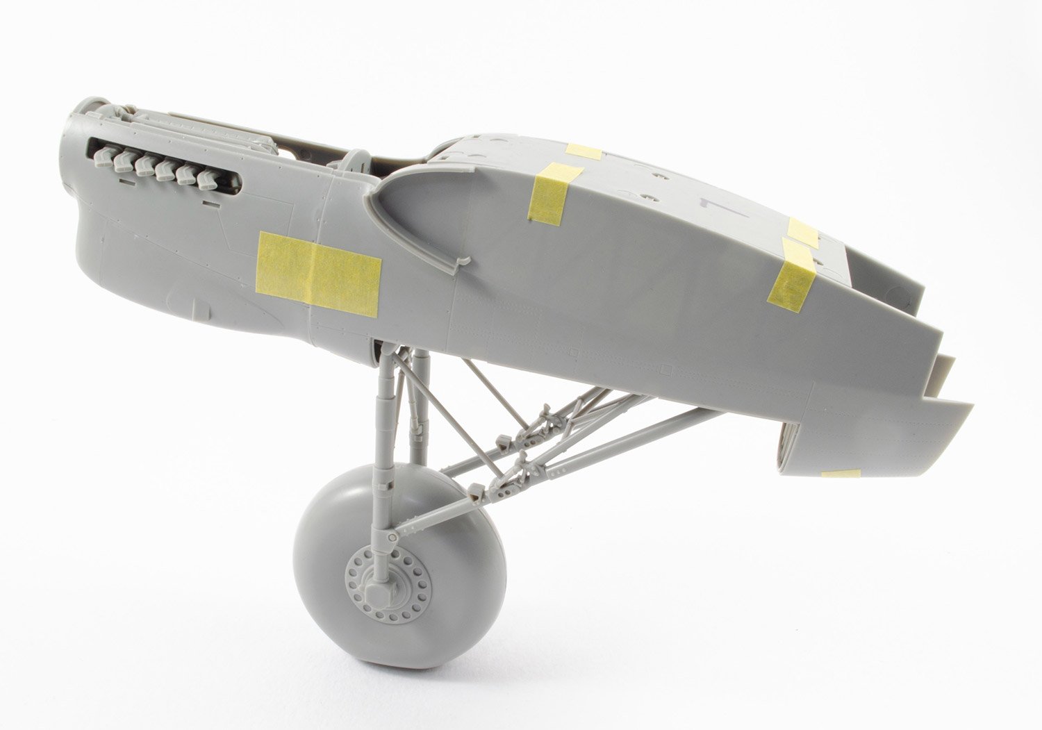
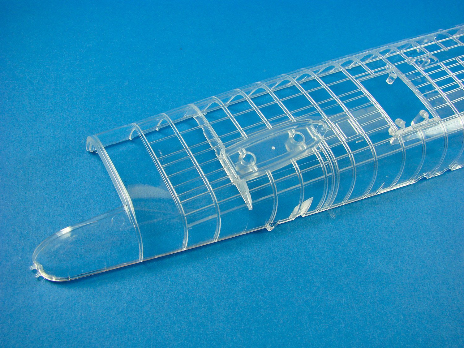
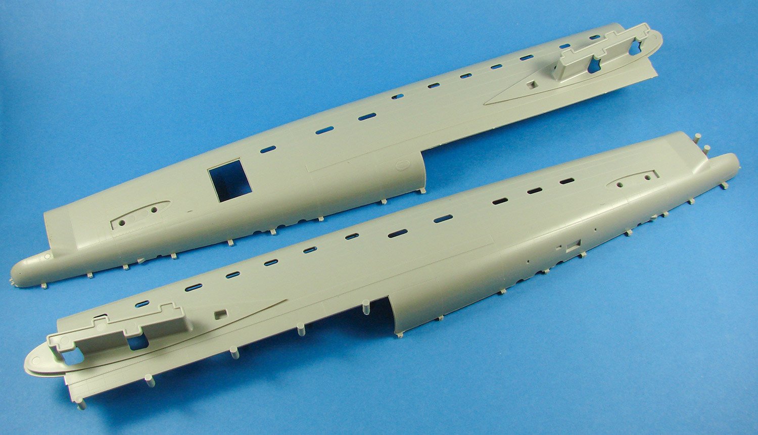
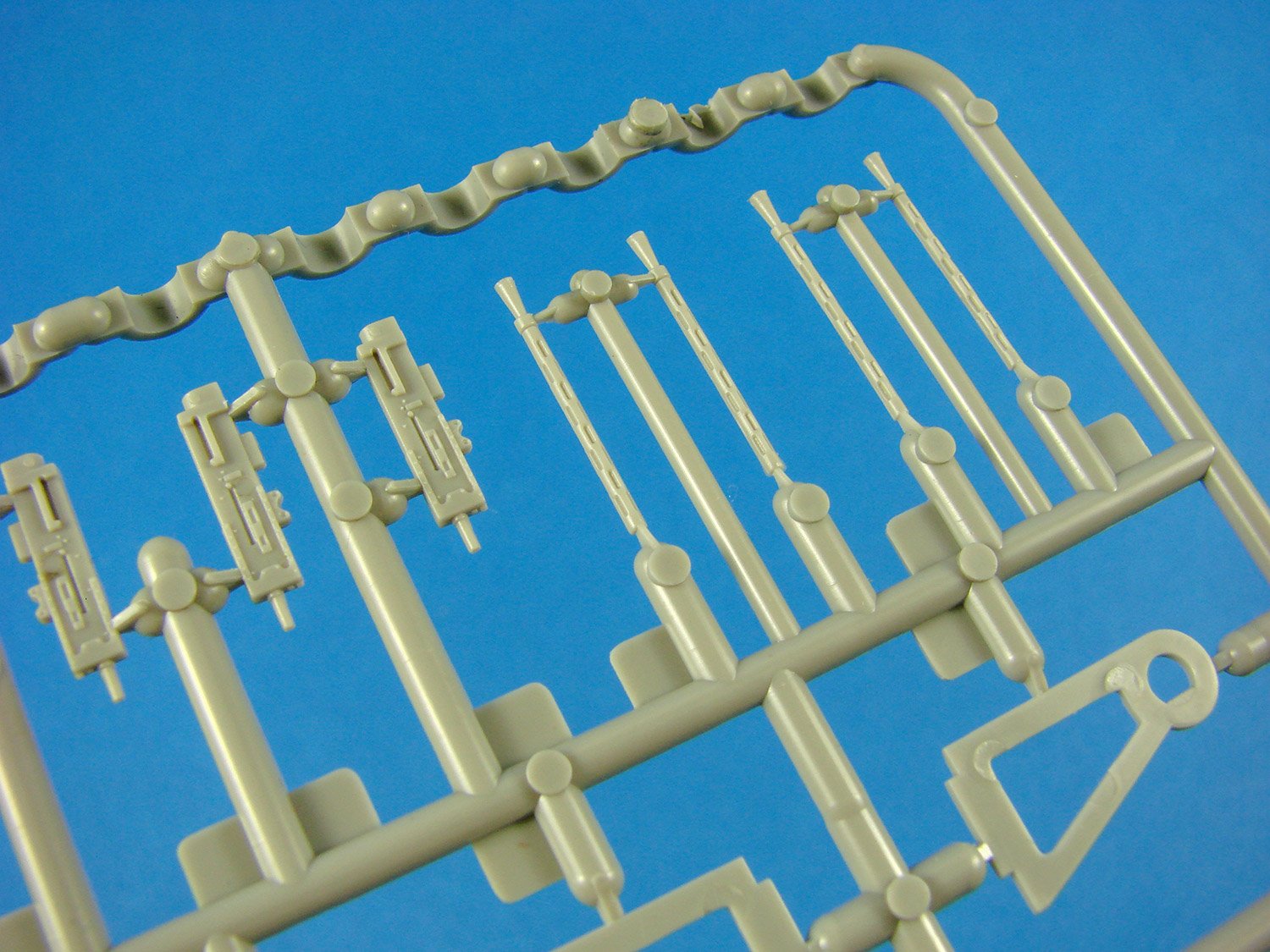
We are straight into the game with this first sprue, containing just two parts. These are fuselage left and right-side halves. Note that these are moulded with integral pulse jet engine and fin/rudder. As I said, this is a relatively simple model, but will still of course require some patience and care in removing all of the seams due to the integral pulse jet etc. The fuselage is moulded without any nose cone, for reasons we’ll soon see.

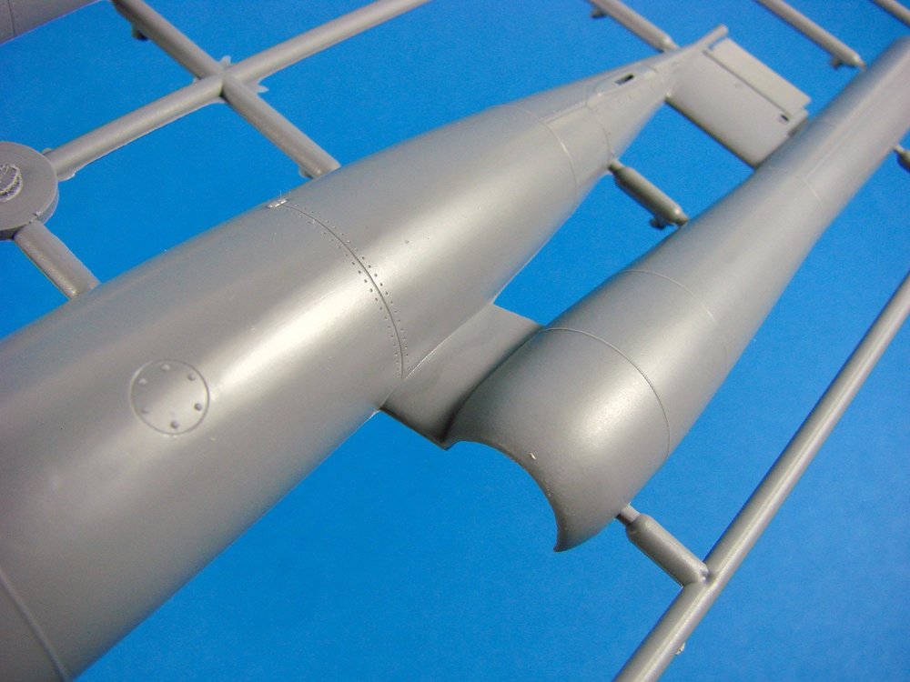
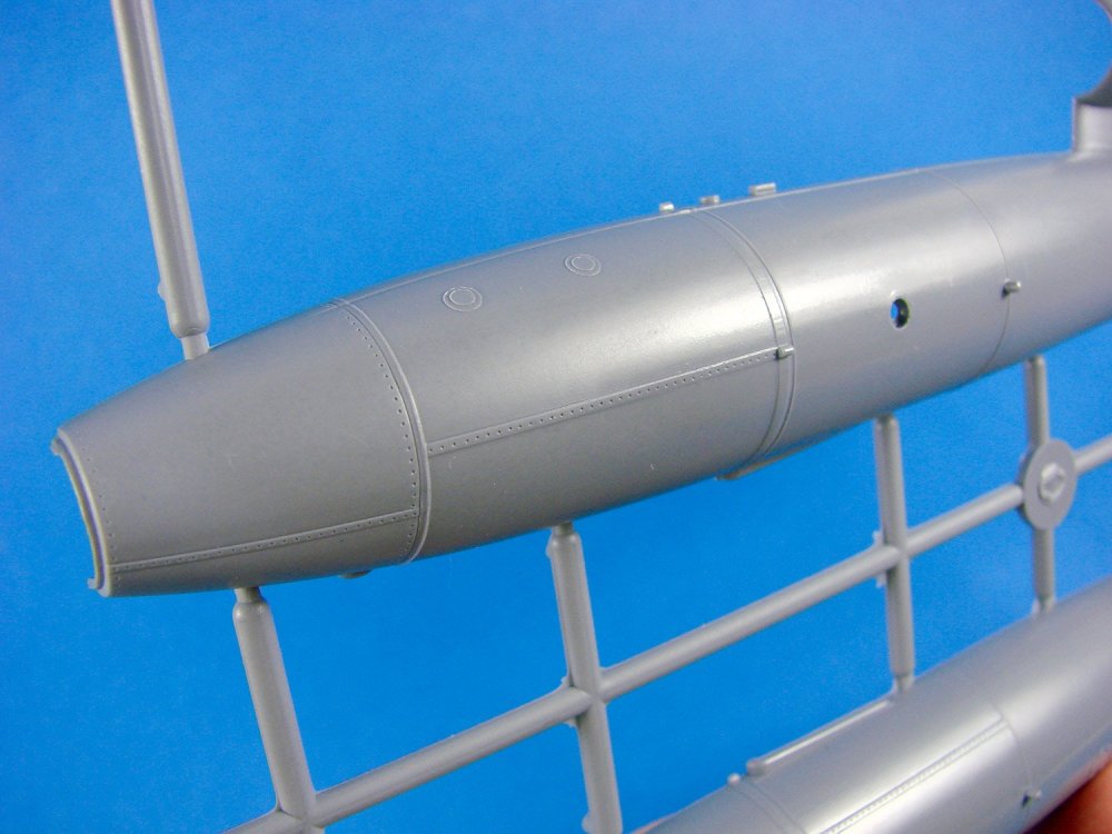
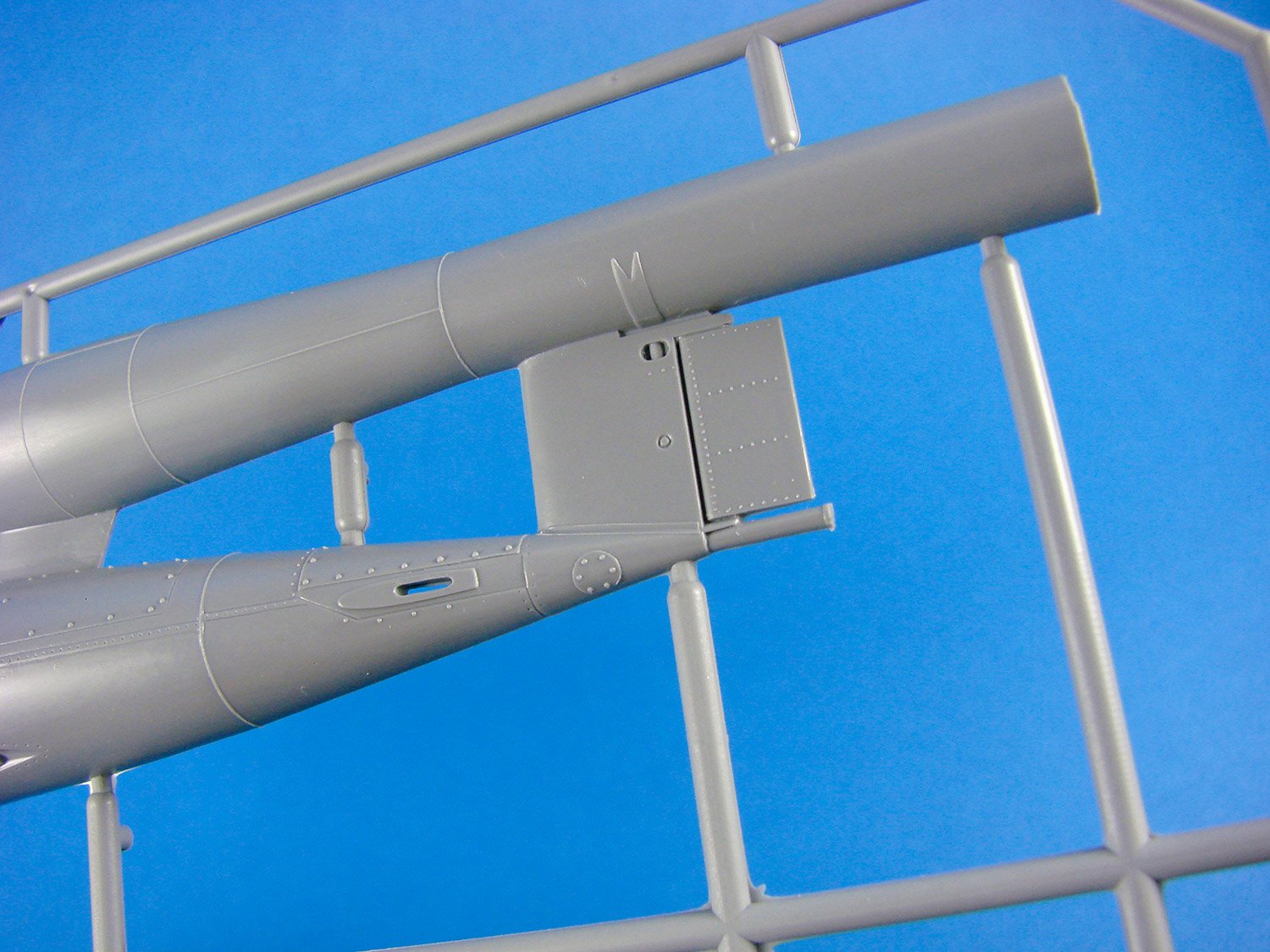
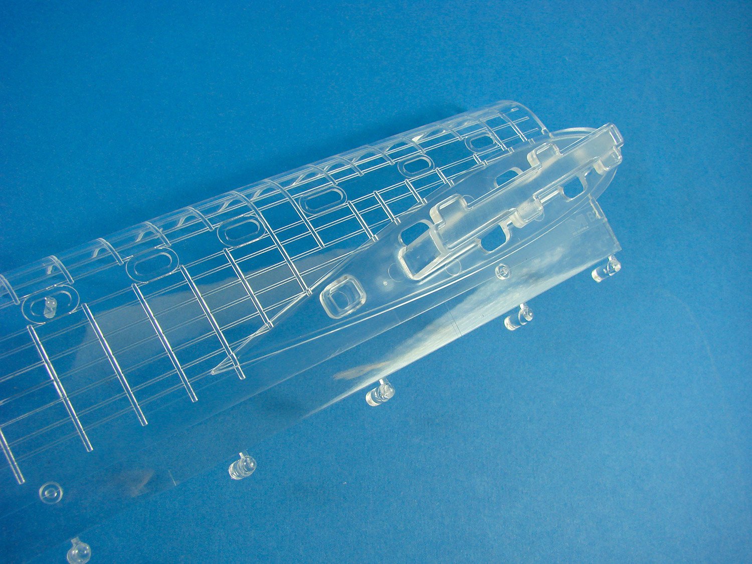
Externally, the fuselage detail looks very neat, with raised rivets and weld lines, where applicable, and other raised port access details etc. There are some engraved panel lines too, and raised strap detail with rivets, again where appropriate, and the whole effort does convey the single-use nature of the V-1, with nothing being too pretty and finished in terms of aerodynamics (those weld seams etc.). In all, I think Special Hobby have made a very nice job of recreating this terror weapon’s external appearance. Internally, there is of course zero detail, except for moulded locating rides for the pulse jet internals.
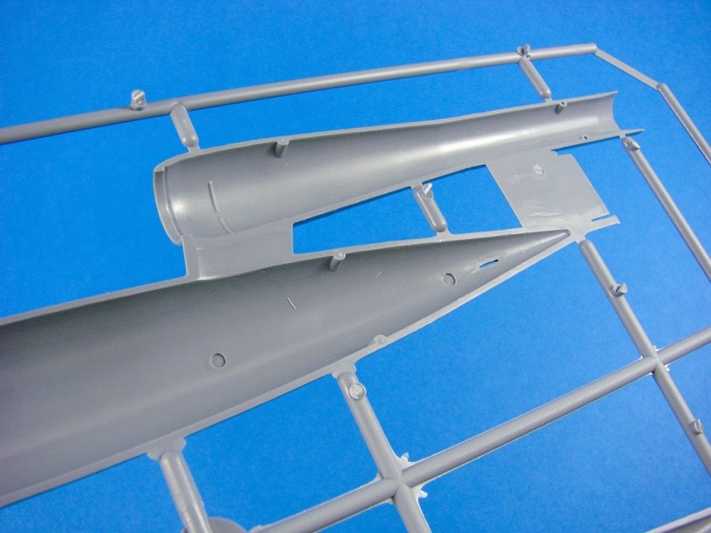
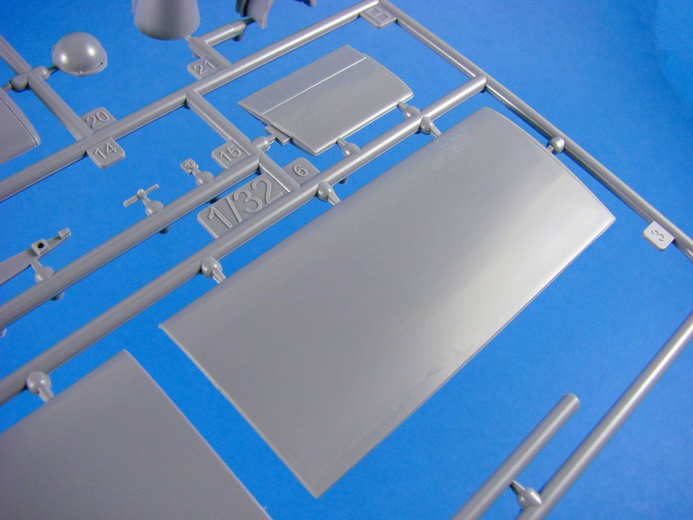
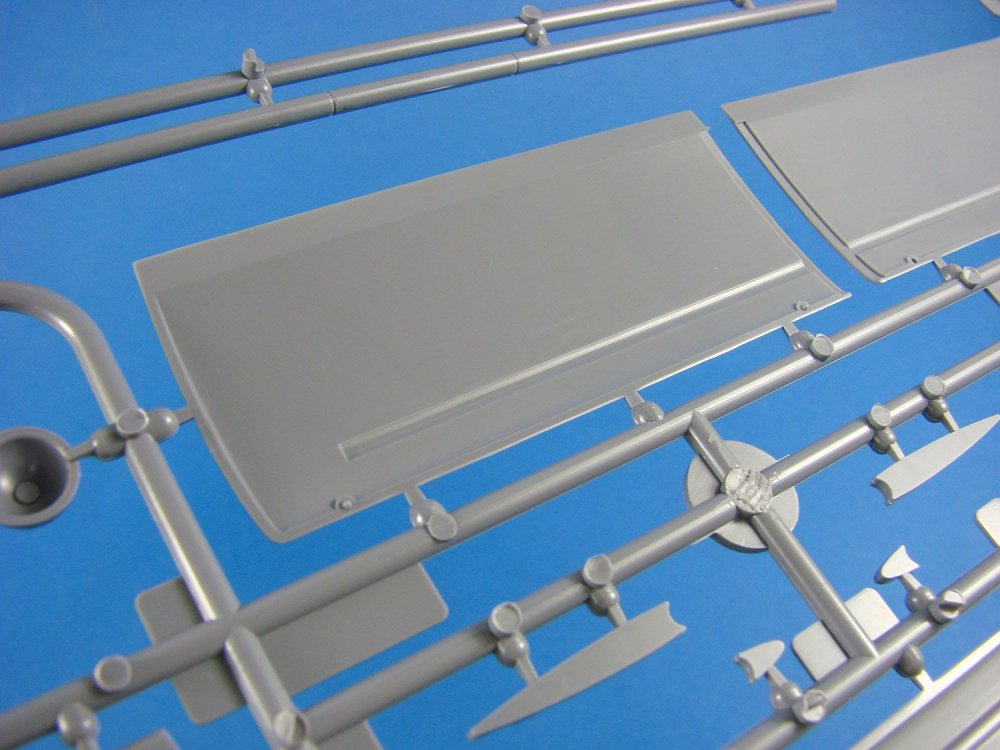
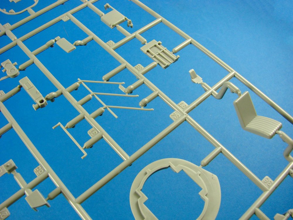
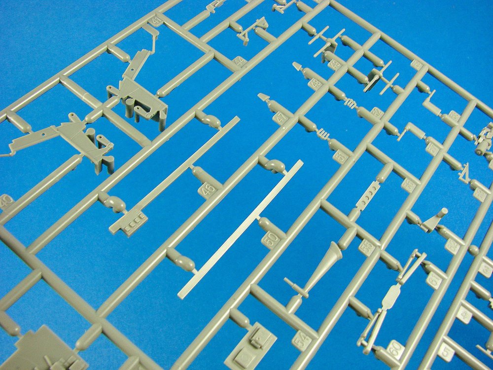
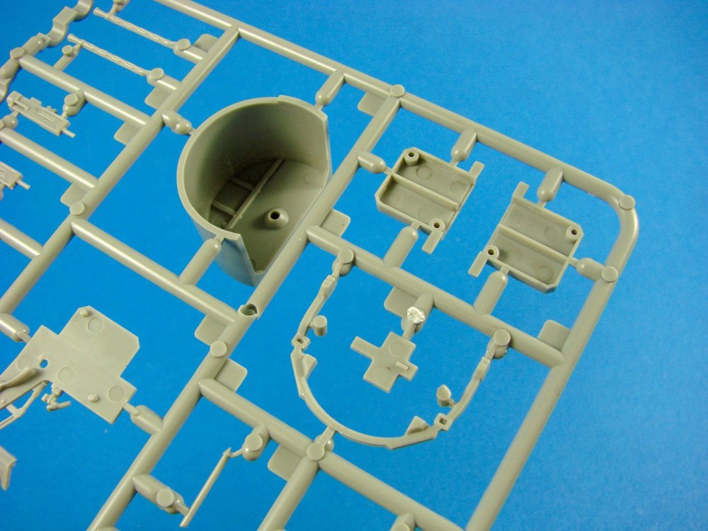
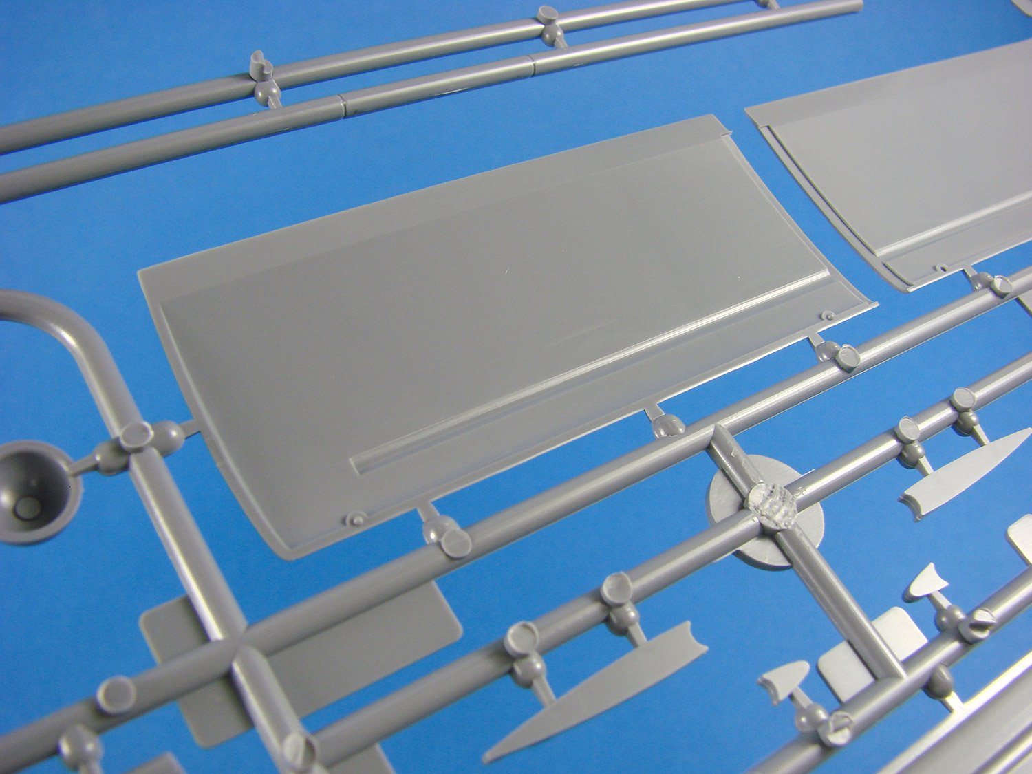
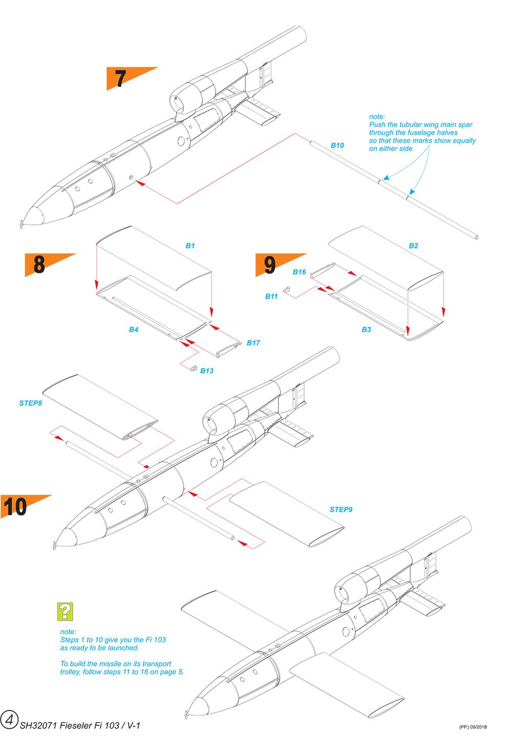
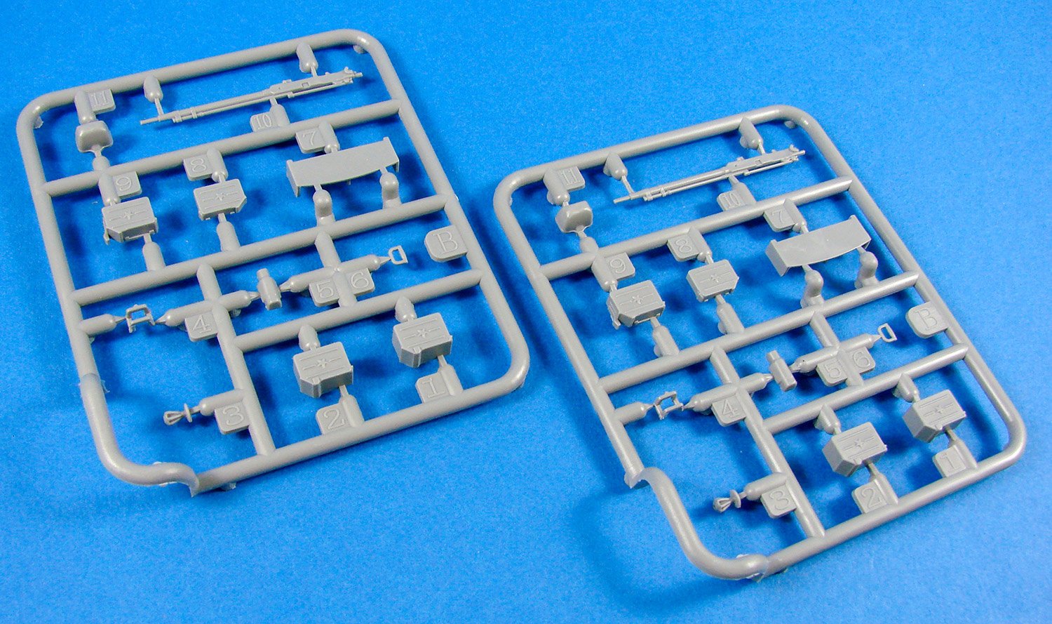
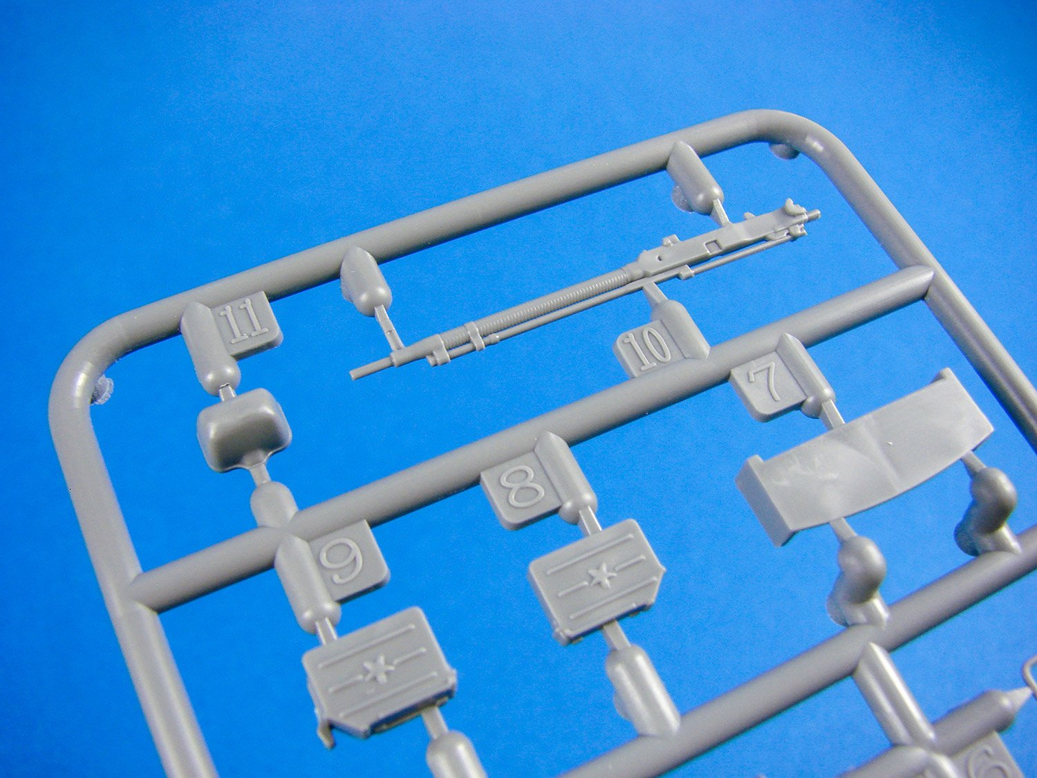
Sprue B
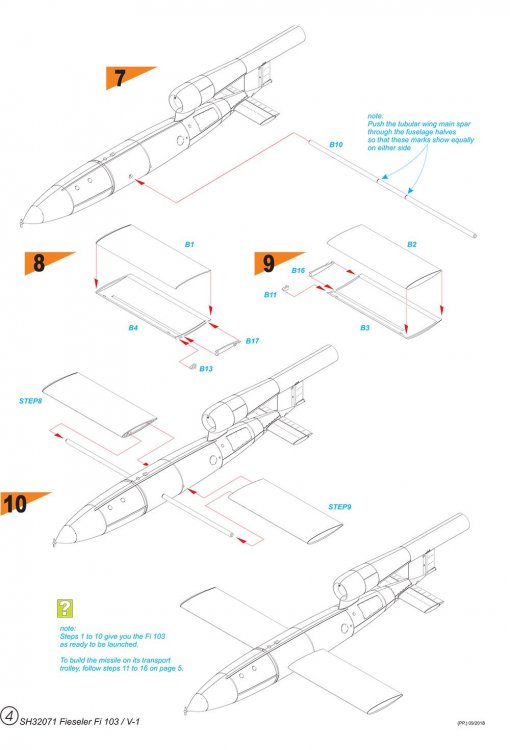
The wings of this model are a traditional affair with port and starboard upper and lower panels. Where this model differs though is that these wings can be posed either on or off the fuselage, depending on how you wish to finally display things. Each wing has a two-piece wing root insert, between which a tubular spar is fitted, as per the real V-1. This allows the modeller to slide the wings into position easily, using a moulded channel within each wing. Those wing panels are moulded with no surface detail which looks correct with photos of museum V-1 examples, but the wing tips are defined as separate as per the moulded items of the real thing. That main spar is also on this sprue, as are the single-piece port and starboard stabilisers, with integral elevators.
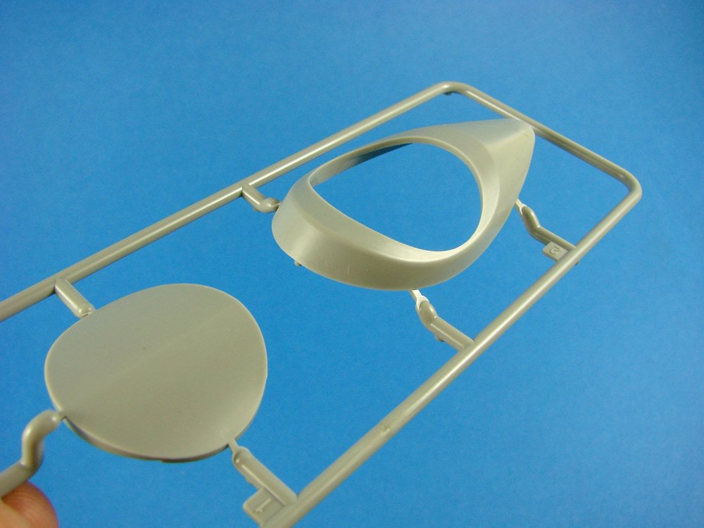
Now, the reason for the nose of the fuselage being separate is that there are three options for this area. These are for the uncovered nose instruments area, a protective cover for these instruments, and also the standard nose onto which the small impellor fits. The impellor is also included on this sprue, but a PE alternative is also provided.
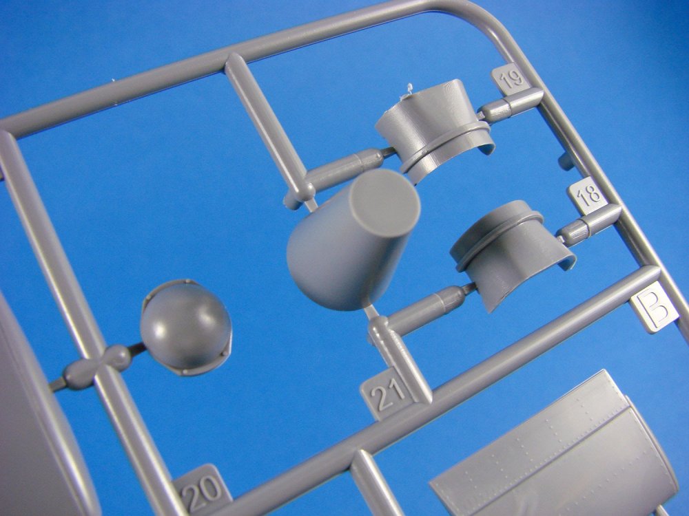
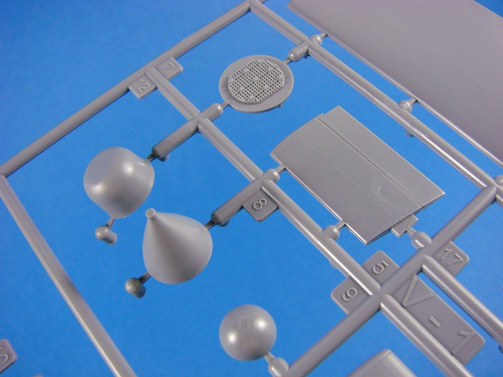
Also of note here are the internals for the pulsejet, including the intake screen. You will need to provide a small length of styrene rod for the intake area.
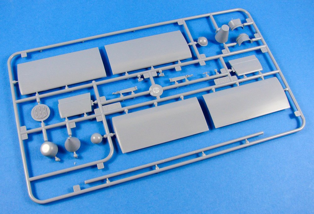
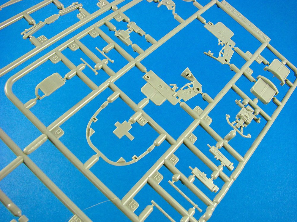
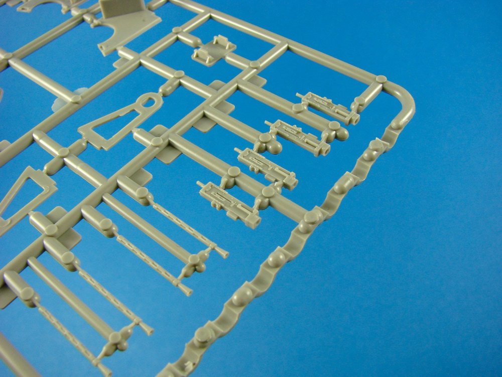
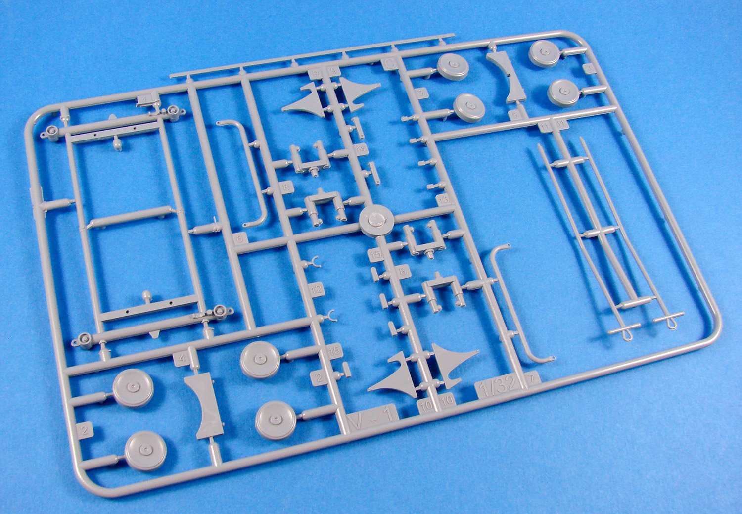
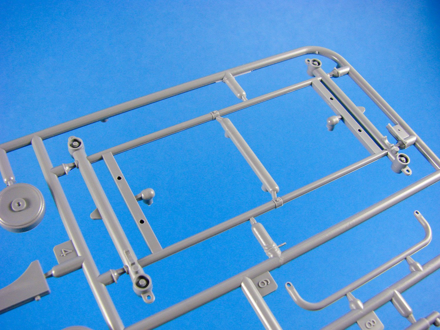
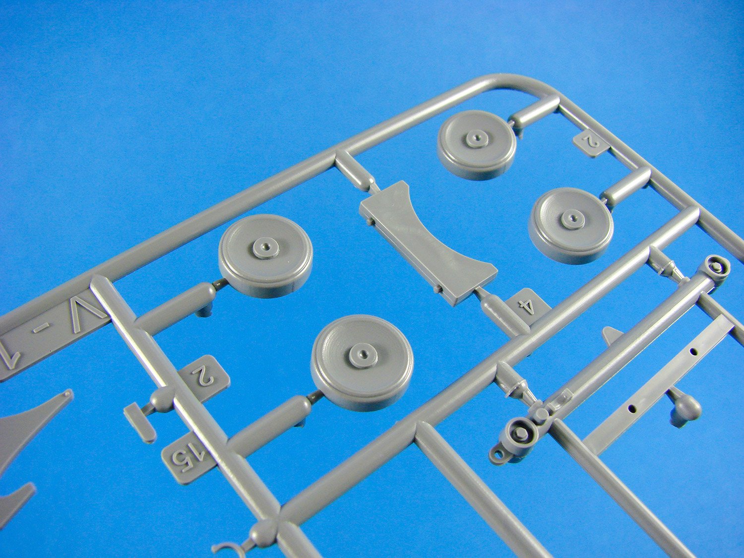
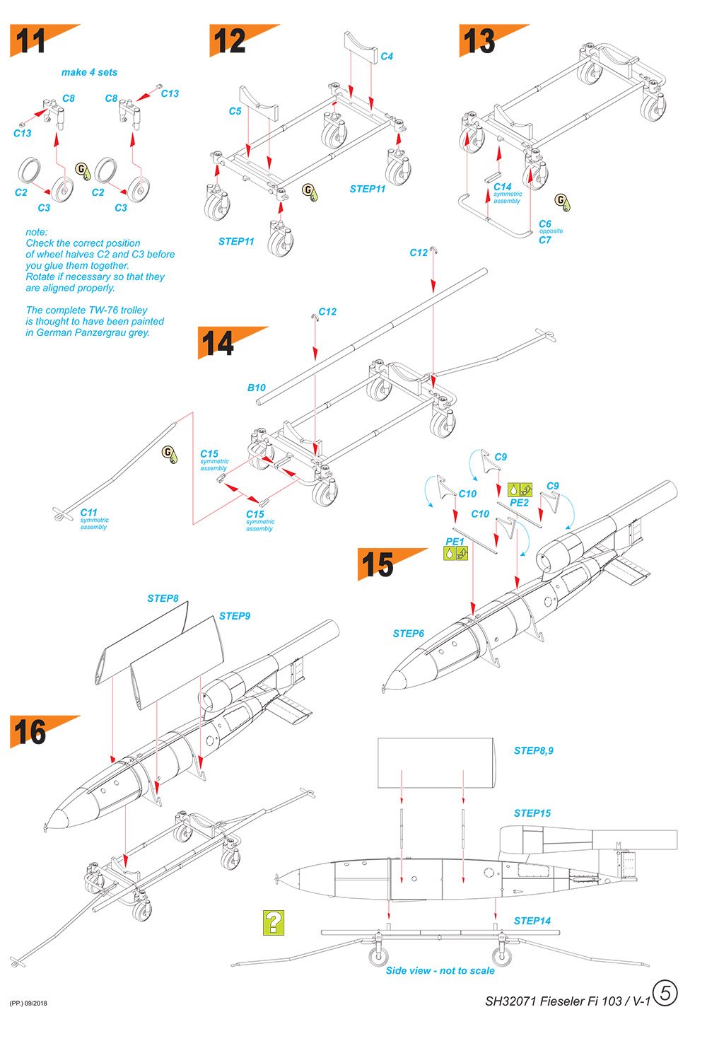
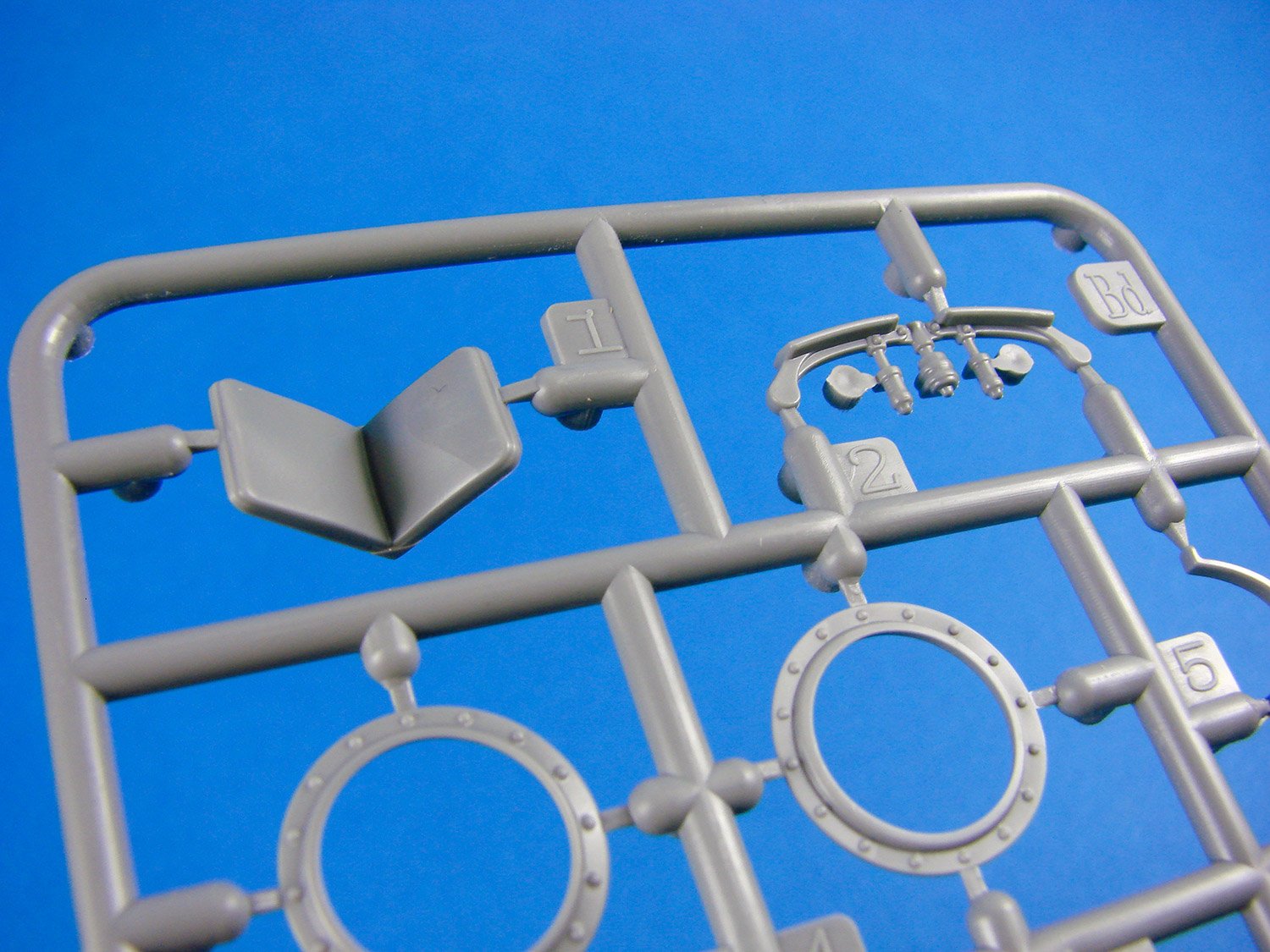
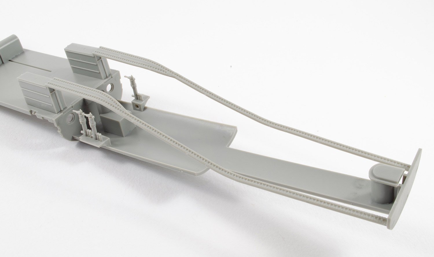
Sprue C
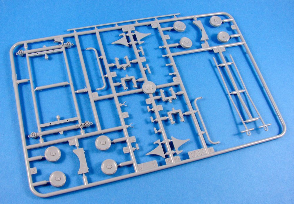
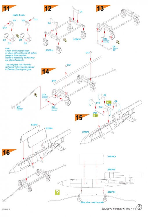
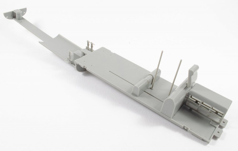
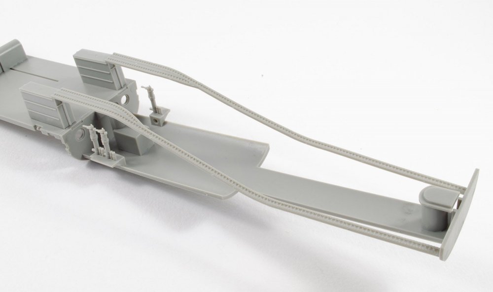
Apart from a fuselage stiffening strake which seems to have been added to the outside of this sprue as some sort of afterthought, the rest of this last sprue concerns the transportation trolley for the V-1. The main frame itself is moulded as a single piece and the wheels are moulded as halves which insert to their brackets before being added to the main frame. To hold the weapon in place, some shaped standoff formers are provided. The trolley also has a drag handle and tow handle, as well as a facility to hold the wing spar for the V-1, prior to fitting the wings. Extra trolley formers are designed to hold the wings in place before fitting.
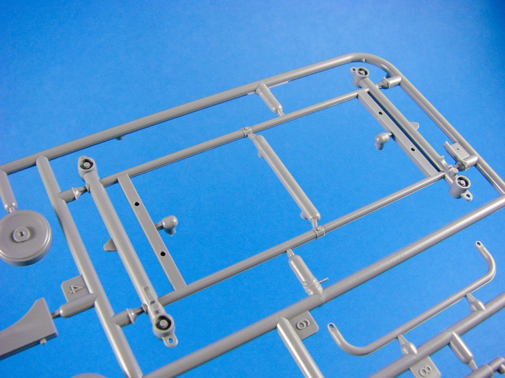
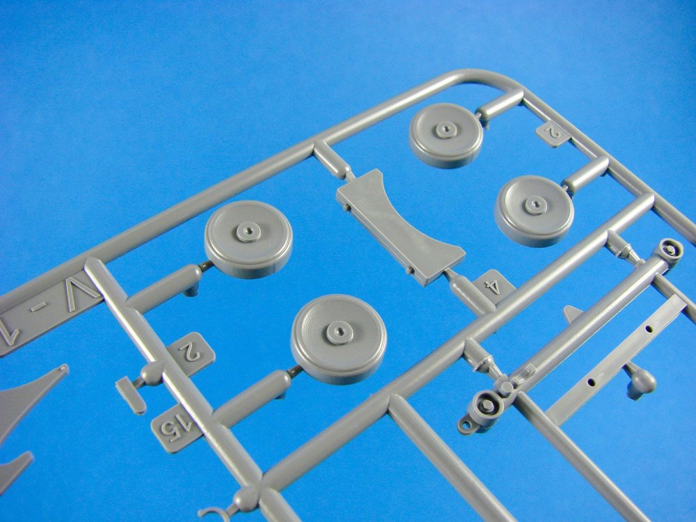
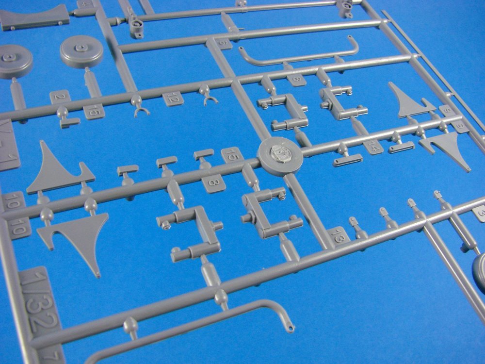
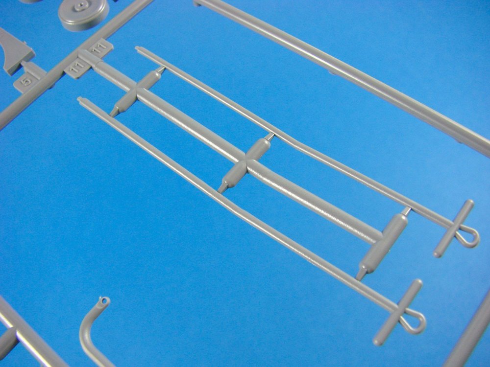
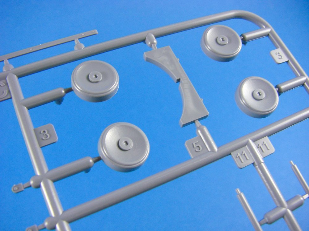
Photo Etch
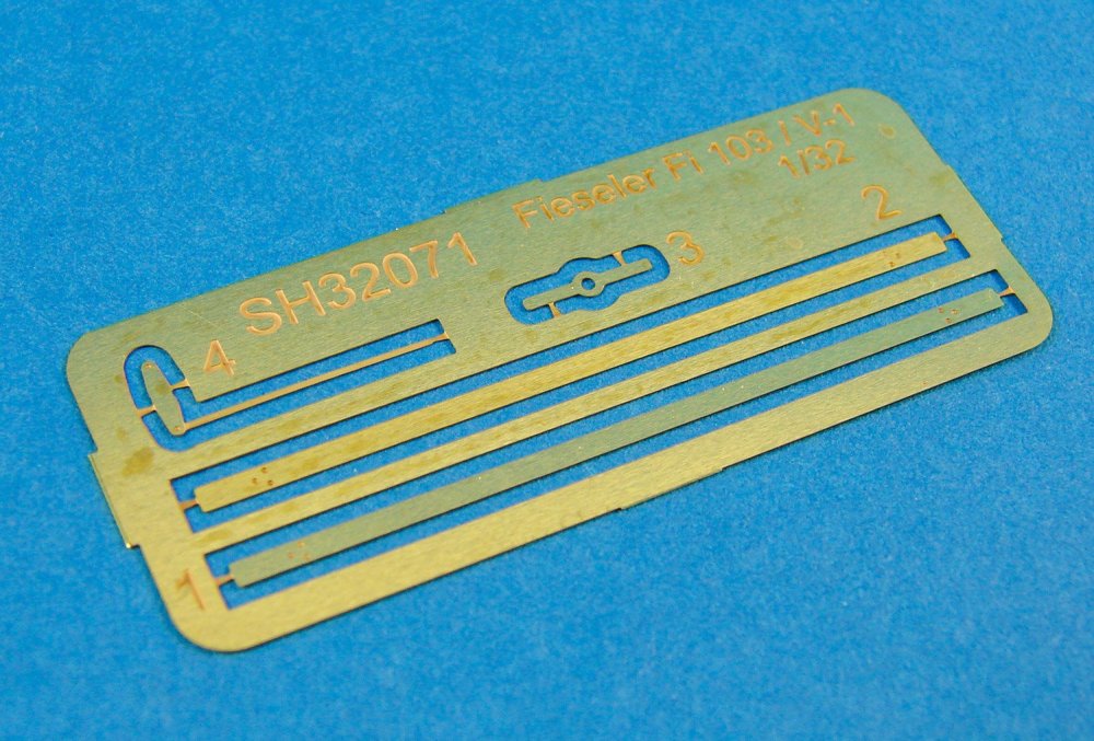
Only four parts are included here. These are for the two straps that tie the fuselage down onto the formers of the trolley, a PE impellor alternative, and a rudder actuator. Nicely made, these should present no problem in fitting.
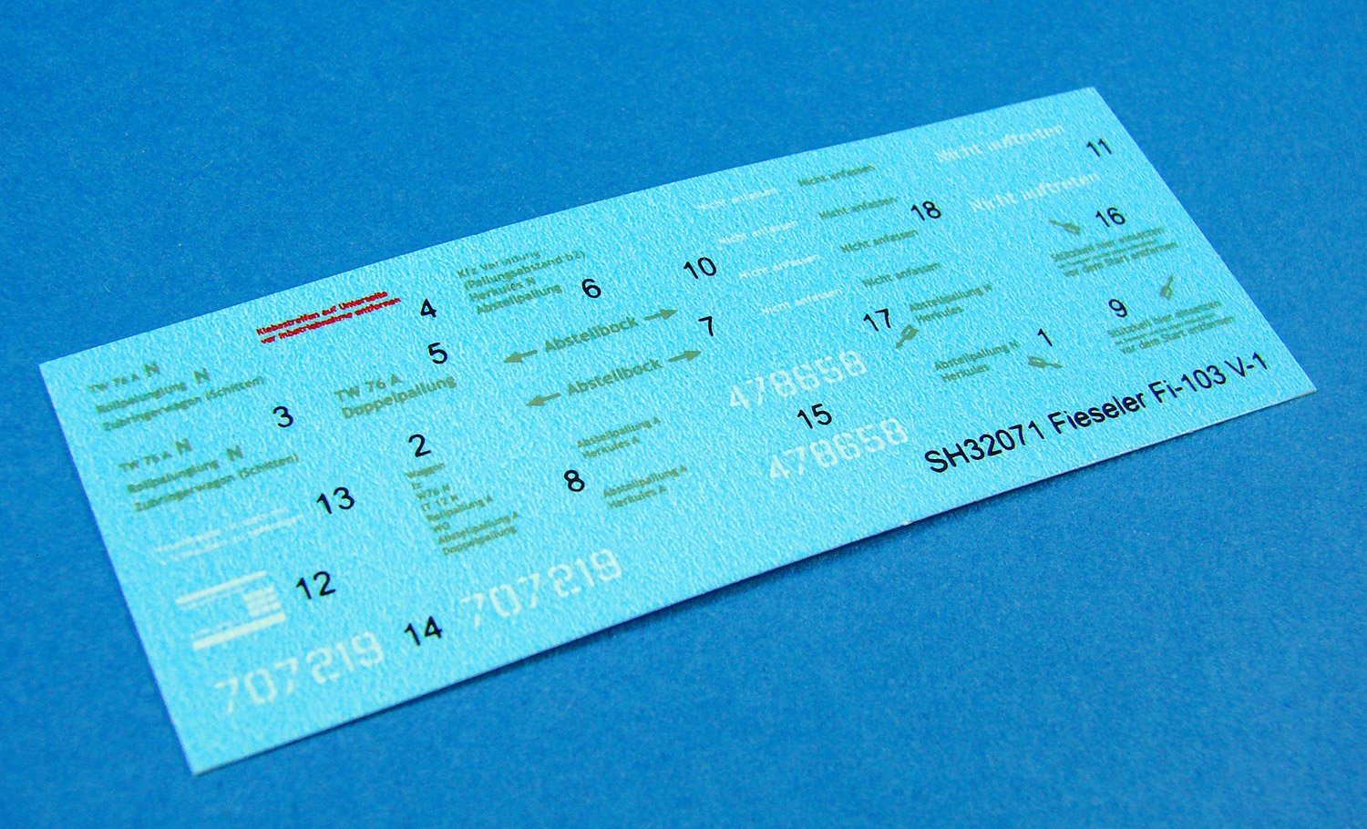
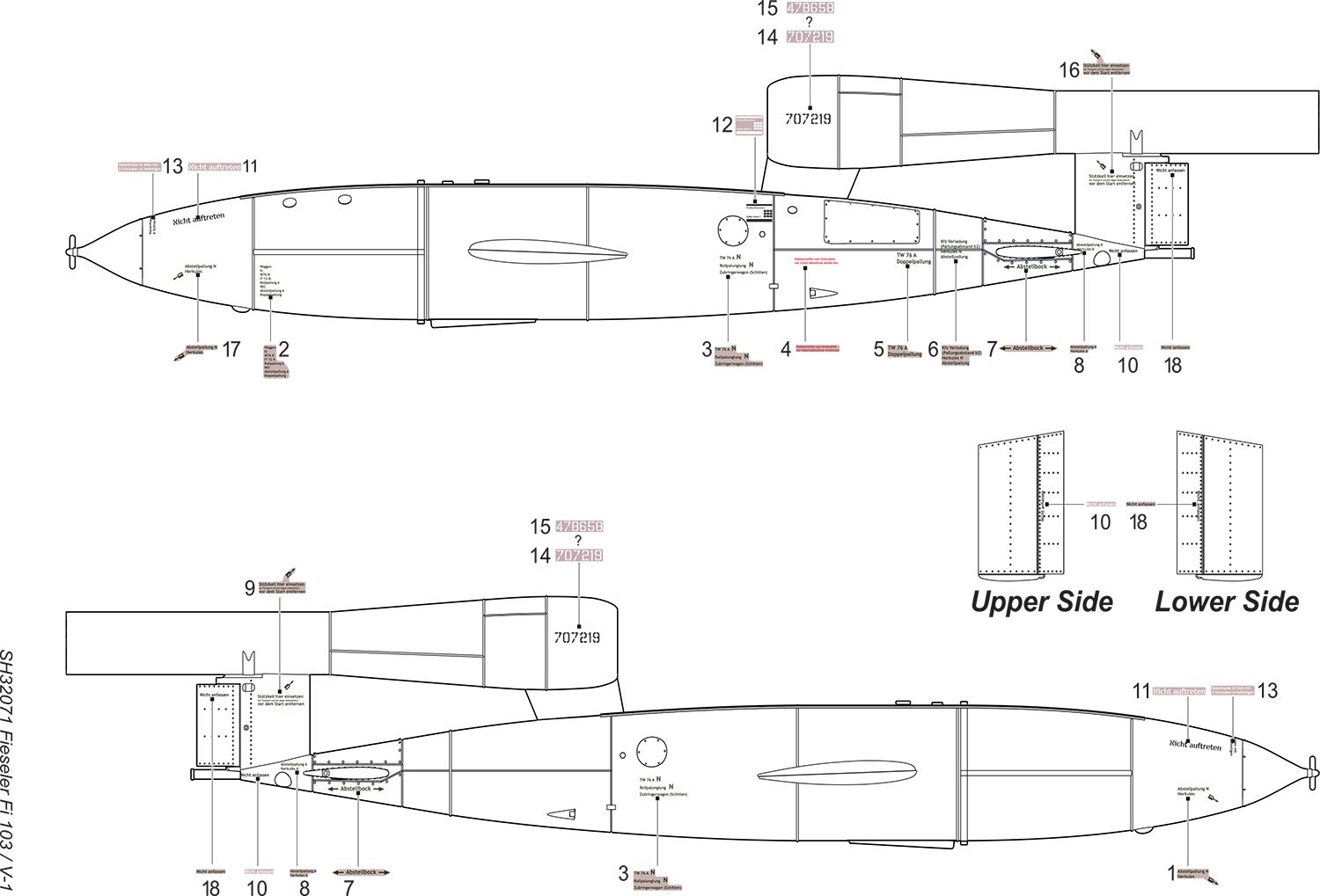
Decals
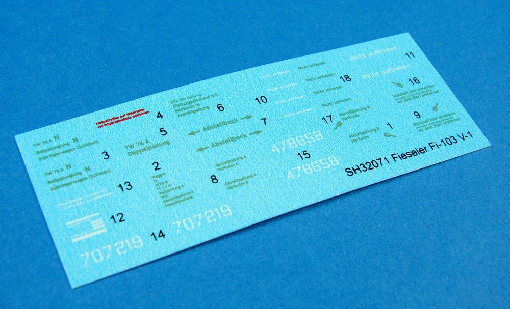
Just because this is a flying bomb doesn’t mean that there’s no decals! In fact, the Germans like to add stencils to just about anything, and this is no exception. Here you’ll find a whole suite of various stencils to adorn the V-1, including serials etc.
Printing is good, with minimal carrier film and thin ink layers. Registration isn’t an issue here as all decals are printed in single colours.
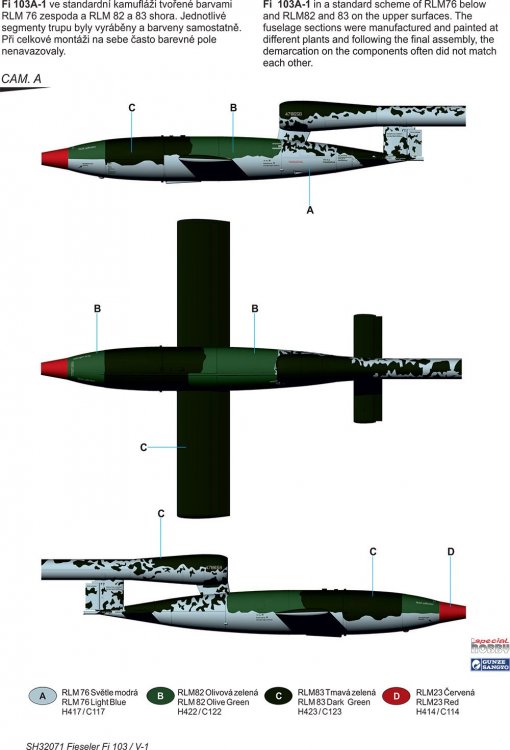
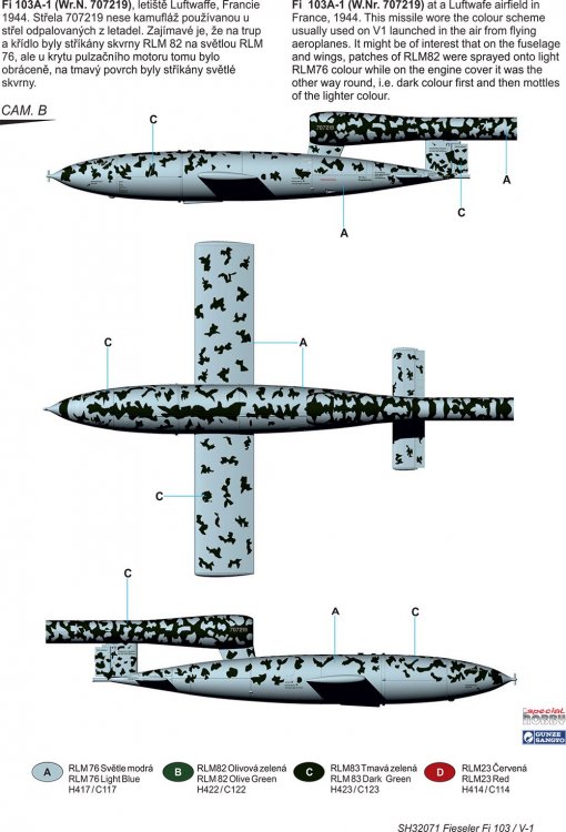
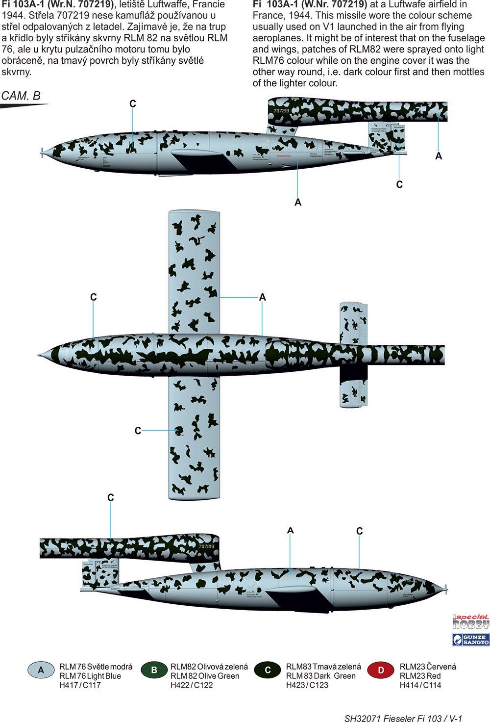
The schemes given for this release are:
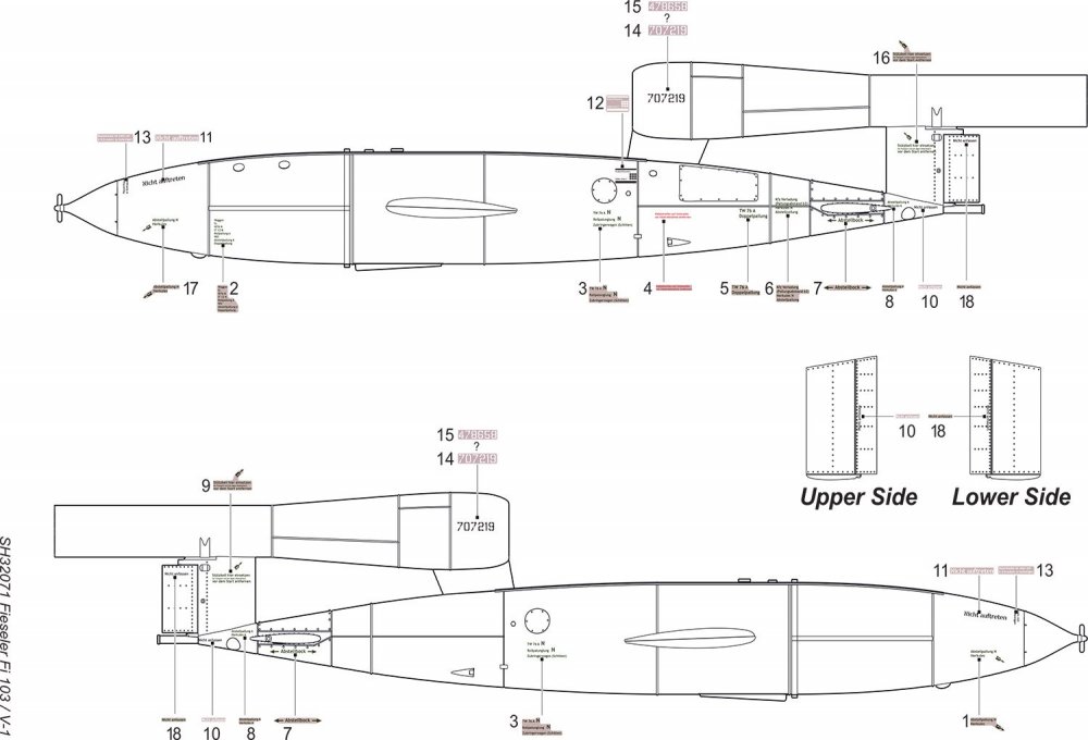
Instructions

This instruction booklet starts with a brief history of the V-1, and then into a handy parts map on the second page. Construction is broken down into 16 easy to follow stages, with some colour to denote PE etc. and clear annotation. Paint references are provided throughout and colour codes are supplied for Gunze paints.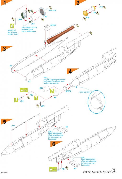
Conclusion
A very simple but superbly executed subject which is nicely designed and expertly moulded. The only real effort you need to make in construction is the removal of the fuselage seam. The options to build this with or without wings, and the additional trolley, certainly adds to your final display options of what is essentially just a bomb with wings. This is also a relatively inexpensive kit and should be a nice little mojo-restorer to those jaded with long, arduous and aftermarket-filled projects that bog us down from time to time. Get them while they’re hot!My sincere thanks to Special Hobby for speedily getting this new release out for review here on Large Scale Modeller. To purchase, click the link at the top of the article.

-
3
-
-
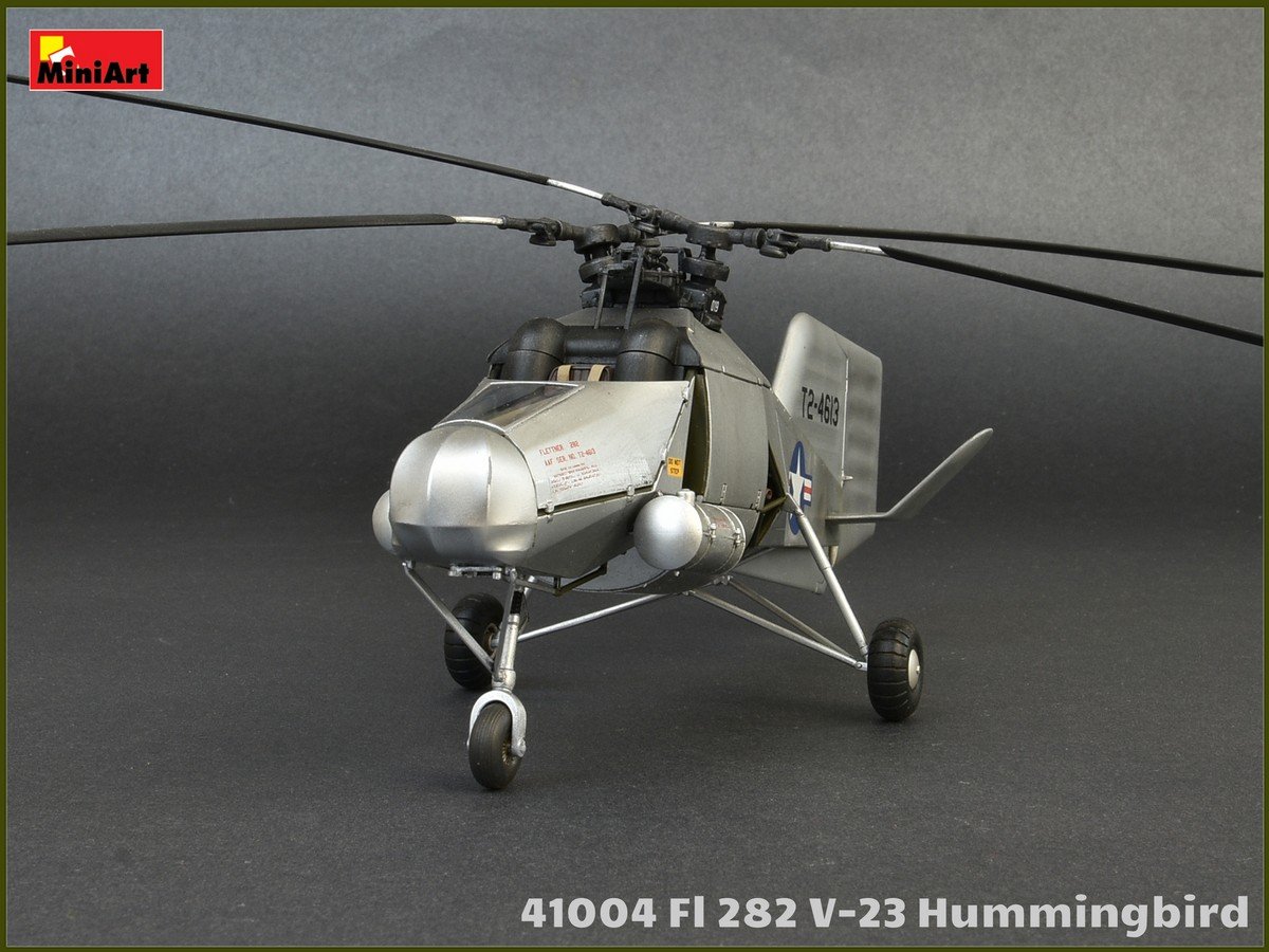
1/35 Flettner Fl 282V-23 Hummingbird
Aircraft Miniatures Series
MiniArt
Catalogue # 41004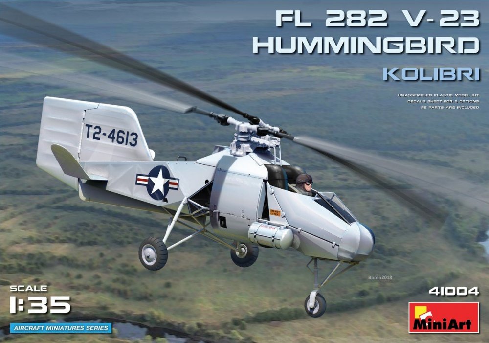
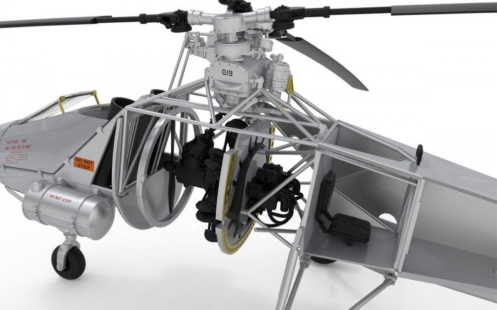
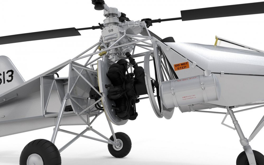
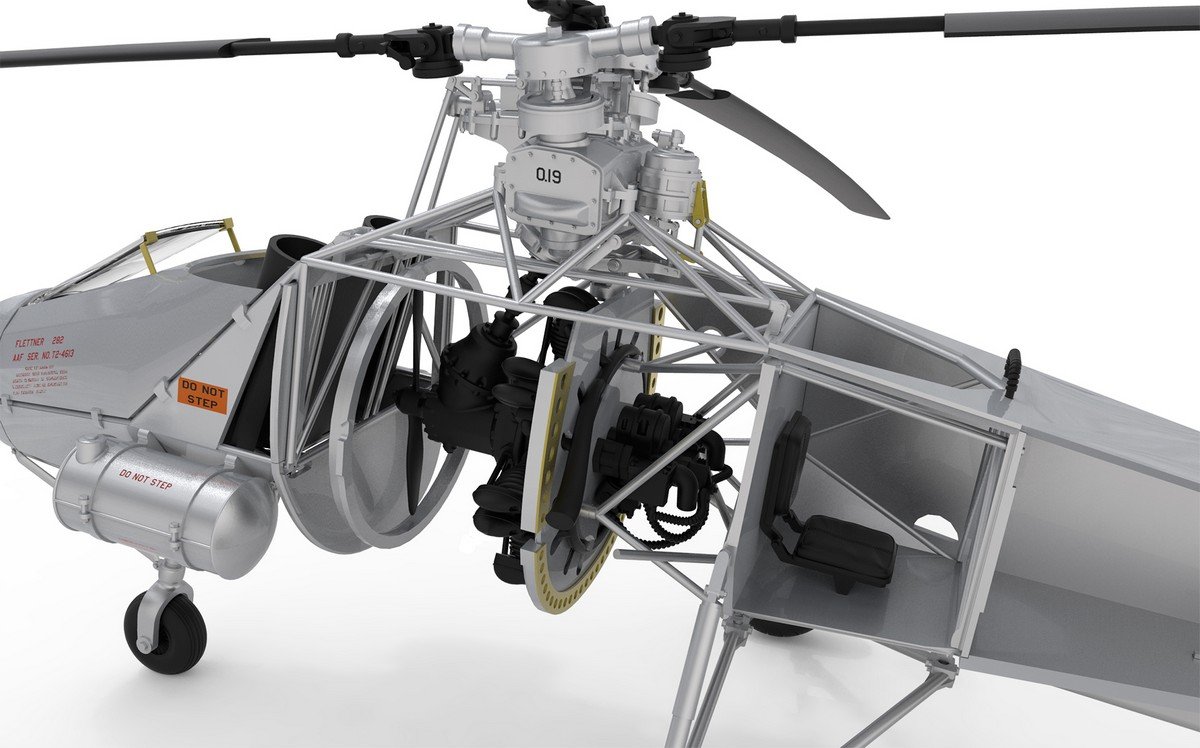
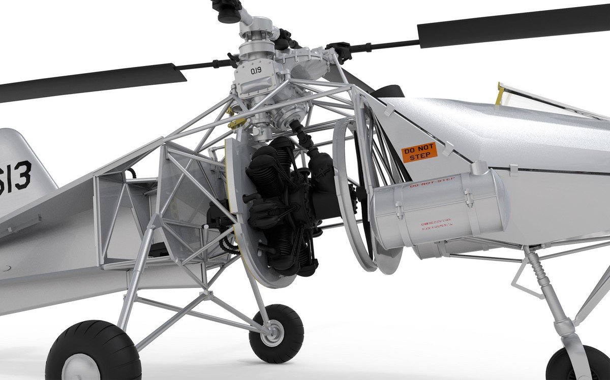
The Flettner Fl 282 Kolibri ("Hummingbird") is an intermeshing rotor helicopter, or synchropter, produced by Anton Flettner of Germany. According to Yves Le Bec, the Flettner Fl 282 was the world's first series production helicopter. though other writers claim the same for the Focke-Achgelis Fa 223. Flettner’s Fl 282 Kolibri was an improved version of the Flettner Fl 265 announced in July 1940, which pioneered the same intermeshing rotor configuration that the Kolibri used. It had a 7.7 litre displacement, seven-cylinder Siemens-Halske Sh 14 radial engine of 150-160 hp mounted in the centre of the fuselage, with a transmission mounted on the front of the engine from which a drive shaft ran to an upper gearbox, which then split the power to a pair of opposite-rotation drive shafts to turn the rotors. The Sh 14 engine was a tried-and-true design that only required servicing every 400 hours, as opposed to the nearly 27 litre displacement, nine-cylinder BMW/Bramo Fafnir 750hp radial engine powering the larger Focke-Achgelis Fa 223 helicopter, whose outdated design required maintenance every 25 hours. The Fl 282's fuselage was constructed from steel tube covered with doped fabric, and it was fitted with a fixed tricycle undercarriage.
The German Navy was impressed with the Kolibri and wanted to evaluate it for submarine spotting duties, ordering an initial 15 examples, to be followed by 30 production models. Flight testing of the first two prototypes was carried out through 1941, including repeated take-offs and landings from a pad mounted on the German cruiser Köln. The first two "A" series prototypes had enclosed cockpits; all subsequent examples had open cockpits and were designated "B" series. In case of an engine failure, the switch from helicopter to autorotation was automatic. Good handling in bad weather led the German Air Ministry to issue a contract in 1944 to BMW to produce 1,000 units. However, the company's Munich plant was destroyed by Allied bombing raids after producing just 24 machines. Towards the end of World War II most of the surviving Fl 282s were stationed at Rangsdorf, in their role as artillery spotters, but gradually fell victim to Soviet fighters and anti-aircraft fire. A total of 24 machines were built.
Edit courtesy of WikipediaThe kit

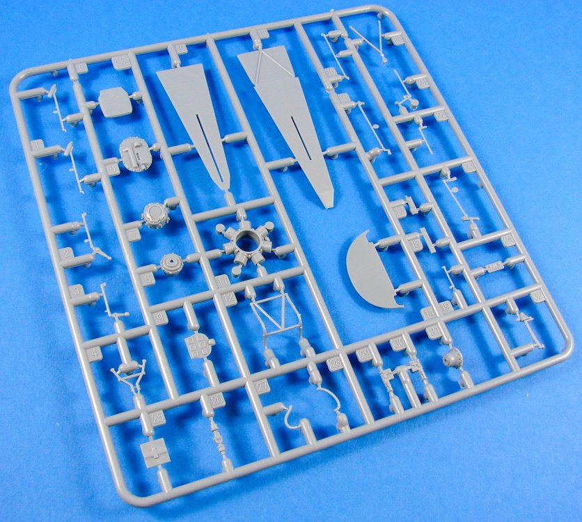
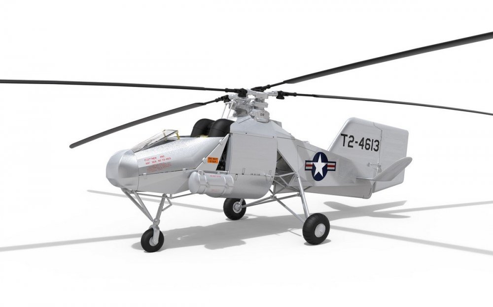
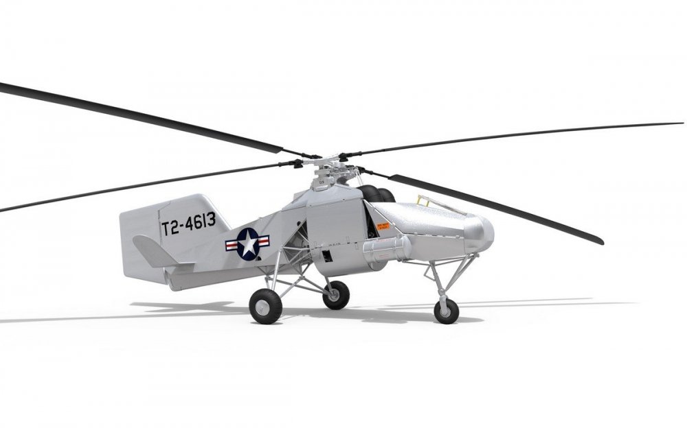
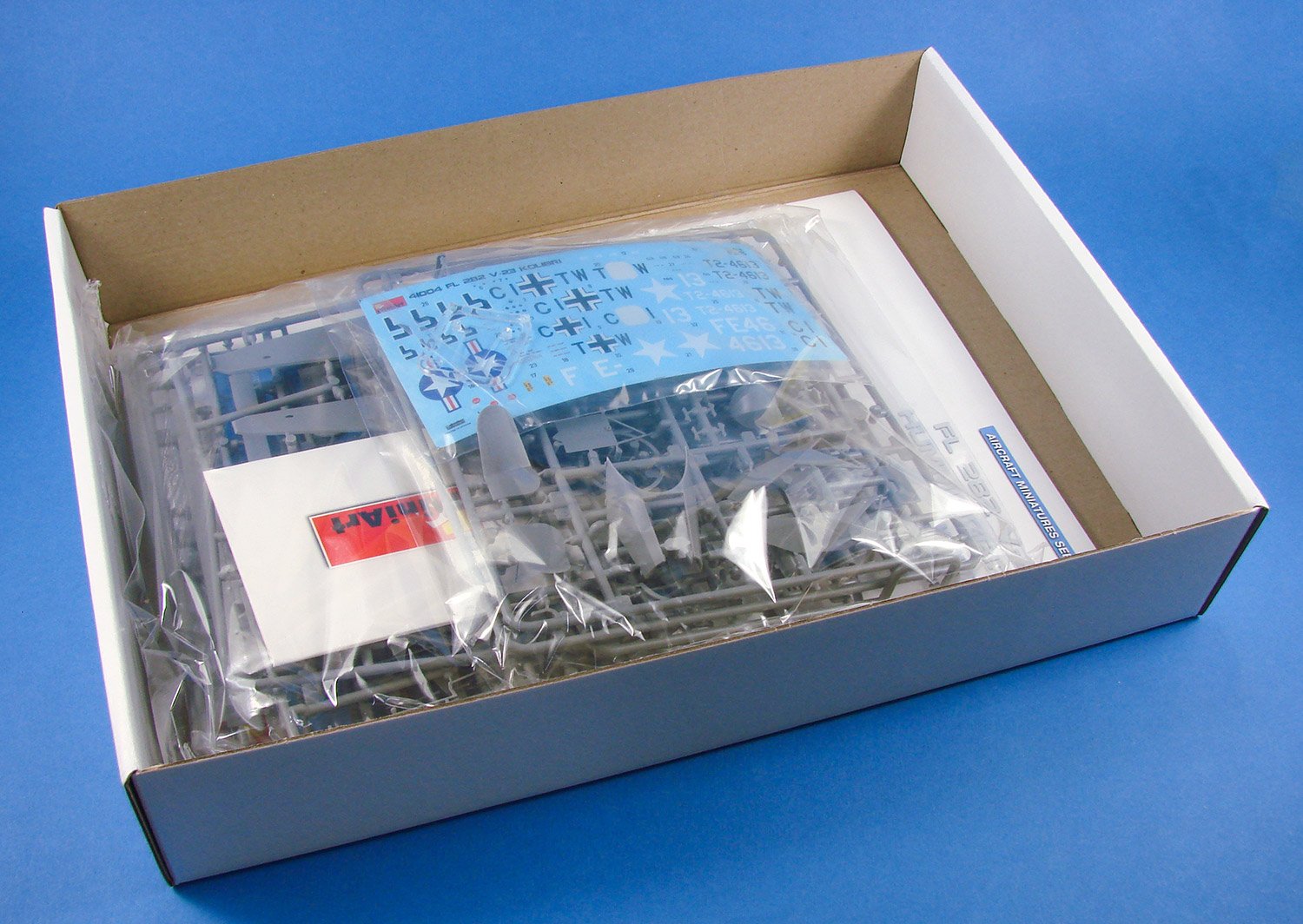
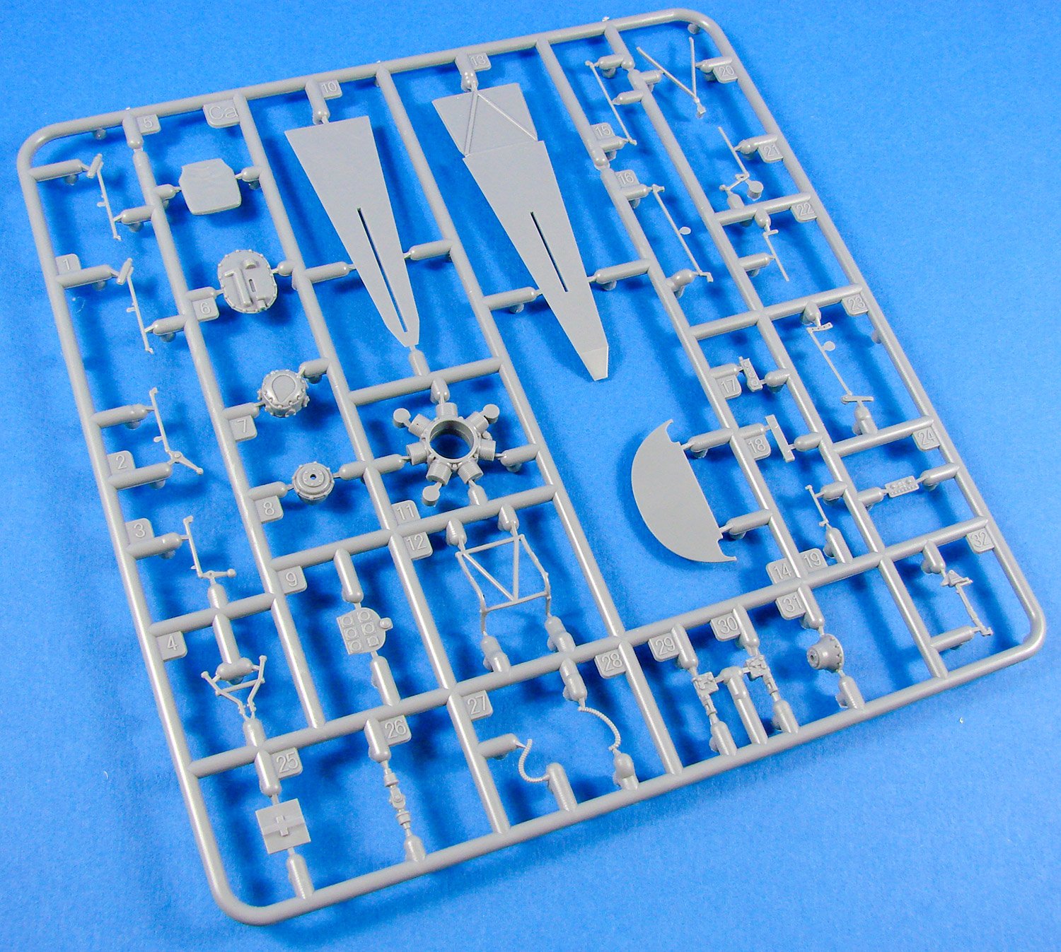
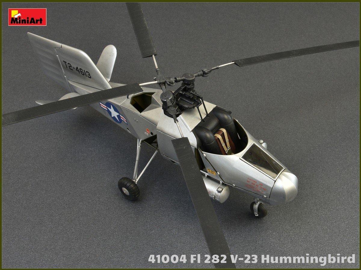
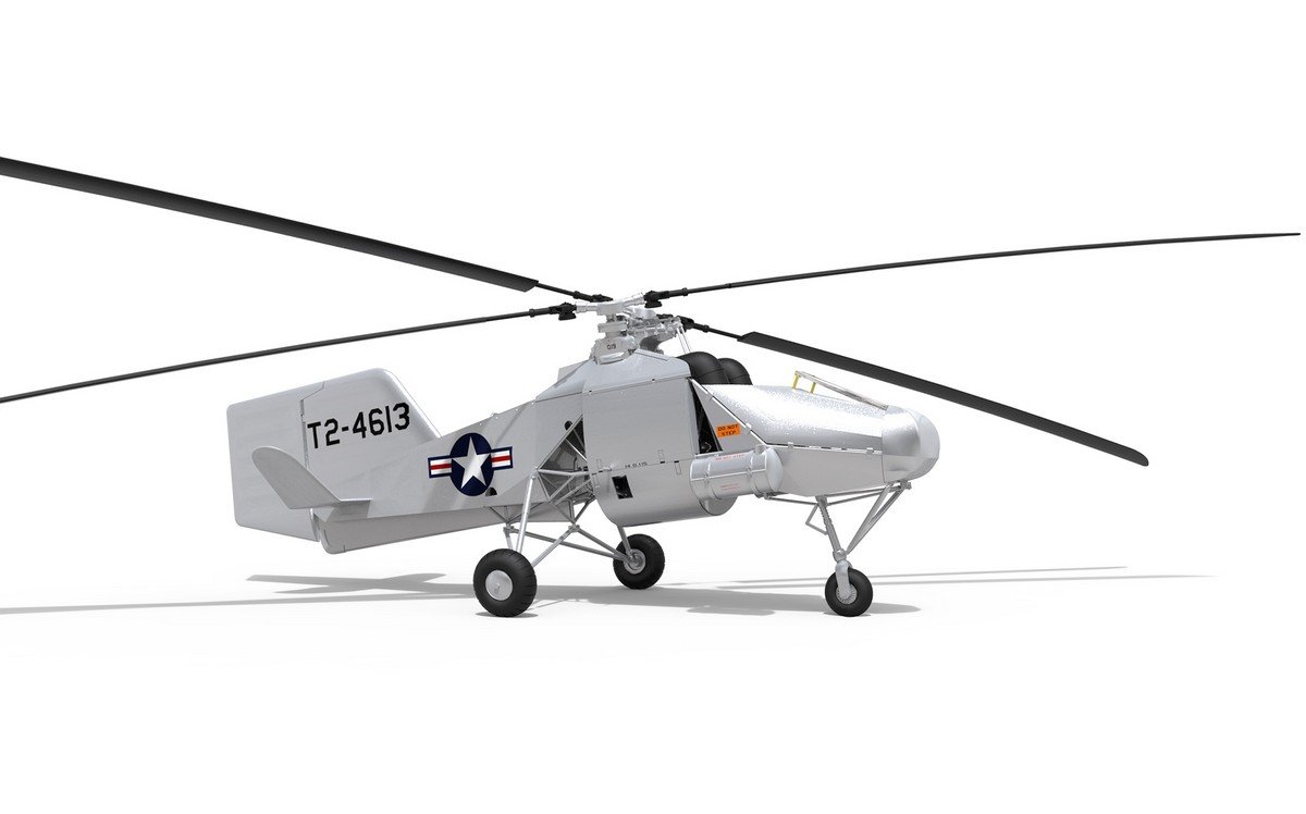
When Ukrainian company, MiniArt, announced their first Fl 282 kit, it caught us all pretty much by surprise, despite the companies more leftfield releases. We’ve not exactly been inundated with large scale models of this quirky yet important helicopter, with the only other kit being Anyuta’s 3D-printed 1/18 kit. MiniArt’s initial release started to trickle into retailers earlier this year, and this new kit only shares some of the DNA of the previous, with lots of new plastic here, including the second crew seat within the rear fuselage, behind the engine. This release is packaged into a box which is perhaps a little bigger than it should be, with the bag of contents rattling around it inside. The box artwork depicts the V-23 machine in its US colours and doped silver finish, flying high over American terrain, circa 1947. Box side images show some coloured CAD renders of the Fl 282. Inside the box, EIGHT medium-grey sprues are packed into two bags, and then sealed into a single, heat-sealed bag. Out of those grey sprues, two are duplicates (rotors), and a small clear sprue is separately packed within the main bag to protect it from scuffing. A single PE fret is included, and this is packaged into a small cardboard sleeve. Of course, decals are also a part of this release, and the small sheet is also packaged into a separate sleeve, again within the main bag. The kit’s instruction manual is a 12-page A4 publication in a mix of matt and glossy paper, with the glossy leaves containing the various artworks etc. More on that later.
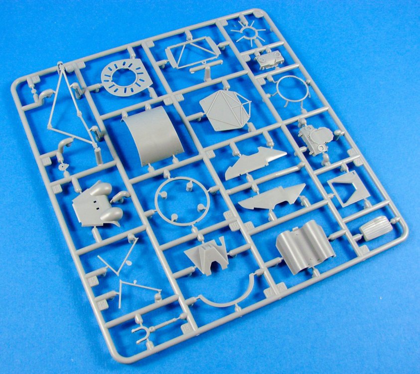
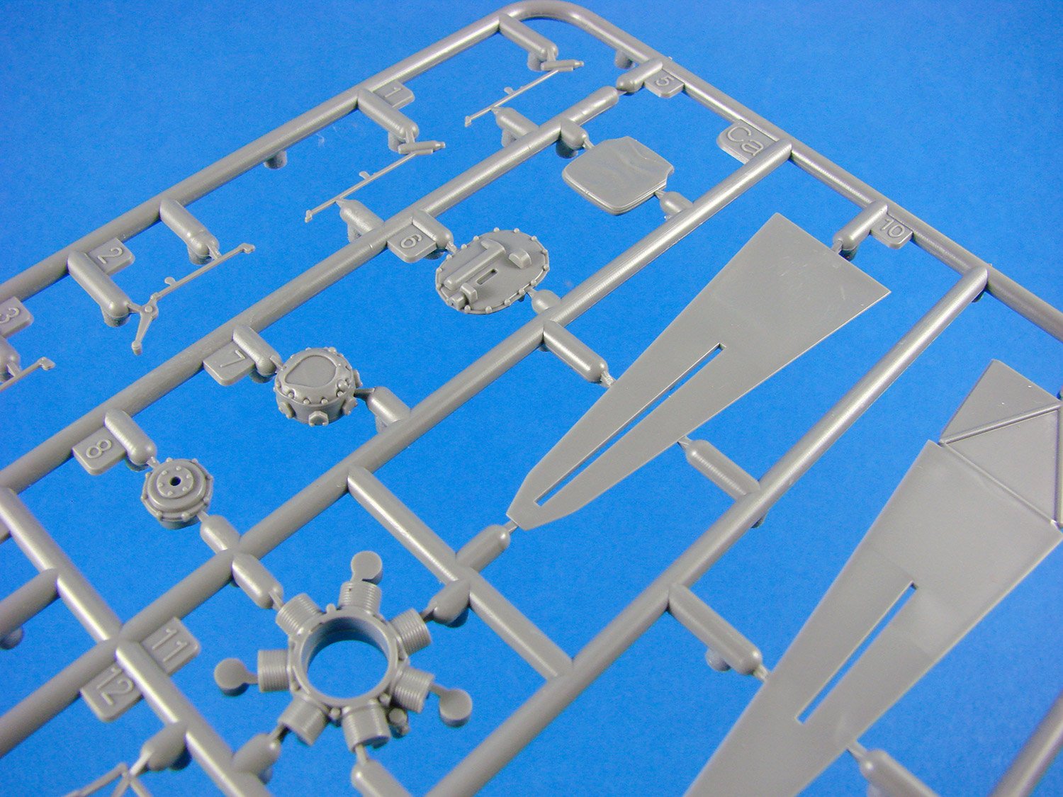
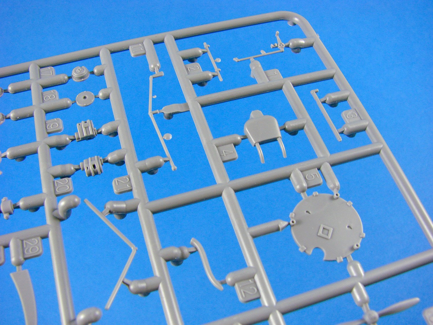
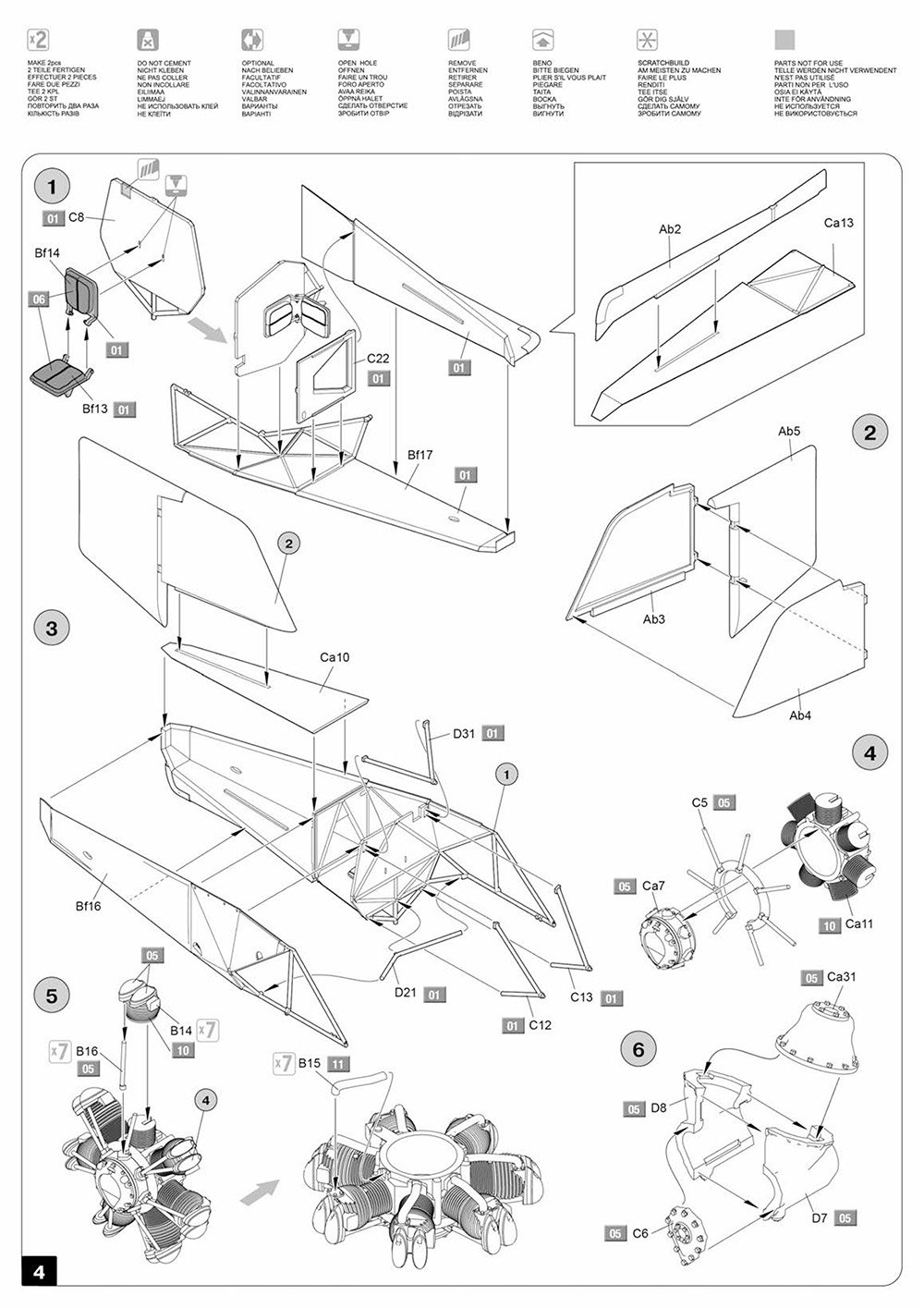
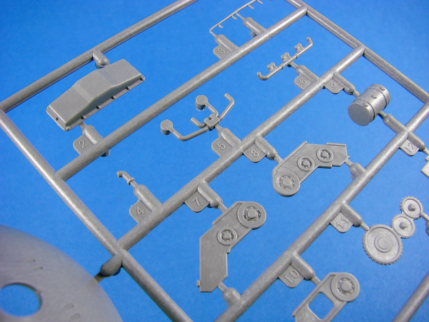
Sprue Ab
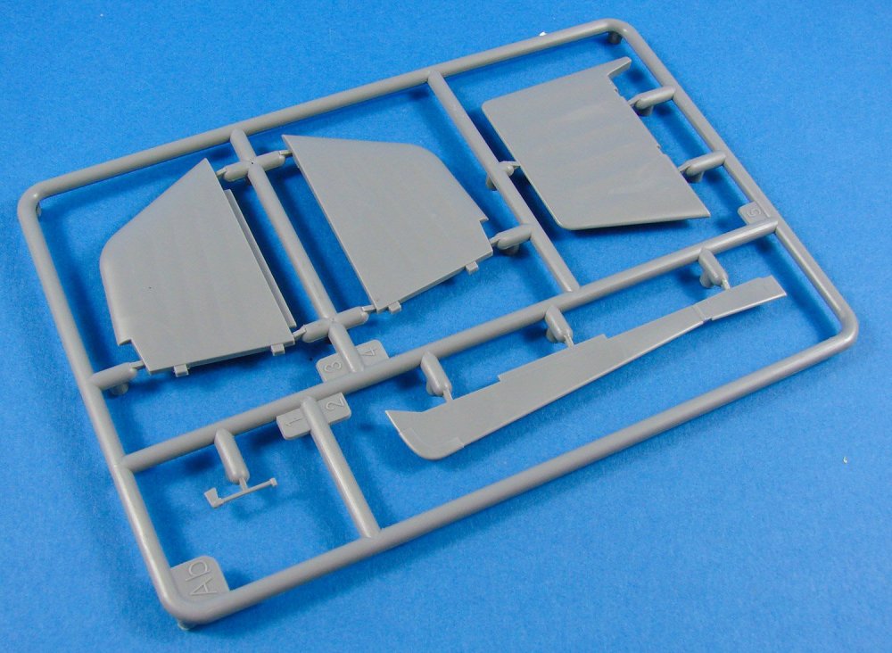
We only have five parts on this small sprue. These are for the fin, rudder, lower fuselage fairing, and rudder actuator. The fin is produced in halves, whilst the rudder is a single piece. All of these parts exhibit a very nice rib and fabric finish which I am certainly more than happy with.
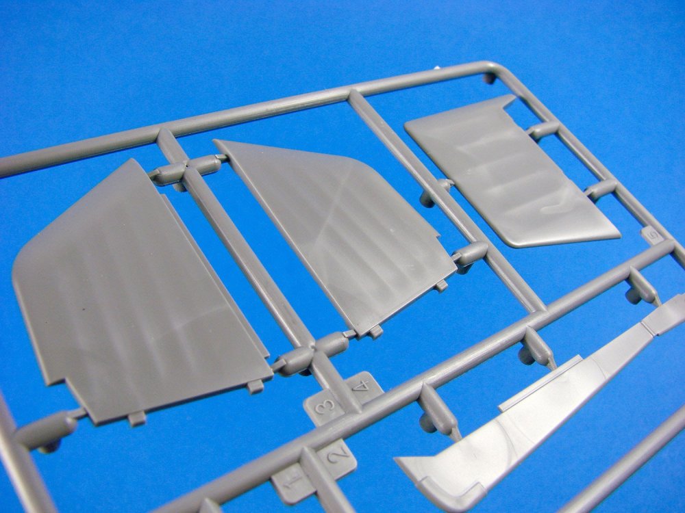
Sprue Ac
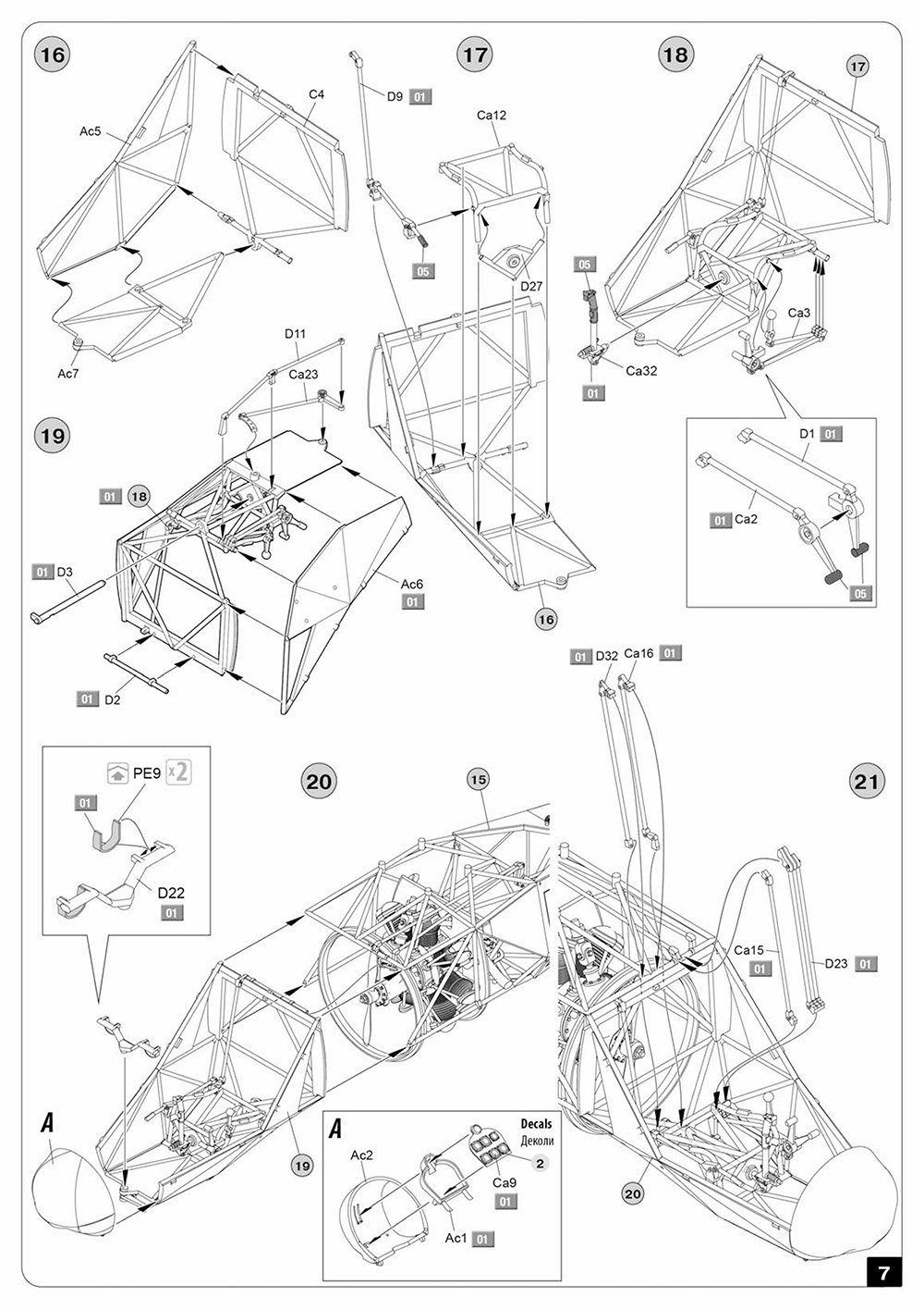
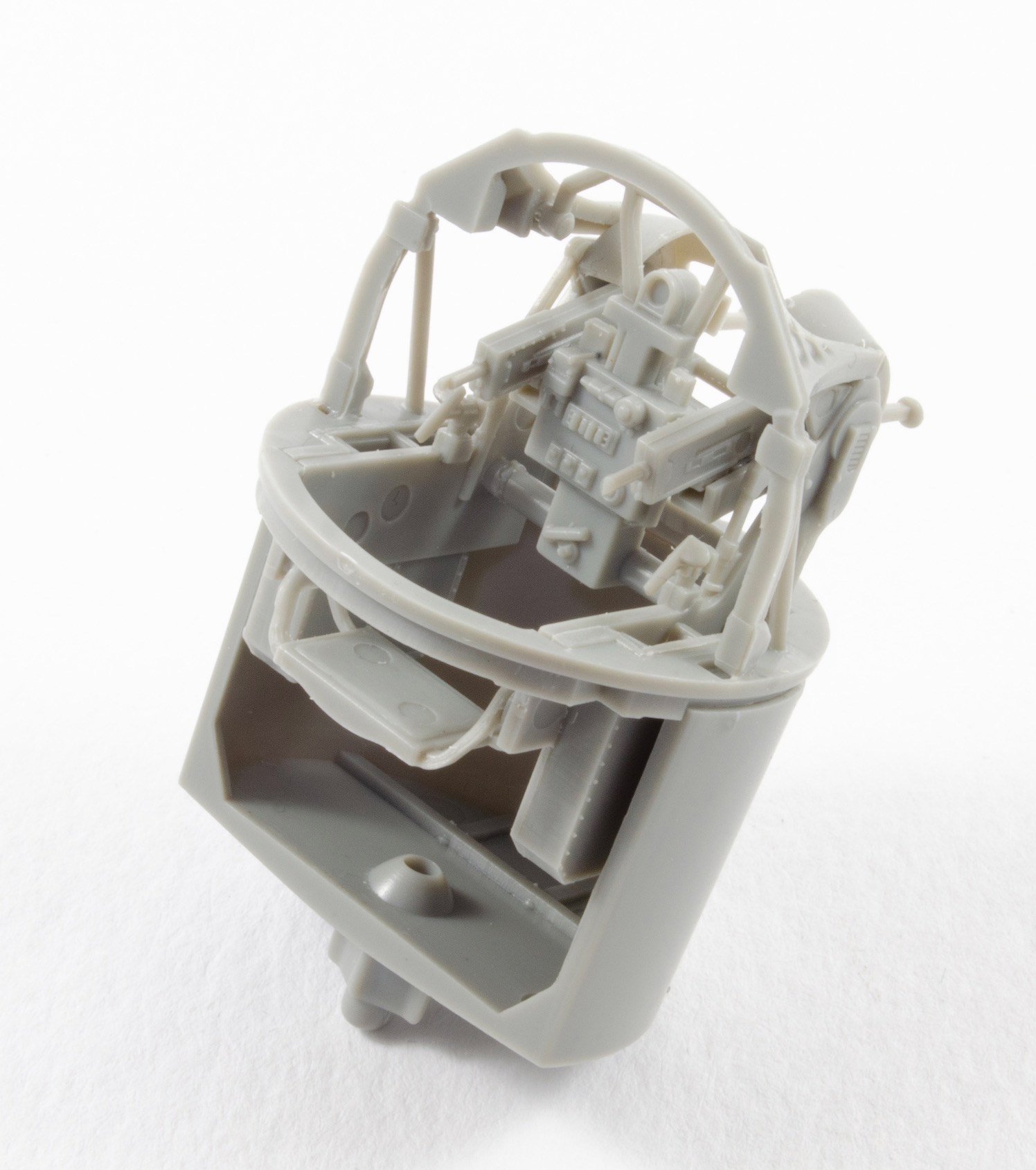
Here we see the major changes between the original V-6 kit release and this new incarnation. However, not all changes are manifested here. The V-23 had different horizontal tail planes which were kinked upwards not far from their root, and these are moulded here as single-piece units. Quite a lot of cockpit enhancements are found here too, such as the fabric and ribbed nose, lower floor tubular frame and covered side frame panels, instrument panel frame, upper cockpit tub cowl, and brackets to mount the external fuel tanks which sit either side of the cockpit tub.

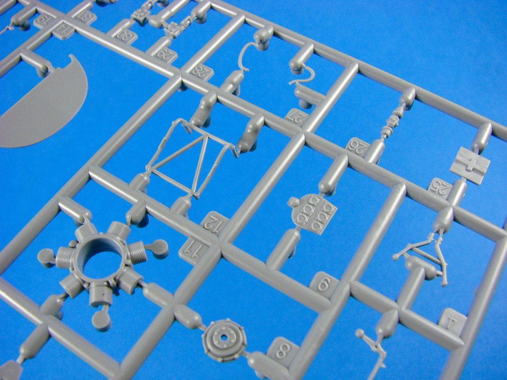
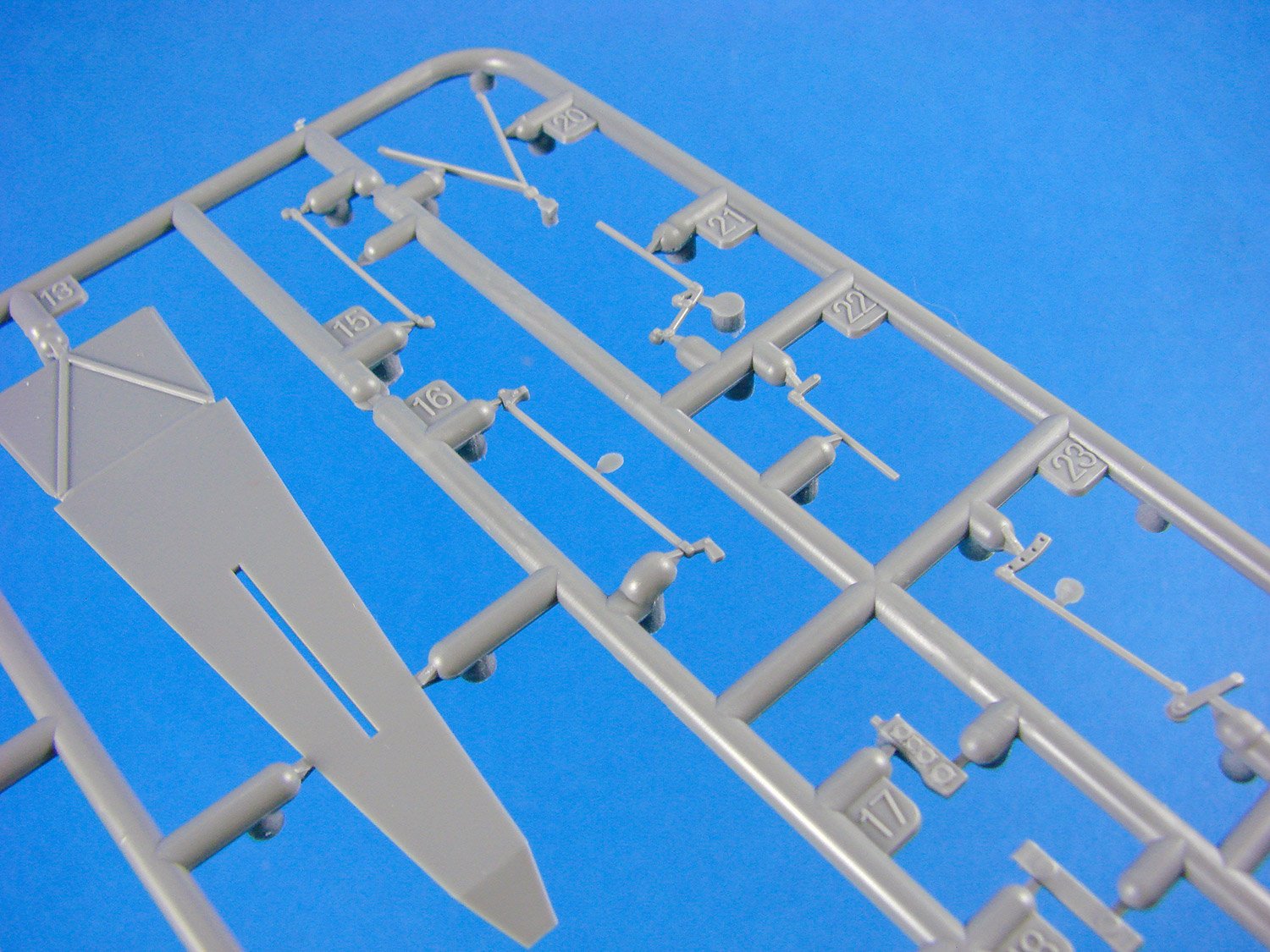
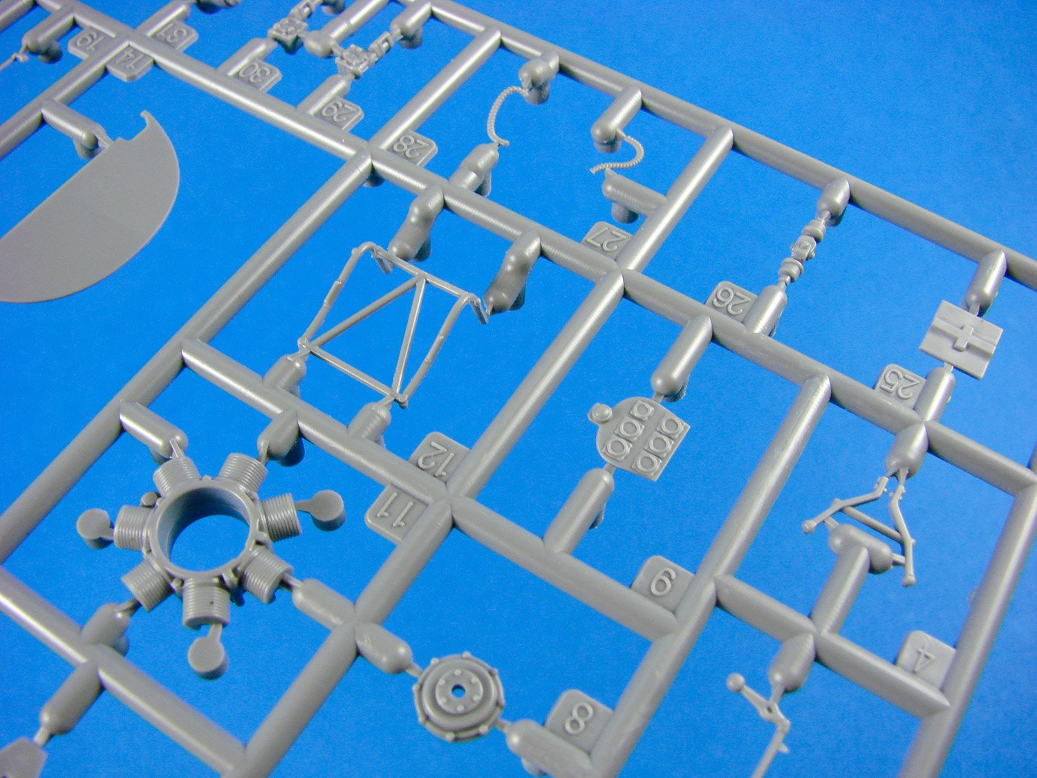
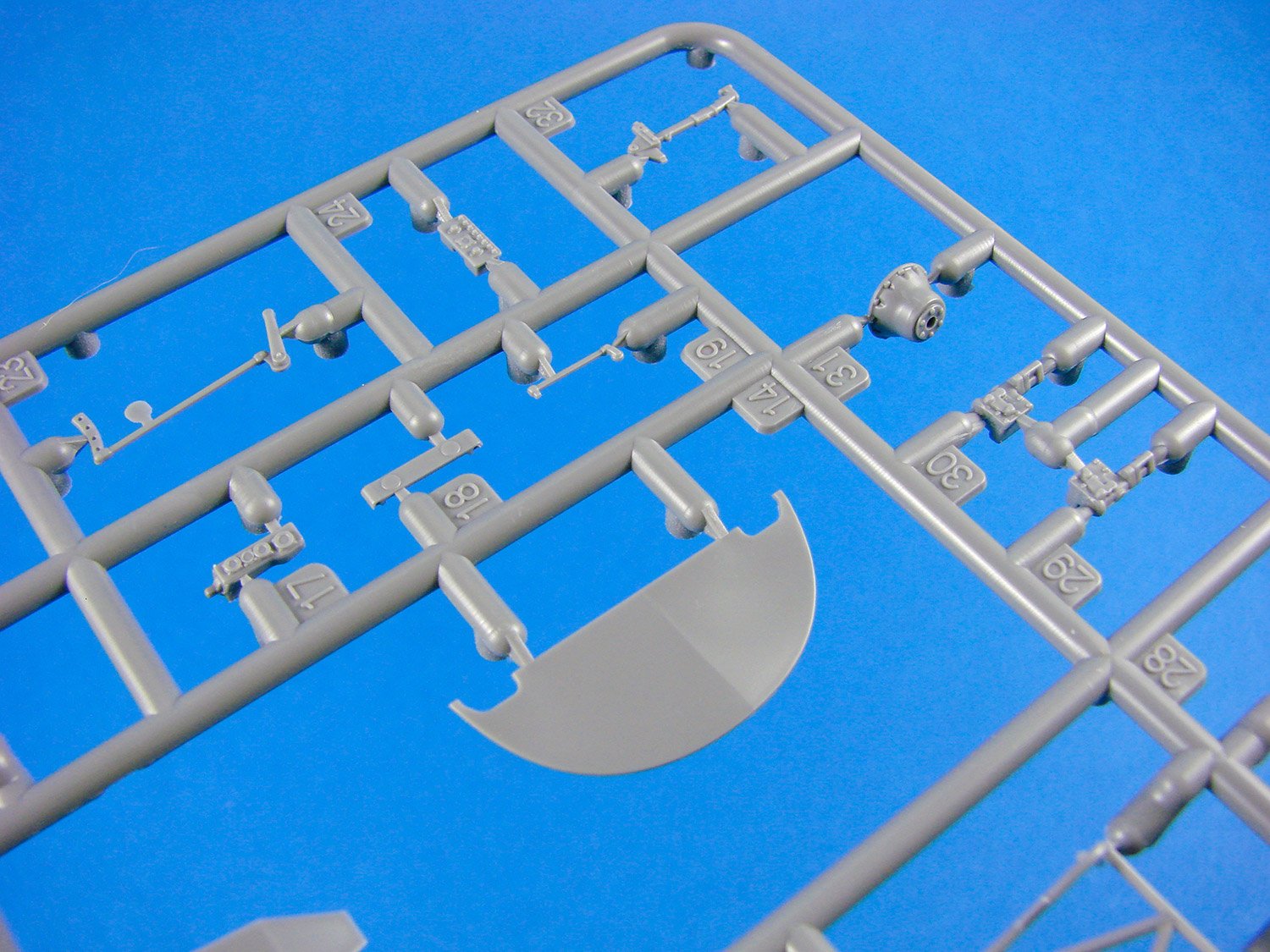
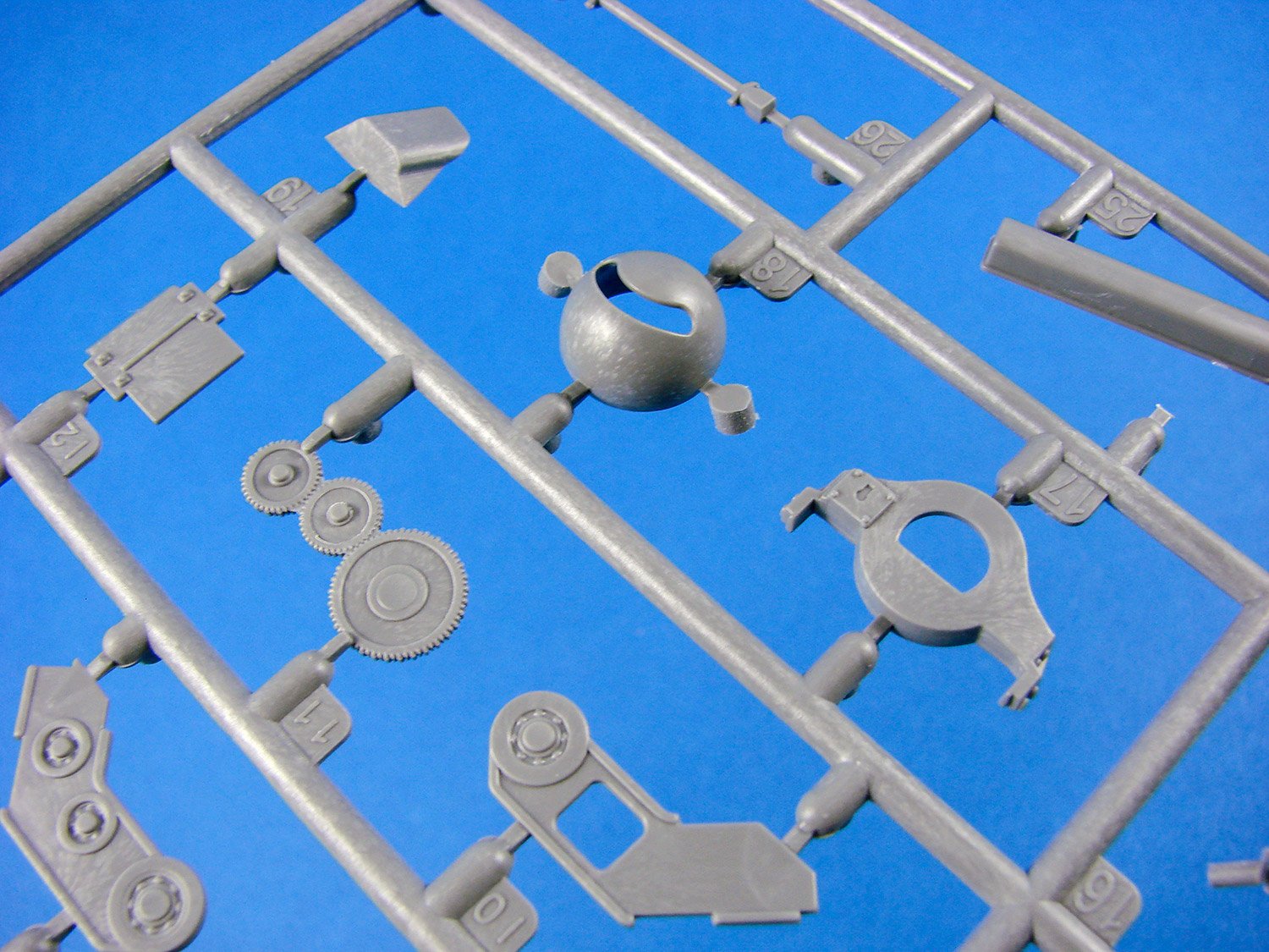
Sprue B (x2)

Remember, this isn’t a 4-blade rotor, but instead two 2-blade intermeshing rotors. Here you can see the blades for those, moulded with a sag in them so that you don’t need to manipulate the plastic and bend them yourselves. Other parts on here are for the two-part main and nose gear wheels, engine and gearbox parts, and rotor connection areas etc. Whilst the wheels don’t have any flat spots on them for the weighted effect, they are still bulged, strangely enough, in that area.
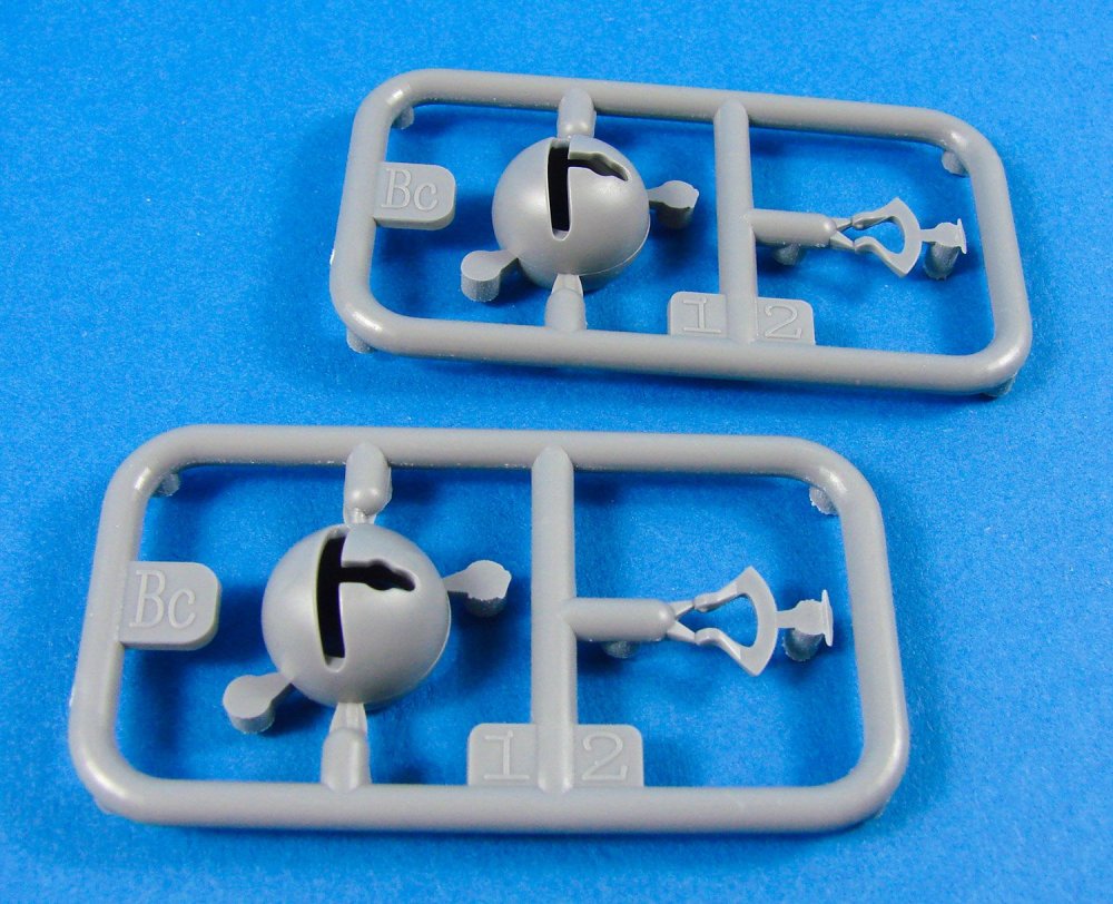
Sprue Bc
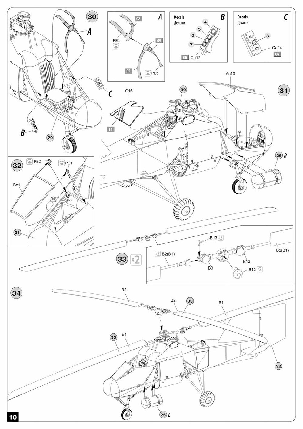
Here, we have the only clear part on the whole model, and this is the rather slick looking, sloped windscreen. Moulding is superb and crystal clear with no distortion present.
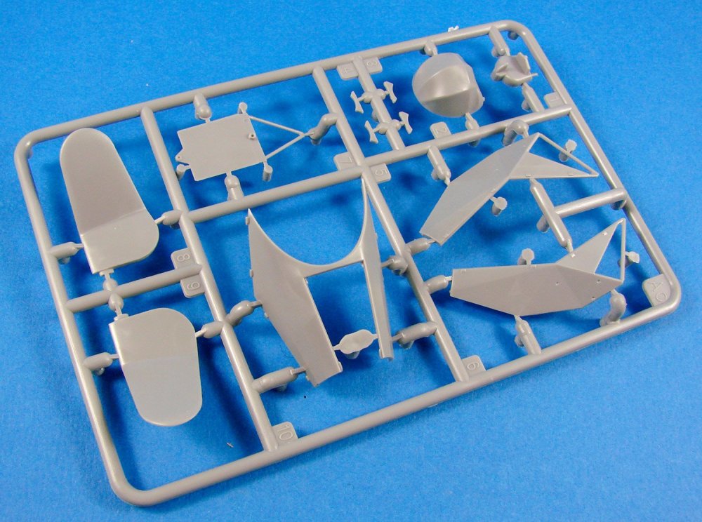
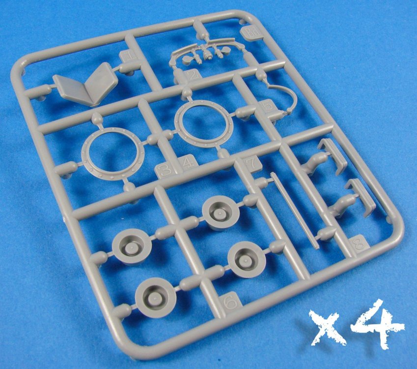
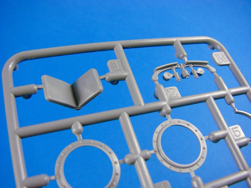
Sprue Bf
On this new sprue, we are presented with most of the larger parts of the Fl 282, pertaining of course to the fuselage. The Fl 282’s fuselage was constructed from tubular steel and the majority of it was covered in fabric. This effect is clearly seen in the port and starboard halves, with the forward section being uncovered and the rear portion exhibiting a nicely reproduced taught fabric effect, hinting at the structures below. Note also a panel for allowing the second crew member. It would’ve been nice to have had this as a separate part. Other parts on this sprue are the upper deck with forward tubular framework, engine side panels and control surface rods. In order to cater to the multitude of thin frame parts, MiniArt has used a series of small tags for their ejector pins, and these simply need to be snipped off and cleaned up

You will also find the parts for the two external fuel tanks, presumably moved to the sides of the cockpit in order to accommodate the second crew member in the rear fuselage.
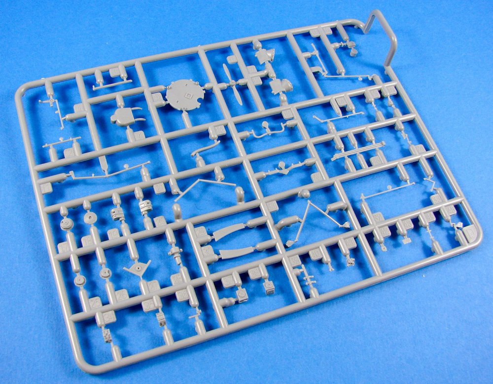
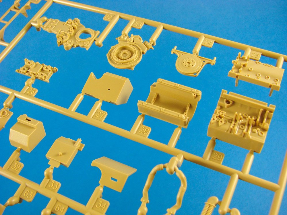
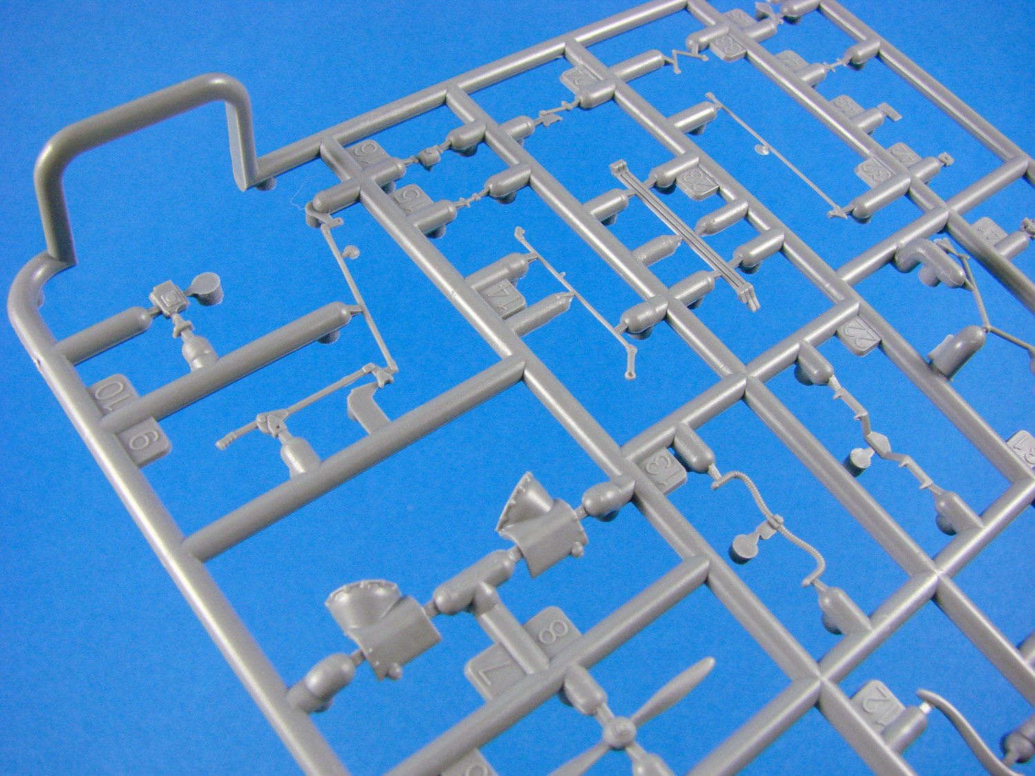
Sprue C
Here we have the lion’s share of the engineering that went into the technology that made this thing fly….i.e. engine parts and gearbox/transmission units. You’ll note engine pushrods, transmission housing plates and drive shafts, propeller housing ring, exhaust gases collector ring, pilot seat back with nicely detailed cushion, main gear spreader tubes, nose gear forked strut, etc.
A number of bulkheads are also moulded here, including the engine mounting backplate. I don’t think we can call the latter a firewall, in this instance. Note also the transmission/gearbox cowl panels and the plate which separates the brave pilot from the propeller spinning around to his rear.
Sprue Ca
I admit that the sprue nomenclature is a little confusing here. This is because MiniArt uses other sprues with different kit versions of this model. This sprue contains the engine and hub, more parts for the drive/gearing and transmission units, upper rear fuselage top into which the fin sits, lower fuselage belly, instrument panel with blank instruments (good!), pilot seat base with realistic wrinkles cockpit components, numerous other small frame components, etc.


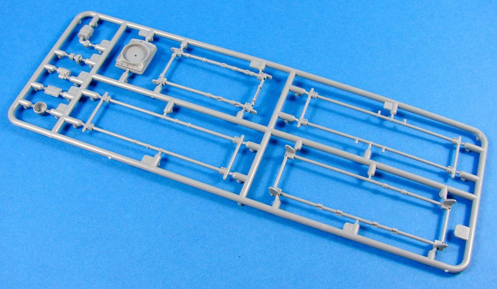
Sprue D
This is the last sprue in this release. It appears that the majority of the parts here concern the engine and other ancillary elements. Note the transmission housing, fuel piping, propeller, control rods and their linkages, side panel interior details, and of course, a few more pieces of tubular frame. This is probably the busiest of all sprues, and the parts tend to be either small or fragile, or both. One part is broken from the sprue, but that part is undamaged.


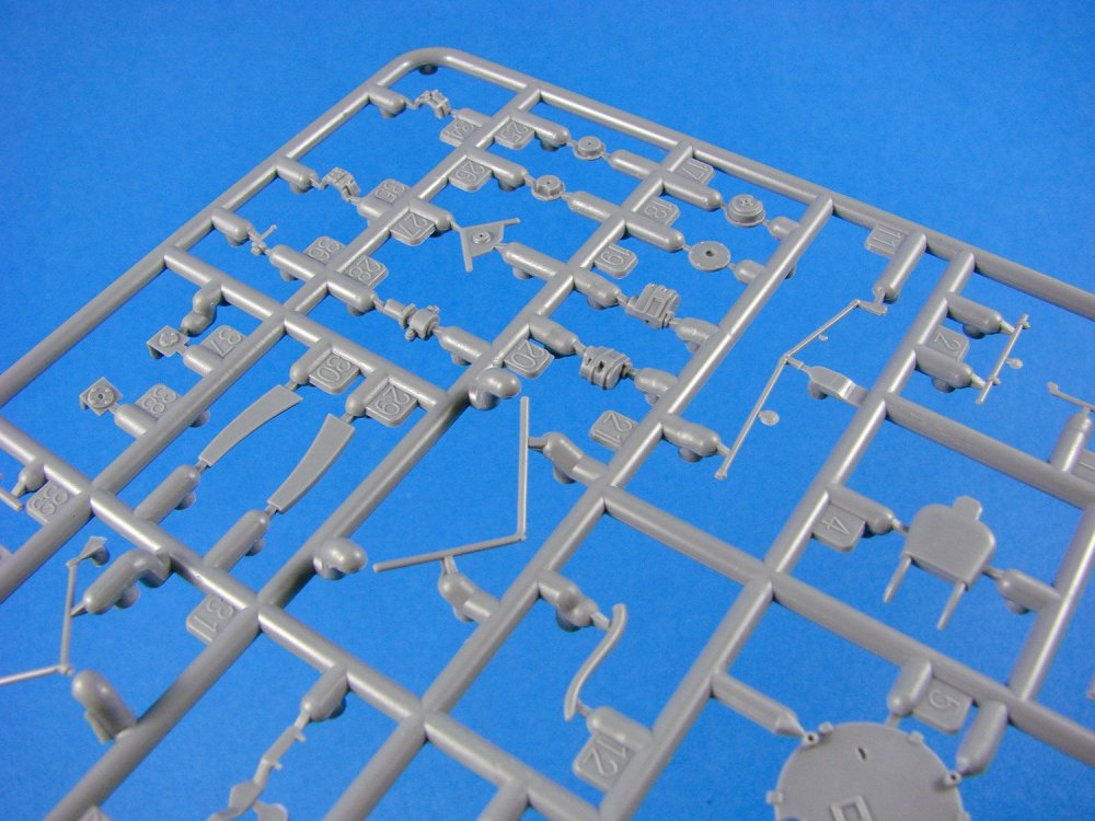

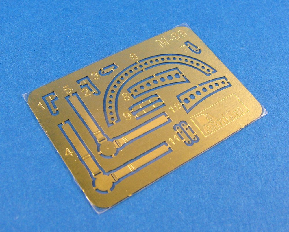
Photo Etch
Like many kits these days, this one also comes equipped with a fret of PE parts, albeit quite small. Packaged into a cardboard sleeve to protect it from the rigours of the oversized box, this fret contains 11 parts. These make up the seatbelts, frame edge sections, and a small number of parts for the engine. The PE itself is nicely manufactured and left in its bare metal state. Both sides are covered in film which needs to be removed before use.
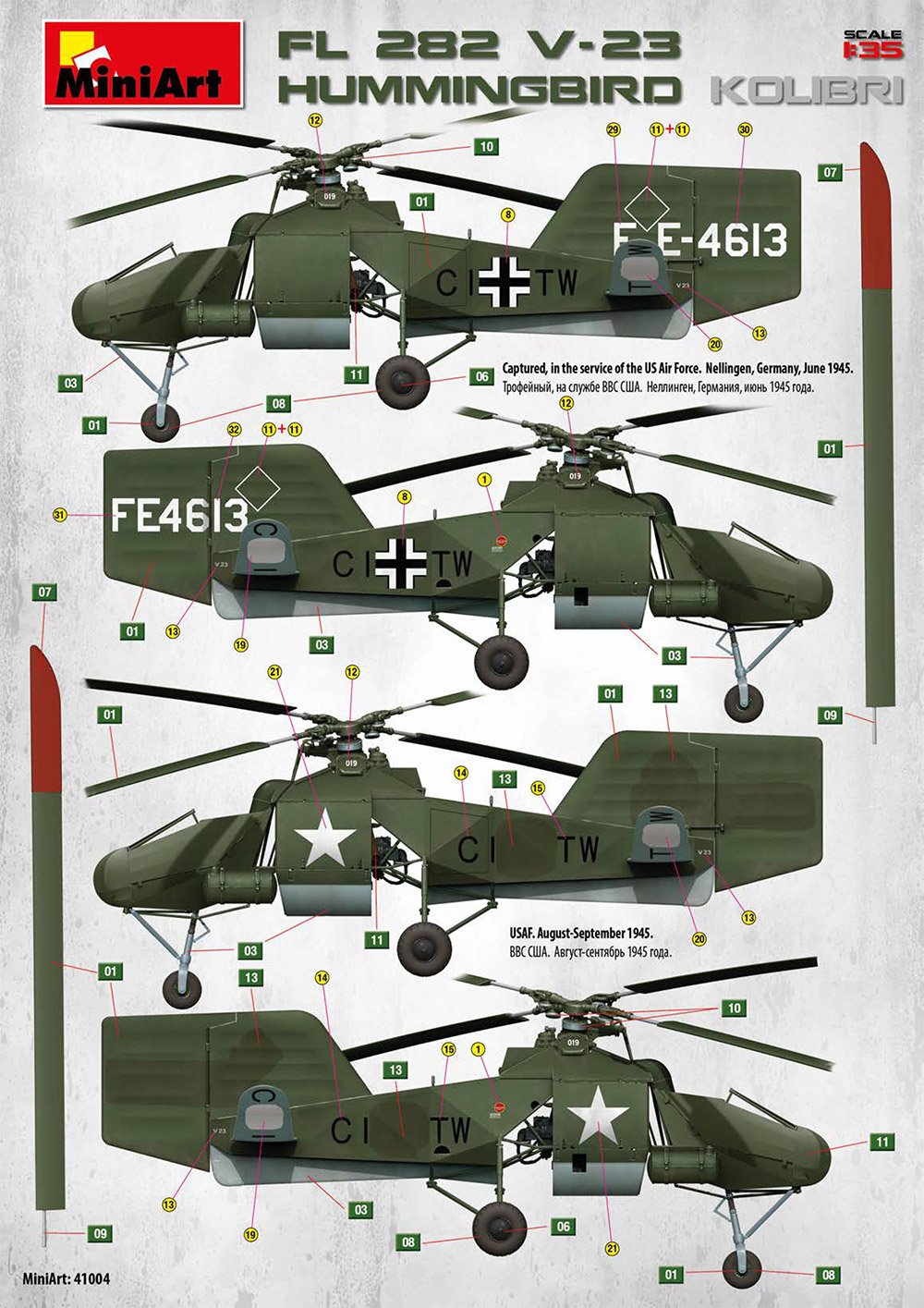
Decals
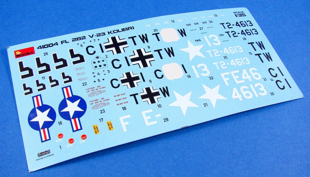
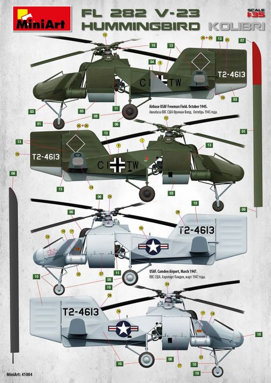
A single, small sheet of decals, printed in the Ukraine by Decograph, is included in this release. Printing is thin, with minimal carrier film and the colours appear to be opaque. Swastikas are supplied, but in a two-part format. Instrument decals are provided as a single panel or separate dials. I would use the latter, and also a punch & die to remove them so as to eliminate carrier film. The red bars on the US insignia look a little too vivid for me, but I could be wrong. The schemes provided in this kit are:
- Captured in the service of the US Air Force, Nellingen, Germany, June 1945
- USAF, August – September 1945
- Airbase USAF Freeman Field, October 1945
- USAF Camden Airport, March 1947
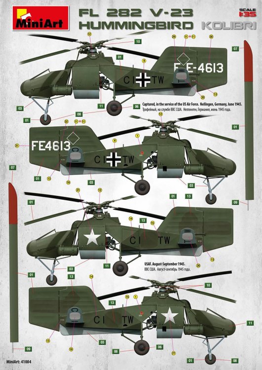
Instructions
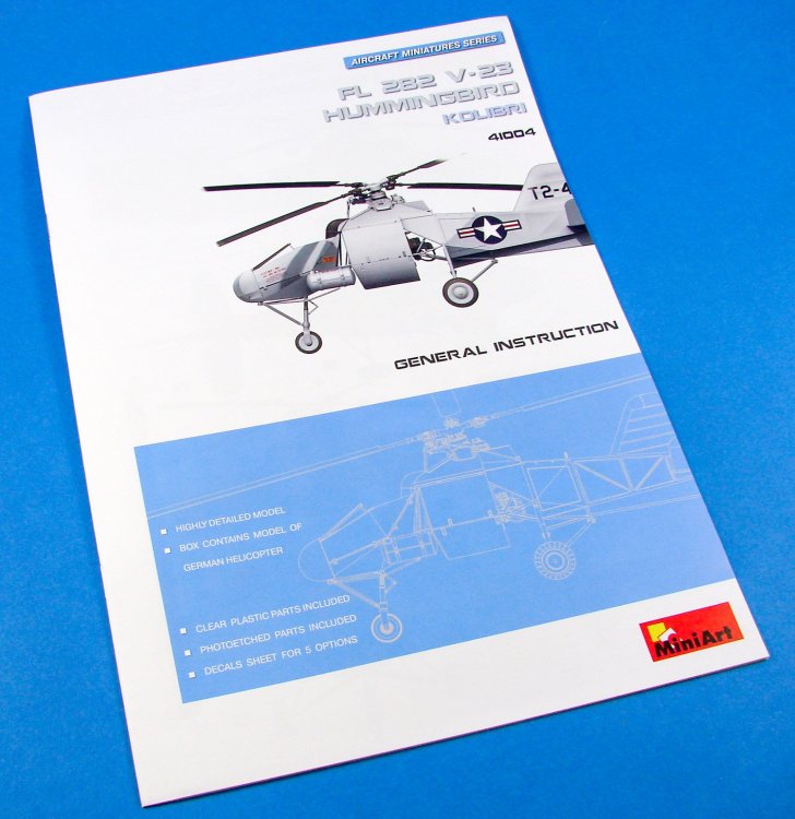
These are printed as a 12-page, glossy A4 publication, with a scheme profile and blueprint-style image on the front page, along with a brief resume of the kit contents. Inside the manual, the first thing we are presented with is a proper set of German scheme profiles for CI+TW, despite being under American ownership at that time. Please remember that all schemes in this kit are for the same prototype, and generally just vary in base colour, with the exception of the silver-doped US scheme which adorns the box lid. A parts map is then supplied, complete with a paint chart for Vallejo, Mr. Color, Humbrol, Testors, and an unknown type, with a generic list of colour names too. Construction is shown in clear line drawings over 34 stages, in easy to follow imagery and annotation. The last pages are given over to the remaining scheme profiles. Decal placement is easy to follow and the painting codes are easily referenced.


Conclusion
This is MiniArt’s second Fl 282 Kolibri release and differs in a number of ways from the original, with this only having around half of the original sprues. In that respect, it’s certainly not just an extra sprue bundled with new decals. I would say this is a release in its own right, and one that more than justifies the new catalogue number. Of course, this also includes the American scheme, which looks quite neat in doped silver, and a real contrast to the standard splinter schemes of the previous German owners. The fact that this is a two-seat machine, with a second seat in the rear fuse, also sets it aside. A great kit with a lot of detail that can be seen in and around the frames, and of course this has a proper cockpit area instead of just the tubular version we saw on the V-6 release. I really can’t fault this at all, and like MiniArt kits in general, the price-point is very attractive.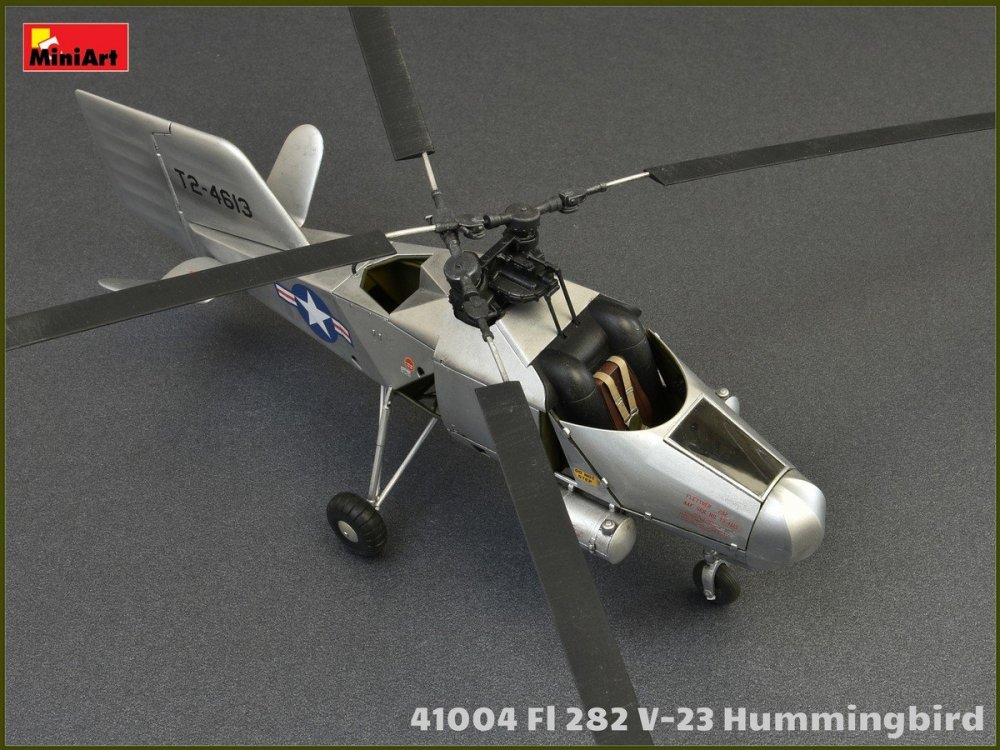

My sincere thanks to MiniArt for the sample reviewed here.

-
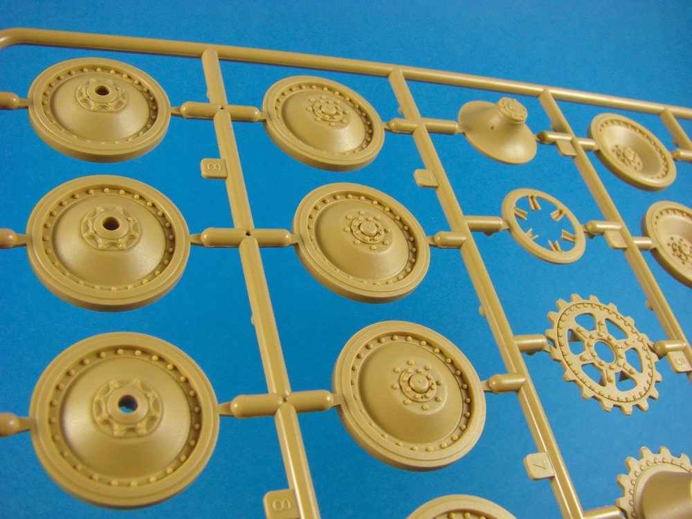
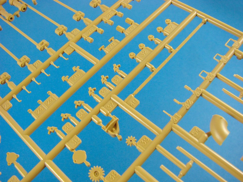
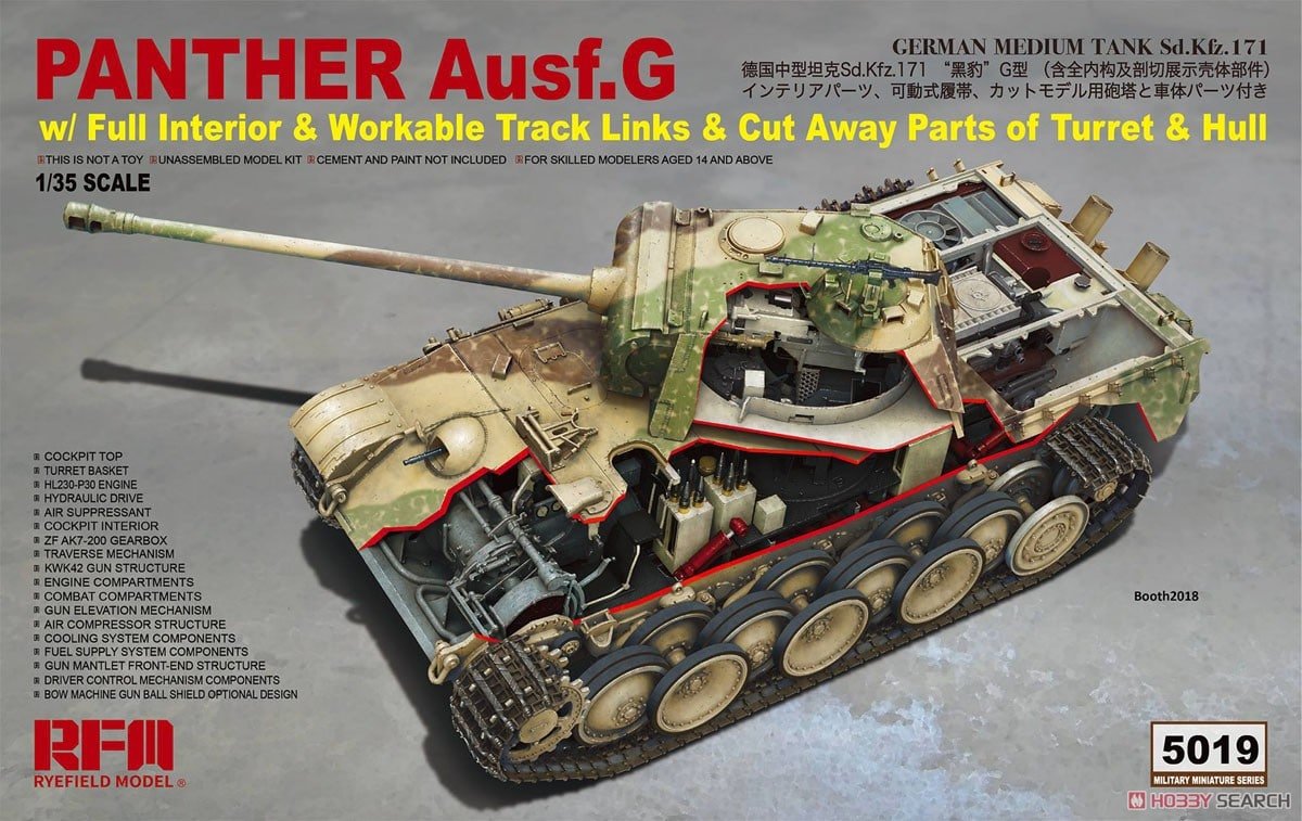
1/35 Panther Ausf.G
w/Full Interior & Workable Track Links & Cutaway Parts of Turret and Hull
Rye Field Model
Catalogue # RM-5019
The Panther is a German medium tank deployed during World War II on the Eastern and Western Fronts in Europe from mid-1943 to the war's end in 1945. It had the ordnance inventory designation of Sd.Kfz.171. It was designated as the Panzerkampfwagen V Panther until 27 February 1944, when Hitler ordered that the Roman numeral "V" be deleted. Contemporary English language reports sometimes refer to it as the Mark V. The Panther was intended to counter the Soviet T-34 and to replace the Panzer III and Panzer IV. Nevertheless, it served alongside the Panzer IV and the heavier Tiger I until the end of the war. It is considered one of the best tanks of World War II for its excellent firepower and protection, although its reliability was less impressive. The Panther was a compromise. While having essentially the same engine as the Tiger I, it had more efficient frontal hull armour, better gun penetration, was lighter and faster, and could traverse rough terrain better than the Tiger I. The trade-off was weaker side armour, which made it vulnerable to flanking fire. The Panther proved to be effective in open country and long-range engagements but did not provide enough high explosive firepower against infantry.
The Panther was far cheaper to produce than the Tiger I, and only slightly more expensive than the Panzer IV. Key elements of the Panther design, such as its armour, transmission, and final drive, were simplifications made to improve production rates and address raw material shortages. The overall design remained somewhat over-engineered. The Panther was rushed into combat at the Battle of Kursk despite numerous unresolved technical problems, leading to high losses due to mechanical failure. Most design flaws were rectified by late 1943 and the spring of 1944, though the bombing of production plants, increasing shortages of high-quality alloys for critical components, shortage of fuel and training space, and the declining quality of crews all impacted the tank's effectiveness. Though officially classified as a medium tank, its weight is more like that of a heavy tank, as its weight of 44.8 tons puts it roughly in the same category as the American M26 Pershing (41.7 tons), British Churchill (40.7 tons) and the Soviet IS-2 (46 tons) heavy tanks. The tank had a very high power to weight ratio however, making it extremely mobile regardless of its weight. Its weight still caused heavy tank-esque problems however, such as an inability to cross certain bridges.
Extract from WikipediaThe kit
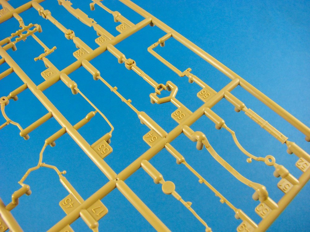
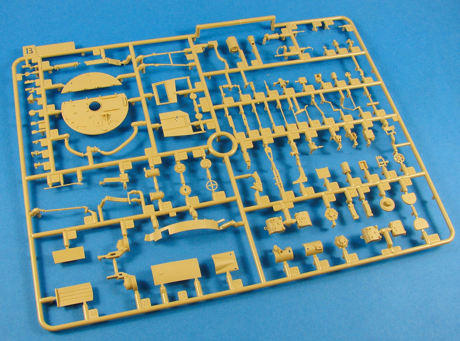
If you like large kit boxes, you’ll not be disappointed. This one contains a superb cutaway artwork of the Panther G, with the edges of the cutaway lined in red, as is typically seen in engineering models. Although this model is sold as a cutaway version, RFM has supplied the regular hull and turret parts, in case you wish to build a conventional model. This kit is certainly no weekender project.
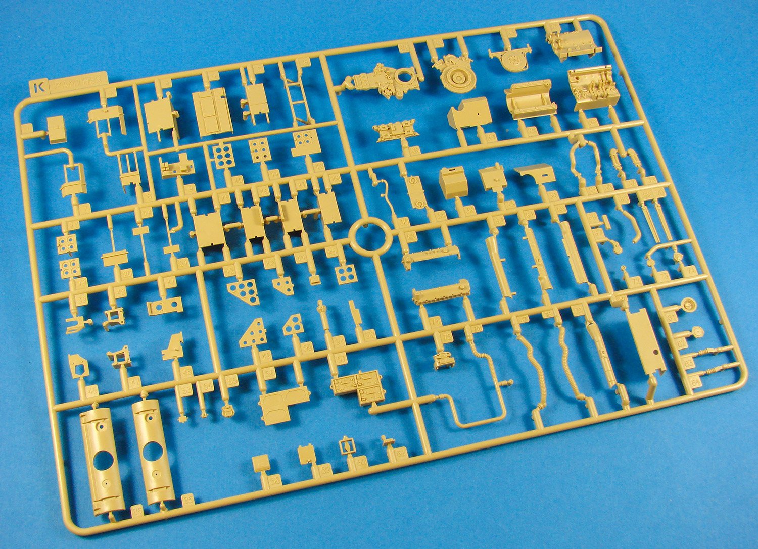
Kit sprues are moulded in a light brown styrene, and there are FOURTEEN of these. Most are individually bagged except for the ones where there are multiples. Two sprues are interconnected, with two copies, counting as four sprues. A bag containing wire and a spring also contains a flexible black sprue with captive wheel nuts and four wheel rims. Track parts (x190) are included in a brown separate bag and these, moulded in dark brown plastic, come as two per sprue. A single clear sprue is included for the periscope parts. One black, rubbery sprue is included, and TWO PE frets are supplied, one decal sheet, and lastly, a hefty 52-page instruction manual. As I said, this is no weekend project. You’ll need to set serious time aside.
We’ll now take a look through the various sprues and focus in on those fine details which really set this release apart.
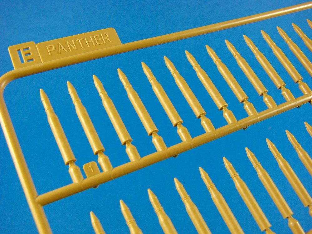
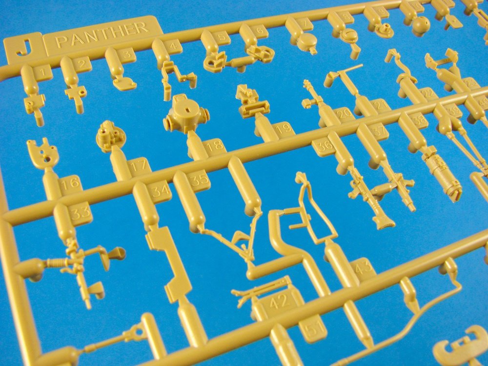
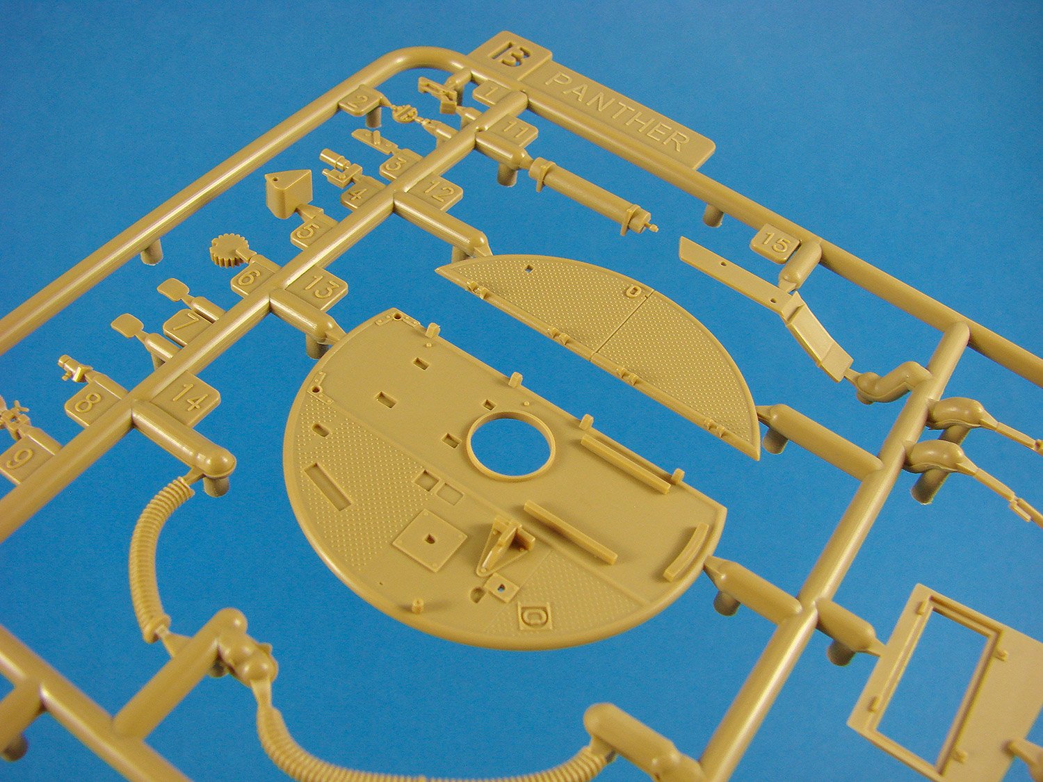
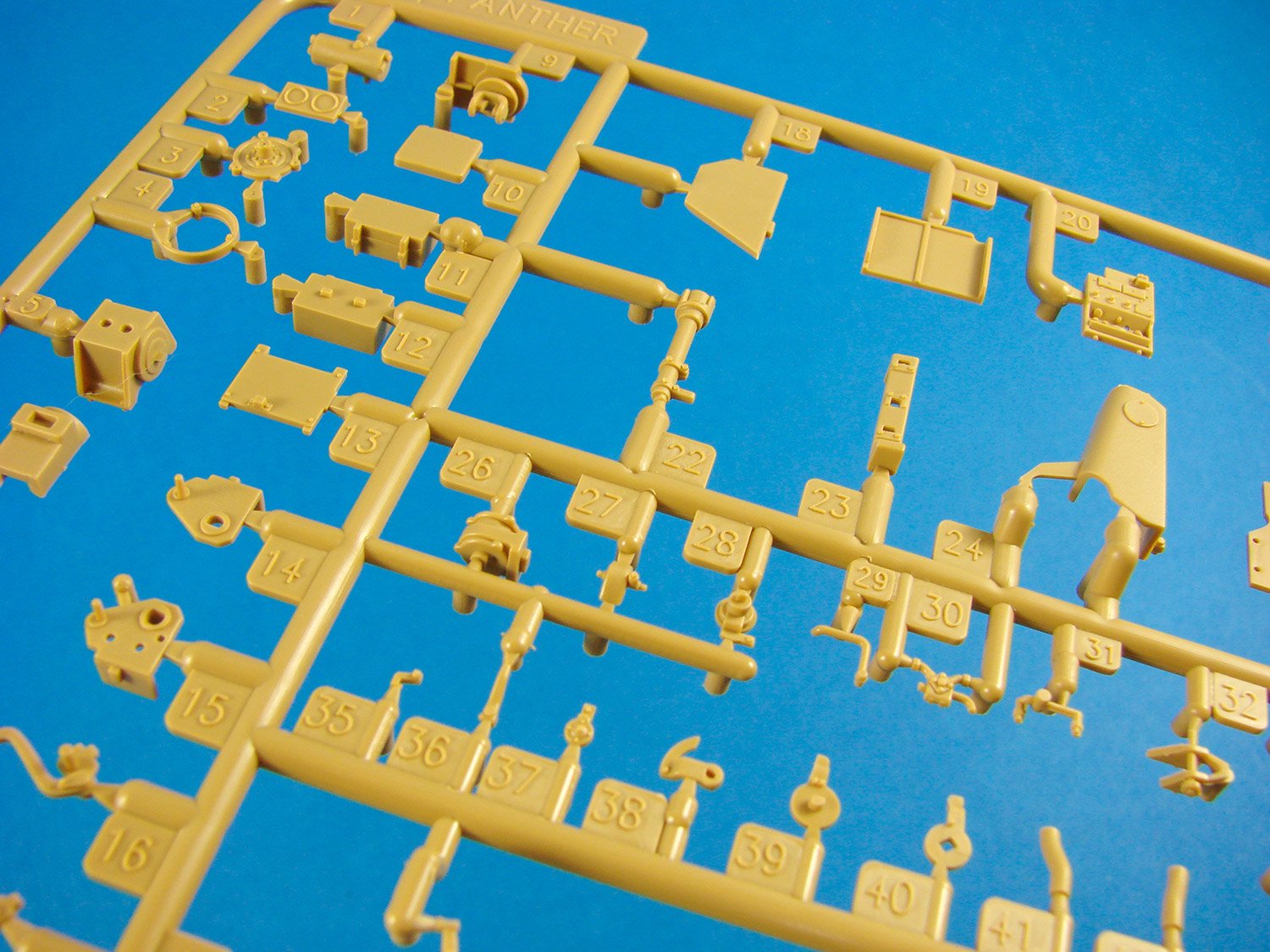
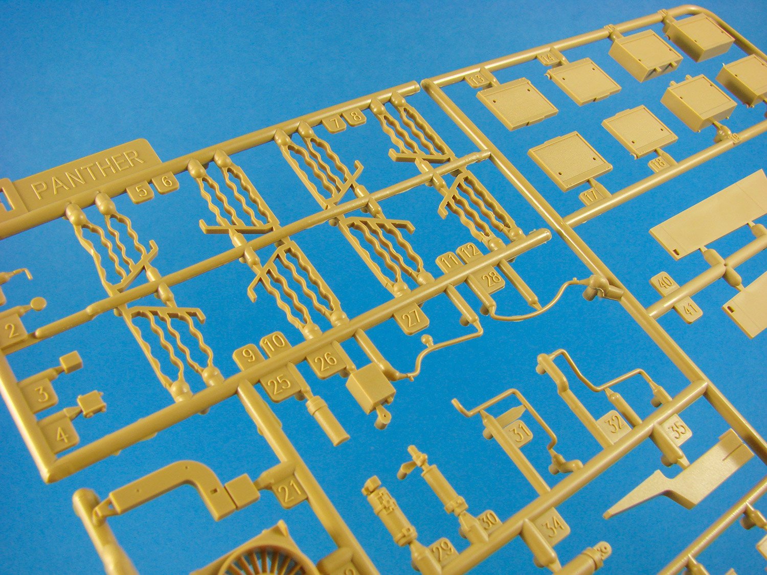
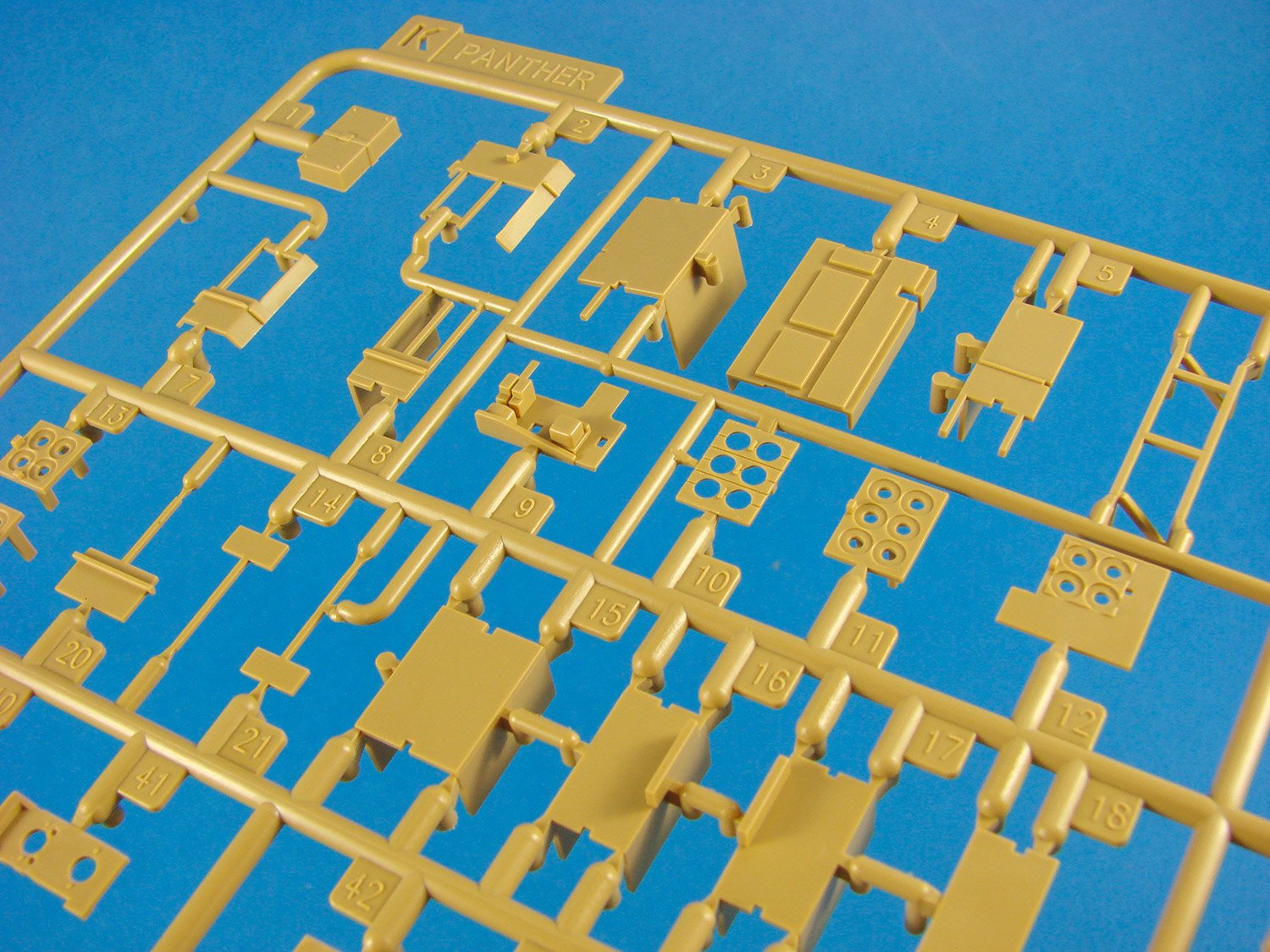
Sprue A
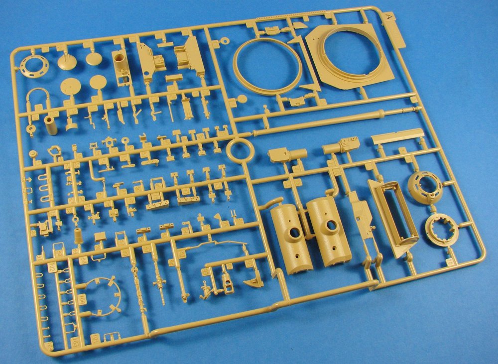
I could be wrong, but it does look like RFM has thoughtfully grouped the parts for specific areas mainly together on their respective sprues. This certainly beats the constant toing and froing between sprues, especially when there are so many as with this kit. Here we see parts that seem to exclusively concern the Panther’s powerful 7.5 cm Kwk 42 L/70 gun, including turret parts and two mantlet options. The latter are for the curved mantlet, and the later version with a vertical face below the upper curved section, providing extra armour to the lower quarters. Whilst some would decry the lack of a metal barrel in this kit, the plastic one is moulded in one piece instead of as halves. Of course, the muzzle is moulded as separate parts for which no seams exist. These details are supplemented by a little PE.


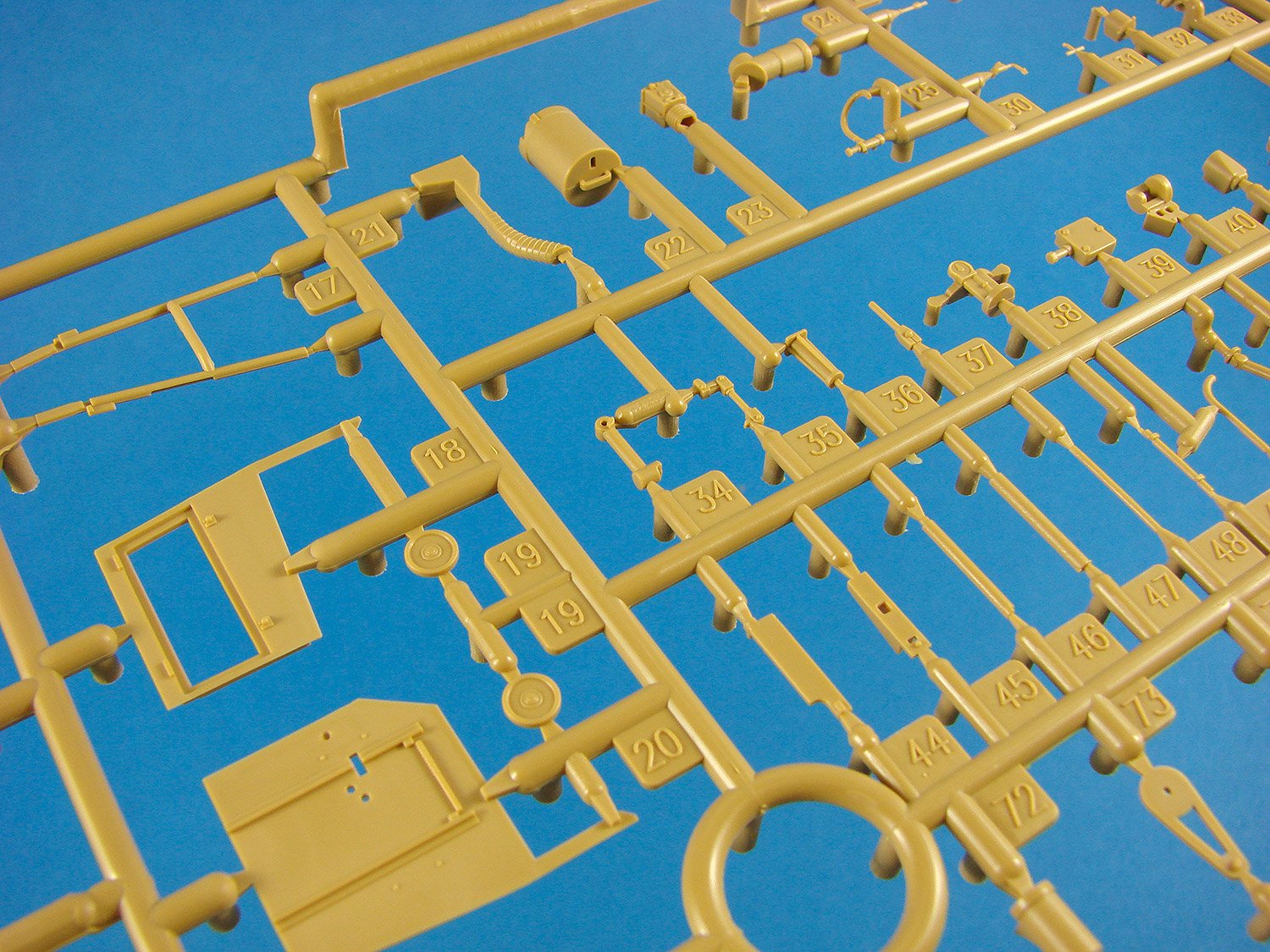
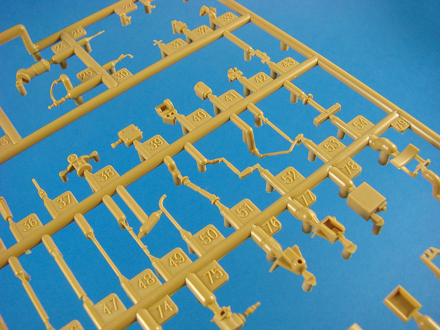
Sprue B
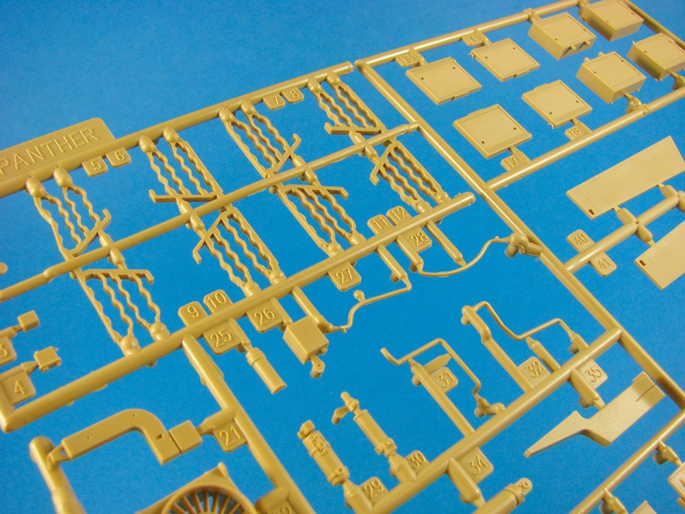
We generally have a lot of internal turret details here, ranging from the traverse motor to the gun counterbalance, hydraulic drive, loader/gunner/commander seats, azimuth etc. To say the turret interior is comprehensive is pretty much on the money. You’ll certainly need no aftermarket here. The instructions show lengths of wire that must be added using the supplied material.


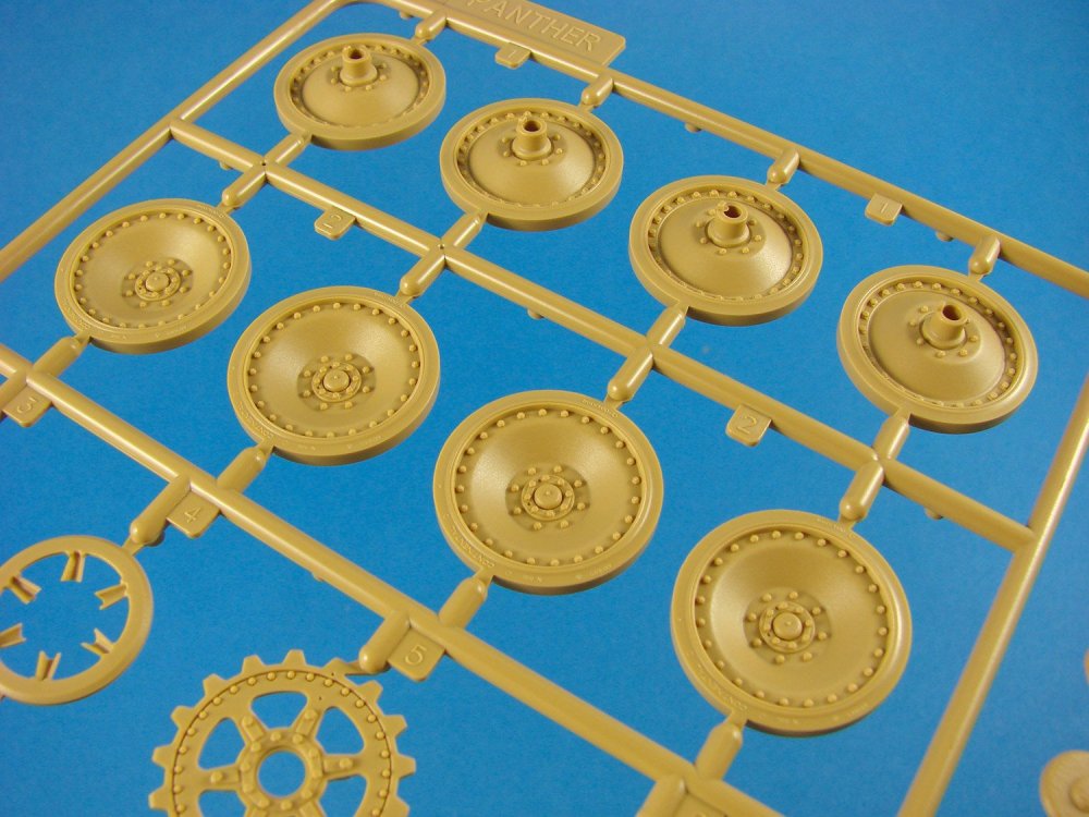
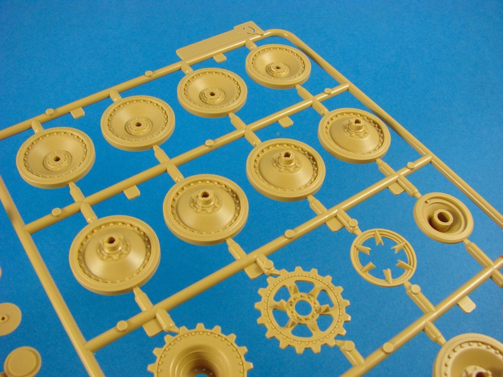
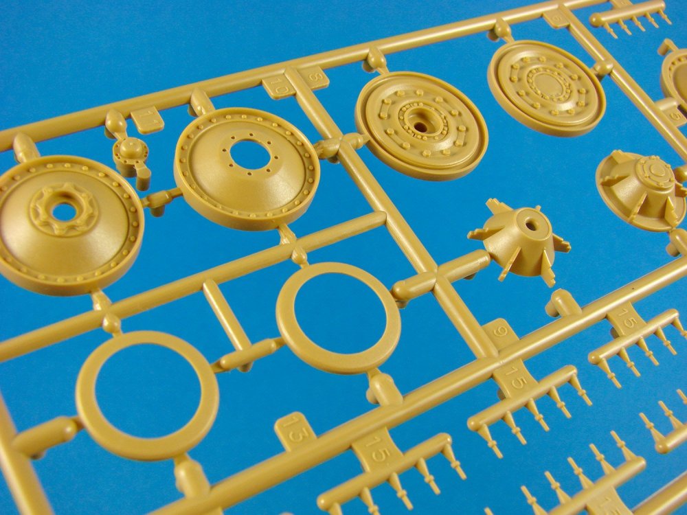
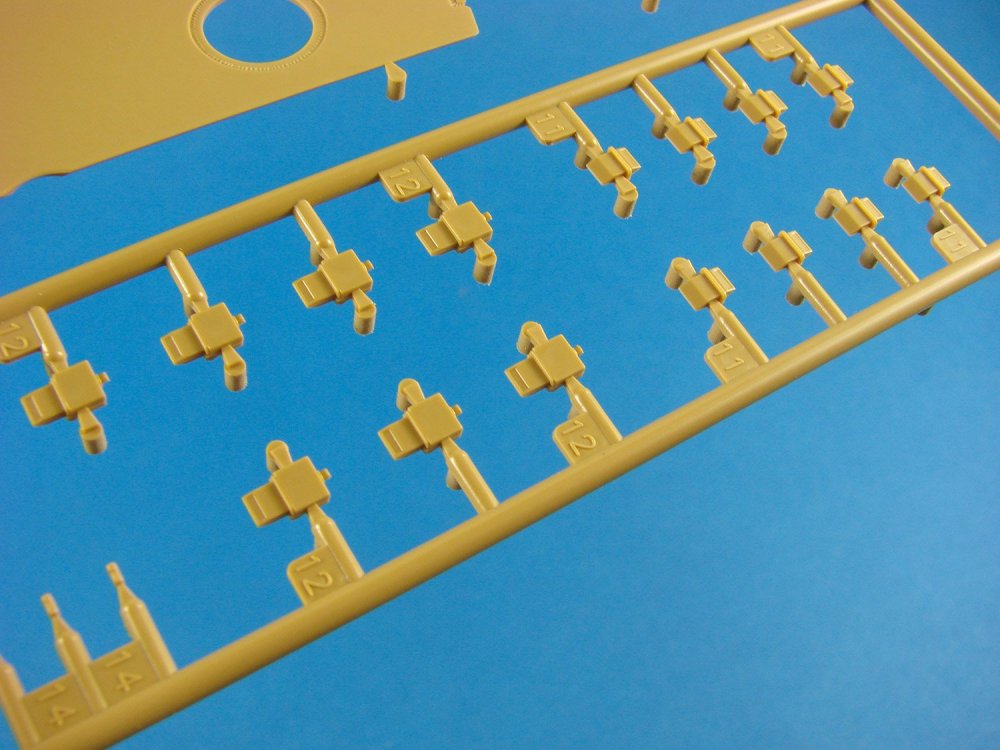
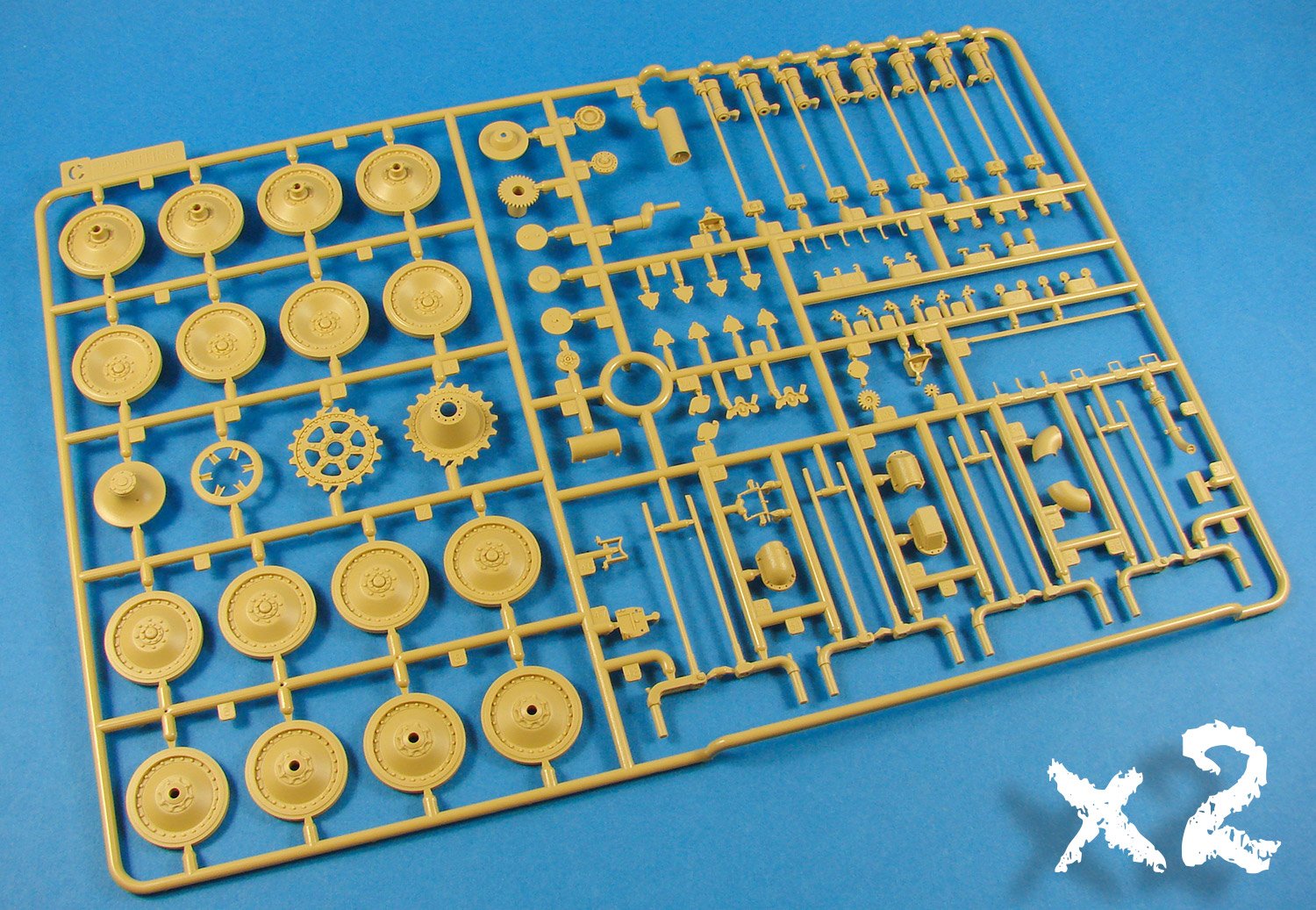
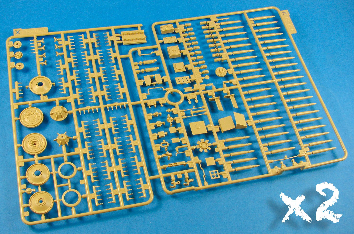
Sprue C (x2)
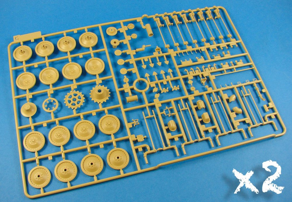
Wheels, torsion bars and other associated parts are found on this sprue, of which two are supplied. I do note a few parts from other areas of the hull, but generally this is where the rolling stuff happens. I’ve already said that the wheels/torsion bars do work, but not as they are initially moulded. If you don’t want to simply build this with static, non-moving torsion, then that is the default position. If you want them to articulate, then a small tab of plastic needs to be removed from each bar. Quite a simple task and one that satisfies all builders of this kit.
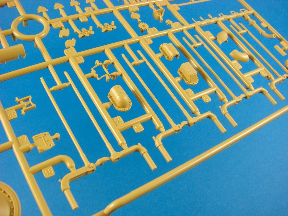
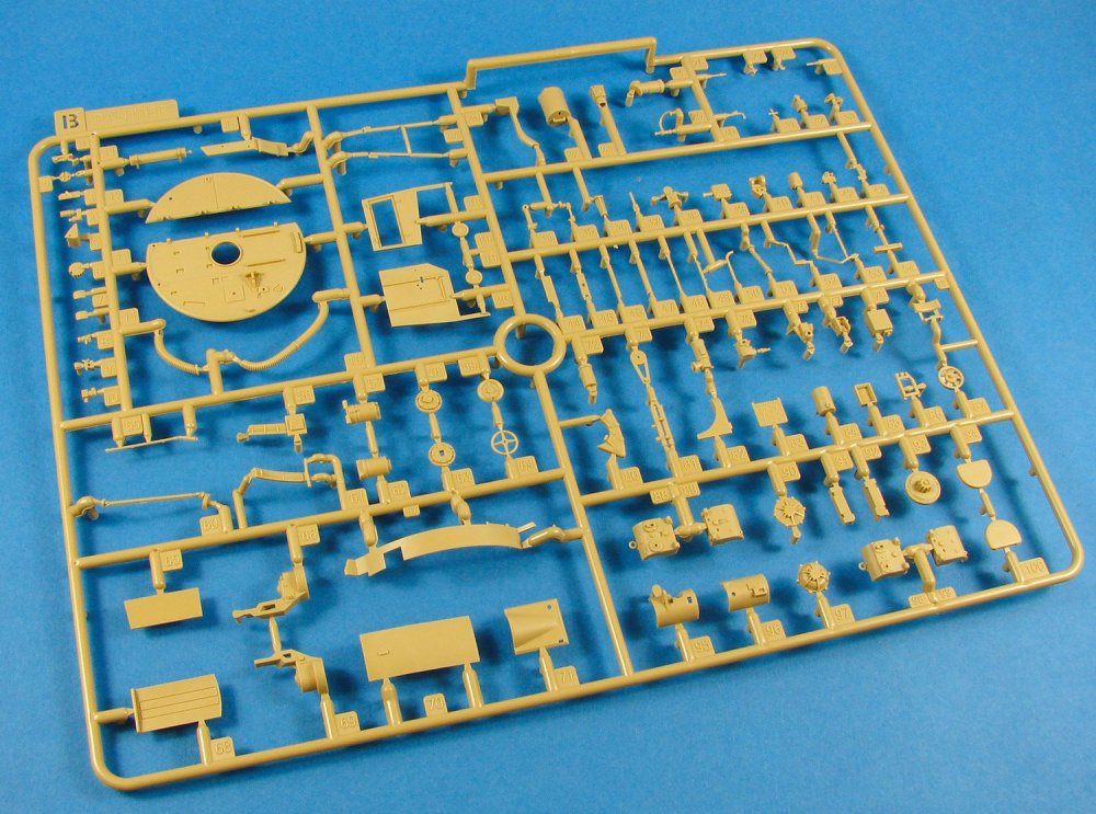
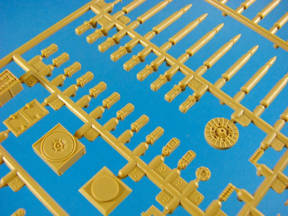
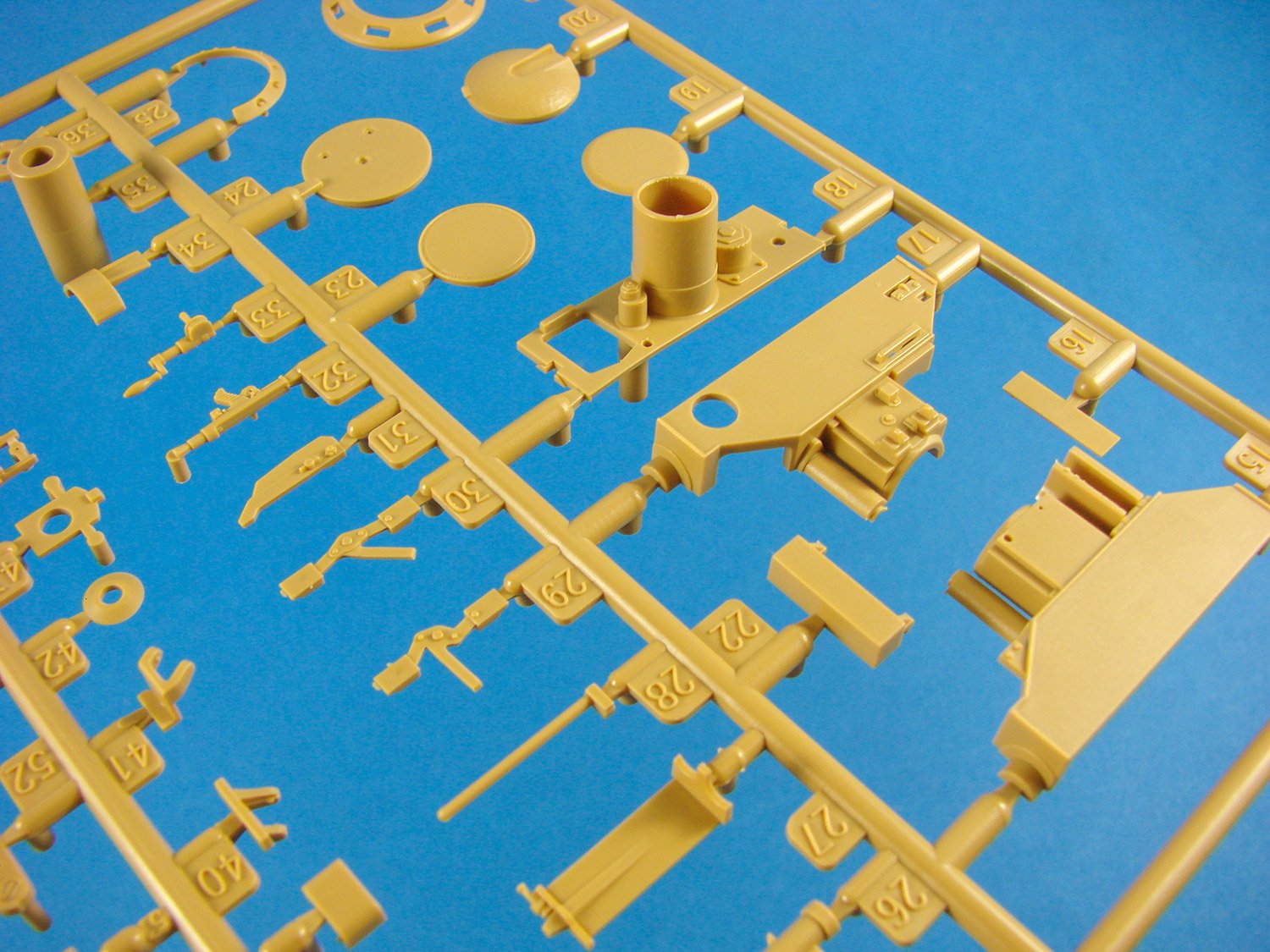
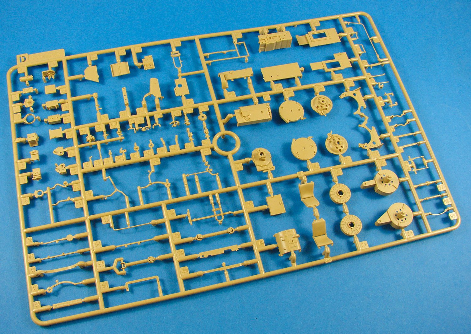
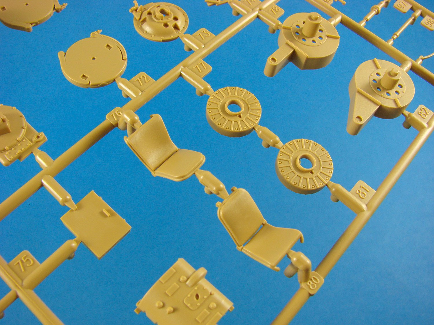
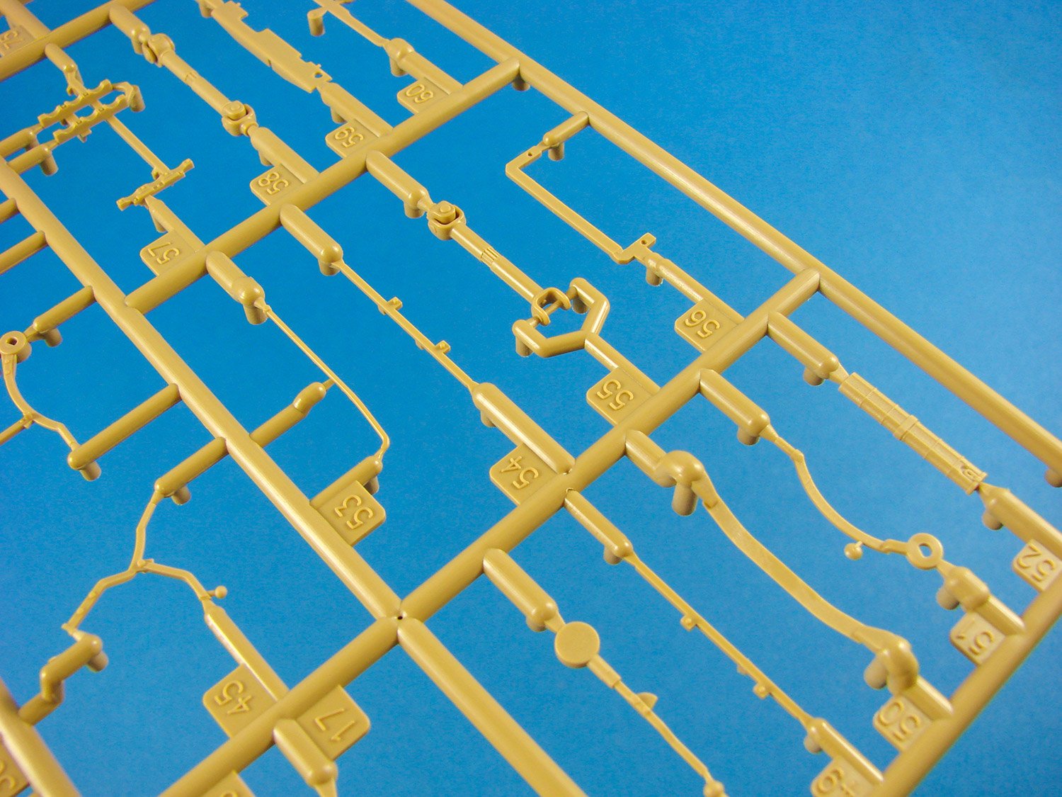
Sprue D
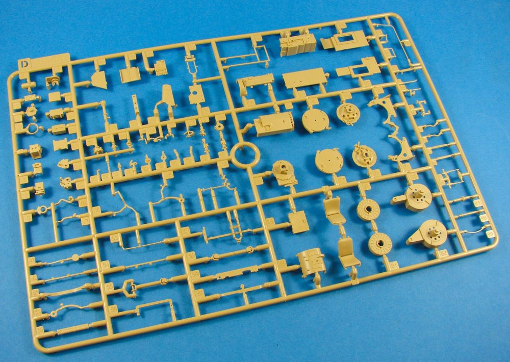
Many general interior parts here, such as the driver’s seat, transmission, comms system power supply, periscope storage, front drive brake units etc. In fact, many items from the lower hull forward interior will be found here.

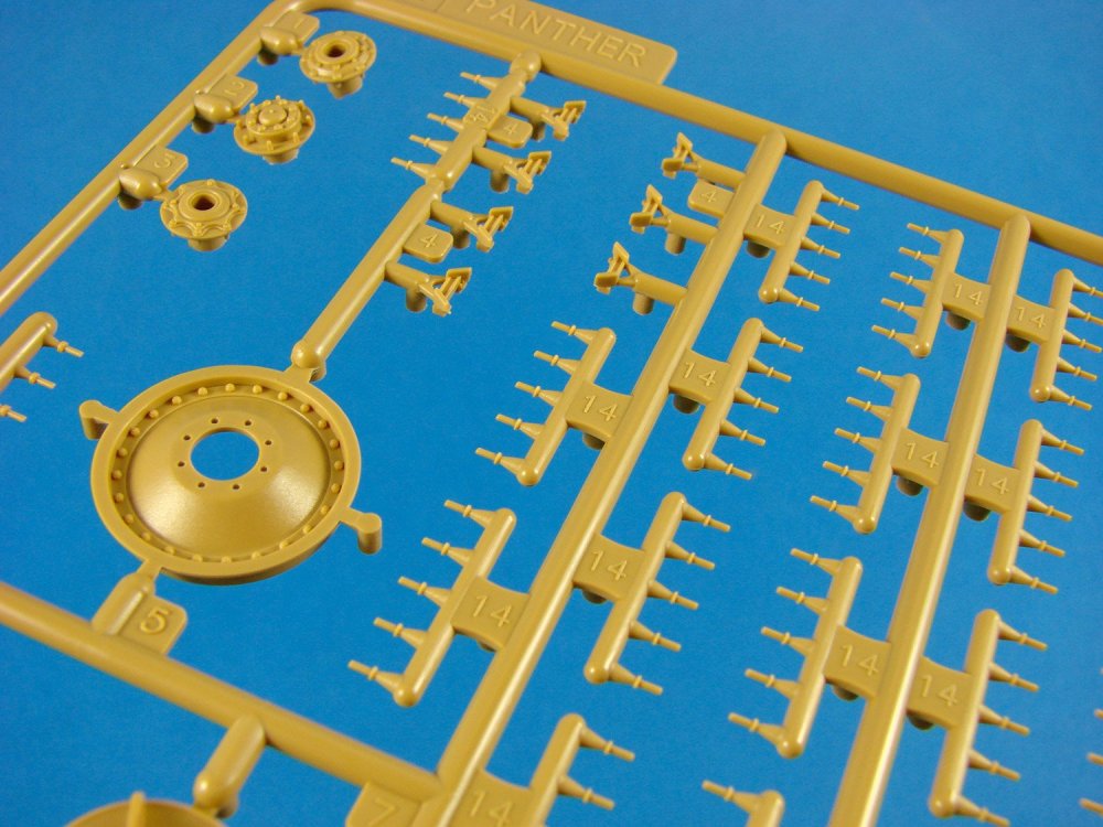
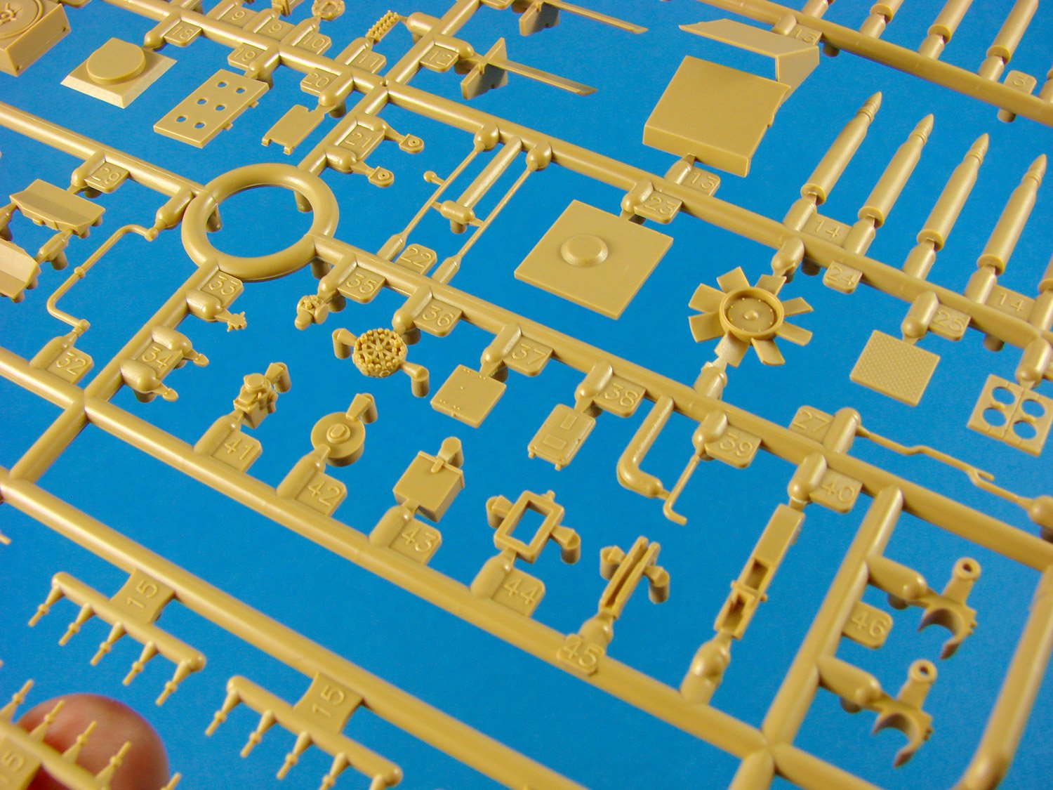
Sprue E & X (x2)

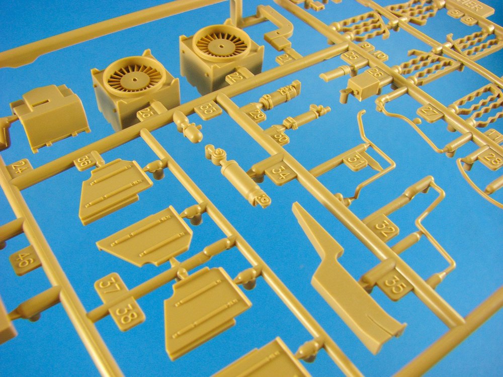
Both of these sprues are supplied connected, and there are two frames included. The most obvious inclusion here are the many shells that will be distributed around the hull interior. That much explosive in one space must’ve played on the minds of the crews. Note also a jig for building the tracks, and the multitude of track pins. The individual links are first sat on the track jig and then each bank of pins is installed whilst on the sprue. When in situ, the sprue will then be removed. Genius! Other parts here include wheels, engine fan amongst many other small components.
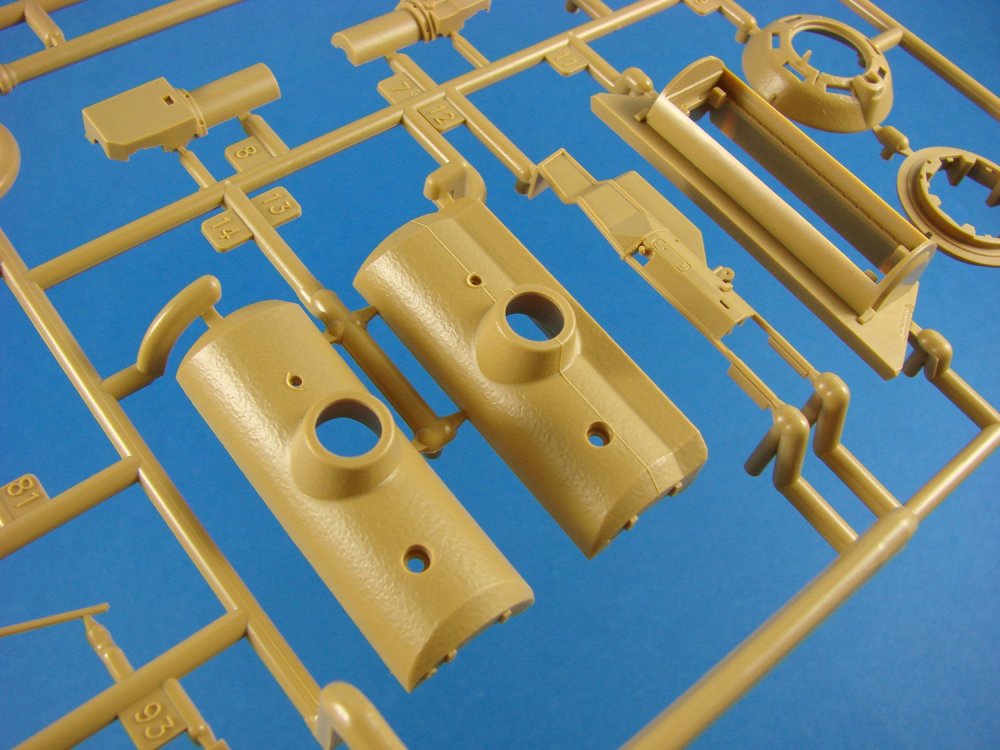
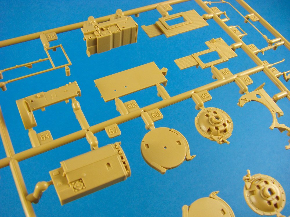
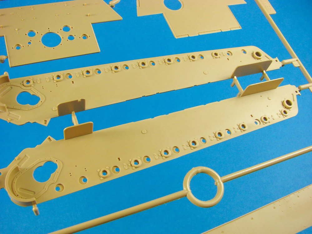
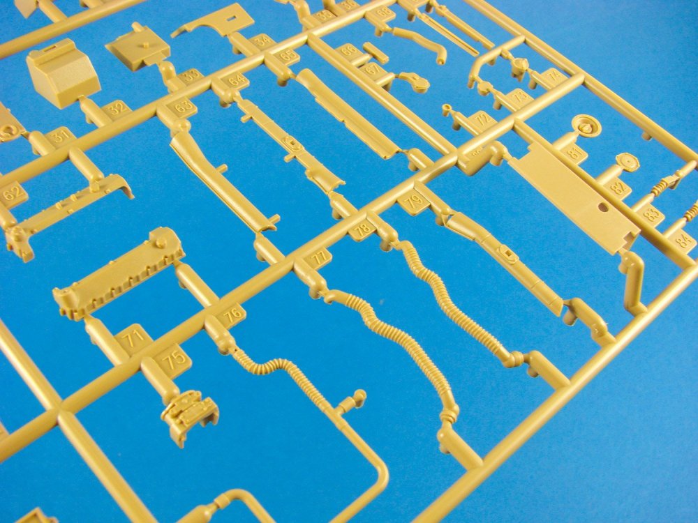
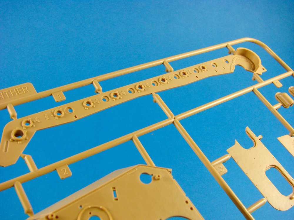
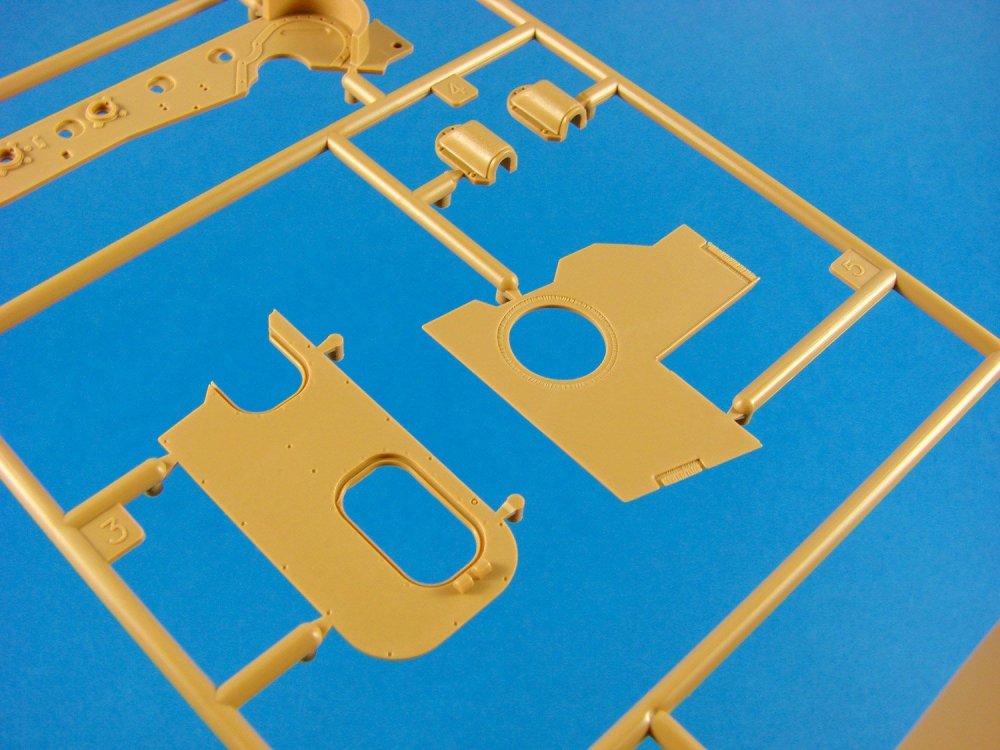
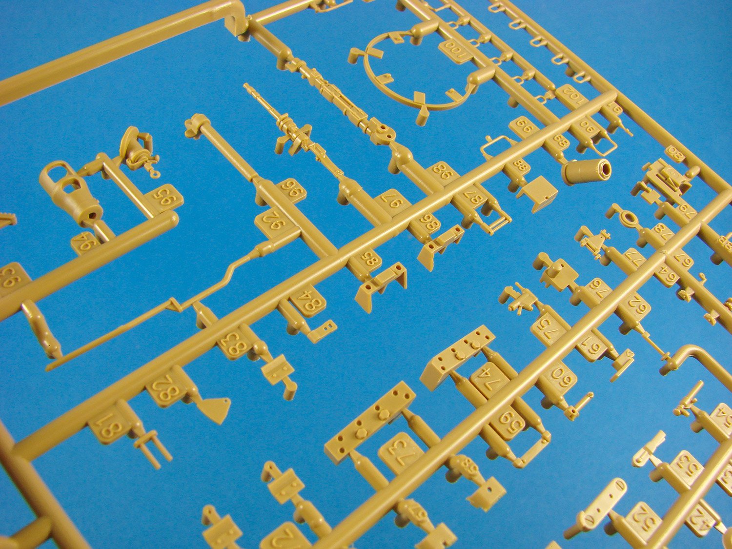
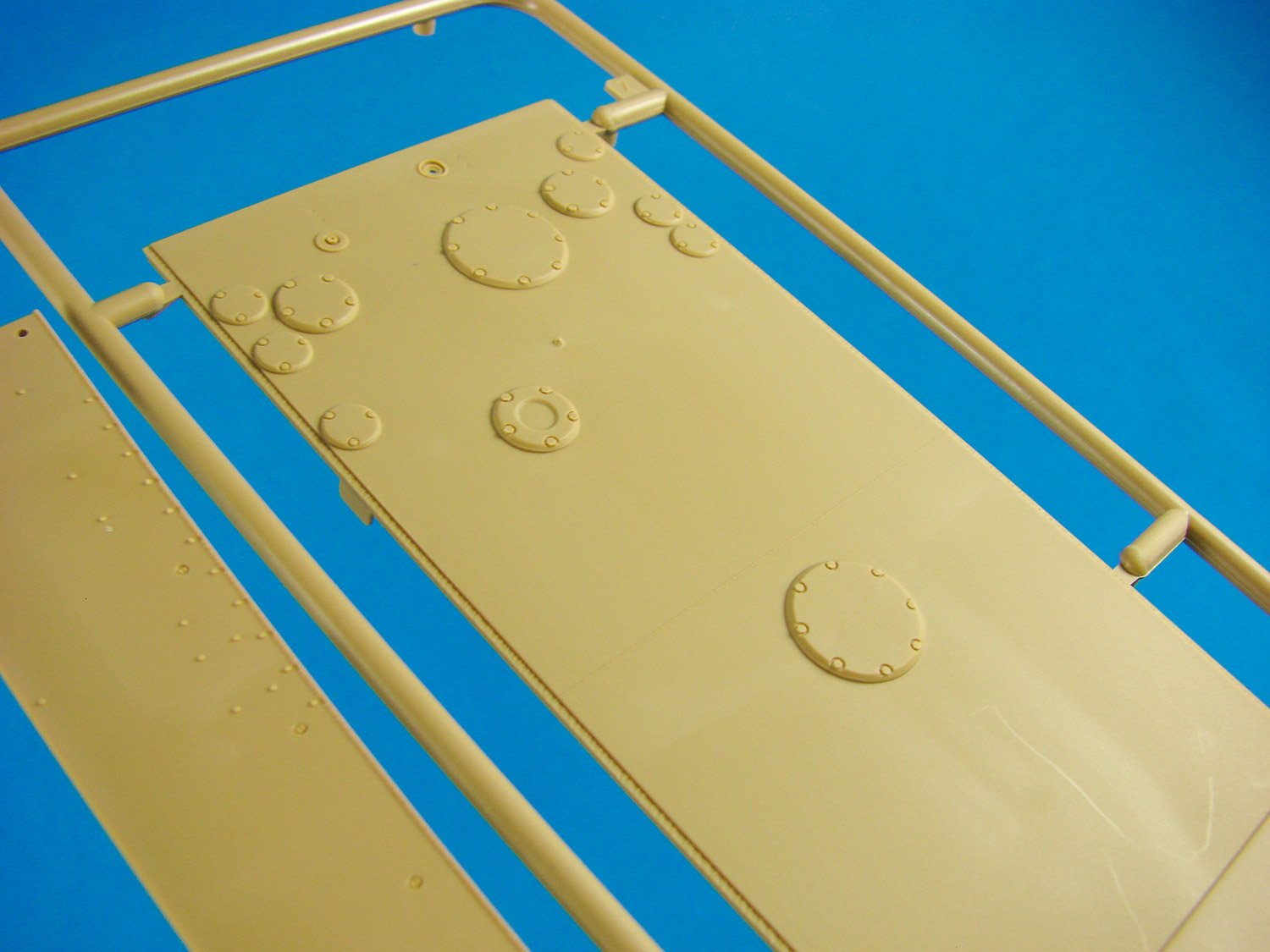
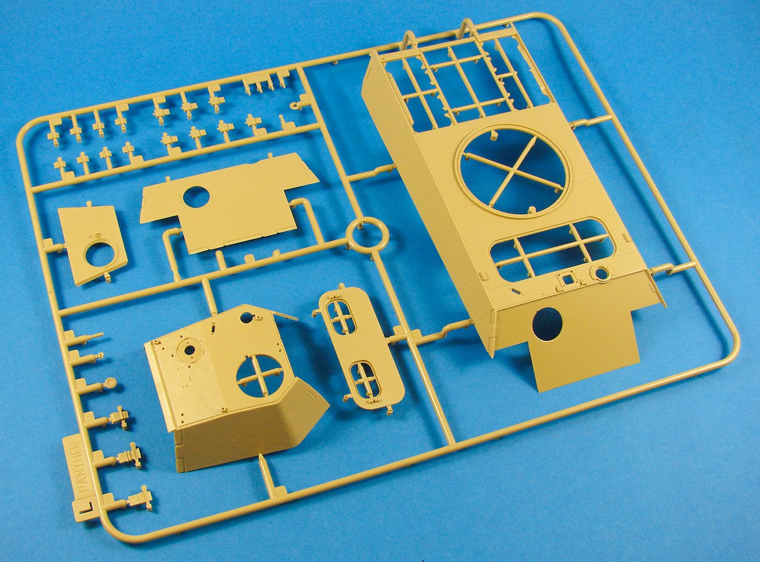
Sprue F
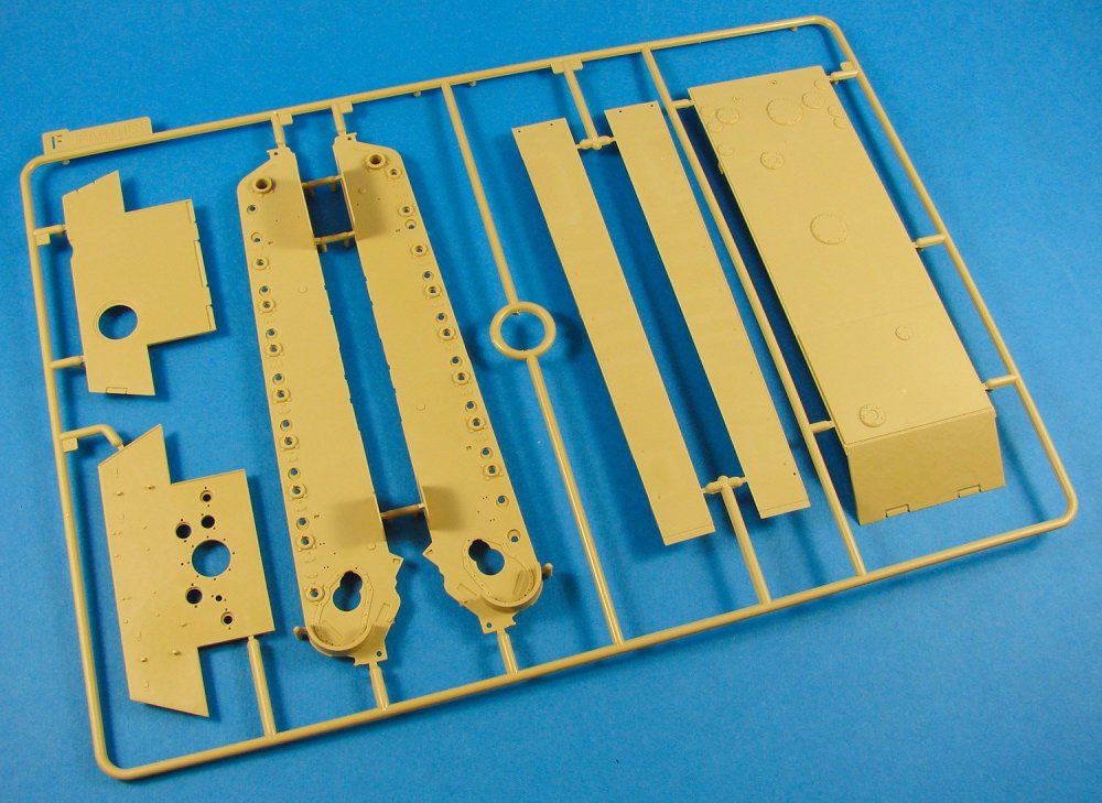
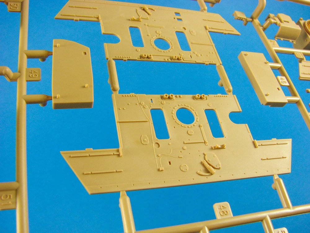
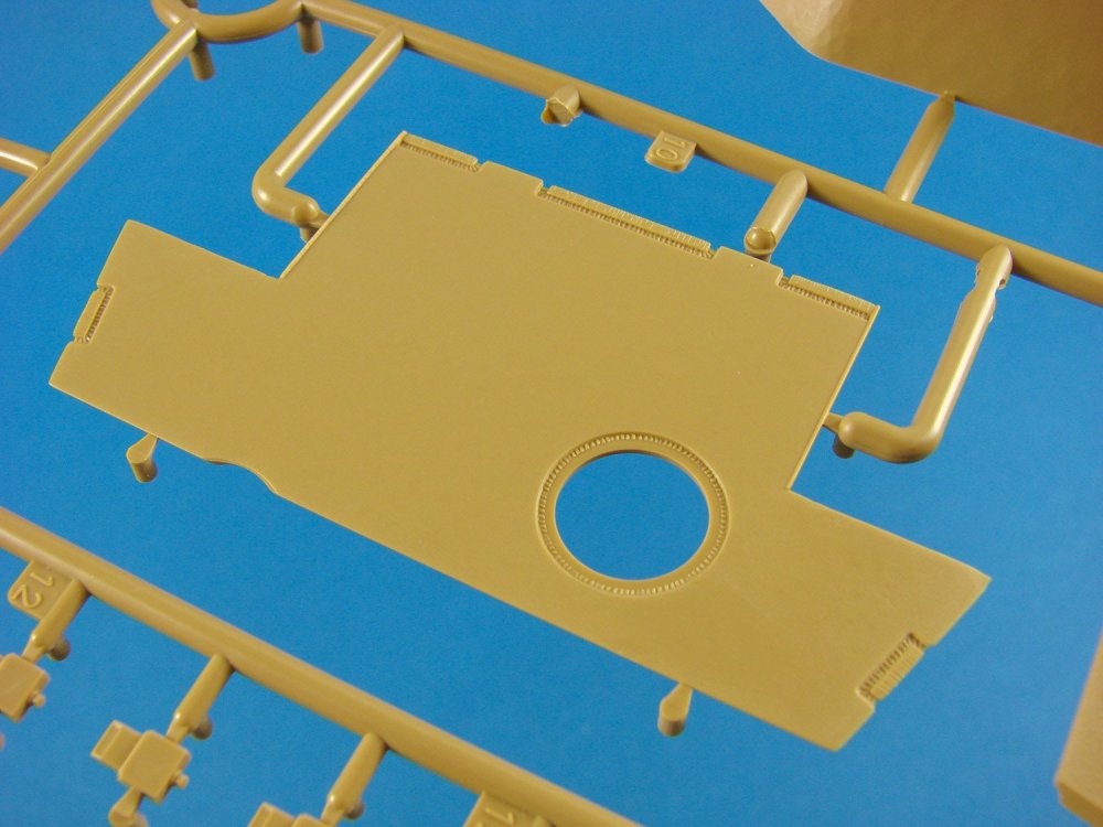
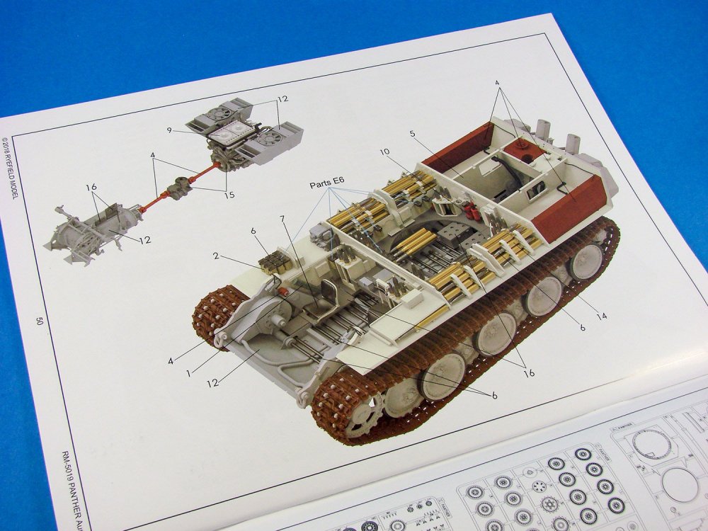
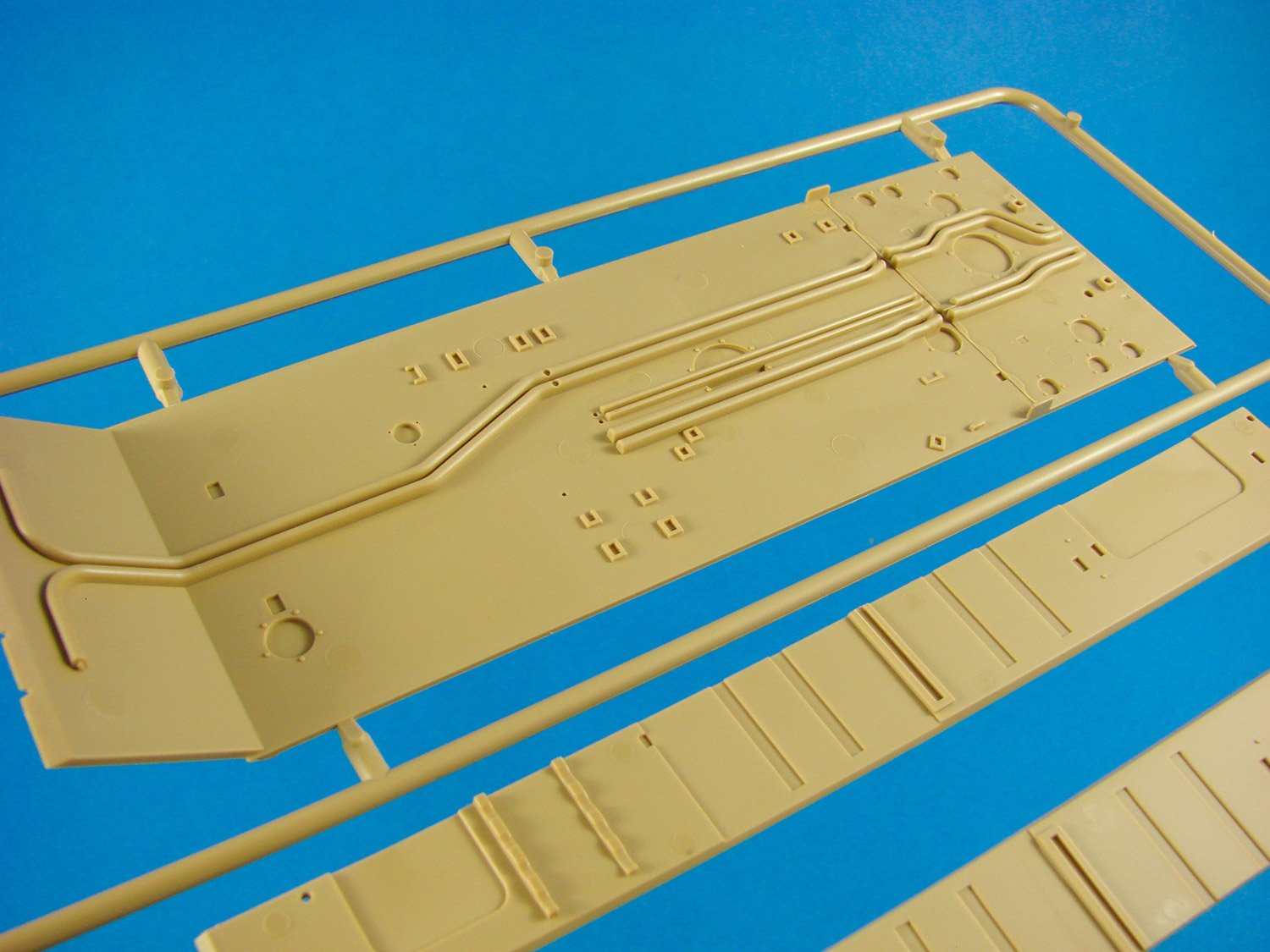
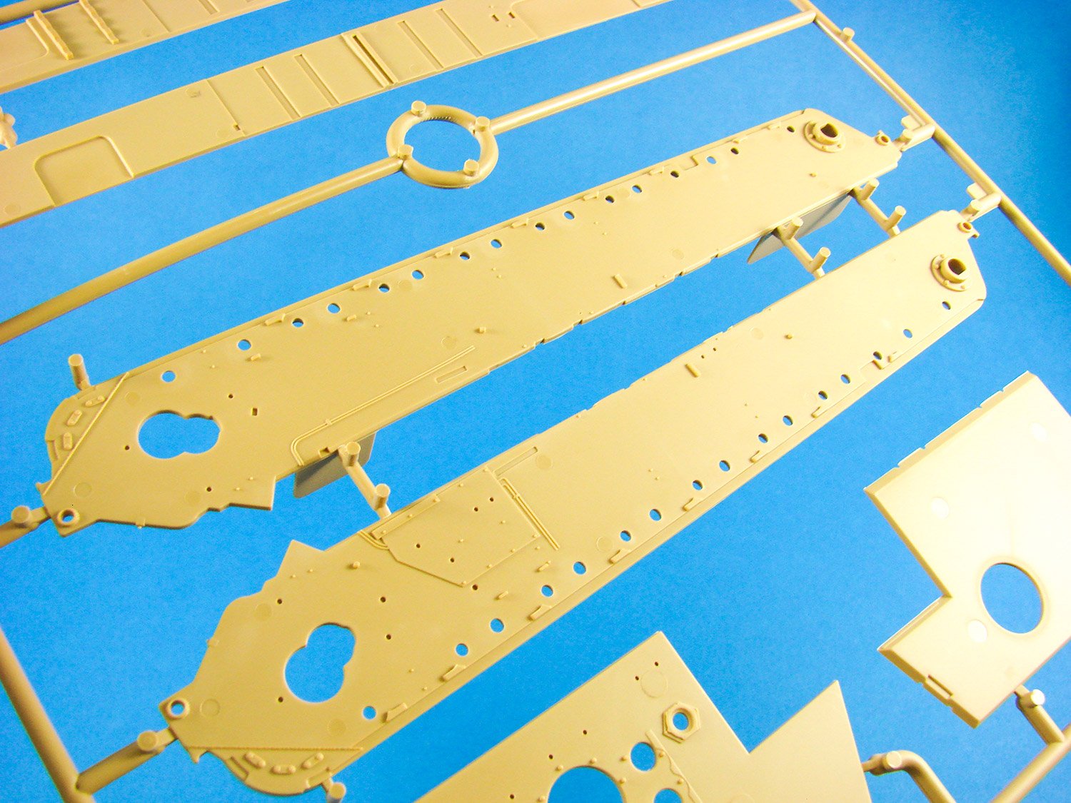
This sprue provides the rear and front glacis, lower hull sides, fenders and the hull floor. As this kit has a full interior, the hull floor has details moulded within. Detail is excellent, especially on the hull sides. Some very nice weld seam details to be seen too.


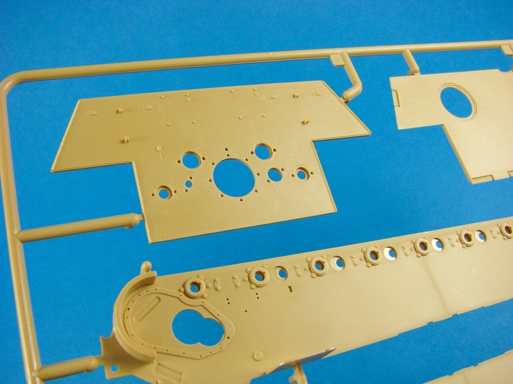
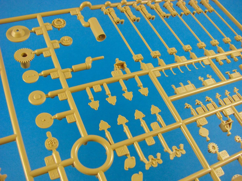
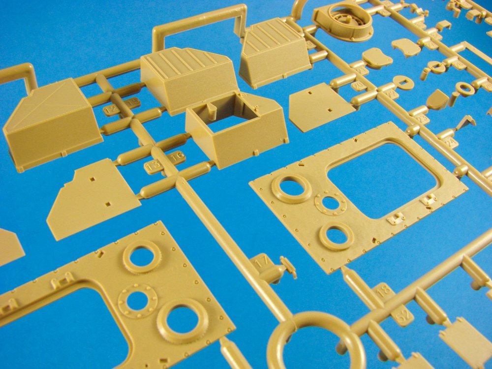
Sprue G
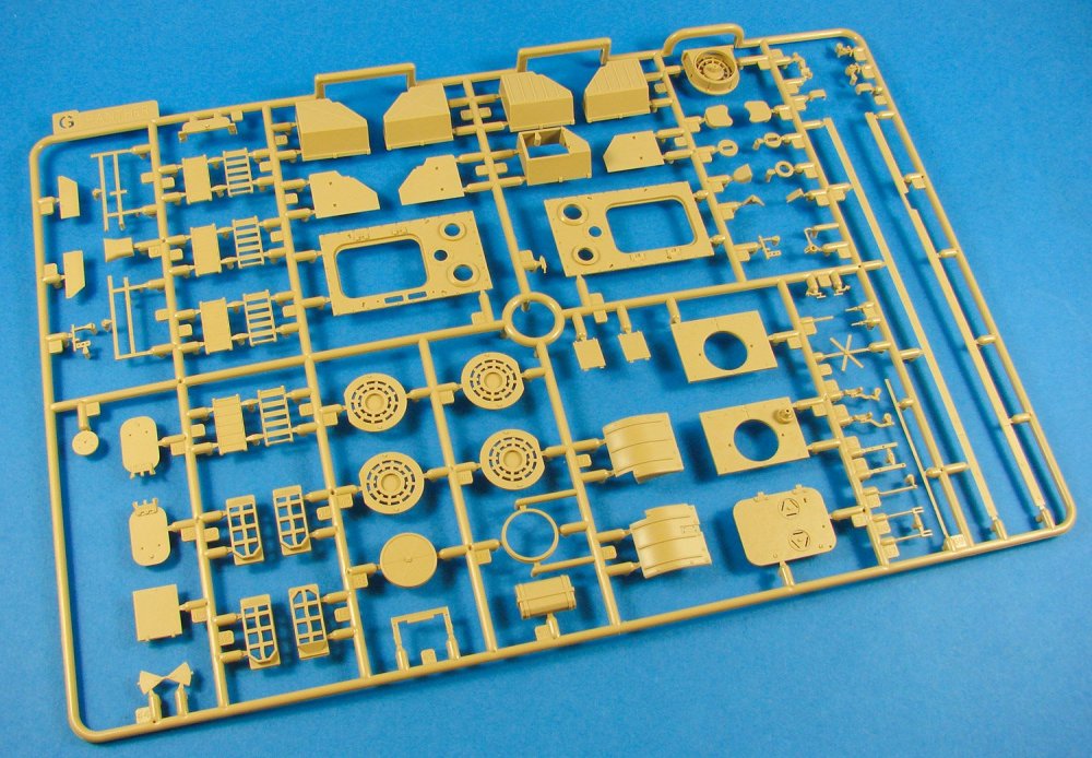
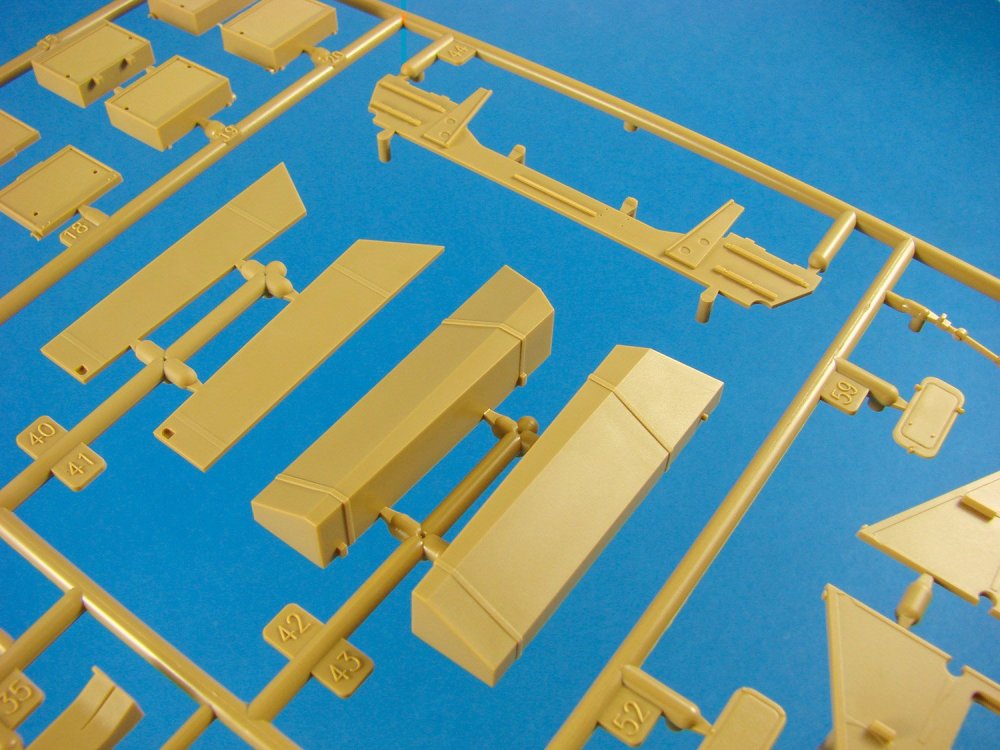
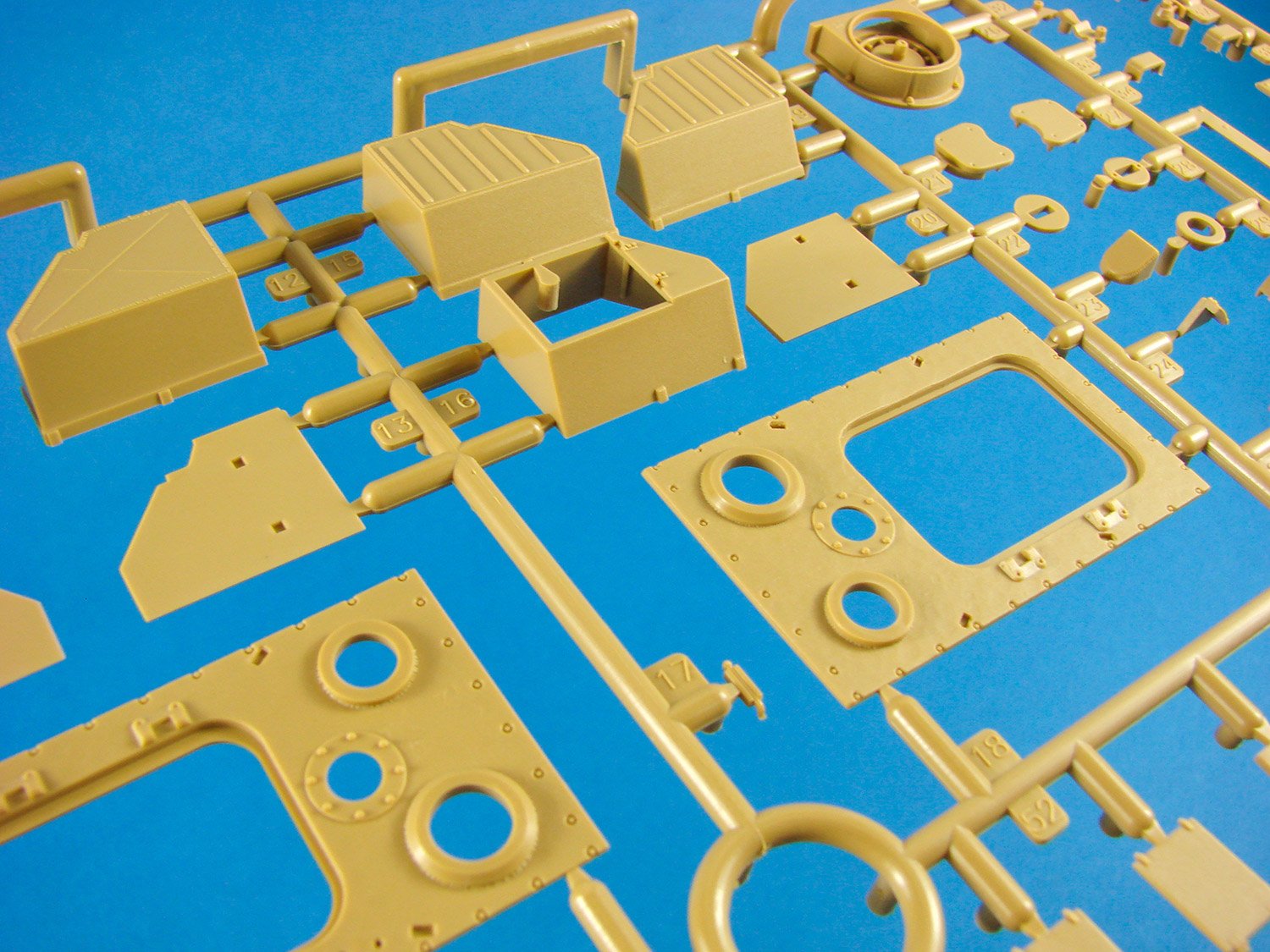
Many items here that appear to be associated with the rear engine decal, with numerous options provided, such as those for the four different permutations of exhaust layouts, heaters, tool racks, access doors (poseable), front fender mudguards etc. Note also options for the rear stowage bins.
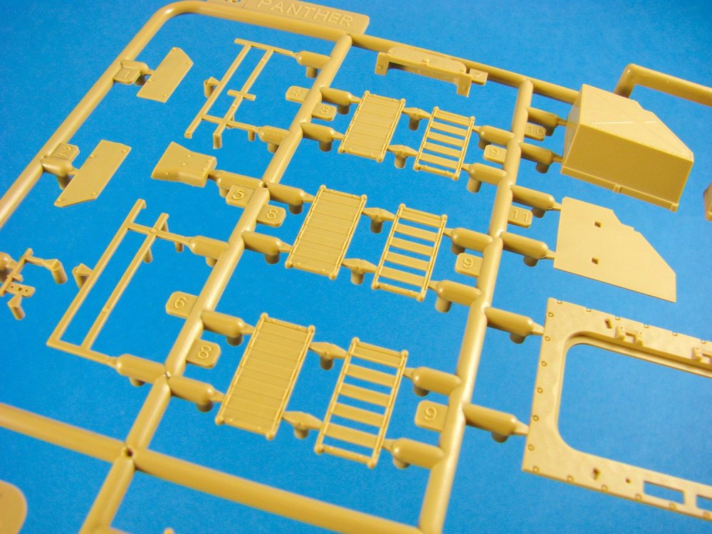
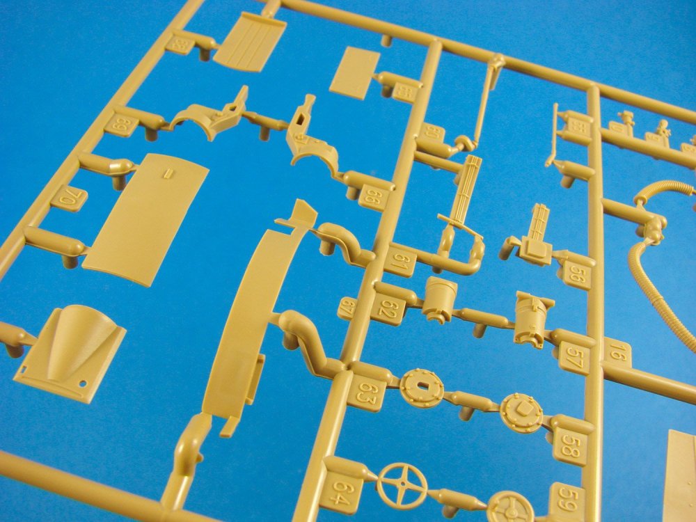
Sprue H
This Panther kit can be fitted with the heated duct system as an option. This means that RFM needed to be able to enable the modeller to easily install these parts. Note here two internal bulkhead options which provide the means to display the model with or without the heat duct system. Certainly better than having to mod the part yourself. Internal rear compartment walls, shell racks, lower hull central floor, fuel tanks, filters etc.

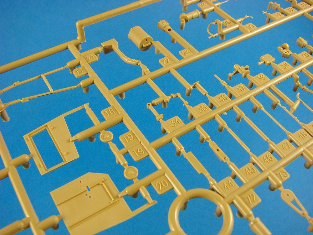
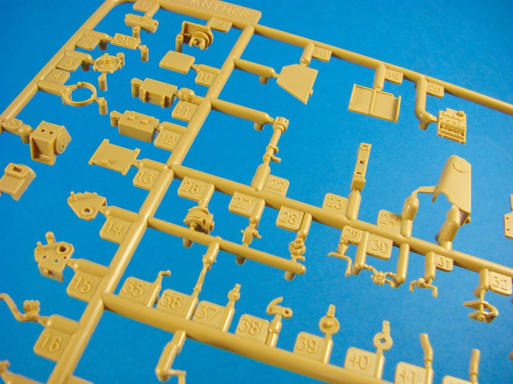
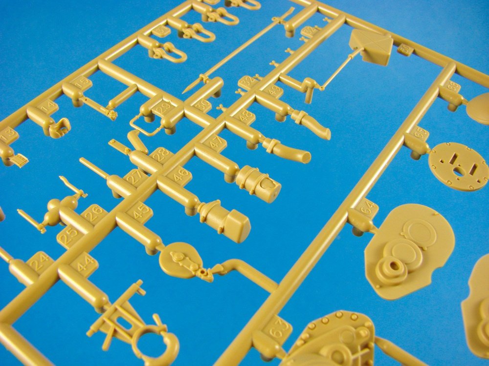
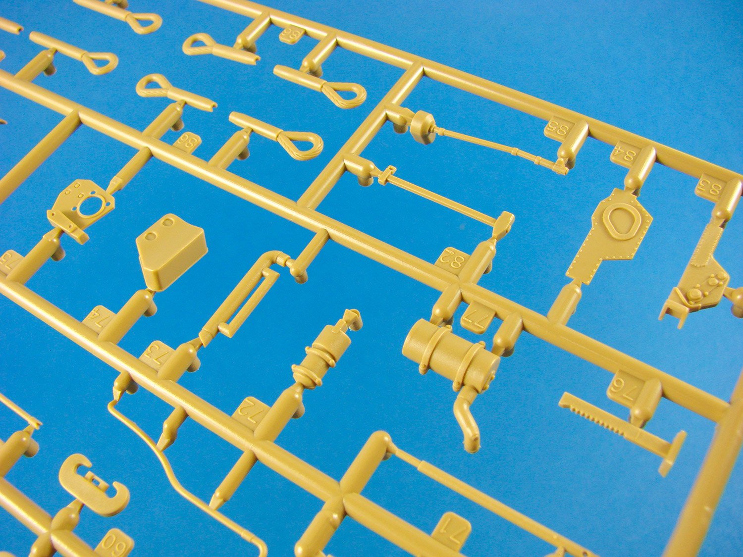
Sprue J
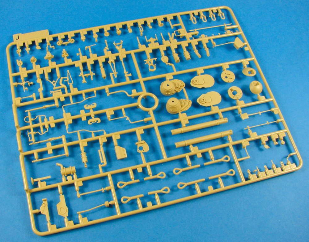
Another multitude of small and key components to be found here. Everything from the 20T jack (that can be posed deployed or stored), drive gear housings, rear glacis parts (including towing mechanism), hull tools, towing cable ends etc.

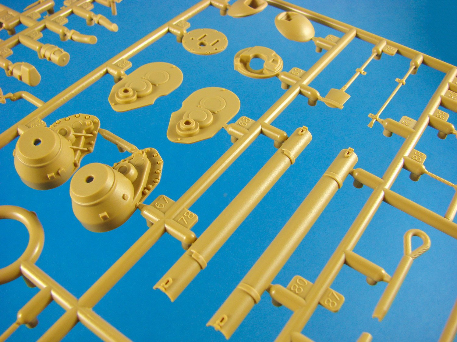
Sprue K
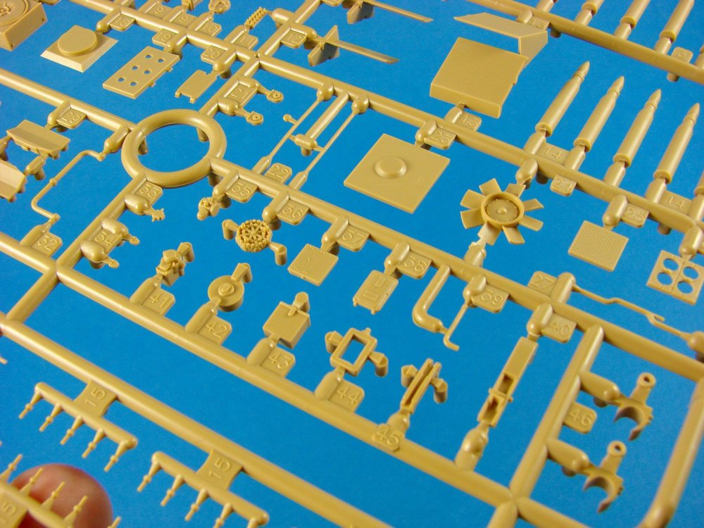
Here you find the mighty Maybach and other associated parts. A variety of other components are moulded here too, such as the rear mantlet plates (two options), ammunition storage rack parts, hoses and ducting, radio sets, and the remainder of parts that are scattered around the interior.

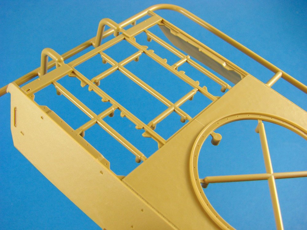
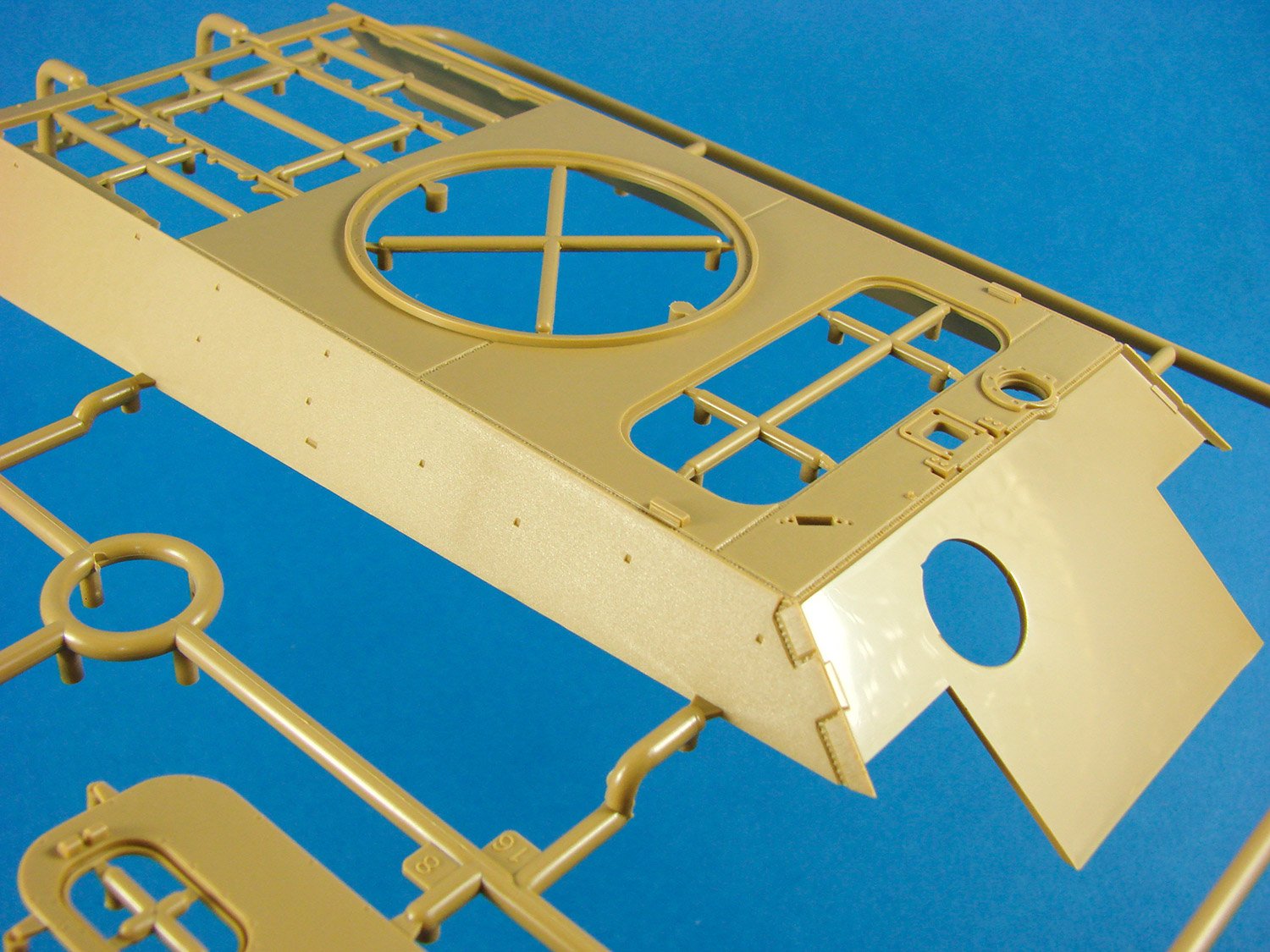
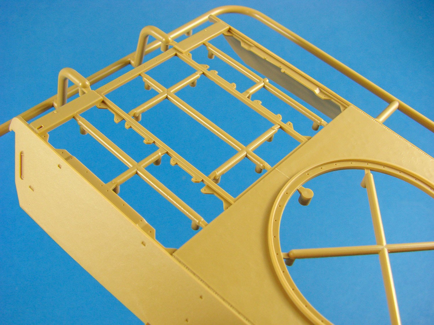
Sprue L
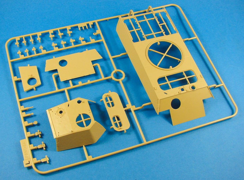
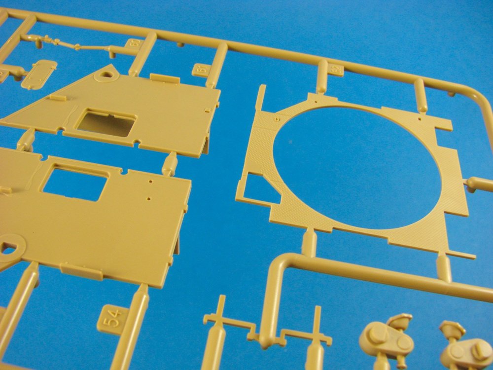
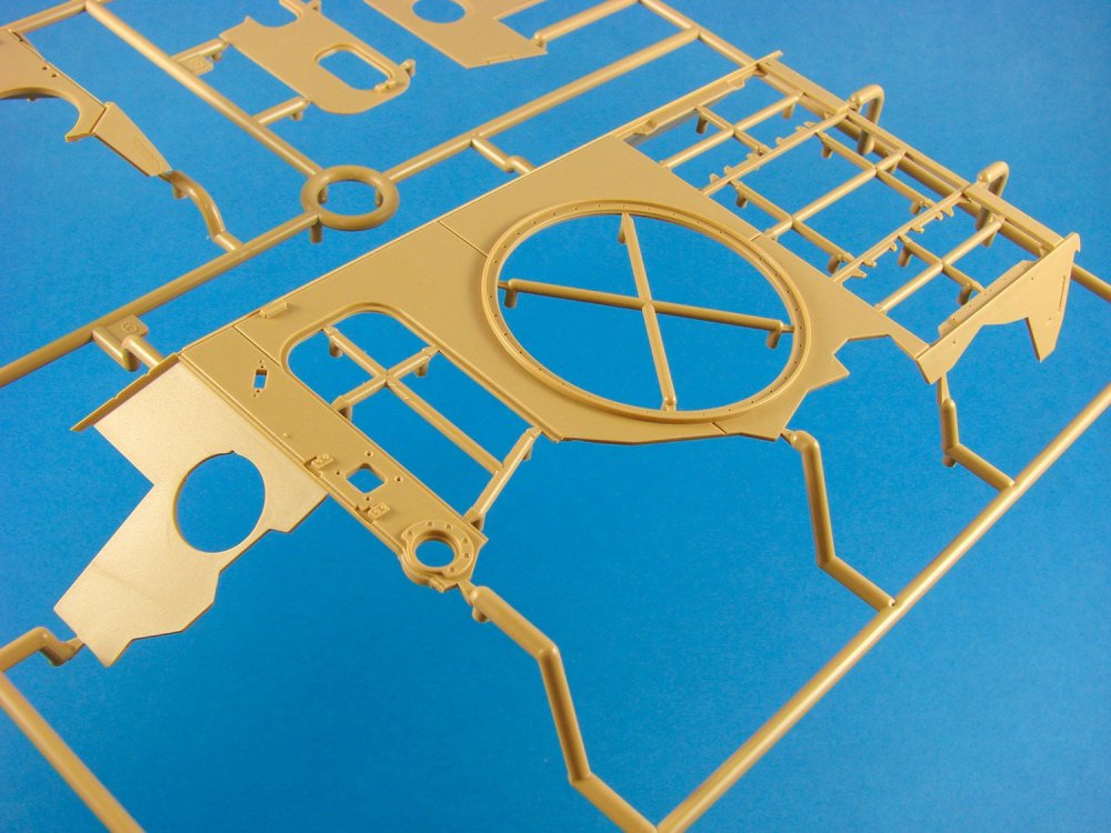
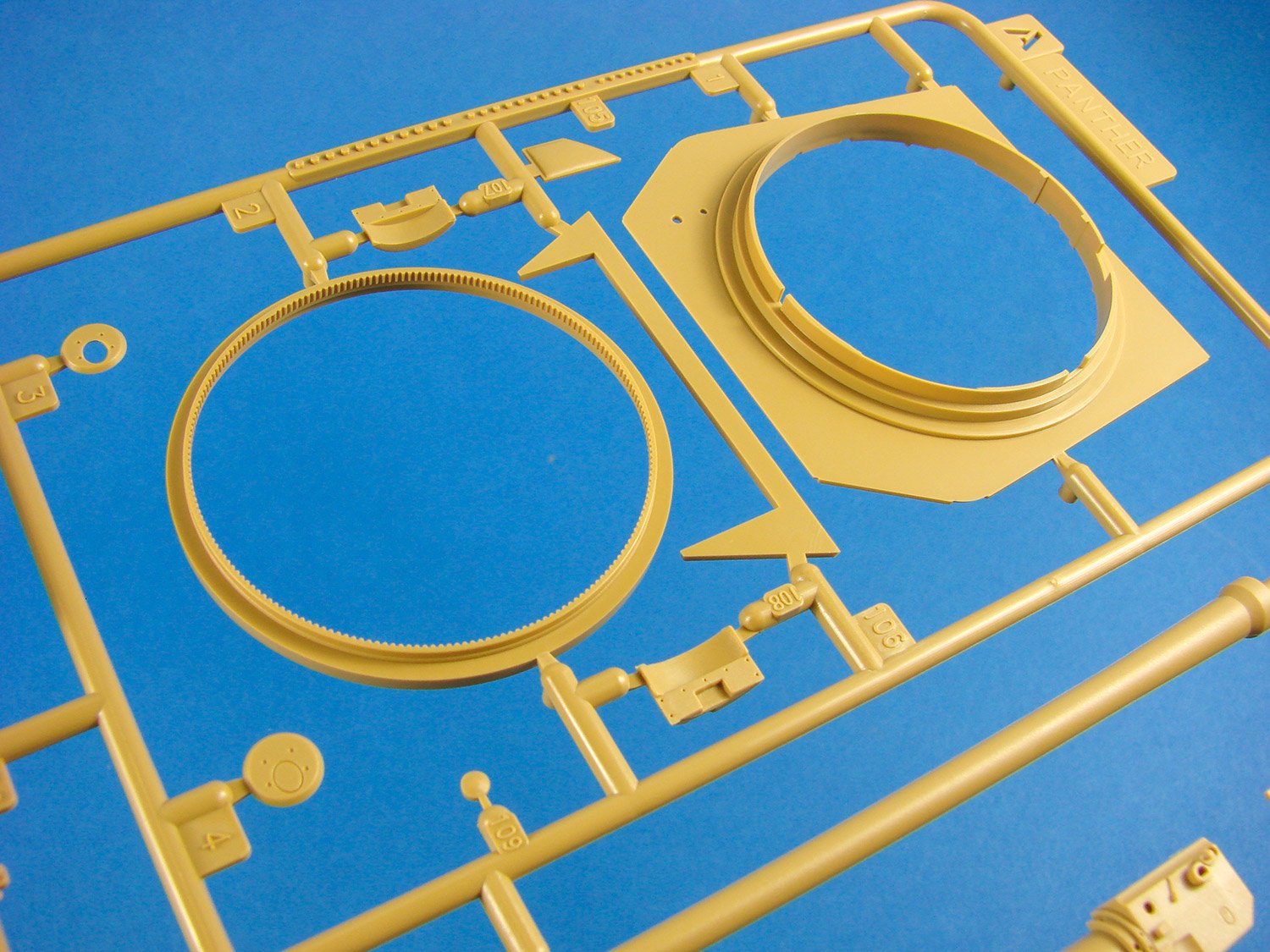
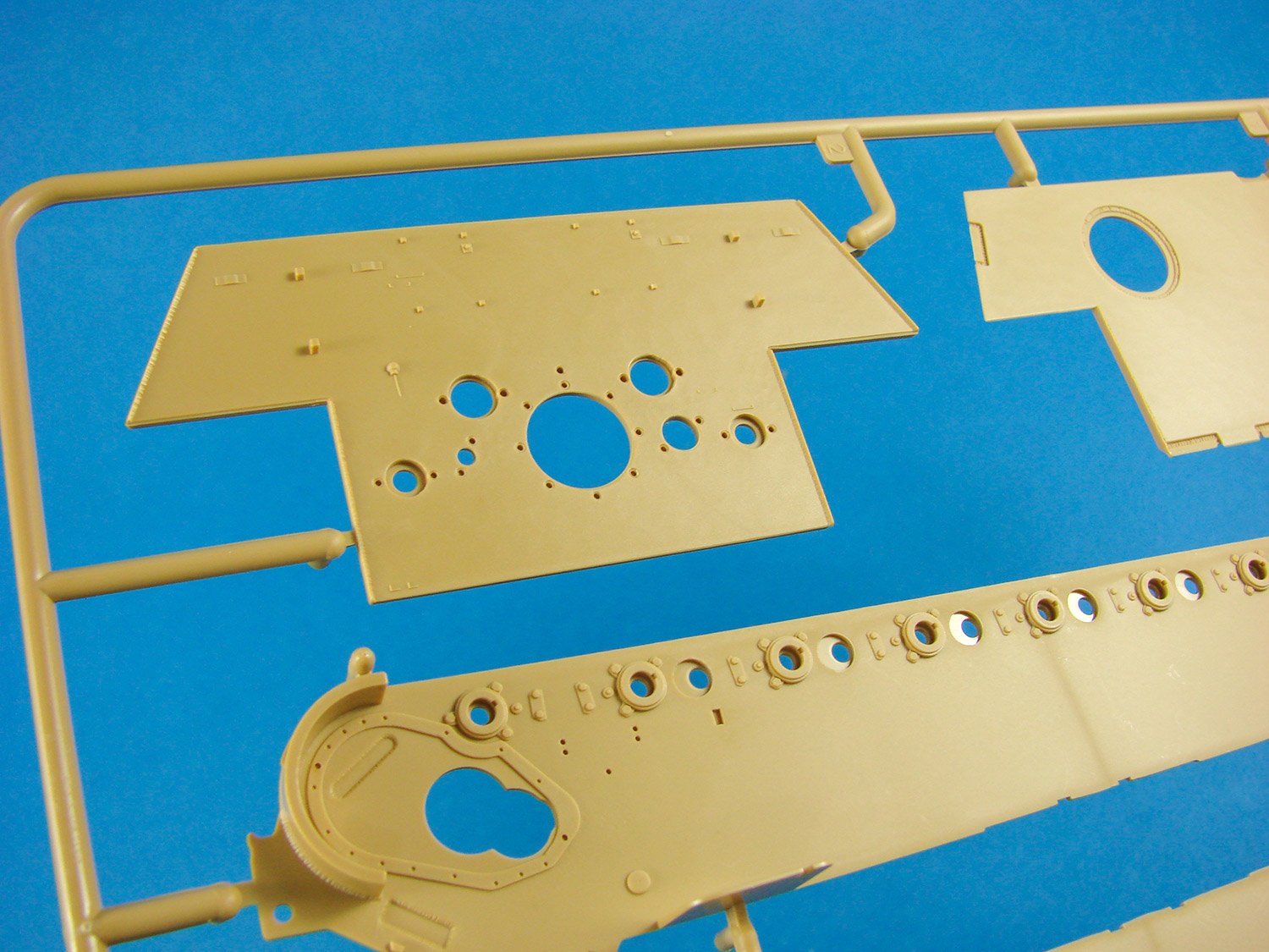
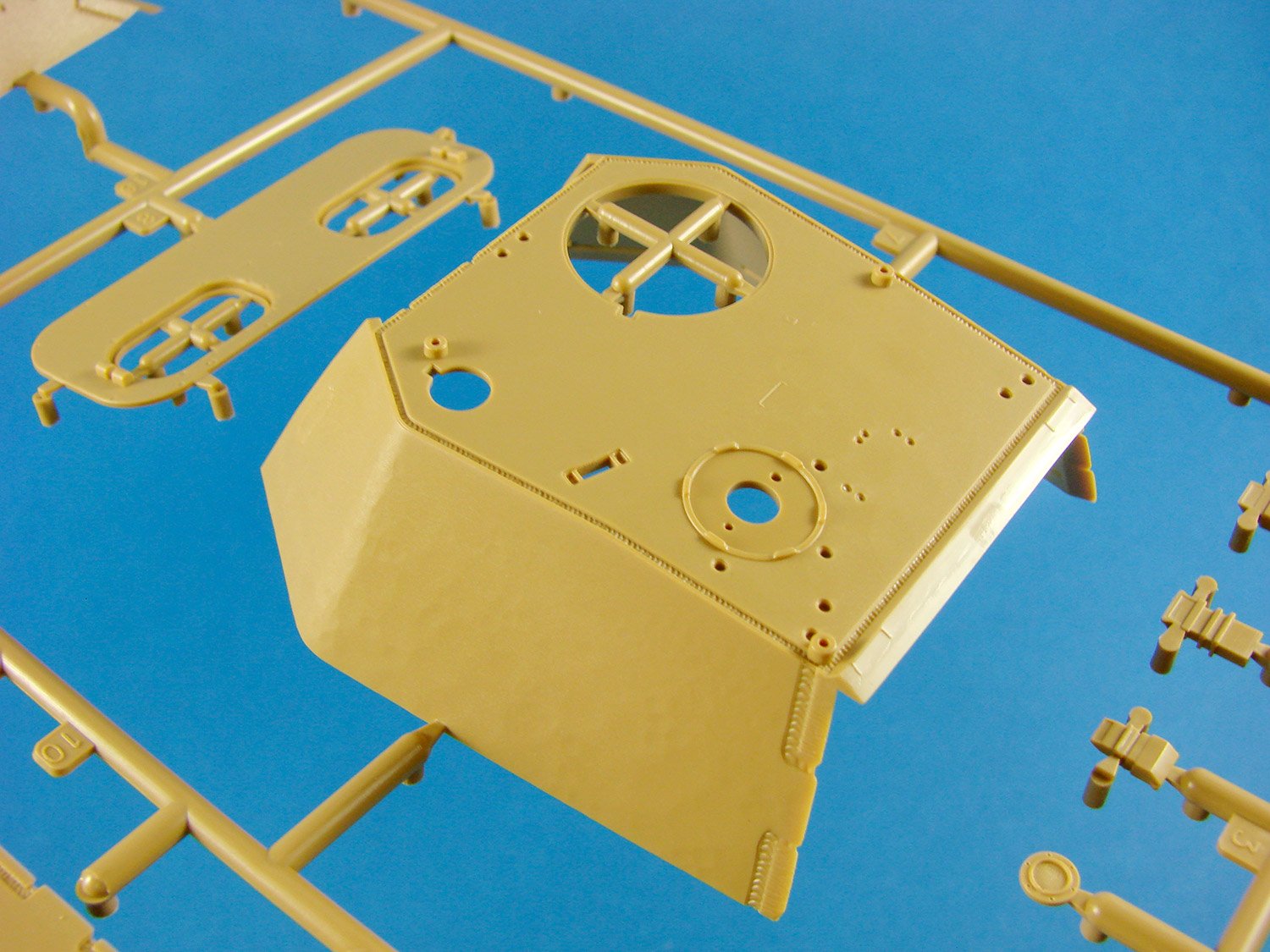
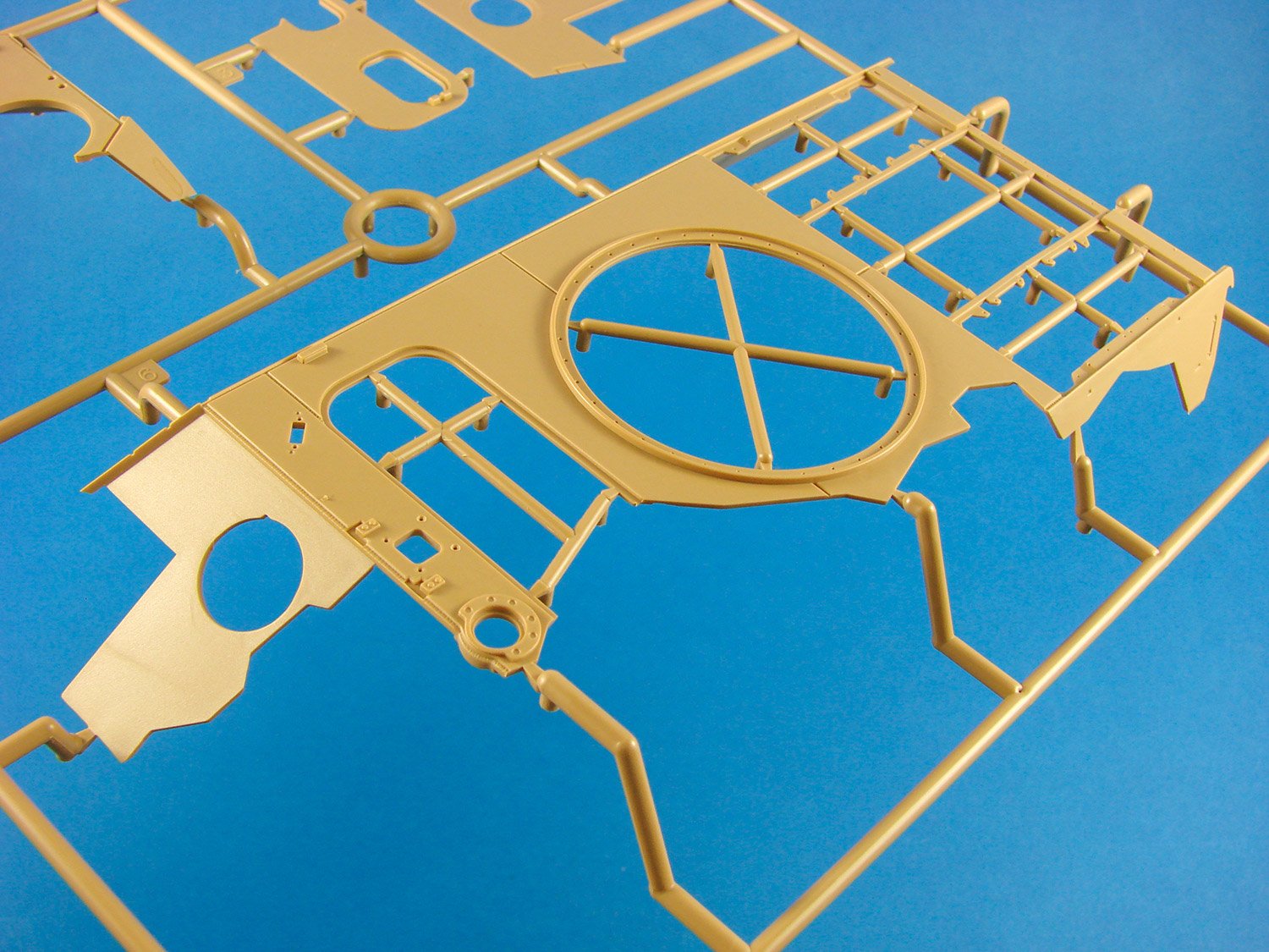
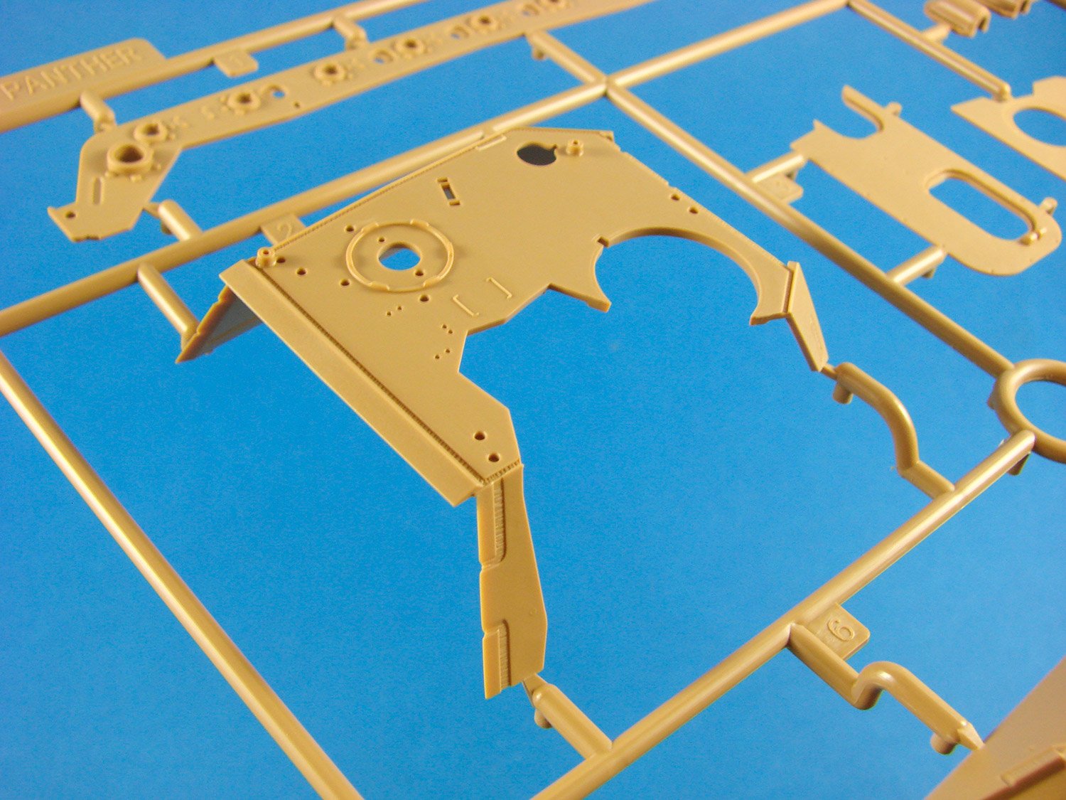
On the original, limited edition release, this sprue was moulded in clear plastic, with the periscopes, so I’m not too sure if the version that superseded that was supplied with the periscope parts separately as clear items. On this sprue you will find the regular upper hull, forward glacis, turret and rear panel. Details are excellent, such as the weld seams and plate depiction. The upper hull is designed so the engine compartment can be displayed either open or totally without panels.

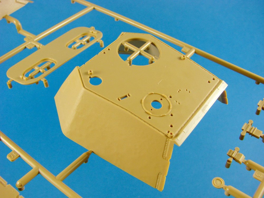
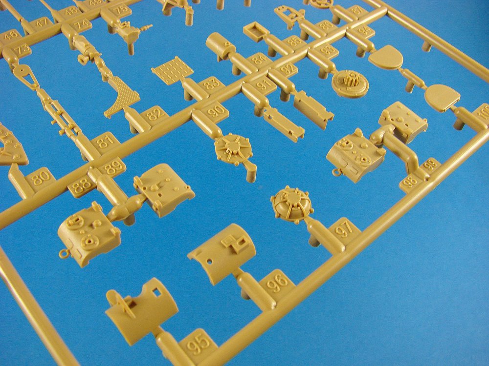
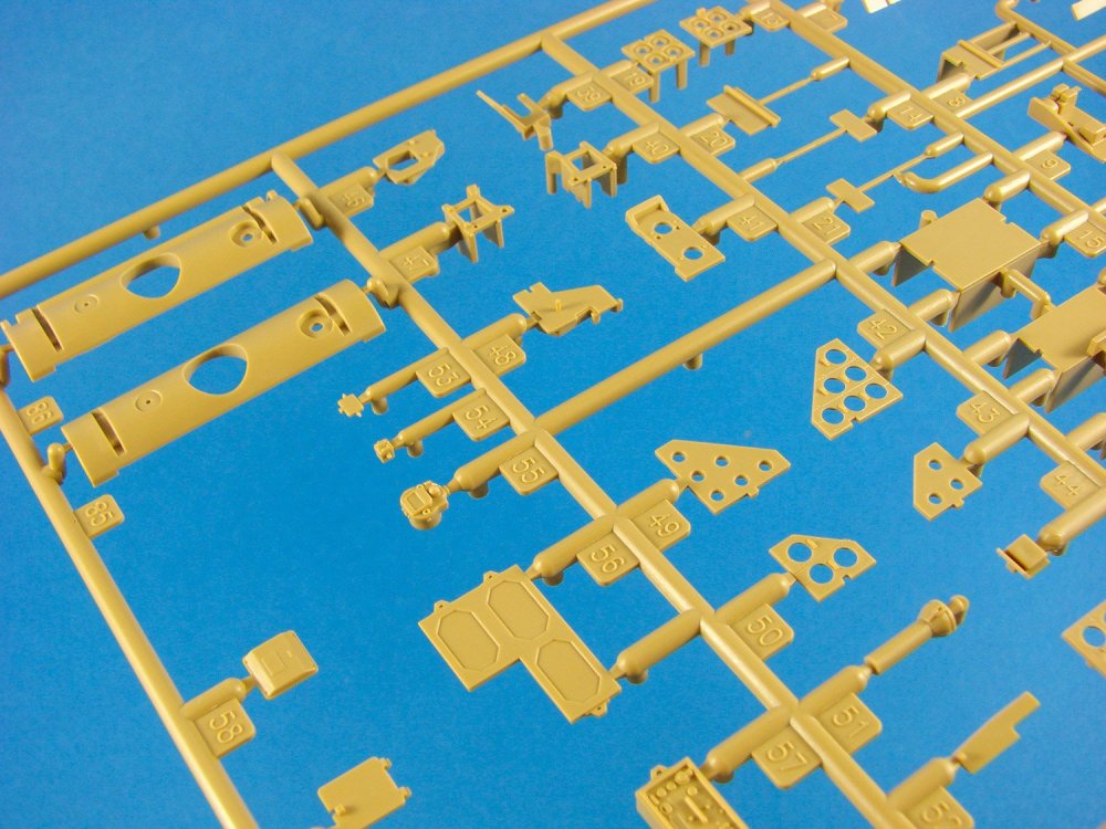
Sprue N
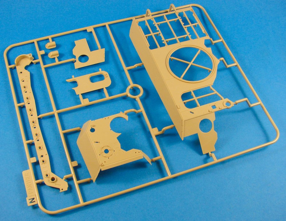
This sprue provides the main rationale for this release, containing a multitude of main parts, but with cutaway areas, leaving everything looking quite odd! RFM has supplied the upper hull, turret, hatch panels and the left-hand lower hull side as candidates for their anatomical study of this big cat.

Sprue P
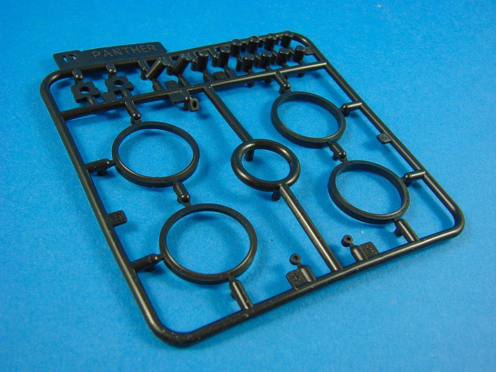
This is a rubberised sprue containing four wheel rims and a series of captive collars for holding the wheels in place on the torsion bar arms.
Sprue T
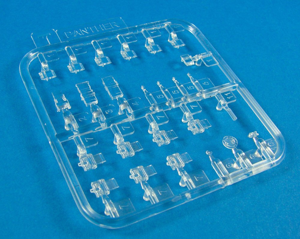
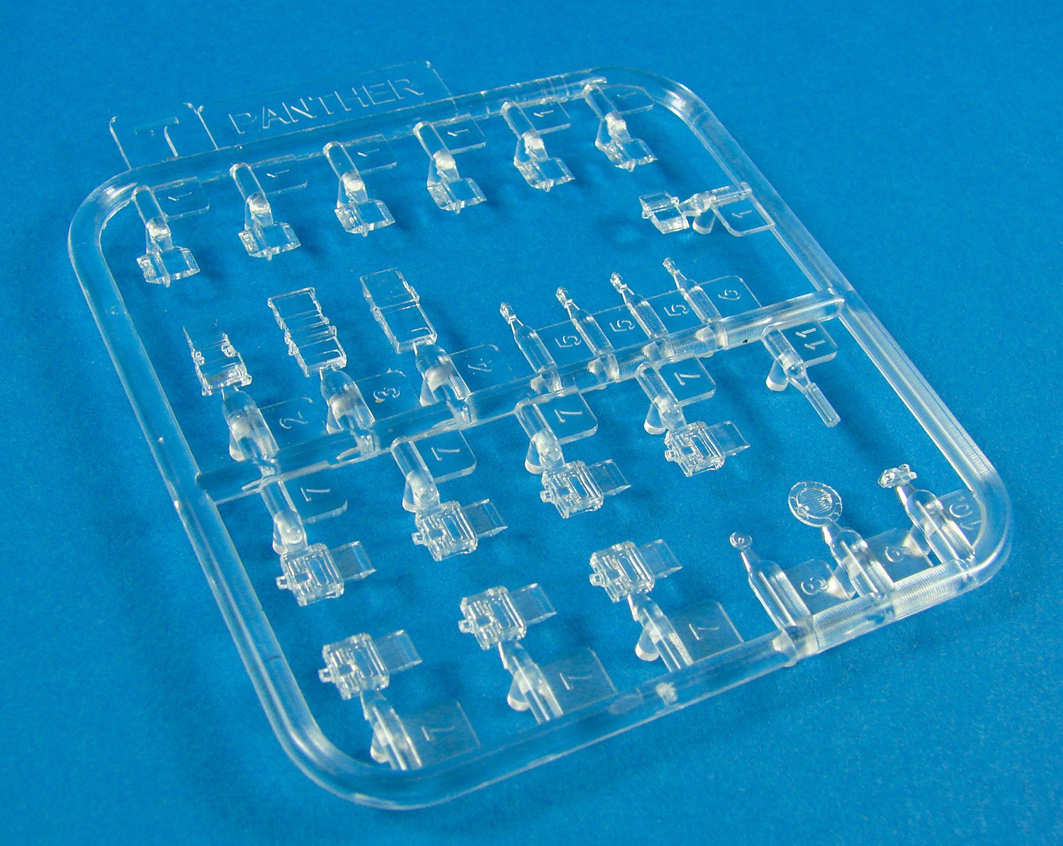
The single clear sprue provides the periscope parts etc. Beautifully moulded, this sprue is distortion-free and with the gates placed on the sides of the body of the periscopes and away from the lenses.
Tracks
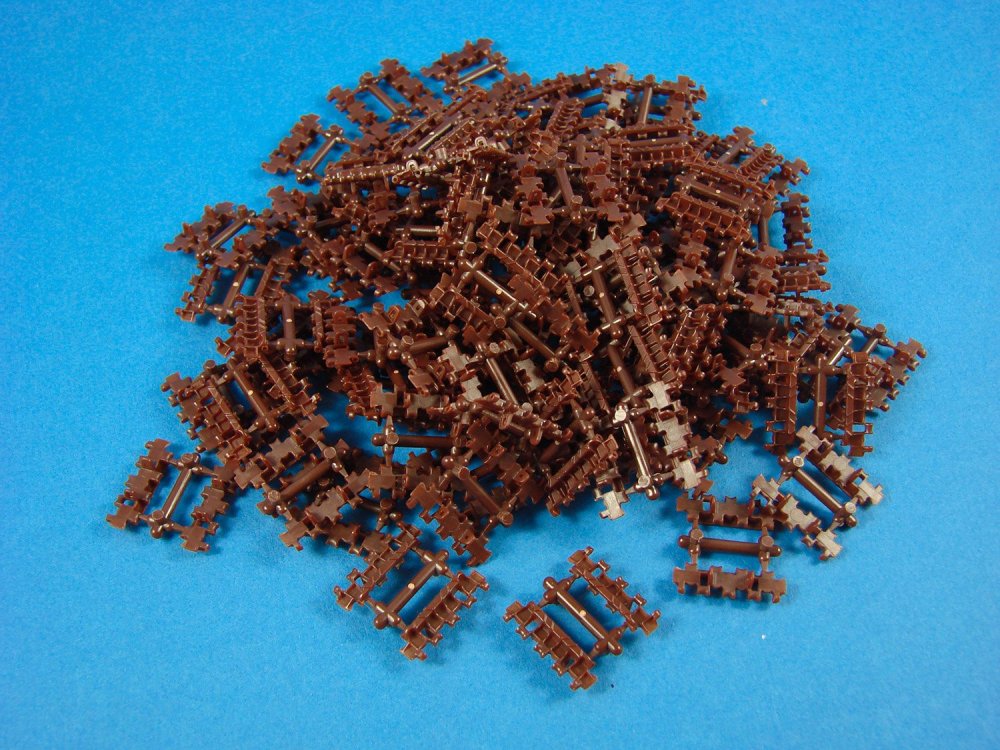
Moulded in a dark brown plastic, these are moulded in twos, interconnected with a small sprue. There are 85 each of these, totalling 190 separate track links. I can’t comment on how easy these will be to assemble at this stage, but they look straightforward enough with the supplied jig and method of applying the track pins that I mentioned earlier.
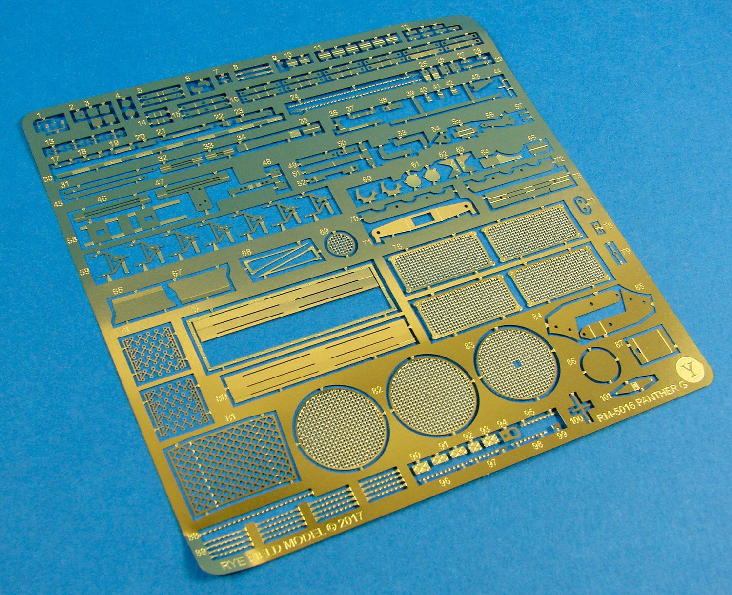
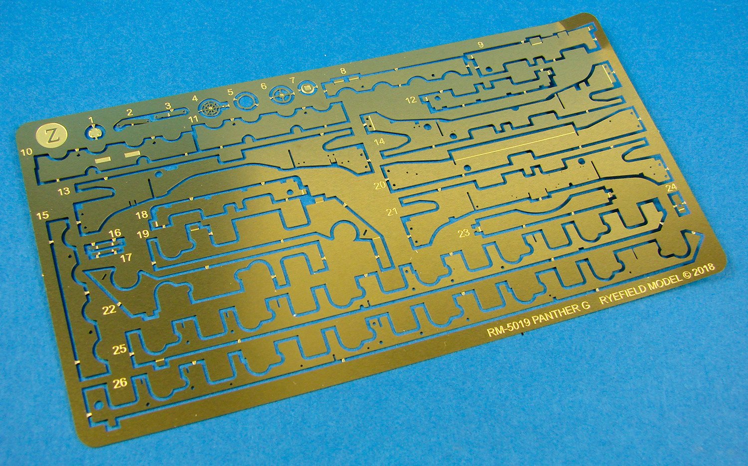
Photo Etch
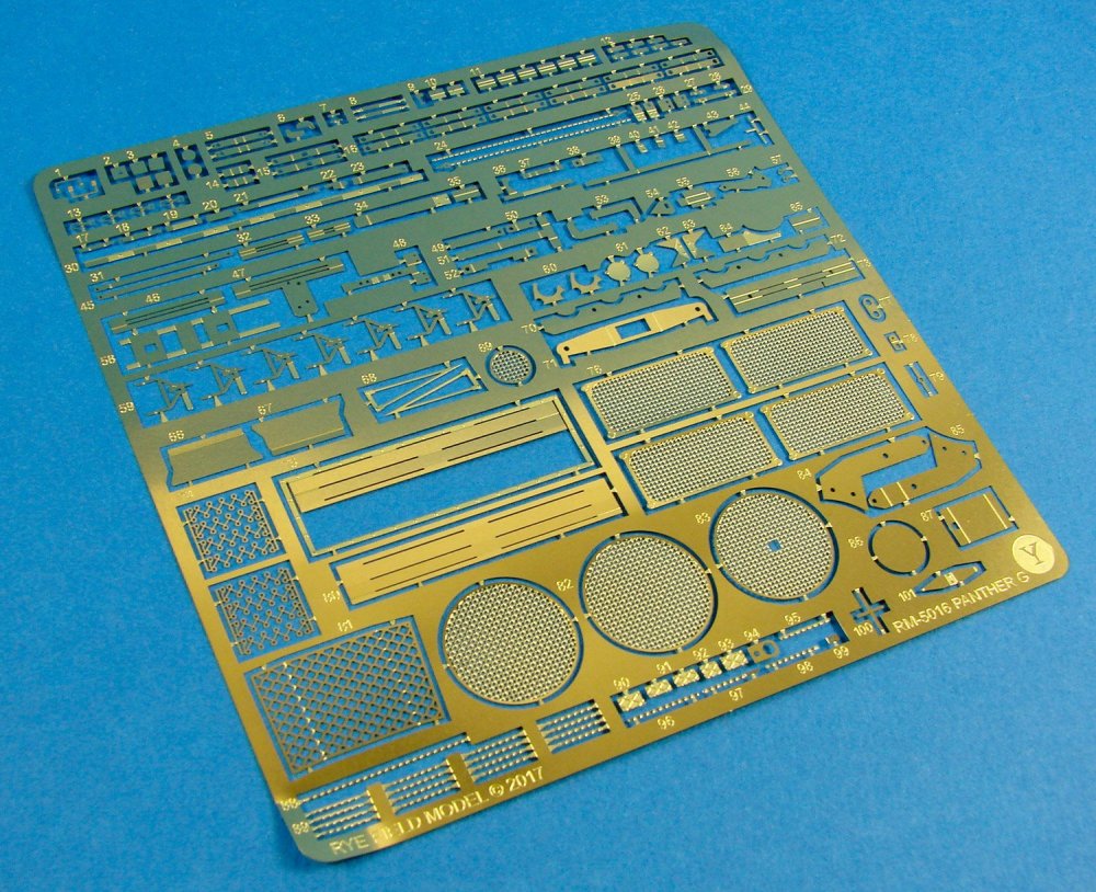
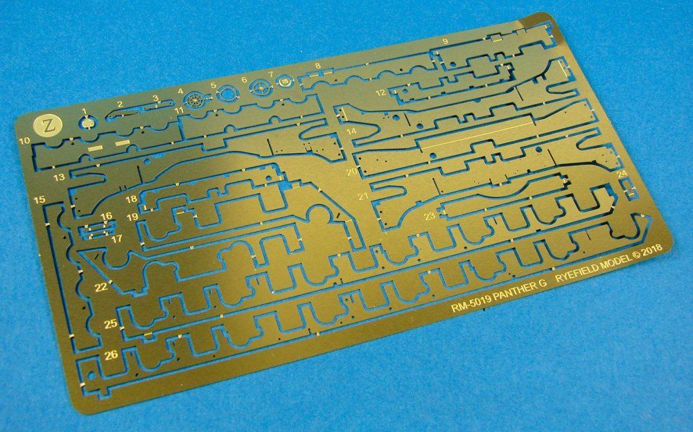
Two frets are included in this release, packed into a wallet with a card protector. Quality is excellent, with narrow part gates that will make it easy to remove and clean the individual components. Included in PE form are the heater grilles, internal hull lower chassis frames, clasps, etc. There are a lot of parts to keep you occupied.
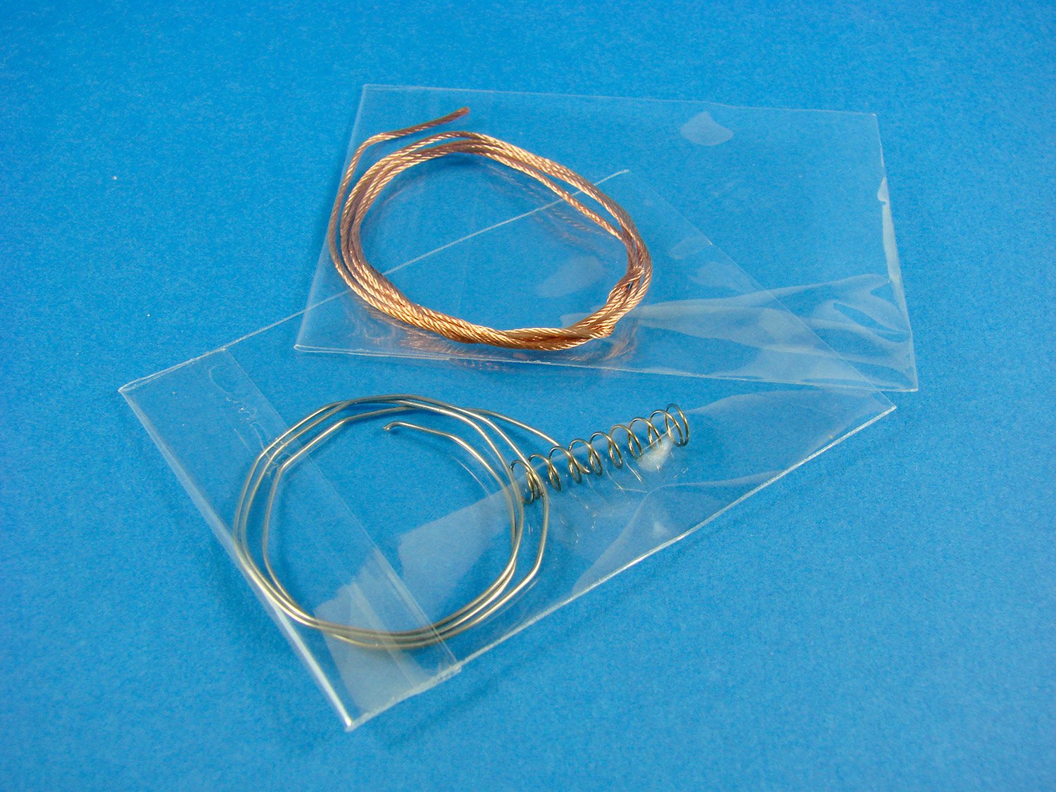
Extras

Only a few bits here, namely braided copper wire, lead wire, and a spring for the main gun recoil.
Decals
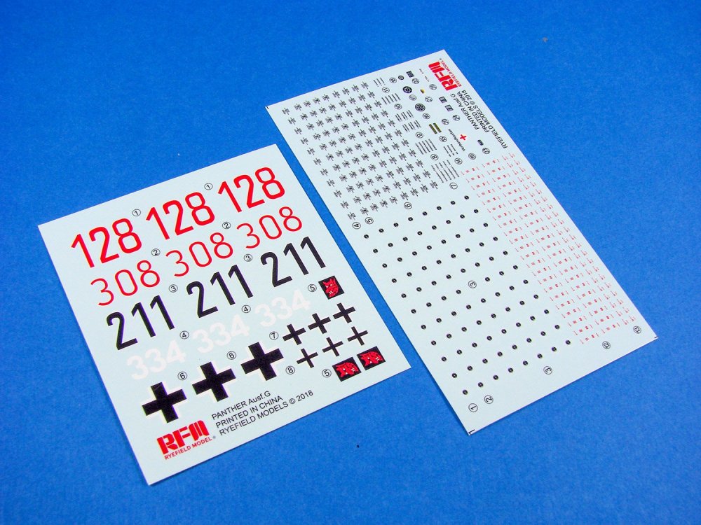
A single sheet is included with decals for the three schemes included. A whole load of stencils are also included. Printing is excellent, with the decals being nice and thin and with minimal carrier film. Colour is solid and in register.
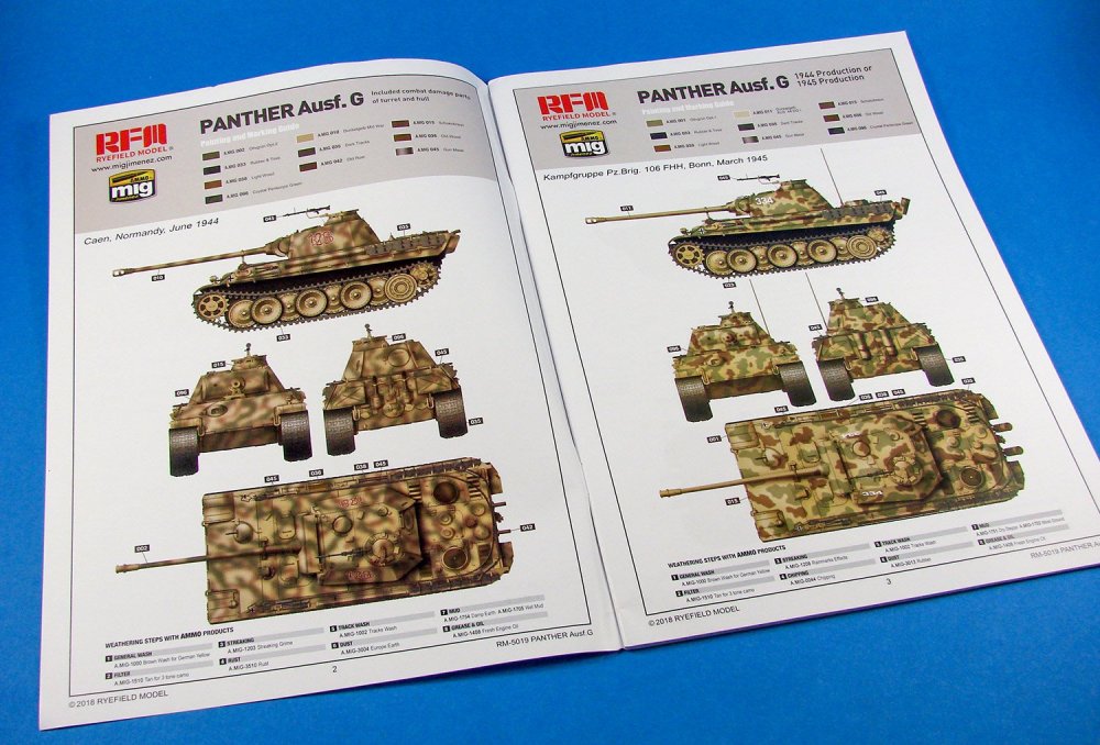
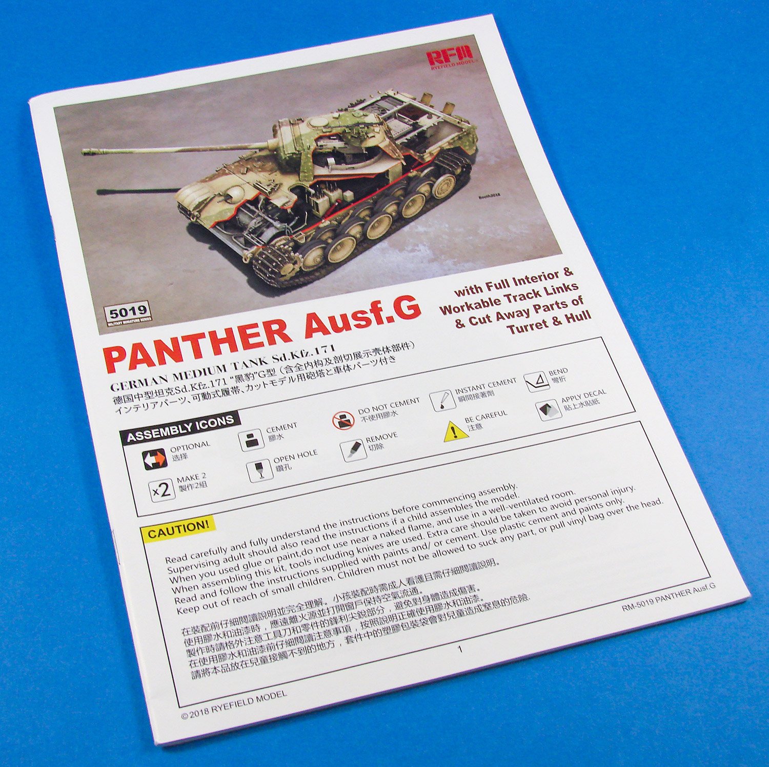
Instructions

RMF provide a hefty A4 manual for this release. Many of the constructional sequences include enough assembly to have merited further breakdown, but are still easily followed. All drawings are in line format and are clear to understand. Coloured ink is introduced to illustrate some of the finer nuances of construction, such as new part placement and where parts are only to be dry-fit at certain stages. Some of the English annotation is a little messy and could do with having been corrected, but the general gist is easy to follow. Paint references are given for Mig AMMO and Gunze paints.
Conclusion
I really do like Rye Field Models. Their presentation, execution and engineering is first rate, and they leave no detail stone unturned. These certainly aren’t models designed for a relative newcomer but are instead aimed at those with a little experience, but I also feel their price-point puts them way out in front compared with some of the legacy armour kit manufacturers that so dominated the scene for years. This is simply an amazing kit of one of the hobby’s more popular subjects and oozes buildability and presence with all of that detail within, which can now easily be built as an engineering-style model. What more can I say than you really should seek out of of these!My sincere thanks to Rye Field Model for the kit sample seen here.

-
5
-
-
For me, the RFM Panthers are nicer than the Takom, yet the Takom are still superb.
I have another RFM Panther review in the next week or so, of the cutaway kit.
-
4
-
-
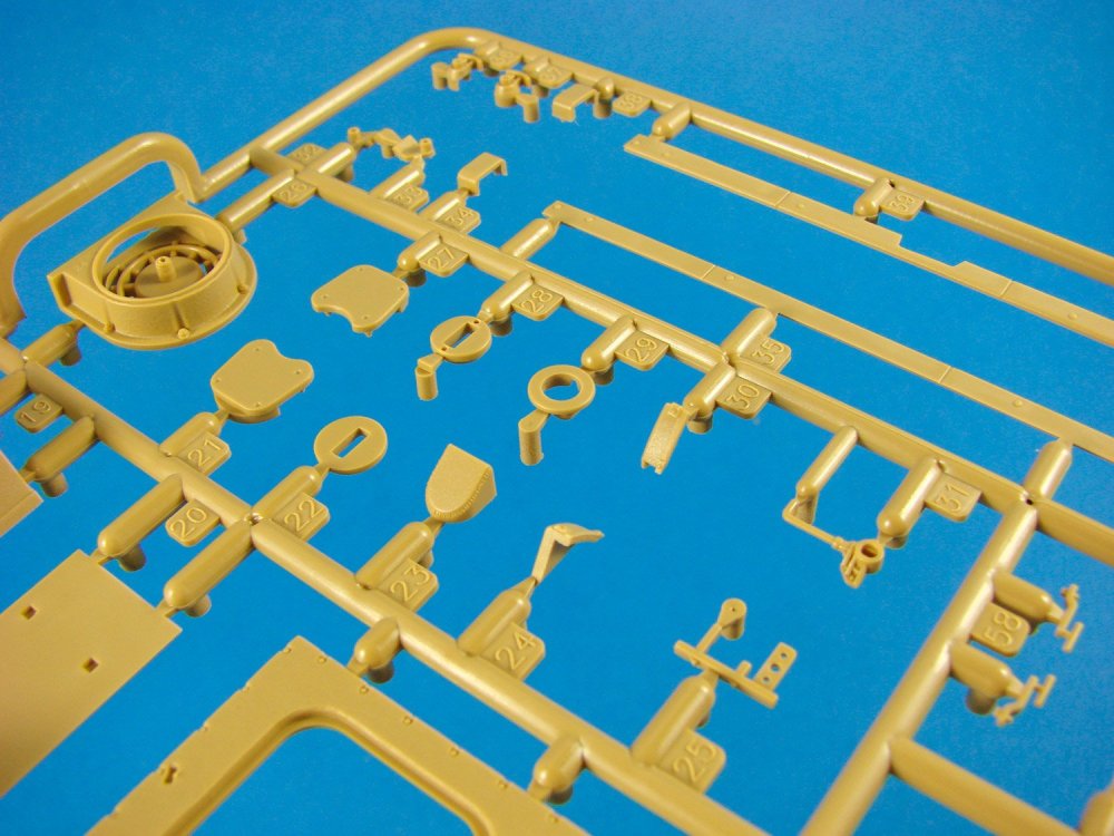
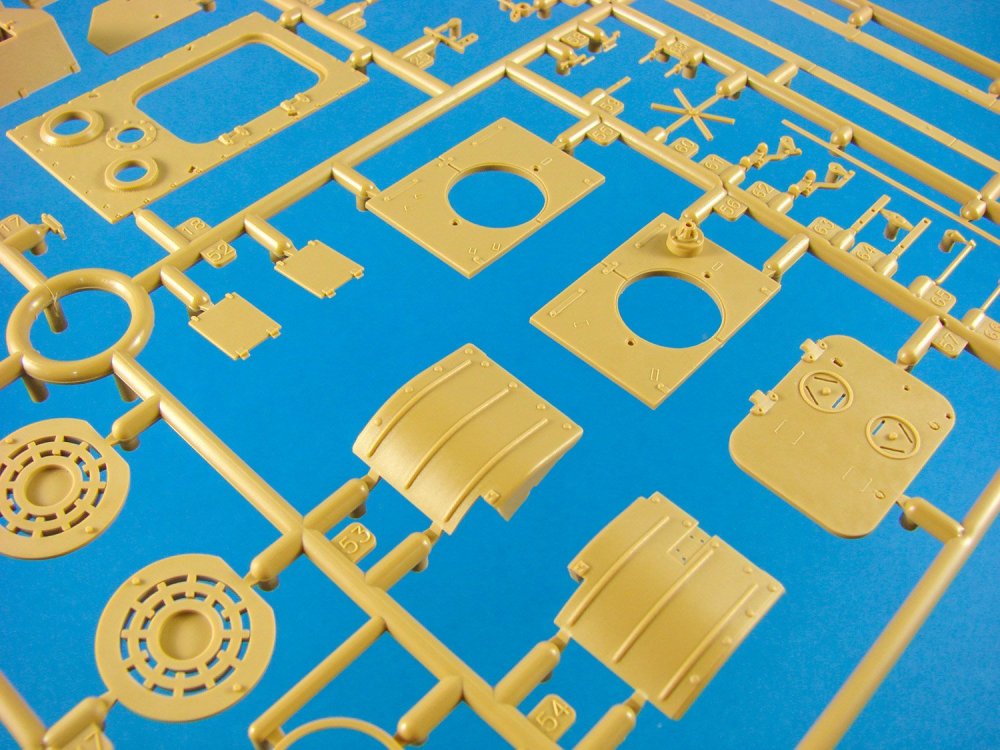
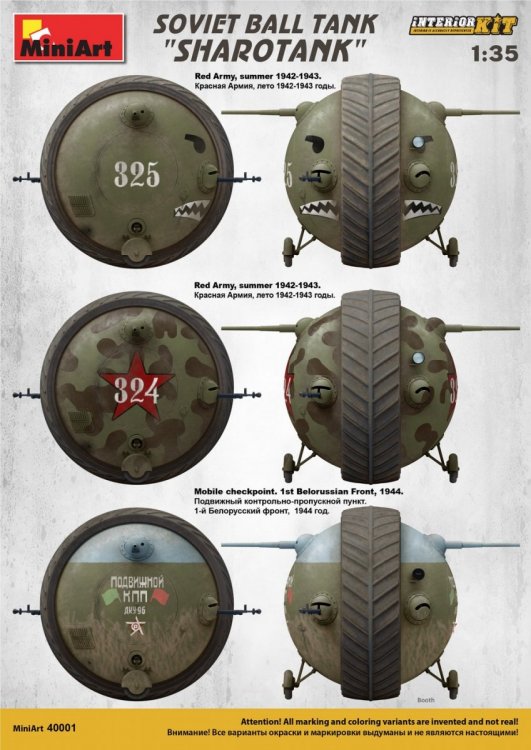
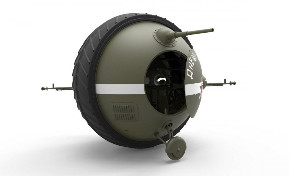
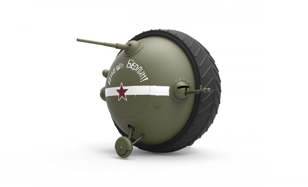
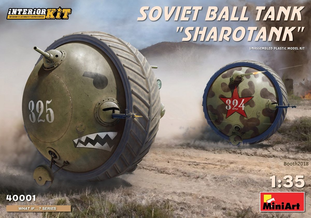
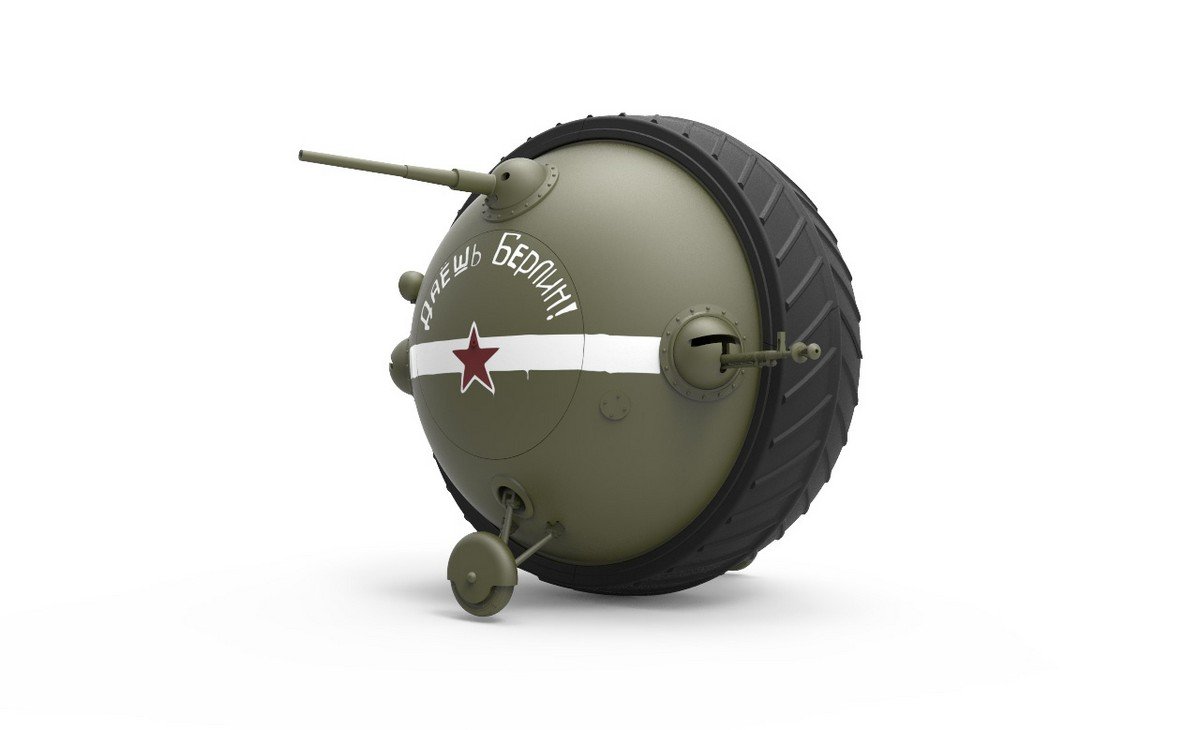
1:35 Soviet Ball Tank ‘Sharotank’
MiniArt
Catalogue # 40001

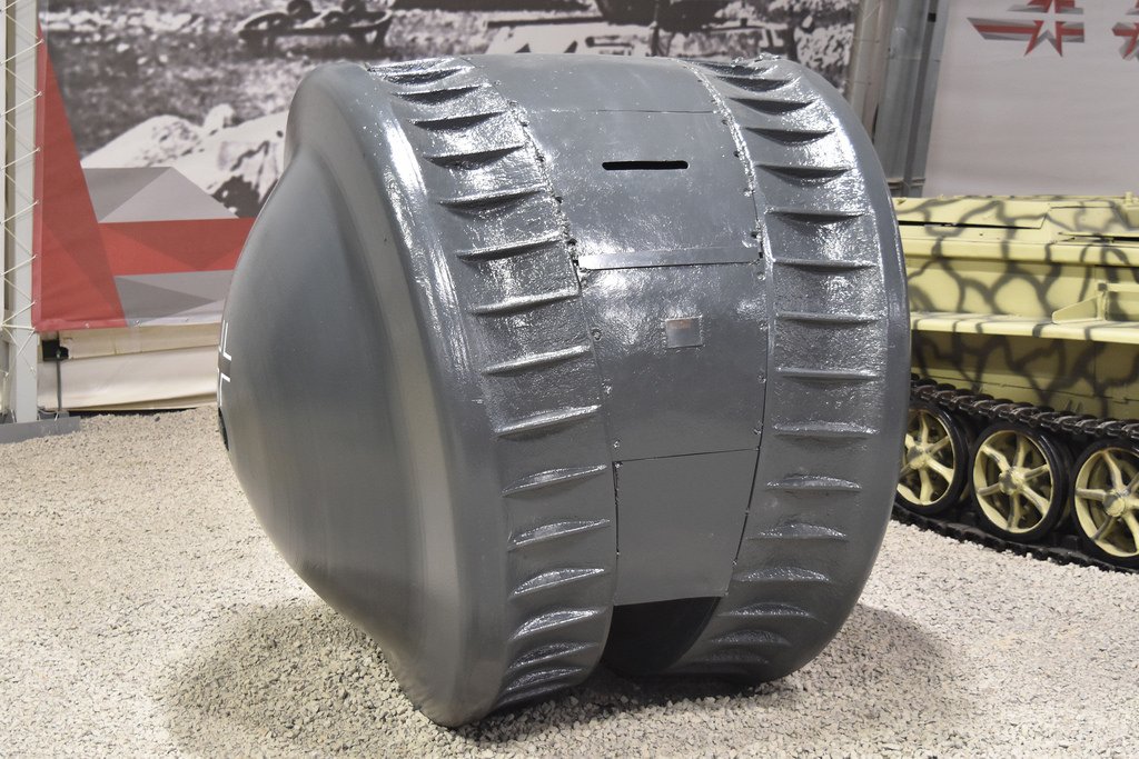
I have to say that I usually steer well clear from What-If subjects, almost to the point of purposeful avoidance. There are times though that I do get tempted, and then overcome the temptation. In this instance, MiniArt’s new Sharotank is one subject that I just hadto take a closer look at. Of course, this armoured ball tank never existed, but I’m pretty sure that there was more than an ounce of influence and inspiration taken from Item No.37 at the Kubinka Tank Museum, just to the west of Moscow, Russia. Here, a rather curious exhibit, called a Kugelpanzer, is painted in what I assume is a totally unauthentic glossy grey paint. As far as I know, there are no photos of the inside of this curiosity, and even now, it seems sort of shrouded in secrecy/mystery. The Kugelpanzer isn’t a ball tank, but it is fairly close, being a squat drum shape, with two tracks running around its circumference, and with a rear stabiliser to support it. In the front is a vision slit and a welded port with what appears to have originally had a gun protruding from it. The tracks look almost welded into position, so I don’t know if this was a mock-up, or a later-welded machine. Either way, it’s intriguing.

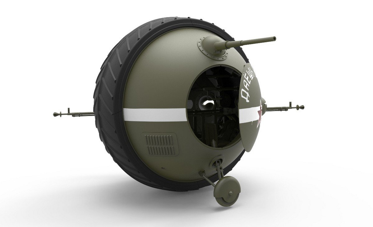
I don’t suppose it’s inconceivable that there could have been such a weapon eventually enter production, that was similar and entirely viable. It also appears that MiniArt have had that same idea with their Soviet version of the Kugelpanzer, except this one is entirely spherical and has two side stabilisers instead of a single rear one. Quite how that would actually work is beyond me! It also has a single track running around its circumference, leaving little in the way of front-back transverse stability. But hey….this is a What-If, right, so let’s enjoy the moment!
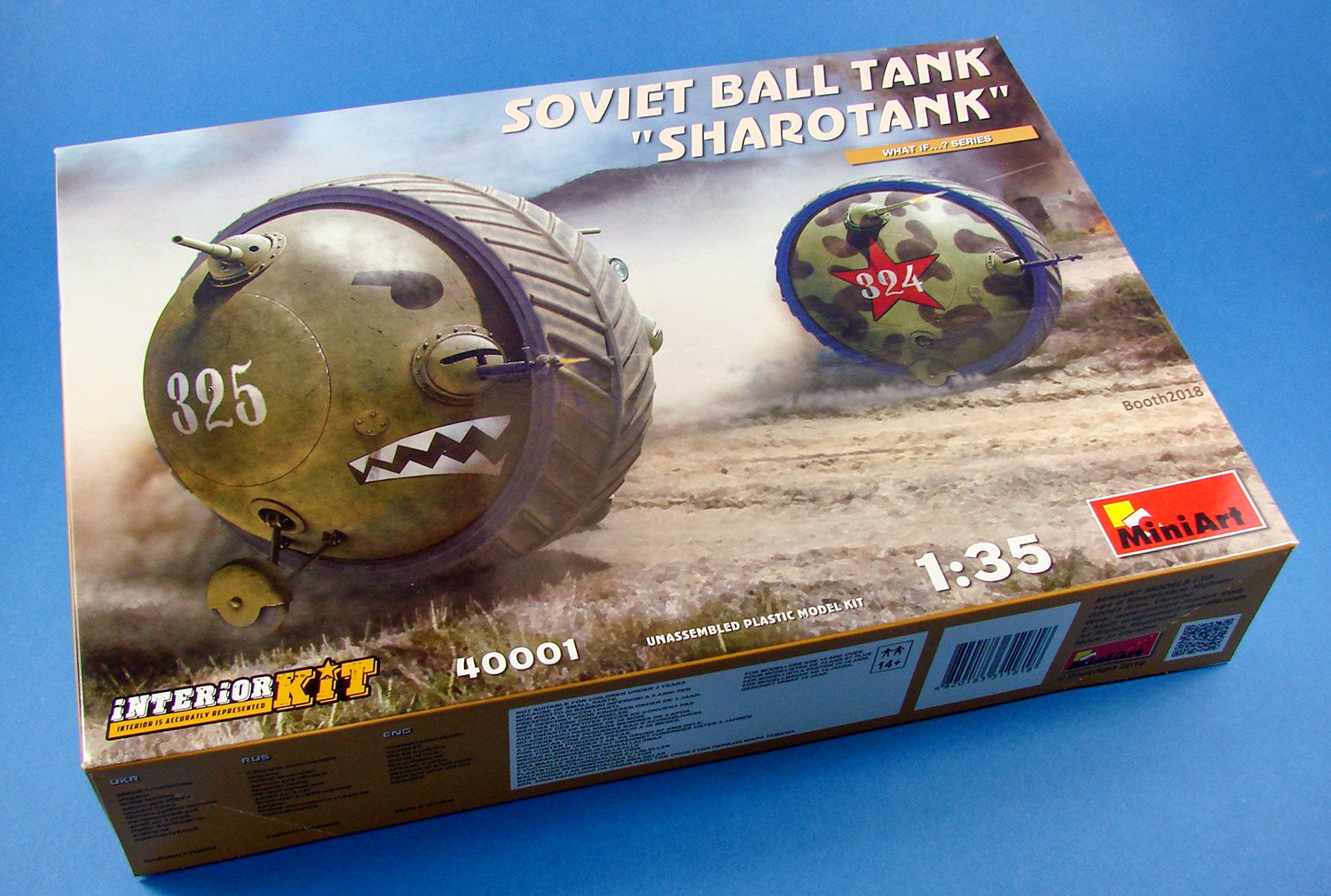
The kit

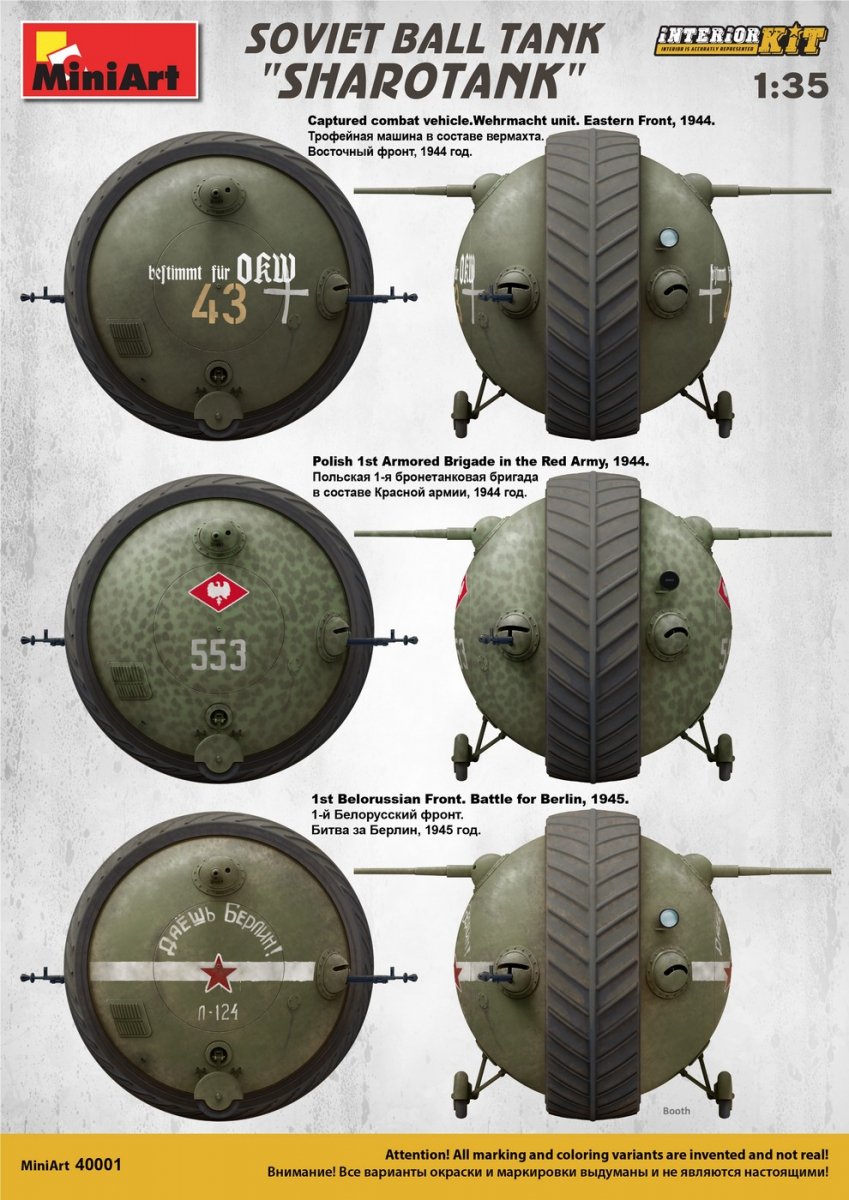
I have to say that the artwork on Sharotank really is quite nice, with two machines depicted in different schemes, kicking up dust behind them as they race on towards their targets. As can also be seen on the lid, this is the first in MiniArt’s new ‘What If Series’, and is also an ‘Interior Kit’, meaning that yes, it has a full interior! Now we can get down and dirty with what would theoretically make these curios actually tick. The box sides contain profiles for the SIX schemes that can be modelled.
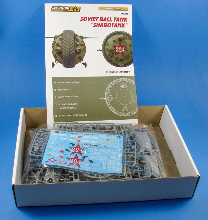
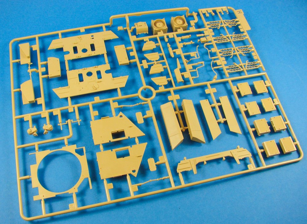
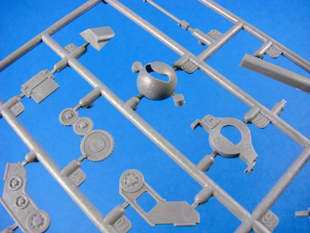
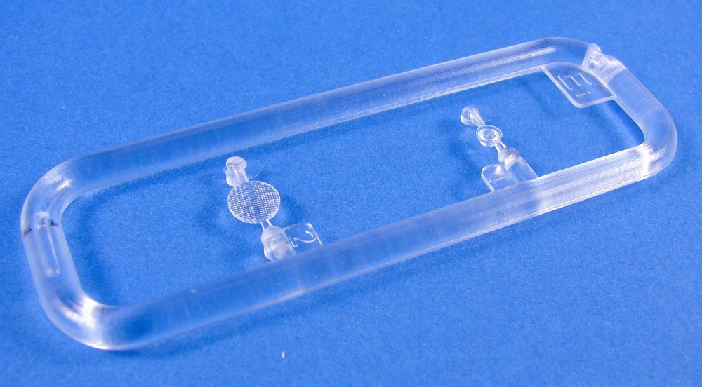
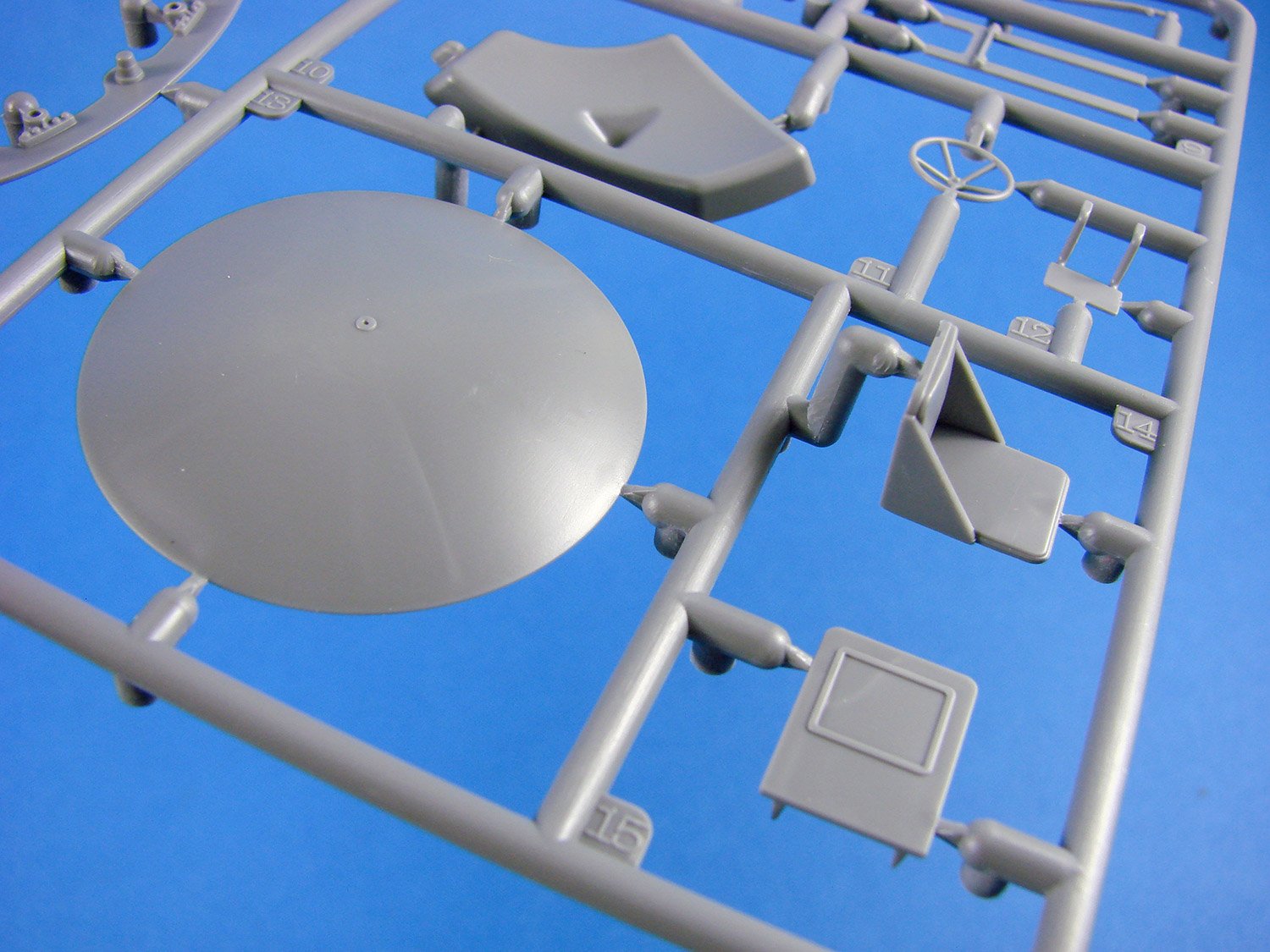
Inside the box, all TWENTY-FOUR sprues are packed into a single, clear sleeve. All except one of these are moulded in light grey styrene, with the single clear sprue being wrapped individually. Despite the high sprue count, some of these are quite small. There are only two parts on the clear sprue, and again, these are small. A nicely illustrated instruction manual and a single decal sheet complete the ensemble.

I think it would be easiest to explain the Sharotank from the inside-out, and for you to relate the photos of the sprues to those details, as this is of course a fictitious machine. It’ll also give the opportunity to know a few basics about the design, plus the opportunity to look at the possibilities that it offers n terms on display and diorama work.


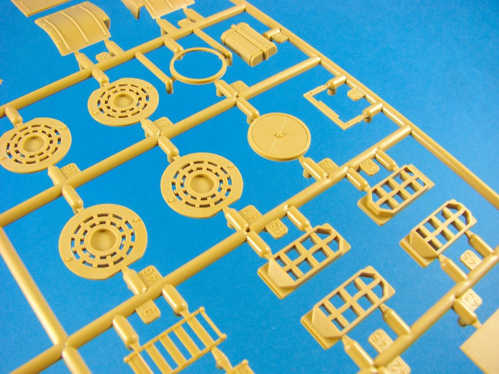
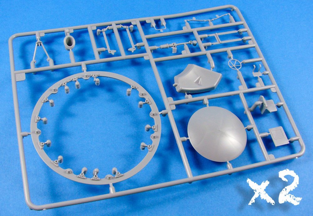
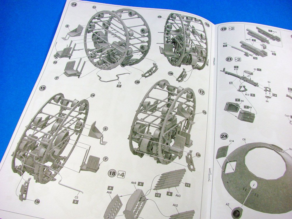
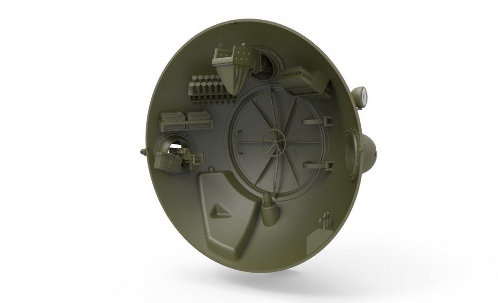
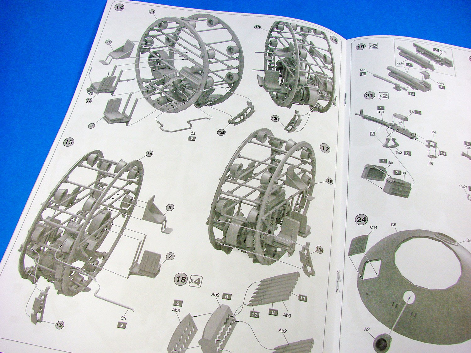
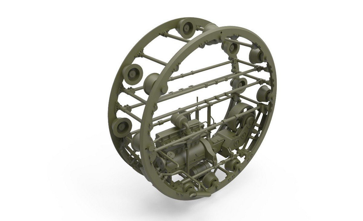
The Sharotank is based around two large, circular disc frames onto which are fastened the rollers that aid the smooth movement of the single, central track. These two frames are held apart by a series of rectangular frames which hold the interior equipment of the machine. The tank has FIVE crew (which I thought surprising), and the guns and ammunition fit into the large side dome shells. Of course, those guns (two main guns and two machine guns) can be moved either in the ball mantlets or shields into which they are fitted into. There are no forward-firing main weapons, meaning the tank driver will need some good communication with both gun operators, and it’s to be hoped they both don’t want the driver to manoeuvre for them at the same time! Access to the tank is via a large circular door in each metal domed side. These are locked by means of valve-style handle that pushes out a series of locking arms into the circumference of the door opening, rather like how the door of a large vault would operate.

Construction begins with the detailed engine, and this really does look very good, and again would lead this model to be an ideal diorama subject, and at least on display with the large doors open. The engine is connected to a gearbox what operates a roller that comes into contact with the inside of the single track. Just below the engine is what I believe to be an oil tank. This is quite small, so I’m thinking that two tank-like shapes in the inner domes are probably the fuel tanks. Just imagine dropping your lit cigarette into the rolling track area of this thing, and then sending it spinning around the interior with your crew cussing you J

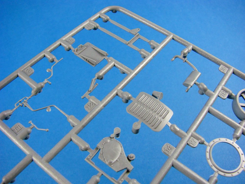

There are no crew positions within the main framework of the Sharotank, but instead, these are supported external to the frame, in various elevations and locations, so suit the crew role. The crew positions are rather spaced out in the tank layout, with no side-by-side positions. As for the guns, MiniArt has realised that both main gun and machine gun operators would indeed need bags to catch their spent cartridges, or else they would be spinning around in the interior! Gun detail is excellent, as is that of the spent shell bags. A box feeds each MG, whilst racks built into the side domes, contain the main shells. Those domes also are home to the engine radiators etc.


The guns themselves can be positioned, but the doors appear to be an either/or option for open and closed. I don’t think it would take much ingenuity to make those also open and close to suit.


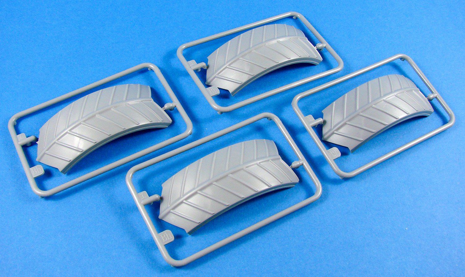
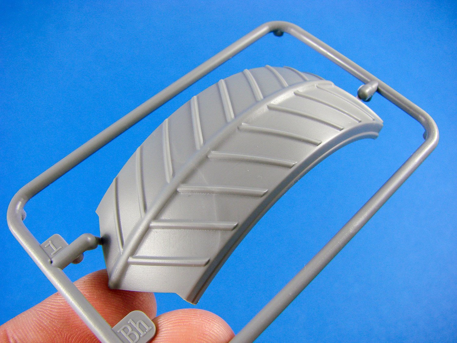
The main track is moulded in four sections , and look very good, and certainly suitable for a vehicle from Russian terrain. How they would work in the Berlin streets is another matter.
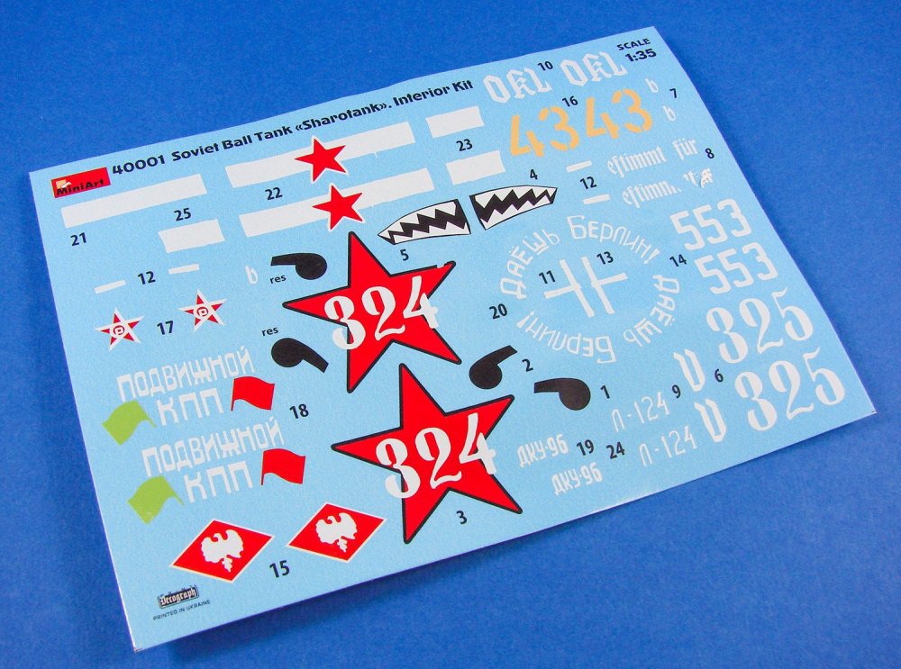
A single decal sheet is included, printed by Decograph, in the Ukraine. Printing is excellent with nice thin ink layers and perfect registration. Colour is also sold and carrier film minimal. My only gripe is that the sheet was in the same bag as the parts and is a little dented in places, with one decal being damaged. The six fictitious schemes available are shown in these images.

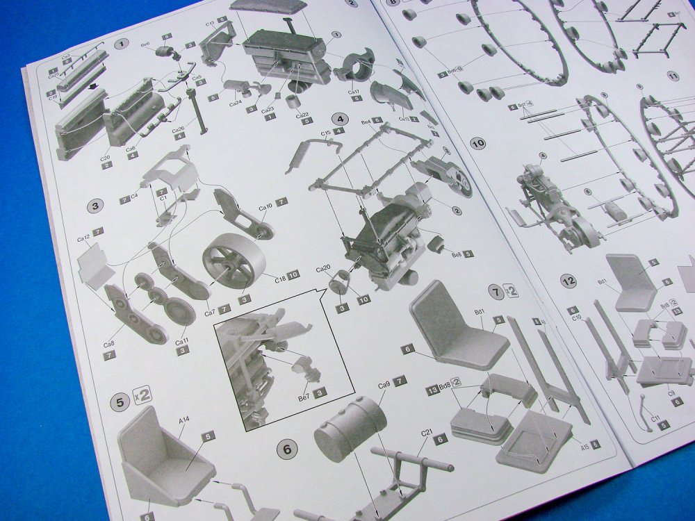
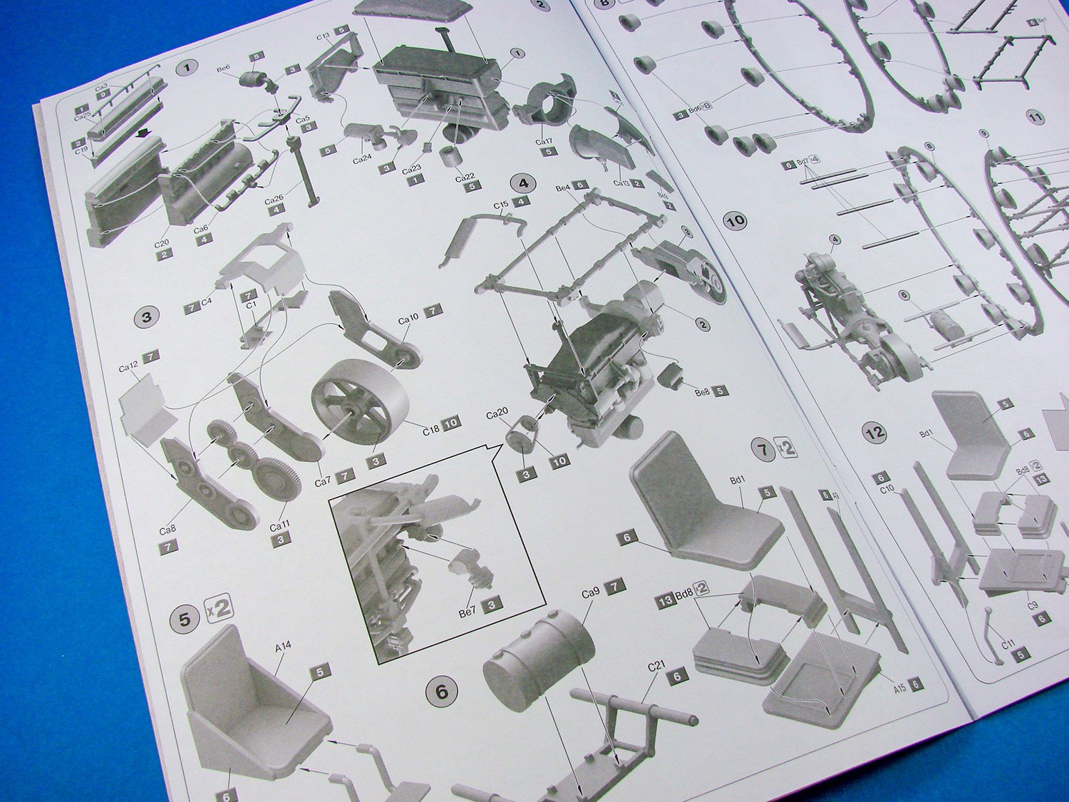
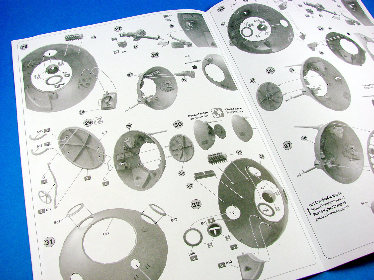
I quite like the instructions manual for this kit, with the first inner page showing three schemes, and the last page showing the same. Construction is broken down into 40 stages, using shaded CAD images for illustration, and paint references given throughout. Paint codes are supplied for Vallejo, Mr. Color, Life Color, Tamiya, Testors, AK Real Color, Humbrol, Revell and Mission Models brands, as well as standard names.

Conclusion
It really does take something quite extraordinary to make me look twice, when it comes to What-Ifmodels, but this is most definitely one that appeals to me. MiniArt has taken the ball-tank concept and produced something that is reasonably credible, and with the complete interior, would give that extra buildability factor. Moulding and execution is first rate, and only minor parts clean-up is required. The finished result is also fairly small, so no issues with display space here! A lovely little model which will doubtless provide many fun hours in the workshop.
My sincere thanks to MiniArt for the review sample seen here.
-
I built this as a kid, so it's memory lane for me!
-
2
-
-
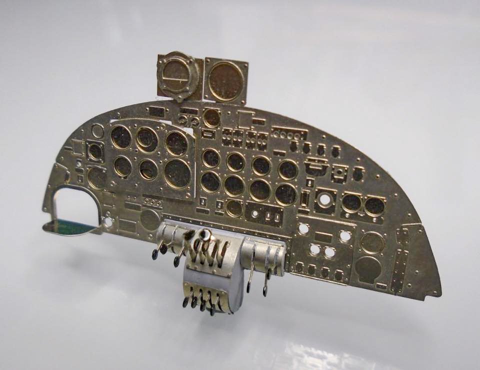
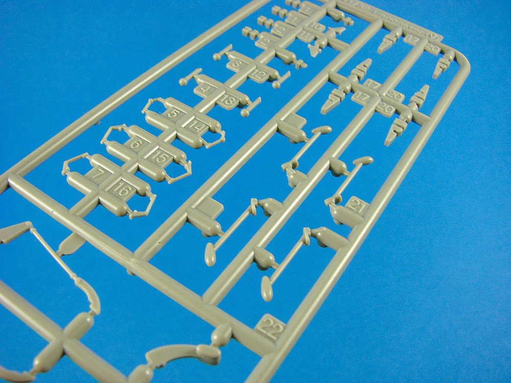
This build is becoming more of just a collection of random photos as I progress through major construction. Again, I want to do ad much of this as I can before I hit paint. I've also decided to showcase the forthcoming Airscale cockpit set for this, which should be with me tomorrow, and decals to follow in over a week's time. I'm sure you'll agree that the effort in removing the moulded detail is definitely worth it, and is already done in readiness. Here are some photos of Airscale's prototype set:
I'm still waiting on some replacement parts coming from HKM for various improvements and short shots in the test sprues, and those include the hinges on the original Sprue V. Until I get that sorted, here is the state of the tail.
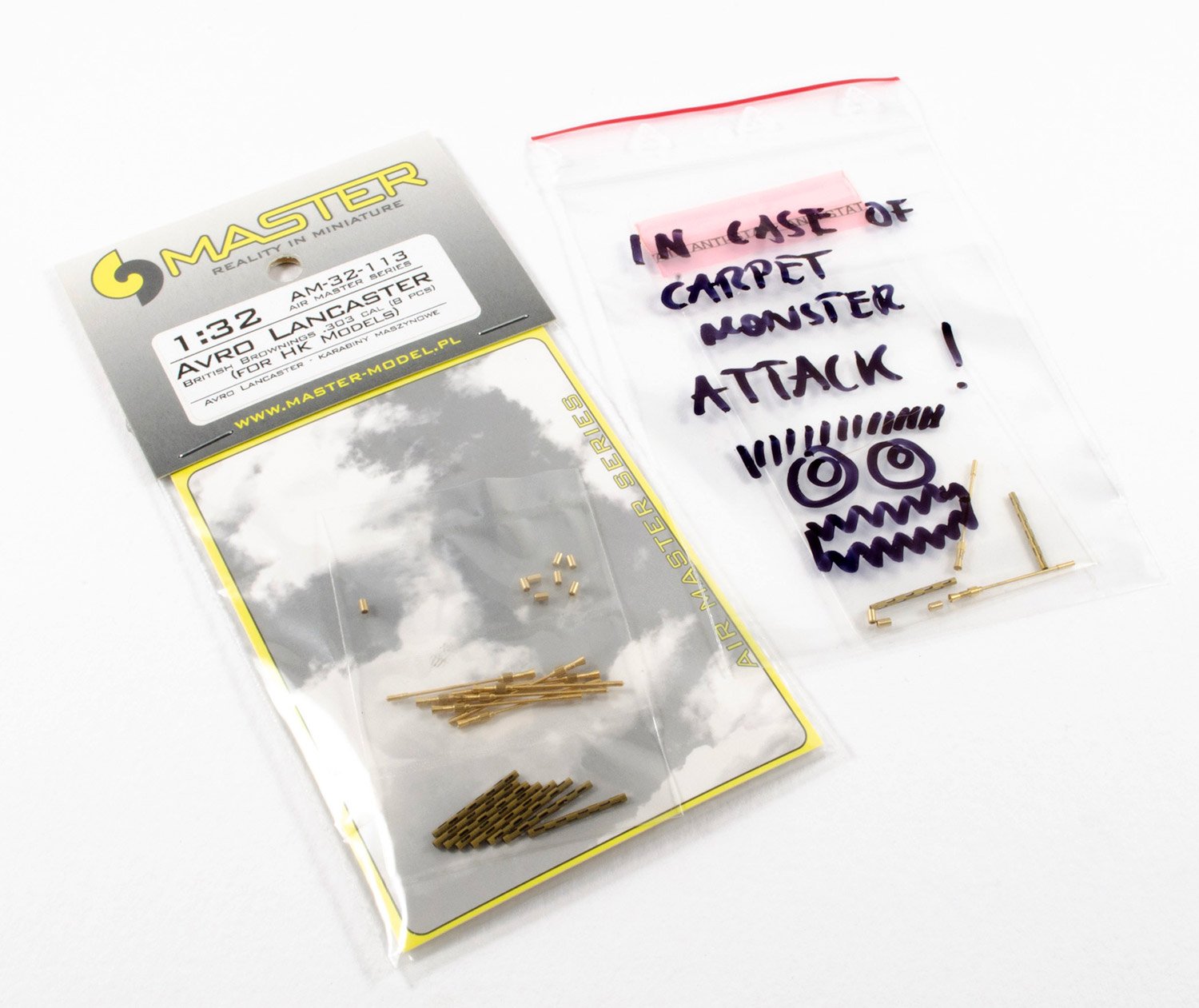
More aftermarket?
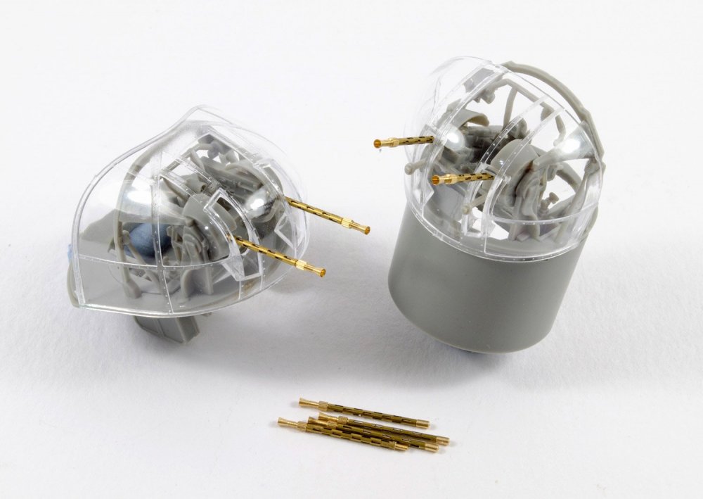
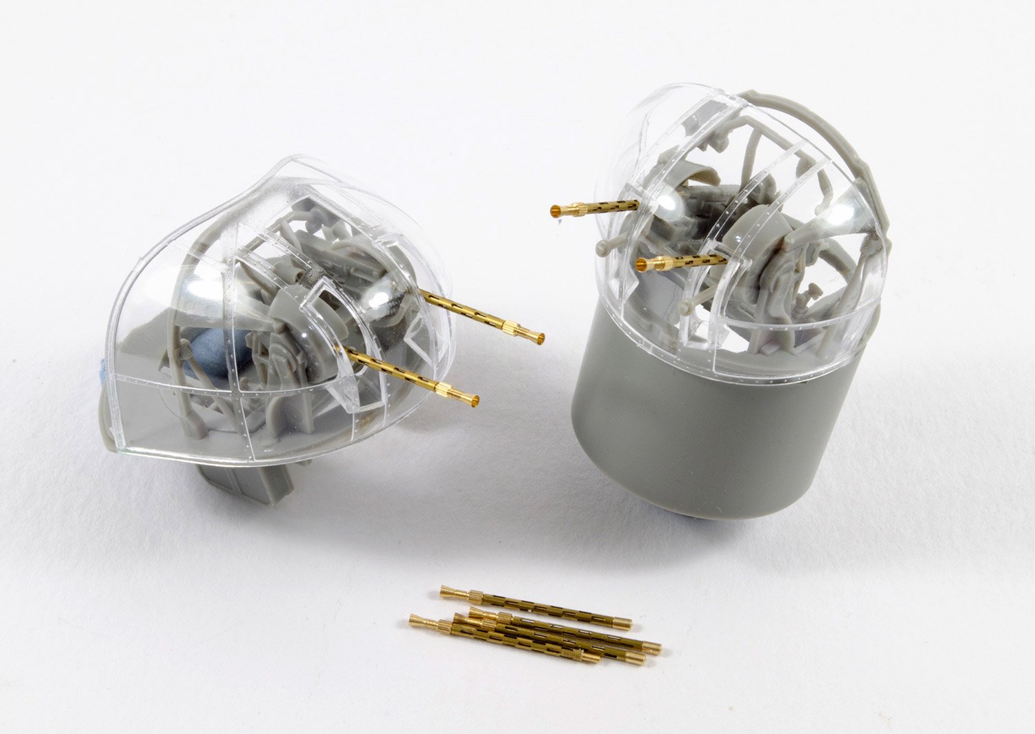
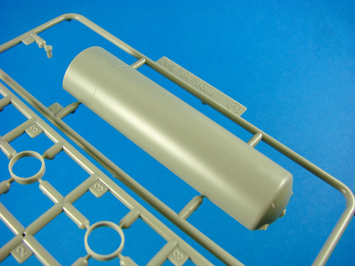
Ok, I'm using the new Master Models Lancaster barrel set. This comes with adaptors to fit the barrels to the plastic guns. They work a treat. Here are two turrets fitted out already.

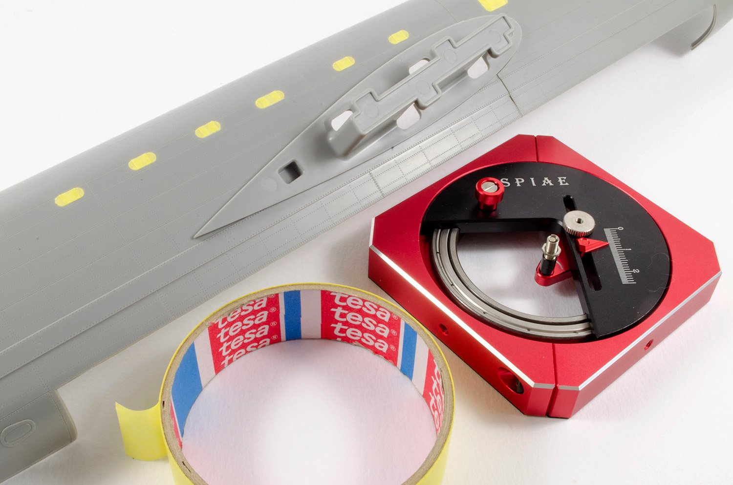
A little more preliminary work too with masking the fuselage windows, both inside and out. This is where a circle cutter comes in real handy.

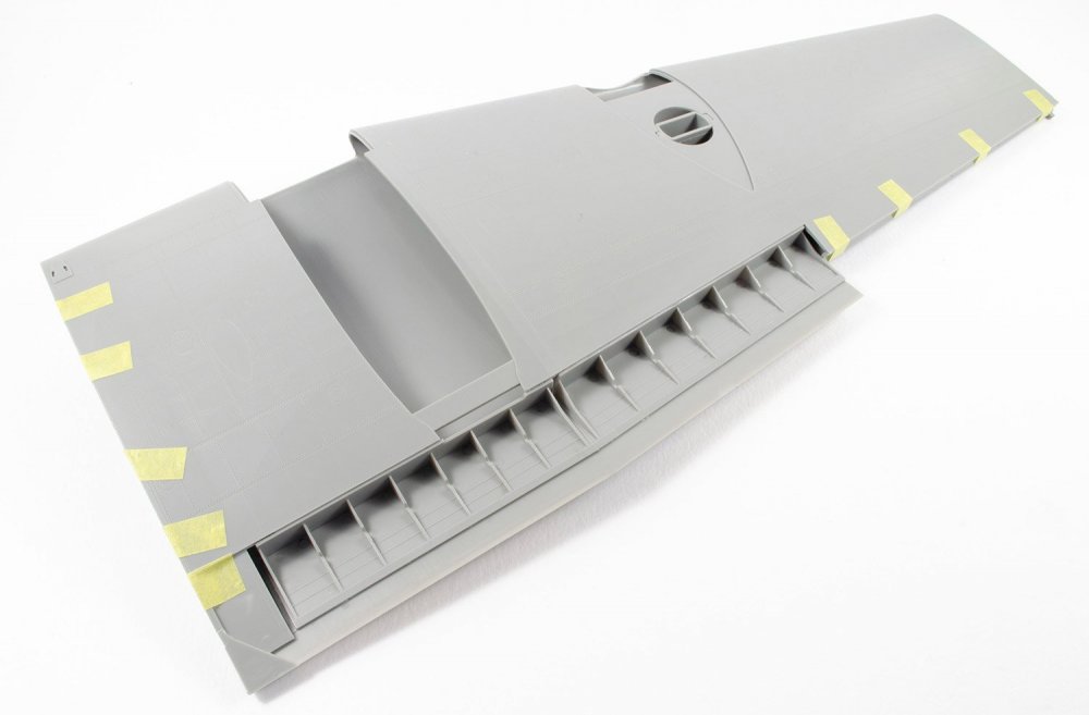
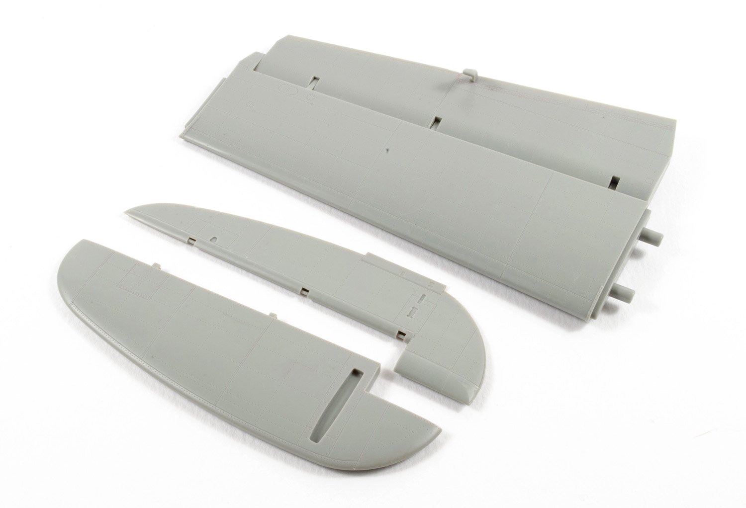
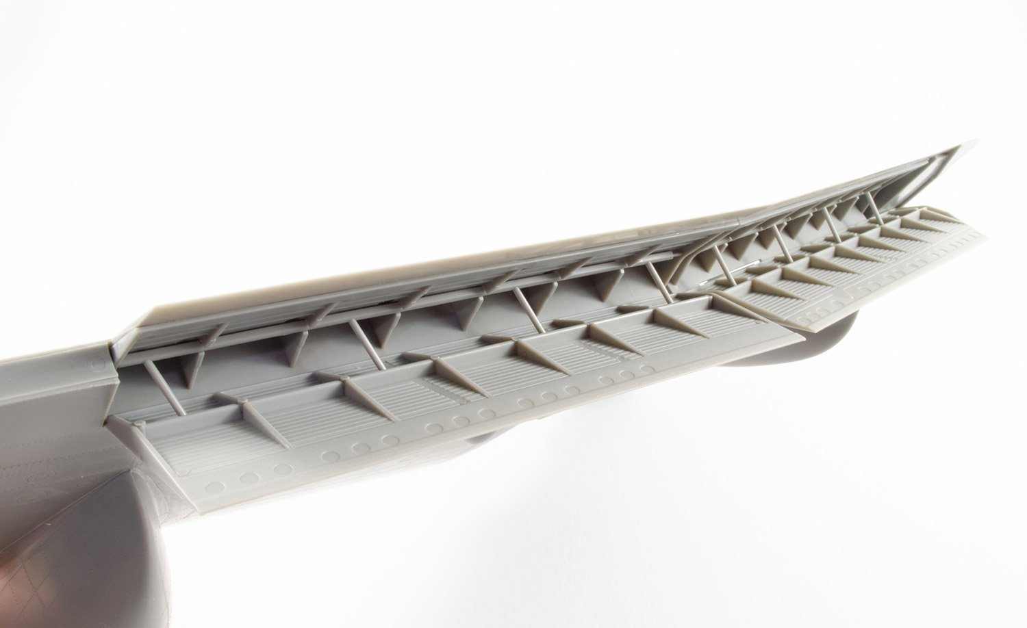
I know you guys like some flap photos, so here is a set fitted to the port wing. Again, they fit like a dream.

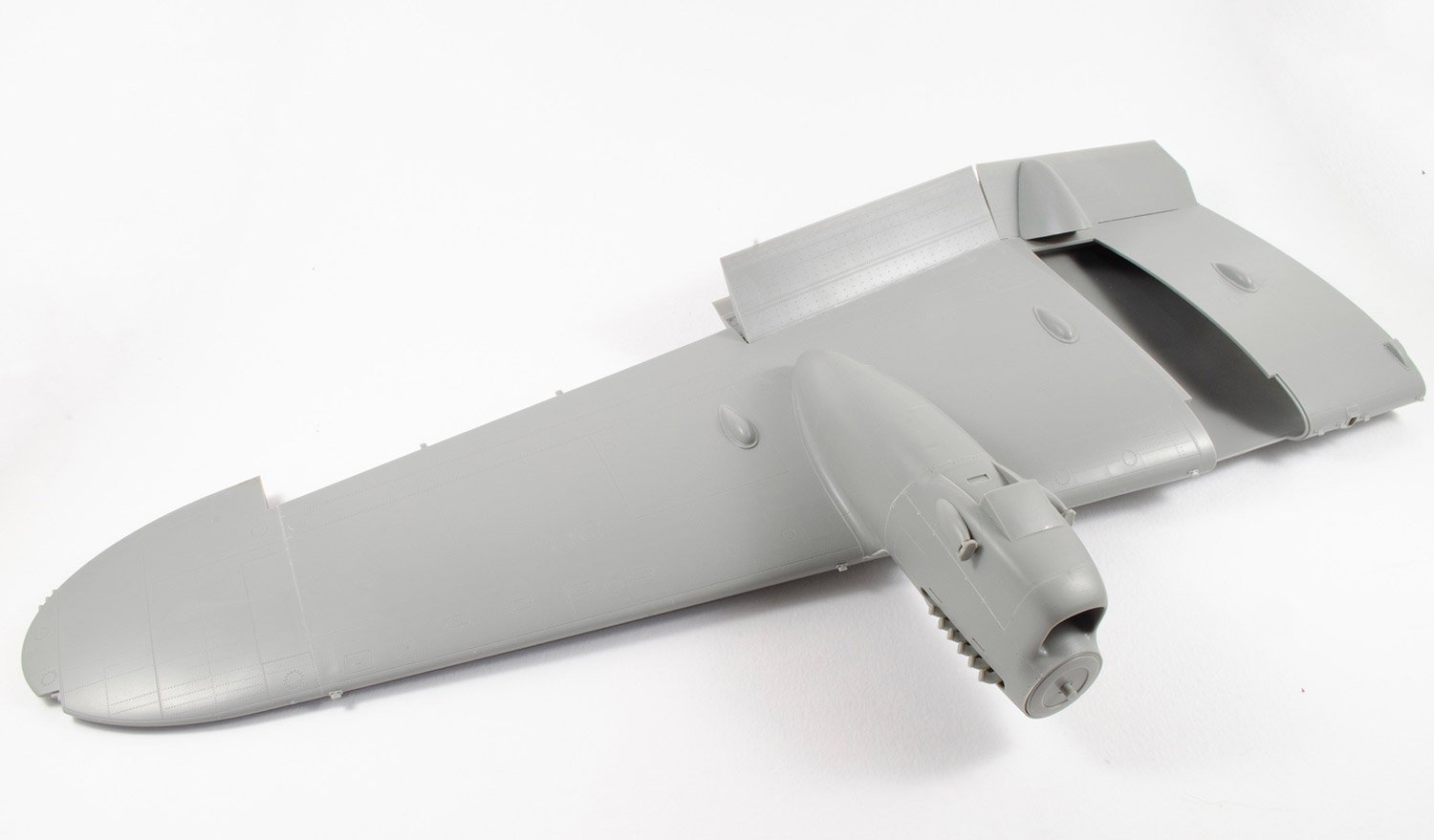
Last photo for now as I fit the outboard engine (No.1) to the wing. Zero issues with fit or fettle. A joy to assemble.
-
9
-
-
Ok, time to break regular cover.
If you read one of my magazine articles, or indeed most by anyone, you'll see a relatively linear workflow.....you know....cockpit, engines, closeup, wings, paint etc. In actuality, the workflow is less linear and designed to maximise our time at the workbench and aid deadline schedules. So I don't suppose it will surprise you all to know that I've actually built most of the model in some form, minus paint at this stage. My plan is to build as much as possible and then add wiring etc, and then crack up the airbrush.
As I'm still waiting on a few replacement parts from HKM, I thought I'd add a series of photos here to show what I've built so far. It certainly beats no updates for a while!


-
13
-
-
Hoping to have something else to show you this week. Things have been a little slow due to illness recovery and other writing.
-
5
-
-
If any of you guys will be at Telford, maybe we can meet up on the Saturday?
-
5
-
-
40 minutes ago, airscale said:
oooh not seen one of these in the flesh - looks fab James
I toyed with doing a PE cockpit & instrument decal set for this, but now the WNW one is on the cards I will leave it to the big boys to play in that space
")
really looking forward to seeing this come together
Peter
And as usual, Airscale will make a full appearance in this one too
")
-
3
-
-
2 hours ago, Grunhertz said:
To be honest Jim the photos look fine, the problem is every troll in the world is lining up to have a pop at this kit. I don't know why I suspect that every thing changed because of the WNW kit but it's not out and this is. So let's enjoy it
Remember, everybody is an expert
2 hours ago, HubertB said:Will follow this one with interest.
As for the comments on another forum, it is fascinating to watch mob phenomena. Since the annoucement of the WnW release in one year (or more) from now, comments about the HK kit have evolved from enthusiasm to bad-faith trashing. I suppose it is human nature to judge comparatively (and in this case, the comparison is between real stuff vs 3D renderings) rather than in absolute terms the merits of products
 .
.
Anyway, from your review pics and considering your talent, I am sure your end result will be outstanding

Hubert
Your faith in my ability is welcome! Thank you.
You are right with your comments on the phenomena. Another day at the plastic modelling criticism coalface.
 1 hour ago, Maxim said:
Interesting that the majority of those people that trash a kit before it's even released are often people that are arm chair experts and never build nothing. Both the HKM Lancaster and the WNW Lancaster appeal to different modellers. I think the WNW kit when released will give many people sticker shock. I can just hear those experts whining about the price. The HKM kit will give many modellers the chance to have a Lancaster in their collection who can not afford the WNW Lancaster. Both kits tailor to different modellers. The HKM kit is a nice accurate Lancaster out of the box. The WNW Lancaster comes with all the bells and whistles. We never had it so good.
We certainly haven't had it so good. Couldn't agree more!
I'm really enjoying this build and looking at making my own little marks where I can. The aim is to show the kit in the best light that I possibly can, as is the same with anything I try my hand at.36 minutes ago, Wingco57 said:Nice touch James. That panel covers the wiring loom to prevent damage.
Cees
Dank je!
-
5
-
-
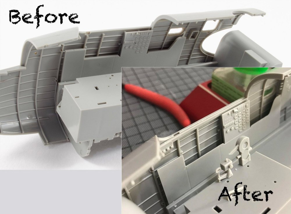
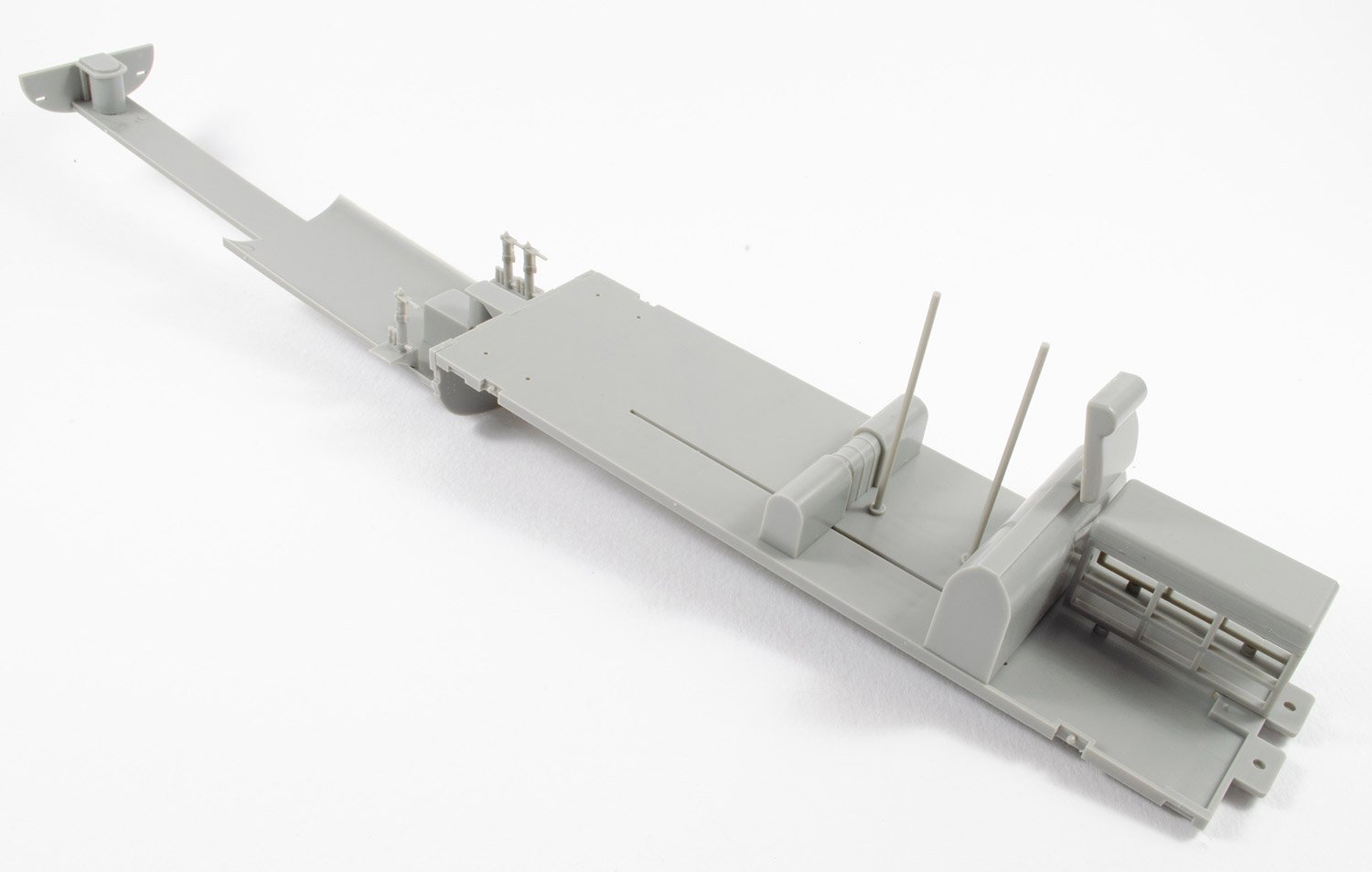
After a little studying of some photos, I decided to thin the wall panels adjacent to the engineers console, and also scribe a line under the console to separate it from the surrounding plastic panels. Here's my work:
-
10
-
-
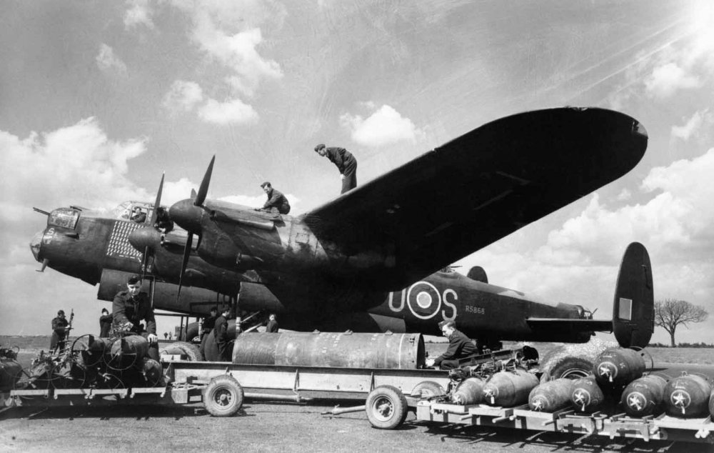
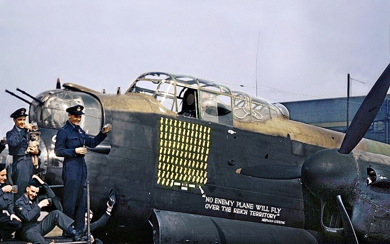
Lancaster B Mk.I, R5868, PO-S (S-Sugar)

It's been a week or so since I tool delivery of the test shot for HK's soon-to-be-released Lancaster kit, and despite some pretty crap illness last week, I made some headway this weekend and snipped some plastic. Most of what you see here is dry-fit, with a very small number of glued components. I've read on another site that this model has soft detail and soft edges. Perhaps that's the impression my photos gave, but actually having the plastic here, I know it's not the case, and is no better/worse than recent and contemporary releases, and is every bit as sharp as I would expect from a modern tooling. There was also a hint towards 'brand loyalty' too, suggesting that I would happily write nice words where none were really justified (in not as many words). My answer to that is bullshit. There's no such thing as a perfect kit, and this is far from a perfect kit. However, the Lanc is my thing, so here we go.
From the RAF Museum:
QuoteBuilt by Metropolitan-Vickers at its Mosley Road works, Manchester. After completion taken by road to A.V.Roe plant at Woodford. Part of a batch of 100 originally ordered as Manchesters in 1939 of which only the first 43 were built as such, the remaining 57, including R5868 being completed as Lancasters as part of contract No.982866, serial numbers R5768 -R5917, delivered between Mar 41 and Aug 42.

Building a Lanc
As I have said, work at the moment has simply to snip some plastic and do a little test fitting. This time it's quite nice to be furnished with some instructions as I was building blind with the test shot fuse I received in Shizuoka. Unlike that test, this one required me snipping off all of the injection points which double as pin towers, from the circumference of the fuse halves. These are connected to the joint faces, which I prefer, and you'll notice that because of this, there are no pin marks within the fuse halves. Of course, the nose is a separate unit too.
Hers's a couple of basic mock-ups of the cockpit area, minus many key details which still need to be installed. This kit does have a serious lack of wiring moulded into the cockpit areas, linking up the various avionics panels. This will need to be added with some lead wire before I can start to add some paint. When complete, things should look quite different.

The bomb bay is around 12 inches long and is constructed as two parts. No other items fit into here apart from the sidewalls. The munitions plug directly into these plates. 18 bombs and 1 cookie.
I also did a little turret work too, and here you can see the rear turret sat in position on the rear fuse. Note the tail spar boxing and the walkway. There will also be internal fuselage doors installed here, which I'll add when the interior is painted.
More soon!
-
9
-
-
-
36 minutes ago, Bomber_County said:
Thanks James for very in depth review, as Ernie said a HKM followed by a WnW would be fair.......
That's the plan, but it'll be a year until the release, so I doubt I can do that until then.
-
3
-
-
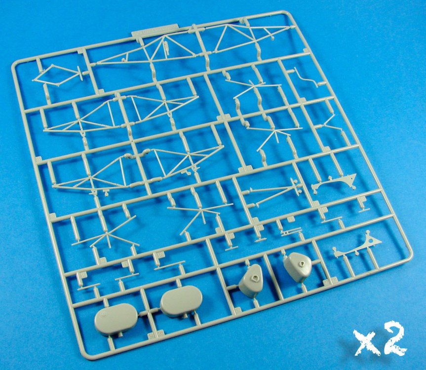
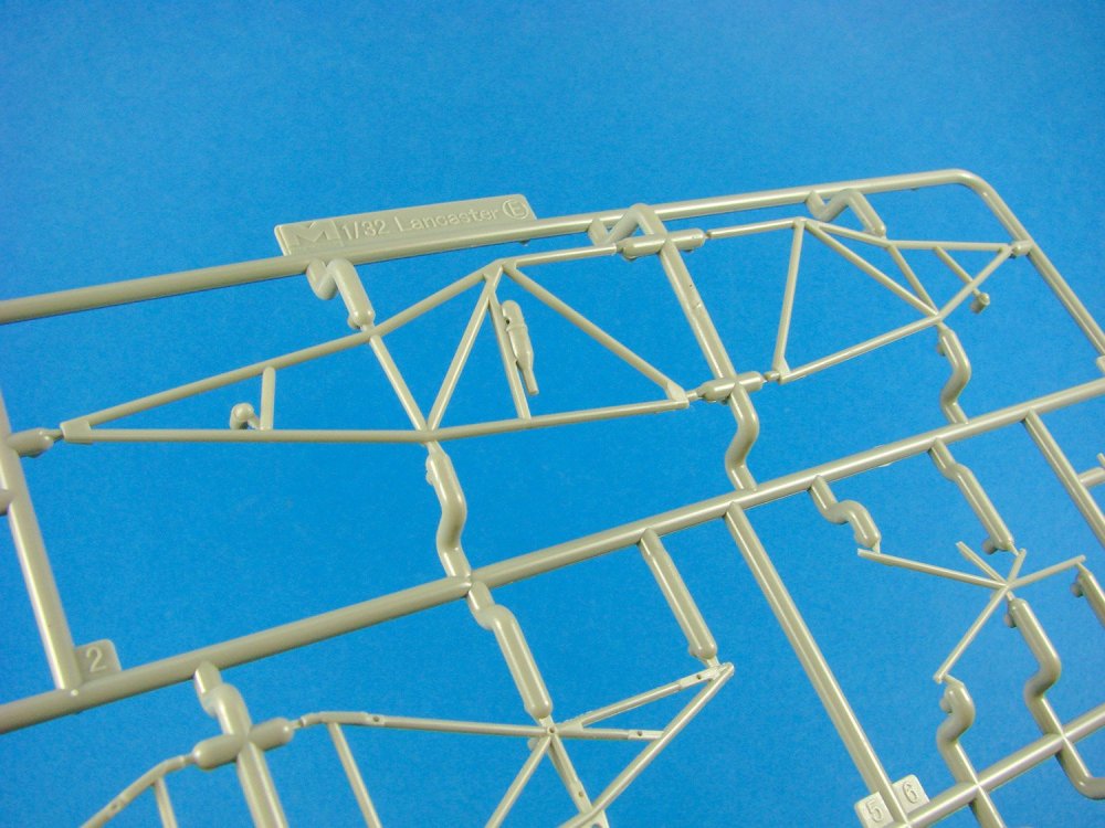
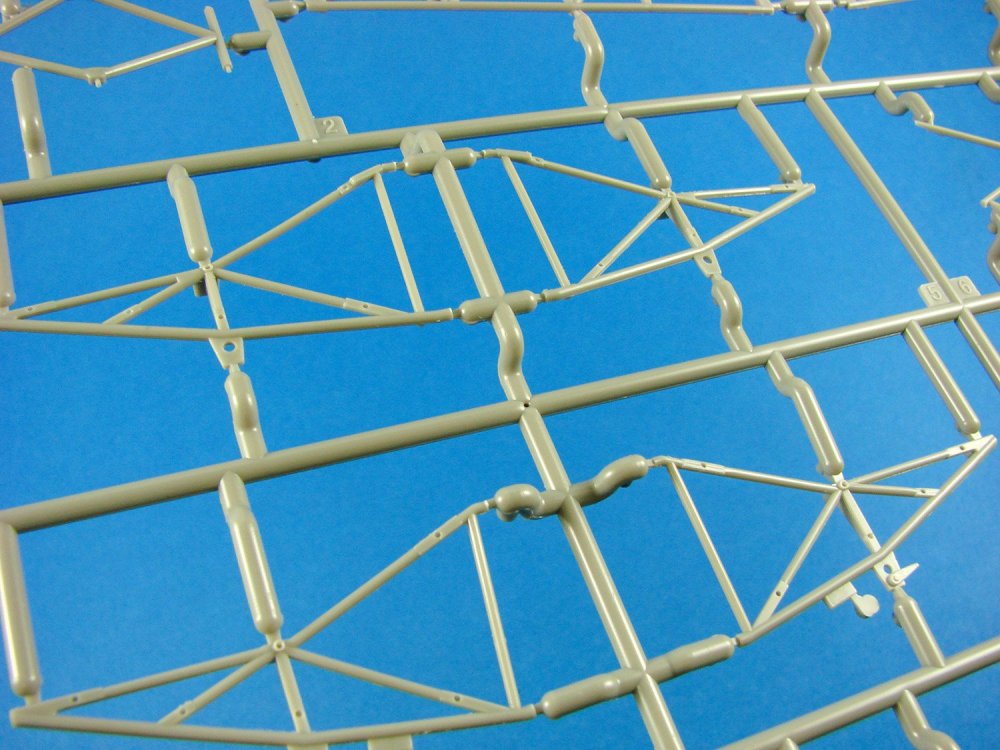
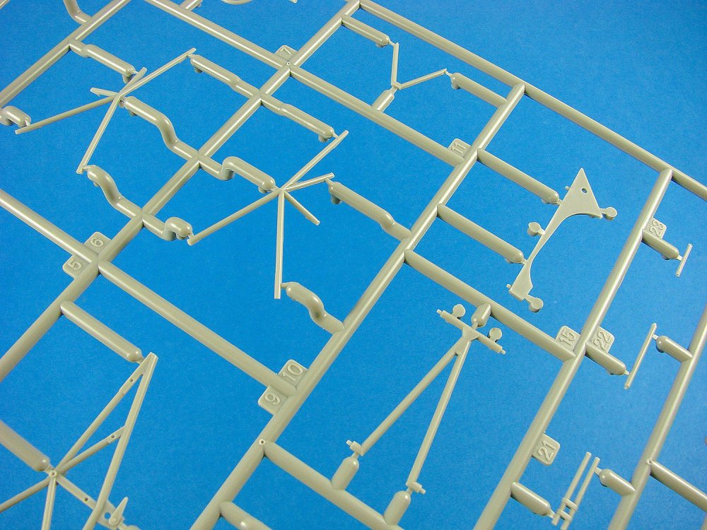
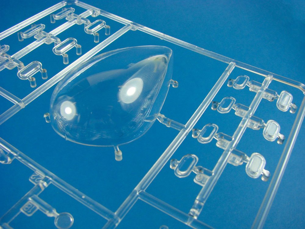
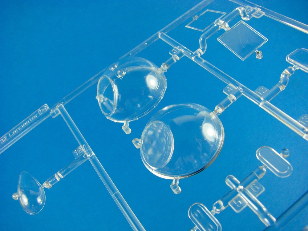
1:32 Avro Lancaster B Mk.I
Hong Kong Models
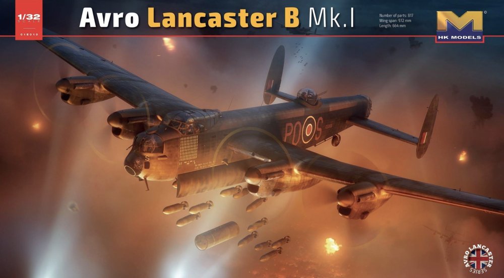
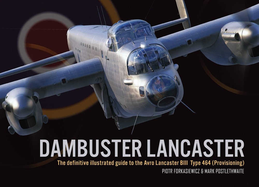
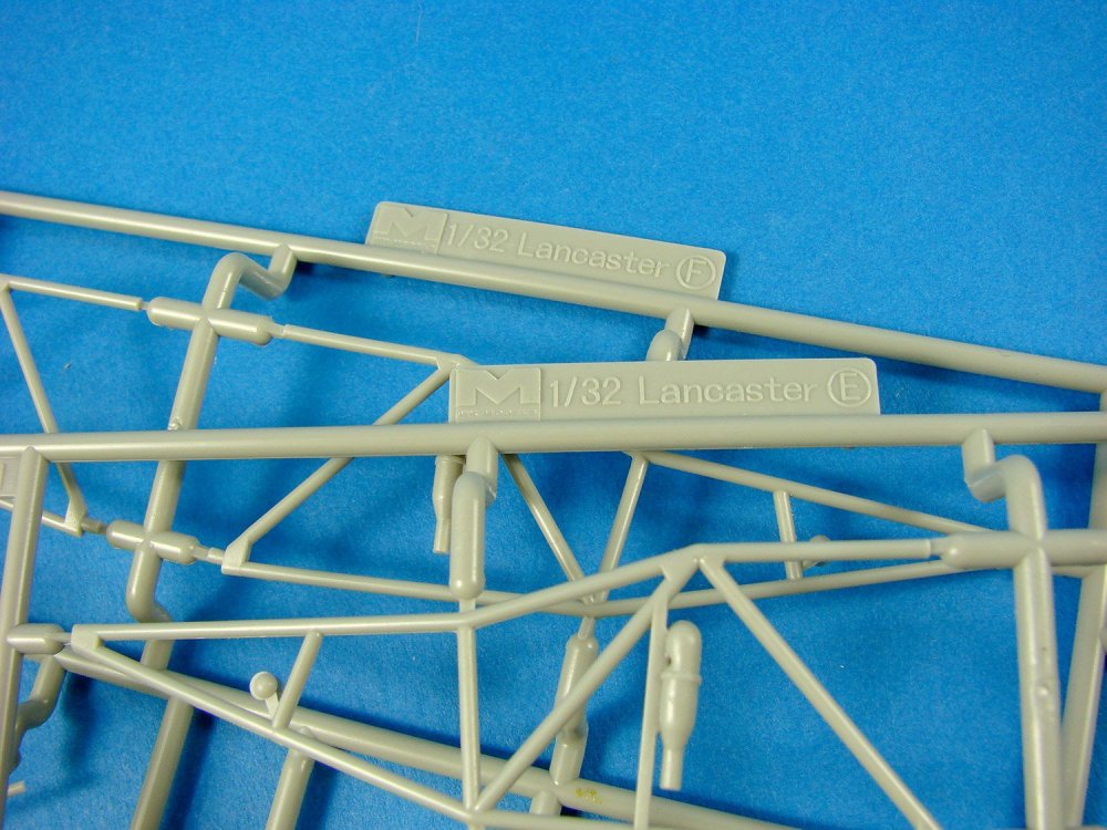
Well, it’s almost here. After a few short (some would say long!) years of delay, the gargantuan Hong Kong Models’ 1/32 Avro Lancaster B Mk.I is soon to hit the shops, and is in final production as I write this. In a few weeks, the decals will be printed, as will the instruction manual and glossy box with its artwork by Piotr Forkasiewicz. There’s no doubt that this will be an impressive product, and certainly one that will make many a heavy-bomber fan very pleased indeed. HK’s kit has 817 parts, a wingspan of 972mm and a length of 664mm, so you will need some decent place to display it when completed. The wings have been designed to detach in the same way as the B-17, with a slide and lock mechanism, and looking at the instructions, and parts, it does look like you may be able to also detach the substantial tail and fin assemblies. The final model will also come with three schemes, one of which is S-Sugar (PO-S) which adorns the box art. Stencil decals will also be supplied.

 \
\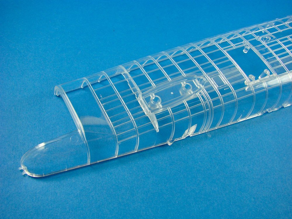


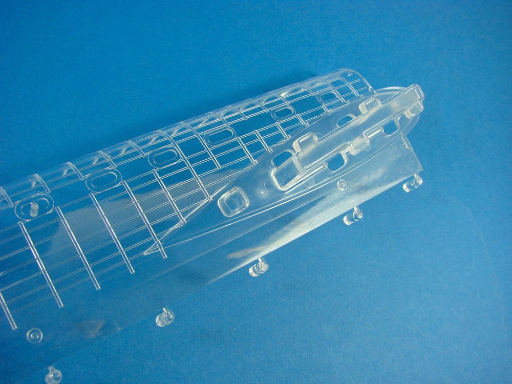
My test sample is by no means the final version. A small number of other modifications have already been applied since mine was pulled from the tooling, including an improved wing-locking system via tweaking the wing tools. Arriving by DHL Express from HK, the kit you see here arrived in a plain card box with all parts bound in a many layers of bubble-wrap. However, the clear fuselage/nose parts were actually ready in their heat-sealed packets, and these will be included in the Limited-Edition release. At this point, I expect that the standard grey parts will also be included with this Limited-Edition. The clear parts are also covered in a peelable protective film to lessen the chance of any scuffing on that crystal clear and shiny surface. A relatively small quantity of Limited-Edition kits will be released, and I imagine that a fair few of these will have been sold on kit pre-order.


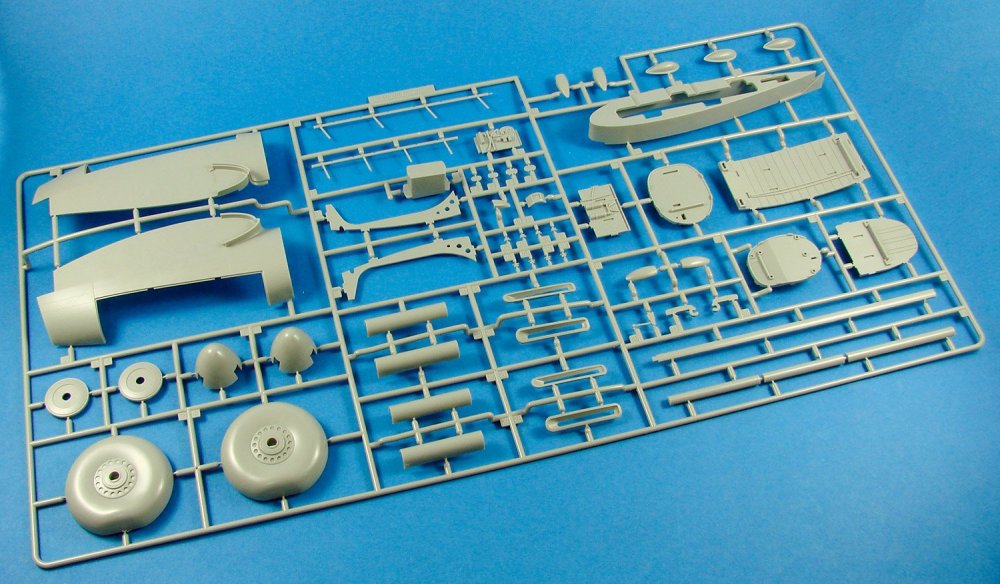
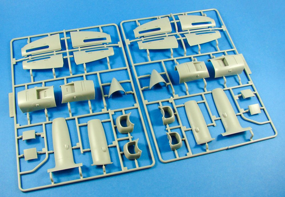
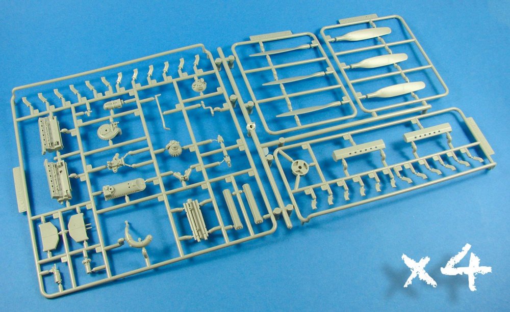
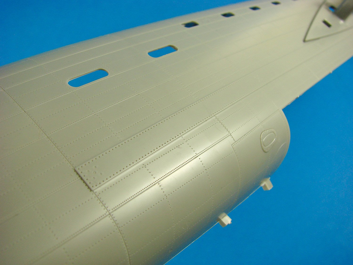
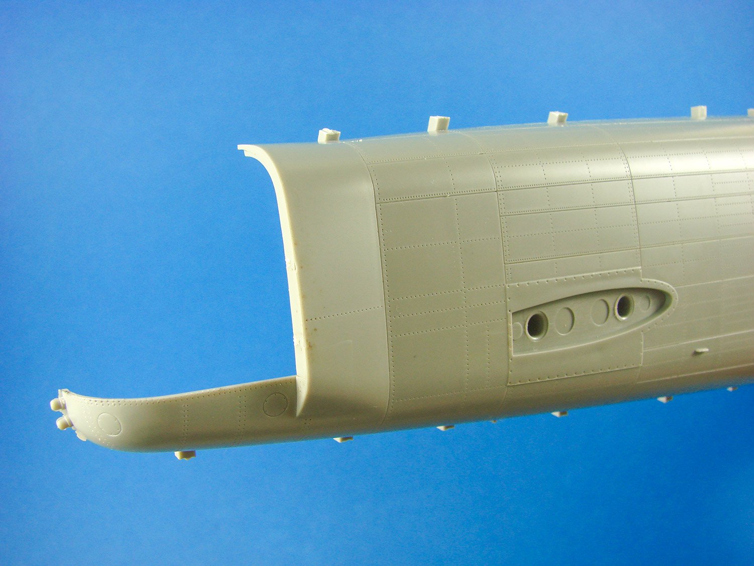
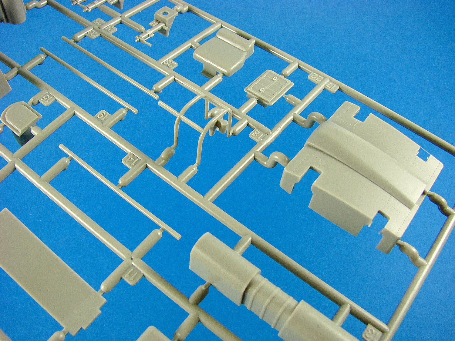
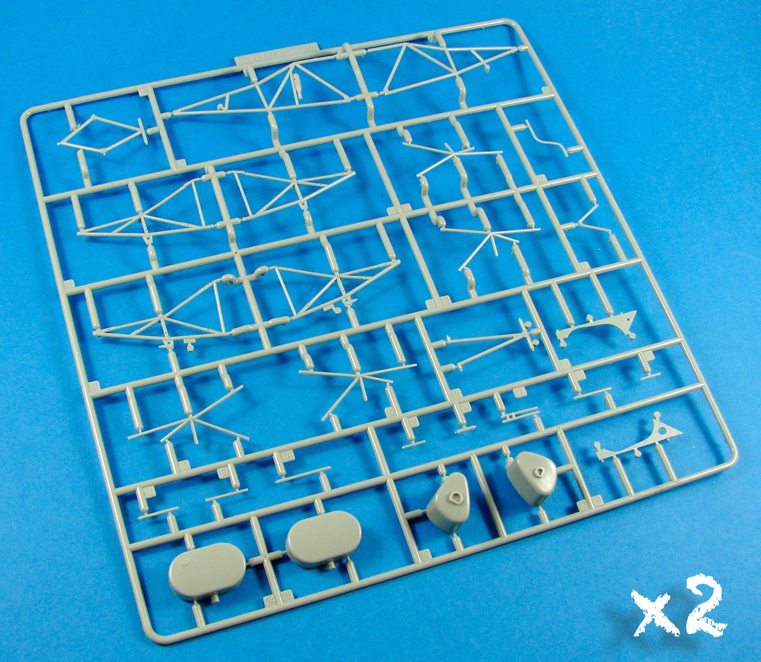
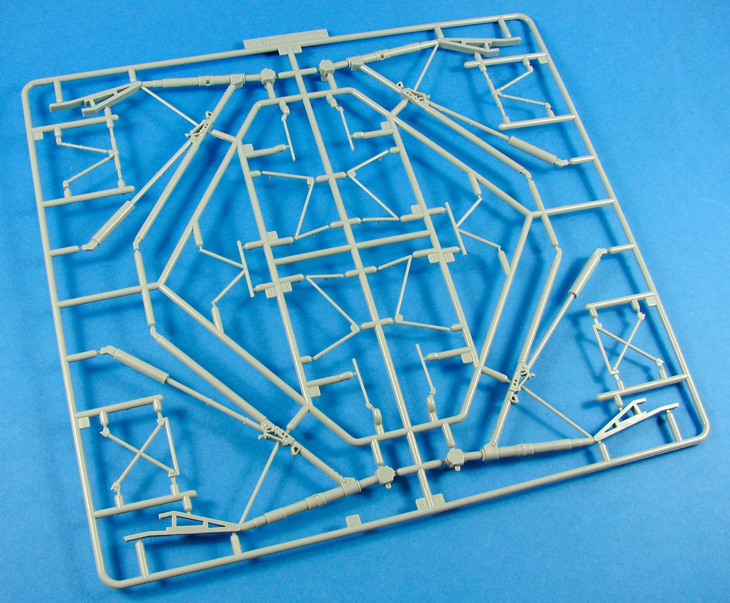
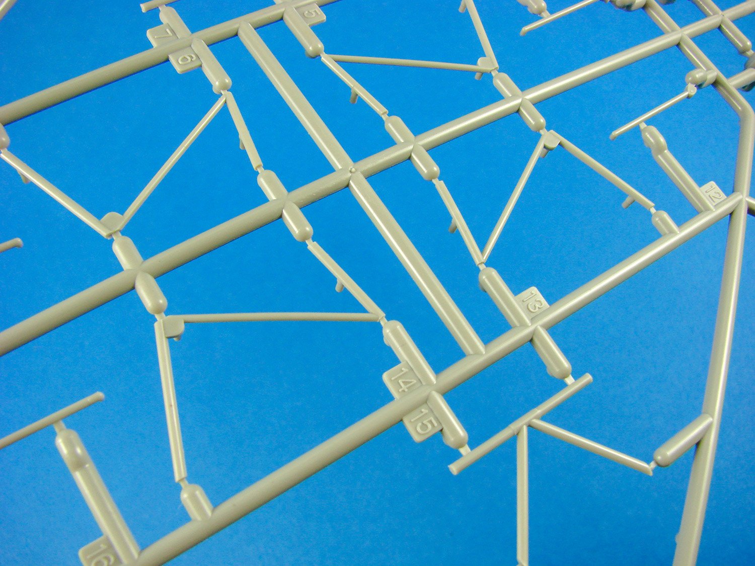
HK’s kit has FIFTY-ONE (fifty-five for Limited Edition) sprues, a number of which are interconnected on my sample, and may or may not be on the final production release. A number of these aren’t sprues in the most literal sense, but are themselves large, single pieces, such as the fuselage, nose and wings. Two standard clear sprues are included, and everything else is moulded in light grey styrene. The fuselage is split at a joint just inboard of the wing leading edge, as per the actual aircraft, which was sort of built in modules. As for the wings, these are moulded as a single piece, so no need to glue upper and lower halves together. This is produced in the same way as the Mosquito’s innovative single-piece wing. Wingtips are separate items, and these are again moulded as single-piece, hollow parts. Note the openings for the engine nacelle modules to be installed. The latter can be more or less completed and then plugged into the wing, complete with undercarriage for the inboard nacelles.


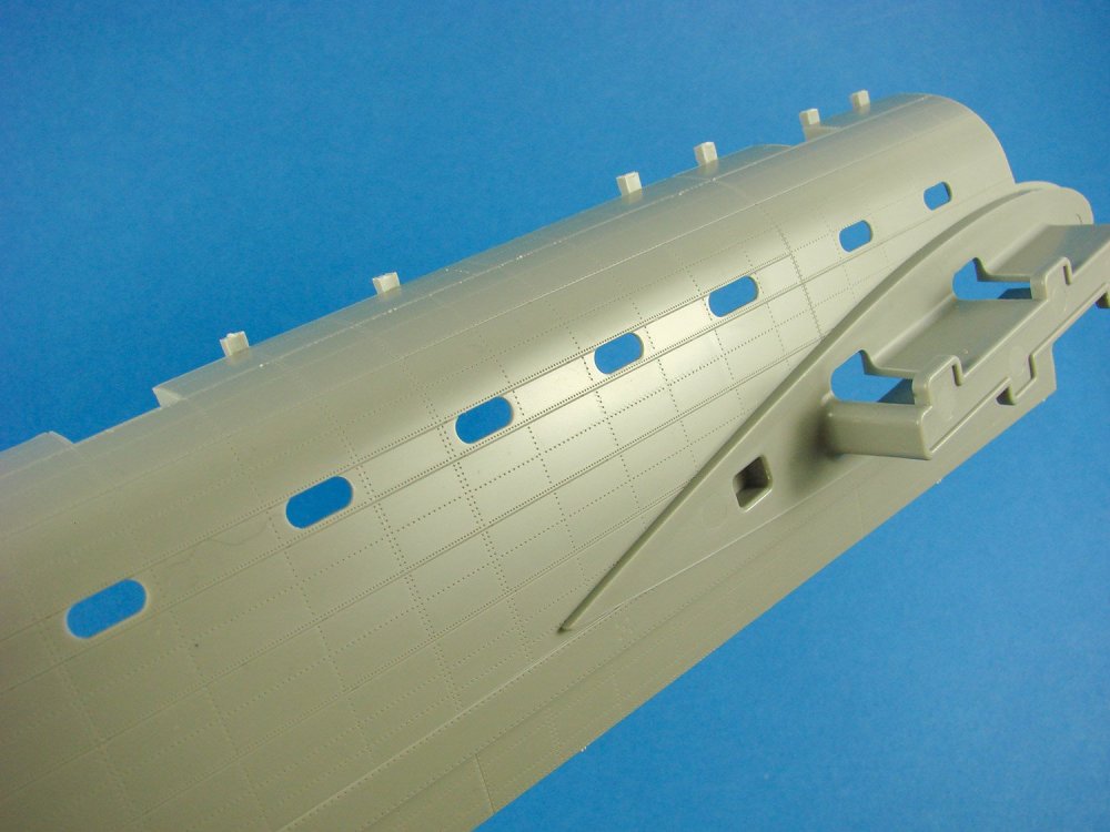
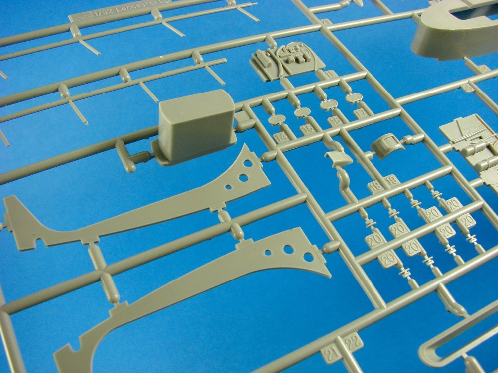
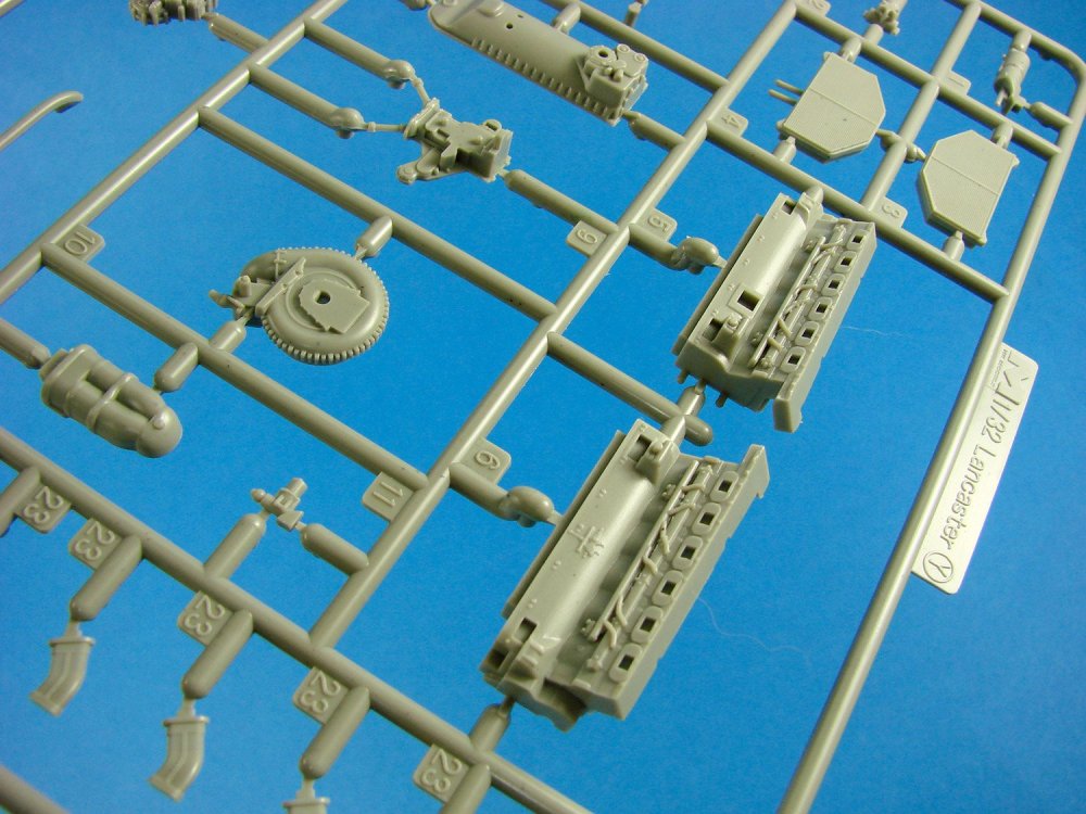
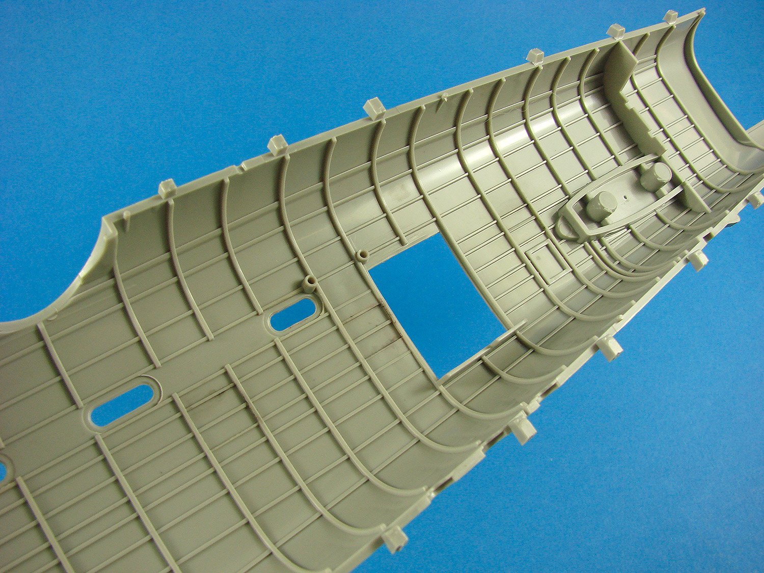
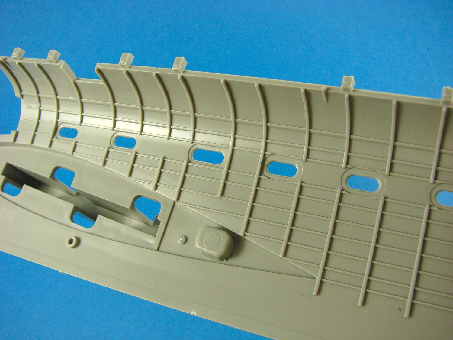
Whilst it was an original intention to depict oil-canning on the exterior surfaces, HK has decided not to take that approach, and have stuck to their fine panel lines and rivets finish as per today’s standard. The WNW kit will have the quilted appearance on their release which is scheduled for late next year. Internally, the Lanc’s fuse has a complete set of formers and stringers moulded in situ, with no pesky ejector pin marks that need removing. Instead, a series of tabs will need to be cut from the perimeter of these large parts, and a couple from selected windows. Fit of these large parts is excellent, and I can testify to the fit quality of the cockpit too as I built an early test shot just after Japan’s Shizuoka show.


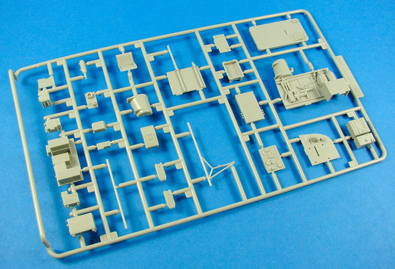
Internally, detail is excellent, with a fully fitted-out cockpit, radio operator, engineer, bomb aimer stations, as well as the infamous main spar which proved such an obstacle to crews which had to abandon their damaged aircraft. Ammunition containers, feed belts, doors to access rear turret, main hydraulics tank, flap jack, flare tube, turret hydraulic pressure recuperators, and even the Elsan toilet for those awkward in-flight moments! As you will imagine, the interior is spread around a number of sprues, and the completed model should look quite amazing. Note that the kit will come with some photo-etch, including such things as the seatbelts, but this test shot doesn’t have that.


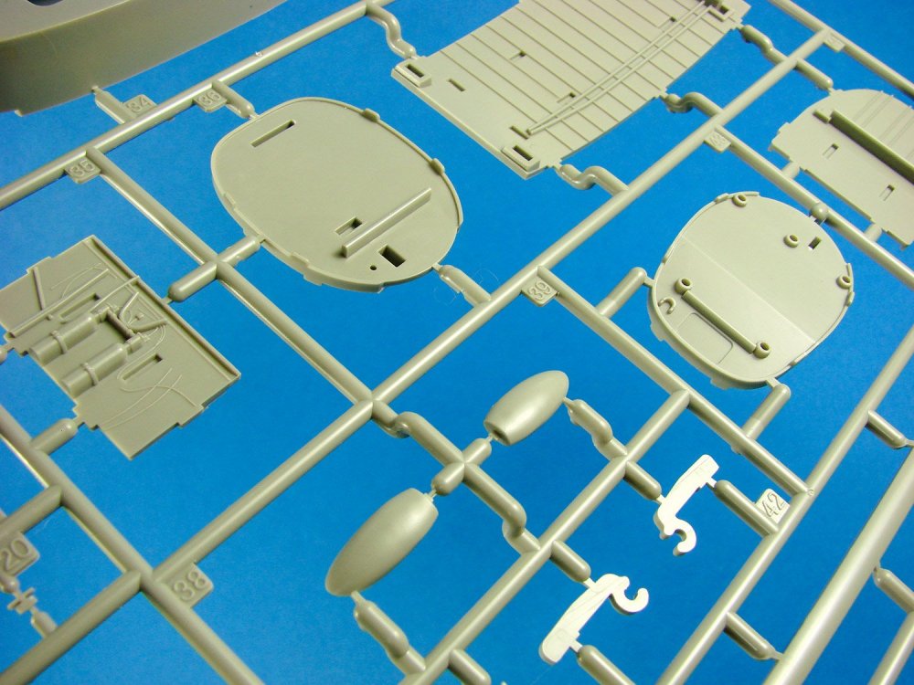

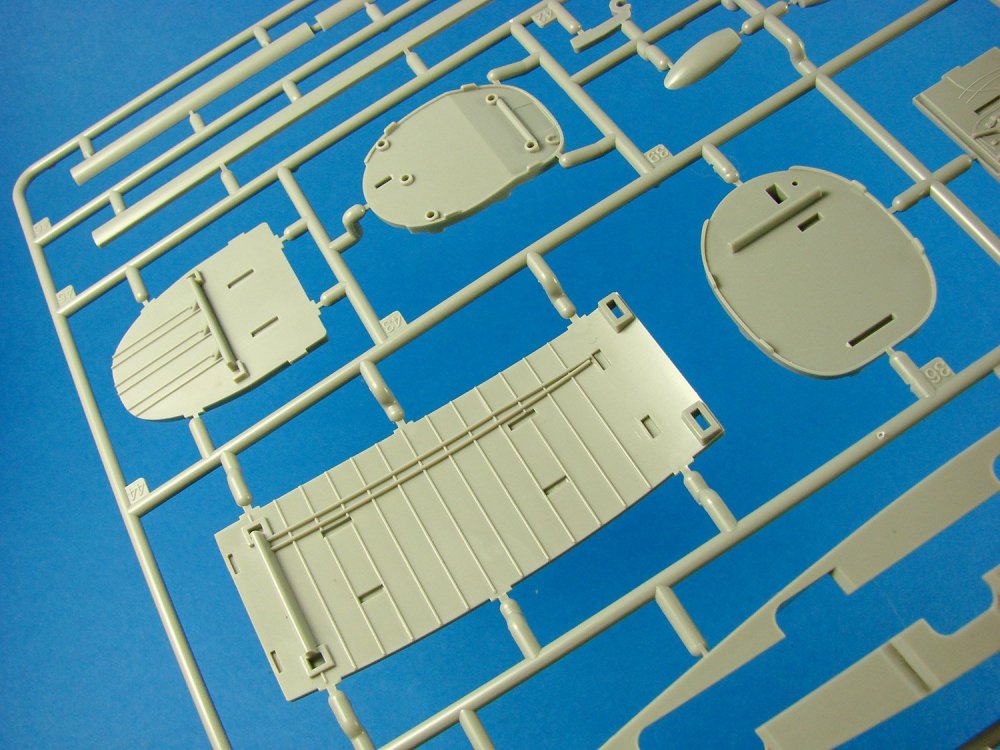

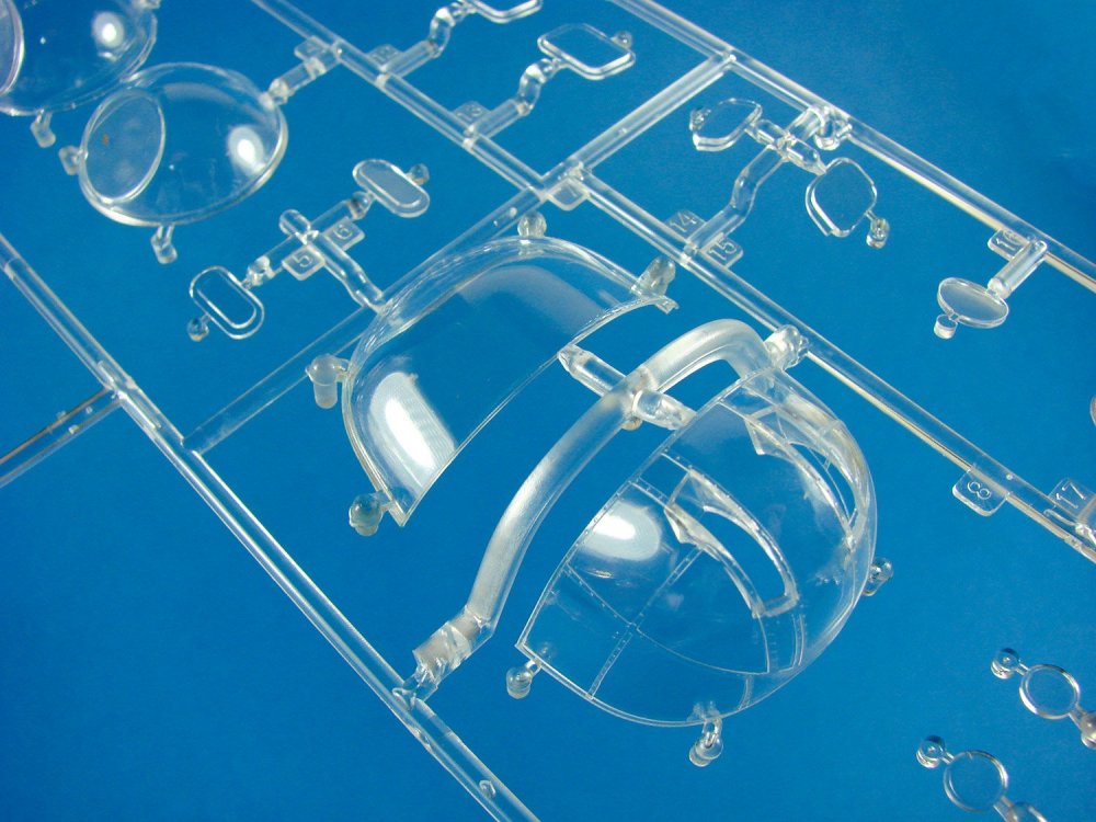
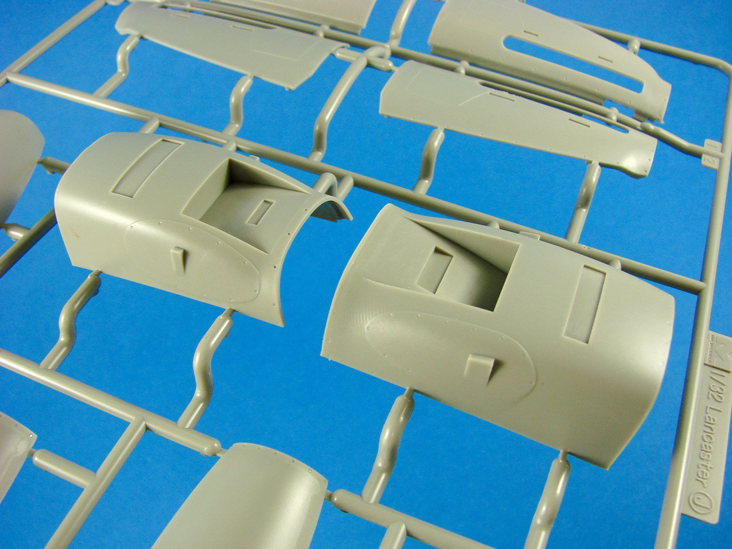
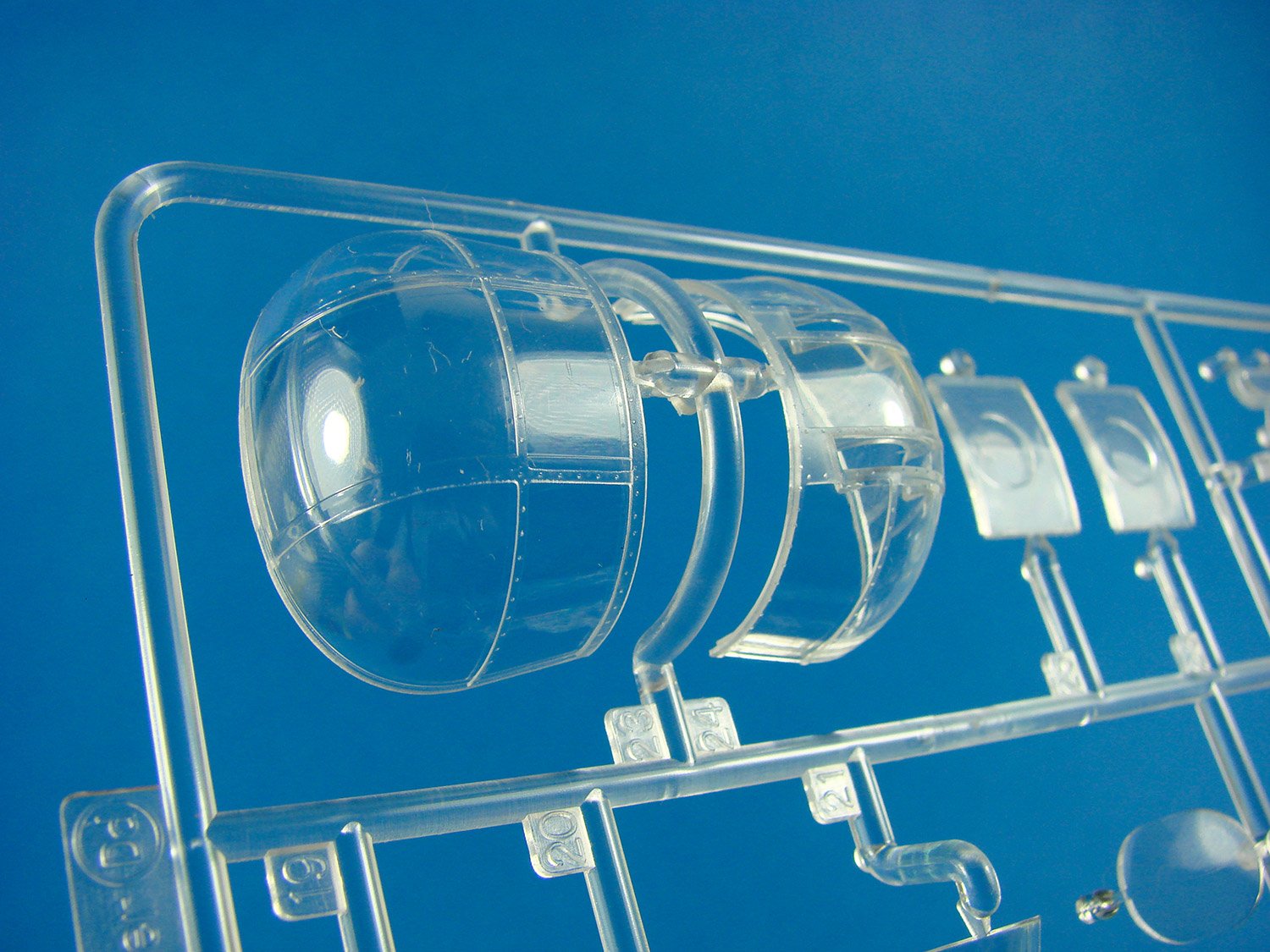
Those turrets are also nicely detailed within, and the joint lines on the forward and mid-upper follow a natural frame line. The rear turret glazing is moulded as a single piece item, and all turrets can be positioned/moved when installed. Barrels in this kit are moulded from styrene and the use of slide moulding has created hollow muzzles. Cooling slots are micely depicted. I do know that Master Model will produce a set of barrels specifically for this model. A small sprue contains the mid-upper fairing, and also a blanking plate, but the latter isn’t for use with this release. Another key external part that isn’t scheduled for use with this kit is the bulbous H2S housing that sits under the belly. So, it’s obvious that HKM has plans for the Lanc, as alluded to on the box art (Avro Lancaster Series).


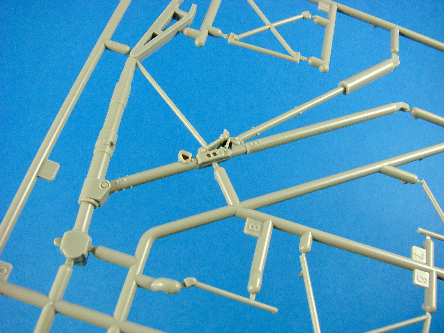
Four detailed engines are included in this kit, plus their respective oil tanks, mounts and firewalls. A little extra lead plumbing and wiring, and these will look very nice indeed. Of course, the intake radiators are included, with their very fine textured finish. Looking at the engine nacelles, HK do seem to have got the shapes correct after a failed few first attempts, so kudos to them for persevering with that. The nacelles, undercarriage and engine installations can be completed as separate units and then installed later. The appearance of the gaping mouth of the intake looks correct, and of course, the engine panels can be posed off the model to reveal the workmanship within. Exhausts are separately moulded stubs with semi-hollow, detailed ends, thanks to slide-mould technology. You will notice that both paddle and needle type prop blades are included, and both look slated for use with this release.


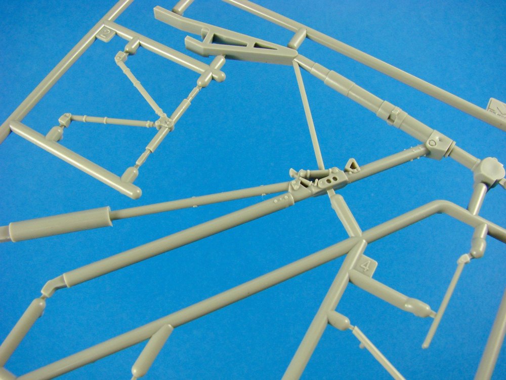


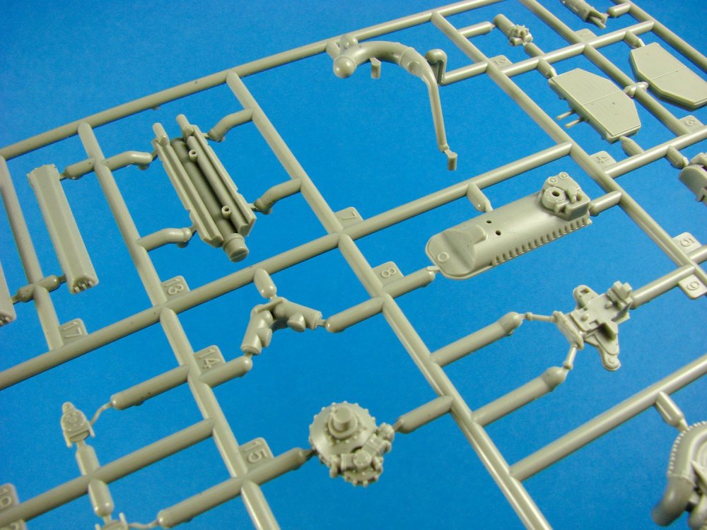
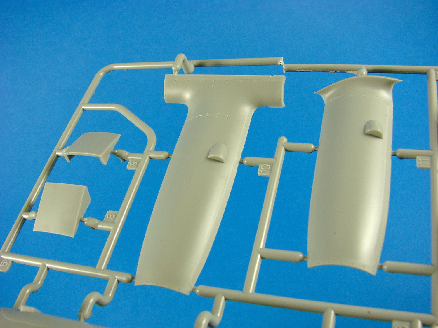
The flying surfaces of the Lanc are pretty large. To strengthen the tail areas, the inside of the parts have a series of ribs that will stop any accidental compression from cracking the seams, and also provide more basic rigidity. Elevators and rudders are moulded separately and can be positioned.


A large bomber needs a substantial payload, and this is supplied by means of 5 sprues of bombs and two which contain parts for the cookie. Plenty of construction work here to fit out the working face of the Lanc, but construction is very simple here. These are moulded with their plungers in situ, as well as fins, and you just need to add the ring to the fins. The instructions show the bomb bay doors and actuators being fitted at fuselage completion, which would be correct as the wings are separate modules which will install later.


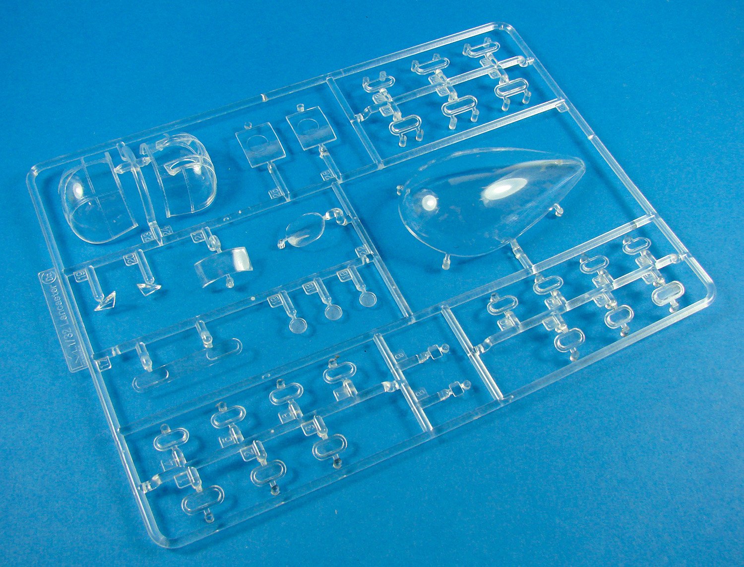
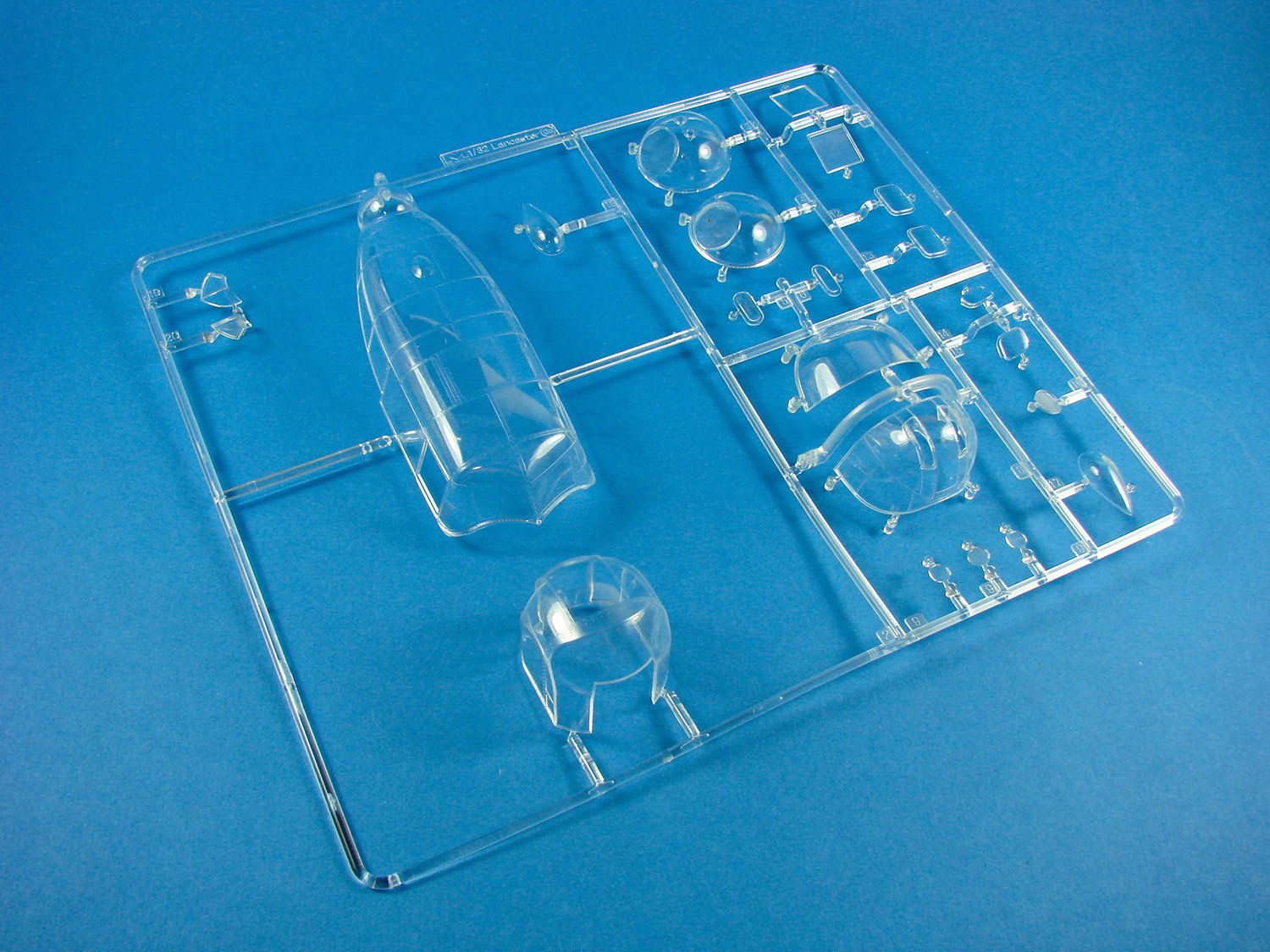
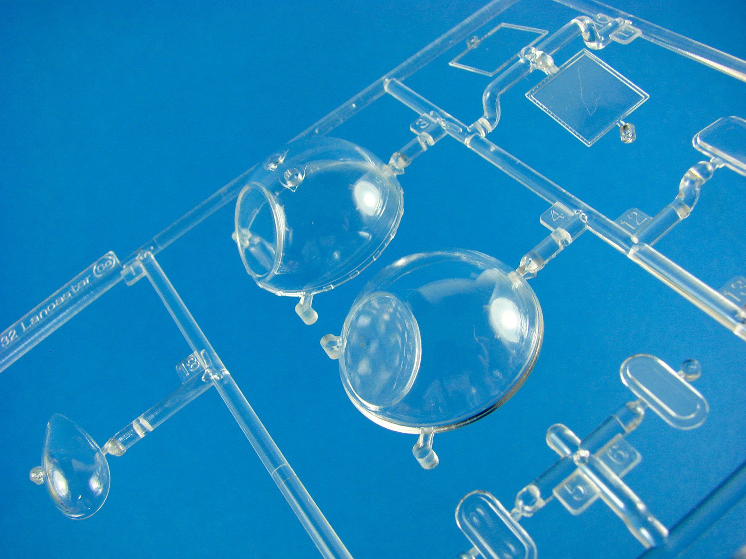
Clear parts are exceptional, with well-defined framing and no distortion, visually. Blisters are supplied to fit the main canopy sides, and the forward side canopy windows are separate too. Note that two different bomb aimer blisters are included in my sample, with only one for use with this specific release. I don’t know whether these extra unused parts will be supplied in the general release.


My sincere thanks to HK Models for sending out this test shot for this article, and to build for the Military Illustrated Modeller magazine. In the meantime, check out the Facebook page for building the 1:32 Avro Lancaster, here: https://www.facebook.com/groups/LancAssemblyLine/

-
12
-
-
Not at all. Ours will be in the next day or so.
-
2
-
-
HKM Lanc sample here. Photos this weekend.
-
3
-
-
There's a slight chance it will be here today, but failing that, possibly Monday. It's out for delivery now with DHL, but I can't update my Safe Place option for delivery.
-
1
-
-
Holy crap! Now I LIKE that! Makes me want to get adventurous with resin myself (if only my mag deadlines allowed)
-
4
-


1:32 Kawasaki Ki-45 Kai Tei Type 2 "Toryu"
in Aircraft Reviews
Posted
1:32 Kawasaki Ki-45 Kai Tei Type 2 Two-Seat Fighter "Toryu"
Zoukei-mura
Catalogue # SWS13
Available soon from Volks Japan/USA
The Kawasaki Ki-45 Toryu (屠龍, "Dragon Slayer") was a two-seat, twin-engine fighter used by the Imperial Japanese Army in World War II. The army gave it the designation "Type 2 Two-Seat Fighter"; the Allied reporting name was "Nick". In response to the rapid emergence in Europe of twin-engine heavy fighters such as the Messerschmitt Bf 110, the army ordered development of a twin-engine, two-seat fighter in 1937, and assigned the proposal by Kawasaki Shipbuilding the designation of Ki-38. This only went as far as a mock up, but by December of that year, the army ordered a working prototype as the Ki-45, which first flew in January 1939. Results from the test flights, however, did not meet the army's expectations. The Ki-45 did not enter service, but the army, insistent on having a working twin-engine fighter, ordered Kawasaki to continue development. Kawasaki responded by replacing the engines with the proven Nakajima Ha-25.
The Ki-45 was initially used as a long-range bomber escort. It was subsequently deployed in several theatres in the roles of interception, attack (anti-ground as well as anti-shipping) and fleet defence. Its greatest strength turned out to be as an anti-bomber interceptor, as was the case with the Bf 110 in Europe. In New Guinea, the IJAAF used the aircraft in an anti-ship role, where the Ki-45 was heavily armed with one 37 mm (1.46 in) and two 20 mm cannons and could carry two 250 kg (550 lb) bombs on hard points under the wings. Soon after entering service, the Ki-45 was assigned to home defence, and several were dispatched against the Doolittle raid, though they did not see action. The craft's heavy armament proved to be effective against the B-29 Superfortress raids which started in June 1944. Eventually the end aircraft were used effectively in aerial ramming attacks. They were also used in kamikaze attacks, such as the attack on USS Dickerson on 2 April 1945 off Okinawa. In 1945, forward and upward-firing guns showed some results with the commencement of night time bombing raids, but the lack of radar was a considerable handicap. By the spring of 1945, the advent of American carrier-based fighters and Iwo Jima-based P-51s and P-47s escorting B-29s over the skies of Japan brought the Ki-45's career to an end. 1,675 Ki-45s of all versions were produced during the war.
The kit
As I write, straight after Scale Model World 2018, this kit isn’t slated for general release until late December. The kit I have with me is a full production version, with the exception of the instruction manual which has been printed in-house at Zoukei-mura in order to fulfil their SMW pre-order commitment. I, of course, picked this kit up from their booth, at this show and began my article as soon as I got home. This project has taken around 4 ½ years from start to release, so let’s tuck in and see what we have.
The Ki-45 Toryu is packed into a rather large and heavy box that has a hell of a lot of rigidity to it. This is because ZM supply a complete corrugates box with integral lid, and the product lid sits over the top of this. Zoukei-mura’s artworks are always very attractive and this one is no exception, depicting a Tai-Atari machine (Special Attack) flying underneath a B-29. These machines were stripped of defensive weaponry and used to ram bomber formations in a form of Kamikaze attack. So yes….’special’attack! Images on the side of the super-glossy product lid depict the internal details of the Ki-45, and they sure look impressive. Lifting the tabbed lid reveals a box that’s crammed full of styrene. There are TWENTY-FIVE sprues in this package, with SIX of these being in clear plastic. Of the latter, four of those are frosted clear duplicates of main airframe sprues, with just one being crystal clear for the canopy parts, and another containing windows and airframe lights etc . The rest are moulded in light grey styrene. You could almost build an entire external airframe from the left-over parts. It’d certainly be useful to acquire the remaining sprues and build another, if it was cost efficient enough to do so. All sprues are individually packaged too…even where multiples exist. This is the standard that we should expect from all manufacturers.
As this kit is just on the cusp of full release, there was no instruction manual in the package, and this was given to me at the show, along with the decals and vinyl mask set. The instructions themselves aren’t final standard, and are printed in-house, but are still every bit as good as the finals. There are no photo-etch parts in this kit, as ZM like to produce the detail using just standard kit parts. I don’t doubt that their own range of PE will eventually be released for those who like to adorn and detail their models further.
Sprue A (1 x grey, 1 x clear)
Here we have the fuselage sprue, with this particular unit broken down into port and starboard sides, with a separate forward belly and upper spine. The nose is also separate, but on a different sprue. Zoukei-mura has also engineered this with separate wing fairings that recess into the fuselage sides. The fairings themselves are provided as upper and lower parts. Externally, the fuselage isn’t resplendent in rivets, but it does have key lines of them following the nicely recessed panel lines, with rivets and fasteners around areas such as the tailplane fairing and access ports. There are even rivet lines in the area which will be encapsulated by the wing root fairings and wing. Internally, all of the formers and stringers are represented, as well as some avionics and wiring looms. There are a small number of ejector pin marks inside, but they do look like they will be obscured by the various assemblies and equipment. The internal structures are equally as good in all of the various fuselage sections, producing a fully detailed interior.
The area between the pilot and gunner is also a separate part, with holes into which the various panes of clear plastic will install. Note also a separate instrument coaming, removing the need to erase tricky seam lines in this area.
Also on this sprue are the aerial mast, landing flaps with internal structural details, and single-piece ailerons, with superbly thin trailing edges.
This sprue has also been supplied in clear styrene, should you wish to use such parts to partially display the interior.
Sprue B (1 x grey, 1 x clear)
As with the previous sprue, one of these is supplied in clear as well as grey. This is where we get to see the wings. These are moulded as conventional upper and lower panels, minus the forward engine cowl fairing and undercarriage nacelles. Landing flaps and ailerons are also separate and were seen on the previous sprue. Note again how the selected rivet lines chase the finely engraved panel lines only. If you want to make a weathered and beaten up example, you may consider adding extra rivet lines that you can use as points of paint chipping etc. Very nicely represented are the raised rear engine cowl fairings. As with the landing flaps themselves, the upper wing panels have the interior constructional detail moulded within them.
Leading edge lights etc. are to be fitted separately, hence the cutaways in this area.
Sprue C (1 x grey, 1 x clear)
Proving that the whole exterior airframe can more or less be built twice, this next key sprue is also provided in both grey and clear styrene. Note that the tailplane is moulded full-span and the lower panel is recessed so it fits neatly into the tailplane fairing on the fuselage. You will also notice that the upper panel is recessed. This is because the fin is moulded separately and contains part of the upper fairing, which again sits into the tailplane recess. Lovely engineering. The elevators are also to be found here, and are moulded as upper and lower halves, which is unusual seeing as the ailerons were single-piece units. You will also find the rudder and its actuators on this sprue.
There are a number of options when it comes to the instrument panel. The one on this sprue is for a panel moulded with blank, recessed instrument faces. A decal is supplied for this, and it does look very good, and indeed much better than those that ZM used to provide with their kits. For this to work effectively though, I would look at punching out the dials and sitting them individually in the recesses.
If you flip the sprue over, you’ll note that the tailplane parts actually have real aircraft constructional elements within them, which are designed to be seen when you use the clear sprue options. Ideally, you should try to paint those to make the appearance more realistic.
Sprue D
This is one of two totally transparent sprues in the kit, containing parts for the canopy. ZM has provided an option for both open and closed canopies for both crew positions. This means the forward windscreen and hood is moulded as a single piece for the closed option, and likewise the rear canopy is provided as a single, closed part. If you wish to pose them open, that rear canopy is moulded as a single piece again, but with the canopy folded sideways. The pilot’s hood is provided as two parts which are assembled on a jig to get the correct folded angle before you attach to the fuselage. Another very nice little touch. Canopy frame lines are well-defined and should be very easy to mask up to with the vinyl mask set (although I’m a bigger fan of tape masks).
Sprue E (x2)
E is for ‘engine’, and here we have everything you need to build two complete Mitsubishi Ha-102 14-cylinder radial engines, minus their exhaust systems. I’ll explain that rationale later. These really are amazingly detailed, right down to the crankcases and cylinders containing the pistons in various states of compression. You can’t see any of this when assembled, of course, and it is a bit of a gimmick, but impressive nonetheless. Details are filigree in execution with superbly fine cooling fins on the cylinders, bolt head details on the reduction housing and the textures applied to the annular radiator parts. Even the prop shaft is keyed, so you can pose the model with the prop removed.
Auxiliary details are also perfectly represented, such as the magneto, turbine housing, carburettor, and attenuator etc. The only thing you will really need to do is to add the ignition wires, and you should have a very authentic replica of this engine.
As is now de rigueur with ZM kits, the engine sprue has a neat little trick up its sleeve. Parts are moulded within the sprue parts themselves, that when cleaned up and assembled, will create a rather nice display stand for the engines. These will be very useful if you wanted to display an engine next to the aircraft instead of installed. In the back of the instruction manual, there is a price list given (in Yen) for specific sprues, so you could always purchase another, should you wish to build a third engine and display that instead of sacrificing an airframe unit.
Sprue F (1 x grey, 1 x clear)
I’m not sure why there is a grey sprue included here, as well as this clear one, as this contains such things as windows for the upper fuselage between the pilot and gunner, as well as wingtip lights, airframe lights, wing leading edge lenses etc. Unusually the pitot is on here too! Whatever the logic, the parts are crystal clear, as with the main canopy set, and superbly moulded
Sprue G (1 x grey, 1 x clear)
Another large sprue for which an identical clear alternative is supplied. The main players here are the engine nacelle halves and the forward engine cowl ring, cowl panels, and engine – wing fairings. You’ll also note the main gear doors which are moulded with inner nacelle structural elements attached. This will create a rock-solid gear door to nacelle joint. Detail on the various cowl and fairing panels is excellent, with nice louvre details (although not open), panel line, fastener and rivet details, as well as
There are some differences in nacelle assembly, depending on which machine you build, and these tend to centre around the intake areas and engine mounting housings which are moulded on other sprues. However, what you will find here are the options for the Tai-Atari open and closed cowl flaps and the oil cooler for the same version.
Internally, the structural items have details that correspond to their construction, as per the fuselage interior.
Sprue I
You get a sense of the size of this model when you see the main wing spar which is almost full span. This isn’t really typical of the real wing interior as it doesn’t have much in the way of ribs etc. and is only representative. However, it does provide a solid base for the wing assembly, and also to fit the inboard wing fuel tanks. The centre section though, represents the area between crew stations, and is raised above the regular floor so a fuel tank can be installed within. With the cockpit floor in place, you’ll only be able to see that tank through the wing rib structures which will sit either side of the tank. These will be glimpsed through the nacelles.
We now also start to get an idea about how the cockpit will be fitted out, and the detail involved. As well as bulkheads with plumbing/wiring details, we have avionics units, console units, gas levers, multipart pilot seat with a superbly detailed and moulded lap strap, armour plate, gunner seat with separately moulded lap strap, control stick and spade grip, forward cockpit floor, floor mounting frame, side wall frames with wiring and avionics units, and both propellers with integral hubs. Hey, we’ve nowhere near finished with cockpit detail either, as there’s more on another sprue! You’ll also note that another instrument panel option is provided here too, and this time as a unit with moulded instrument detail. This, for me, is my least favourite option as I’d rather go for the version with blank instruments as it looks far more 3D in appearance.
Sprue J
The main cockpit floor is moulded here, and it’s upon here that the centre wing fuel tank is mounted, and both cockpits are constructed. Here you can see some nice raised riveting and more plumbing too. This should look great when weathered and washed. Engine – nacelle mounting housings are also found here, although these are specifically for the Tai-Atari machine and not suitable for Late Production due to the cut-out shapes for the oil cooler etc. Also note cockpit side console part in this photo. The exhaust manifolds for the Tai-Atari are also moulded here.
Unfortunately, the instructions don’t denote parts that aren’t scheduled for use with this release, and no matter how hard I look, I can’t find this two-part fuel tank installed anywhere. There will be future versions of this kit available eventually, so I suppose these will be for those. Not all optional parts on this sprue are for the suicide machine. Along with parts from Sprue K, parts here are included to build the Ho-203 37mm nose cannon pack. Nice use of slide-moulding has been incorporated so produce hollow muzzle and muzzle socket.
Other parts on this sprue include the empty cartridge collection box, oxygen tanks, ammunition magazines, radio mounting frames, magazine racks, bulkheads, cannon base, etc.
Sprue K
This small sprue contains detail parts such as rudder pedals and rudder pedal bar, flap lever, landing gear lever, seat adjustment lever, tailwheel locking lever, console levers, oil reservoir, oxygen bottle, gas pressure tank, Type 99-Hi-2 radio, fuel gauge toggle switch, auxiliary instrument panel, plus more parts for the nose cannon pack.
Sprue L
You’ll need to be real careful with this sprue as the components on it are pretty fragile. Here we have linkage rods for things such as the rudder and elevator. These are very finely moulded and the biggest job here is to remove the connection points as the seams are negligible.
Sprue M
Another small sprue. This one holds the options for the rear seat base, although it does look like only one of these sets of parts is needed for this specific release. Parts exist here for the gun ring truck, rear cockpit bulkhead, tail wheel bulkhead and fin attachment point and also the tailwheel.
Sprue N
ZM certainly like to pack as many details into their subjects as possible, and this small sprue contains many more of those details, such as oil pump lever, cannon hydraulic control cock, fuselage underside bulkhead, tail gear support lever, tail strut oleo scissor, electromagnetic control box, etc. A number of parts on this sprue also seem to be for a future version of the kit, such as the machine gun for the rear cockpit (not fitted on this release).
Sprue O
Only one part here, and that is for a linkage rod which extends from the cockpit to both wings, presumably for aileron control.
Sprue P
If you’ve ever fiddled with tricky tubular frame mounts for engines, and wondered whether all the angles were correct, then you’ll have no such worries with this kit. Both engine mounts are moulded as single, complete pieces, complete with mounting ring. The moulding is particularly impressive. Equally as impressive are the main gear struts with their integral mounting points and retract mechanisms. Also included are the brake lines.
I’m surprised that ZM haven’t chosen to add weighted tyres in this kit, as seems to be becoming more of an industry standard. Here, we find those wheels, moulded as traditional halves, minus the hubs. Note also the small leading-edge fuel tanks in this photo.
Other parts on this sprue are the oil tanks, nacelle bulkheads, wheel hubs, torque arms, landing gear door links, and fuel cooler etc.
Sprue Q
As well as a couple more pieces pertaining to the main undercarriage, this sprue contains the inboard wing fuel tanks (moulded as halves), auxiliary fuel tanks, engine firewalls and the wing ribs that will be seen inside the landing gear nacelle, moulded with what I presume are either hydraulic or fuel line detail. Engine bulkhead detail is equally as impressive, with various wires and plumbing lines running from point to point and through to the rear of the bulkhead.
Sprue S (1 x grey, 1 x clear)
Cowl parts and radiator flaps in both open and closed positions, are moulded here. These are for the Late Production machine, and are resplendent with detail internally too.
The nose cone is pretty obvious in this photo, moulded as a single-piece unit, with the cannon aperture in the tip. More cowl parts are moulded here, as well as the Late Production oil cooler.
The last part of the fuselage can be found here in the shape of the spine that sits between the pilot and gunner. Into this will fit the various glazed panels and you’ll also note the slots through which the upward firing guns will protrude. Adjacent to this is the solid metal fairing that encloses the rear cockpit position opening that would be fitted with a rear facing gun in earlier versions of the Toryu.
As with a number of other sprues in this release, this one is also provided in clear.
Sprue T
Our last sprue concerns the Late Production version, with parts to build the Shräge Musikupward-firing gun pack. Note the Ho-5 20mm cannon which are amazingly detailed and moulded as halves, ammunition box, spent cartridge box and feed chutes. Cannon muzzles are hollow due to being slide-moulded. Adjacent to these are the exhaust parts for this version, again moulded with hollow ends.
The different exhaust and oil cooler system for the Late Production calls for a different engine mounting fairing, as can be seen on this sprue. Other parts include hydraulic pressure control unit, cannon support bulkheads, magazine rack, spare magazine rack etc.
Masks
A small sheet of green vinyl is supplied, including masks for all the canopy and glazed areas. I’ve found this material from ZM a little hit and miss with it starting to peel after being applied for a short while. I still prefer kabuki-style masking material, as supplied by the likes of Eduard.
Decals
I find that some Japanese decals are a little thicker than what I’m used to, and ZM’s fall within that category, although my experience in applying them has yielded little trouble. These are too a little thicker I am used to, but are indeed printed by Cartograf, and are superbly printed, and the instrument decals are also worthy of use, unlike some of their previous kits where they had little definition. They are also super-glossy. ZM has provided decals for the various white and yellow areas/bands of the model, and I would airbrush these instead of resorting to decal use. I would also airbrush the Hinomaru too, and maybe only use the instrument, emblems and stencils. Everything is in register, and carrier film is minimal.
The two schemes supplied are:
Instructions
As I initially stated, this is not the professionally printed version which will be included with the full release, but you really couldn’t tell! Mine is glossy and stapled, and still worthy of being called final. This A4-size manual has 60 pages, with construction broken down into 5 chapters with dozens of sub illustrations etc. You do get a feeling of sensory overload when you first look at a ZM instruction manual, but they are not only very informative with regards to the many drawn illustrations, but they also contain great annotation, part names, and also notes on the real aircraft, as well as a few photos of the model for clarity. You will need to keep your wits about you with regard to the various parts options, to ensure your model is an accurate representation of the machine you choose to build. There is also a very good history of the type and notes on its design. Later in the manual, a drawing illustrates one of the schemes, whilst a finished model exhibits the second scheme. Paint references are provided throughout for Vallejo and Mr Colour paints. A parts map is also included in the rear of the manual.
Conclusion
After looking at initial CAD and at the 3D-printed models that have been on display, I sort of had an idea about what to expect from this release. Or at least I thought I had. In reality, the kit is far nicer than I envisaged, and certainly far more detailed than I expected, even from ZM. The cockpit and gun areas are simply astounding, and the engines and nacelle details match that assessment. There are of course TWO versions of the Toryu that can be built from this kit, and they vary significantly in equipment. The Late Production, whilst having the plainer scheme, has the underwing tanks, Schräge Musik-style gun pack, and the nose cannon, plus the more complicated exhaust arrangement. This for me is the one that really appeals to me, whilst some will doubtless prefer the slightly stripped version with the green camouflage patches. It could well be a tough call! Everything about this release is quality, right down the instruction manual. You will need to have your wits about you with the manual due to the sheer amount of info given, but it really is quite something to study, and study it you reallymust. I really can’t wait to pile into this and build my first Japanese fighter since I was a kid!
Review sample courtesy of my wallet and my Telford pre-order. Thanks to the guys at ZM for the chat, and I look forward to that Hs 129!")
Watch out on the Volks Japan/USAsites for this kit becoming available. Also watch out for this in a future issue of Military Illustrated Modeller, where I’ll be building the Late Production version.