


James H
-
Posts
3,255 -
Joined
-
Last visited
Content Type
Profiles
Forums
Events
Gallery
Posts posted by James H
-
-
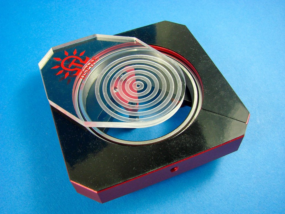
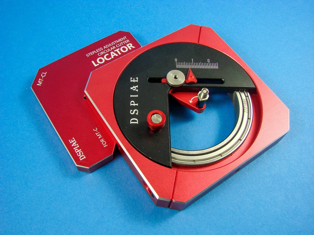
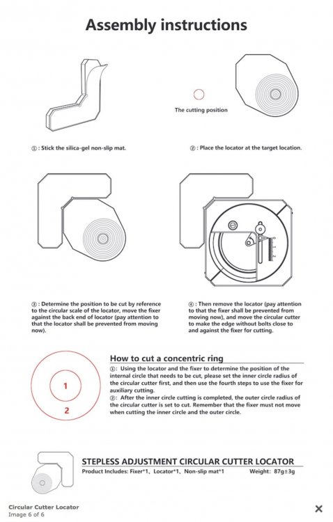
Stepless Adjustment Circular Cutter Locator
DSPIAE
Catalogue # MT-CL
Available from Breveco Modellingfor 18,50€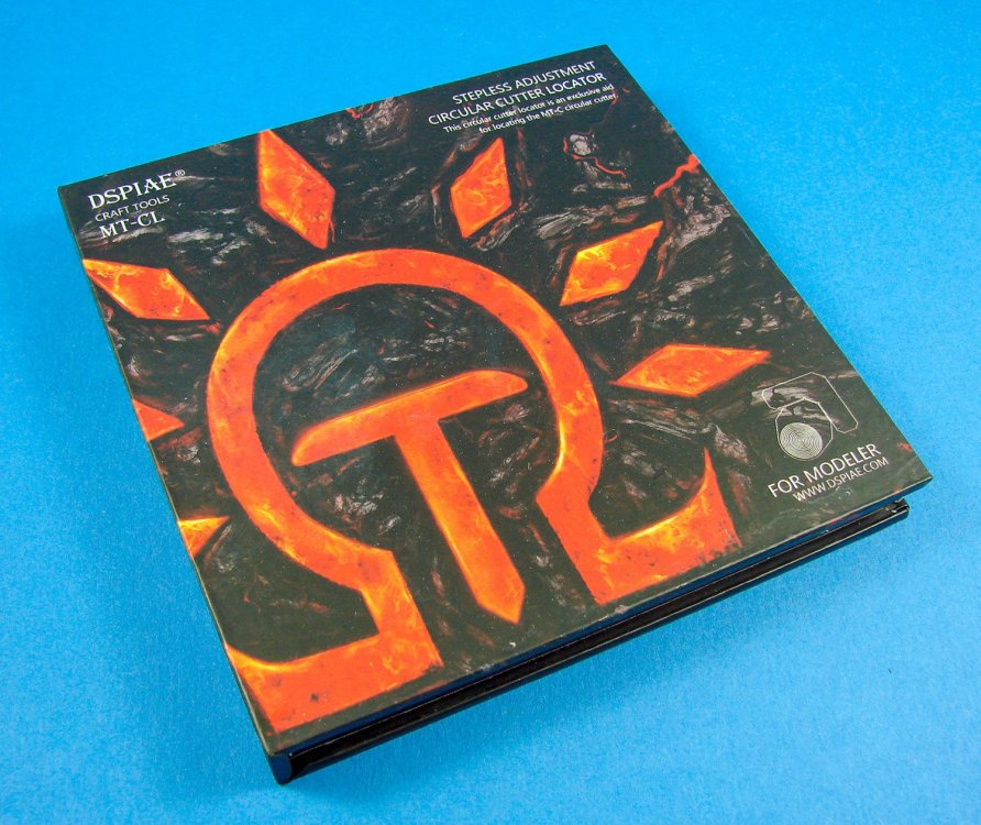
Some product names just roll off the tongue, and some don’t. This one definitely falls into the latter category, being called a ‘Stepless Adjustment Circular Cutter Locator’. For the purpose of this article, I’ll just refer to it as a ‘Locator’. This is designed to be used DSPIAE’s equally tong-twisting product, the Stepless Adjustment Circular Cutter, reviewed here.
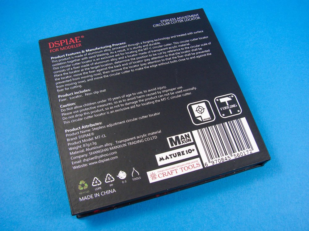
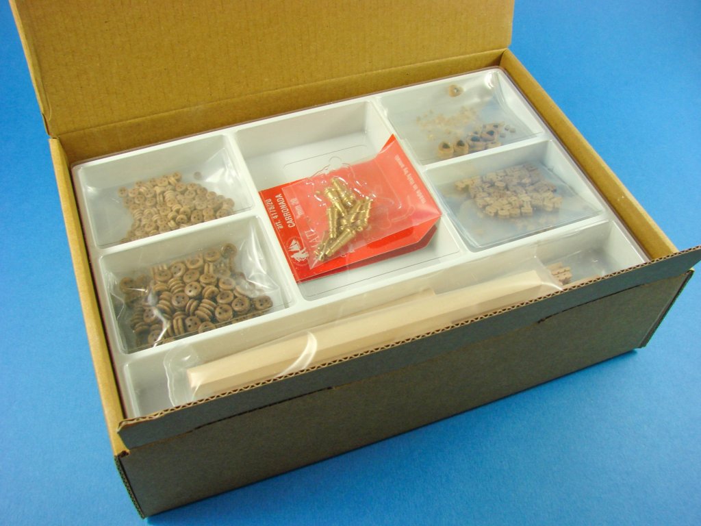
Like the other products that we’ve seen from this Chinese manufacturer, this is also packaged into an almost bomb-proof box that is constructed from MDF and then decorated for their unique and eye-catching brand that looks like something from a lost civilisation from South America! The back of the box has some rudimentary instructions and a description of what this tool actually does. In short, I’ll describe roughly what this accessory will do in conjunction with the circle cutter.
I see this tool as having a number of similar functions. The most basic is to roughly locate the cutter on your masking film or masking tape media, allowing the modeller to maximise that material and reduce waste. However, there is a more significant reason for using this and that is to create concentric discs of masking material, allowing the modeller to create things such as roundels or masks for tank/aircraft wheel hubs etc. So, instead of just ripping away and making discs with the circle cutter, we now have a way to use it more completely as a tool and fulfilling its potential.
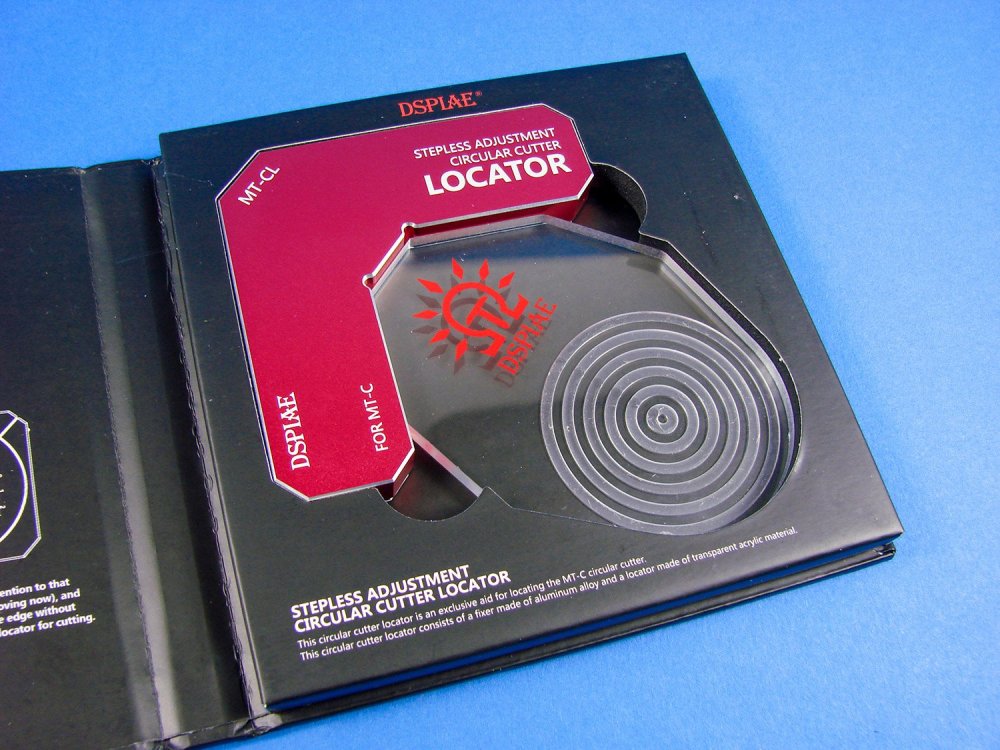
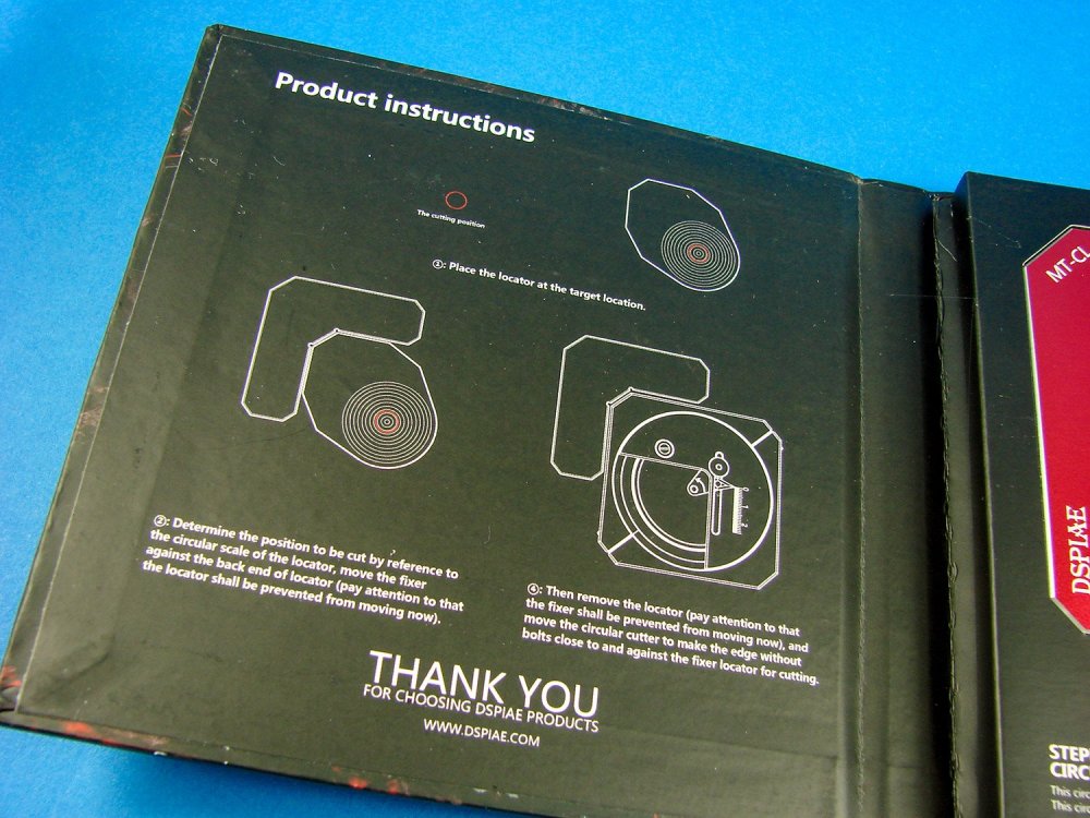
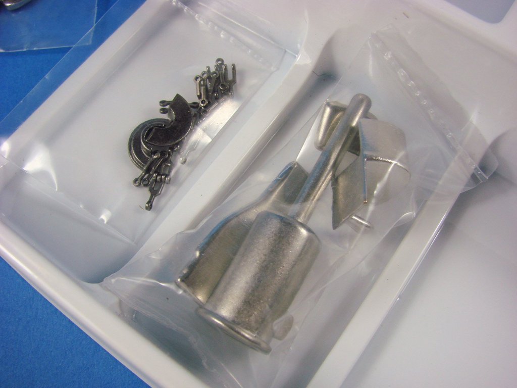
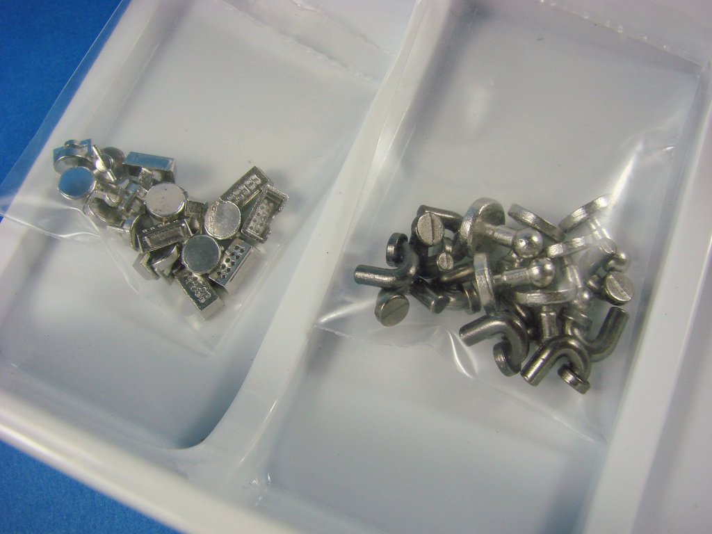
Opening the box, we see a cardboard and foam cut-out into which the main components are sat, and on the opposite side, inner lid, we have a couple of instructional images. One of the components, a clear acrylic guide that sits into the L-shaped Locator, firstly sets the central position of the circle you will cut. There are grooves in this that, whilst not calibrated, help give the modeller the centre of the circle to be cut. You can of course measure that on the guide and perhaps mark it for future use. The acrylic guide is a perfect and exact match to the circle cutter, from its centre to the outside corner. Once you remove the guide, you can then place the cutter into the Locator and start your work!


As the Locator provides a perfect reference point, you can now set the circle cutter for larger and smaller circles, and they will all be perfectly concentric! The shape of the cutter allows this, unlike the circular Thinnerline product which would take more effort to produce the same work.

The Locator itself is made from red anodised aluminium allow and is extremely robust. When you remove this from the box, you’ll note a self-adhesive rubber base which needs to be peeled and affixed to the Locator.
It really is as simple as that.
Conclusion
Whilst I was extremely impressed with the circle cutter itself, this new addition really gives it a new lease of life and allows to me make roundels etc. on the fly, and thus for me to mask and paint more of my markings. A very high-quality tool that is relatively cheap to buy and increases your options if you have the cutter. If you don’t own the cutter, I really suggest you purchase one and add this extra tool to your shopping cart. Just amazing!My sincere thanks to Breveco Modelling for sending this out for review on LSM. To purchase directly, click the link at the top of this article.

-
You should market it!
-
 2
2
-
-
We sure are! Build away!
-
1
-
-
This is one kit that really appeals to me. I love the interior stuff, and this one looks like it's been designed by Trumpeter's A-Team.
-
2
-
-
Thanks Peter,
I'll be posting an unusual project in the next day or two.
-
3
-
-
New registration notifications were being blackholed. Now fixed!
-
Hi guys,
Always good to see familiar faces here at LSM. Now, get some builds posted up and make yourself at home!

-
3
-
-
Please check now.
-
1/35 Sd.Kfz.251/1 Ausf.A
ICM
Catalogue # 35101
The Sd.Kfz. 251 (Sonderkraftfahrzeug 251) half-track was a WW2 German armoured fighting vehicle designed by the Hanomag company, based on its earlier, unarmoured Sd.Kfz. 11 vehicle. The Sd.Kfz. 251 was designed to transport the Panzergrenadiers (German mechanized infantry) into battle. Sd.Kfz. 251s were the most widely produced German half-tracks of the war, with at least 15,252 vehicles and variants produced by various manufacturers and were commonly referred to simply as "Hanomags" by both German and Allied soldiers. There were four main model modifications (Ausführung A through D), which formed the basis for at least 22 variants. The initial idea was for a vehicle that could be used to transport a single squad of 10 Panzergrenadiers to the battlefield protected from enemy small arms fire, and with some protection from artillery fire. In addition, the standard mounting of at least one MG 34 or MG 42 machine gun allowed the vehicle to provide suppressive fire for the rifle squad both while they dismounted and in combat.
The armour plates were designed to provide protection against standard rifle/ machine gun bullets (like the 7.92×57mm Mauser bullet). The front-facing plates were 14.5mm thick; the sides were steeply angled, V-shape 8mm thick plates. This level of armour provided protection against normal (non-tungsten) rifle AP round, which could pierce about 8mm of vertical armour. Positive aspects of the open top included greater situational awareness and faster egress by the infantry, as well as the ability to throw grenades and fire over the top of the fighting compartment as necessary while remaining under good horizontal cover. The downside was a major vulnerability to all types of plunging fire; this included indirect fire from mortars and field artillery, as well as small arms fire from higher elevated positions, lobbed hand grenades, even Molotov cocktails, and strafing by enemy aircraft. There were 23 official variants, and sundry unofficial variants. Each variant is identified by a suffix to the model number, however, there was some overlap in the variant numbers. The Sd.Kfz. 251/1 Schützenpanzerwagen was a standard personnel carrier, and the Ausf.A Ungepanzerte. This was made with plain steel 5mm plates instead of armour, to make up numbers due to slow initial 251 production. Around 350 made up to mid 1940.
Extract from WikipediaThe kit
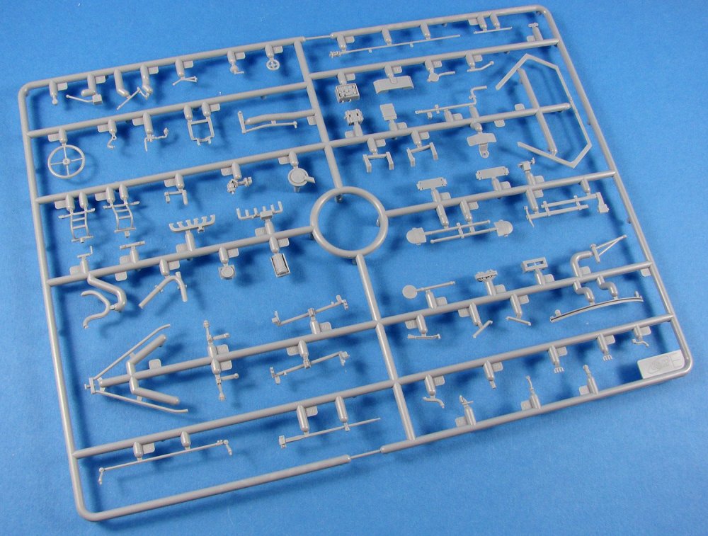
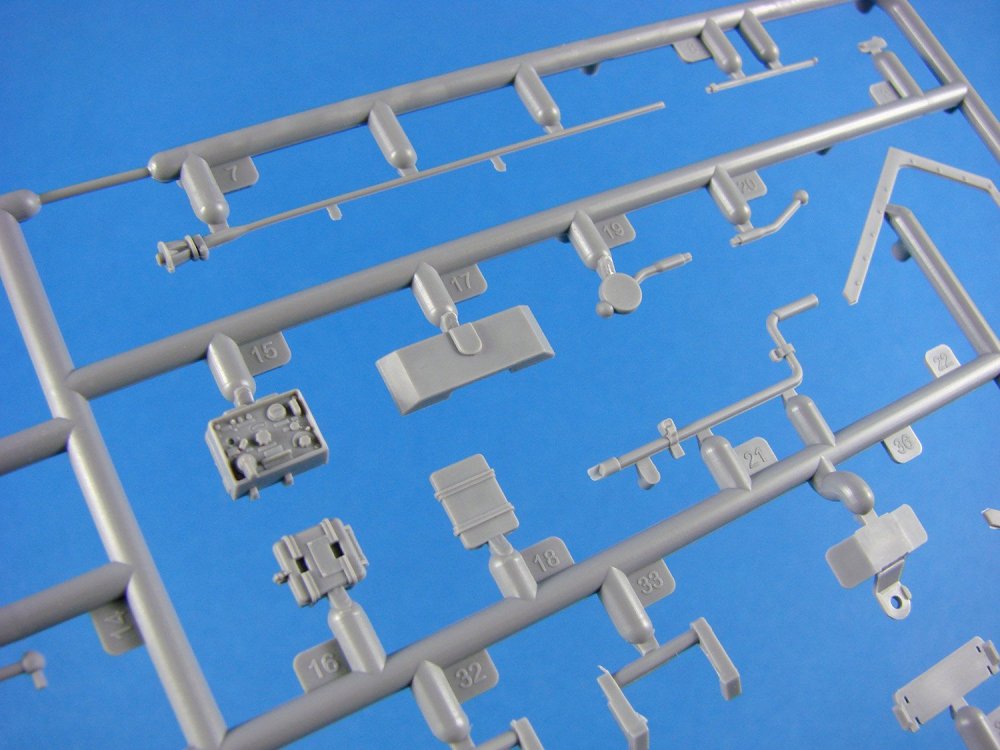
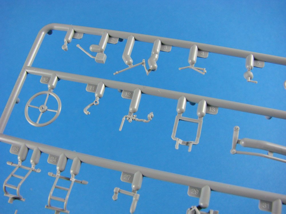
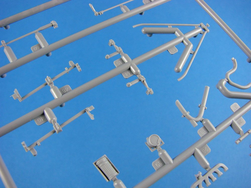
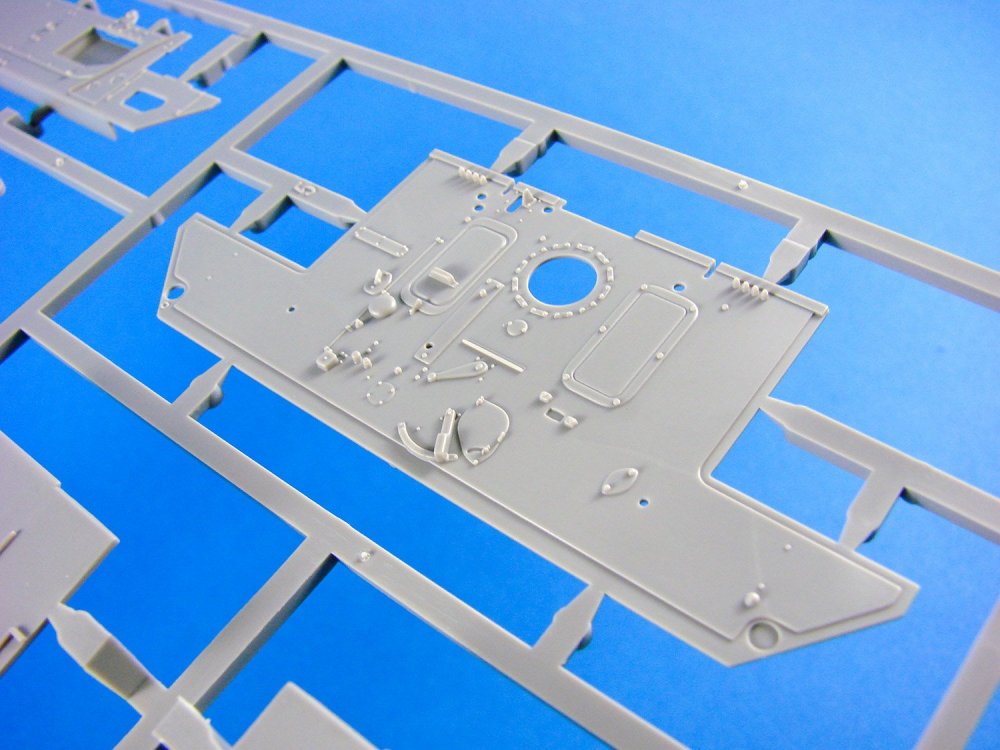
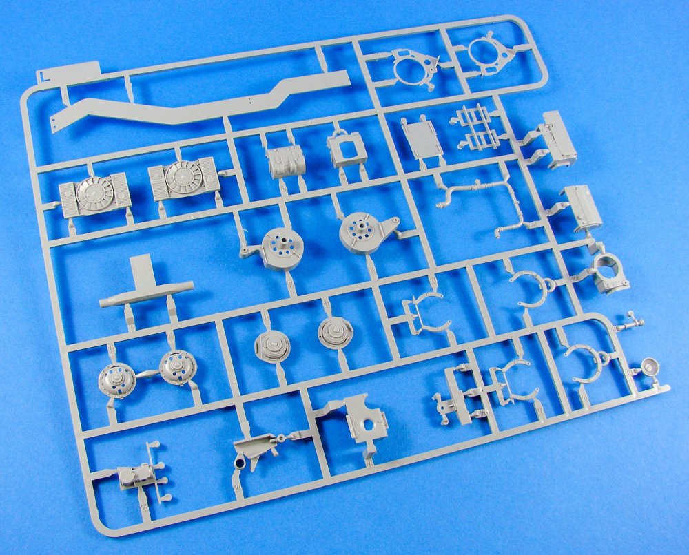
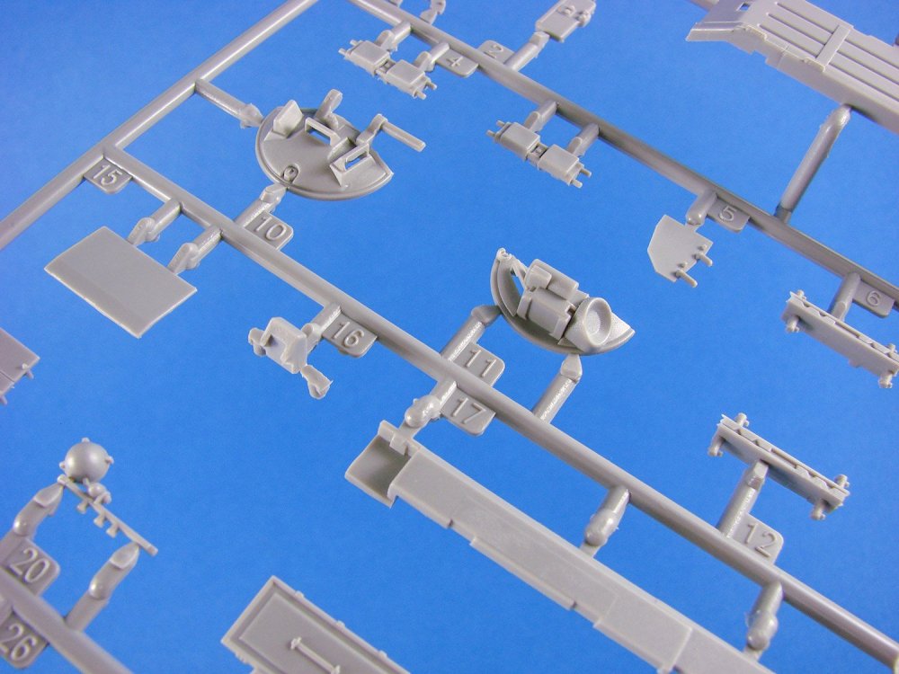
ICM’s presentation is both attractive and robust, with the lid of this box simply being a product identifier, as there is a complete, lidded corrugated box beneath it. Artwork is up to ICM’s usual high standard with an image of the Hanomag on operations in France. Small clear tape tabs hold the lid in position and when these are cut through and removed, the box below is a single-piece affair with a tabbed lid. Inside, there are FIVE light grey styrene sprues packed into a single clear sleeve, one clear sprue individually packed, and a sleeve containing black vinyl parts for the tracks and wheels. A small decal sheet is enclosed, as is the instruction manual, of course.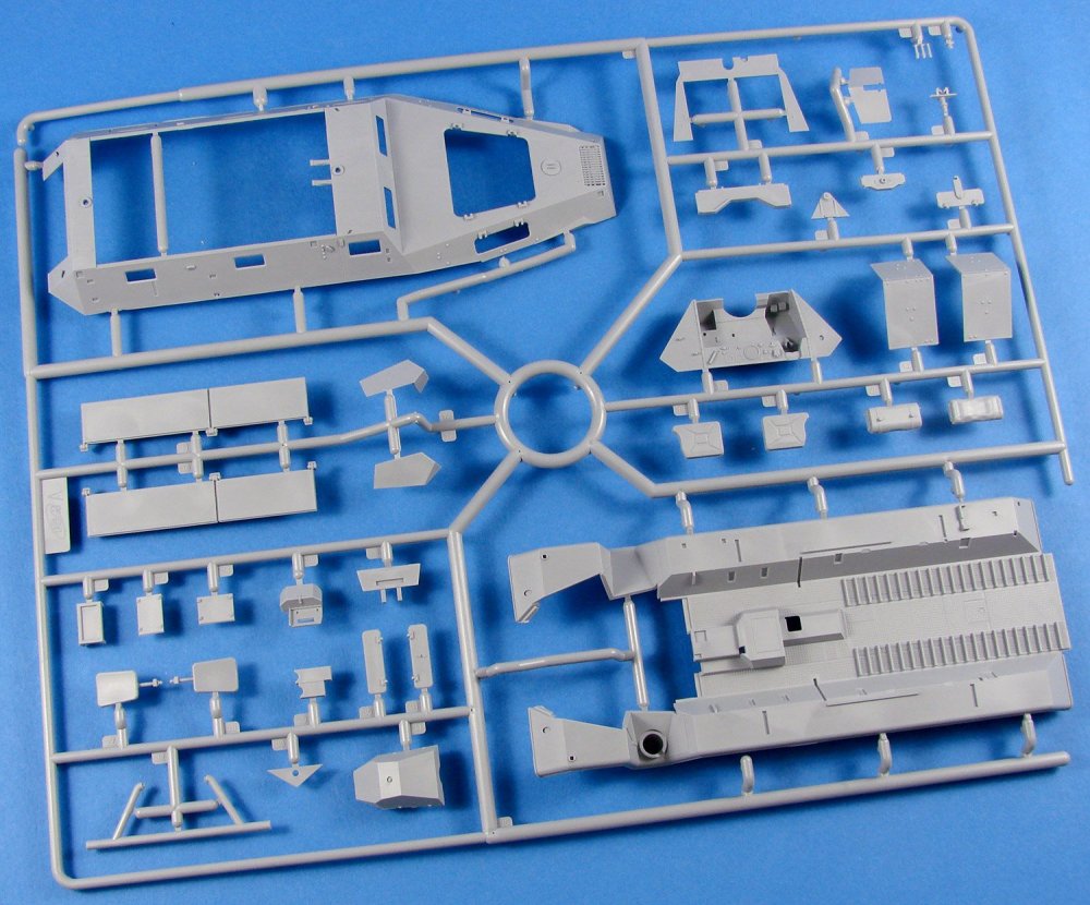


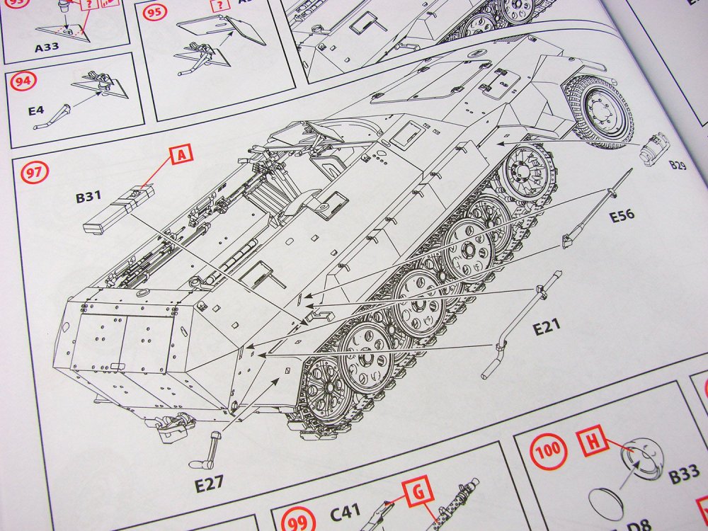
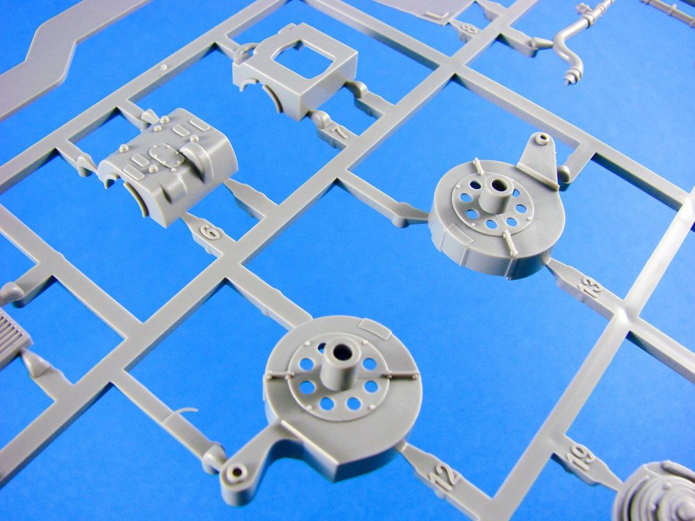
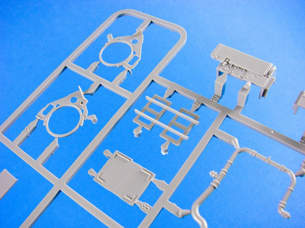
Construction begins with the lower hull plate and its port and bolt details. With the side panels and forward engine bulkhead attached, this assembly is then fitted to a part that comprises the fenders and crew compartment/interior. It does become clear at this stage that this particular model also has the complete interior, including engine. With the fenders loaded out with their stowage boxes, the interior assembly continues with the application of the fighting compartment sidewalls that sit up against the stowage bins, rear bulkhead into which the door will later fit, and armoured engine sump panel etc.


Underneath the Hanomag, a lot of detail has been incorporated into the forward wheels assembly with the leaf-spring suspension bar and axle, plus the drive pinions. A really nice touch here is that the front of the Hanomag has a lower armoured plate with a maintenance panel that can be displayed in an open position, so you can create a detail diorama and show off all the effort within.

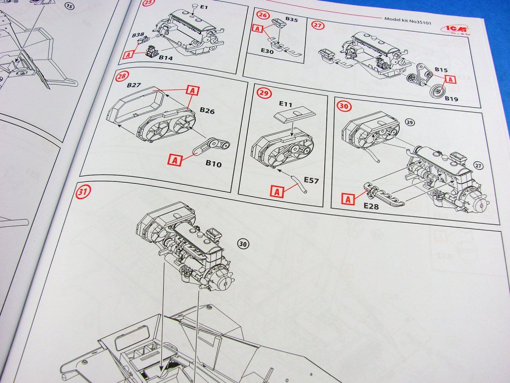
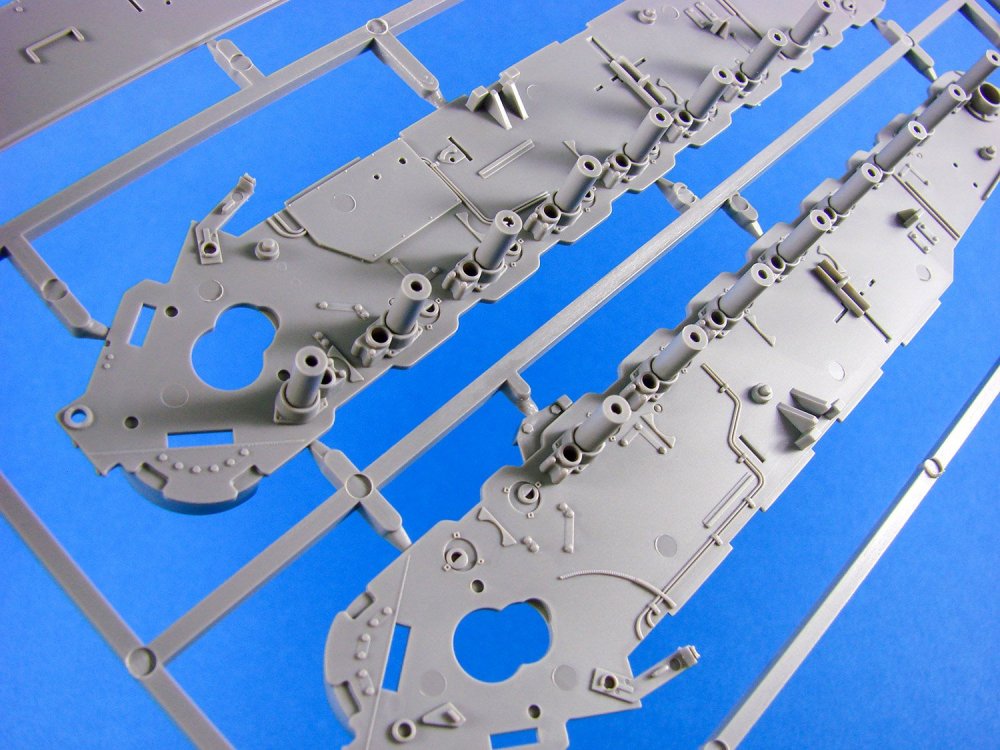
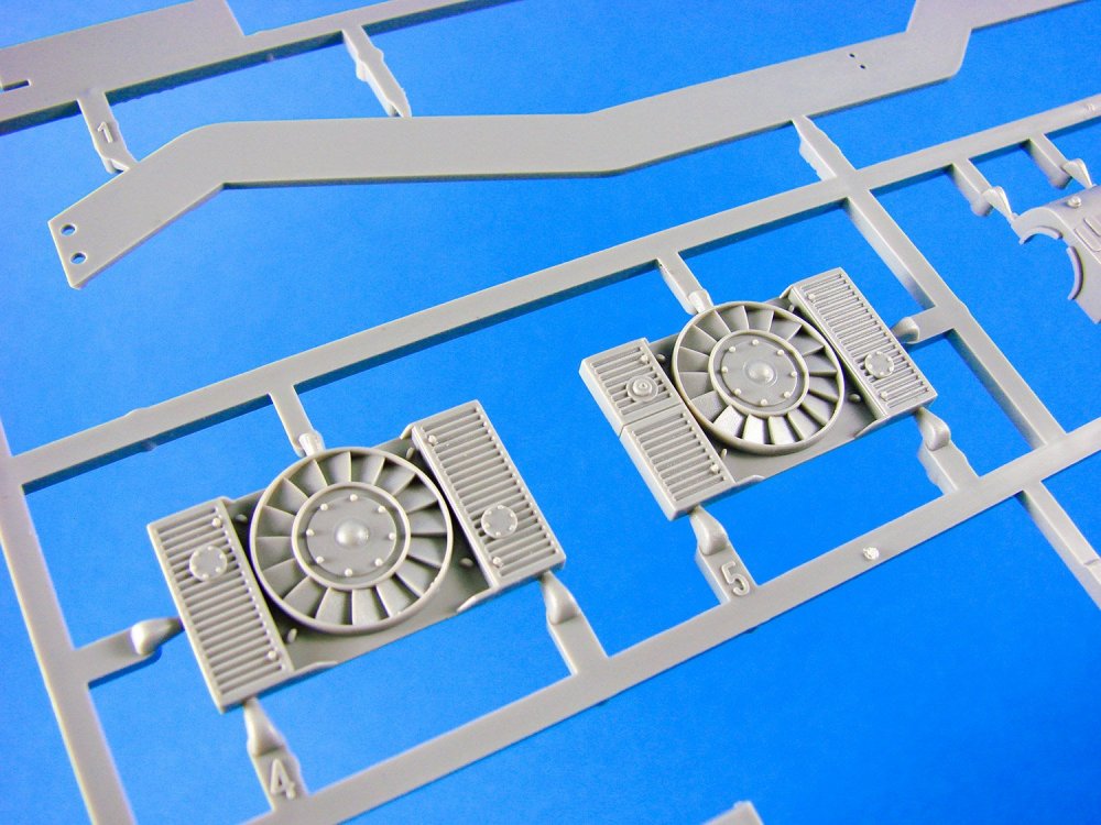
The Maybach HL 42 6-cylinder petrol engine is next to be constructed, comprising of around 20 parts, and this will build up into a more than reasonable reproduction of the real thing, complete with fan belts, authentic crank case and block, magnetos and carburettors, etc.

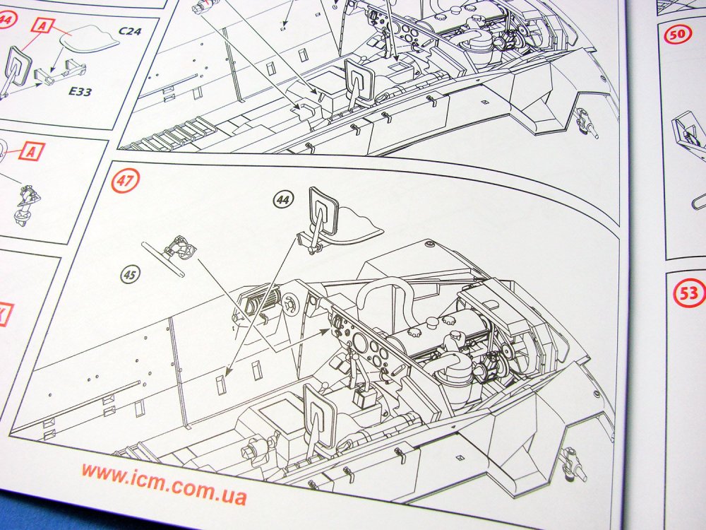
The drivers compartment has a forward bulkhead with blank gauge faces into which the decal instrumentation will affix. The fighting compartment is festooned with equipment such as blankets, ammunition canisters and boxes, weapons, jerrycans etc.


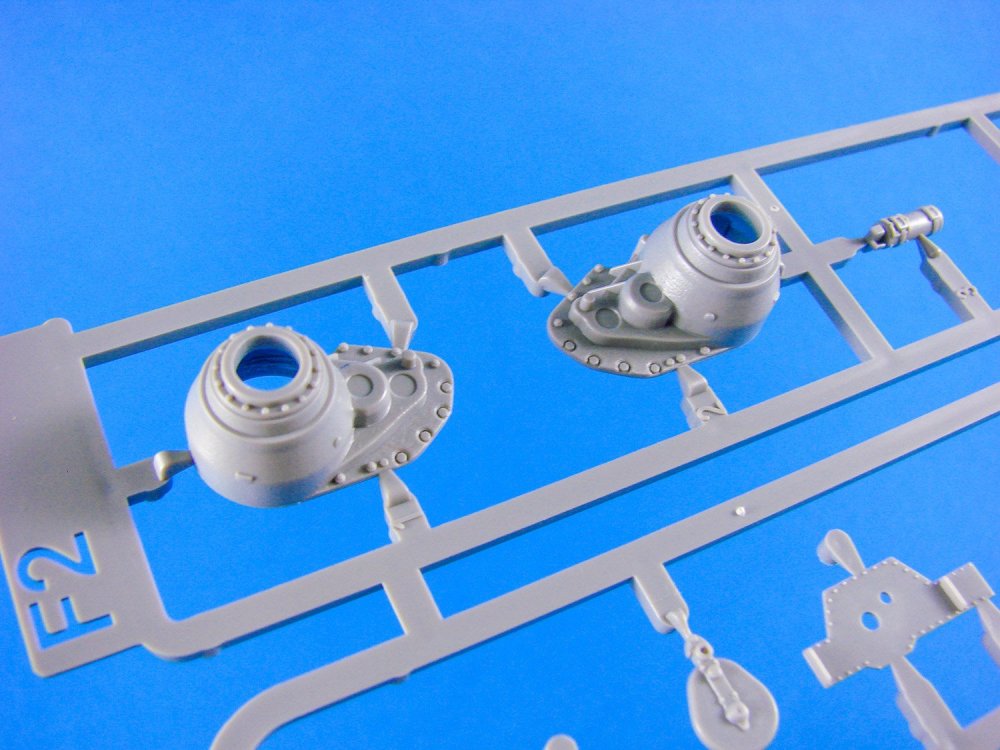
ICM has moulded the upper hull with the various vision ports as separate parts, for both the driver and soldiers in the fighting compartment. Whilst the instructions show these as being closed, it looks easy enough to pose them in a lifted position. The two-piece engine access doors are also separate, as are the engine side panel access positions. Again, a dream for those who wish to finish their model in a diorama, or simply as a study of a vehicle with detailed interior. Internally, the upper hull is also very detailed, with the vision port mechanisms, rifles, battery and radio set etc. The rear doors are provided as separate parts, and although shown closed, I’m pretty sure you could model these in an open position without too much effort.
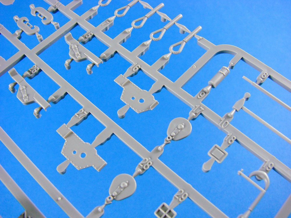
Two identical sprues are supplied for the drive and road wheels, with other parts included for the fighting compartment benches, ammunition, weapons and those vision port mechanisms, but to name a few.
Black vinyl tracks are included, as are the front drive wheels. Like vinyl, or loathe it, these are very nicely moulded and should look very good when fitted. If you hate making up track links, like me, then I’m more than happy with this for a vehicle such as the 251.
Decals
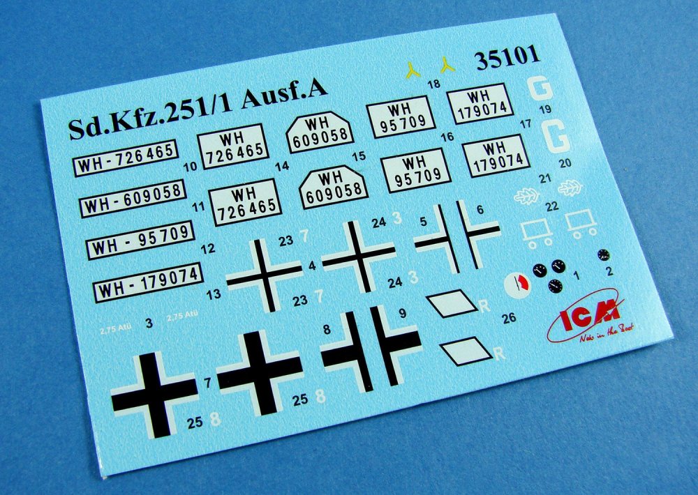
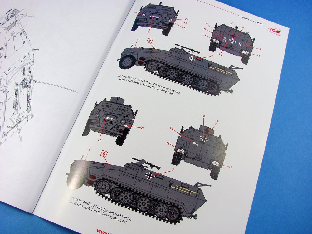
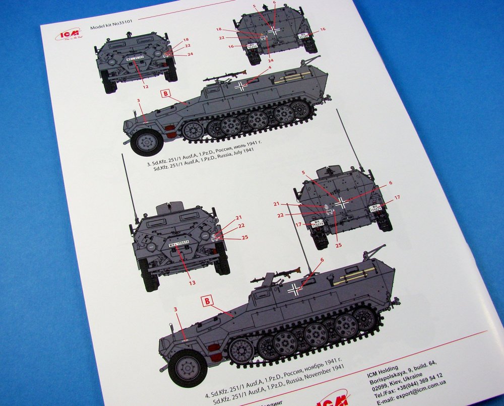
A small sheet contains the various licence plates, national markings and instruments for the driver’s compartment. I think these are printed by ICM too, with everything being suitable thin, with opaque colour, minimal carrier film and perfect registration. The four schemes supplied are:
- Sd.Kfz.251/1 Ausf.A, 1.Pz.D., France, May 1940
- Sd.Kfz.251/1 Ausf.A, 2.Pz.D., Greece, May 1941
- Sd.Kfz.251/1 Ausf.A, 1.Pz.D., Russia, July 1941
- Sd.Kfz.251/1 Ausf.A, 1.Pz.D., Russia, November 1941
Instructions
These are provided by means of a 28-page A4-size manual, with some colour artwork and history printed on the cover. A paint guide is also supplied here for Revell and Tamiya colours. Inside the manual, a parts map is supplied with unused parts shaded out. Construction itself takes place over 103 stages, using clear and uncomplicated line drawings, sans shading. The last two pages contain the four schemes, albeit almost identical except for the licence plates. One machine also has a radio mast fitted.

Conclusion
A superbly detailed model with a very respectful parts count, despite the tracks being vinyl. All areas of the 251 have been faithfully recreated and provide the modeller with many options that a kit from this particular price range would not normally cater to. Whilst I have a Dragon kit in stash, it certainly cost far more than this release, and most definitely a whole lot more. Despite the detail therein, this shouldn’t be tool challenging a project and will prove to be an ideal candidate for armour modellers ranging from newcomer to those who require that little extra. A superb kit!My sincere thanks to ICM for providing this kit for review on Large Scale Modeller.

-
1
-
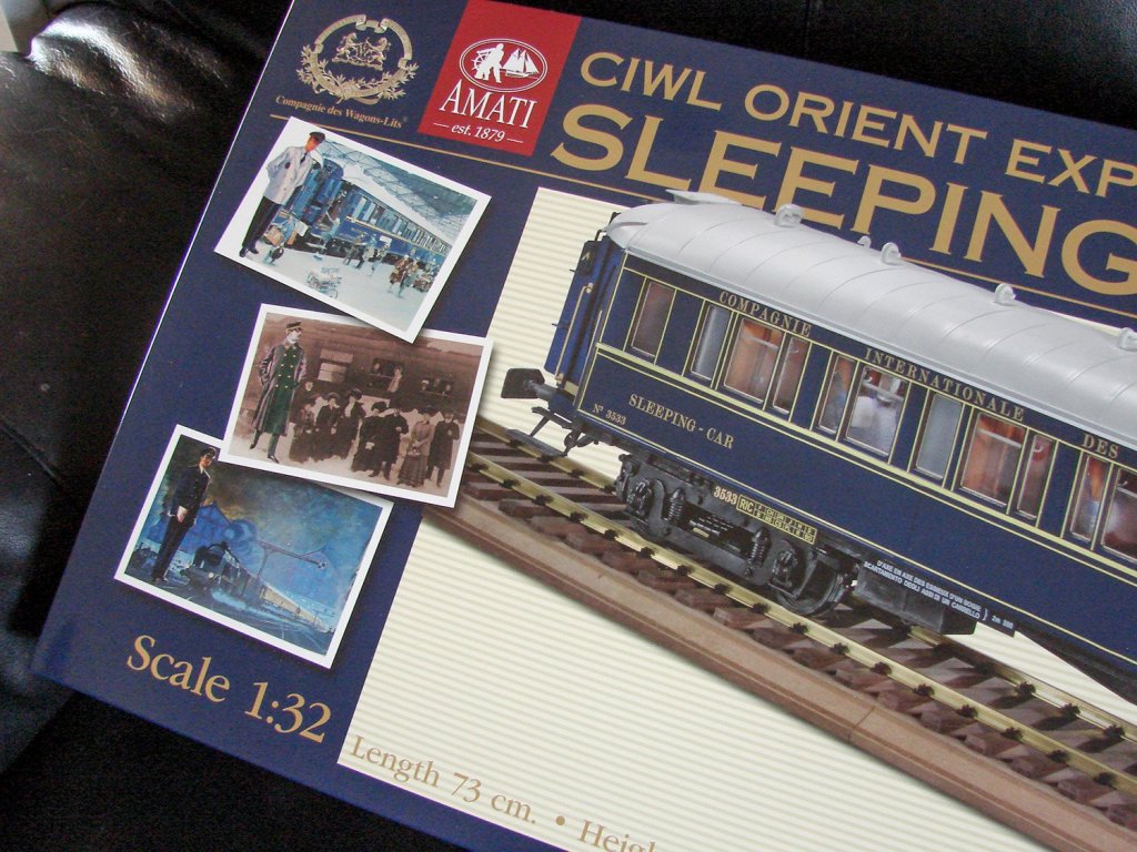
1/32 1929 Orient Express Sleeping Car No.3533 LX
Amati
Catalogue # 1714/01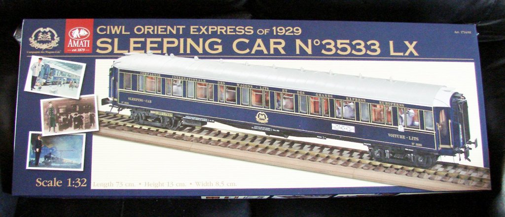
The Orient Expresswas a long-distance passenger train service created in 1883 by Compagnie Internationale des Wagons-Lits (CIWL). The route and rolling stock of the Orient Express changed many times. Several routes in the past concurrently used the Orient Express name, or slight variations. Although the original Orient Express was simply a normal international railway service, the name became synonymous with intrigue and luxury travel. The two city names most prominently associated with the Orient Express are Paris and Constantinople (Istanbul) the original endpoints of the timetabled service. The Orient Express was a showcase of luxury and comfort at a time when travelling was still rough and dangerous. On June 5, 1883, the first Express d'Orient left Paris for Vienna. Vienna remained the terminus until October 4, 1883. The train was officially renamed Orient Express in 1891. In 1889, the train's eastern terminus became Varna in Bulgaria, where passengers could take a ship to Constantinople. On June 1, 1889, the first direct train to Istanbul left Paris (Gare de l'Est). Istanbul remained its easternmost stop until May 19, 1977.
1929 Sleeping Car shown from 4.00minutes (new upholstery)The onset of World War I in 1914 saw Orient Express services suspended. They resumed at the end of hostilities in 1918, and in 1919 the opening of the Simplon Tunnel allowed the introduction of a more southerly route via Milan, Venice, and Trieste. The 1930s saw the Orient Express services at its most popular, with three parallel services running: the Orient Express, the Simplon Orient Express, and also the Arlberg Orient Express, which ran via Zürich and Innsbruck to Budapest, with sleeper cars running onwards from there to Bucharest and Athens. During this time, the Orient Express acquired its reputation for comfort and luxury, carrying sleeping-cars with permanent service and restaurant cars known for the quality of their cuisine. Royalty, nobles, diplomats, business people, and the bourgeoisie in general patronized it. Each of the Orient Express services also incorporated sleeping cars which had run from Calais to Paris, thus extending the service right from one edge of continental Europe to the other.
The kit
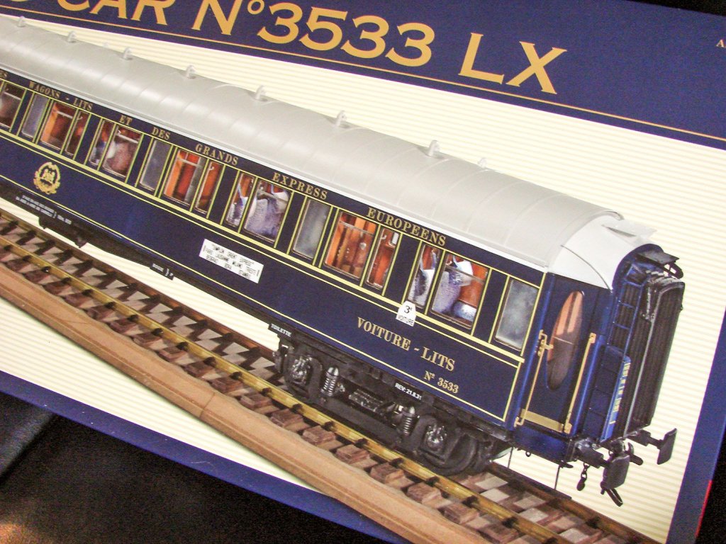
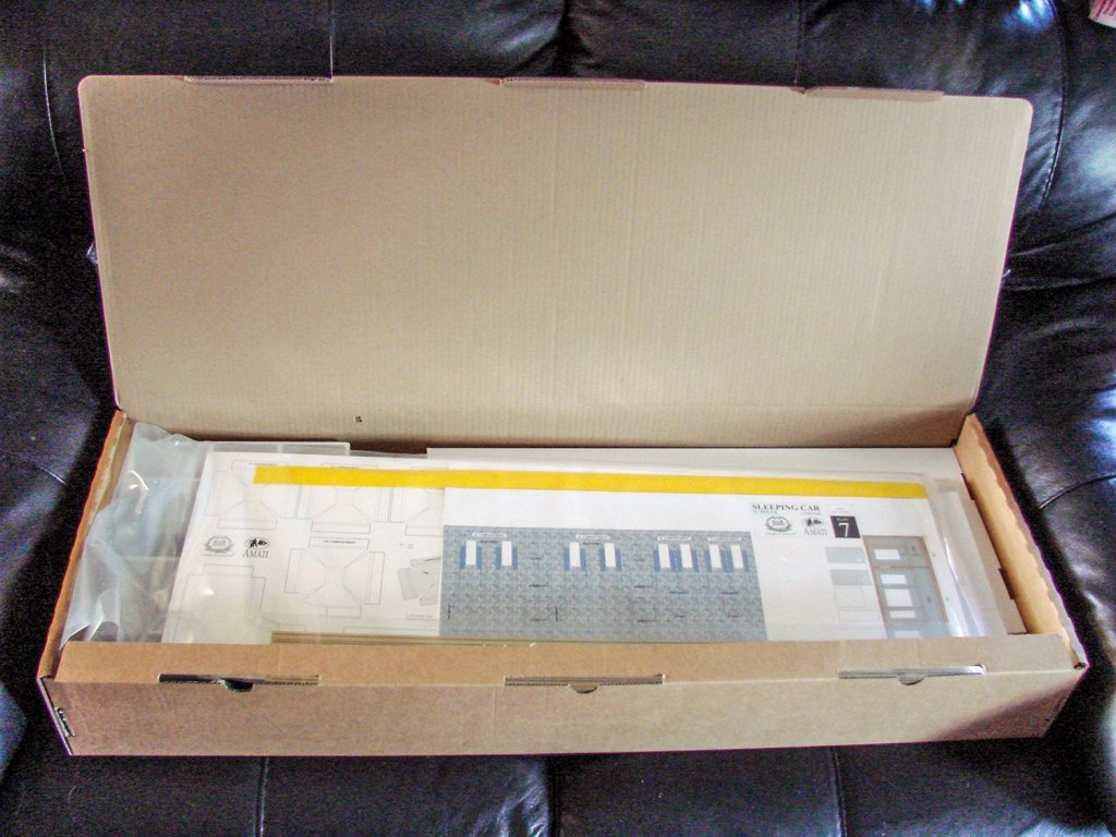

Amati had been publishing videos and photos of this then-upcoming kit on Facebook for a few months, and even though trains aren’t really my thing, this one looked intriguing with its 1920s/30s wooden opulence, so when Amati said they would ship one out to me to look at, that was very exciting. I knew this was going to me one large kit, but I had no idea! The model itself is 1/32 and the box is the same size as their1/72 HMS Vanguardthat I recently took a look at. Whilst the box doesn’t weigh as much as that kit, it’s certainly packed out with some heavy metal. The box lid itself is decorative, depicting the finished model and some period imagery. You will also note that this model has a section of track on which to display the sleeping car. Lifting off that large lid uncovers a complete box with a tabbed, lift up lid, adorned in the Amati logo as standard for these large releases.
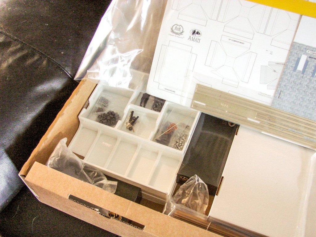
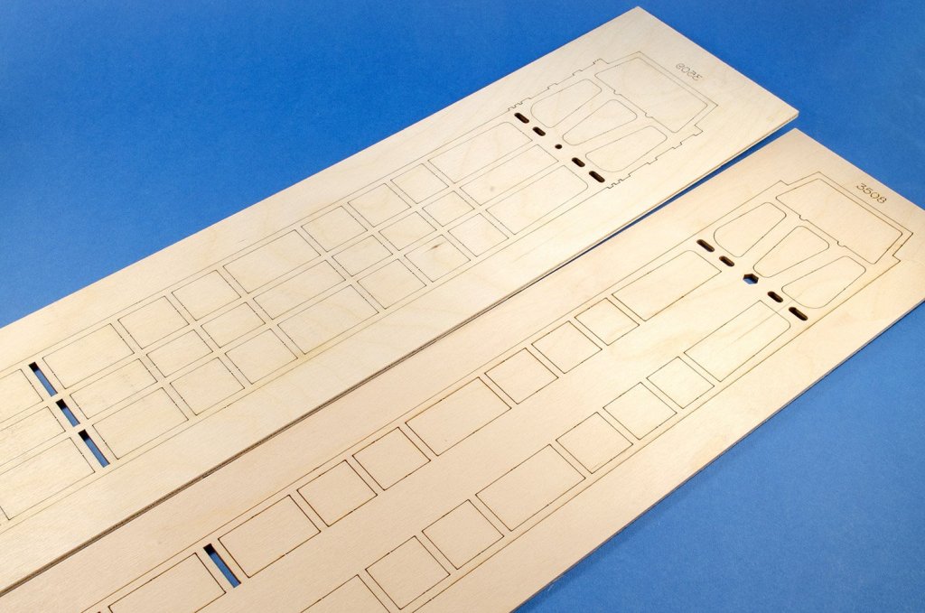
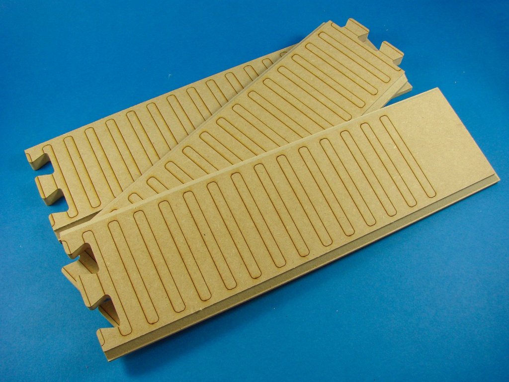
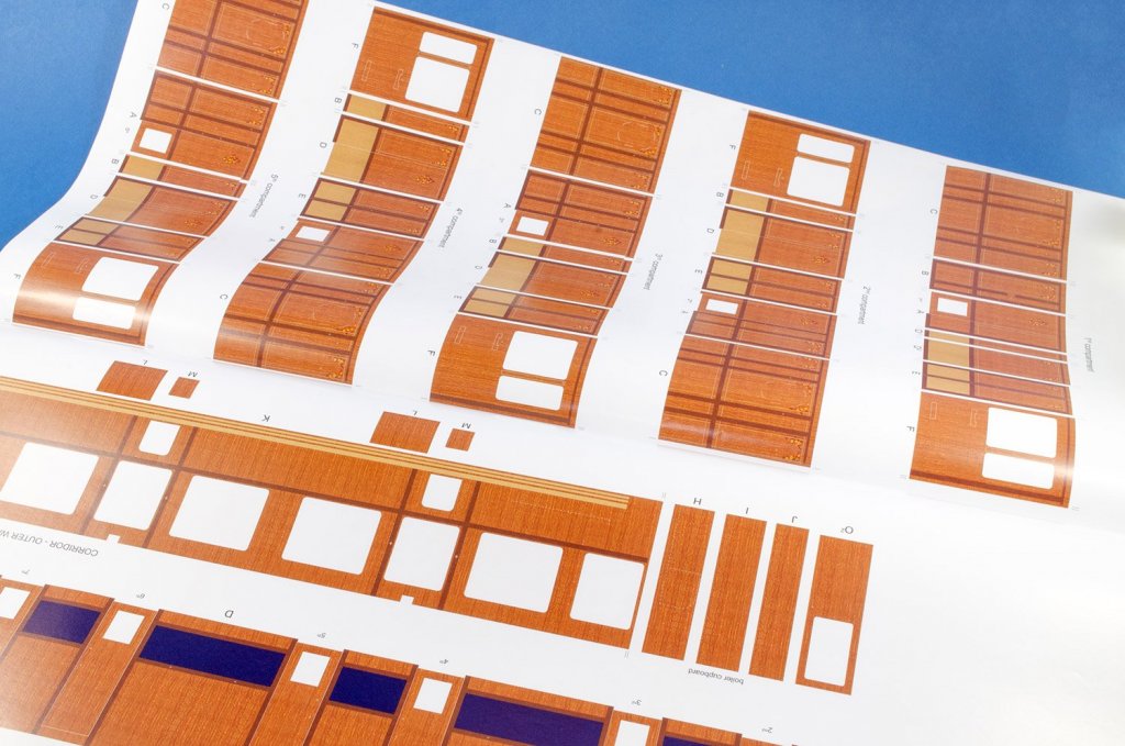
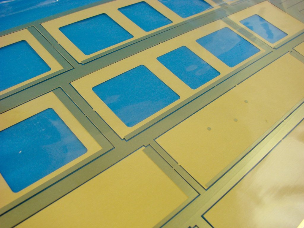
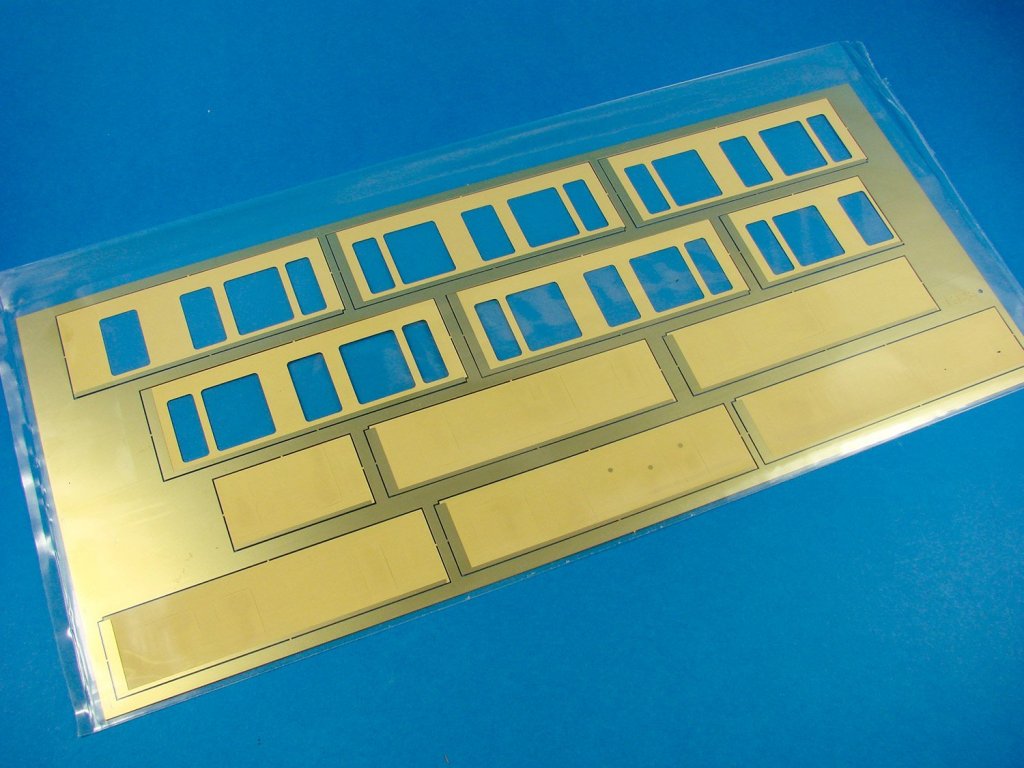
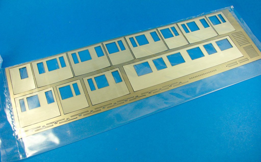
Chassis partsInside the box, we have plastic trays full of parts, two smaller Amati boxes, a large thick plastic sleeve with paper/wood/metal components, and sleeves full of timber strip and brass section strip. There are also a series of folded plans and TWO perfect-bound, full colour instruction books which look sumptuous. Lifting all of these out uncovers two card covers that when removed, show a whole swathe of photo-etch brass and nickel-silver sheets, and a bag holding three sections for the base onto which the rail tracks and sleepers will mount.
Amati’s 1/32 Orient Express Sleeping Car kit consists of:
- 1x gloss card for carriage ceiling mouldings
- 1x decal sheet for carriage signwriting and stencils
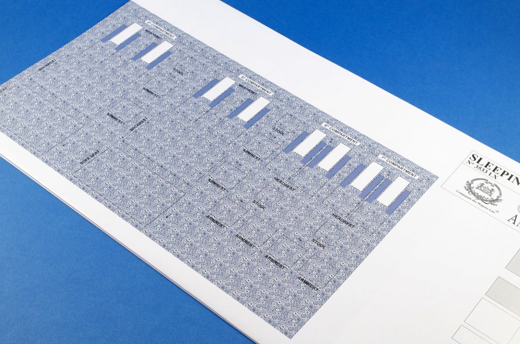
- 2x gloss paper sheets with printed interior wood panelling and carpets. Also contains illustrations of exterior coach work for reference
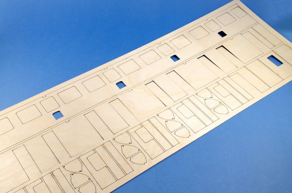
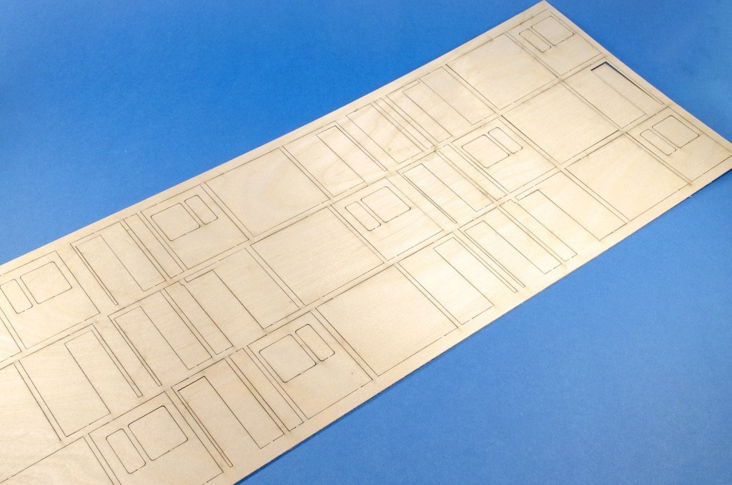
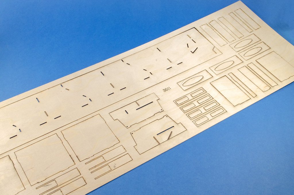
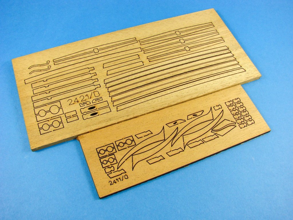
- 2x laser-cut ply sheets for the carriage chassis
- 5x laser-cut ply sheets for all side and internal walls/construction of the carriage.
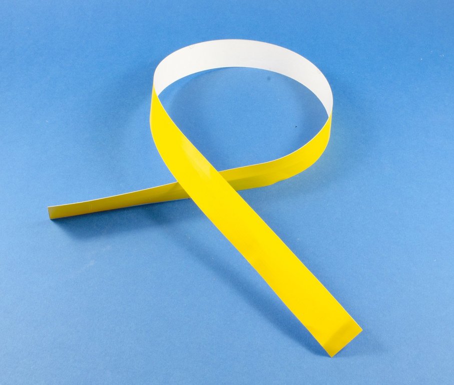
- 1x tape of yellow self-adhesive trim of different widths
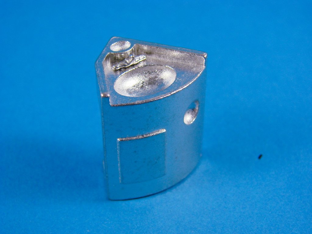
- 2x white trays of cast and turned components, chain and wire. Parts include radiators, tissue dispensers, towel rails, wall mirrors, bottles and holders, soap racks, door handles, coat hooks, locks, eyelets, cabin lights, ventilation panels, electrical sockets, decorative cast exterior crest, spring-leaf shock absorbers, nuts, bolts, boiler, etc.
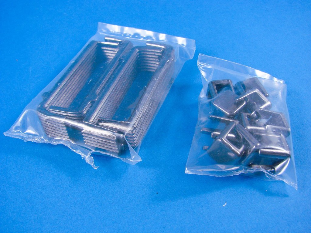
- 2x boxes of components, contains parts such as sofa/bed carcasses and cushions, cores for the armrests and hanging headrests, rolling stock wheels and axles, sink units, stools, carriage entry tunnels, etc.
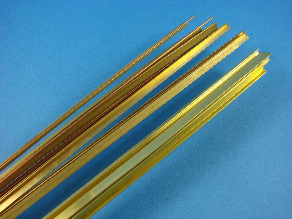
- 1x pack of brass strut sections
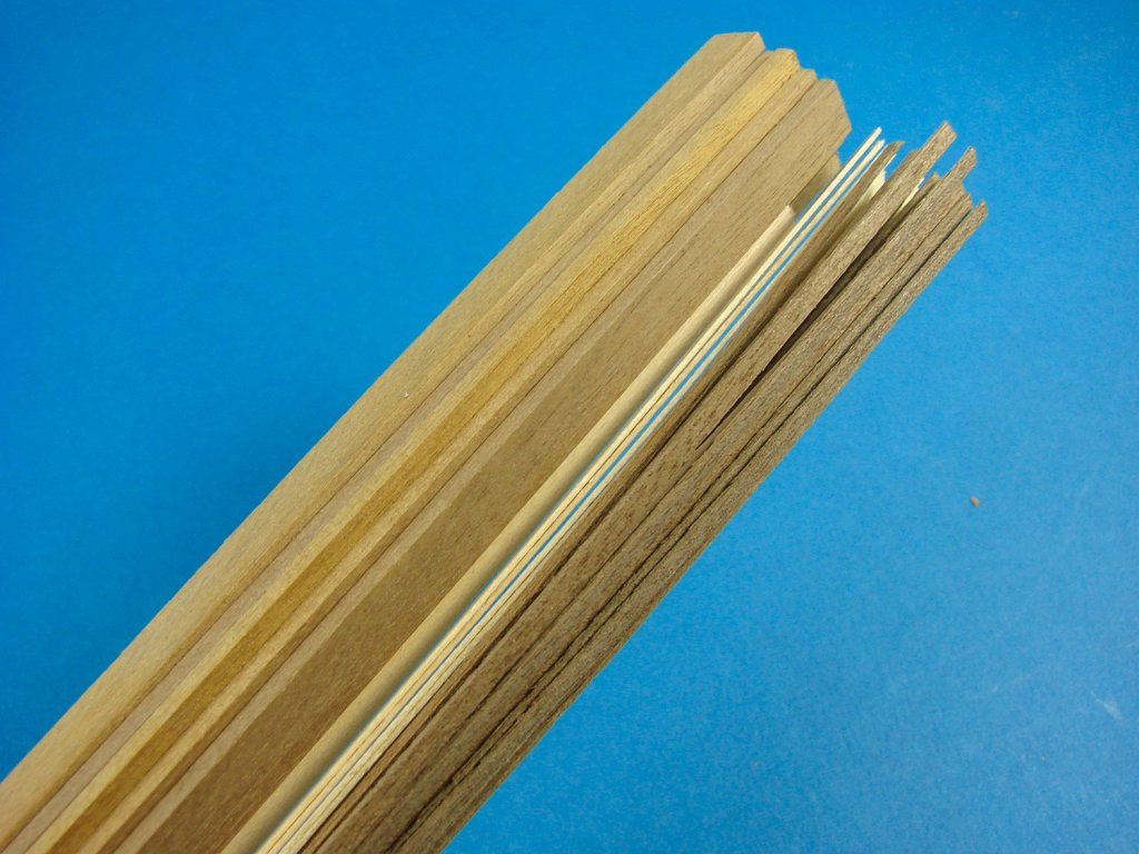
- Various timber lengths of varying size and type
- 3x MDF track base sections and stirrups
- 4x sheets of photo-etch nickel-silver parts (internal main carriage wall panelling and hinges etc)
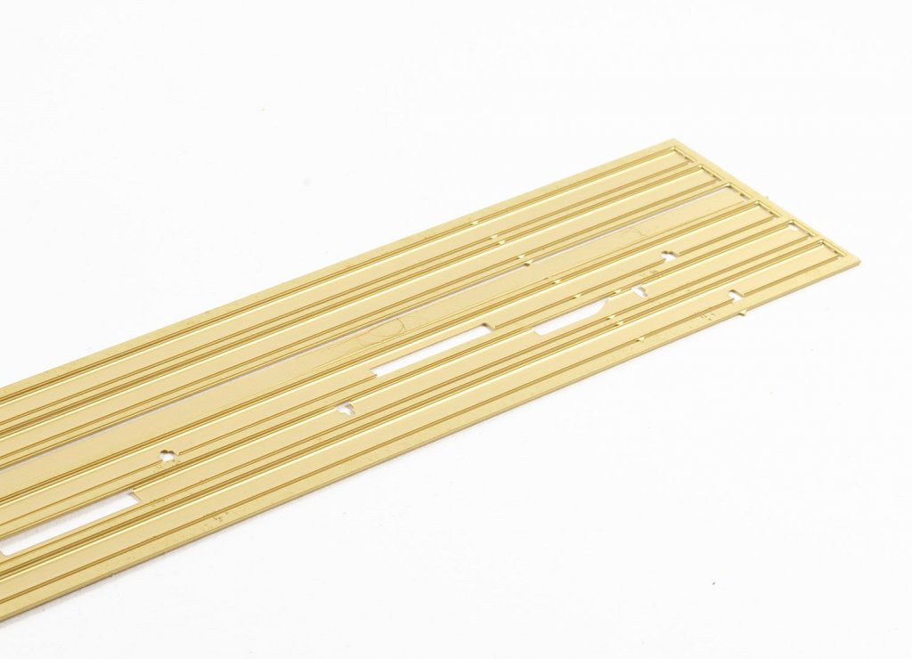
- 17x sheets of photo etch brass parts (chassis, bogies, roof and roof sheathing, exyerior main carriage walls, etc.
- 1x sheet of pre-cut acetate for windows
- 6x parts and plans sheets
-
2x full-colour instruction books
Now, a little about the model itself. Whilst the Orient Express is known for its amazingly high standards, these sleeping cars only had a single WC for the whole carriage. Amati has created an entire, accurate interior to this model kit, of which the toilet and small boiler closet are also included. To be able to see all of these details, the lid, constructed from photo-etch and rolled brass, is removeable.

White card inserts for she shaped interior ceilings are included, and this would provide an amazing opportunity to add some soft lighting which would set off each of the cabins. Each of those cabins is intricately detailed, and whilst have no per-cabin toilet facilities, each cabin does have facilities for passenger ablutions. These come in a stylish curved-door unit which contains sink and other things which you’d expect to see in this area, all intricately reproduced in this kit. The walls of the cabins are wooden panelled, and all of the cabin creature comforts are present, including seats, cushions for arms and head etc, and ceiling racks for storing luggage. Remember, these cabins were pretty compact as passengers spent the day in other areas of the train too. An access corridor runs alongside the cabins, and of course, these are fitted out with radiators etc. In all, an impressive piece of rail history that Amati has gone to pains to recreate here.

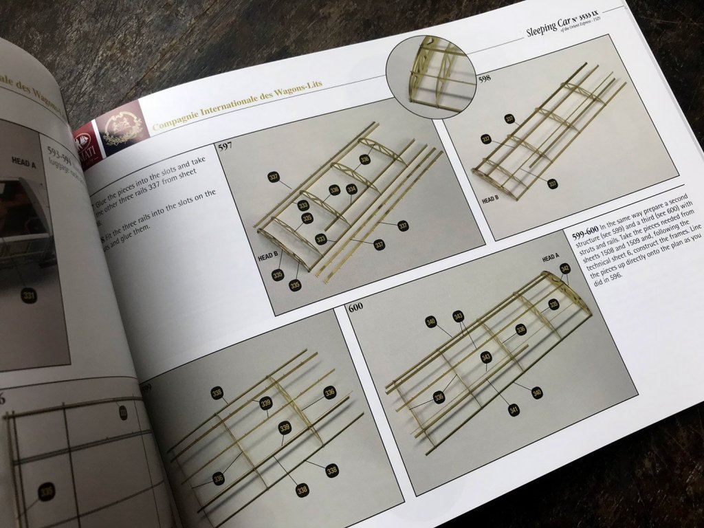
The sleeping car is based on two lengths of laser-cut timber which sit atop each other to produce the main frame of the carriage. On the real thing, this would of course have been metal, so bear that in mind when building and ensure you seal any timber and rub down before filling, priming and painting in black. Added to the metal framework are lengths of heavy-gauge photo etch that create the authentic appearance of the carriage chassis. Other plates etc. are fitted out with miniature nuts and bolts. Brass section strips are also fitted to the entire length of the exterior frame, adding authenticity and some rigidity to the model. There is also a main bolt towards both front and rear of the carriage, onto which the moveable, wheeled bogies will mount. After all, your train won’t just roll in a straight line!


The underside of the sleeping car is incredibly complex with some superbly engineered and cast leaf-spring suspension for the buffers, couplings, photo-etch battery housings, compressed air tank, etc. Assembling the rolling stock/bogies themselves is broken down into over EIGHTY separate stages in around 20 pages of the first construction manual. Of course, all of the parts for this are manufactured from either photo-etch, cast or turned parts, and a photo-etch bending tool really should be mandatory if you wish to tackle this model. After all, if you are willing to shell out 890€ for a kit, then it’s foolhardy not to progress with the required tools.


For the base, Amati has supplied three parts on dovetailed MDF which is profiled for display purposes. The positions of the sleepers is also engraved onto the top. I have to say that the fit of these is so precise that virtually no joint can be seen when they are put together. If you flip them over, you’ll note that there is a pencil mark to show you which part is the best match. Two MDF splints are then to be glued into the underside channels. Now, I don’t think that MDF is a strange material for the base, as you may wish to paint this, but one omission, for me, is any material that can be used to infill between the buffers, such as the gravel/stones. This would have been a nice addition so as to hide the MDF.

The tracks themselves are supplied as brass sections which need to be cut to length. As per the real thing, the tracks are attached to the sleepers by the correct hardware. I would use an assembled wheel/axle section to properly ensure that the tracks are equidistant at both ends, as well as traditional measuring. I would also look at either painting the tracks in an iron colour, or if you can immerse them in a shallow bath of burnishing fluid, then that would also fit the mark.


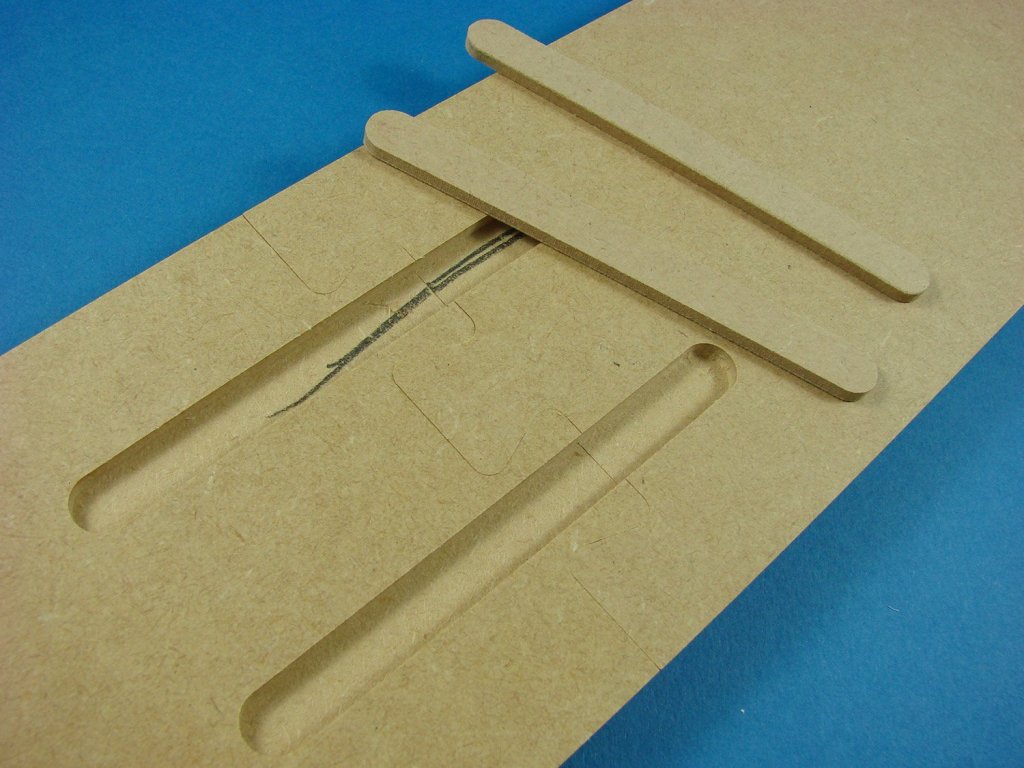
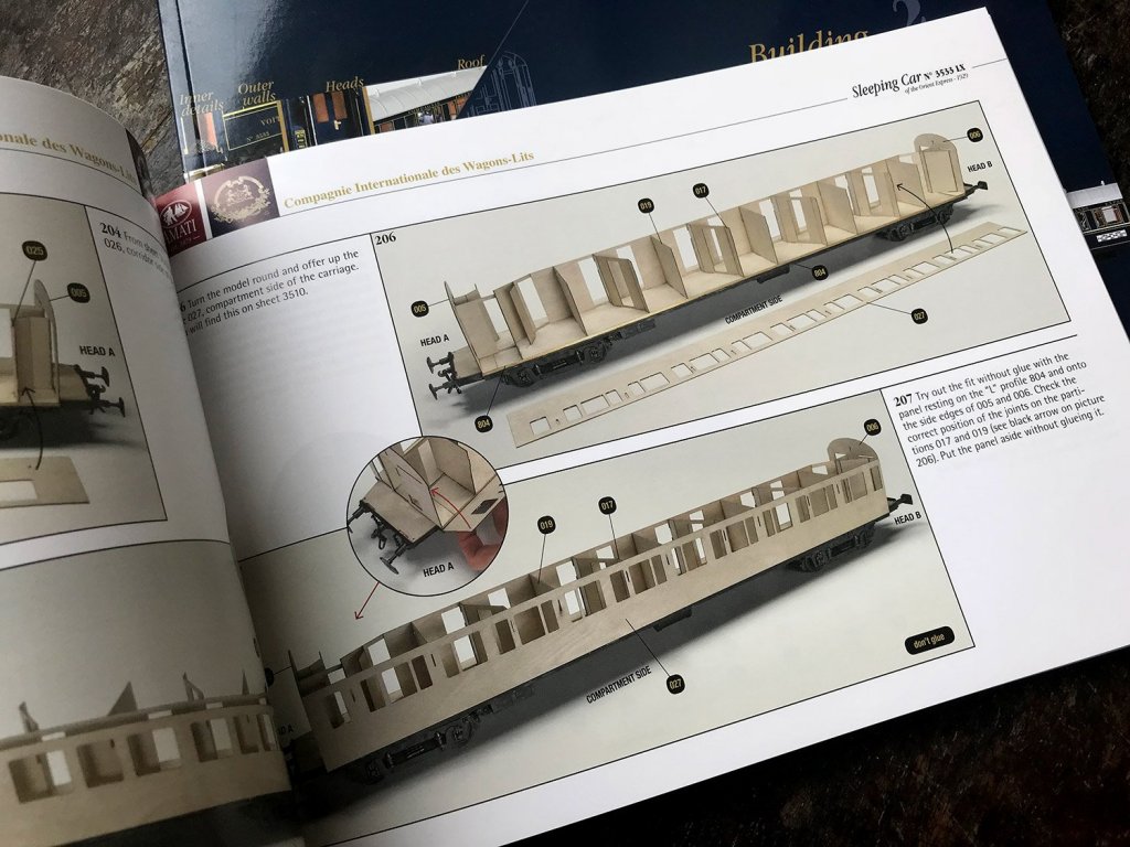
With the base of the model now built, the time has come to assemble the carriage itself. This initially starts with the Head A and Head B bulkheads, followed by the fitting of the interior corridor wall. Onto this are fitted the interior compartment walls, creating the cabins. Please note that a lot of paper cutting will be required as the internal walls in their antique finishes, are printed matter and will need to be fixed to the pre-sealed internal plywood walls. This will also be enhanced with actual timber framing too. The printing of the wooden walls is very, very nice and should look as good as trying to emulate this using precious timbers.
Besides, this approach means we all stand a level chance of success. Actual timber will be used to line the panels, adding to the realism. The carpets are also to be cut from paper. You will need to pick up some paper-crafting skills too as the numerous head rest and arm rest cores, sofa/bed chassis and stools, will need to be wrapped in the same matching paper and neatly fashioned around corners. There are some good techniques to be found online, such as dampening the paper to make it easier to mould around corners etc.


Each cabin will also have its own wash locker, and these are constructed separately and then installed. As well as having all the mod-cons, for the 1920s, the doors on these will actually hinge open and closed. You won’t have this option for the cabin doors though, but these can be posed in any position using the nickel-silver etched parts. The main carriage exterior walls are sheathed in photo-etch brass which will be painted, and the trim/decals added. Internally, those same walls are plated with the nickel-silver panels. I don’t know the reasons for change in material from brass, but the panels are superbly produced. Remember, there’s no actual silver in those parts. Instead, it’s an alloy of zinc, copper and nickel.


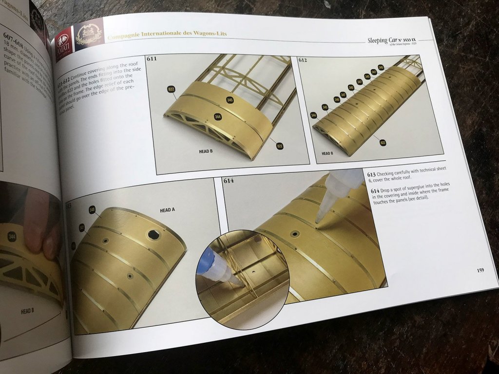
To construct the carriage’s roof, a series of photo-etch frames are interlinked with longerons that have raised pips. Once the basic frame is assembled, a series of individual brass panels are then rolled into shape and the holes in these used to lock over the raised pips of the longerons. Whilst you can use CA generally, I would suggest that the pip areas are soldered and filled before then being filed back flush to the roof. The roof is then painted white. Internally, the card mouldings are then shaped and sealed/sprayed white before decorative wooden edging is applied.
Instruction manuals
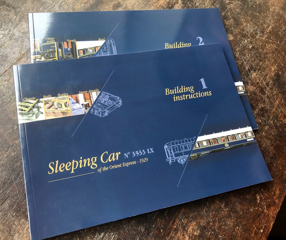
Two full-colour instruction manuals are included, showing the various stages using photographic images and clear text in English, with Italian also. Each step is very easy to understand, in the way that magazine part-works are designed to be straightforward. There’s nothing here that should catch any modeller out, meaning that the only thing you need to have some experience with is photo-etch. Each manual is landscape in format, and perfect-bound, as a novel would be etc. Paint references are used where necessary and supplied in FS codes.


Plans
A number of these sheets are simply for helping the user to identify the various PE parts and wood parts, with a couple of others showing the rail carriage in various plan formats. All line drawings are clear to understand shouldn’t provide the modeller with any issue.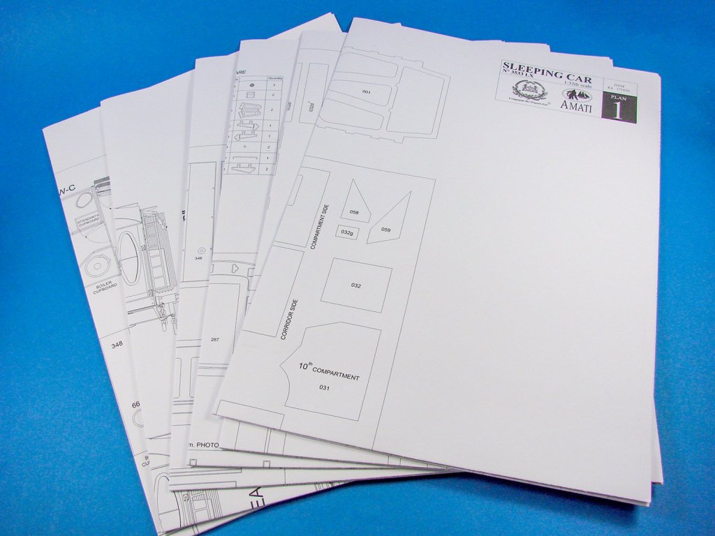
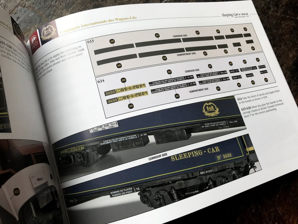
Decals
A single sheet of waterslide decals is included for the exterior livery signwriting etc. Print quality looks excellent. It could be worthwhile trimming any of the clear carrier film as close to the actual decal as required.
Conclusion
This isn’t a cheap kit by any stretch of the imagination, but it is an epic one in every sense. The Orient Express kit is a sort of crossover between vehicle and doll’s house building, with some beautiful period features in the mix. It’s certainly a project that will command a lot of time from you in order to achieve the very best outcome. You really do have to be reasonably adept with photo-etch metal in bending, curving and folding, and although you don’t strictly need to, some elements would be better soldered than glued. A lot of attention to detail has been made here, from the kit detail itself, down to little things like the cut-out paper décor not lying across folds in the sheet paper. The instruction manuals are also a work of art and should be a cinch to follow. Projects like this are usually once in a lifetime, so if you fancy doing something pretty unusual, then this has certainly got to be a major contender. These kits are hot off the press, only having being released within the last 2 weeks, so get them whilst their fresh!My sincere thanks to Amati for sending this kit out for review on Large Scale Modeller. To purchase, check your favourite Amati shop or online retailer. Tell them you saw the review here on LSM.

-
1
-
Such a great looking plane. Nice review too. Looks a keeper.
-
2
-
-
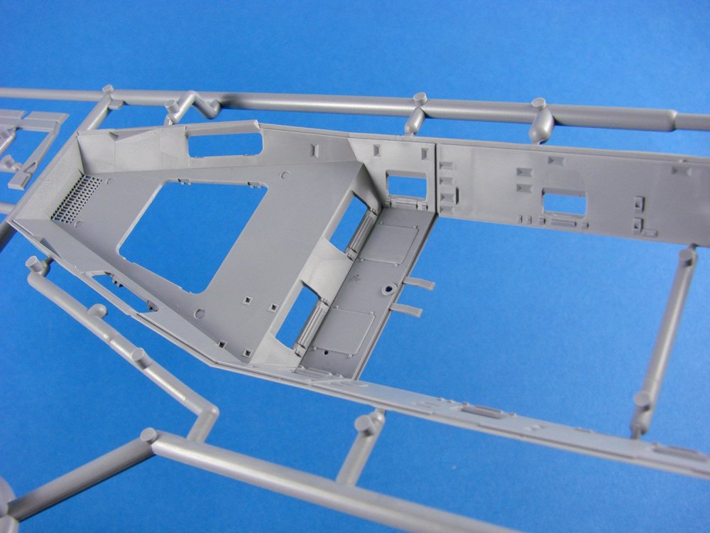
1:35 Bergepanther Ausf.A – Assembled by Demag
Takom
Catalogue # 2101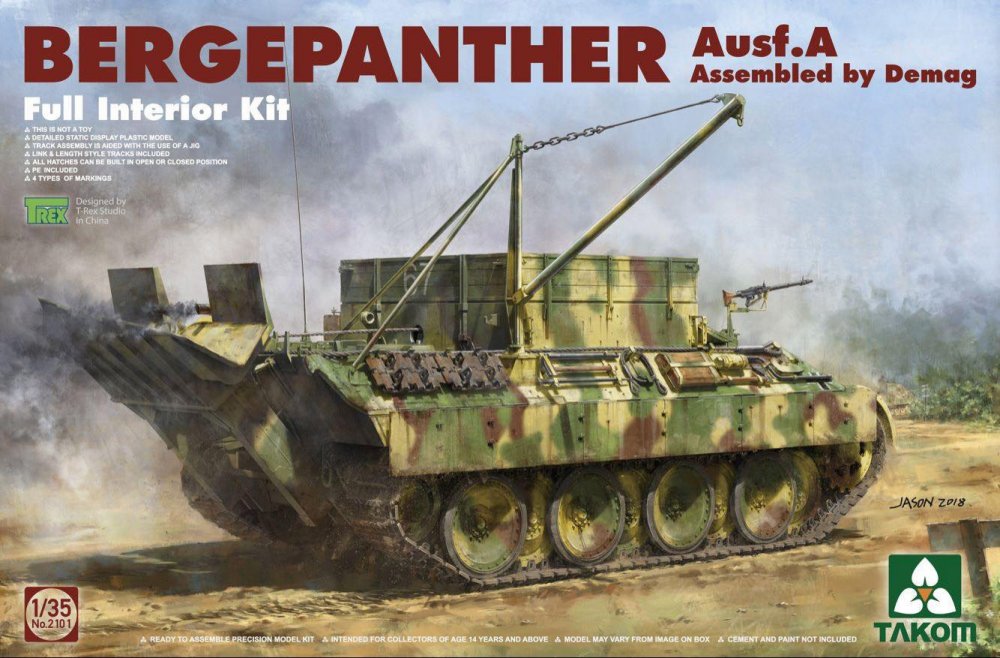
The Bergepanther was an armoured recovery vehicle version of the "Panther" (Sd.Kfz. 179), often referred to only as "Bergepanther". The idea of a modified Panther emerged in 1943, due to problems in the recovery of heavy and medium tanks. The half-track vehicles previously used for salvaging, were rarely able to successfully recover a Panther or Tiger. Using another Tiger or Panther as a tow vehicle was also strictly prohibited, as this could result in the loss of both tanks.
The first Bergepanther to be completed was based on the Panther Ausf. D, in which the turret was left off by the manufacturer (MAN). Henschel, Daimler-Benz and Demag (Deutsche Maschinenbau-Aktiengesellschaft) eventually took on Bergepanther production. The crew consisted of at least three soldiers, with two of those operating the newly installed salvage apparatus. Where the turret was originally installed, was now a square wooden and metal structure which sat atop the new internal winch, with a 40-ton tow capability. A large sponson fitted to the stern, served as support. The Bergepanther was quite reliable and could be used even under enemy fire because of its armour protection. From 1943 to 1945, about 339 Bergepanther all types were built by MAN, Henschel, Daimler-Benz (Factory Berlin-Marienfelde) and Demag.
Adapted from Wikipedia.de
The kit
With the abundance of Panther kits that seem to have swamped the market this year, I somehow get the feeling that the turretless Bergepanther is what many modellers have reallywanted to see. Whilst we have indeed had the Bergepanther in 1:35 before, from ICM/Revell, and Italeri, these kits stretch back in origin between 13 and 25 years respectively. A modern tooling of this is what was seriously needed, so I can indeed understand the excitement in the armour-modelling community. This kit is based on the 2018 tooling of Takom’s amazing Panther kit releases (check out our LSM Pilot build HERE), and even better, Takom has just released this in both Ausf.A and Ausf.D flavours. Today I’ll be looking at the Ausf.A version. We have also been sent the other kit which will be reviewed in the very near future by Jeroen Peters.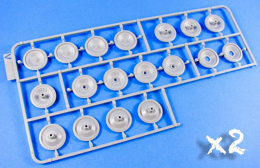


Takom seem to be the masters of very cool box art when it comes to armour kits. This one shows a sort of rear, three-quarter view of this unusual vehicle, obviously chosen as you can see all the general modifications from that angle. Even without the turret and interior, this kit packs a serious plastic punch with its new winch and wooden upper hull structures, etc. In fact, opening that lid will prove what a task it will be to get all of the styrene back in the box, once removed. It took three attempts for me after completing my photography.


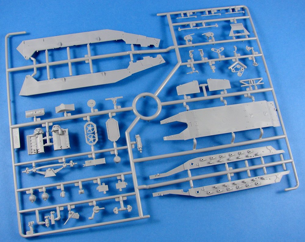
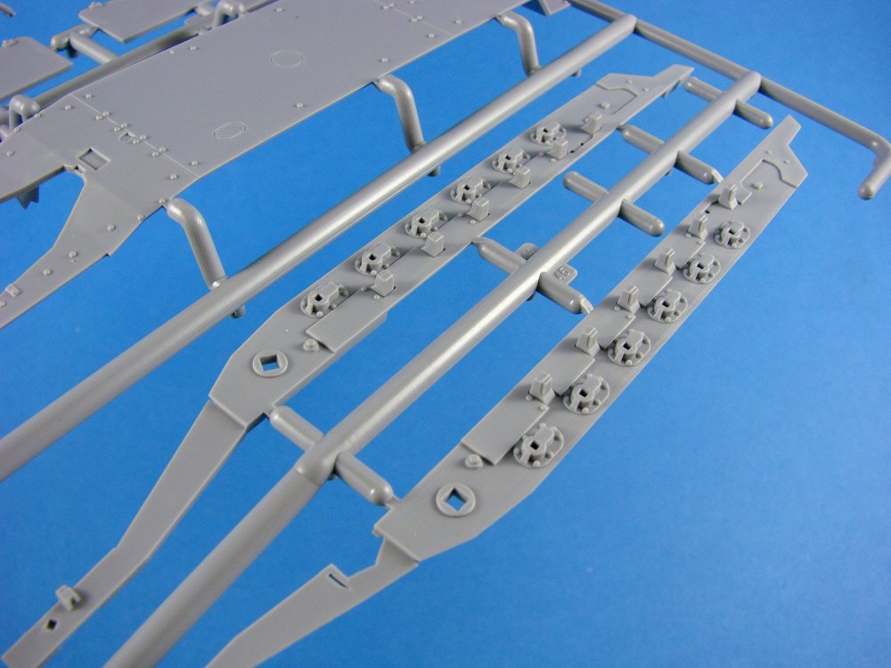
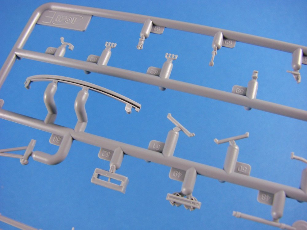
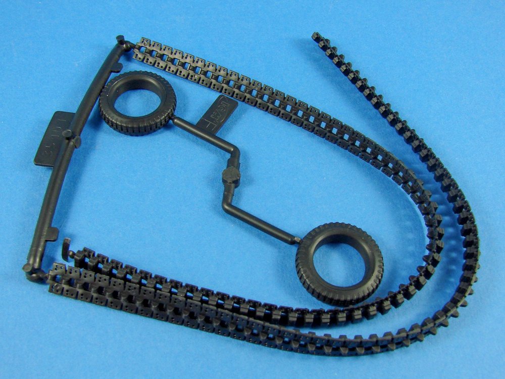
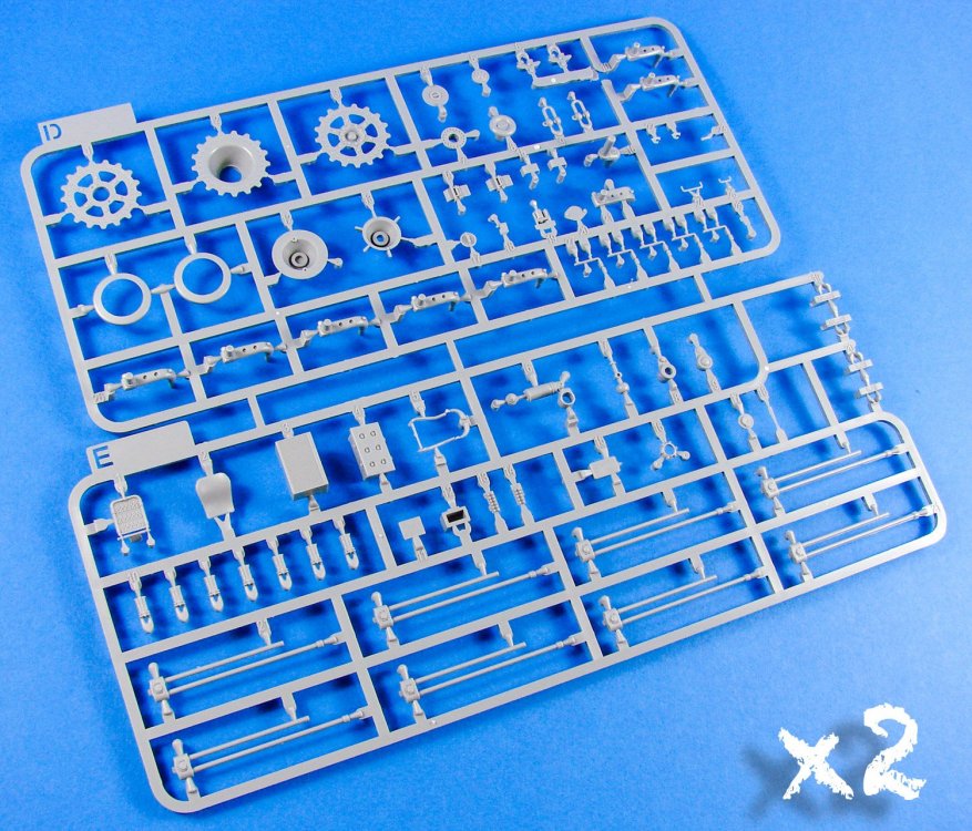
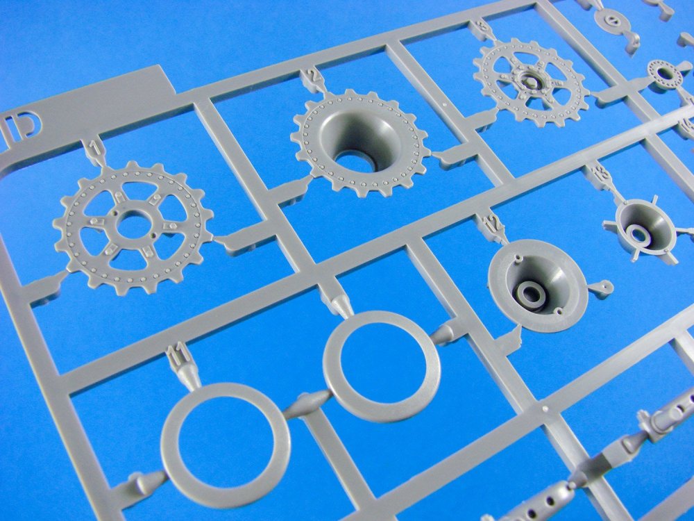
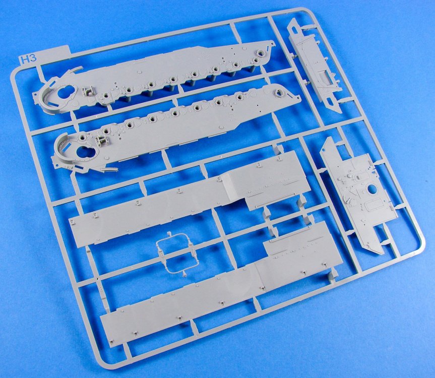
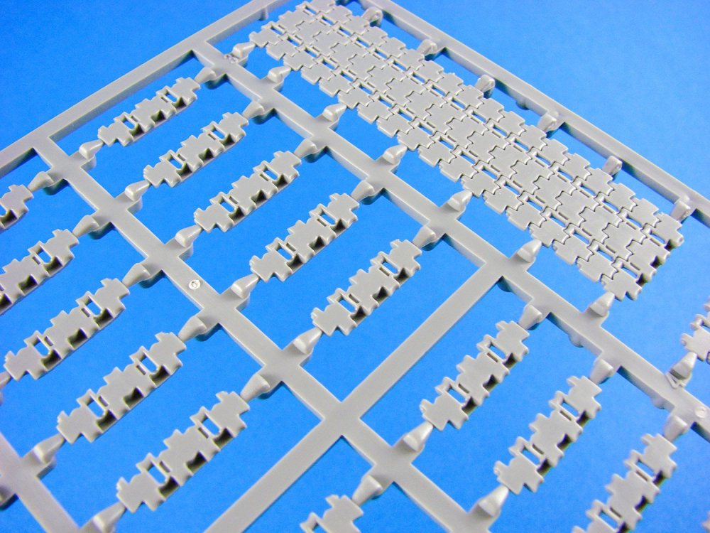
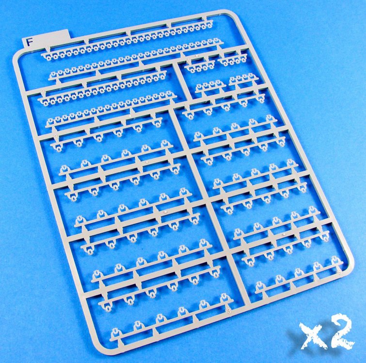
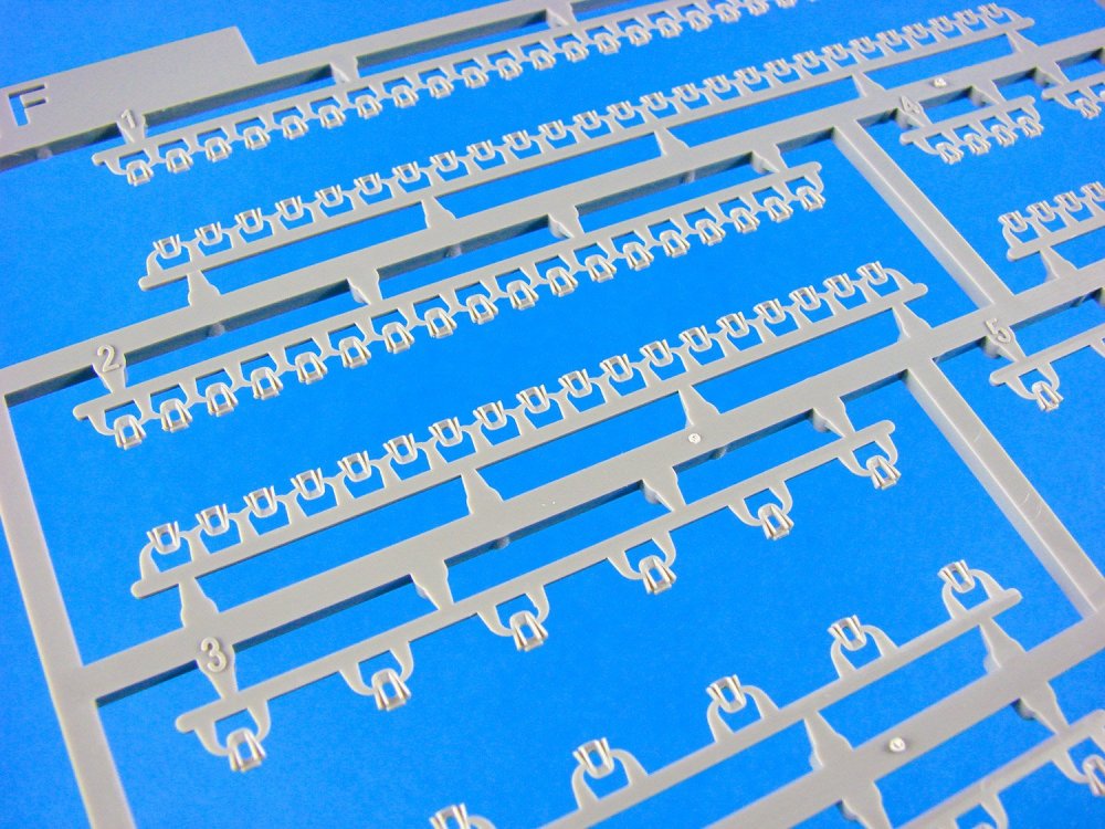
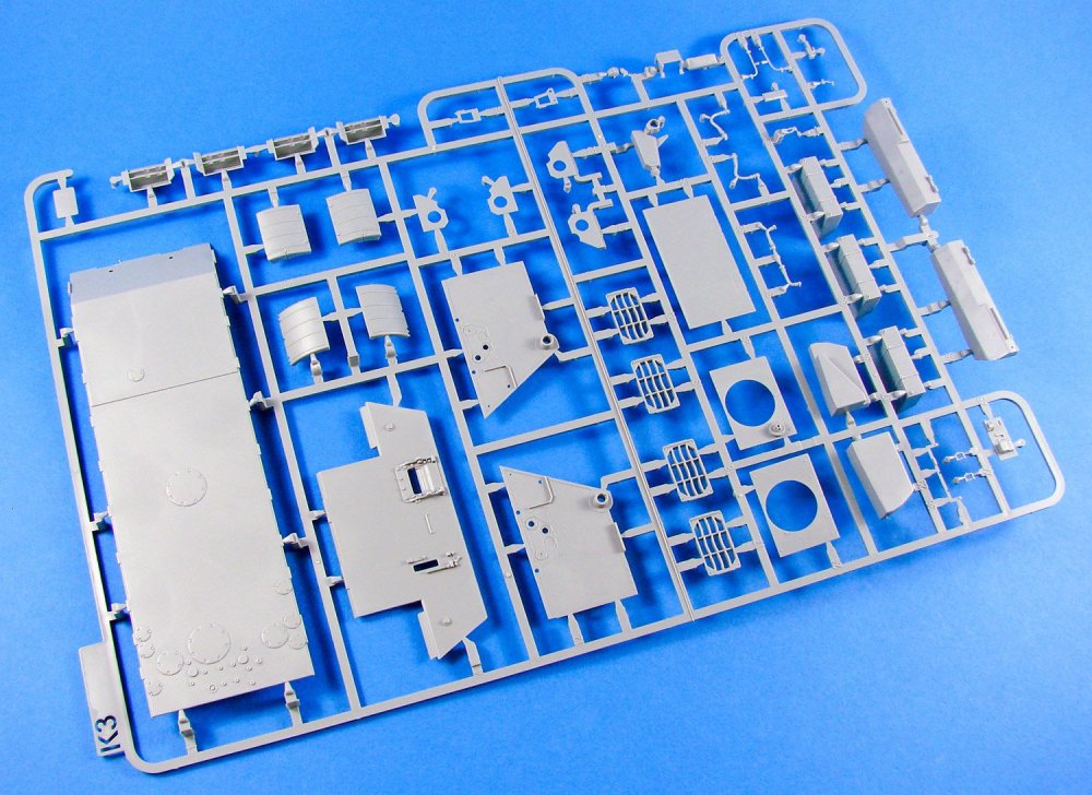
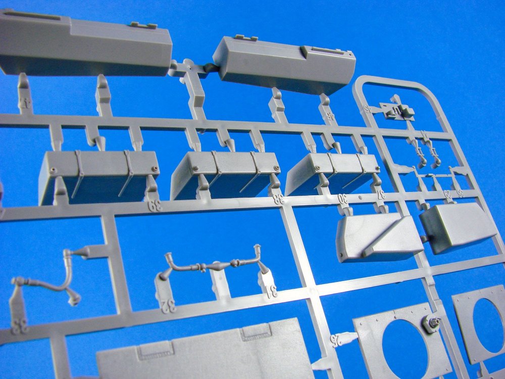
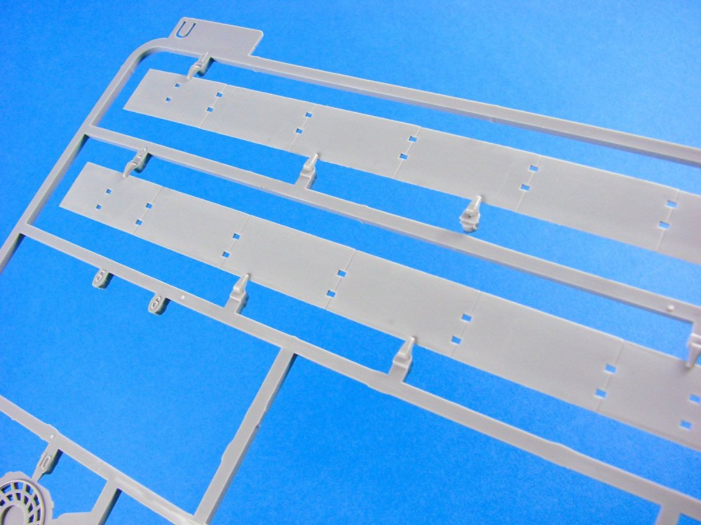
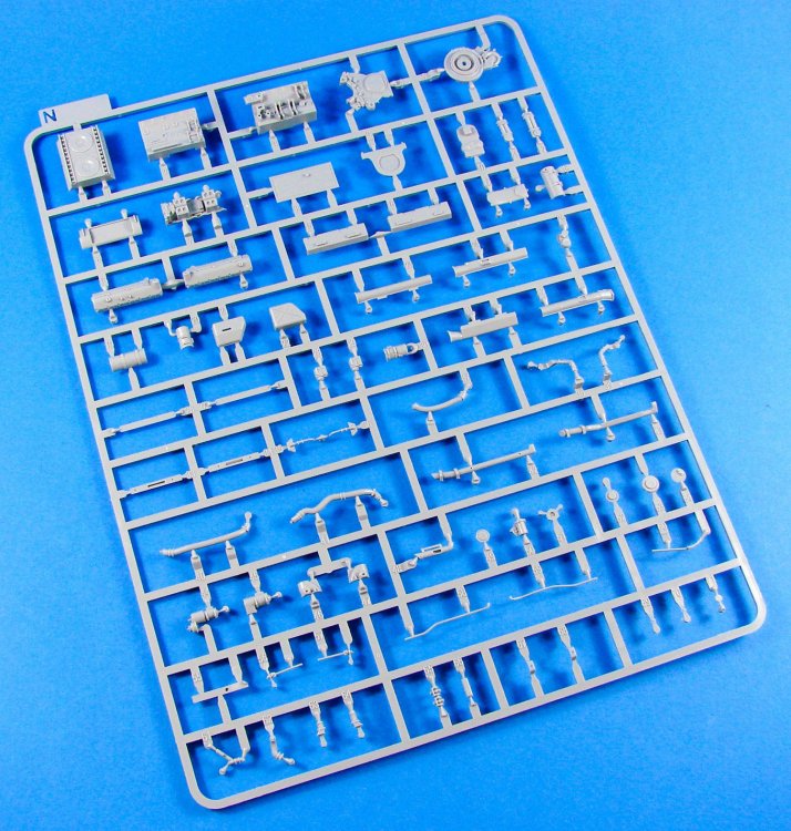
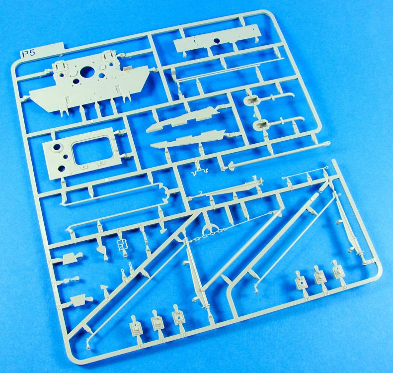
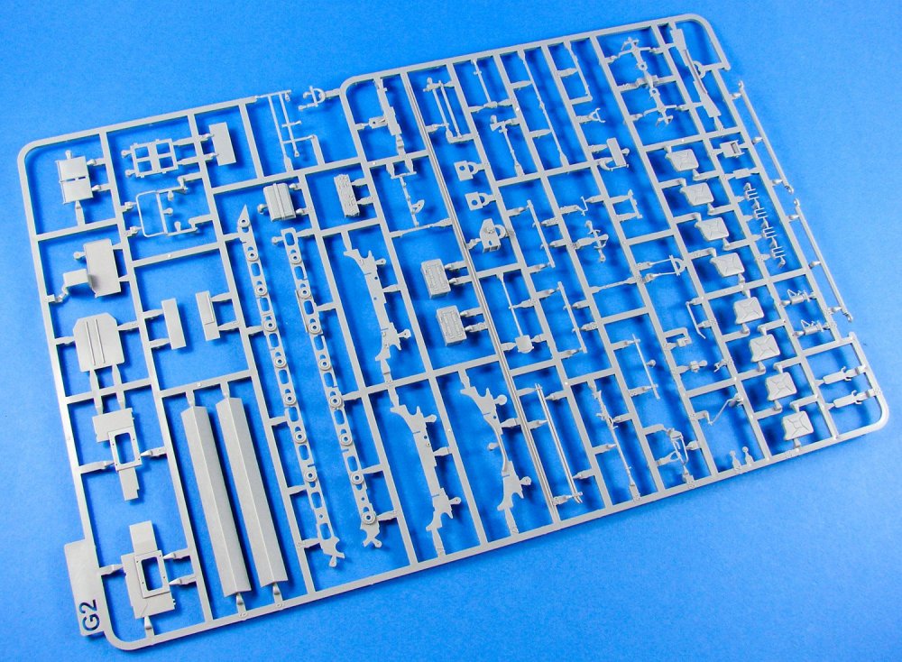
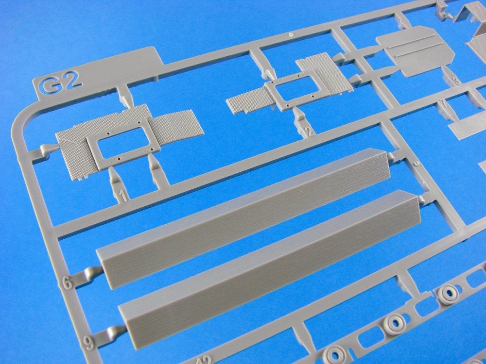
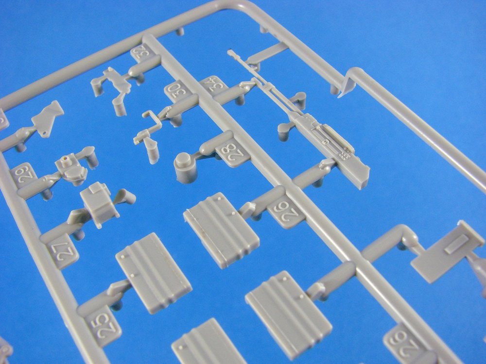
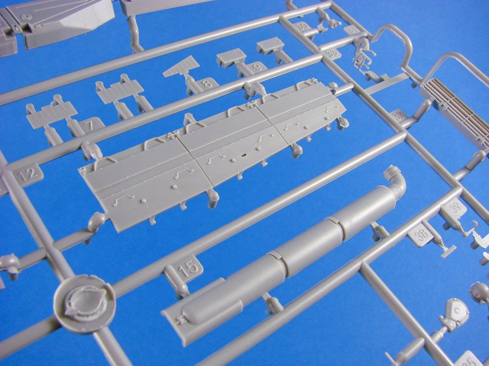
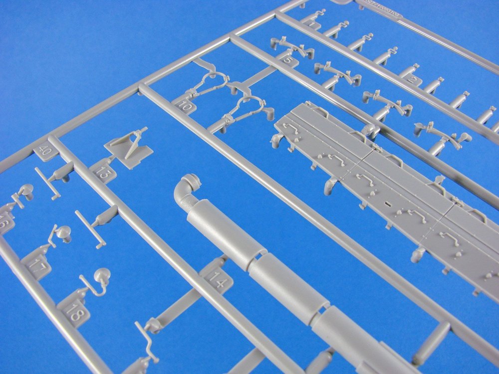
In total, this kit contains TWENTY-FIVE sprues of light grey plastic, one upper hull moulding, one photo-etch fret, braided copper wire, two sizes of metal chain, nylon cord, and a single decal sheet. All sprues are individually bagged except for the multiples. The remaining, whilst occupying the same sleeve, are folded over on themselves so the contents don’t foul each other. Lastly, two black plastic track assembly guides are supplied. These also serve as alignment tools for the swing arms.


Invariably, quite a portion of this new release will be the same as that of the Panther Ausf.A I reviewed HERE, and the recent Zimmerit Ausf.A that I looked at HERE. As with these previous releases, this new Bergepanther also has a full interior. For clarity, areas of this review will mirror that of the previous, with the exception of the new sprues. I feel this is a better way to present this article instead of just showing you new parts and then having to run off and read about the standard Ausf.A sections.


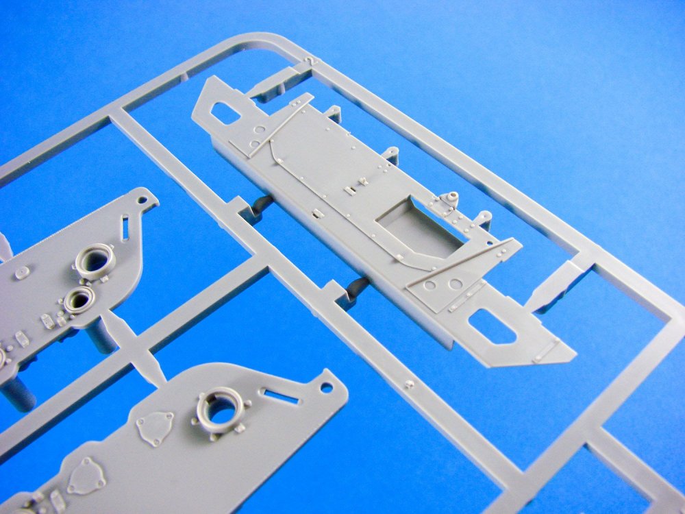
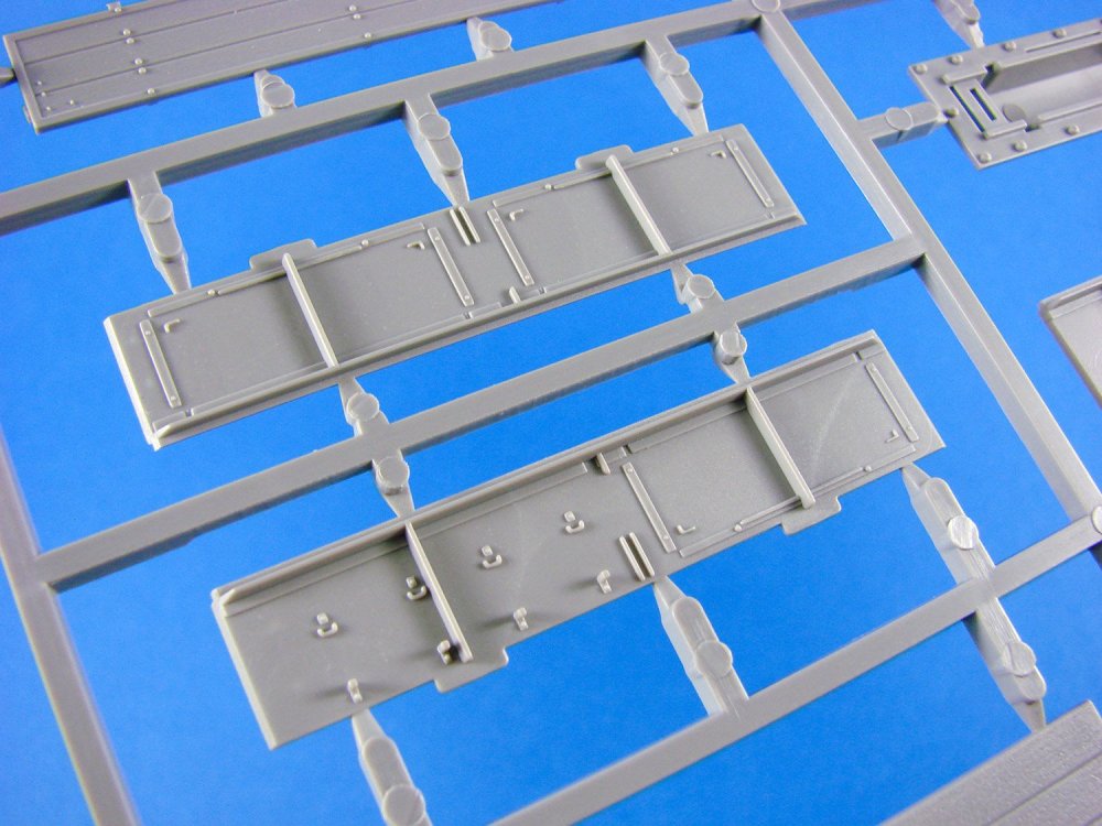
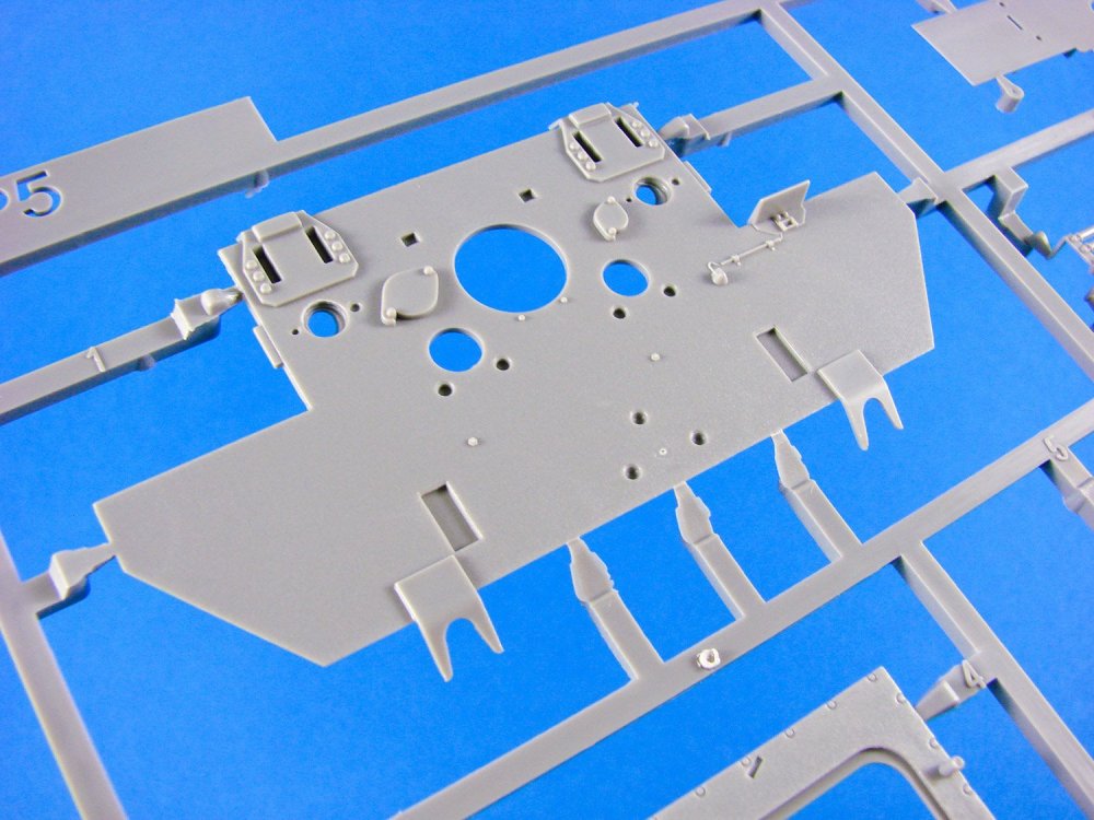
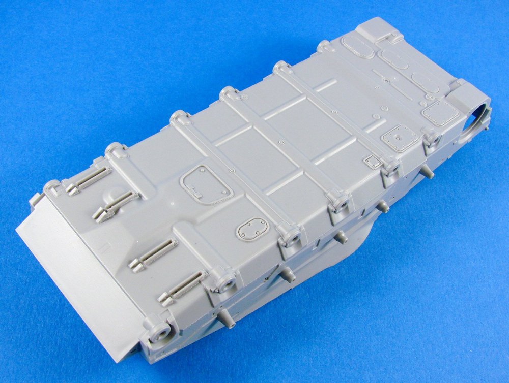
A quick look around the kit contents and you’ll notice a lack of the usual bathtub-style lower hull. For their Bergepanther releases, Takom has chosen to break down everything into constituent components, such as the hull floor, hull sides and forward lower glacis, although the latter is fitted to an inner plate that is connected to the floor. The reasoning behind this is to make everything as accessible as possible to the modeller as they progress through these easy hull construction stages where the frames, transmission, brake drums and torsion bars are to be fitted. Unlike Rye Field Model, Takom provides the lower hull frames as plastic parts, as opposed to their competitor who supply these in photo-etch. Both options work great for me, with perhaps the plastic parts being easier to fit and align. They are also moulded, as with the rest of the interior, with huge finesse. My test assembly of the initial release proved that this is a superbly engineered and moulded kit that should present no problems, provided you follow the chronology.
A few very light ejector pin marks are found here and there, but these seem to be hidden by subsequent construction. Before the sides are fitted to the hull floor, they are fitted out internally with the brake drums etc. These side plates are moulded with the torsion tube sleeves in situ, so there shouldn’t be any wall to wall alignment issues. With the walls complete, these glue into place. Takom would have you insert the torsion bars before this, and as they don’t extend to the hull exterior, it might be wise to do as they say, but dry fit them in case you have any minor alignment issues that could arise from gluing them in place from the start.

The swing arms are next to be fitted, and to help with absolute positioning, two plastic jigs are included. These have alignment holes for the swing arm axles to fit into. Takom hasn’t designed this kit to have articulated swing arms, so if you want to pose the model whilst sitting on uneven ground, this is the time for you to look at that and mock things up for later.

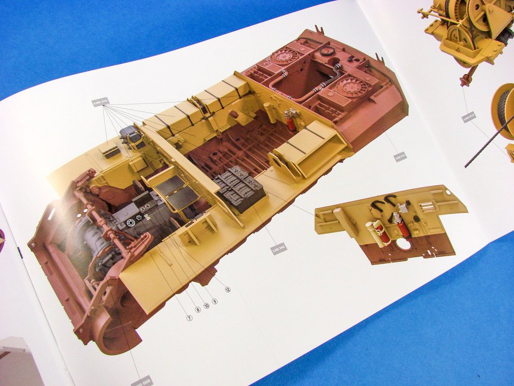
It’s now the time for the interior to be fitted out, and this is no quick task, even with the lack of ammunition/storage in the Bergepanther. Even without the many ammunition shells and their storage racks, you still have what is probably one of the busiest detailed interior that I’ve seen in any kit thus far. Work progresses with the installation of the crew seats (moulded rear spring detail unlike the PE of the RFM release), interior walls and bulkheads, radio sets, drive shaft. No turret floor is fitted to this machine as even this element was removed during the conversion process.
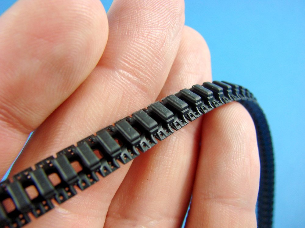
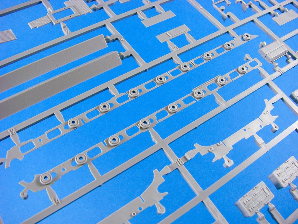
I hope you didn’t throw away the swing arm guides as these are now used to create the shape of the tracks. Onto the guides will plug the drive and idler wheels (no glue!) and then the tracks can be formed over the curves of the guide, with the drive/idler/track assembly being transferred to your lower hull. FOUR sprues of track links and associated parts are included, incorporating several completed sections of track, along with many separate links. None of the track links have moulded horns. These are provided as separate parts that are moulded to a tree that you install as a single piece, and then when dry, snip away the tree from the tracks. That’s a smart move that will save some swearing. After building the demonstration model, I can tell you that the tracks assembly without any trouble whatsoever.
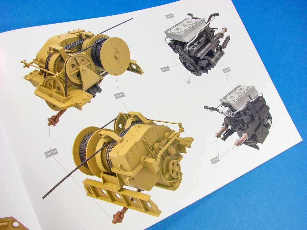
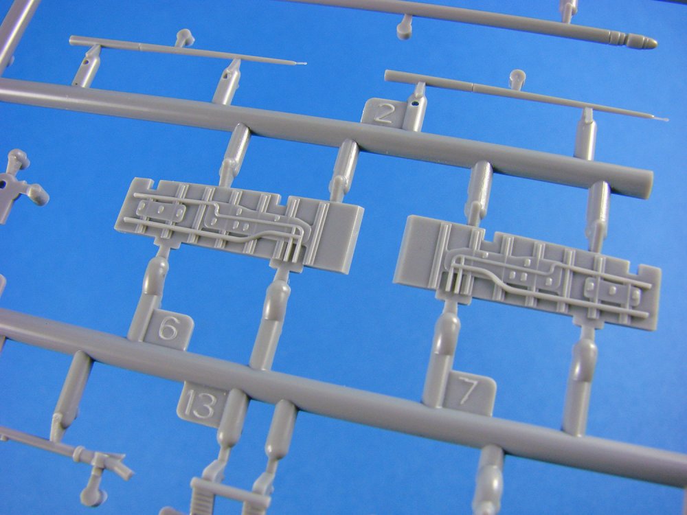
The Bergepanther’s Maybach engine is faithfully reproduced and is a project in itself, complete with its plumbing that interconnects to the engine bay walls. This, along with fuel tanks, engine cooling apparatus and more internal framing. This is a model for which you will need to carefully plan each painting and weathering stage ahead of getting to that part. You will need to ensure careful and accurate alignment of the engine for it to be able to mount properly and accept the plumbing. It’s a very cramped compartment back there!


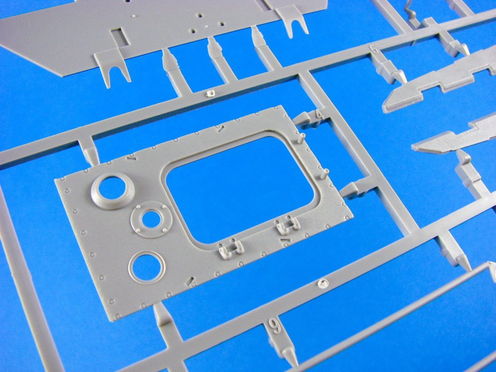
A single-piece upper hull is included with sections missing for the crew compartment, engine and engine cooling. These are moulded as separate parts, thus maximising the opportunity to show the interior of the model to its fullest potential. Even so, you would still be limited, under normal circumstances, to pose these off in any realistic way. The best plan with the Bergepanther would be to leave the wooden structure un-glued so that it could be viewed by lifting it off. The driver access plate on the upper hull, won’t be fitted to the Bergepanther, allowing a minimum of immediate interior visibility as it will still be somewhat hidden under the tarpaulin that extends from the front of the wooden structure. A bit like an early version of a sun-roof!

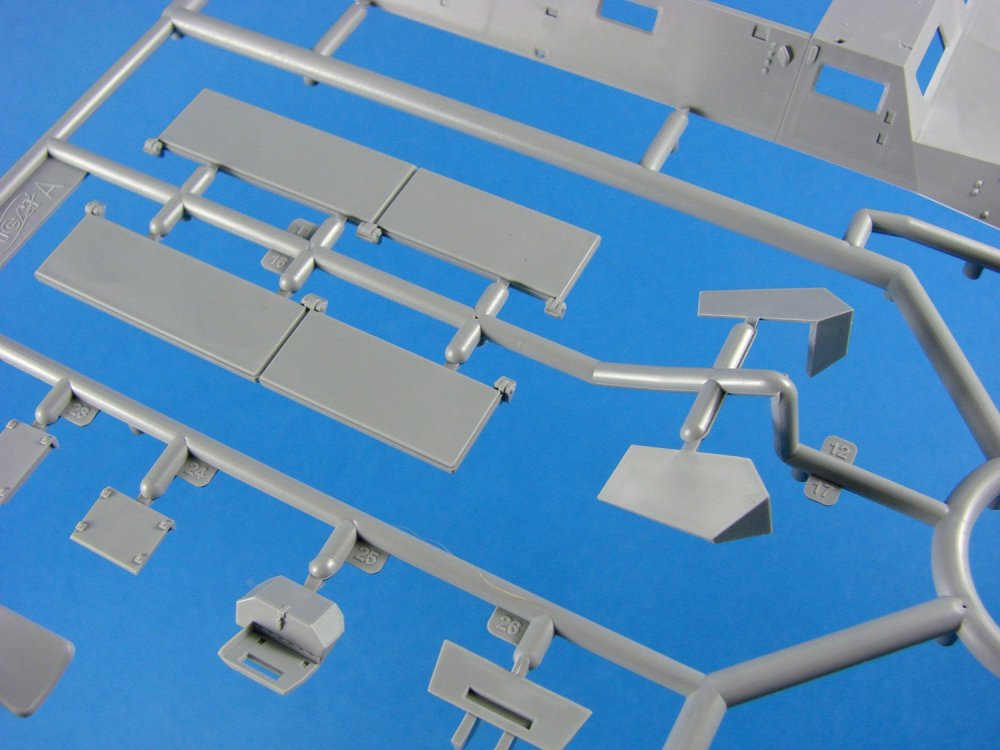
This kit has SEVEN new sprues that are of course specific to this version of Bergepanther and/or the Ausf.D release. In the case of the latter, the Bergepanther-specific sprues in this kit are devoid of the parts for the other version, as can clearly be seen by the large voids in some areas. One standard Panther sprue also has many parts missing, as they aren’t pertinent to the Bergepanther.


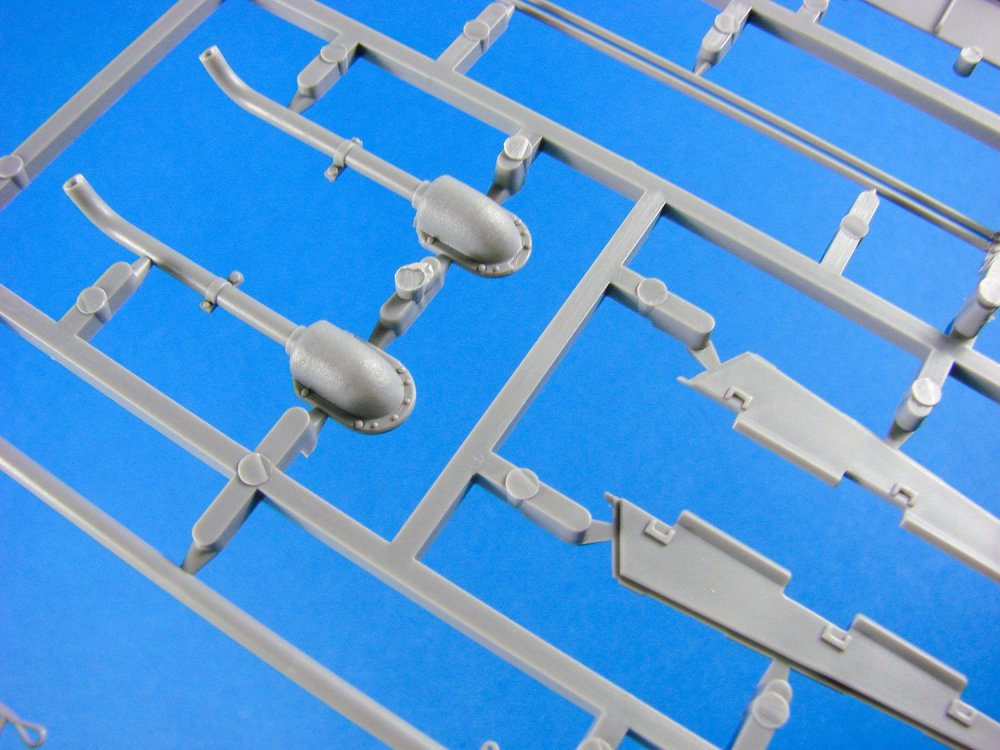


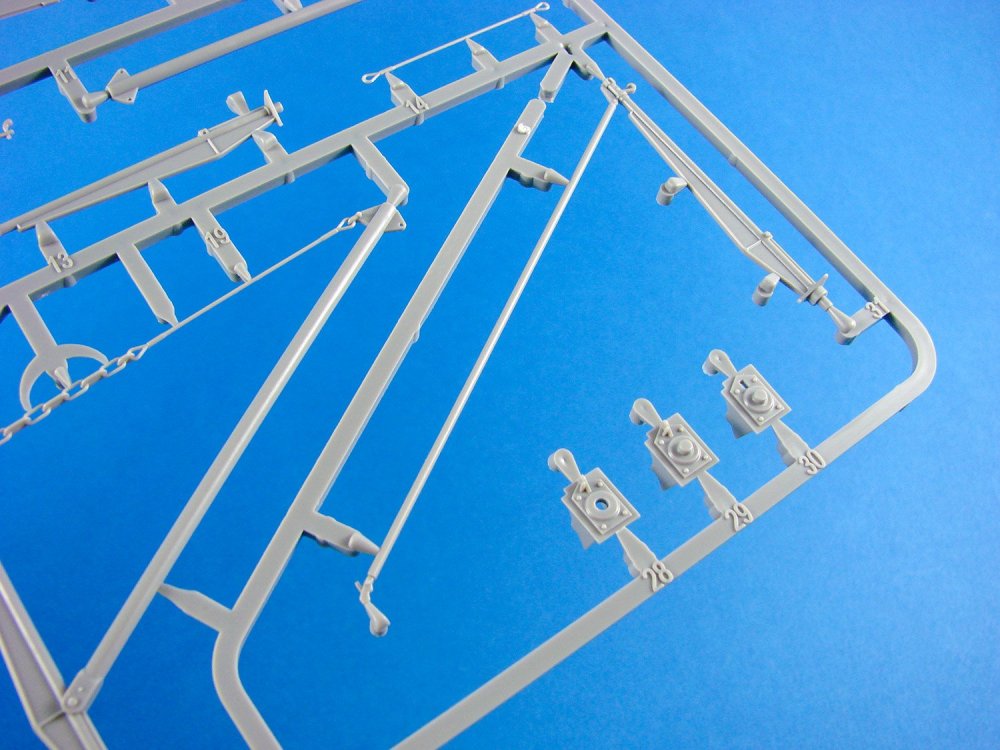
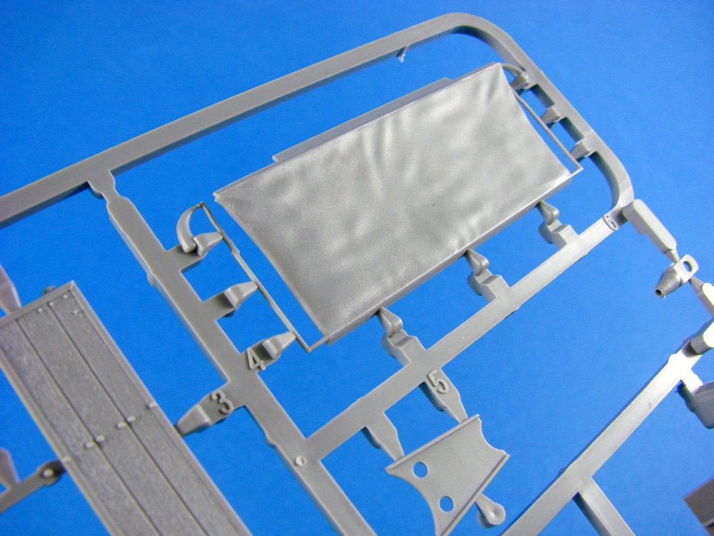
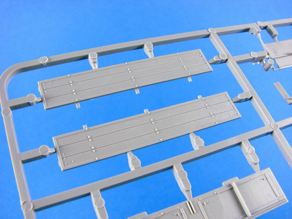
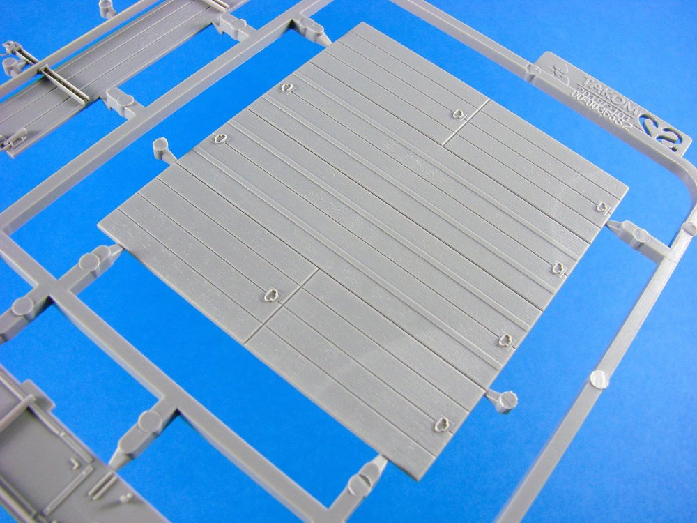
The new sprues have the same detail hallmarks that we can see from the rest of this kit, with rather nice moulding touches too, such as the integral chain detail (metal alternative provided), and the various winching wheels with their grooves. Of course, the recovery spade which raises and lowers from the rear of the Bergepanther, is also a beautiful piece of moulding that employs the latest techniques available to companies such as Takom. There isn’t any option for posing anything in an open position on the wooden structure, so you may want to leave loose. A very fine wood grain detail is moulded over such parts, and the large metal straps, locking clasps and brackets are superbly depicted. Also of note is the tarpaulin with its realistic sagging texture. I would’ve liked to have seen an option for this to be retracted, but we can’t have everything!
Photo-etch, chain. etc.
For such a comprehensive kit, there is surprisingly little PE in this release, with Takom opting to create many of the finer parts in standard injection plastic. Only six pieces of photo-etch are included in this release, and these are for the engine cooling grilles on the rear top deck. The mesh is certainly fine enough to pass muster, and the quality is excellent.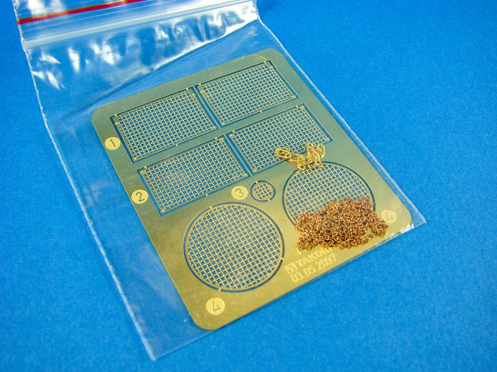
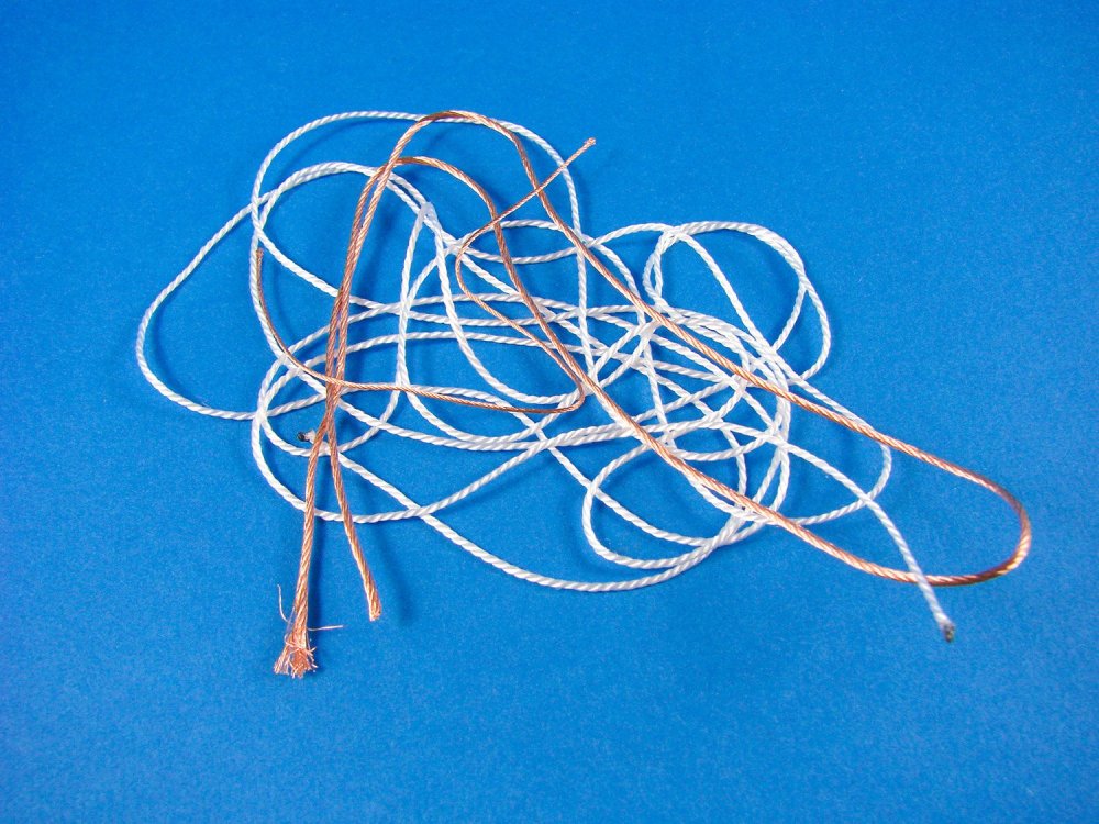
Two small lengths of chain are supplied, of different gauges. These are of course for the block and tackle/pulley system that hangs from the Bergepanther’s lifting arm, and a section for the arm itself. Whilst the arm has a superb section of filigree-moulded chain, you may want to use a real section for more authenticity. It could come in quite useful too if the plastic detail breaks under ham-fistedness.
Decals
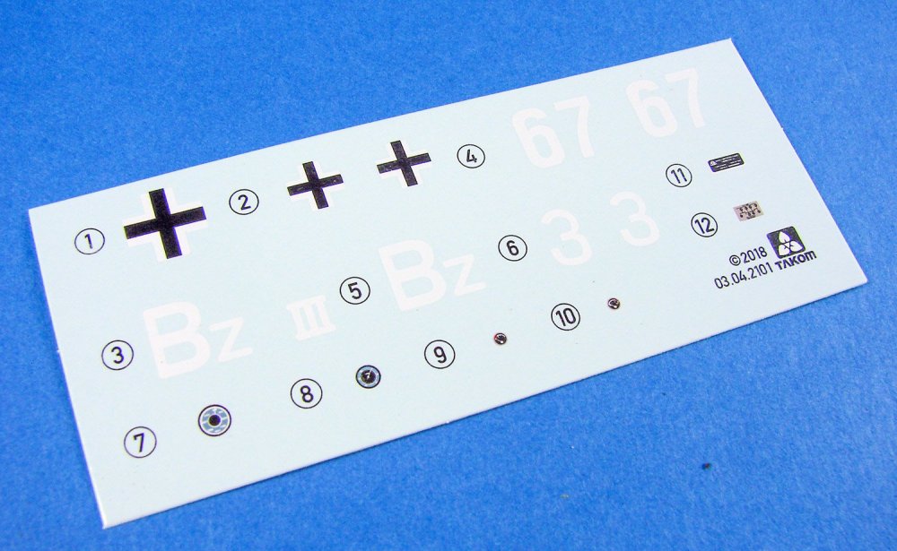
The decal sheet is quite small and contains the markings for FOUR schemes. Printing is thin, has minimal carrier film and is in perfect register. Those schemes are:
- Western Front, 1945
- Captured, Bovington, 1945
- Hungary, 1945
- Western Front, 1943

Instructions
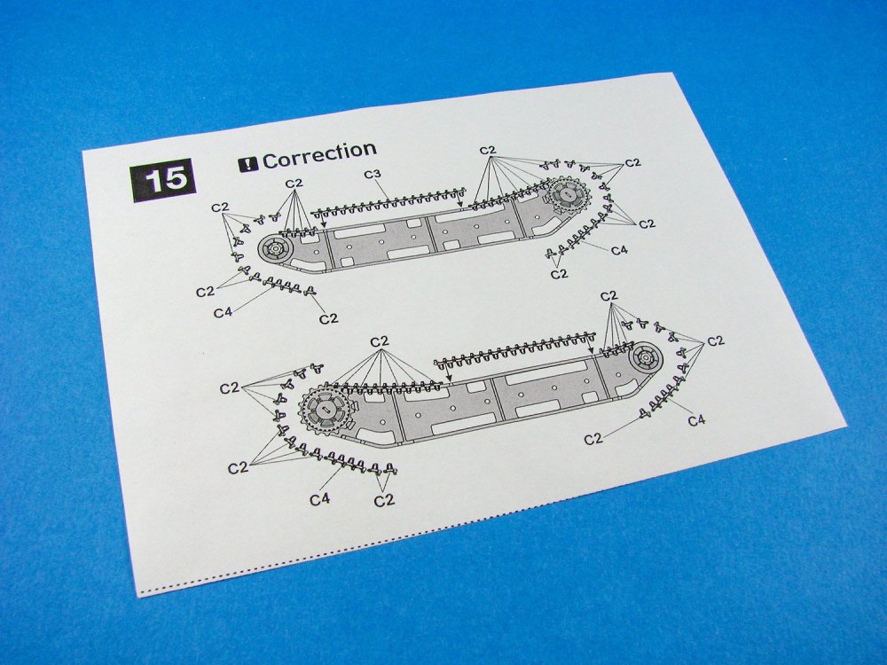
A 34-page A4 manual is included (landscape format) which breaks the Bergepanther down into 54 constructional sequences. Don’t let that fool you though, as you can probably triple that number with the addition of sub-stages per sequence. As I said, this is no quick project. The cover of the manual gives a history of the type and we then get a comprehensive parts map showing each sprue, decal sheet and PE fret. Most of the constructional imagery, provided as shaded illustrations, is printed on matt paper except for where corresponding leaves are printed on gloss for the numerous colour illustrations, courtesy of AMMO. These images provide priceless info on interior painting and will save us countless hours trawling the information either online or in books. Painting reference is also provided in AMMO reference codes. The last pages of the manual are given over to the four schemes provided with this kit, printed in glossy colour and with more AMMO paint references to negotiate. Inside the manual, a small correction sheet is included for the track building section.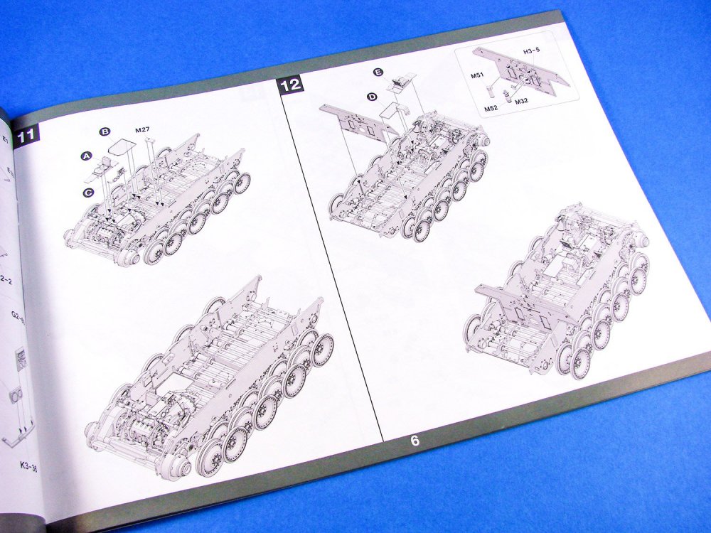


Conclusion
For me, I put this as perhaps being the best Panther/Panther-relative kit that Takom has yet produced. It has everything in that it’s one of the most detailed 1/35 models on the market, plus the esoteric-factor. This really is one that will catch the eye in your cabinet or model display stand. It really does cry out for a diorama though, showing off the best elements of the Ausf.A design to their maximum potential.My sincere thanks to Takom for sending out this kit for review here on LSM. To buy this kit, check out your favourite local or online retailer.

-
That really transforms it. Can't wait to see this installed on a finished model
-
1:35 U.S. Tank Crew
MiniArt
Catalogue # 37005
MiniArt really do create some superb sets to aid the diorama modeller, whether it be something as simple as a wartime domestic scenario, or the popular vehicles and figures combo. We recently reviewed the East European House Stuff kit containing table, chairs, and domestic items, but today we’re going to zip forward a few decades to look at a set that’s been designed to complement your U.S. armour builds.
Photo courtesy of We Are The MightyWhilst it’s quite vogue at the moment to produce armour with full interiors, the majority of kits on the market don’t possess that level of internal detail, yet still allow the modeller to pose the various hatches in the open position. Maybe not too good for a solitary vehicle on a display shelf, but certainly perfect for adding some figures. This new set from MiniArt depicts FIVE modern U.S. tank crewmen, and would be ideally suited for displaying with one of the many Abrams releases, for example, or indeed any other piece of modern U.S. armour (Bradley, Stryker, M1117 etc.)

The kit itself is packaged into an attractive end-opening box which has an image of the combatants on the front, and an individual painting guide on the rear, despite the fact that the crew themselves are very similar in outfit. These rear illustrations also serve as an assembly guide for the crew, with the poses being clearly seen and the parts/appendages numbered for clarity, with a sprue letter annotation. The camouflage fatigues themselves are actually finished in a digital camouflage, and this could be difficult to recreate, but I’m sure there must be a few tried and tested techniques to produce this, including decals from companies such as CrossDelta.
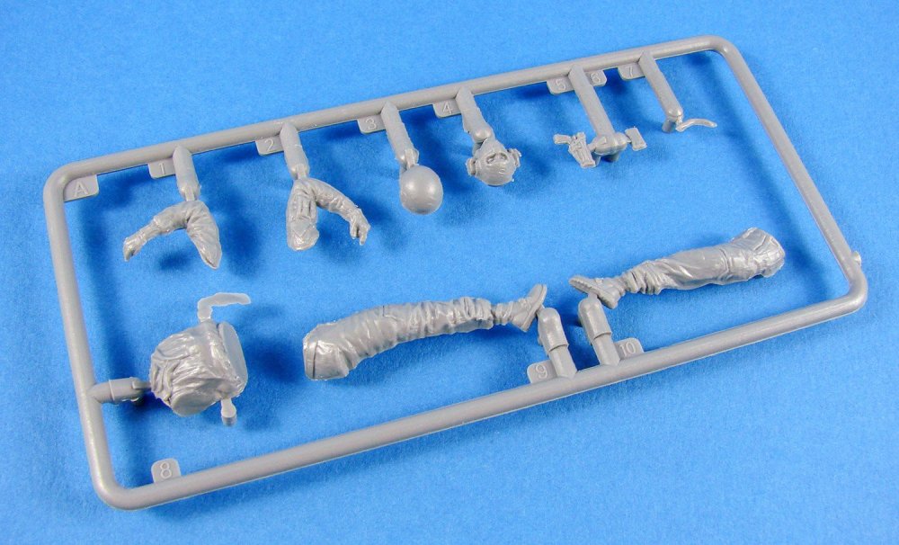
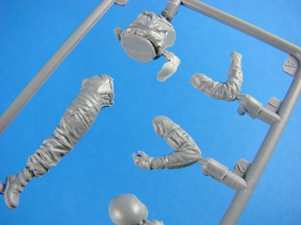

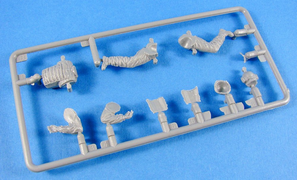
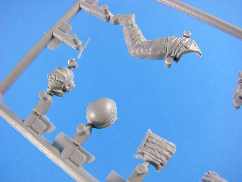
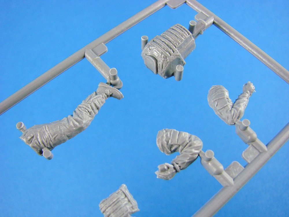
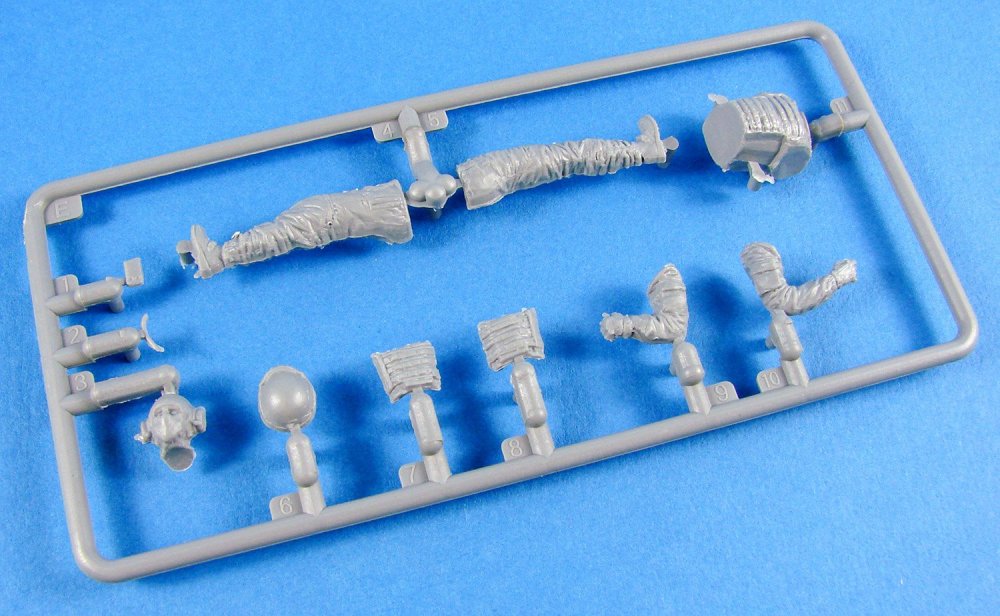
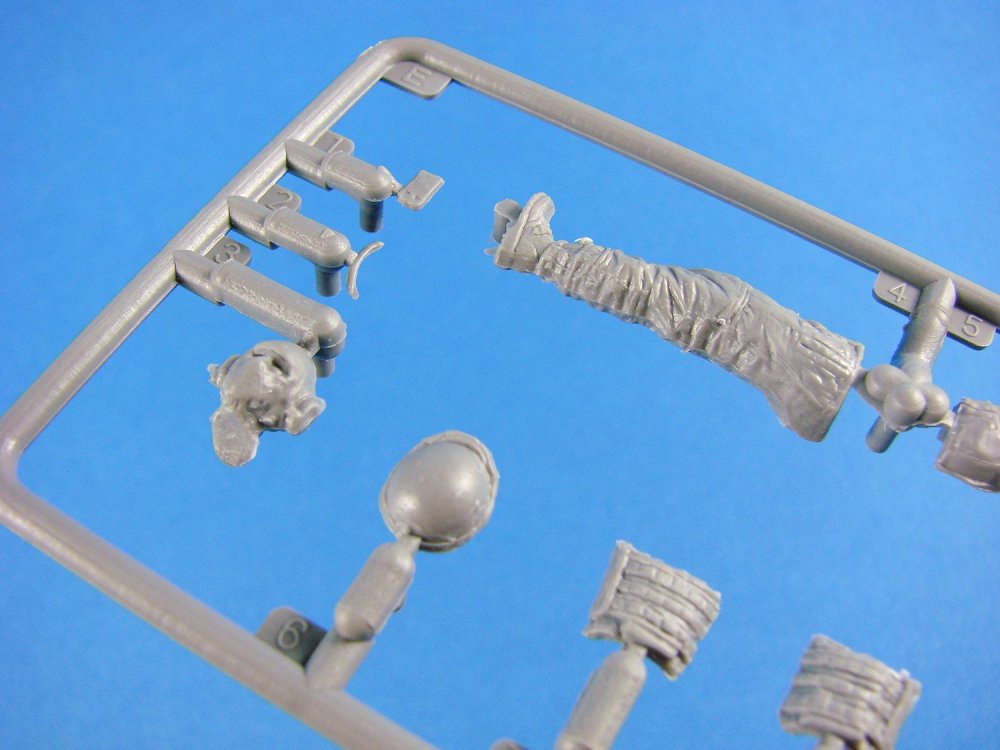
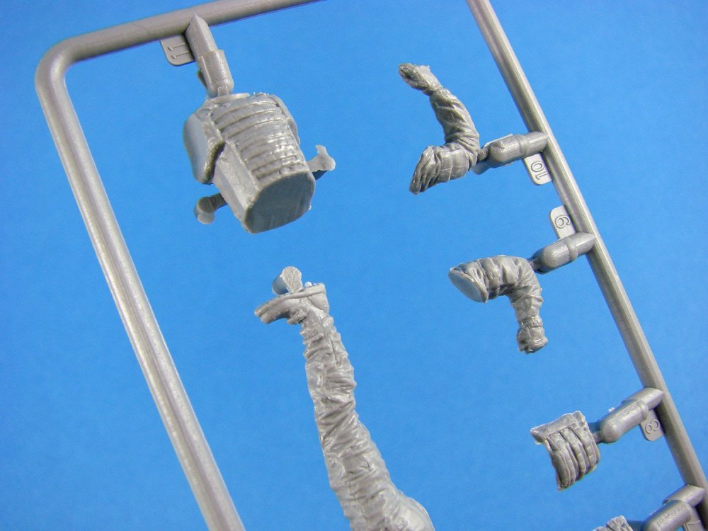
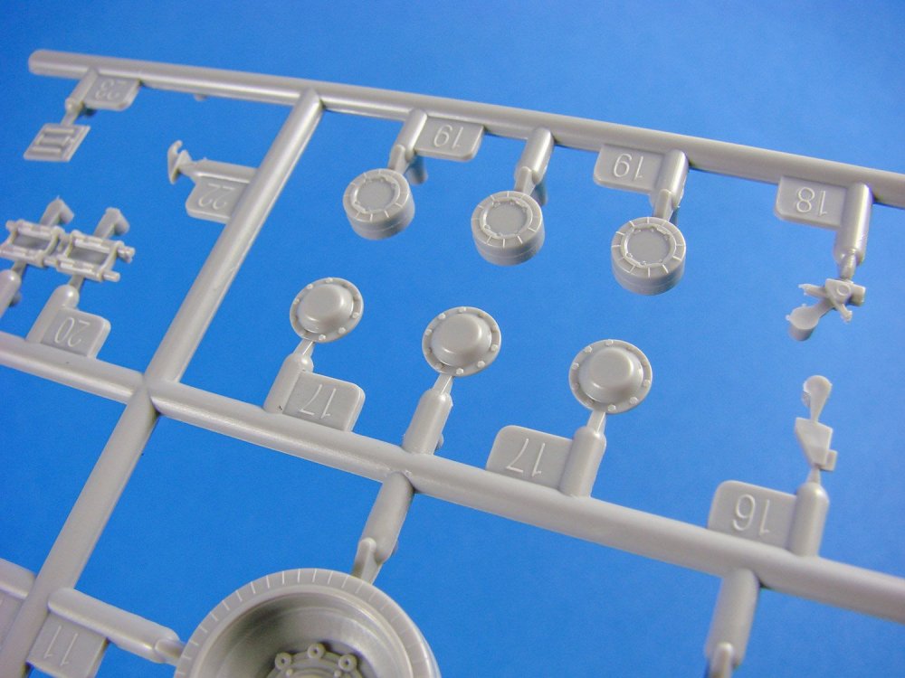
Inside the box, a single clear sleeve contains five sprues (3 of which are joined by a master sprue length), and each of these sprues contains the parts for one single figure. Moulding is excellent, with just the inevitable minor seams lines to scrape away, and the breakdown of the figures is obvious. Having separate heads, you can of course pose these even more dynamically so as to perfectly fit your diorama. Helmets are also moulded separately to the heads but leaving a full head underneath in case you wanted to pose the helmet off the crewman. A few other accompanying parts are included on each sprue, such as weapons, mic booms etc.
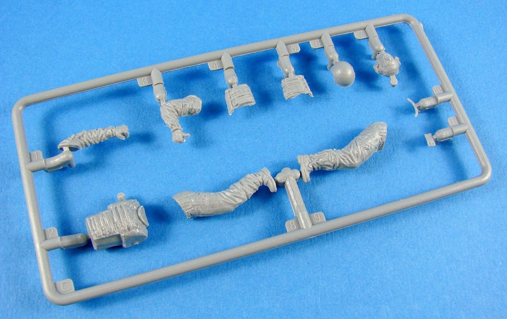

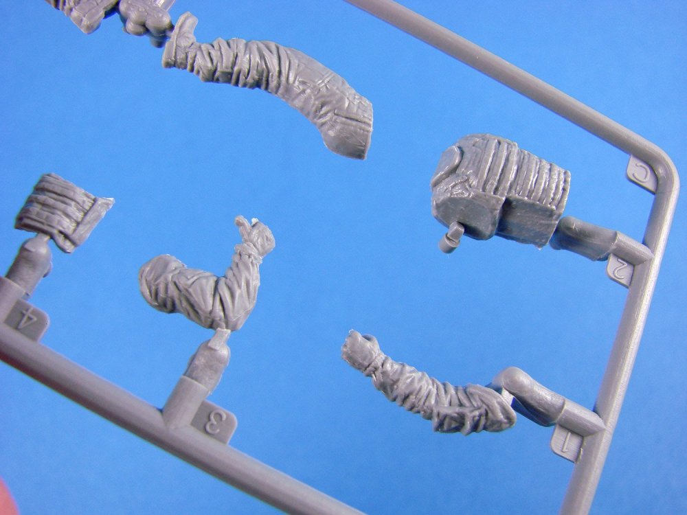


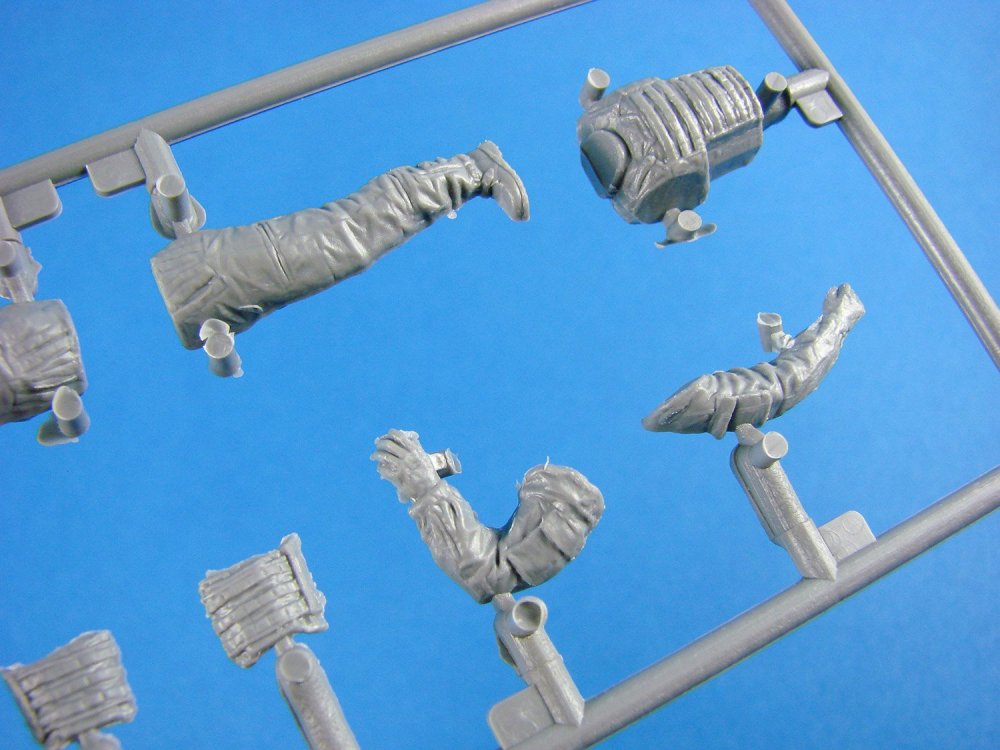
Detail is superb, with realistic fabric folds and creases, boots/straps, and torso padding. Not much can generally be seen of the faces due to the uniform. All poses are very organic/natural in appearance and would suit just about any application you have in mind.
Conclusion
A simple yet effective and detailed set that should sate your appetite for U.S. armour dioramas. The set itself is also quite inexpensive, and most certainly in comparison to resin figures. Assembly is a breeze, and it’s just the camouflage application that you would need to overcome. In all, a seriously nice release.
My sincere thanks to MiniArt for the review sample seen here. To buy this kit, check out your favourite local or online retailer.

-
2
-
-
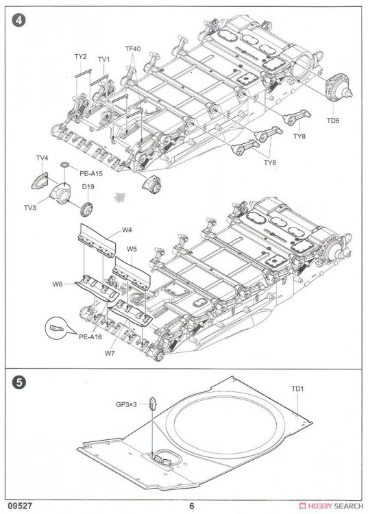
1:35 Russian T-80UD MBT
Trumpeter
Catalogue # 09527
The T-80 is a third-generation main battle tank (MBT) designed and manufactured in the Soviet Union. When it entered service in 1976, it was the first MBT in the world to feature a powerful multifuel turbine engine as its main propulsion engine. The T-80U was last produced in a factory in Omsk, Russia, while the T-80UD and further-developed T-84 continue to be produced in Ukraine. The T-80 is similar in layout to the T-64; the driver's compartment is on the centre line at the front, the two-man turret is in the centre with gunner on the left and commander on the right, and the engine is rear mounted. The original T-80 design uses a 1,000hp gas turbine instead of a 750-horsepower diesel engine, although some later variants of the T-80 revert to diesel engine usage. The gearbox is different, with five forward and one reverse gear, instead of seven forward and one reverse. Suspension reverts from pneumatic to torsion bar, with six forged steel-aluminium rubber-tired road wheels on each side, with the tracks driven by rear sprockets. The glacis is of laminate armour and the turret is armoured steel. The turret houses the same 125 mm 2A46 smoothbore gun as the T-72, which can fire anti-tank guided missiles as well as regular ordnance.
A disadvantage highlighted during combat in Chechnya was the vulnerability of the T-80BV to catastrophic explosion. The reason given by US and Russian experts is the vulnerability of stored semi-combustible propellant charges and missiles when contacted by the molten metal jet from the penetration of a HEAT warhead, causing the entire ammunition load to explode. In parallel with the T-80U and Russia in general, the Morozov Bureau in Ukraine developed a diesel-powered version, the T-80UD. It is powered by the 1,000-hp 6TD-1 6-cylinder multi-fuel two-stroke turbo-piston diesel engine, ensuring high fuel efficiency and a long cruising range. The T-80UD shares most of the T-80U's improvements but can be distinguished from it by a different engine deck and distinctive smoke-mortar array and turret stowage boxes. It retains the remotely-controlled commander's machine gun. About 500 T-80UD tanks were built in the Malyshev plant between 1987 and 1991.
Extract from WikipediaThe kit


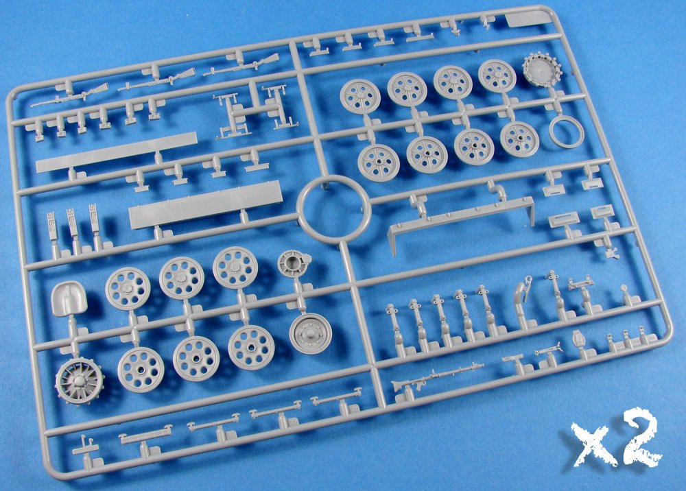
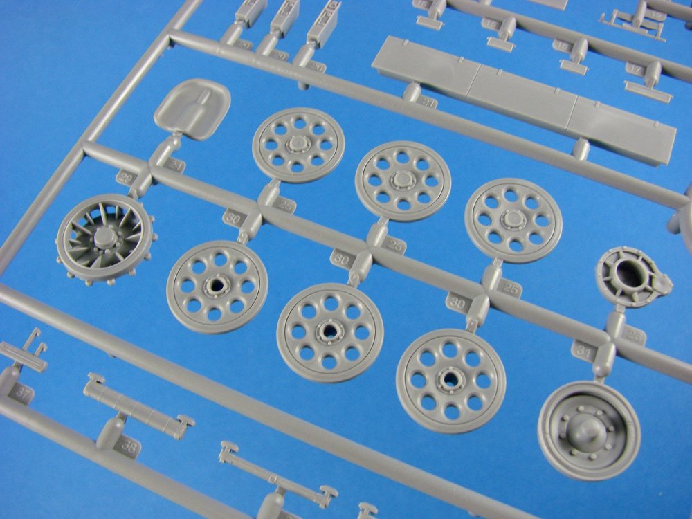
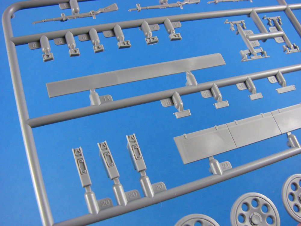
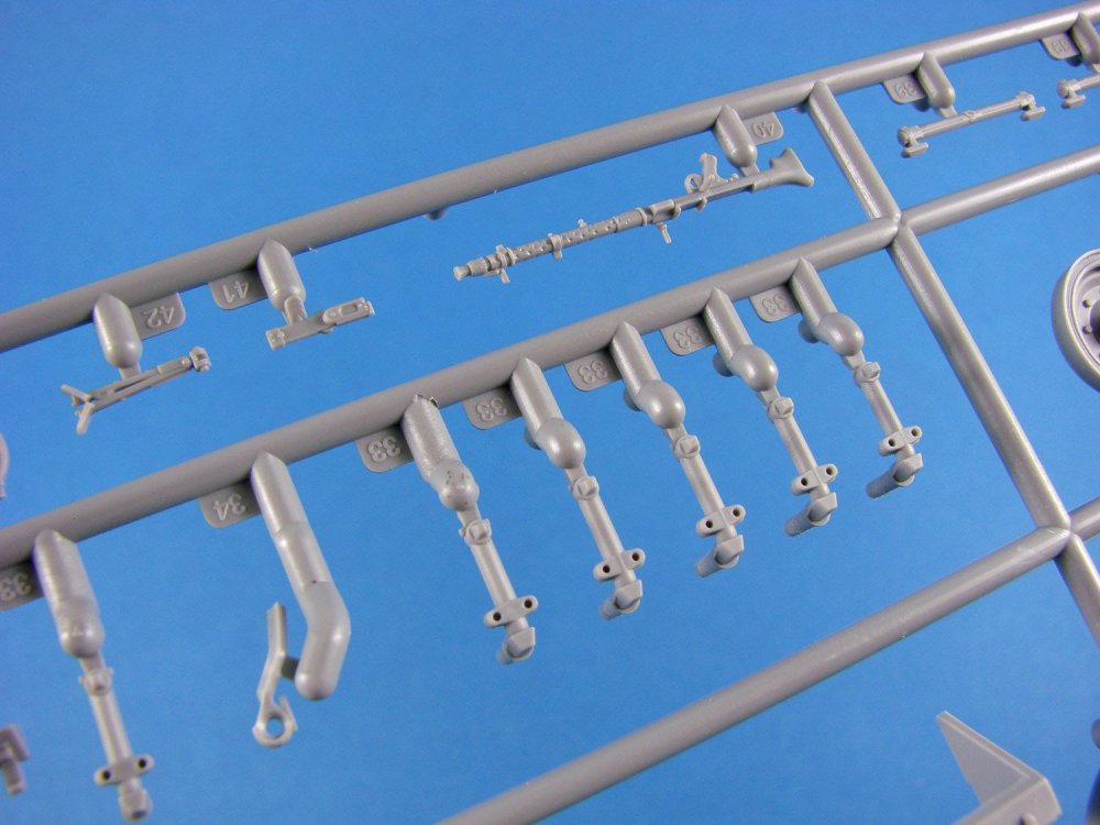
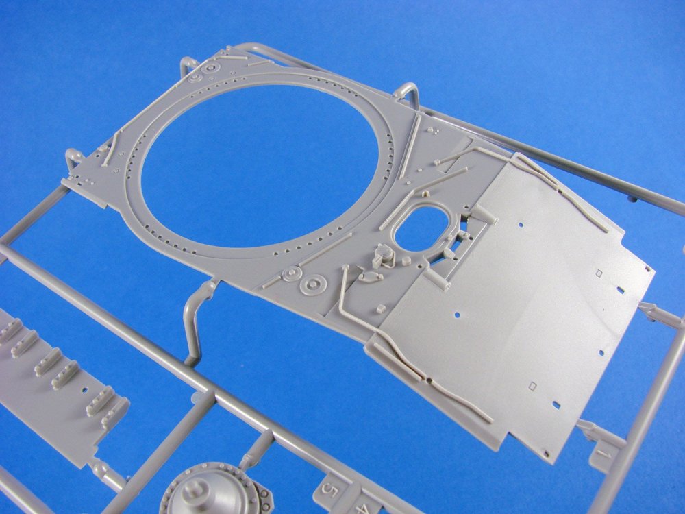
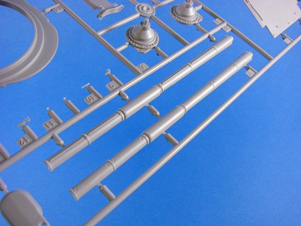
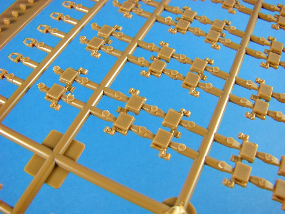
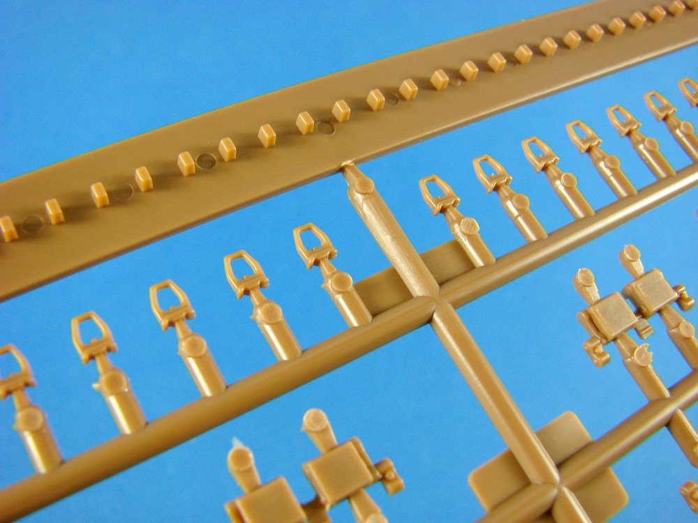
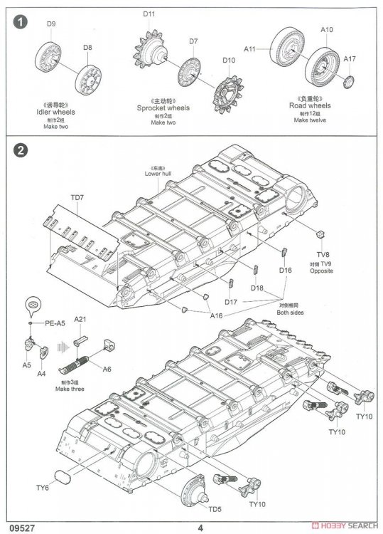
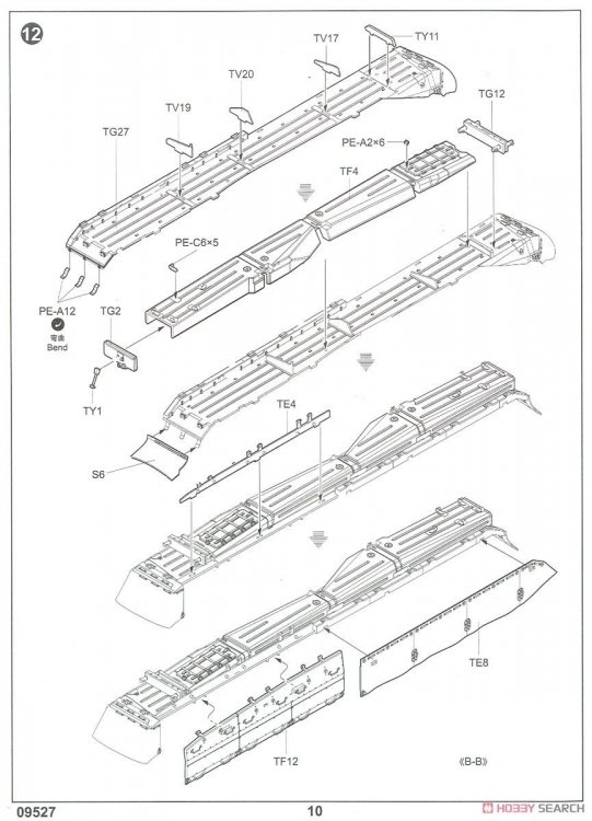
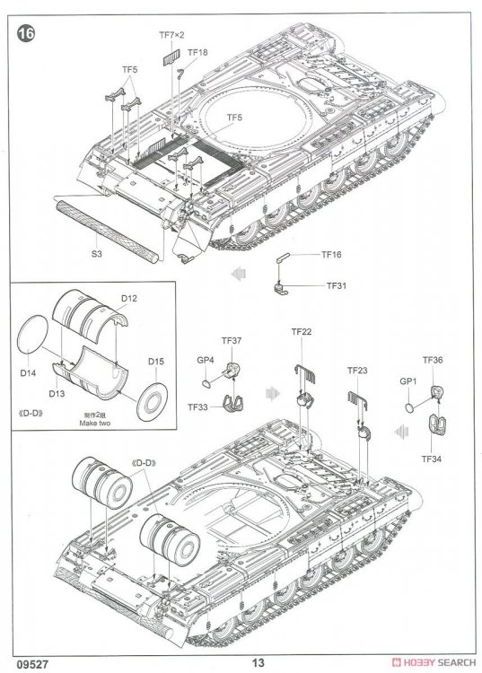
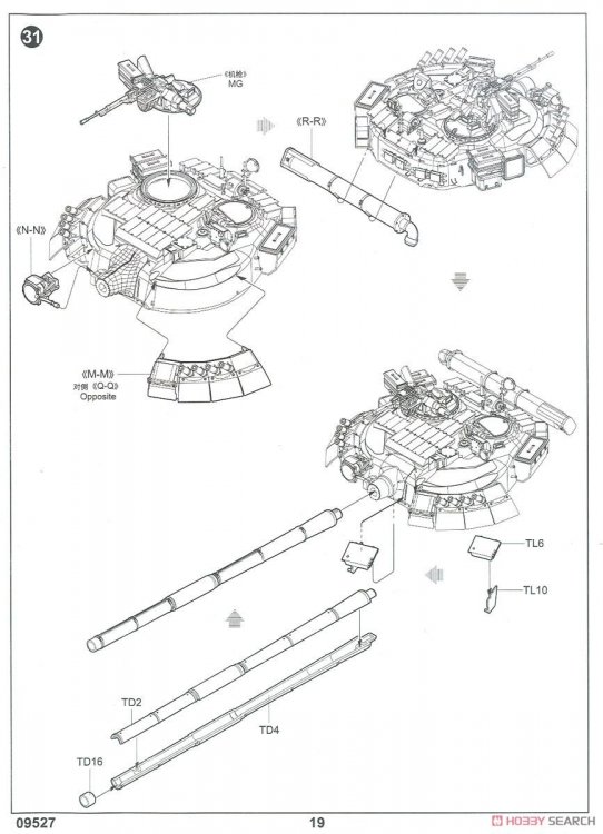
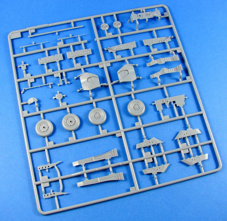
This is certainly a large (48cm x 30cm x 8cm), reasonably weighty and full box of styrene, and Trumpeter say this kit has approx. 940 parts, so it’s no weekend project either. The box art depicts a T-80 on some sort of drive-past/parade on Red Square in Moscow and shows the lines of this vehicle off to a real advantage. Including this 2017 release, Trumpeter’s T-80 has seen around 9 incarnations (including the T-84), up to press, with this of course being the T-80UD, in Russian service. Inside the box, we have a total of 21 sprues, with most of these in light grey plastic, four in brown, and three in an off-white vinyl which can be cemented with your regular brand. These are packaged individually, mostly, except for the multiples of the same sprue.
In the middle of the box, another separate box with a product lid, contains the lower hull, turret, rear engine deck, some of those smaller sprues, decals, braided copper wire, and PE fret. In all, a very busy and attractive kit.


It's generally accepted that the base T-80 is a pretty accurate depiction of this Soviet beast, so I won’t be looking at any elements of accuracy here, plus I’m not qualified to comment on them either.
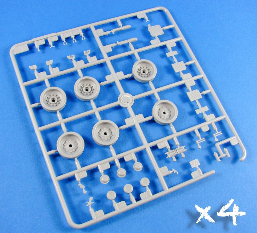
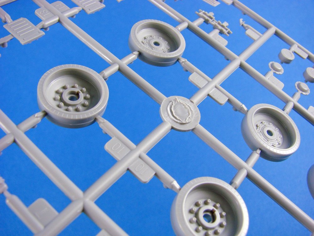


Construction of this kit is broken down into 32 stages over 20 pages, and begins with assembly of the idler, drive and road wheels, spread out over the first six sprues. We then plough onto what I think is the most impressive part of this kit, and that is the slide-moulded lower hull. Typically designed as a bathtub part, the details are just amazing, including the lower forward glacis, torsion bar fairings, access panels etc. Tensioner wheel mounts are also integral, and the various weld seams look excellent. Road wheel holes are also keyed to accept the swing arms and ensure they angle properly. Some rather nifty PE clasps also store what looks to be a section of a log, perhaps for vehicle recovery if bogged down. The log itself is moulded on a flexible vinyl sprue.


The lower hull is massively detailed with a deployable plate that may be something to do with RPG defence or similar. I’m not too sure. In front of this will fit four sections of flexible, cementable vinyl that seem to form a skirt. It’s definitely a nice touch.
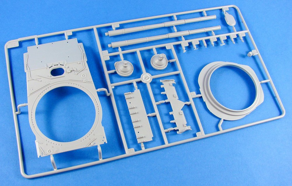


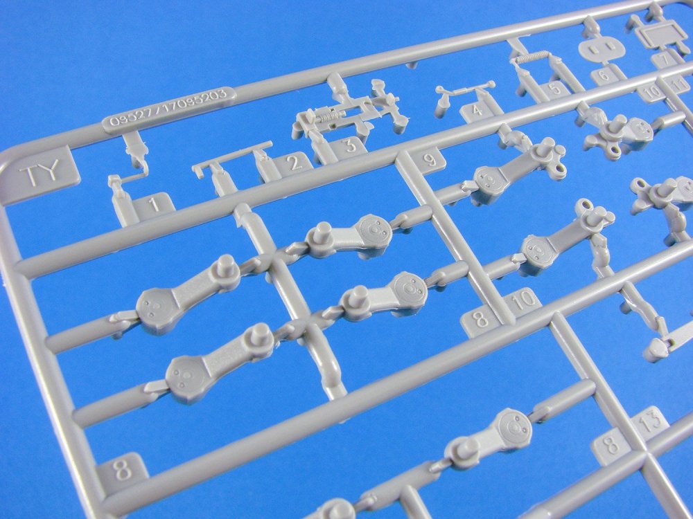


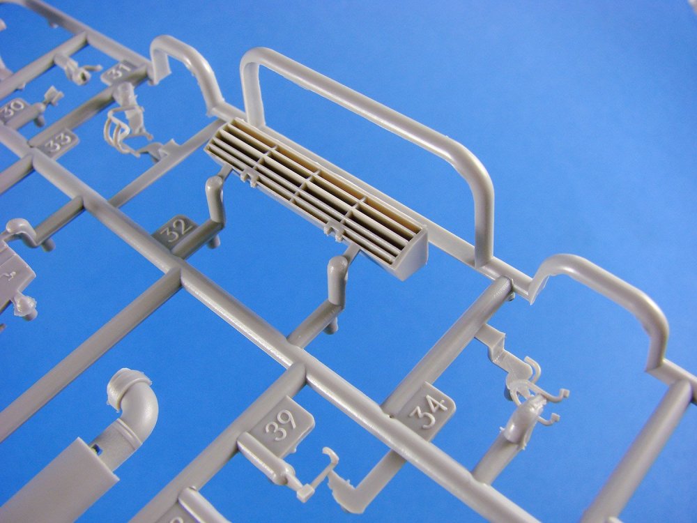
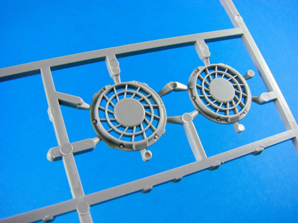
Trumpeter has moulded the upper hull as two main parts with separate reactive armour panel for the forward glacis and a rather nice slide-moulded engine vent for the rear. The latter is bagged separately within the interior box of the kit and needs almost zero clean-up before use. PE engine screen grilles are supplied for this model, as seems to be standard these days.

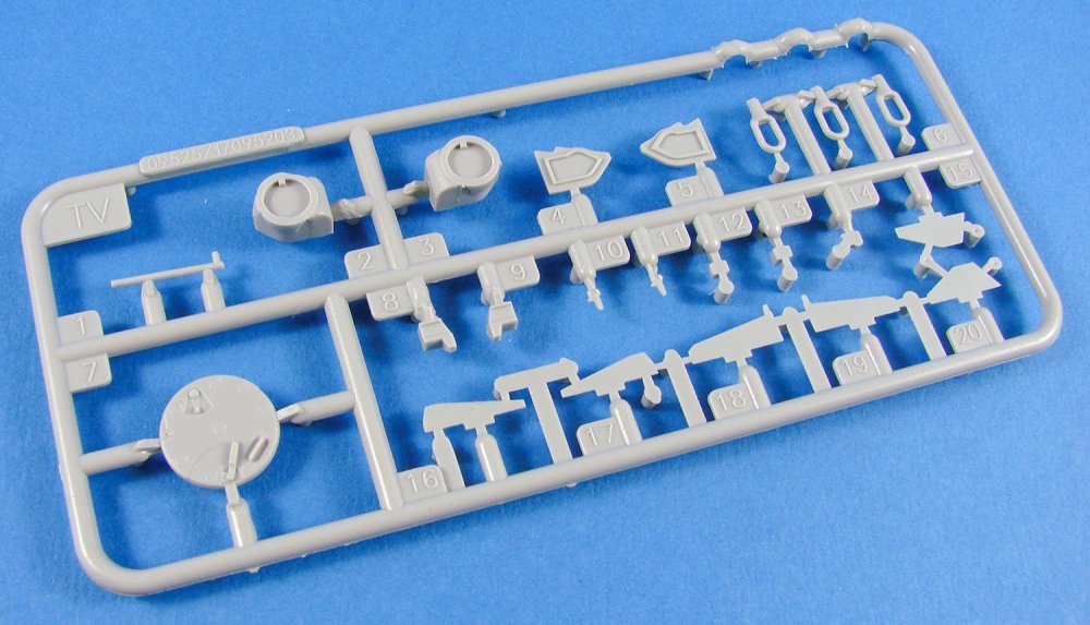
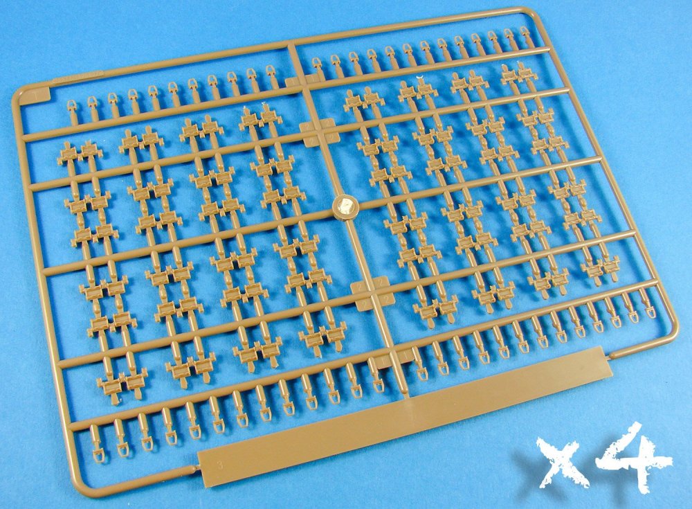
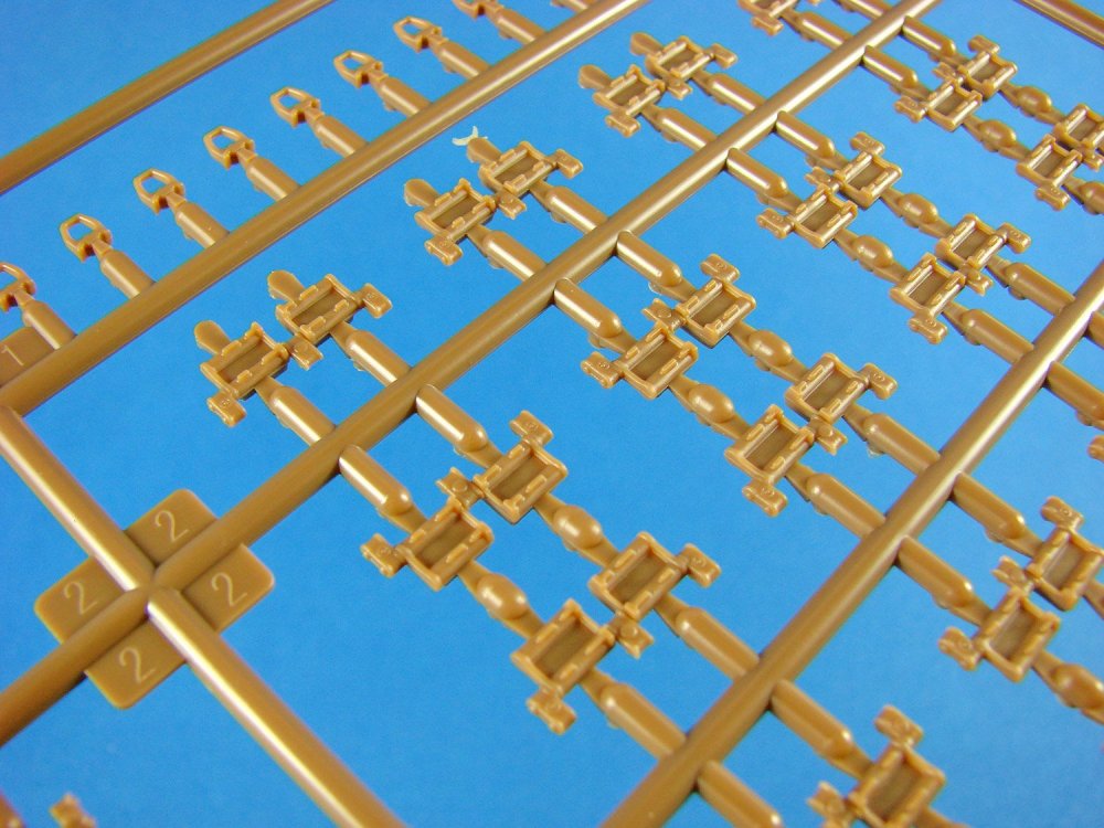
Many of the included parts make up the tracks. These are made up entirely out of individual links, and on top of that, you’ll need to fit the horn to each one. Each side has 82 links, and a jig is included to help you assemble these. They do appear to be workable, or at least to some degree so you can assemble the whole length and then apply to the tank. These parts are moulded in brown styrene, for reasons unknown.
I’m rather impressed with the kit fenders. As with many areas of this kit (turret, tow cable ends etc.), slide moulding has been employed to create a truly 3D part without the need for awkward construction, especially on the forward end of the fenders where many curves are present.

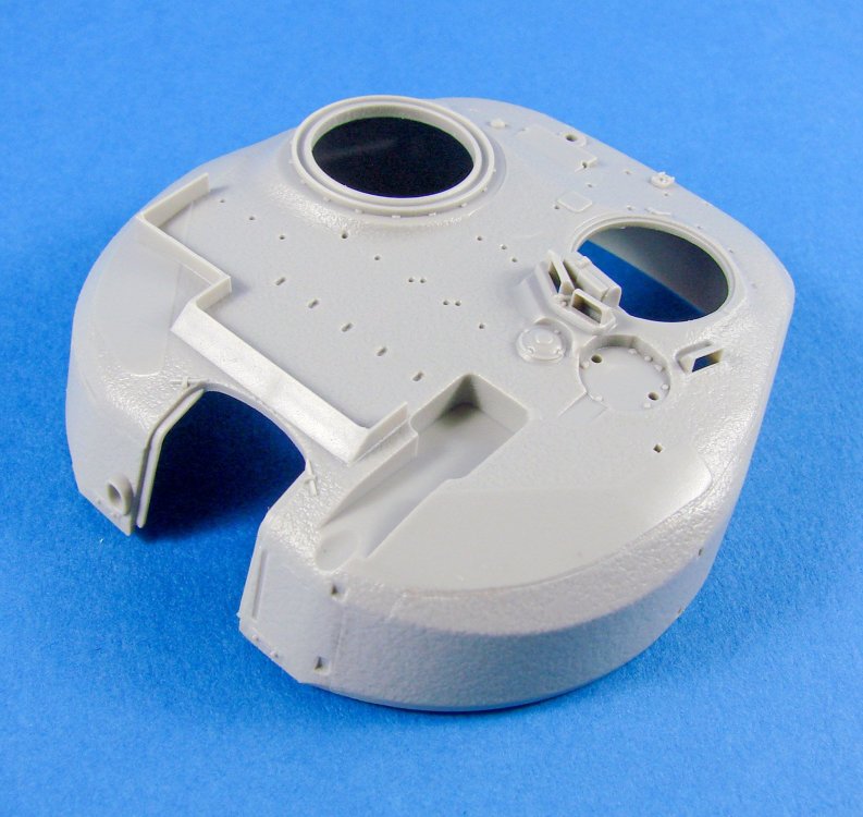

More slide-moulding excellence with the turret. This complex shape has a realistic cast effect, and a separate lower mounting plate. There isn’t any internal detail here, but you can of course pose the gunner/commander hatches in the open position. You’d be better off filling the void with a crew member though. The reactive armour bricks fit separately to the turret. In fact, when you attach all of the various bricks and stowage, very little of that texture seems to be seen!
A three-part barrel is included and for this specific kit, a flexible vinyl mantlet is to be used.

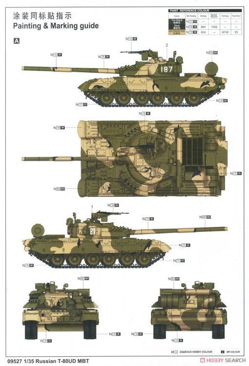

A single decal sheet is included with simple, white printing. This appears to be nice and thin and with minimal carrier film. Three schemes are included with this release, and they are unidentified on the colour sheet that’s included. Paint references are supplied for Mr Hobby, Vallejo, Model Master, Tamiya and Humbrol colours. Trumpeter’s instructions are nice and simple to follow, even with a model with almost 1000 parts. Illustrations are in simple line drawing format and everything is clearly annotated where necessary.
Conclusion
An impressive kit in many ways, including overall detail, complexity of slide-moulded parts, stature and overall presence. I quite like Russian armour, just from its appearance in comparison to regular Western subjects, and this kit ticks all the right boxes.My sincere thanks to Pocketbond for sending this kit for us to review. To purchase, check out your favourite Trumpeter retailer.

-
1
-
-
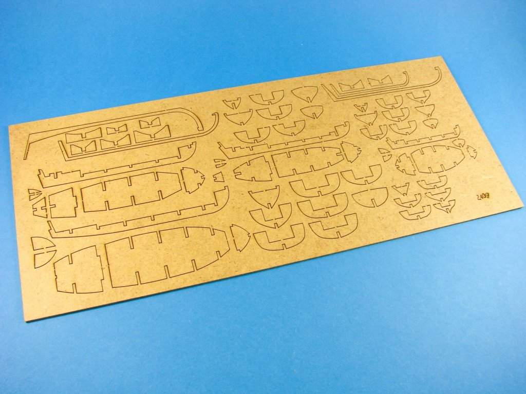
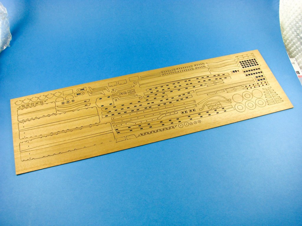
1/72 HMS Vanguard 1787
Victory Models/Amati
Catalogue # 1300/04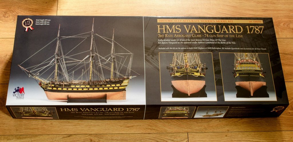
HMS Vanguard was a 74-gun, third-rate ship of the line of the Royal Navy, launched on 6 March 1787 at Deptford. She was the sixth vessel to bear the name. Vanguard was built as an Arrogant Class vessel. Arrogant-class ships of the line were a class of twelve 74-gun third rate ships designed by Sir Thomas Slade for the Royal Navy and were designed as a development of Slade's previous Bellona class, sharing the same basic dimensions. During this period, the original armament was the same across all the ships of the common class, of which the Arrogant-class ships were members. The first of the twelve ships of this class were HMS Arrogant and HMS Cornwall, both completed in April and September of 1761, respectively.
The kit
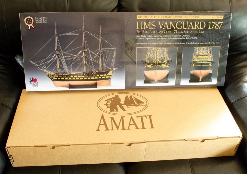
I apologise if we seem a little late to the show with this release, with the kit originally being release around 2007, give or take a year or three.. However, unlike the world of plastic modelling that I usually frequent, these sorts of kits are pretty timeless and stand the test of time far, far better. It’s also a pretty premium product and it really does make sense to be able to see a full review of it before you shell out not an insignificant amount of money on it. There are numerous builds of this online, with a good number on Model Ship World, but there are no actual reviews that I can see anywhere, so I thought I’d try to redress that here. If you order this kit, you really need to make sure that you have bench space for it. Sounds obvious, but this is a very large box and weighs in the region of 14-15kg (30lbs+).

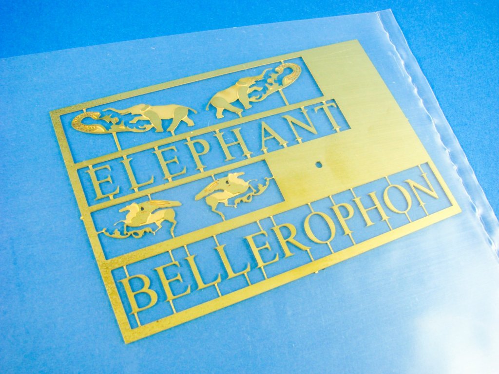
Thankfully, the box is also of a pretty rigid construction to hold all the weight contained therein. Amati/Victory Models’ presentation is flawless with a port side profile of the completed ship on the lid, adjacent to a bow and stern image of the same model. Text says that the model can be finished as either Vanguard, Bellerophon, or Elephant. More colour images adorn the sides, plus some small captures of some of the plans. Lifting the lid off shows that this is merely a decorative lid and the actual corrugated box has a built-in lid that’s locked into place with three large tabs. At least if you sit another kit or two on this one whilst in stash, it shouldn’t crumple under the weight.
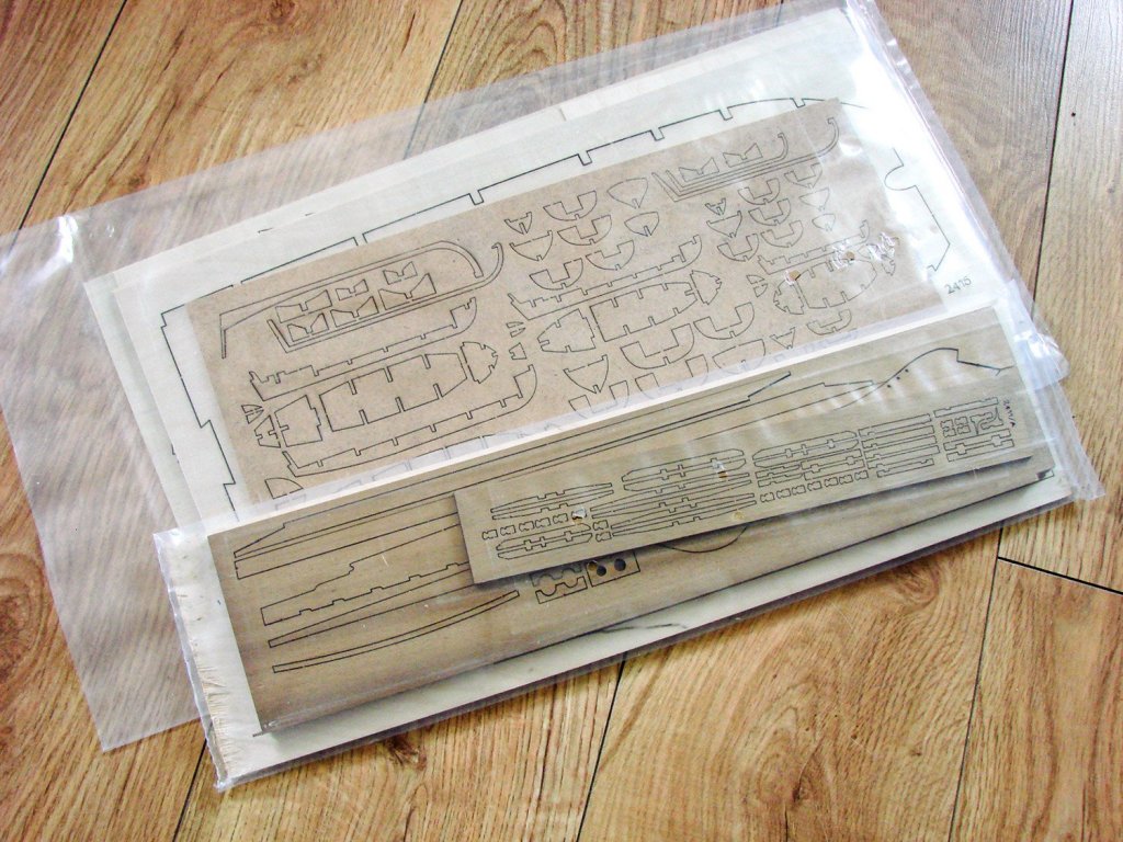

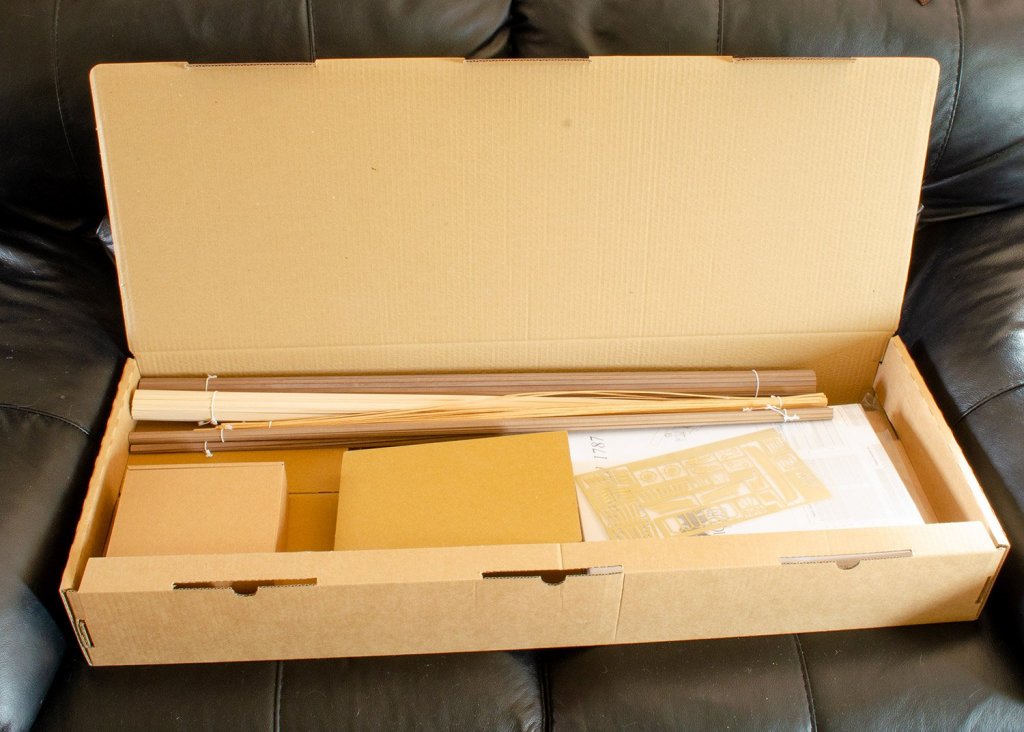
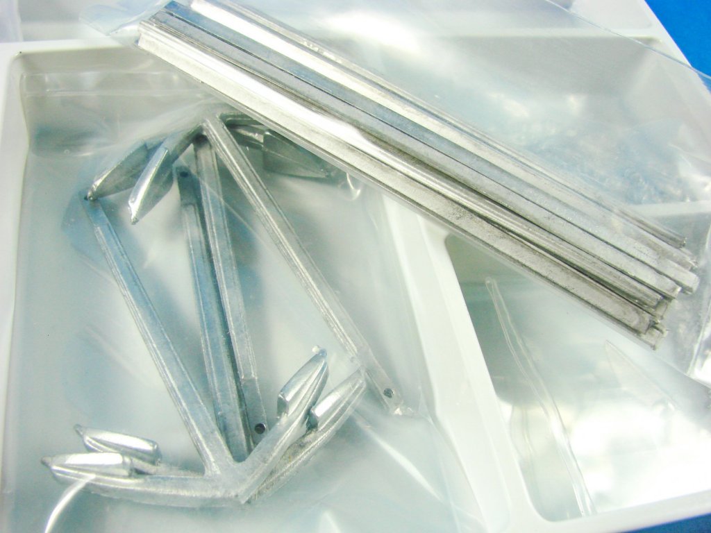
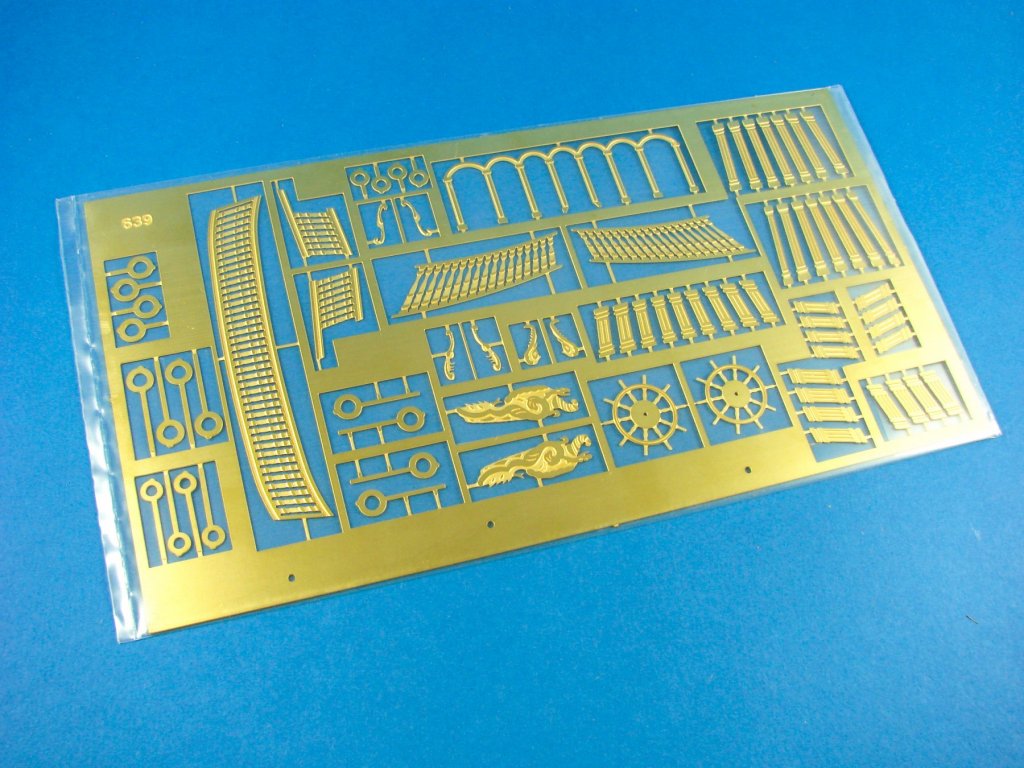
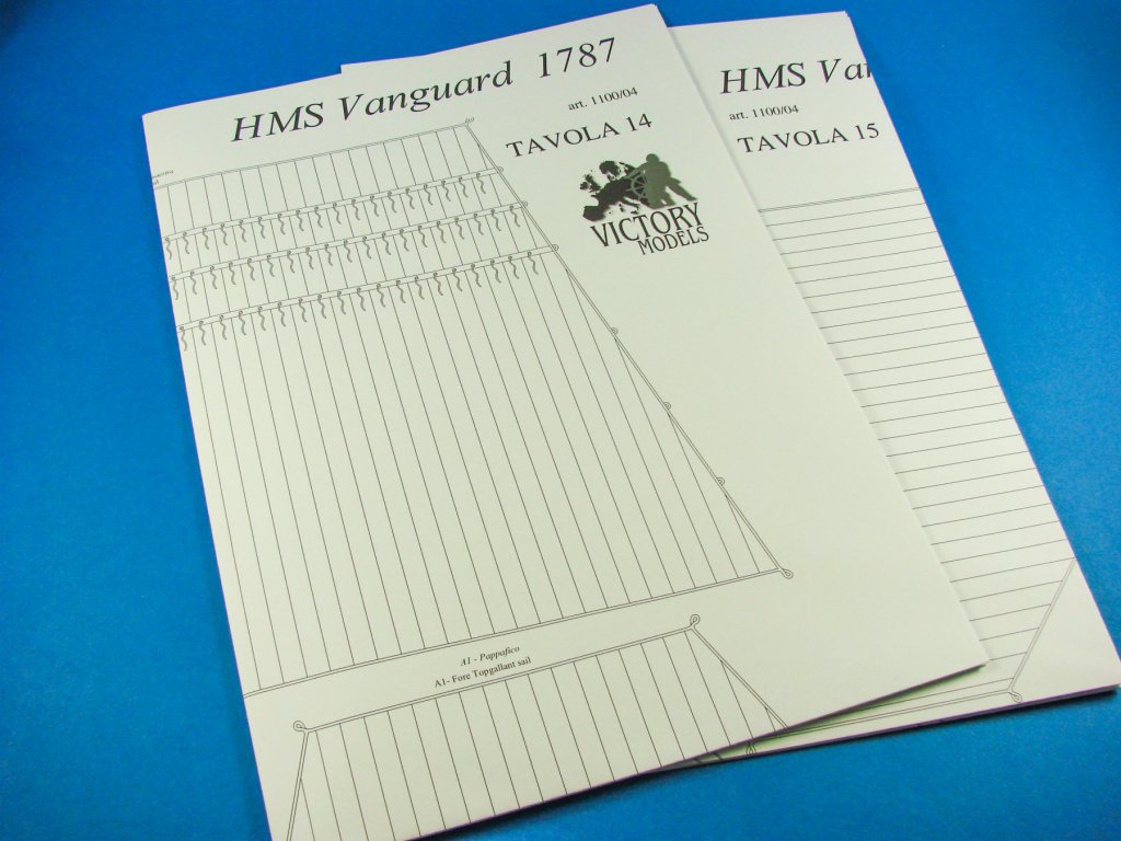
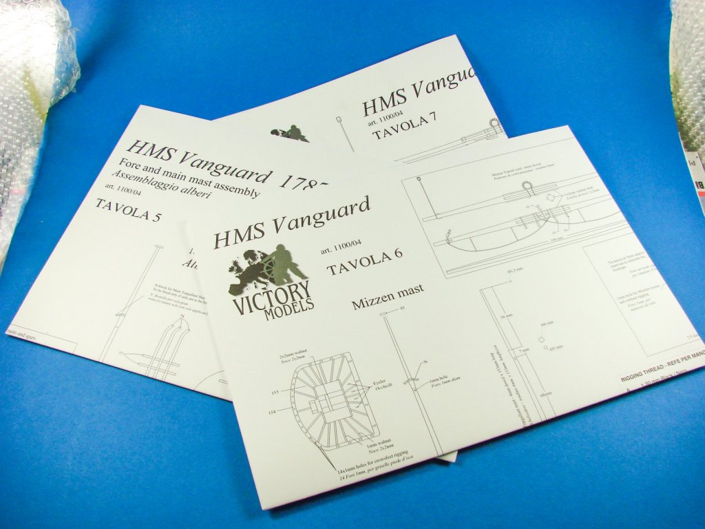
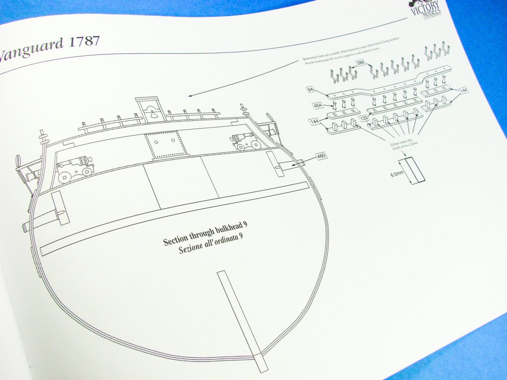
Inside the box we have all of the strip and dowel timber that is bundled together and bound with small lengths of elastic string, three large boxes of components, one smaller box of components, several packs of various flat timbers with laser-cut parts, king-size instruction manual, and a whopping 20-plan pack with a heavy gauge photo-etch fret of embellishments for the stern quarters etc.
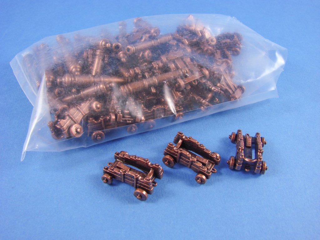

The first and smallest of the boxes I come to contains some thick rope for the anchors, a bag of grating pieces, a sheet of what appears to be thick tin foil, and a large bag of cast metal gun carriages that have an antique finish to them. I find the inclusion of the latter quite a puzzle as kits of this standard would normally have these parts given in timer, which would be my preference. Detail on the carriages is actually quite nice, but they also have staggered sides, and I’m not 100% sure how accurate these would be. I think I’ll replace these when my build begins.

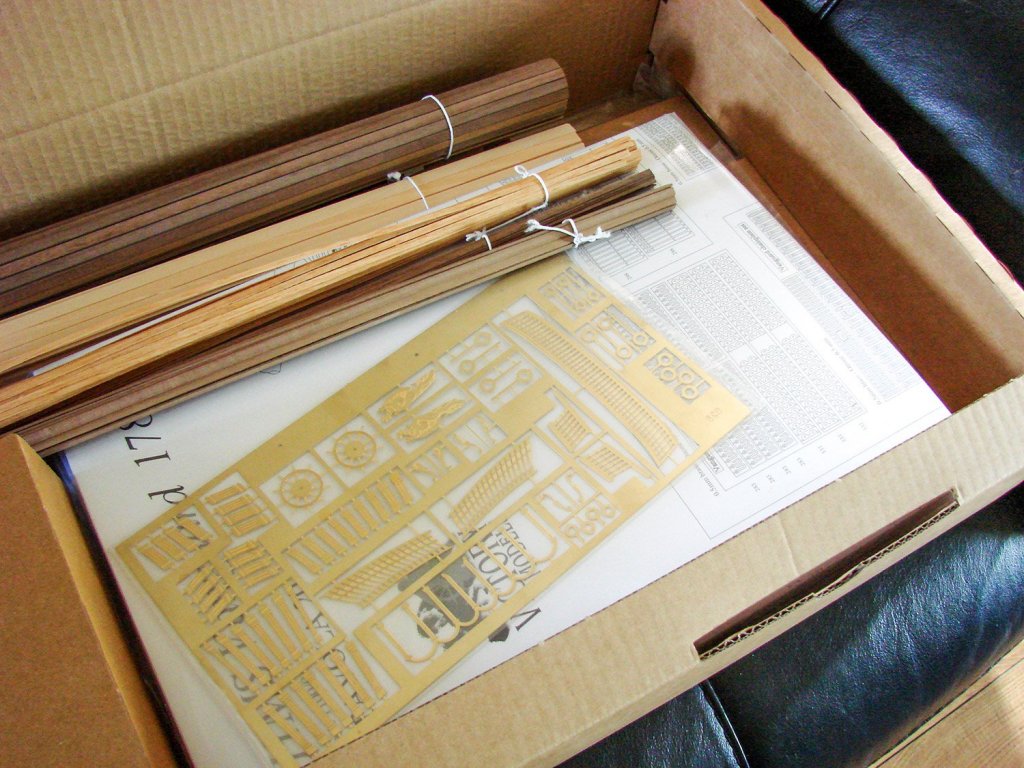
Onto the next box. I know it’s not the done thing, as we say, to add sails to this sort of model, although many do and make a superb job. If you do wish to go down that avenue, then a large piece of sail cloth is included for you, as are two sheets of plans which pertain to adding these. We have two laser-cut pieces of timber in this box, notably with parts for the masts and bitts. I’m sure all will become clearer when it comes time to build this. Of course, there are no parts numbers on any wooden components, and you will need to refer to the five sheets of plans that identify what these elements are numbered as so you may locate them to the construction sequence. ELEVEN sheets of brass photo-etch parts are included too, with everything apart from the stern decoration and quarter details. Notice that the launch oars are provided as photo-etch too, but you may want to replace the oar bodies with something less flat in appearance, such as dowel.


Two sheets have the ships name included, as well as other décor, and the ships stove that will be mostly hidden below deck. These sheets also include the stern and quarter windows, lanterns etc. Many hundreds of parts are included here, such as the cannon port hinges, hammock frames, channel brackets, chain plates, boom irons et al.


If that’s not enough metal for you in this box, then add to that the two packets of copper hull plates that are presented as sheets. These can easily be gently scored and snapped off before fitting. These contain the nail fastening details too. I believe there are around 2500 plates which are needed, and you should, in theory, have some to spare too. Two patterns are included, for port and starboard sides. You’ll need to consult with the plans to determine which is which. A sheet of black paper is also included. At the moment, I’m unsure as to what this is, but I’m thinking it could be something to do with the interior of the rear officer’s quarters. A sheet of acetate is included for the stern windows too.


Our second large box of fittings contains two trays of components. One tray contains some wooden components, deadeyes and rigging blocks, plus some small anchors and carronades. I believe the latter may be for use if you choose to build HMS Elephant as some weaponry was slightly different to Vanguard and Bellerophon.

The next tray is given over exclusively to the many rigging cord spools you’ll need, in various sizes and in two colours. Some rope is also supplied.


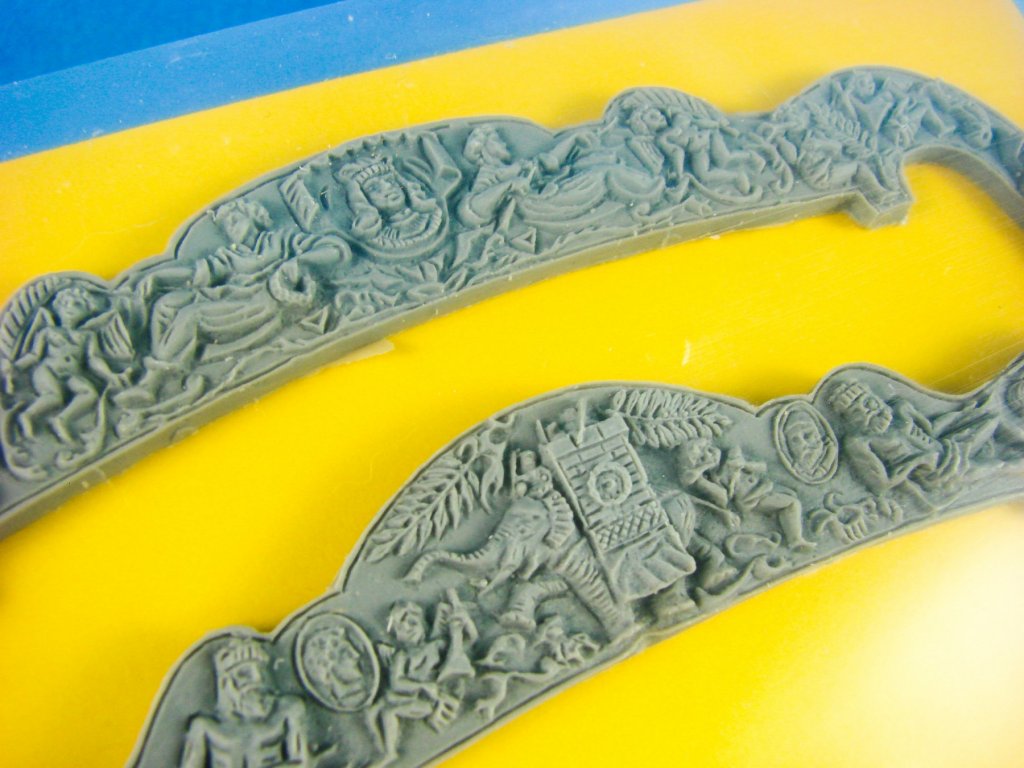
Onto the last box of components. The first tray of parts are all cast white metal, including the figureheads for all three versions of this model, plus some trim, main anchors and the stern decoration for Vanguard, cast in three pieces. Now, whilst Bellerophon is in white metal, Vanguard and Elephant are cast in grey resin and they look spectacular! I believe that initial kits had all of these in white metal but coaxing the parts to fit the curvature of the stern proved tricky, so resin was substituted. Strange that this wasn’t included for all three options though. My original intent was to build Bellerophon, but I think this will now be Elephant because firstly, I haven’t seen one yet done, and secondly, because I can use a resin stern décor and add some amazing colouration to it. Two stern fascias are supplied in this kit, with Vanguard being shallower than that of Elephant and Bellerophon, so as to accommodate the carvings.

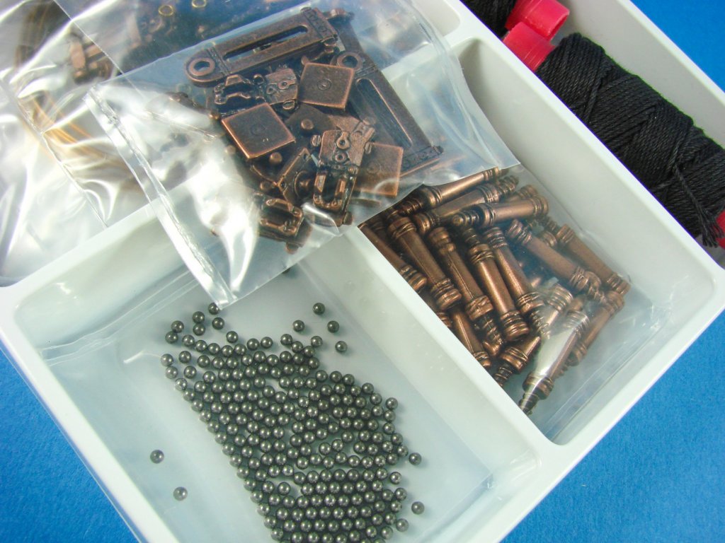
The last tray contains PE parts, more rigging cord, brass nails, brass wire, cannon and gun carriages, cannon shot, and a number of other metal castings. All metal castings here are antique in finish.

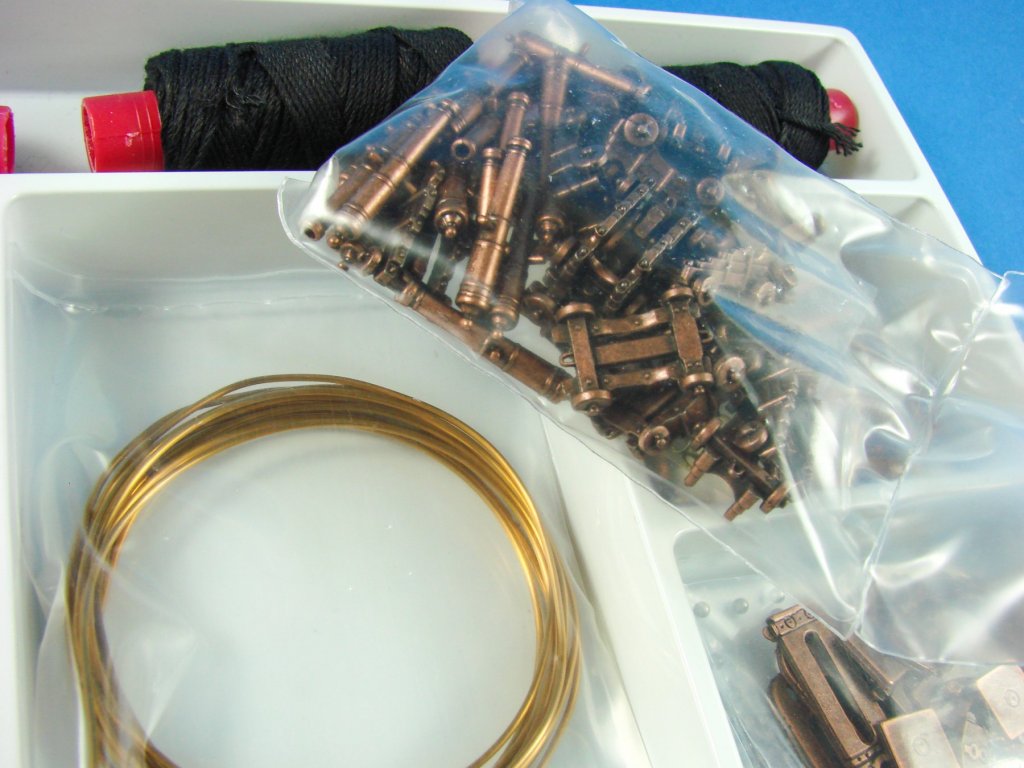
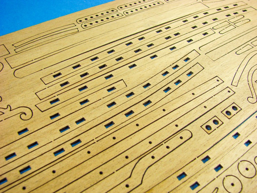
Being a large kit means you need plenty of strip wood stock, especially as this is a double-planked model. First planking timber is lest numerous that second because of the upper bulwarks being supplied as plywood parts. Timber quality is excellent with no stringy or split wood. Bundles are kept together with elastic string. I used a little extra tape on some of the thinner stock, to stop them bulging out in the middle. Various diameters of down are included and of different hues. As these will generally be painted, I think the colour is inconsequential. Again, quality is superb, with no splitting or roughness.


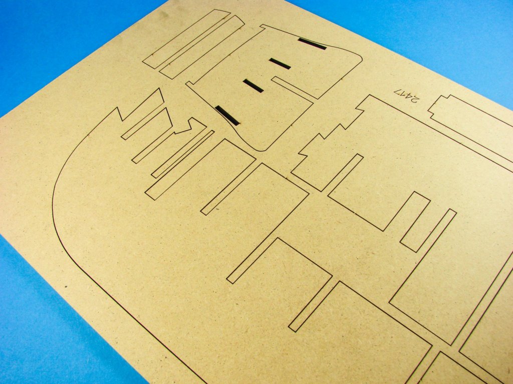
All of the various packages of flat sheet components are stored in thick plastic sleeves, and the first here contains three sheets. One of these is for the various keel parts, plus the rudder. Another of the same material is included with various rigging bitts and anchor stock parts etc. A ply sheet is also included with the strips to mount the false cannon on the lower deck and parts for the stern quarters.

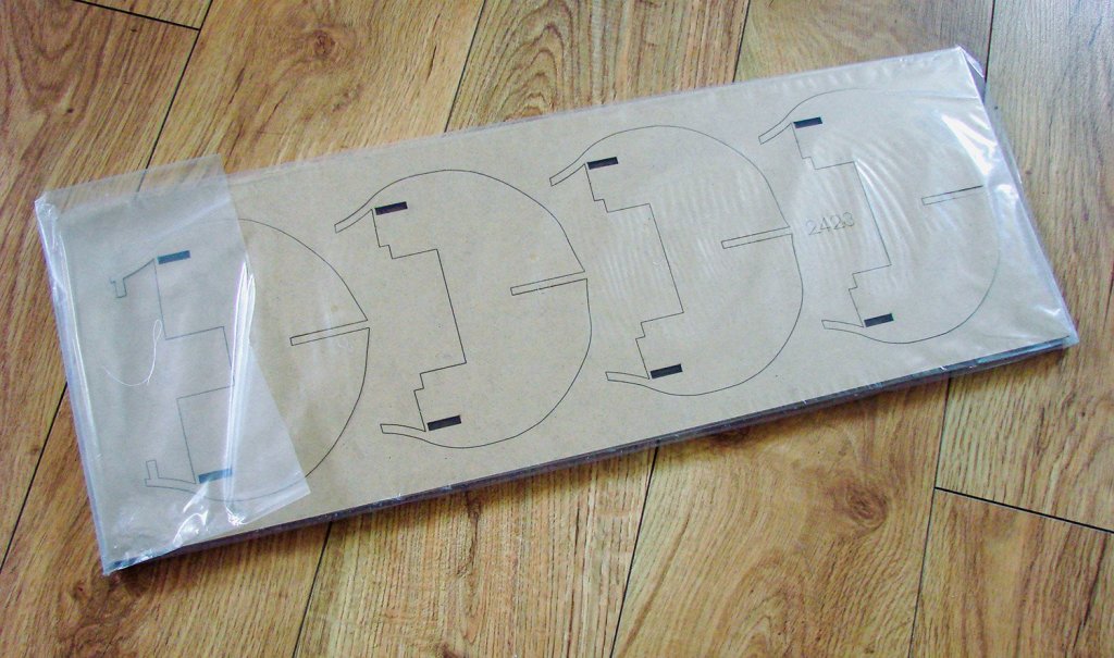
Moving onto the next packet, we are presented with a laser-cut sheet of MDF for the ship’s launches. Here we have the keels and bulkheads for these vessels, all cleanly cut and with minimal effort needed to remove. I’m a little surprised to see this material for this purpose, but the homogenous nature of it is perhaps better suited than plywood and should provide an excellent basis for these miniature builds. More sheets of thin ply provide the main deck components, stern fascias (two options), bow gratings, upper bulwarks with cannon openings, and formers for the quarter galleries.


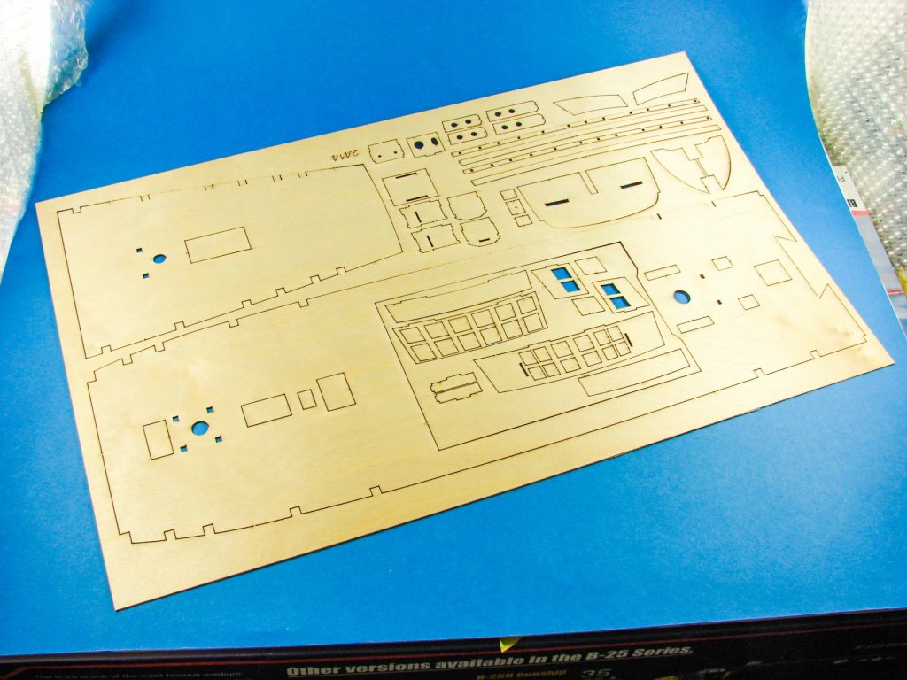
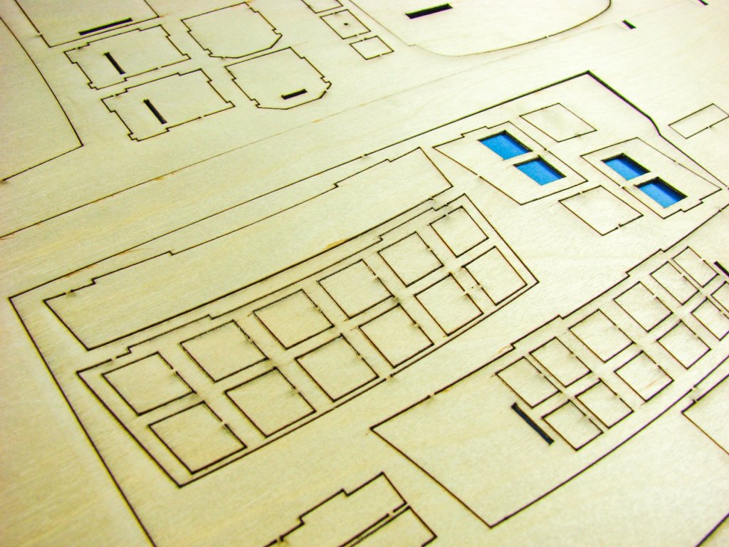
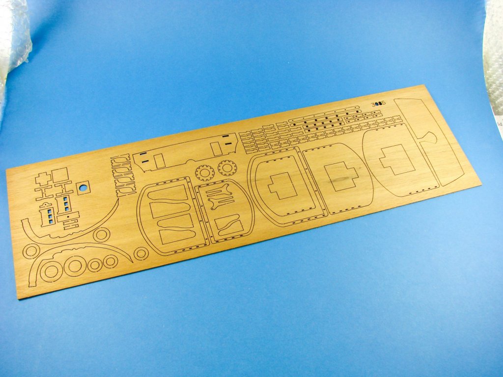
Moving onto heavy material, several sheets of MDF provide all of the ship’s bulkheads, false keel (broken down into two parts) etc. Another sheet of timber contains laser-cut channels, carved mouldings etc. Some of these would benefit from a little carving in themselves to profile them a little better.


Flags? You definitely need them for a ship like this. A set of silk-screen printed flags is included and these appear to have a self-adhesive backing.

Lastly, for parts, we have a relatively thick-gauge photo-etch sheet what holds all the parts for the stern and quarter decorations, including railings, arches and other ornamentation. Under a coat of primer and paint, these look very good in place, as seen on numerous building logs on Model Ship World.

When it comes to paperwork, this kit won’t leave you wanting. Inside the box, as well as a large assembly manual, is that pack of 20 plans. Most of these are A1 in size with one plan being a whopping A0, so make sure you have some wall space to mount it to for reference. Out of these plans, 5 provide parts maps and identification for the materials supplied, 2 plans deal with the optional sails, at least three deal with rigging Vanguard, 3 concern masting, and the rest for the hull and details etc.
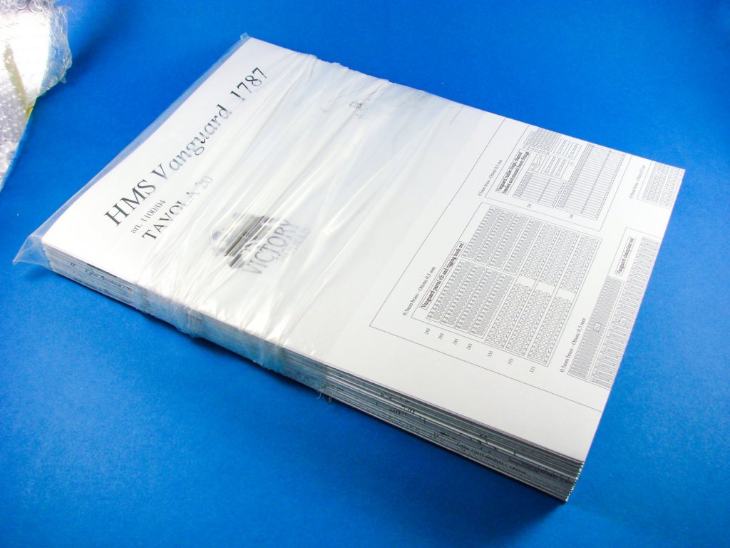
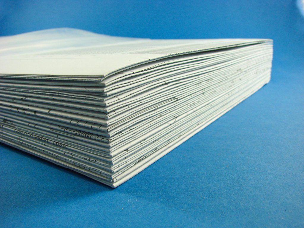

Two building instruction books are supplied. The first one deals with the main areas of construction using line drawings and text. This is quite a large book and has 32 pages. Accompanying this is a smaller A4 book of 20 pages which is generally text-driven and deals with construction in more detail, plus finishing etc. Some very nice history of Vanguard, Bellerophon and Elephant is included.


Conclusion
It must be 10 to 12 years since this kit first hit the shelves, and here we are a decade or more on, and I finally get to take a glimpse at Chris Watton’s masterpiece. I remember him designing this at the time and saw a few online photos, and I have to say that the contents of this kit are pretty much what I expected, save for the inclusion of the cast gun carriages. I really like the inclusion of MDF for the main structure (bulkheads, horizontal former and false keel) as this has almost zero tendency to warp. Indeed, mine are die-straight and will form the basis of an accurate and trouble-free build. All timber stock is first rate (for this third-rate ship!), and fixtures and fittings are high quality. Having the upper bulwarks as pre-cut parts with their jigsaw fit and pre-cut cannon port is also a time saver and a big help in ensuring that all guns will mount in their correct place and the correct height/elevation.A comprehensive plan pack ensures that every constructional angle is covered, and with 20 plans, Amati haven’t cut any corners. This isn’t a beginner’s model, and I’m sure you’ve heard that phrase many times before, but in this case, you really must have a number of builds under your belt and be able to exercise a degree of project management and prerequisite modelling skills to cater to and overcome the challenges that a complex model like this will demand. In all, a super kit of a formidable class of ship and with all the bells and whistles to build any of three vessels. You can’t do better than that!
My sincere thanks to Amati for sending this kit for reviewing on Large Scale Modeller. To purchase directly, check out your local Amati model stockist or online Amati retailer.

-
1
-
-
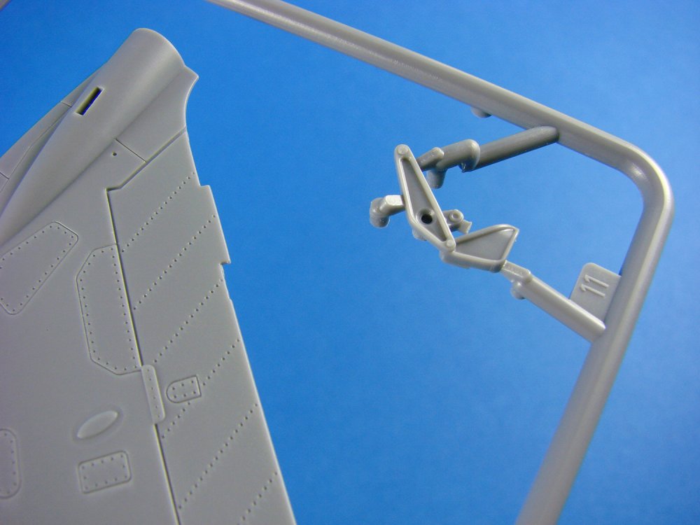
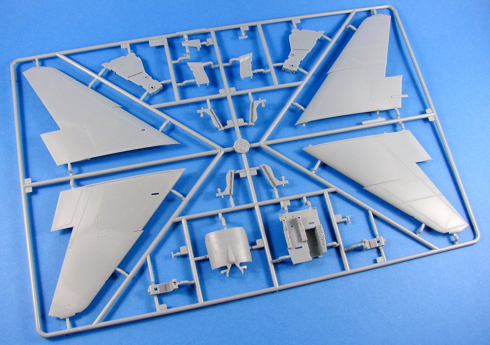
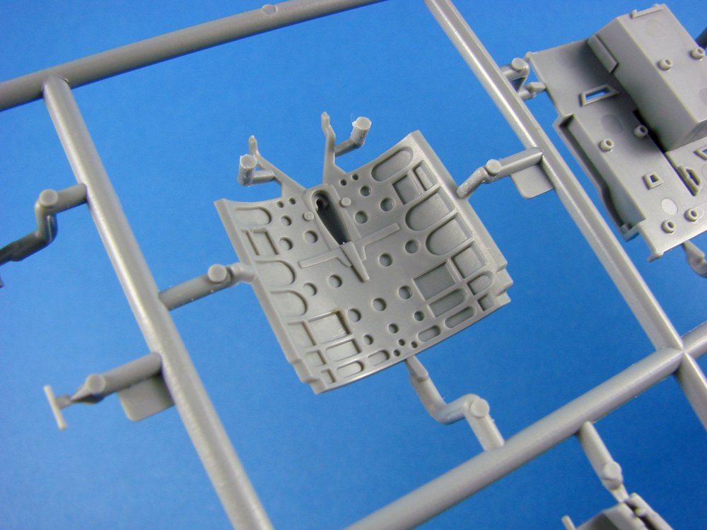
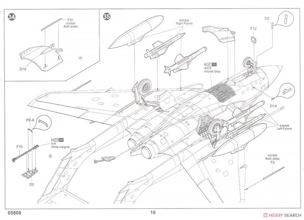
1/48 de Havilland DH.110 Sea Vixen FAW.2
Trumpeter
Catalogue # 05808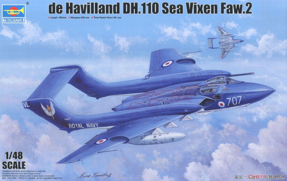
The de Havilland DH.110 Sea Vixen is a British twin-engine, twin boom-tailed, two-seat jet fighter flown by the Royal Navy's Fleet Air Arm during the 1950s through the early 1970s. The Sea Vixen was designed by the de Havilland Aircraft Company during the late 1940s at its aircraft factory in Hatfield, Hertfordshire. It was developed from an earlier first-generation jet fighter, and the Sea Vixen was a carrier-based fleet air-defence fighter that served into the 1970s. Initially produced by de Havilland, it was later called the Hawker Siddeley Sea Vixen after the de Havilland Company was absorbed by the Hawker Siddeley Corporation in the year 1960. The Sea Vixen had the distinction of being the first British two-seat combat aircraft to achieve supersonic speed, albeit not in level flight. Operating from British aircraft carriers, it was used in combat over Tanganyika and over Yemen during the Aden Emergency. In 1972, the Sea Vixen was phased out in favour of the American-made McDonnell Douglas Phantom FG.1 interceptor. Only one Sea Vixen remains airworthy today in the world and is displayed regularly at air shows. The Sea Vixen also flew in an aerobatic role, performing in two Royal Navy display teams: Simon's Sircus and Fred's Five.
Of the 145 Sea Vixens constructed, 55 were lost in accidents. Two DH.110 development prototypes were also lost. The 55 Sea Vixens lost represented a loss rate of almost 38%. 30 (54%) of these were fatal incidents, 21 of which involved the death of both pilot and observer. A small number of Sea Vixens were sent to FR Aviation at Tarrant Rushton airfield for conversion to D.3 drone standard, with some undergoing testing at RAF Llanbedr before the drone programme was abandoned. Among them was XP924, now G-CVIX, the only Sea Vixen to remain in flying condition, which has now been returned to 899 NAS colours. Formerly owned and operated by De Havilland Aviation, G-CVIX could be viewed at their hangar at Bournemouth Airport in Dorset, southern England, or at air shows around the UK.
Extract courtesy of WikipediaThe kit
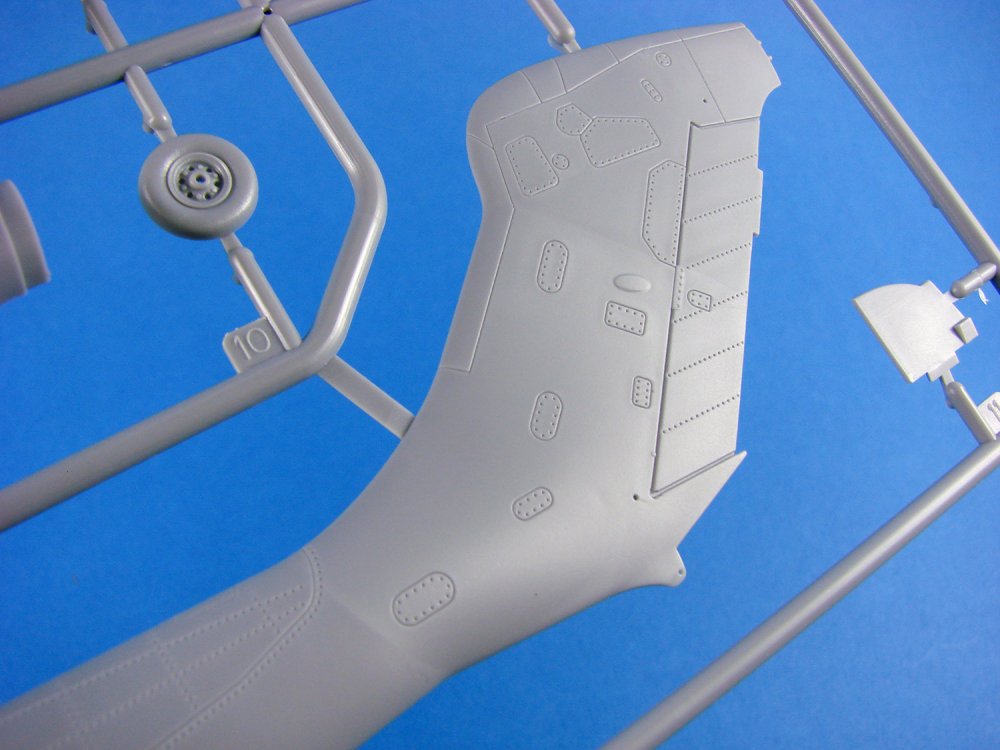
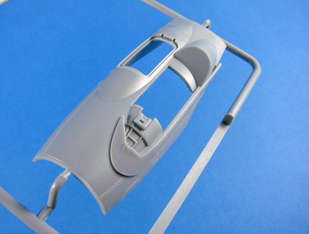
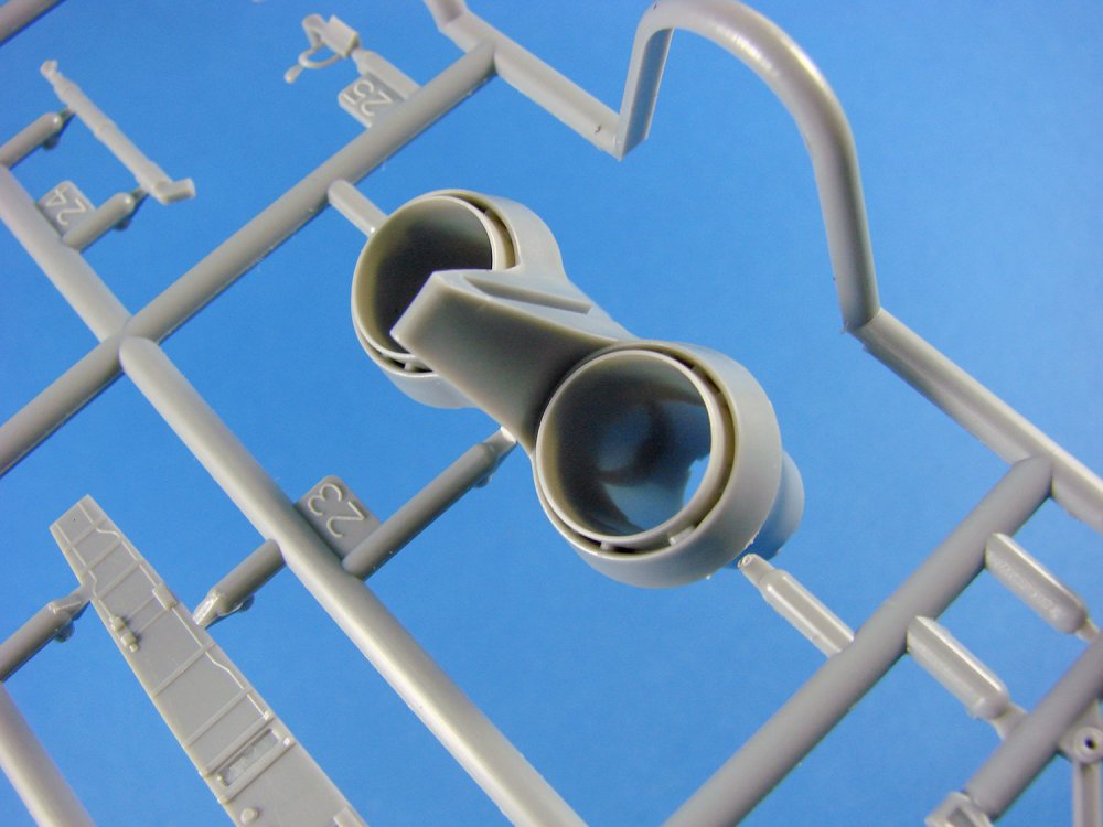
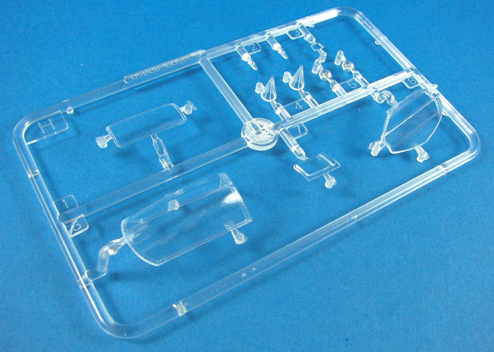
I really can’t understand Airfix. All I can presume is that sales of their rather nice Sea Vixen didn’t merit it continuing in production, or it could simply be that it wasn’t scheduled into their production schedules with their current batch of new releases. Either way, until Trumpeter released this particular kit, you would really need to scrabble around to try to source the Airfix release, and probably get scalped in the process. But, thankfully, Trumpeter comes to the rescue with a brand-new tooling of this aircraft, and in the same version as the hard-to-find Airfix kit. All is good, yes? Well, maybe… Whilst my review looks at the kit from an in-box perspective, it is pretty apparent from eyeballing the kit and also gleaning information from online sources, that Trumpeter’s B-Team have been busy once again and got dirty in the process. I’ll mention the differences and possible discrepancies with the shapes as I look at the sprues. Each sprue us individually bagged, and a number of components are placed in a separate compartment within the box. These are the nosecone and intakes, clear parts (also wrapped in foam), and a PE fret.Fuselage upper half
Off to a reasonably good start here with this superbly moulded upper panel that spans the area up to where the wings would fold. This is neatly keyed to accept the tabs on the tail boom halves, and also exhibits some very nice panel line details. The only rivets are those that follow the panel lines. If anything, both panel line and rivet detail is perhaps a little too heavy, but this can easily be lessened with a coat of Mr Surfacer and rubbed down before prime/paint. Internally, some stiffening webs are moulded to lessen the compression effect that could arise during handling and construction. A small number of nubs exist on the upper surface, from the moulding process, and these will be very simple to eliminate. These are where the moulding sprue will have been before they removed it. With my reference, a number of panel shapes look wrong too and Trump has simply used the rivet depiction to replace the various shapes and style of fasteners that exist here.

Fuselage lower half
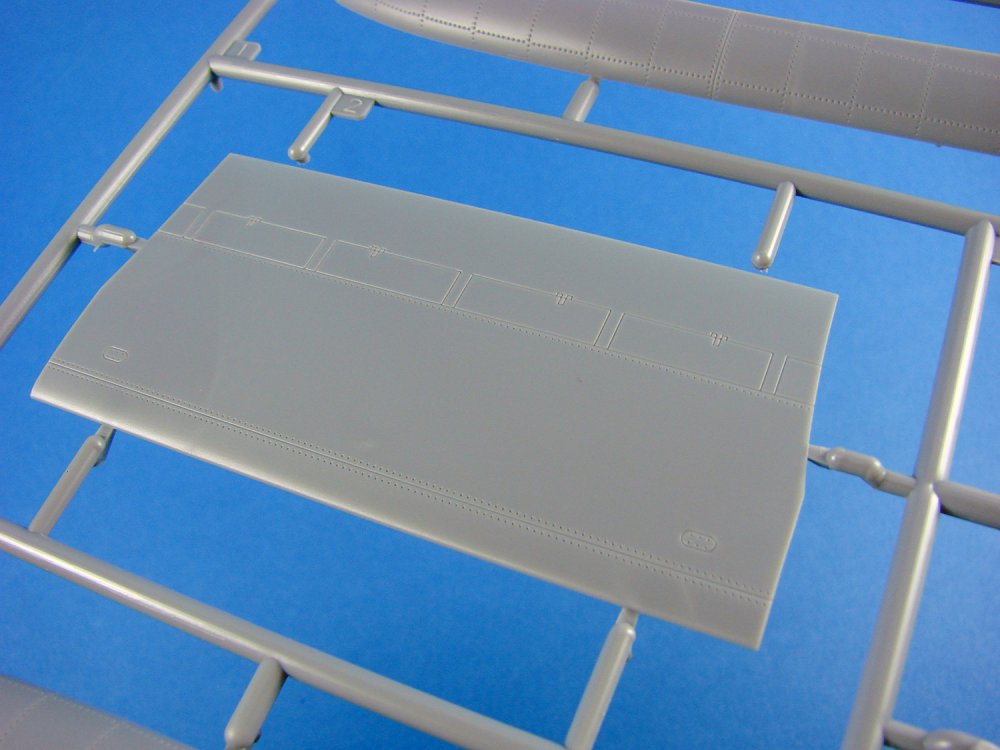
Following in the same style as the upper panel, this lower part, incorporating the lower nose and gear bay openings, has the same style of surface textures which I think need reducing a little. Openings are moulded to accept the separate wheel bay installations, and a large airbrake section is included with all internal details. Here, and on the wing surface, you will need to remove those very minimal nubs. As for the airbrake housing detail, I would say this is pretty reasonable, complete with the various structures and pressure tanks.


Sprue B
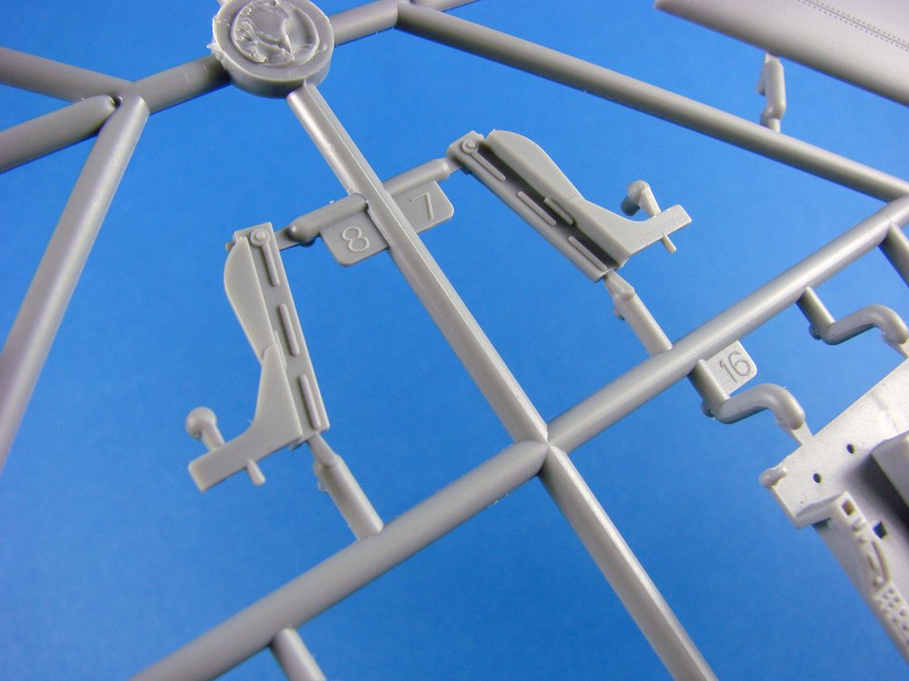
Here we have the external halves for the the tail booms. Here is where we see some discrepancies from both the Airfix release (which is generally taken to be pretty accurate as far as shapes go), and also from reference I have. It does appear that the booms are slightly too long aft of the wing trailing edge, but more frustratingly, the top of the fin appears to be more bulbous than it should be. I do think this can be fixed with a little sawing and putty though, but nonetheless, Trump got this wrong. The booms seem to be almost devoid of any panel line details too.
Whereas Airfix moulded their stabiliser with a separate elevator, this kit is provided with the parts combined. I have to say that it makes the Trump effort look like the whole stab and elevator is a single unit with no real differentiation in the areas. A few swiped of a scriber to deepen the panel line that separates them would be needed.

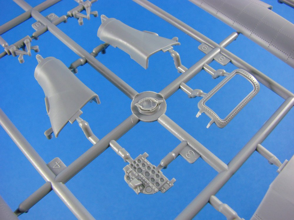
Other parts here include the two-part nose wheel with integral hubs (no weighted effect), cockpit bulkhead and upper halves of the intake channels.
Sprue C

This sprue contains the inboard halves for the tail booms, plus the upper stabiliser section, nose wheel fork half, and intake lower halves. Trumpeter has moulded a great little instrument panel for the pilot, with blank, recessed gauges that can be supplemented by the kit decals (or better, Airascale instrument decals). Something else which looks a little anomalous, perhaps, is the navigator hatch. Compared with the Airfix kit, and with my own and online searches, the hatch appears to be narrower than it should be, and perhaps a tad longer too. The part itself is nicely detailed with rivets running around its circumference.
The lower portions of the main gear struts are moulded here too, and these look rather good.
Sprue D
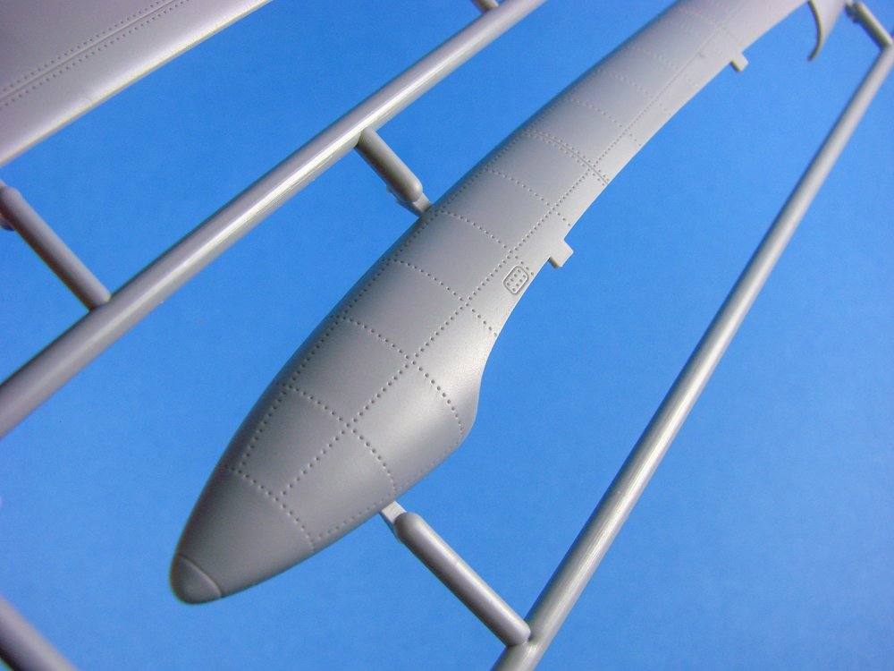
Both wings have their outboard panels moulded here, as traditional upper and lower halves. Ailerons are separate, as are the wing fences which are supplied as photo-etch parts. Again, the only rivet details to be seen are those outlining the various panel lines. Even the panel lines on these parts aren’t too numerous and looks pretty good.

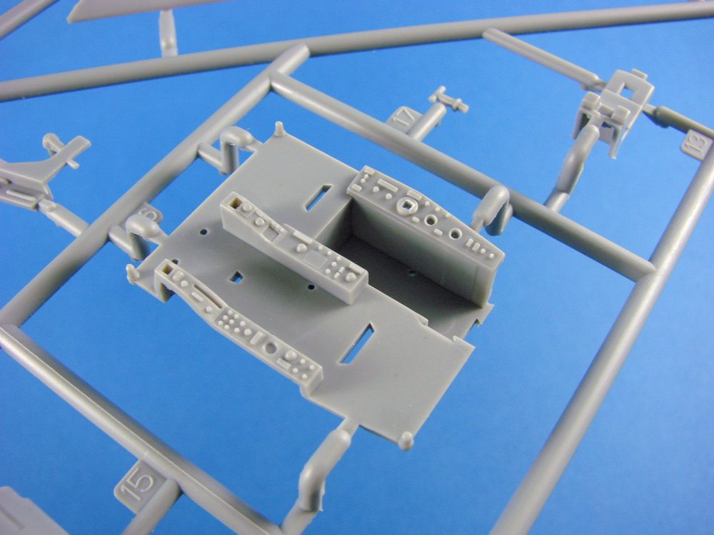
You will also find the cockpit tub here, and whilst similar in many respects to the Airfix kit, the consoles themselves look more simplified and even a different shape. The starboard pilot console appears to be narrower than it should be, so some work will be required here to fix that. Maybe Eduard will come up with something that should at least improve these rather lacking areas. Crew seats are also very disappointing in their amazingly basic details. Again, maybe look for something aftermarket to replace these entirely.
I have to say that I much prefer how Trumpeter has created the wheel bays on this model, in comparison to Airfix’s release. On the latter, these are all-in-one mouldings, but this kit has separate side ceilings with more detail, and also detailed side walls. A much nicer representation indeed. As for the speed brake itself, this is very similar to the Airfix kit, and indeed very close to the real thing.
Sprue E

The key player here is the upper nose section of the Sea Vixen, with both cockpit openings. This is a very nicely executed moulding with some slide-mould tech used to create it. That heavy fairing to the front of the windscreen is beautifully recreated, but you will also note the navigator’s opening which does appear to be too narrow and long. You may notice something else that’s really frustrating too, and that’s the solid rear portion of the pilot’s canopy is moulded here too meaning you CAN’T position the hood in an open position. Just what was Trumpeter thinking about here? For many, that will be a deal-breaker.

More slide moulding is employed for the tail pipes, and this part includes a portion of the exhaust tube on the interior. The edges of the external tube are nice and thin and sit recessed within the rear fuselage portion. Very nicely recreated. Parts are included for what appears to be the wing rib detail for a wing-fold build, but these aren’t shown in the kit instructions.


Other parts here include the upper portion of the main gear wells, main gear exterior door parts (these have separate interior parts as seen on Sprue F), nose gear strut and ailerons that are constructed from upper and lower halves. The trailing edges of these look reasonably thin too.
Sprue F
In this day and age, I really would like to see companies create weighted effect tires. As well as this omission, the hubs are also very simplified and missing many key details. I sense the need for more aftermarket. The main gear interior door parts are found here, and these look excellent. Main gear well and nose gear well components can be found on this sprue, as can the intake fan parts and weapons pylons. A number of other cockpit parts are included, such as rudder pedals and navigators panel.


Sprue G
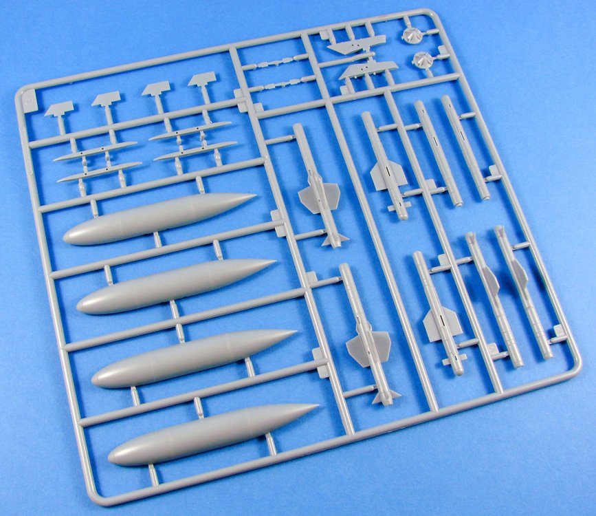
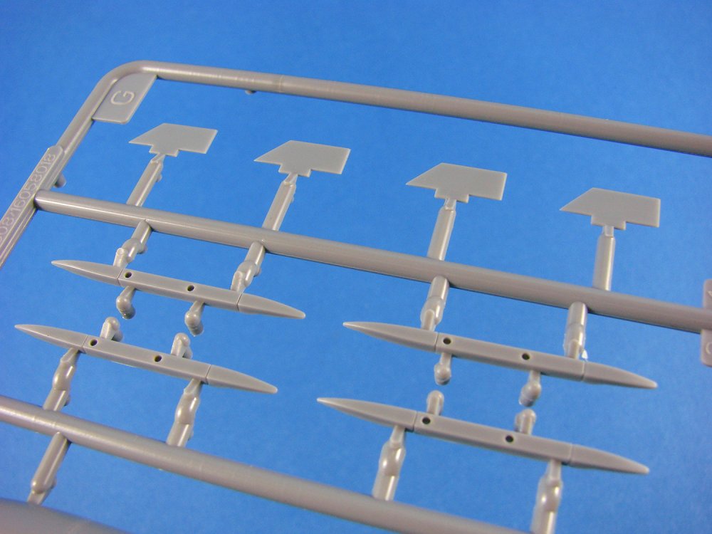
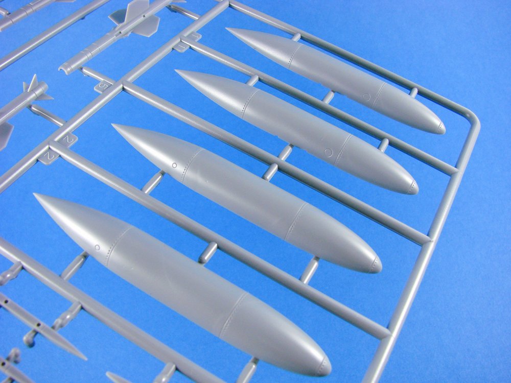
This is the weapons and stores sprue with provision to build two external fuel tanks, and four missiles. Missiles have clear nose parts included, and overall detail is very good. It’s a strange sprue to find the exhaust flame holders, but here they are!


Sprue H
Trumpeter’s clear parts are always superb and come wrapped in an extra sleeve of foam to protect them further. Frame lines are nicely defined, and the parts are bright, with excellent clarity. As you can see from this photo, the main hood isn’t designed to be posed open, as previously mentioned, and that is, for me, probably the killer blow amongst the various other issues.
Separate parts
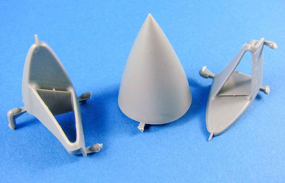
Three parts are included in a separate bag. These are the nose cone and the single-piece intake fairings. More slide-moulding has been used here and the parts look very good. Only minimal clean-up is required to remove the sprue tabs. A sanding sponge will also be needed to remove he slightly fuzzy edges on the intake itself.
Photo Etch

A single fret includes parts for the wing gates, airbrake housing bay bulkheads and intake vanes. Production is excellent with small tags holding the parts in situ.
Decals

A single sheet of nicely printed decals is included. Printing is glossy, suitably thin and with minimal carrier film. Registration also appears to be correct. Instrument decals are included, but alas, no stencils.


The three schemes are:
- FAW-2. Unit: 766 NAS, FAA. Serial 707/VL (XN647), RNAS Yeovilton, 1969
- FAW-2. Unit: 890 NAS, FAA. Serial 127/E (XJ565)
- FAW-1. Unit: 893 NAS, FAA. Serial 464/C (XN654), HMS Centaur, 1964


Instructions
I’ve always liked Trumpeter’s instructions. They are clear, non-ambiguous or fussy, and usually logical in approach. Construction is broken down into 35 stages in a manual that spans 18 pages. Come colour reference is supplied during the build.
A colour sheet is included, highlighting the three schemes, with good scheme depiction and paint call-outs, plus decal placement. Other paint codes are supplied for Vallejo, Model Master, Tamiya and Humbrol. I could be wrong here, but the instructions show the undersides as being in silver (specifically Gunze N8), but I am sure these aircraft were white underneath. That could be a problem as the supplied underside codes are also printed in white, so you would need to get a set of more accurate markings that were correctly provided in black.
Conclusion
Another mixed bag from the house of Trumpeter. I can’t understand why they get things so wrong. There’s plenty of information out there to use as reference. We have shape and size issues with various elements of the airframe, and that lack of option for posing the cockpit in an open position. You’re going to need new cockpit elements, plus seats, wheels etc. to bring this anywhere close to the correct level of detail you’ll require. Then there’s filling the panel lines that are wrong and re-scribing them. You will need new serial decals too. Add to that the tail boom and fin issues, and your work will be cut out. In the meantime, we can all just pray that Airfix re-release their infinitely better kit, and this one can be castigated to the bin of curios and oddities.My sincere thanks to Pocketbond for sending out this sample for review here on LSM. To purchase, check your favourite online retailer or Trumpeter specialist.

-
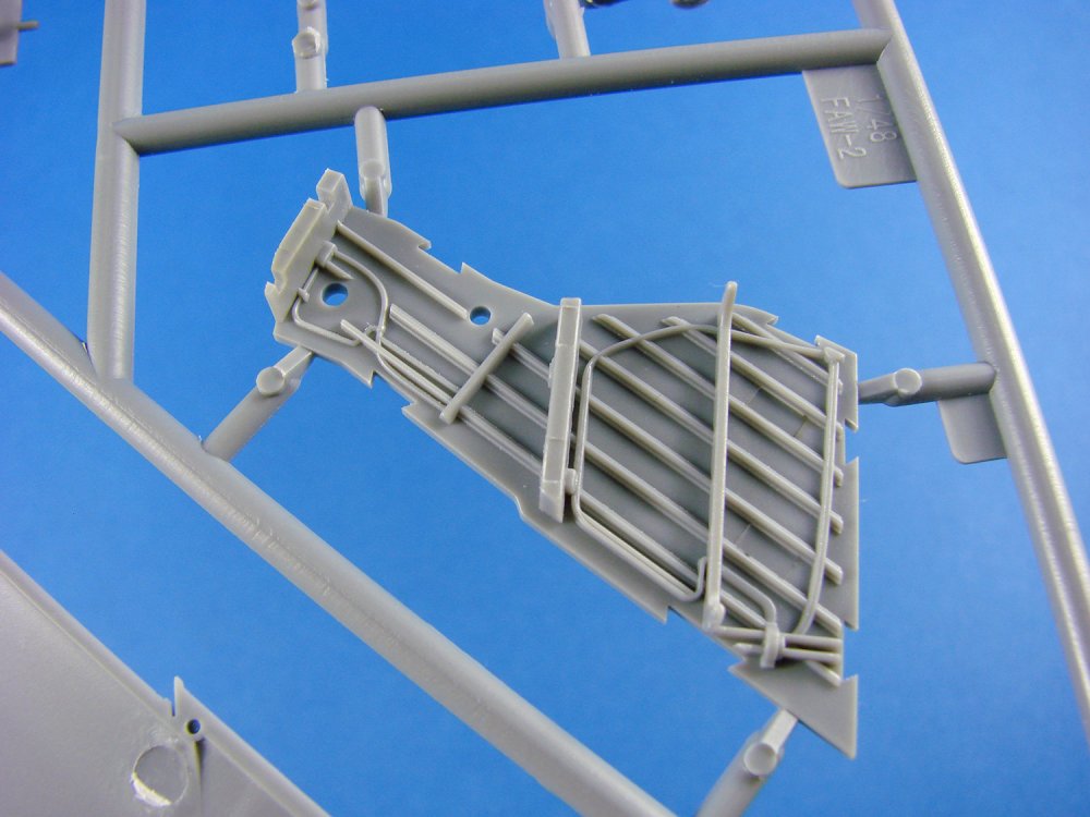
1:48 Fairey Firefly Mk.1
Trumpeter
Catalogue # 05810
The Fairey Firefly was a British Second World War-era carrier-borne fighter aircraft and anti-submarine aircraft of the Fleet Air Arm (FAA). Designed to the contemporary FAA concept of a two-seat fleet reconnaissance/fighter, the pilot and navigator/weapons officer were housed in separate stations. It was superior in performance and firepower to its predecessor, the Fulmar, but entered operational service only towards the end of the war when it was no longer competitive as a fighter. The limitations of a single engine in a heavy airframe reduced its performance, but it proved to be sturdy, long-ranged, and docile in carrier operations. The primary variant of the aircraft used during the Second World War was the Mk I, which was used in all theatres of operation. In March 1943, the first Firefly Mk Is were delivered but they did not enter operational service until July 1944 when they equipped 1770 Naval Air Squadron aboard HMS Indefatigable. The first operations were in Europe where Fireflies carried out armed reconnaissance flights and anti-shipping strikes along the Norwegian coast. Fireflies also provided air cover during strikes on the German battleship Tirpitz in 1944.
The Fairey Firefly served as a fleet fighter but in post-war service, although it was superseded by more modern jet aircraft, the Firefly was adapted for other roles, including strike operations and anti-submarine warfare, remaining a mainstay of the FAA until the mid-1950s. UK and Australian Fireflies flew ground attack operations off various aircraft carriers in the Korean War. In foreign service, the type was in operation with the naval air arms of Australia, Canada, India and the Netherlands whose Fireflies carried out a few attack sorties as late as 1962 in Dutch New Guinea. Throughout its operational career, the Firefly took on increasingly demanding roles from fighter to anti-submarine warfare stationed mainly with the British Pacific Fleet in the Far East and Pacific theatres. Fireflies carried out attacks on oil refineries and airfields and gained renown when they became the first British-designed and -built aircraft to overfly Tokyo.
Extract from WikipediaThe kit
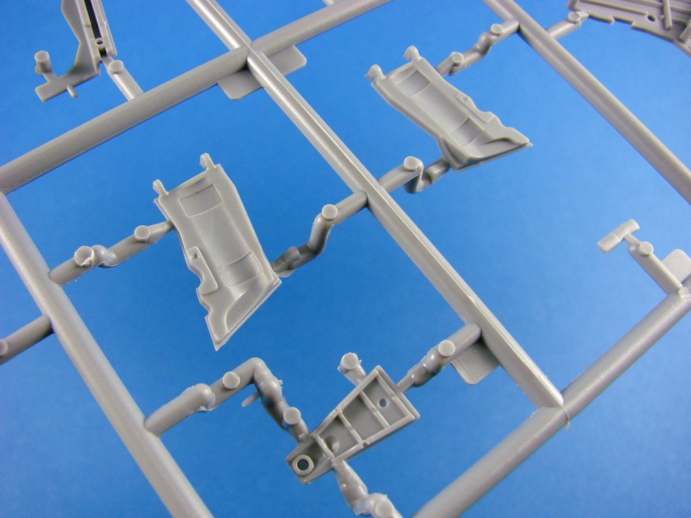
This is a 2018 new-tool kit of this rather strange and awkward-looking fighter aircraft, and I’m actually quite pleased to see it, being a fan of the odd and esoteric. Of course, the new Trumpeter release isn’t the first Firefly in 1/48, with the Grand Phoenix/AZ Model kit being around in some form for the last 17yrs. There is also the extensive range of Special Hobby kits which show the Firefly in numerous marques. I have to say that I would’ve liked one of the AZ Model release with their beautiful resin interior and gear bay sets, but never got the opportunity to pick one up. I was pretty pleased when this Trumpeter kit was sent out for me to look through and interested to see how a modern tool of this aircraft would stand up to scrutiny.Trumpeter’s new Fairey Firefly Mk.1 comes in a fairly shallow box that is stuffed full of plastic. In total, there are SIX sprues of light grey styrene and one of clear parts. Apart from a sprue of which two are supplied, all sprues are packed individually into clear, heat-sealed sleeves. The clear parts have some extra protection by being wrapped in a piece of foam. A single PE fret is included, a large decal sheet, and of course the instruction manual.
The kit itself is listed by Trumpeter as thus:
Model Brief:Length: 236.5mm Wingspan: 282mm
Total Parts: 100+
Photo Etched Parts: 1 piece
Total Sprues 7 sprues
Released Date: 2018-02
More Features: The kit consists of over 100 parts - fuselage & wing with finely engraved panel linesSprue A
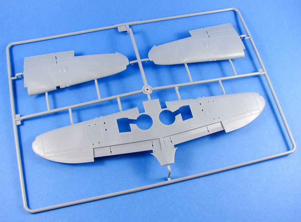
The size of the Firefly becomes apparent when you see the size of the full span wing. This model is almost 12 inches across, which for a 1/48 WW2 fighter, is no shrinking violet. The upper wing panels are moulded as traditional port and starboard parts. Looking at the parts, you’ll immediately notice that the ailerons are moulded as one with the lower wing, with the upper panels being cut-out to accommodate the separate upper aileron half. Whilst this should look perfectly good from above, there isn’t much in the way of demarcation from below, so running a scriber over this area to deepen the panel line, should improve things massively. Trumpeter has made the landing flap as separate parts, with this area having no detail within, as per my references. Surface textures feature finely engraved panel lines, access panels, and key lines of rivets and fasteners, but not too much as to ruin the appearance. Inside the upper wing panels, a stiffening web is moulded to reduce and lateral flexibility in the assembled wing. A wing leading edge lens will be fitted from the clear sprue, and the gun barrels are also separate items.


Sprue B
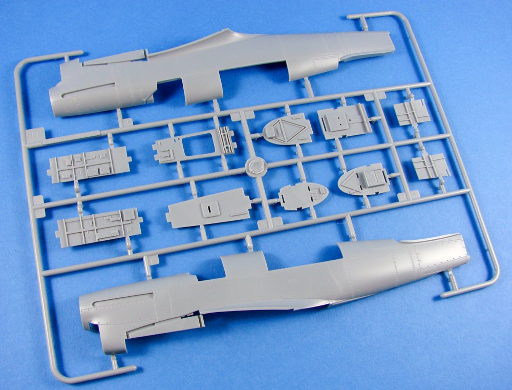
Here, the main parts are for the fuselage, moulded full length, but minus the vertical fin which will be added later in construction, along with the rudder. Again, surface details and textures are actually very good, with some nice cowl fastener details on the nose. The cowl intake is moulded as a separate piece with integral sloping channel, and this will be augmented by the inclusion of some PE grilles. No detail is included within the fuselage as the cockpit are built from separate crew tubs.
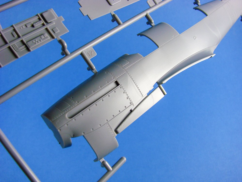
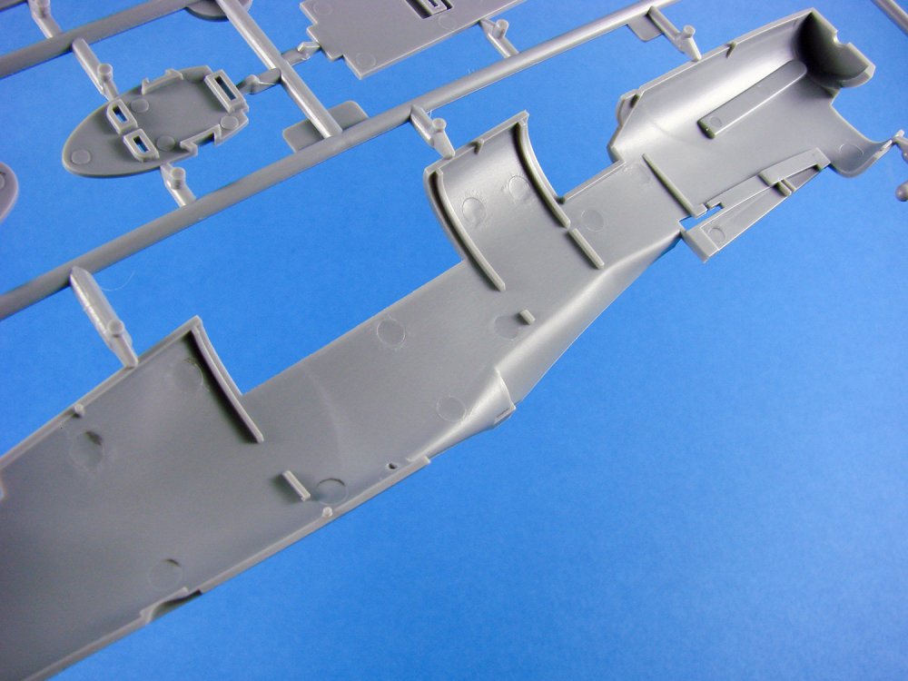
I’m perhaps a little disappointed at the apparent simplicity of the cockpit itself, especially in comparison with the AZ Models resin parts, and even the Special Hobby releases. Checked against reference, Trumpeter has created quite a rudimentary interior which will need to be improved somewhat for it to pass muster. Simple side wall and bulkhead details are included, such as formers and stringers, plus wiring and avionics, but they all look rather sparse. I know Eduard will be releasing some sets for this kit, so I’m hoping that they manage to create some visually interesting stuff in this area.
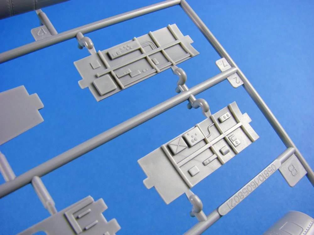
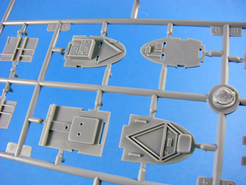
Sprue C
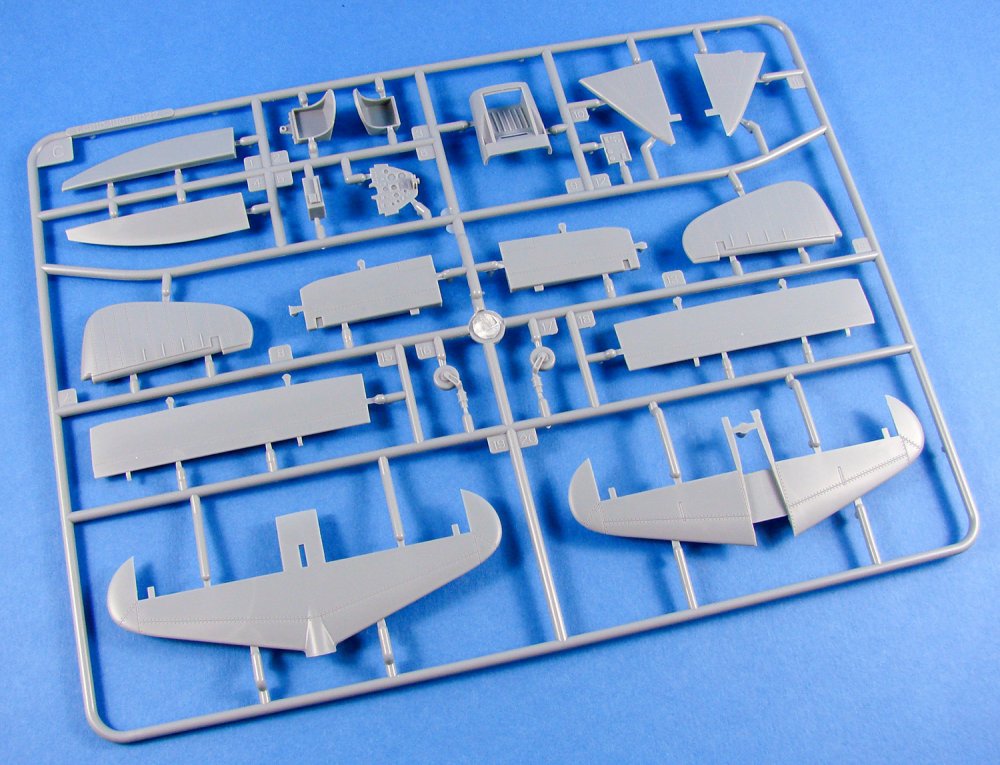
As well as the rather plain cockpit seats, we have the instrument panel with details which I think could be made to look really good when complete, such as the nicely recessed instruments with no gauge detail. There is an instrument panel decal for this, but I suggest ditching that in favour of aftermarket. I highly recommend Airscale instrument and placard decals for this sort of work.
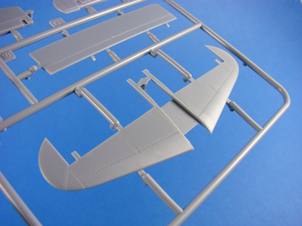
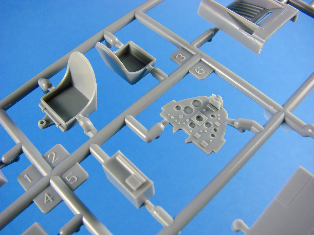
The stabiliser is provided as a full-span upper and lower panel into which the rear fuselage will nicely recess. Elevators are also separate and fitted via tabs, although it will be easy to modify these to be fitted dynamically. A two-part rudder is included, with panel line and rivet detail, but I’m pretty sure these were fabric covered on at least the Mk.1. I stand to be corrected.
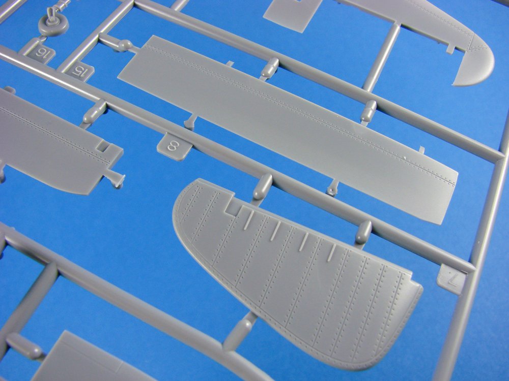
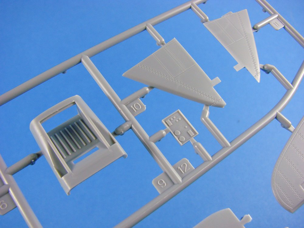
Other parts on here include the port and starboard landing flaps (with no interior detail, but that appears to be correct), nose intake and integral channel, vertical fin and tail wheel/strut, moulded as halves.
Sprue D
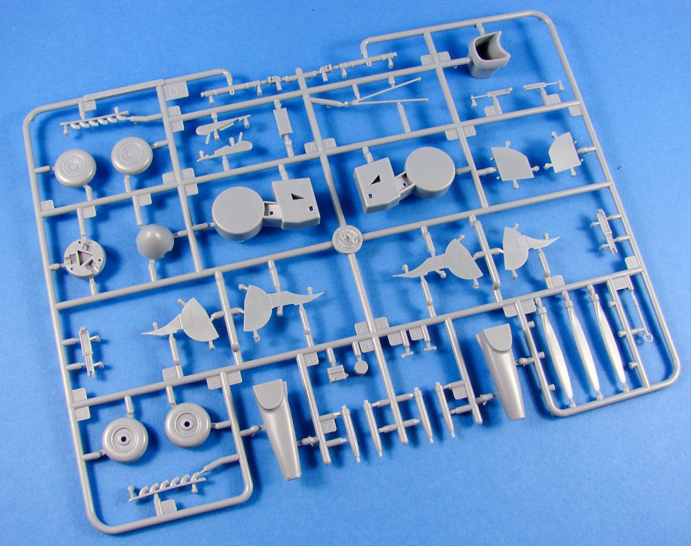
I’m quite surprised that Trumpeter chose to mould their wheel bays in this fashion. They have moulded the wheel recesses as drum shaped sections that don’t extend too much beyond their openings. These areas had straight-edged walls that formed a box which had two corners clipped, so I’m struggling to see why Trumpeter did this. Gear bay doors look good, but again, the details seem very, very simplified with missing elements. The wheels don’t look particularly weighted in appearance. Outer hubs are, to be honest, a comedy parody of the real four-spoked appearance. The undercarriage legs look good, with sharp detail, but again are very simplified in comparison with the real thing.
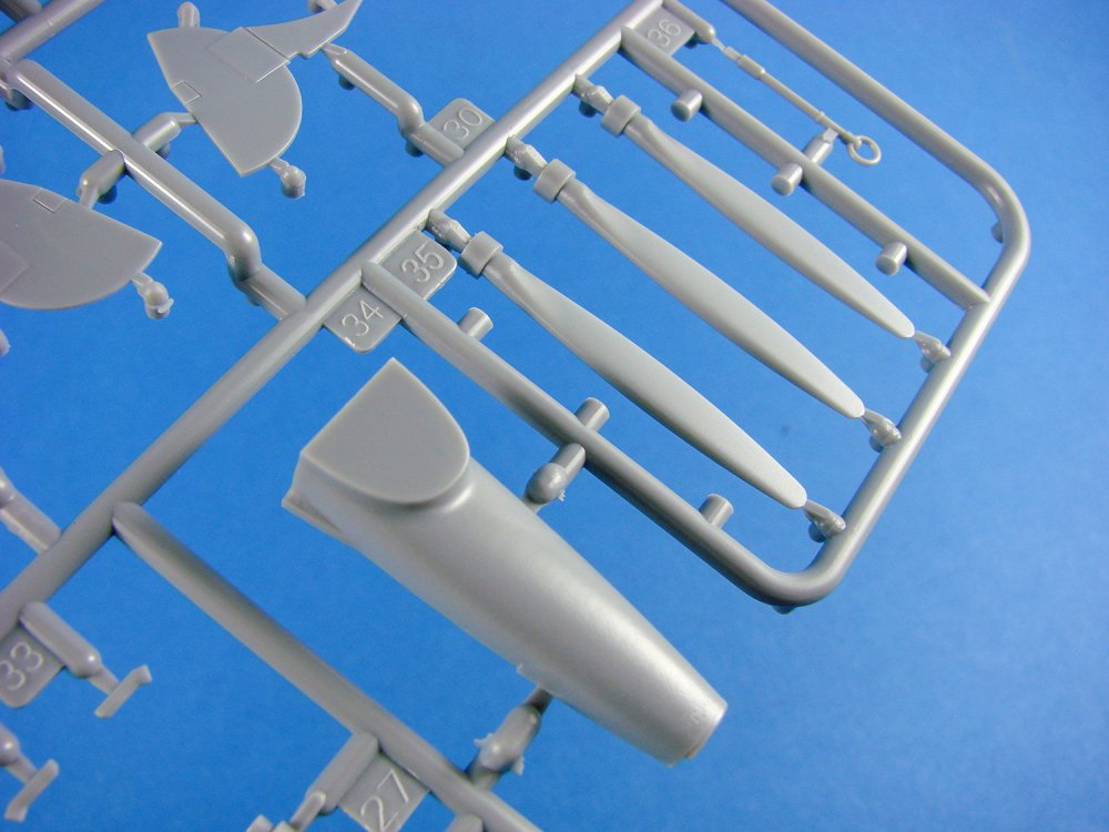
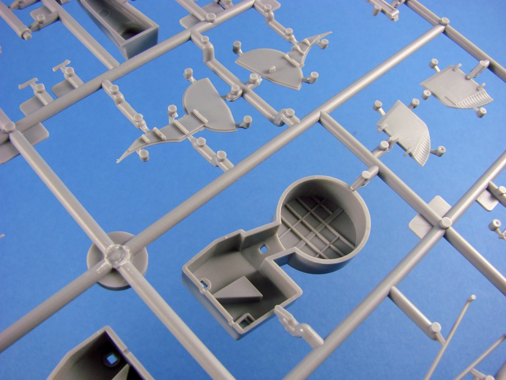

Side cheek intake channels are moulded here, separate to the actual engine cowl, and you’ll also notice the two-part spinner with separate prop blades. Exhaust stubs aren’t hollow, and the shapes look all wrong and lack the droop effect of each stub.
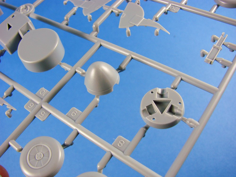
Sprue E
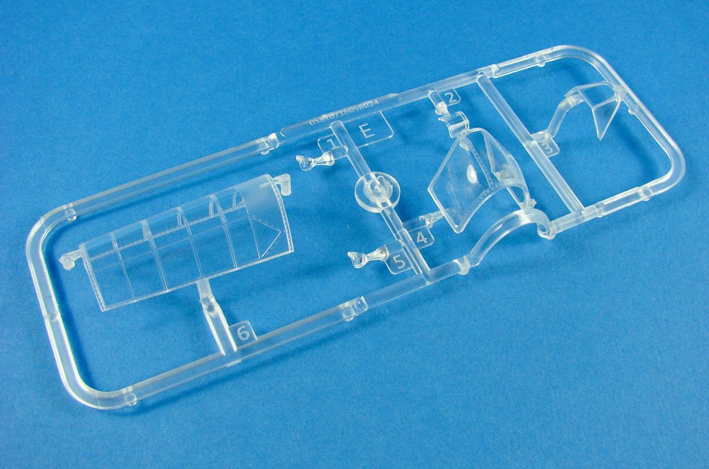
Two things I like about Trumpeter clear parts is that they are almost always bright in appearance and perfectly transparent. Ok, a third…the framing lines are also nicely defined. I really can’t criticise anything here. A major point here is that the canopies aren’t designed to be posed in the open position, but if that cockpit isn’t your main raison d'être for this model, then a closed hood could be a good compromise.
Sprue F (x2)

These sprues concern the external payload of the Firefly and include parts to build two bombs along with their pylons, and also a set of eight rockets that are pre-moulded to their respective pylons. The patter has separate fin parts, although a little clunky in appearance.
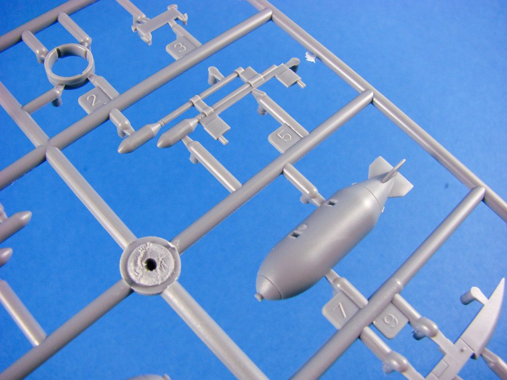
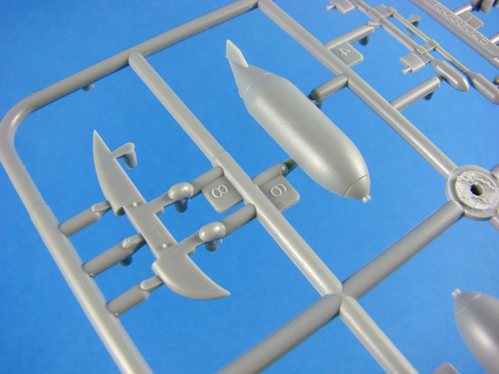

Photo Etch

A single PE fret is included, with just three parts. These are for the intake and radiator areas and the aerial mast. Quality is good, with small tags holding everything in place.
Decals
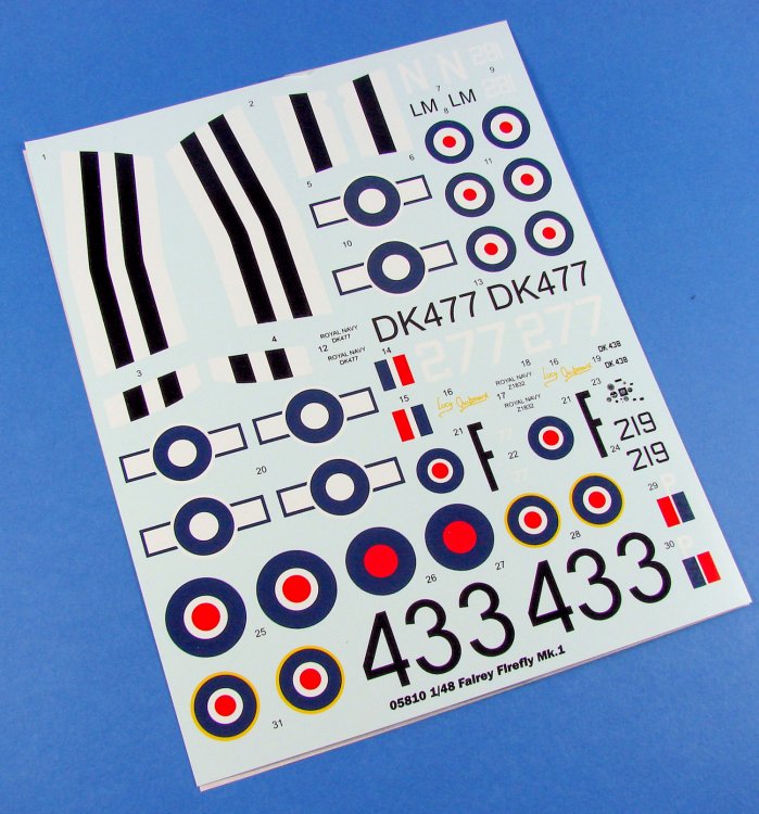
I think these are a locally printed solution as there isn’t anything with any printer name to see. A large, single sheet contains the markings for four machines, including the black and white stripes for the wings and fuselage on one machine. No stencils are supplied. Printing is glossy, thin and with minimal carrier film. Registration also seems good to my eye.
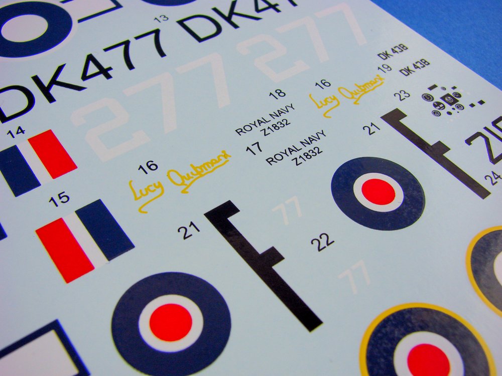
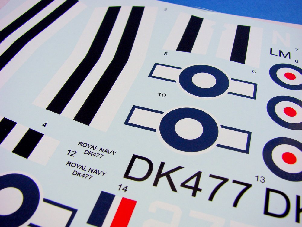
The four schemes offered in this release are:
- Firefly FR.1, FAA 766 Sqn. DK477, RNAS Lossiemouth, 1949
- Firefly Mk.1, 827 NAS FAA
- Firefly Mk.1, July 1943
- Firefly Mk.1, DK438, 1771 Sqn. HMS Implacable, 1945
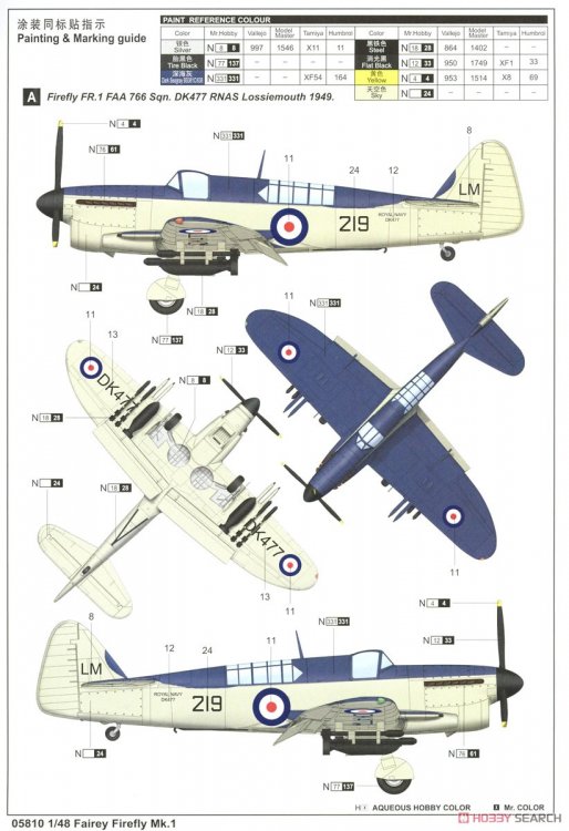
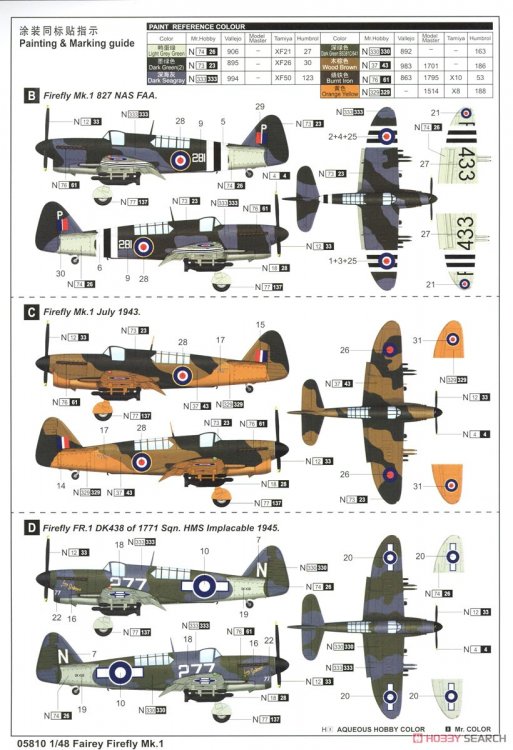
Instruction Manual
The manual shows the construction of the Firefly over 14 simple, unambiguous stages, with clear line drawing illustrations. Colour reference is supplied in Gunze colour codes, and PE placement is obvious. A parts map is also included.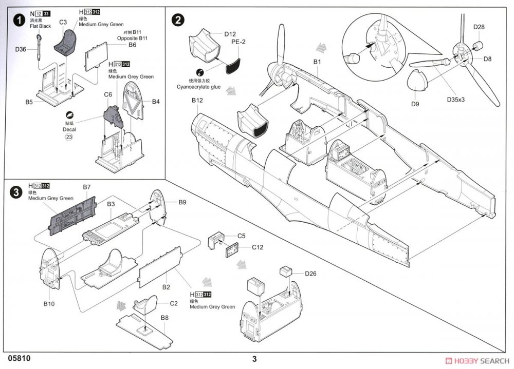
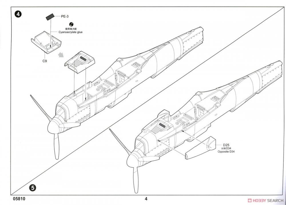
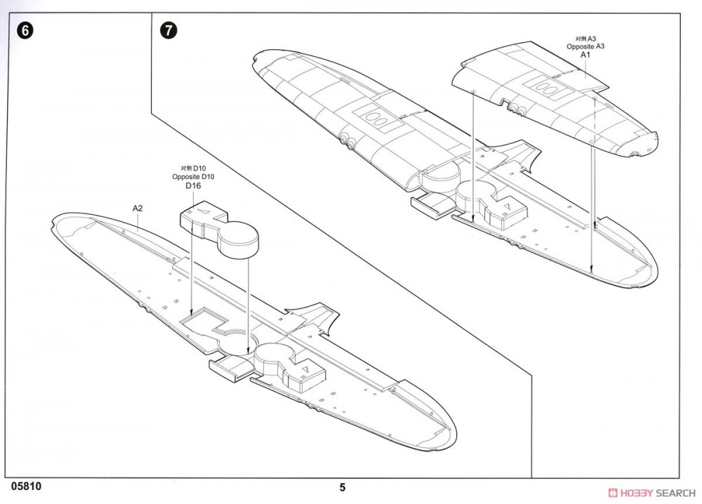
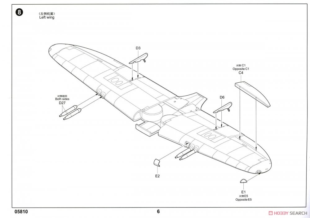
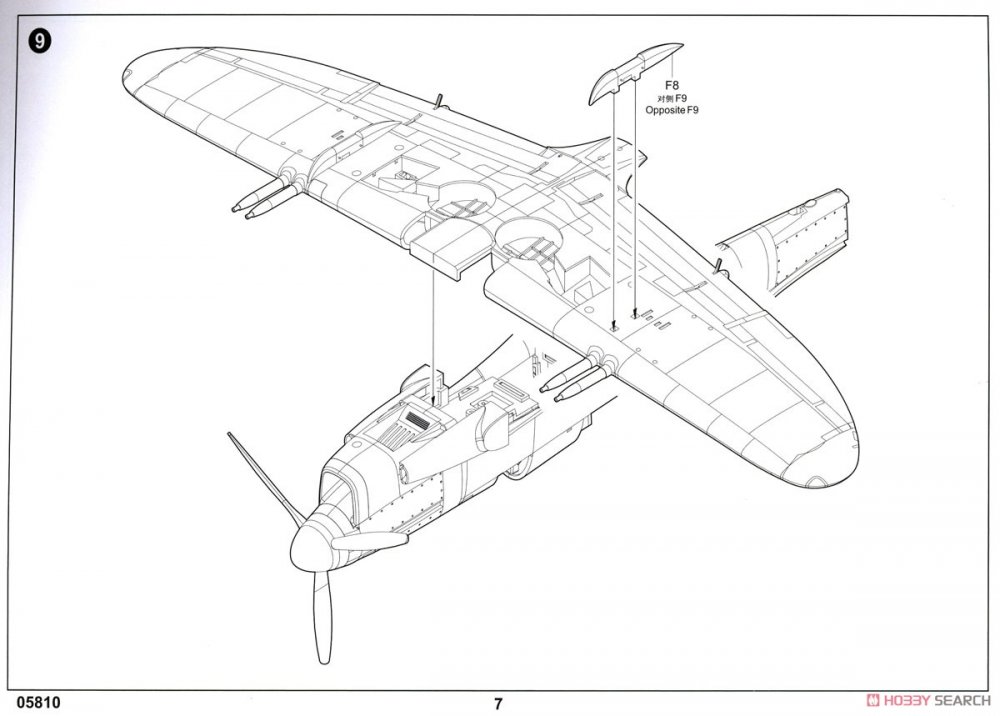
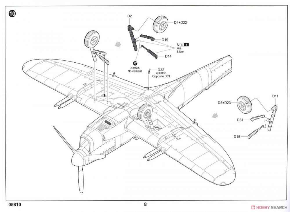
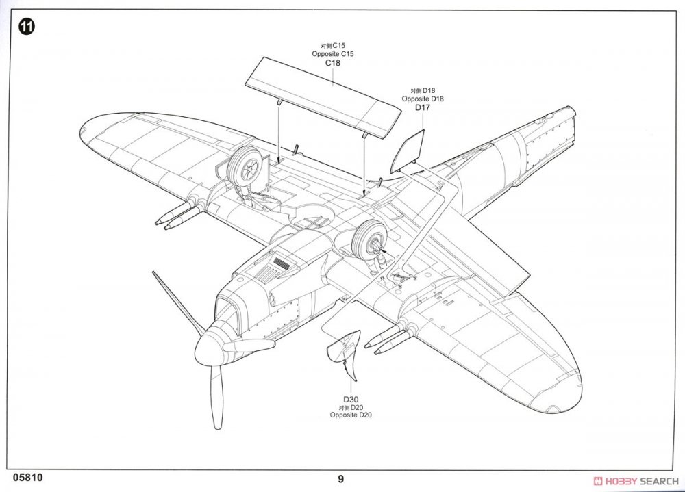
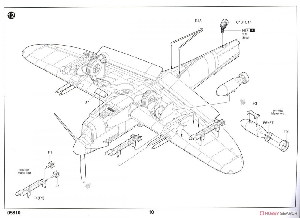
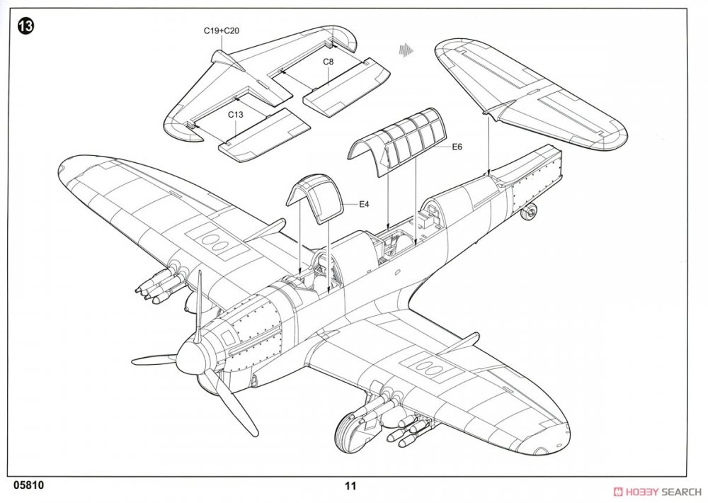
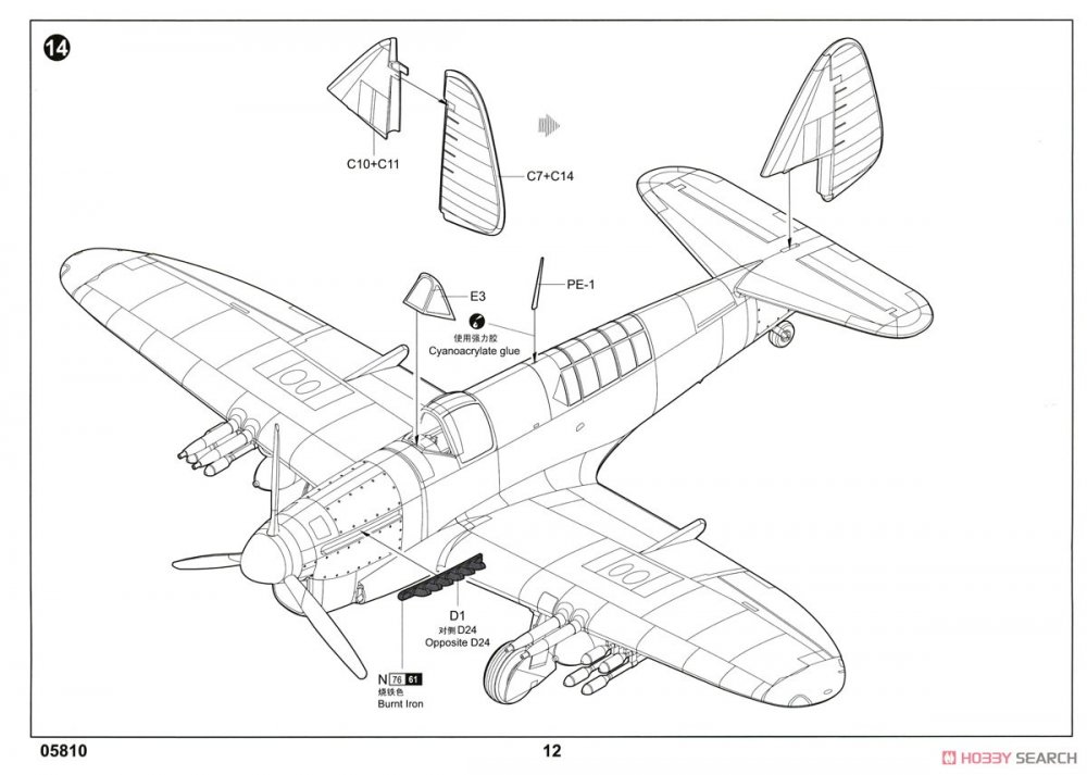
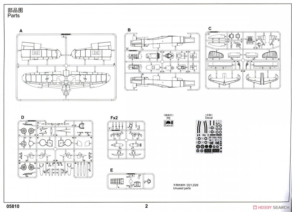
A colour sheet is included, highlighting the four schemes, with good scheme depiction and paint call-outs, plus decal placement. Other paint codes are supplied for Vallejo, Model Master, Tamiya and Humbrol.
Conclusion
This is pretty much a mixed bag, especially for a new-tool kit. Whilst I quite like the exterior (to which I would add extra riveting), the interior is somewhat lacking, and many details are also too simplified. I don’t know if Trumpeter actually ever saw a Firefly before tooling this kit, or even bothered to Google a few images. Such a shame really, but I’m sure the aftermarket boys will be able to fix the wheels and interior, and maybe even the wheel wells, and help us to create something that’s actually rather nice. It’s a nice base from which to work if you want to put the extra effort in without seeking out the AZ Models release. For me, I’d quite like the resin of the AZ kit and to graft it in here. I usually like to be able to point out issues in a review and then to come up with solutions, but for many things here, I’m afraid that I’m at a loss.
My sincere thanks to Pocketbond for sending this kit out for review here on LSM. To buy this kit, check out your favourite local or online retailer.

-
2
-
1/35 EAST EUROPEAN HOME STUFF
MiniArt
Catalogue # 35584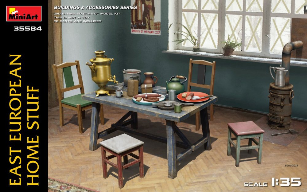
Every good Eastern European home needs good Eastern European home stuff, right? Without a doubt. As long as it’s not Morphy Richards, Kenwood, Sony, Ikea or anything else that was manufactured outside of the 1940s, then this set should be just about perfect for your diorama. MiniArt creates some wonderful and quite leftfield sets for an unspeakable number of diorama possibilities, and this time we have some nice, antiquated-looking items that could well have adorned the interior of an Eastern European home, or maybe even some of the more rural areas of 20s, 30s and 40s Germany or France.
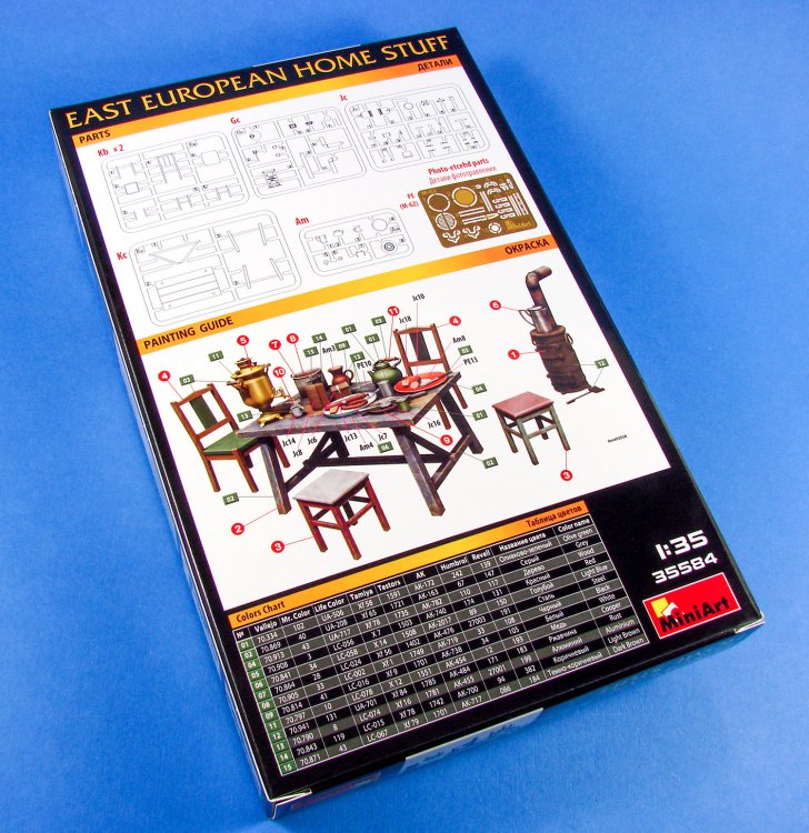
This set comes in a box which is way too large for the parts included, but it pretty much standard for many of MiniArt’s figure and diorama releases. The box itself has a colour rendering of such a period house with a Russian propaganda poster on the wall and a parquet floor. All the items you see in that room (with the exception of the plants and poster) are supplied in this new release.
Opening the box reveals a small, clear sleeve that contains five small light grey sprues and a single small white sprue. Also in that sleeve is a carboard wallet that holds a single PE fret. Each sprue is designed to hold one particular element of this set, meaning that you can build a table from a specific table sprue. Simple logistics, but it makes things easier!
Sprue Gc – Stove
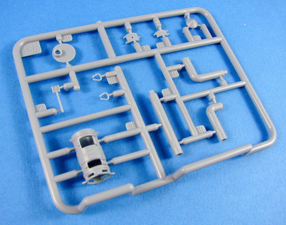
This is one of those typical wood-burning stoves that I most associate with log cabins out in the wilderness, but of course is typical of this period in Eastern Europe. The main stove is superbly moulded as a single, hollow part with provision for two shutter doors for fuel and cooking etc. to be added. Slide-moulding has been used for this part. There is a name plate on this with Russian writing, but this can be erased if you want to use it for a non-Russian diorama. The sprue also contains shutter doors, piping to remove the smoke to outside of the house, pipe flange and hotplate, and handles for the top of the stove. Two PE parts are supplied for the wood burning plate and the cooker element of the stove.
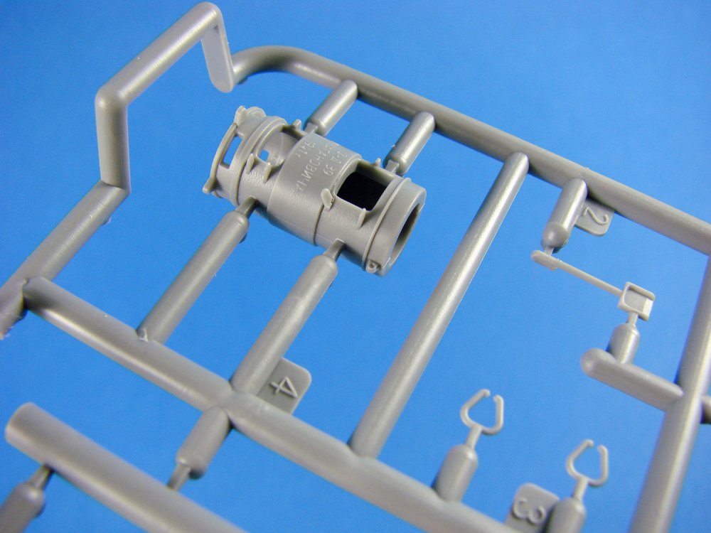
Sprue Kb – Stools and Chairs (x2)
There are two chairs and two small stools that are to be made from these sprues, which are both identical. These comprise of two A-frames each, two cross members and a seat lid. Also found here is a chair with a back, with the rear legs and back forming the main part, and the seat and forward legs being the last two parts. The seats and stool are very simple in appearance with no fancy carving, as would befit the home of a poor agricultural or Eastern European family.
Sprue Kc – Table
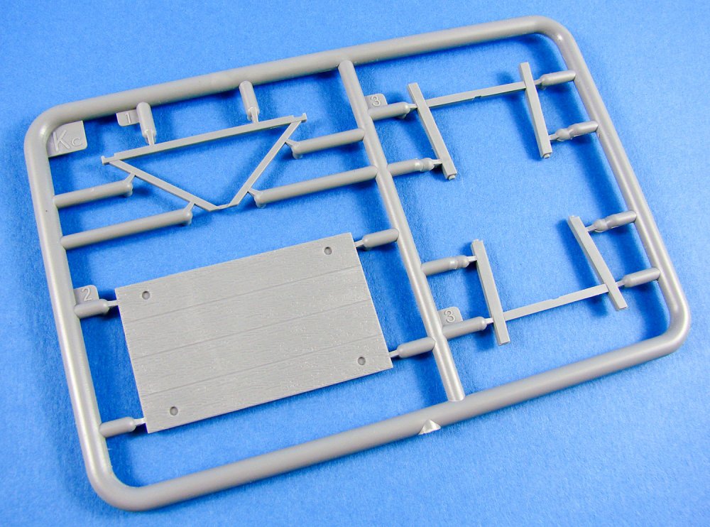
A simple sprue containing only four parts that make up the main table. These are the table top with its wooden plank effect, two sets of H frame legs and a centre spreader that connects these together and secures to the top. I quite like the wood grain effect of this which should look good with some paintwork that is weathered back down to the wood. All parts have positive locating pins for assembly.
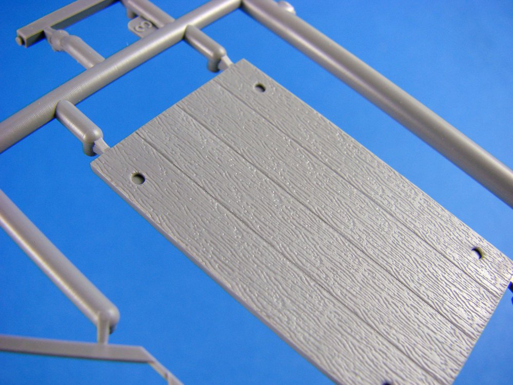
Sprue Jc – Water Urn and utensils
The urn has quite a simple beauty to it despite its utilitarian appearance. Both plastic and PE elements go to create this little desktop masterpiece. The main body is built as halves and onto this fits the lid, along with a PE and plastic ring. A fancy four splayed leg is fastened to the underside. As well as these are ornate handles and a tab with a separate valve. Thirteen parts go to build up this little masterpiece, but some are very small, so take care! You’ll also fund cups and utensils on this sprue.
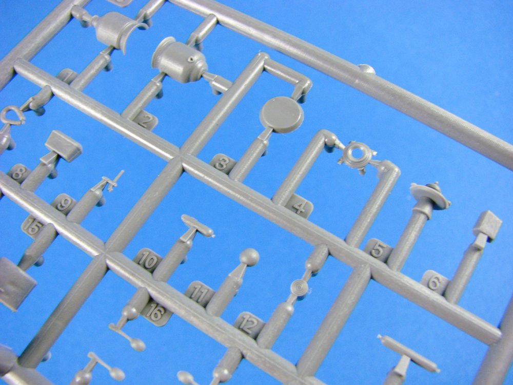
Sprue Am – Utensils

Set apart due to its white styrene, this small sprue contains the various parts you’ll need to construct the different pans, teapot, milk jug, and also the plate. A number of these items will also require the PE fret for the more delicate details. More slide moulding is used here to as to create hollow vessels.

PE fret

A stated, this is where you’ll find those small but important parts for the utensils etc. This small fret is protected in a card envelope. Quality is excellent, and the removal tags are thankfully small.
Instructions
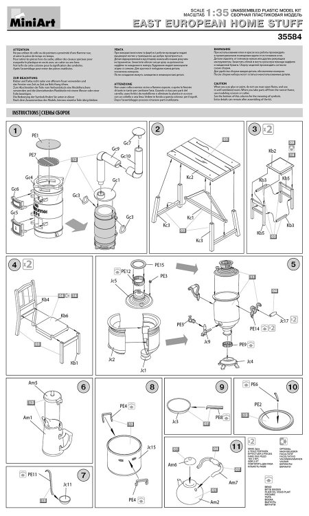
As well as the painting guide on the back of the box, showing you the completed items in suggested colours, the single sheet of instructions shows assembly in simple line drawing format and is easy to follow.
Conclusion
What a great little set! Simple, yet effective and with endless possibilities for the diorama modeller. This kit is also pitched at a relatively inexpensive price so it’s well worth considering for your next project. Just be careful with those tiny parts!Highly recommended
My sincere thanks to MiniArtfor this review sample.
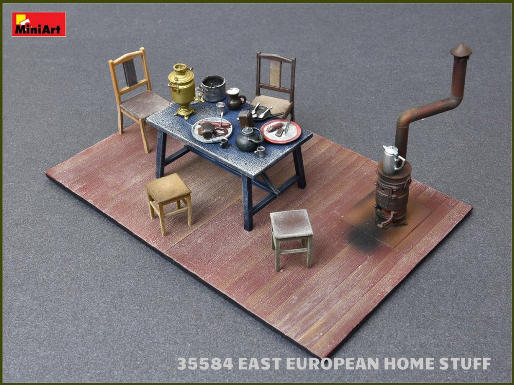

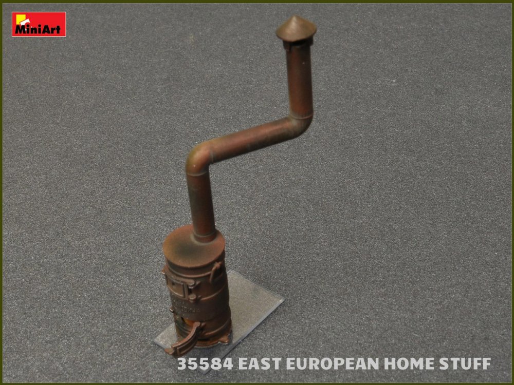
-
2
-
-
When did he say this? A few weeks ago in Japan we were talking about the stressed skin.
It has been a while since Neil upgraded his computers to cope with this level of computation.
-
Super review! Well worth the effort. Like the comparisons too.
ICM has a winner here.
-
1:35 “China Clipper” U.S. Medium Tank M4 Composite Sherman
Asuka Model
Catalogue # 35-034
The M4 Sherman, officially Medium Tank, M4, was the most widely used medium tank by the United States and Western Allies in World War II. The M4 Sherman proved to be reliable, relatively cheap to produce, and available in great numbers. Thousands were distributed through the Lend-Lease program to the British Commonwealth and Soviet Union. The tank was named by the British for the American Civil War general William Tecumseh Sherman. The M4 Sherman evolved from the M3 Medium Tank which had its main armament in a side sponson mount. The M4 retained much of the previous mechanical design but put the main 75 mm gun in a fully traversing turret. One feature, a one-axis gyrostabilizer, was not precise enough to allow firing when moving but did help keep the reticule on target, so that when the tank did stop to fire, the gun would be aimed in roughly the right direction. The designers stressed mechanical reliability, ease of production and maintenance, durability, standardization of parts and ammunition in a limited number of variants, and moderate size and weight. These factors, combined with the Sherman's then-superior armour and armament, outclassed German light and medium tanks fielded in 1939–42. The M4 went on to be produced in large numbers. It spearheaded many offensives by the Western Allies after 1942.
https://www.youtube.com/watch?v=CcVR61Xg8SM
The relative ease of production allowed large numbers of the M4 to be manufactured, and significant investment in tank recovery and repair units allowed disabled vehicles to be repaired and returned to service quickly. These factors combined to give the Allies numerical superiority in most battles, and many infantry divisions were provided with M4s and tank destroyers. After World War II, the Sherman, particularly the many improved and upgraded versions, continued to see combat service in many conflicts around the world, including the UN forces in the Korean War, with Israel in the Arab–Israeli Wars, briefly with South Vietnam in the Vietnam War, and on both sides of the Indo-Pakistani War of 1965. Paraguay retired three Shermans from the Regimiento Escolta Presidencial (REP, Presidential Escort Regiment) in 2018, which marked the end of service of the final Sherman tanks in use anywhere in the world.
Extract courtesy of Wikipedia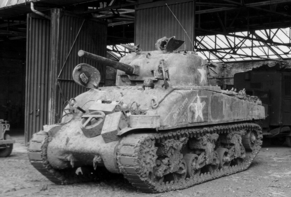
China ClipperThe kit
Asuka Model (formerly Tasca) are probably the undisputed kings when it comes to the M4 Sherman. In fact, this particular 2016 kit has almost SIXTY re-pops to date, from six different companies. There’s little doubt that the kit, in its many incarnations is quite a gem, and this particular release is that of a Sherman Composite with a welded rear hull. China Clipper served with the 68th Tank Battalion, 6th Armoured Division and this specific machine has been recreated down to the stowage that is seen to adorn it in some photos of her. Asuka Model has provided this as a set of resin pieces that I’ll look at later. I can’t comment on kit accuracy, but many dozens of reviews of the sprues in various releases tend to lean towards this being possibly the best range of Sherman kits on the market. This release is packaged into a surprisingly shallow but very full box of styrene, with an overhead view of China Clipper on the lid, providing a great reference for the aforementioned stowage parts that are included. Lifting the tight lid reviews 19 sprues of dark green styrene which are generally packed into separate, stapled clear sleeves, except for where multiples of the same exist, and these are packed together.
Two clear sprues are also provided as are four lengths of vinyl track, set of flexible polycaps, a piece of black rubber material, one fret of PE, a single decal sheet, bag of Value Gear Detailsresin parts and two sets of instructions. One thing that is obvious from this release is that Asuka Model/Tasca possibly had no idea about how many different variants of the Sherman would be released, as some sprues, whilst different, have the same nomenclature. It’s quite normal to see every letter of the alphabet used on different sprues over different releases, with no real conflict between the various kits (with exceptions to the rule). The instructions do explain about the inclusion of two Sprue J in the box, and to check that you indeed do use the correct parts from each. I think the overlap here is very small and those parts with the same number are actually entirely different, so you shouldn’t encounter any issues.

I’m fairly new to armour and was surprised in the first instance to see vinyl tracks in this release as I’m led to believe that these are the things which most incense armour modellers. I do admit to seeing them recently in a 1/16 Takom kit but thought that it was more common for separate track links, the likes that we are now seeing in Rye Field Models and Takom 1/35 releases. Nonetheless, the moulding of these is excellent with sharp details. Each side is split into two pieces (for some reason) and they appear to assemble easily with CA. Instructions suggest priming them with Tamiya primer. Be careful what you do use in case it attacks this more fragile material.
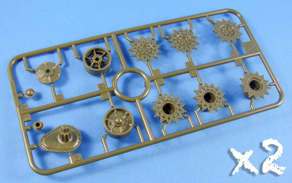


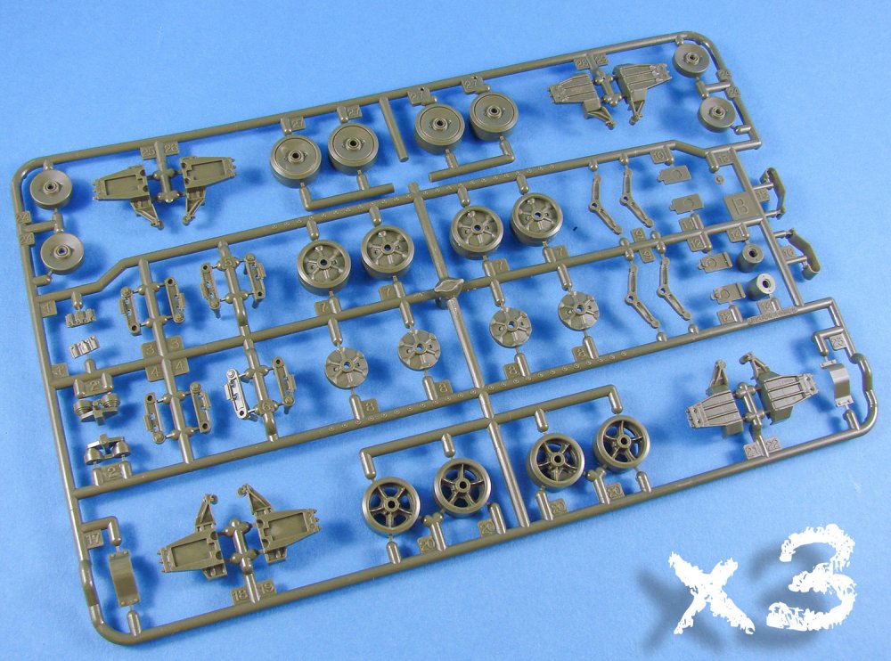


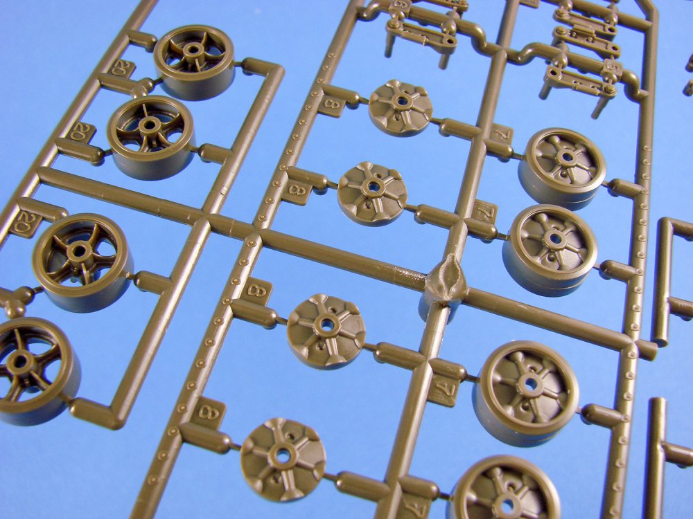
Five of the sprues are given over the drive and idler wheels, roadwheels and the three bogie units on each side of the hull. You will need to mix and match the polycaps with these during construction as these will grip the wheels to the bogies when fitted. As the tracks need to be made to sag slightly, I’m pretty sure the polycaps aren’t there so the wheels can rotate. Being able to rotate them before fitting the tracks will make painting easier though. To set the suspension height of the individual bogies, some rubber material is provided which you can use to custom load-out the individual units and set the height of these. This is all full explained in the manual,
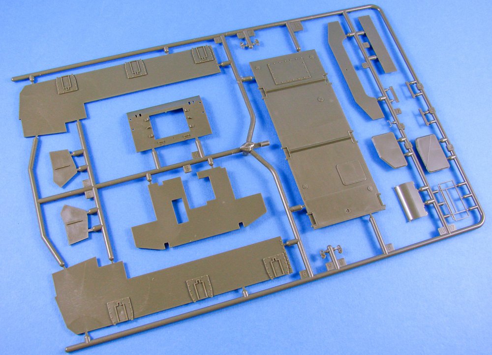
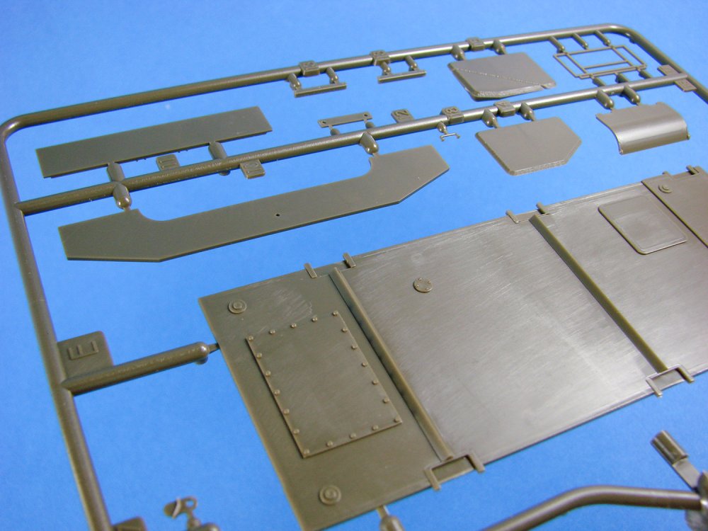
You will notice that the typical bathtub style lower hull isn’t present in this kit. This section is built up from a number of plates and an internal former. Two slightly different forward differential covers are supplied in this kit, on Sprue J, and you will need to identify the one you need from construction Stage 7.
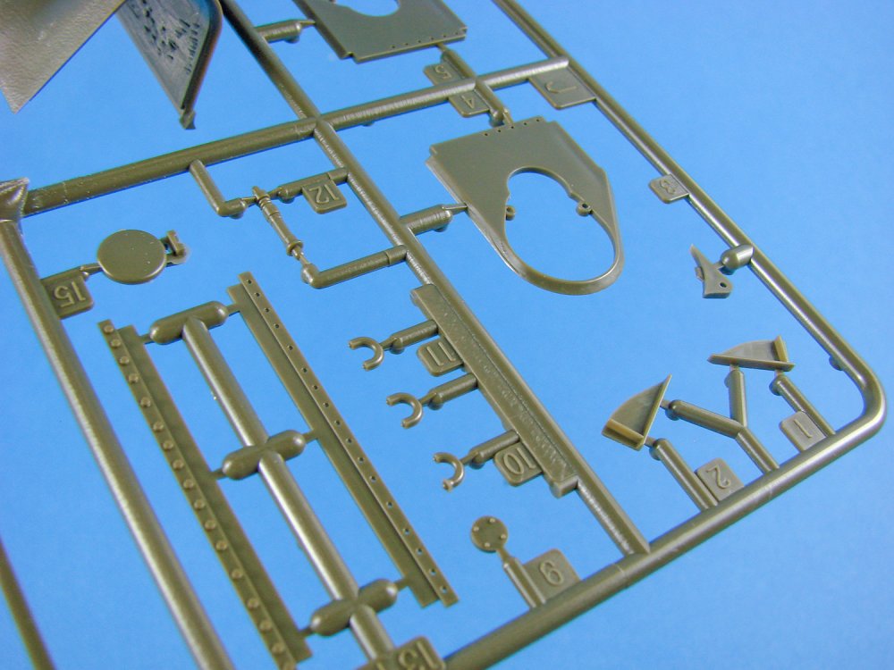
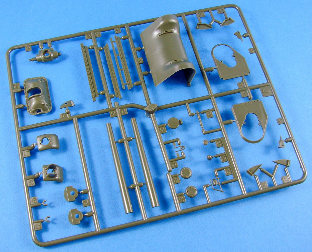
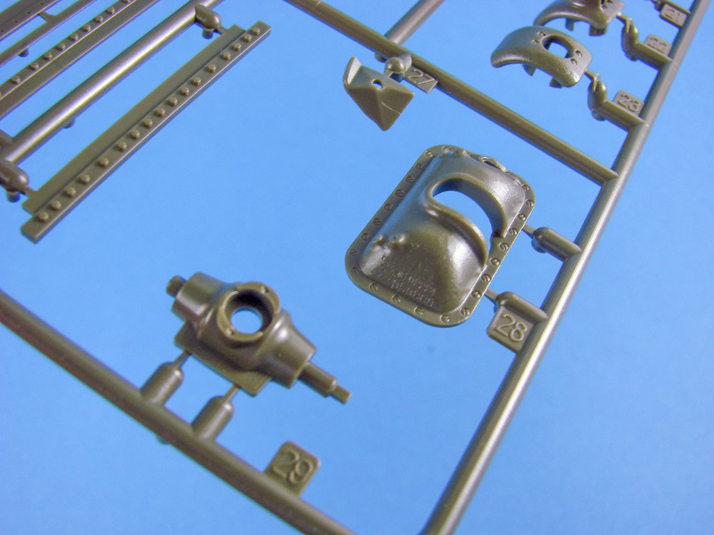
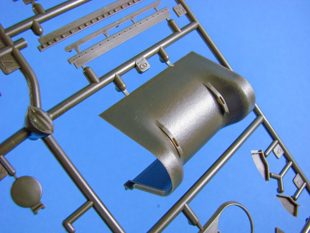


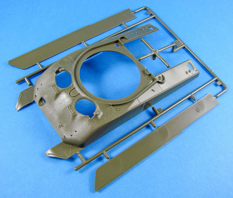


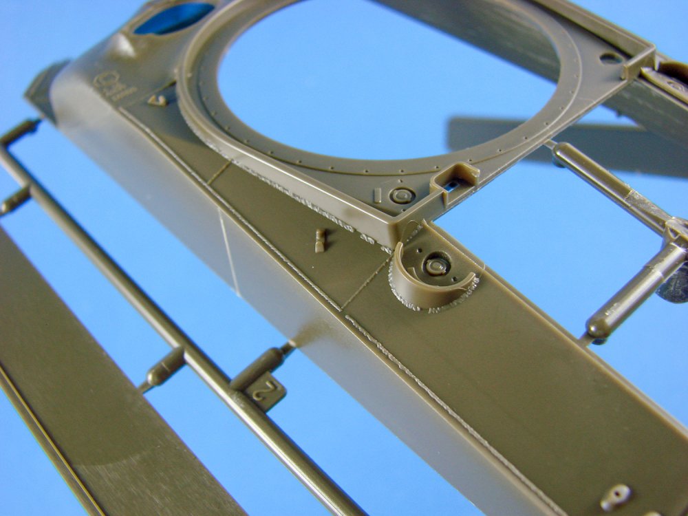
I absolutely love the depiction of the upper hull with its rough forward casting which looks entirely organic and non-contrived. Of course, the rear hull is welded plate, as are the forward mudguard section. Weld seam detail is also very fine. I’m no aficionado as to which angle of arc this is supposed to be, that seems to be so important to some factions of this hobby, but as someone who can weld themselves, I think the depiction looks excellent. The rear engine deck is a separate entity, and the two forward crew hatches are also separate parts and can be posed open, despite there being no interior to the kit.

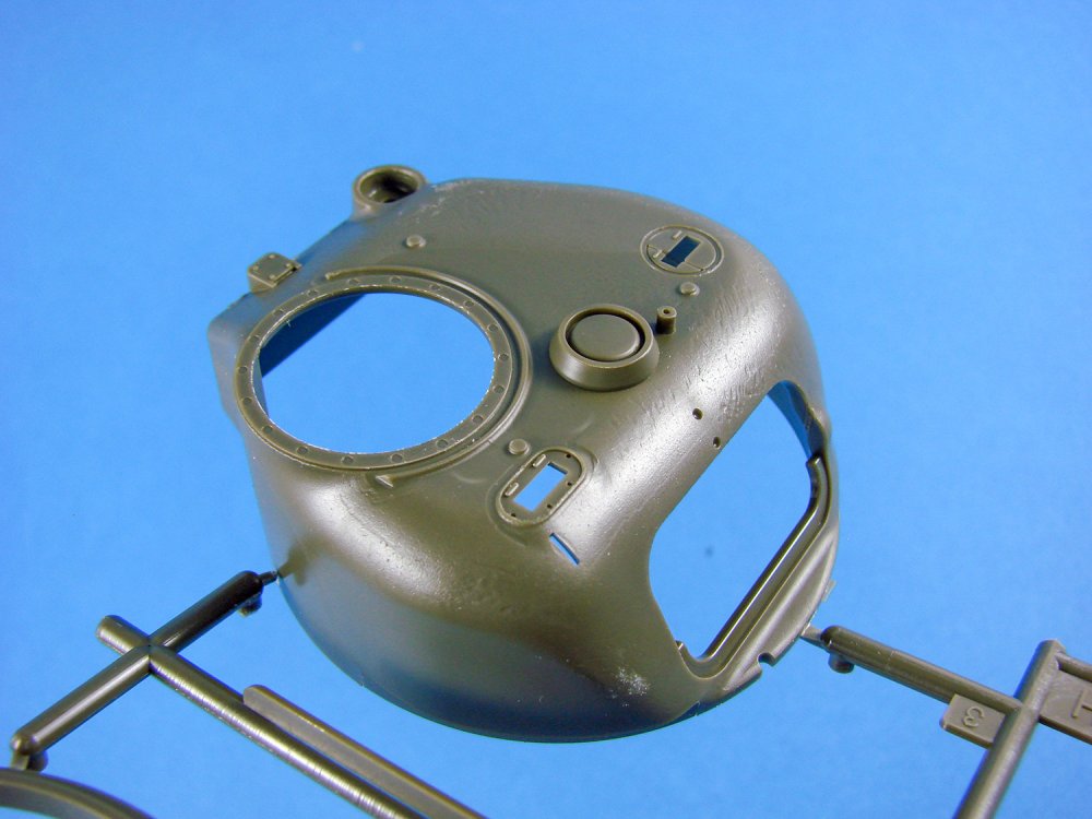
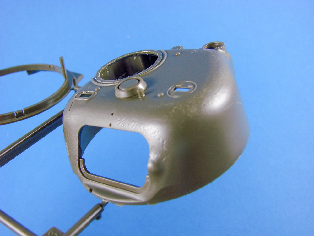
Realistic textures also stretch to the cast effect of the turret, although they aren’t as pronounced here. I don’t know whether that’s through design or omission. No internal details are supplied here, and the lower ring is a separate part on the same sprue. The gun and mantlet of course designed to be able to elevate and the barrel is a two-part affair that you may consider replacing with a metal, rifled alternative. Inside the turret, there is no gun detail, as befitting a model with no interior included.
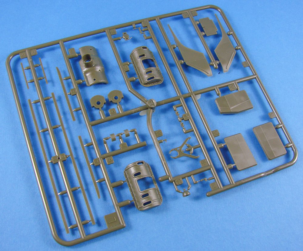

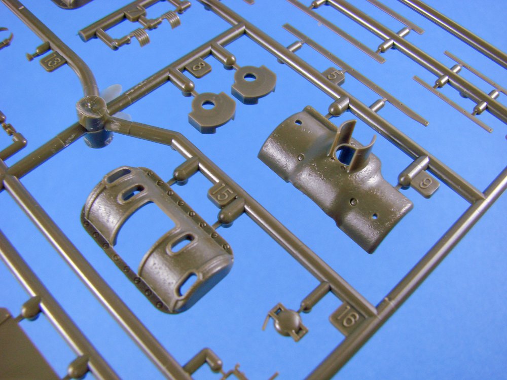
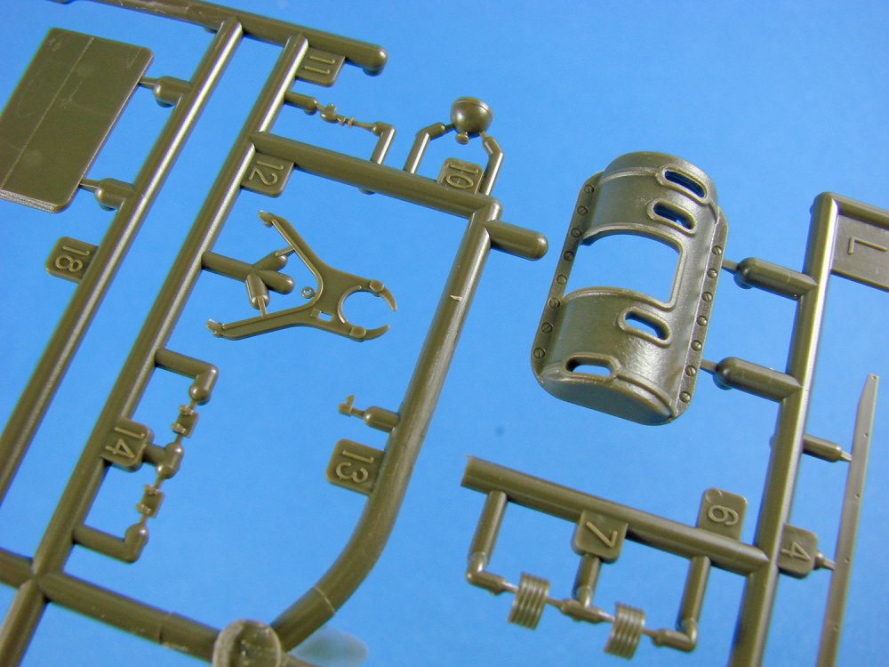
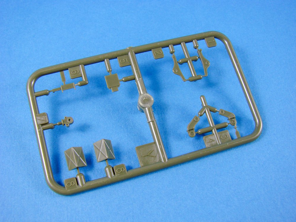
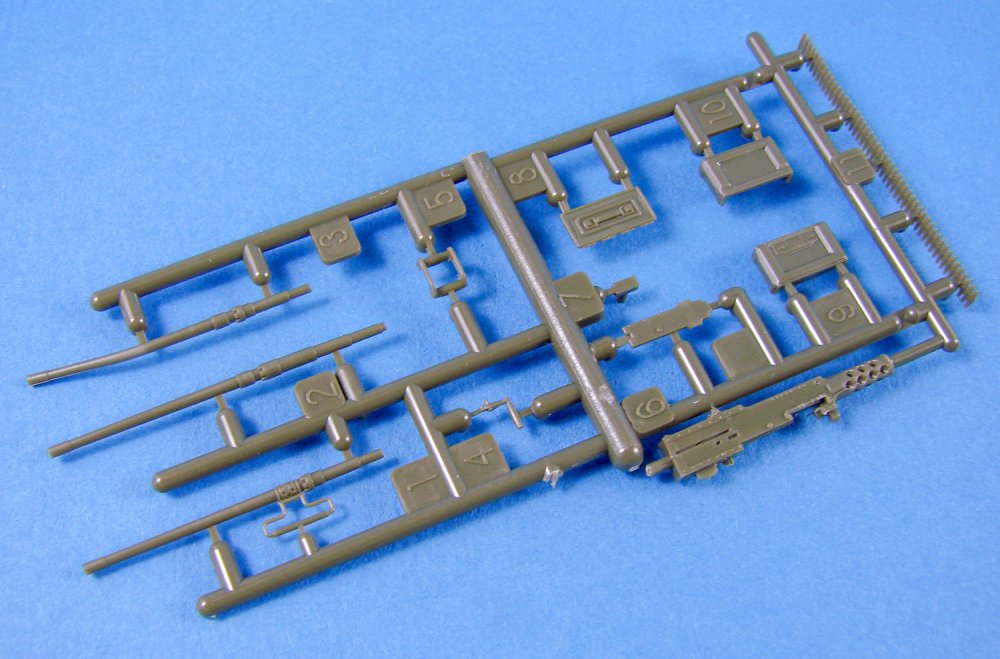
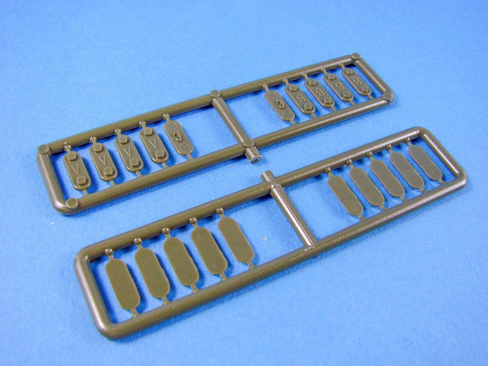
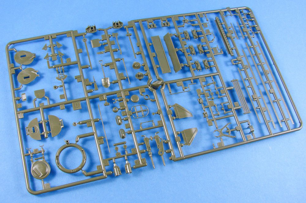


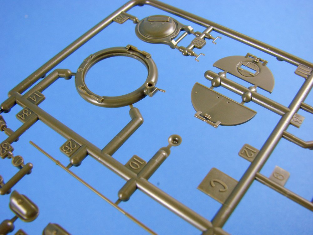

MG detail for the mantlet is excellent, as is the cupola-mounted gun, but you may also choose to replace this with a brass version for more authenticity. I note that a section of rigid styrene ammunition is included for the MGs. To be able to use this, you’ll probably need to dip this in just-boiled water for a minute or so to be able to properly manipulate it. The commanders/cupola hatch can also be displayed in an open position, but as with the other posable hatches, you’d be best sticking a figure in there to disguise the murky, dark and empty interior.
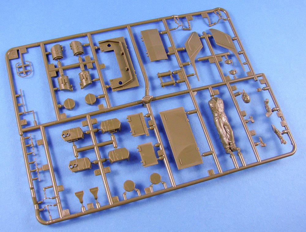
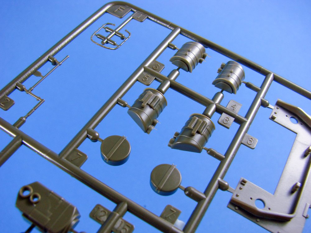
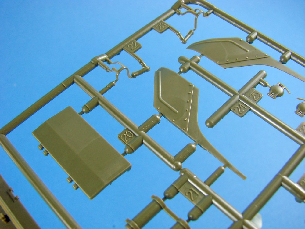
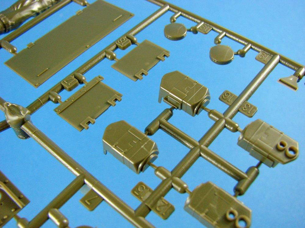


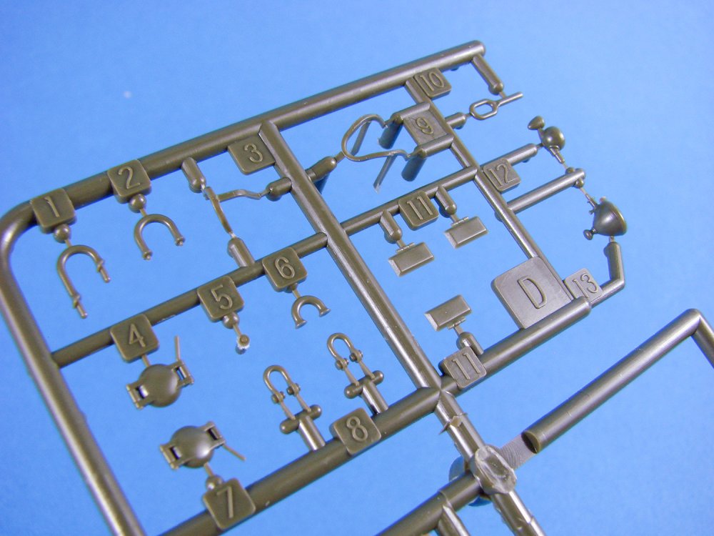
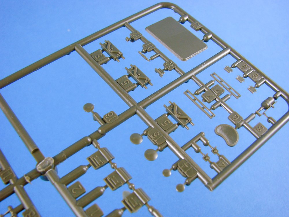
Clear parts are included for the periscope and the clarity is excellent.

A single PE fret is included that contains parts for engine grilles, Grouser boxes, air cleaners, etc. Quality is excellent, and the removal tags are small enough so as not to cause any difficulty in removing and preparing the parts.

As this model focuses on China Clipper, you won’t be too surprised to know that this is the only decal scheme in the box. After all, that’s what you bought this for, right? I imagine that the decals will be printed locally, and they are simple in execution, all being white markings for this one machine. Printing is sharp and thin, with minimal carrier film. Of course, registration is irrelevant here.

I do admit that when it comes to instruction manuals, I would prefer a regular book-format production that sits easy on the workbench, but this is one of those multi-folded, panoramic things that tend to get one confused when you dart between various sequences…very much like the Bandai instructions on some of their kits. Whilst there’s a lot of Japanese on this paper, this is also translated into a very reasonable level of English that is easy to understand. Illustrations are in line drawing format, but the instructions themselves look a little cluttered. Tamiya paint references are supplied throughout the assembly sequences, with a simple extra default options that states using Olive Drab where a paint reference isn’t supplied.


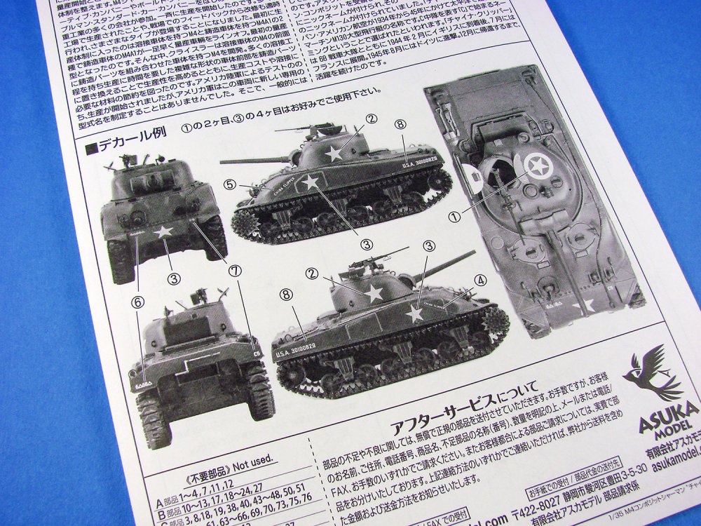
Extras
Of course, this is China Clipper, and the resin extras are also what help to push this kit. These consist of some superbly cast parts, including tent and tarp rolls, deck stowage 75mm crates, packs and helmets, wooden storage boxes and a stowage board. With the exception of the latter that is cast in brown resin, the rest of cast from light grey resin and look superb. Details are sharp and the mastering of these is first rate, and clean-up minimal before use. Adding these to your model will certainly create a visually interesting and authentic-looking miniature of China Clipper. A separate sheet of instructions is included with a full side printed in English.
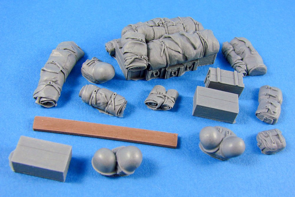
Conclusion
Being an aircraft guy, this is the first time I’ve seen an Asuka Model kit, and it’s been an education in reading through the reviews of the Sherman series on various reputable websites. Apart from the specifics that pertain to this specific release, there’s not really too much more can be said with regards to accuracy except to state that these kits are respected for exactly that. For your money, you get a box that’s crammed with plastic, and with plenty for your spares box, plus the added resin parts to boot. This is a fantastic release of this specific machine and should look superb when finished, even with the vinyl tracks supplied. I look forward to building this as the darker months approach later this year.Highly recommended.
My sincere thanks to Asuka Model for the review sample seen here.

-
1
-
-
That PE is insane. I don't think I saw anything as complex as that before. Serious kudos...
-
9 minutes ago, daz greenwood said:
Great kits aren't they James? And beautiful build too!
Pretty amazing. How's yours coming along?
-
1
-
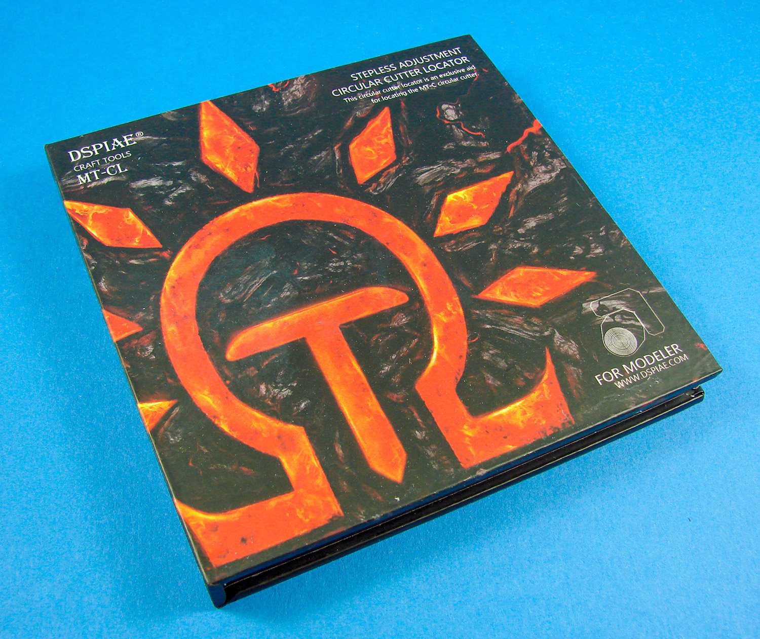
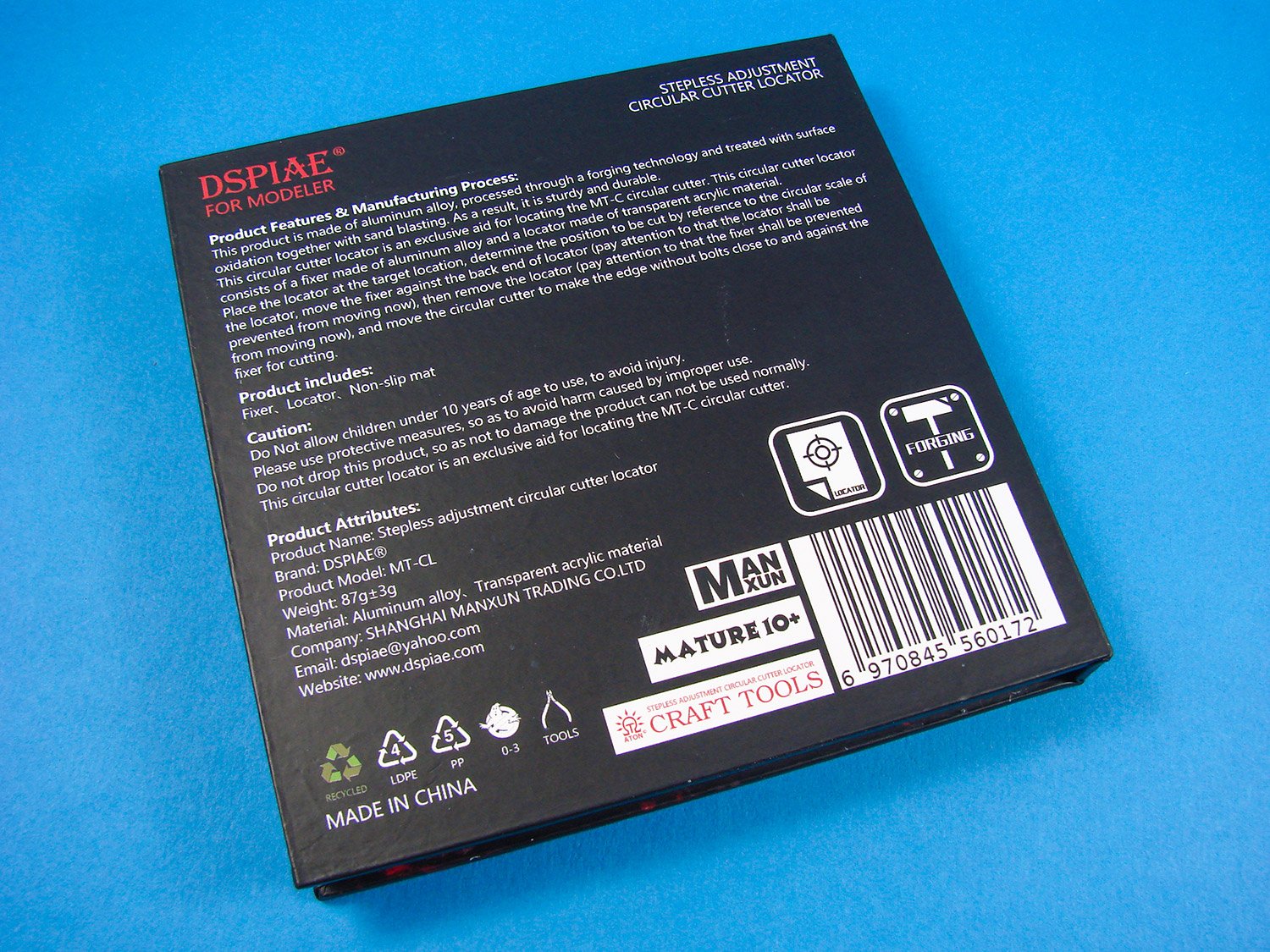


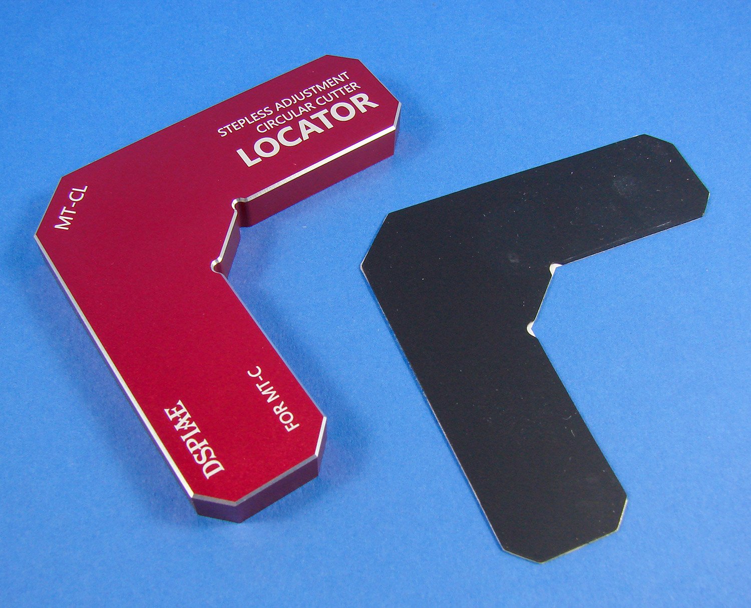
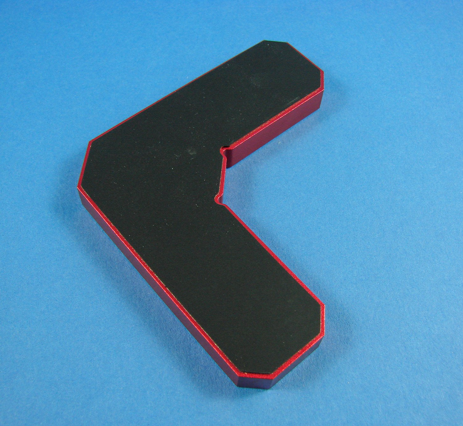
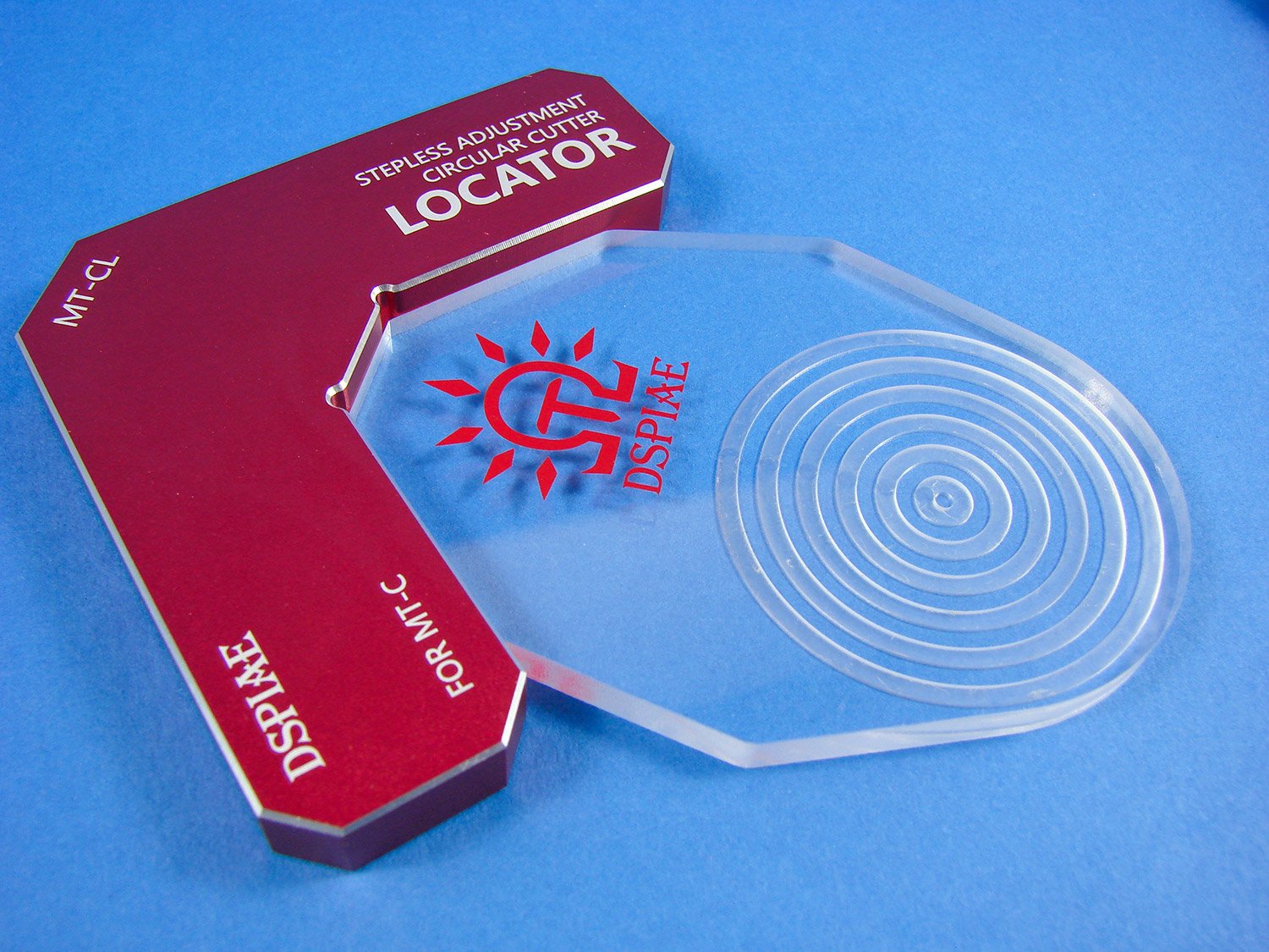

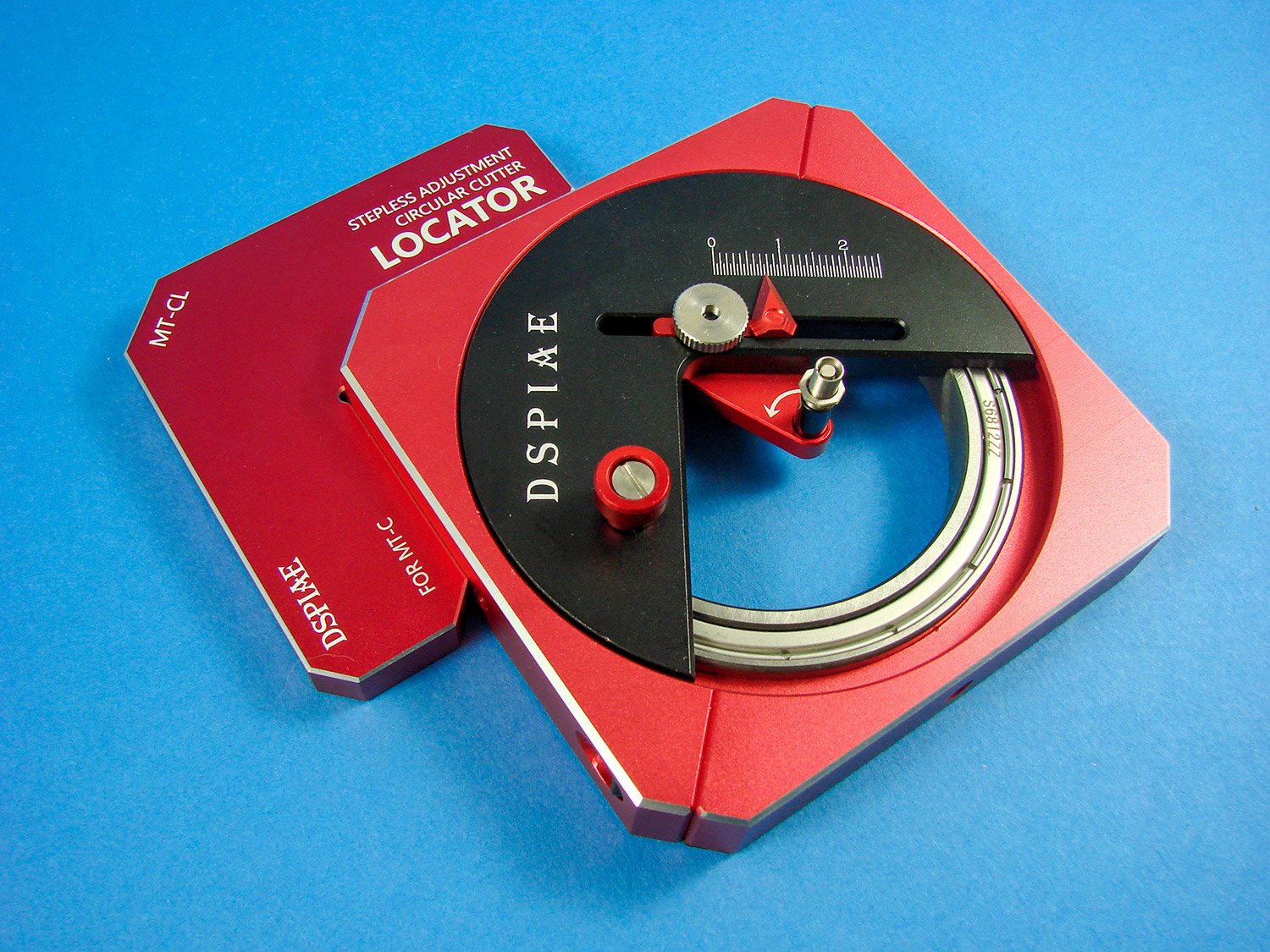
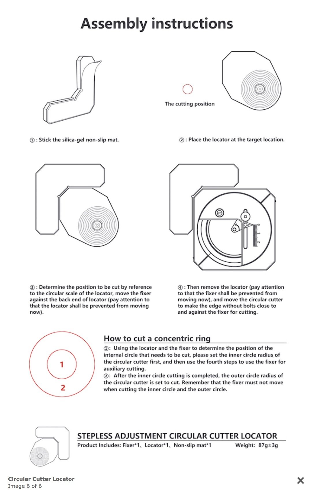
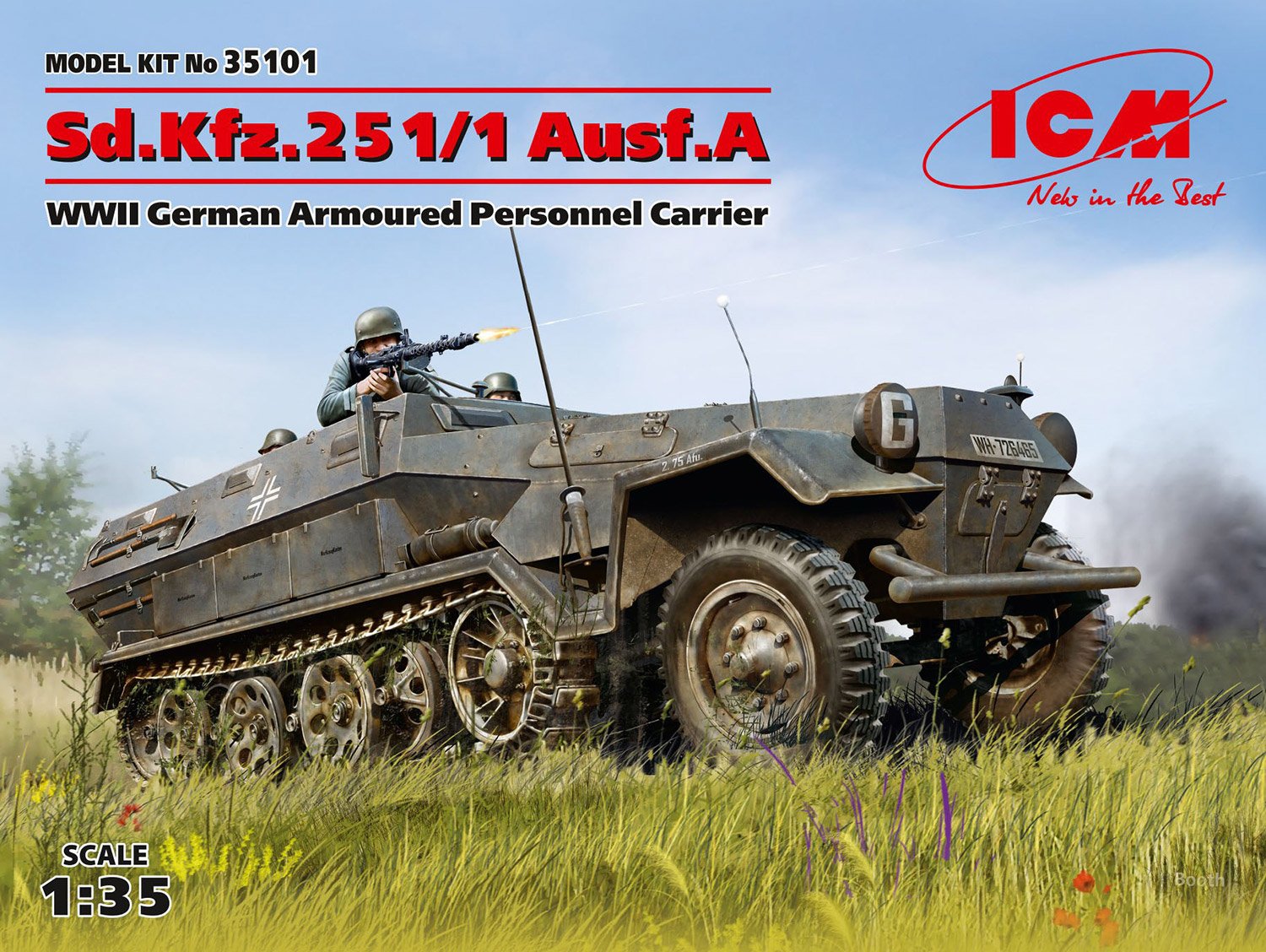

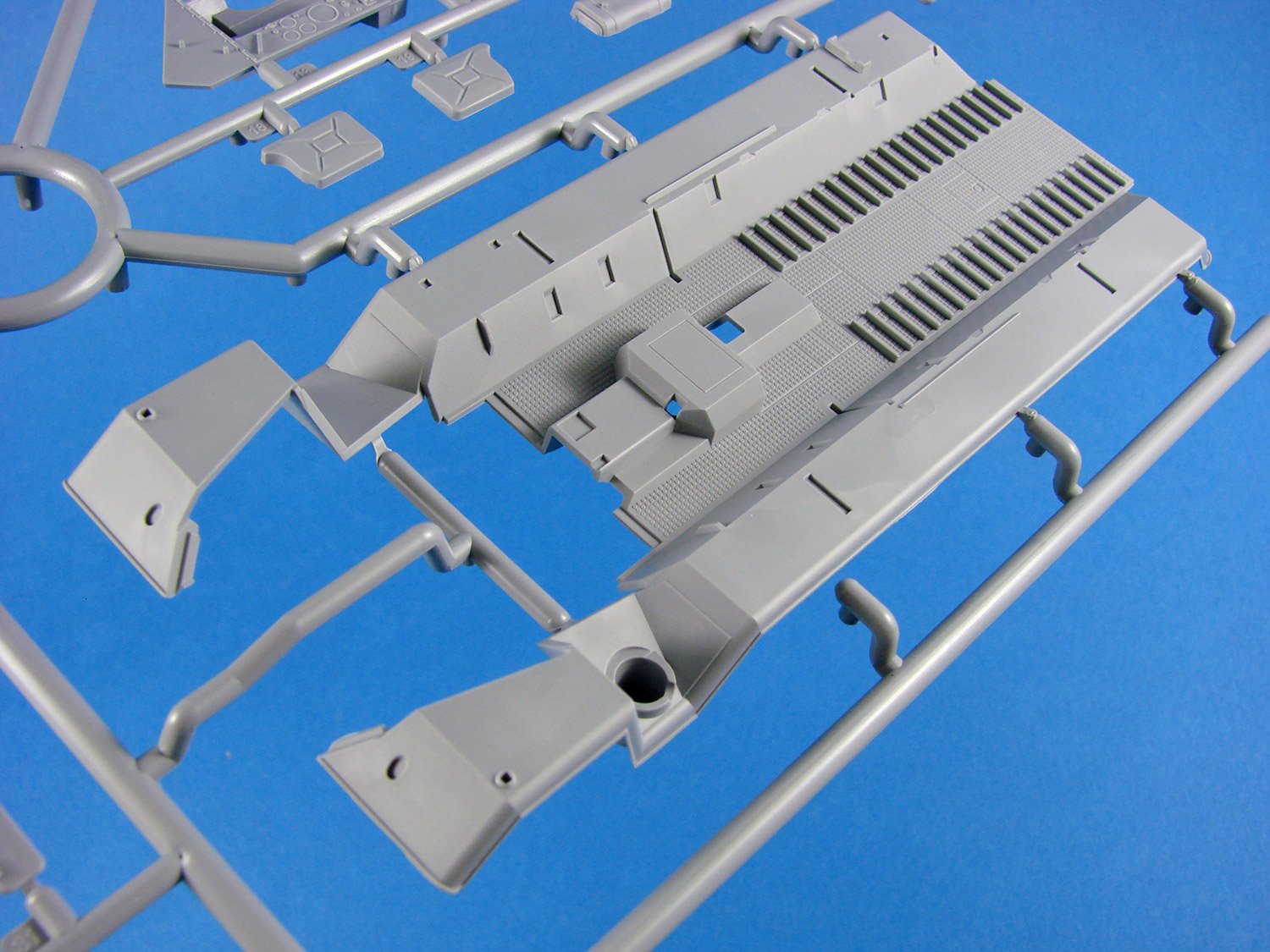
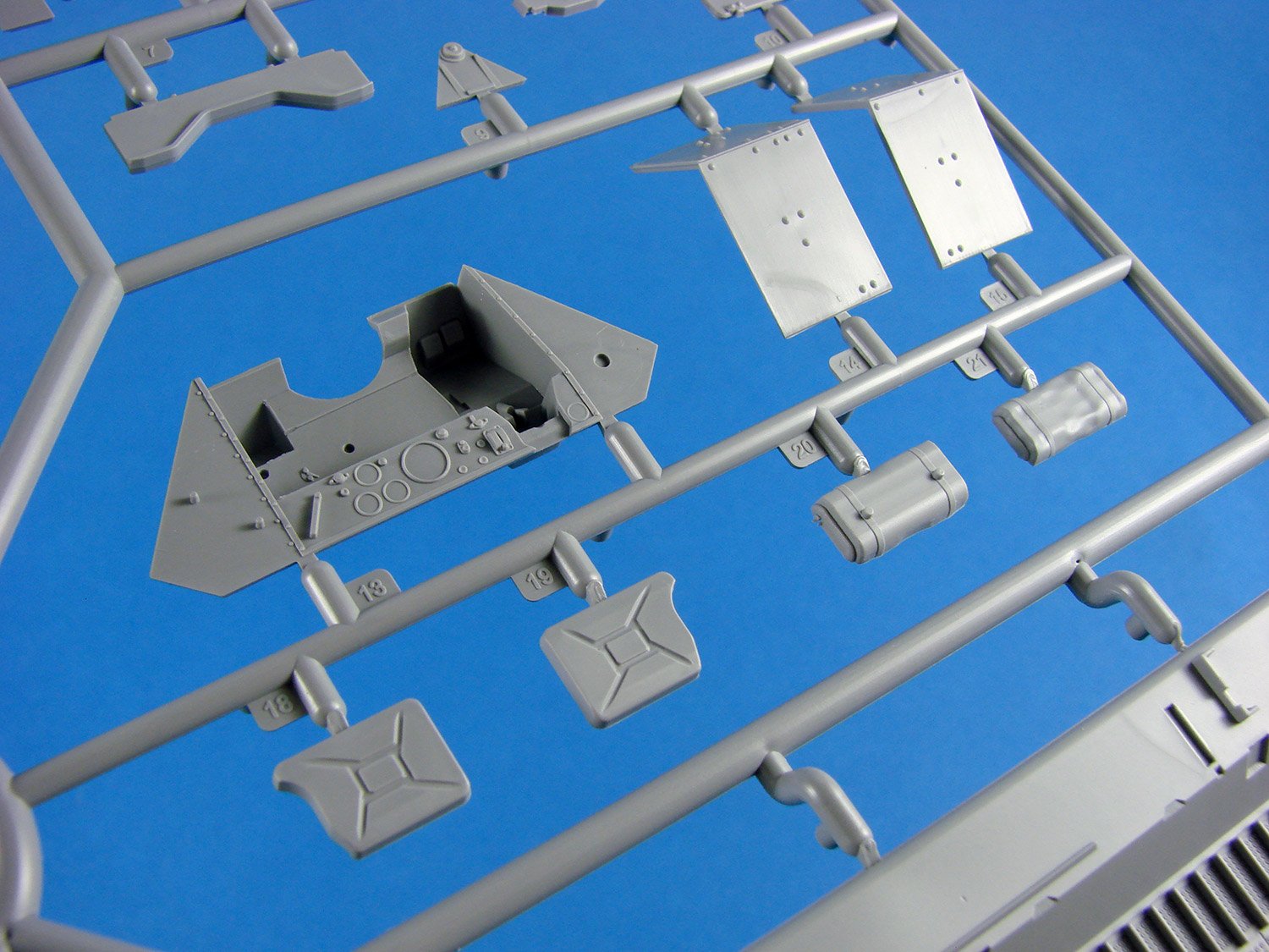


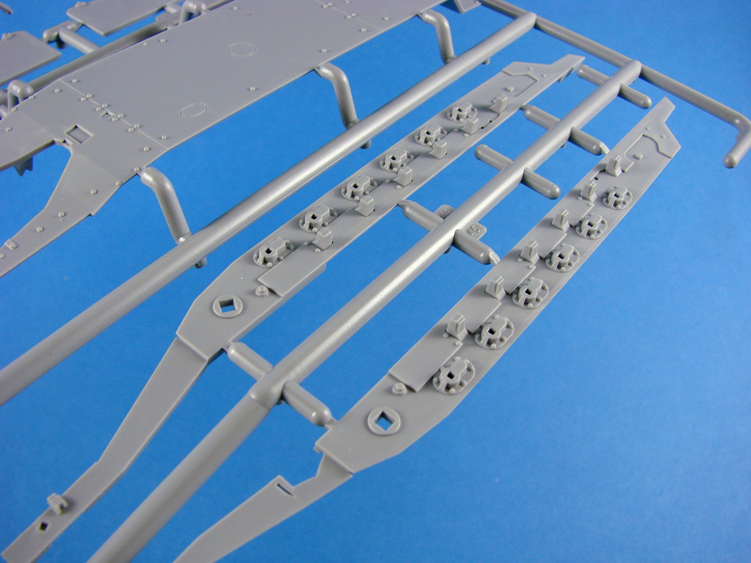
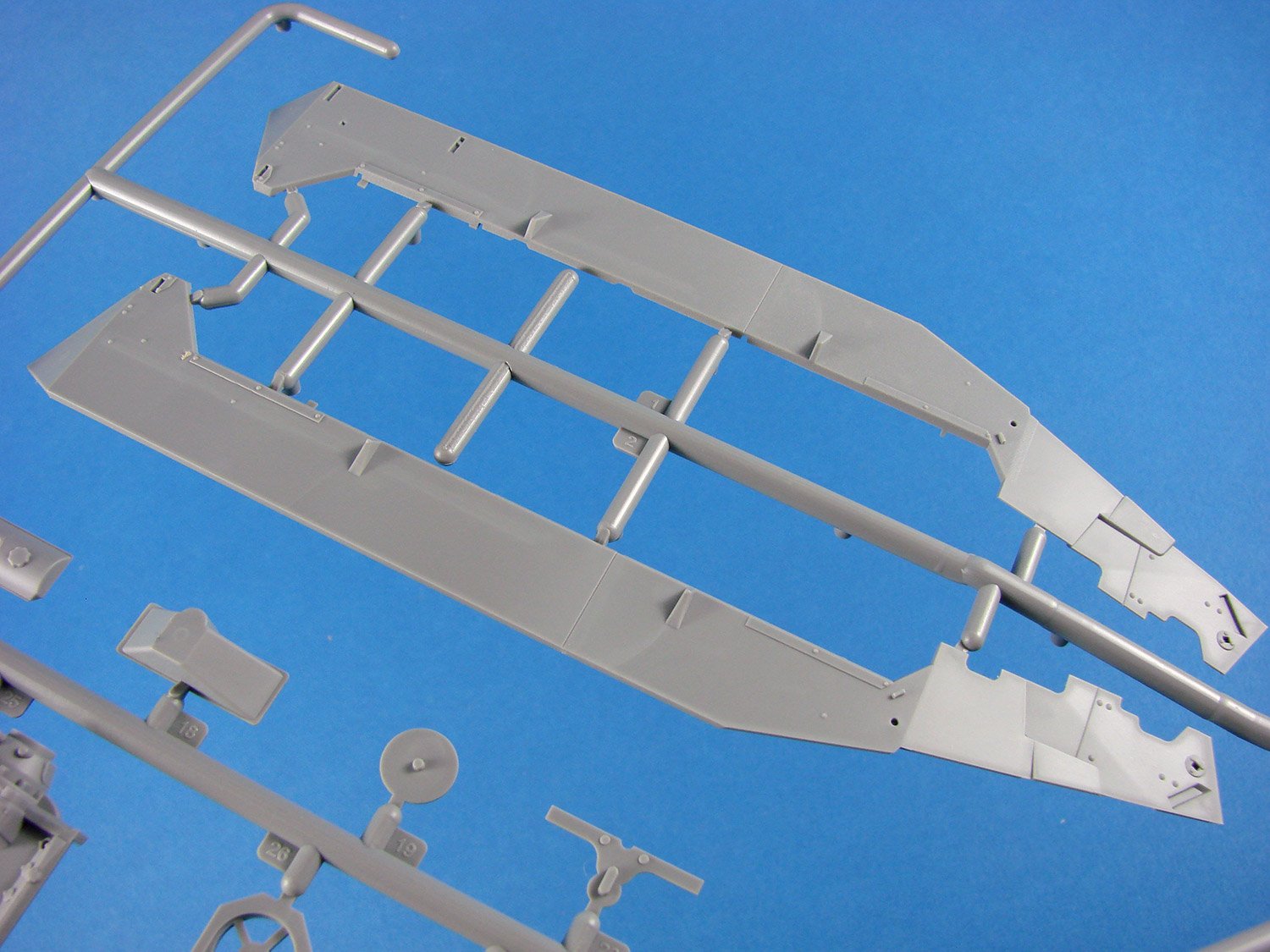
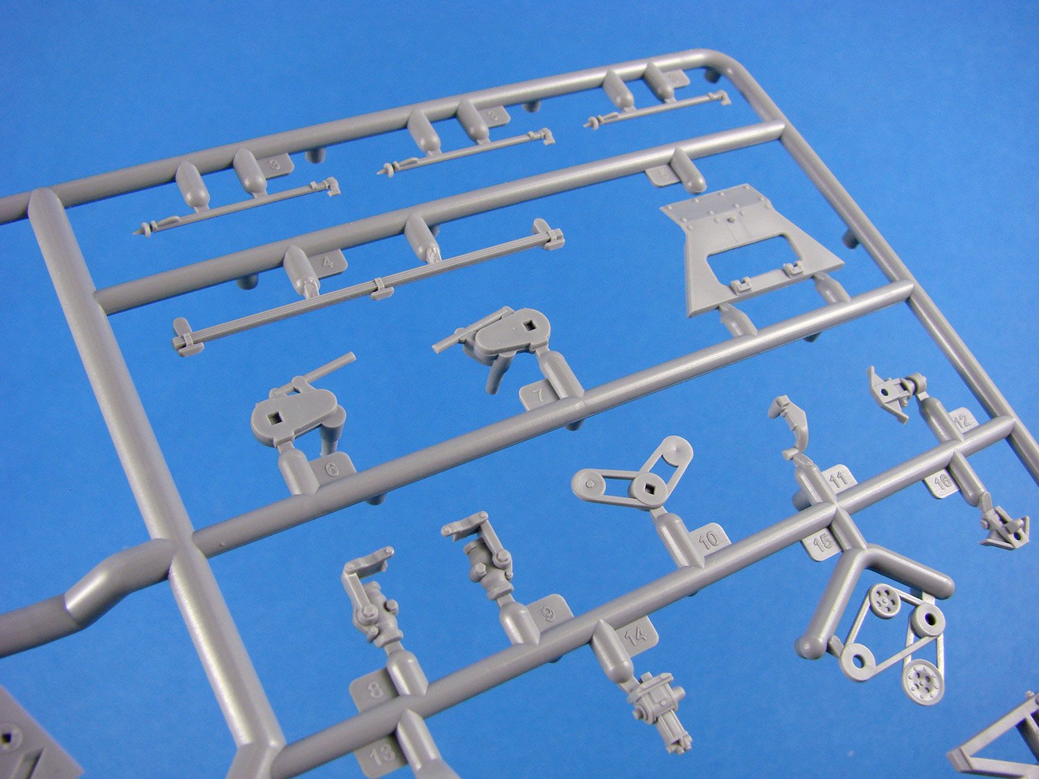
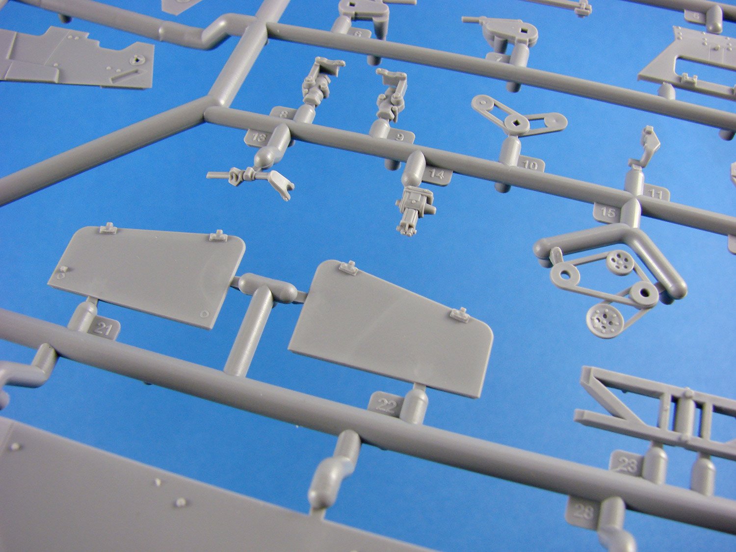


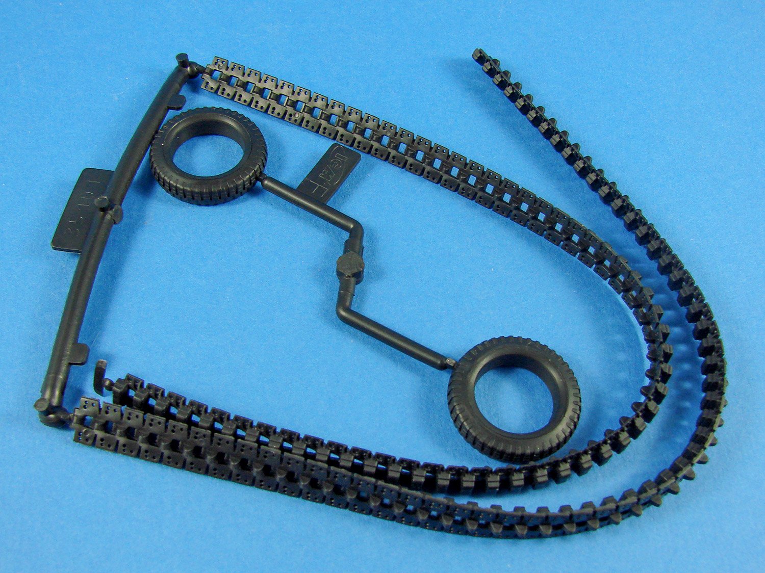
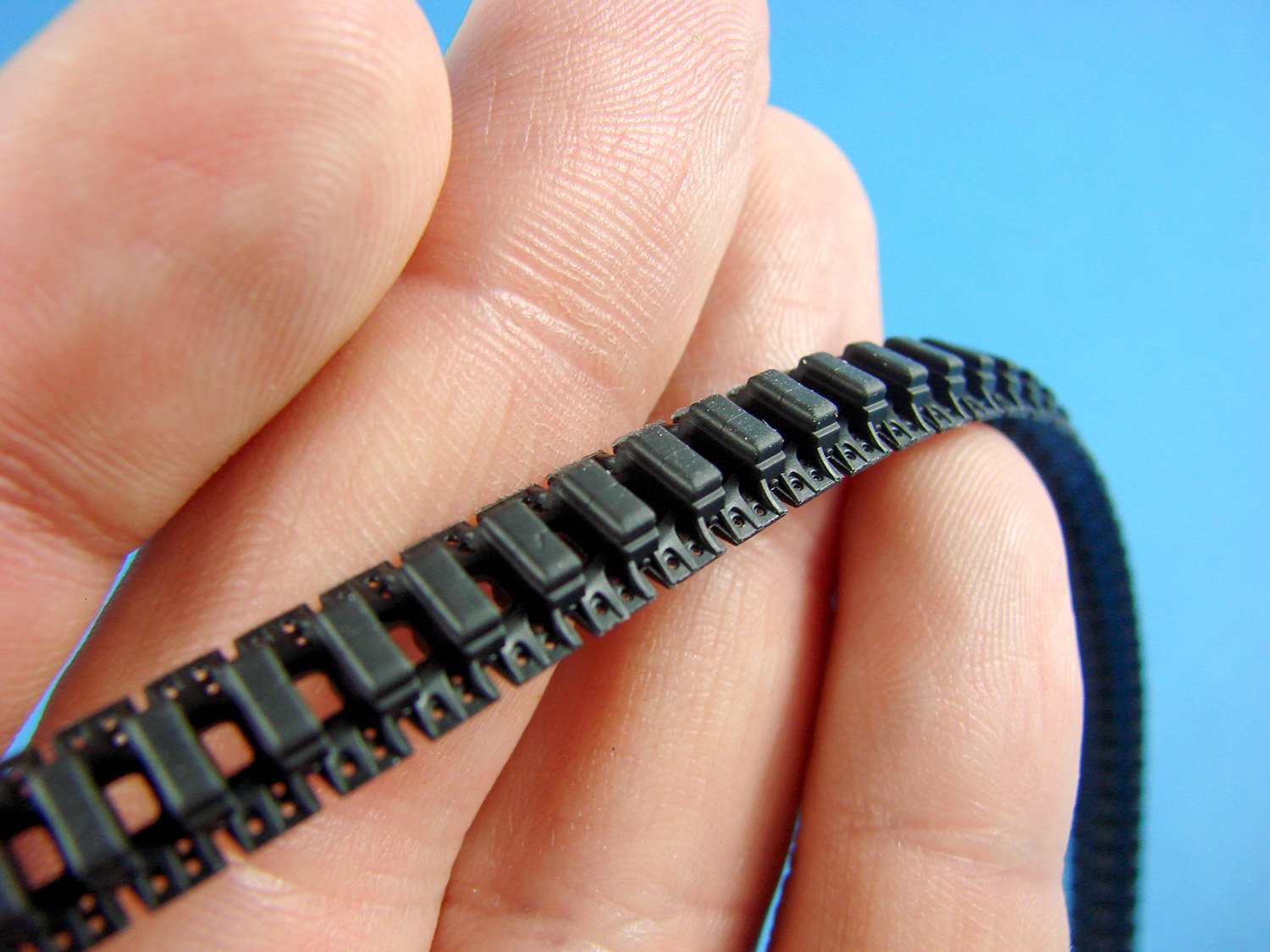

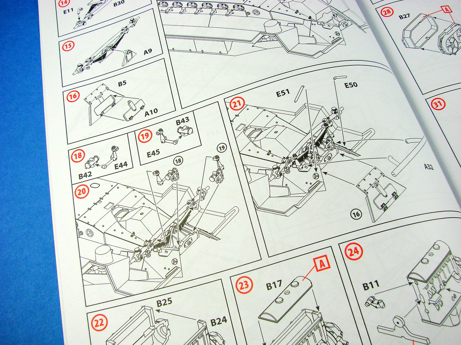

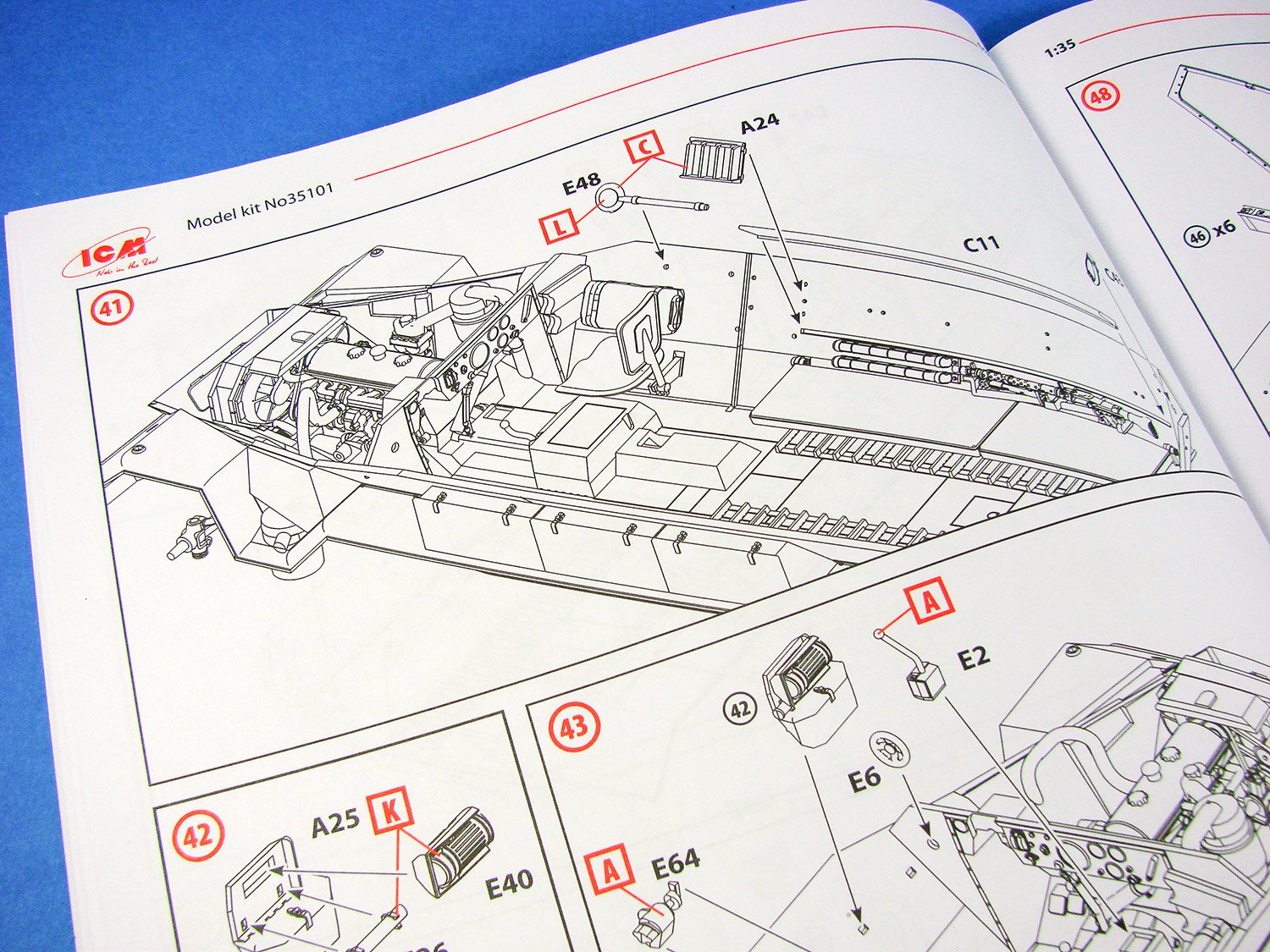
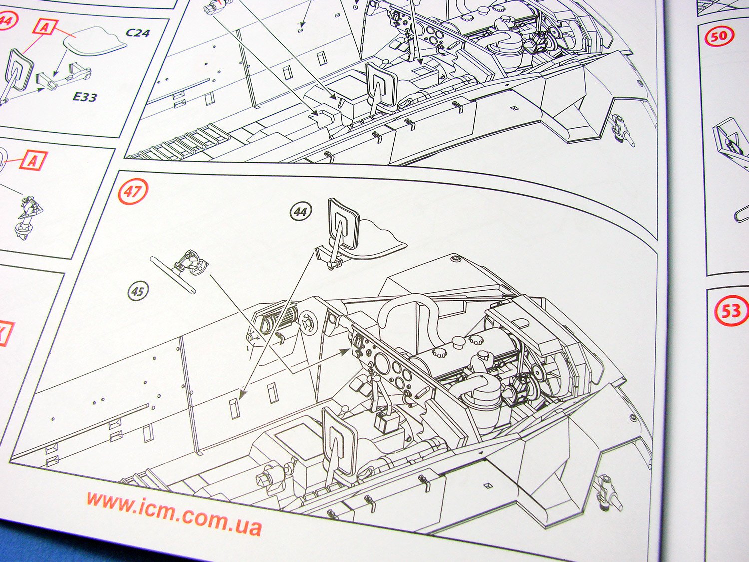
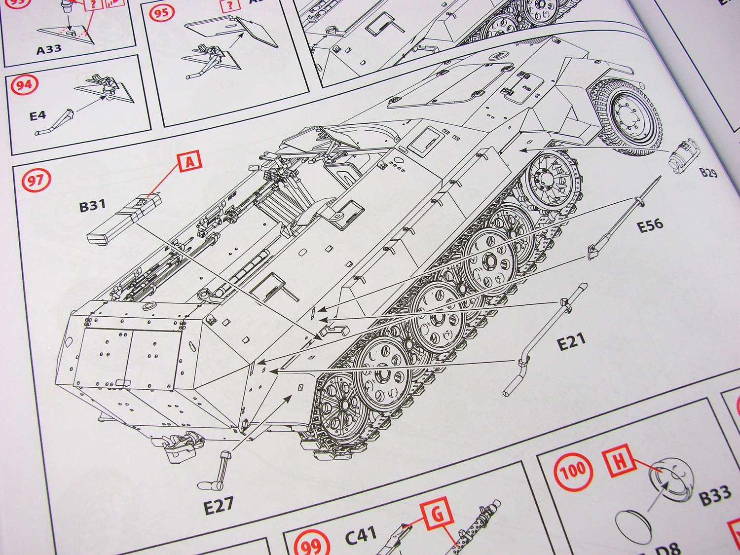
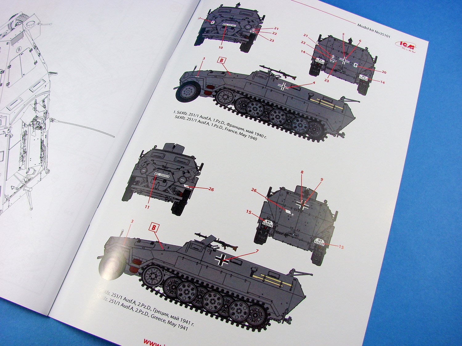


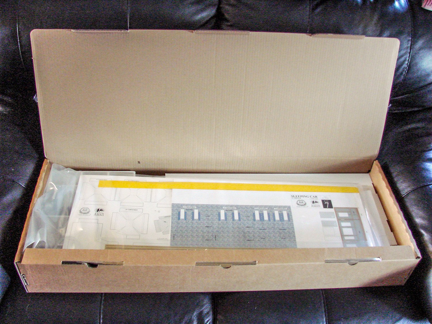

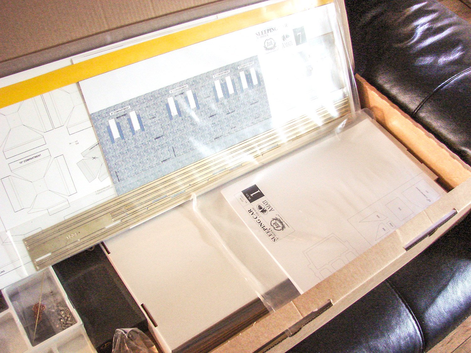
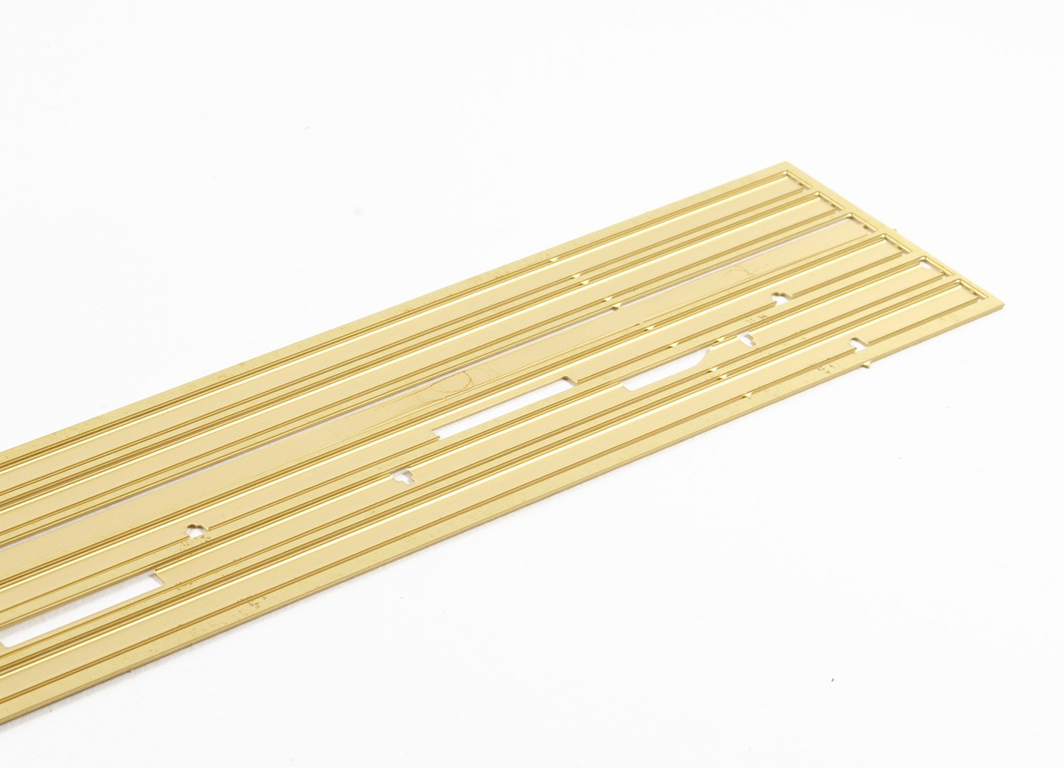
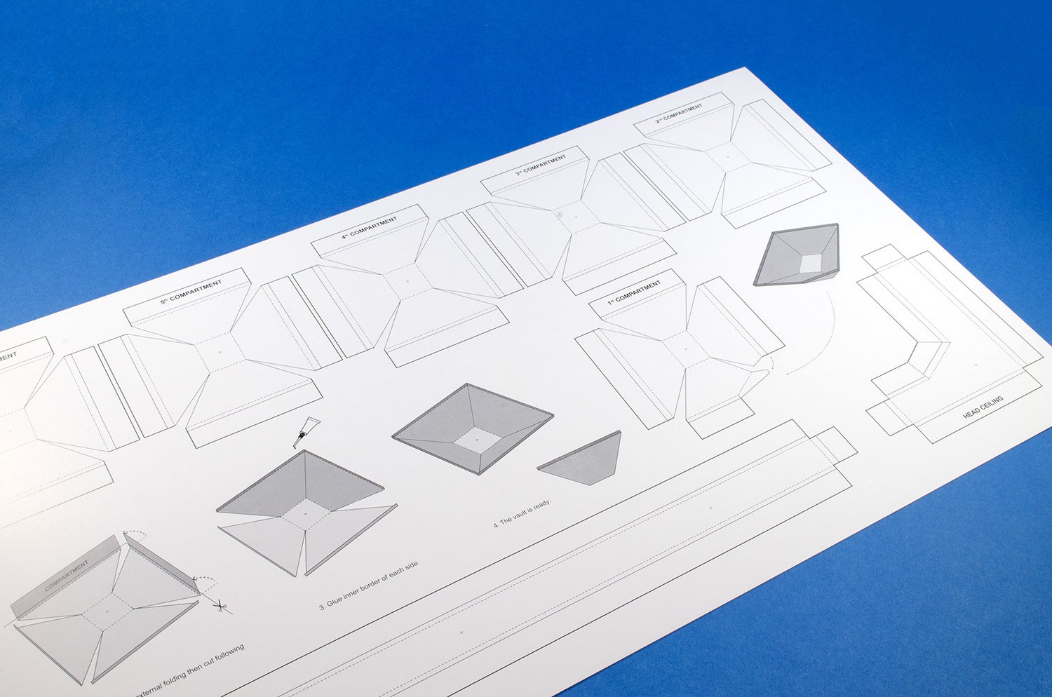


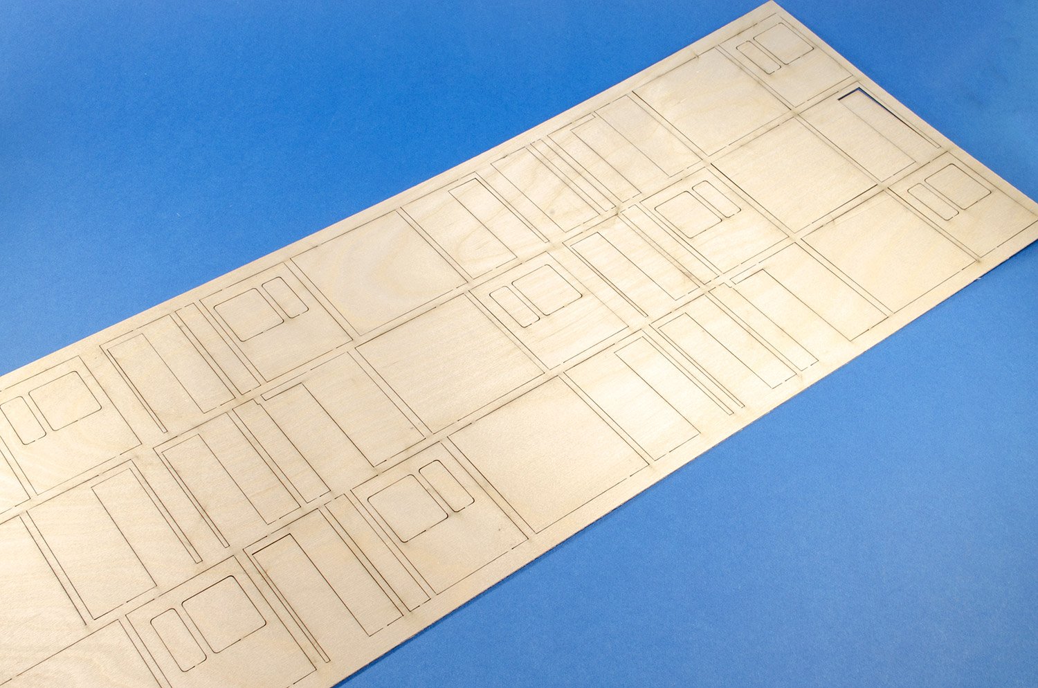


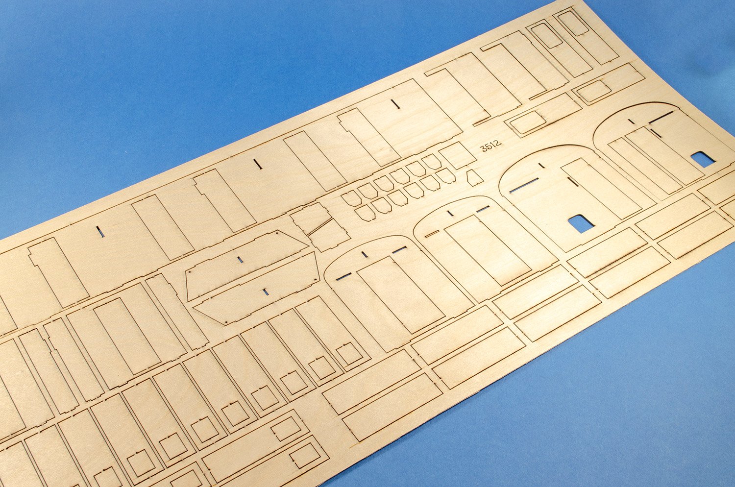

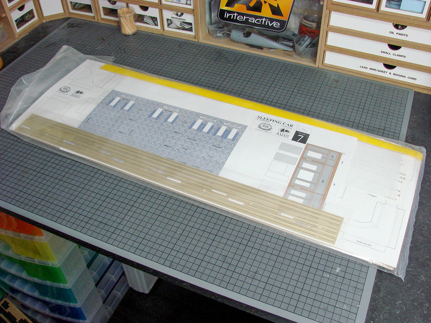

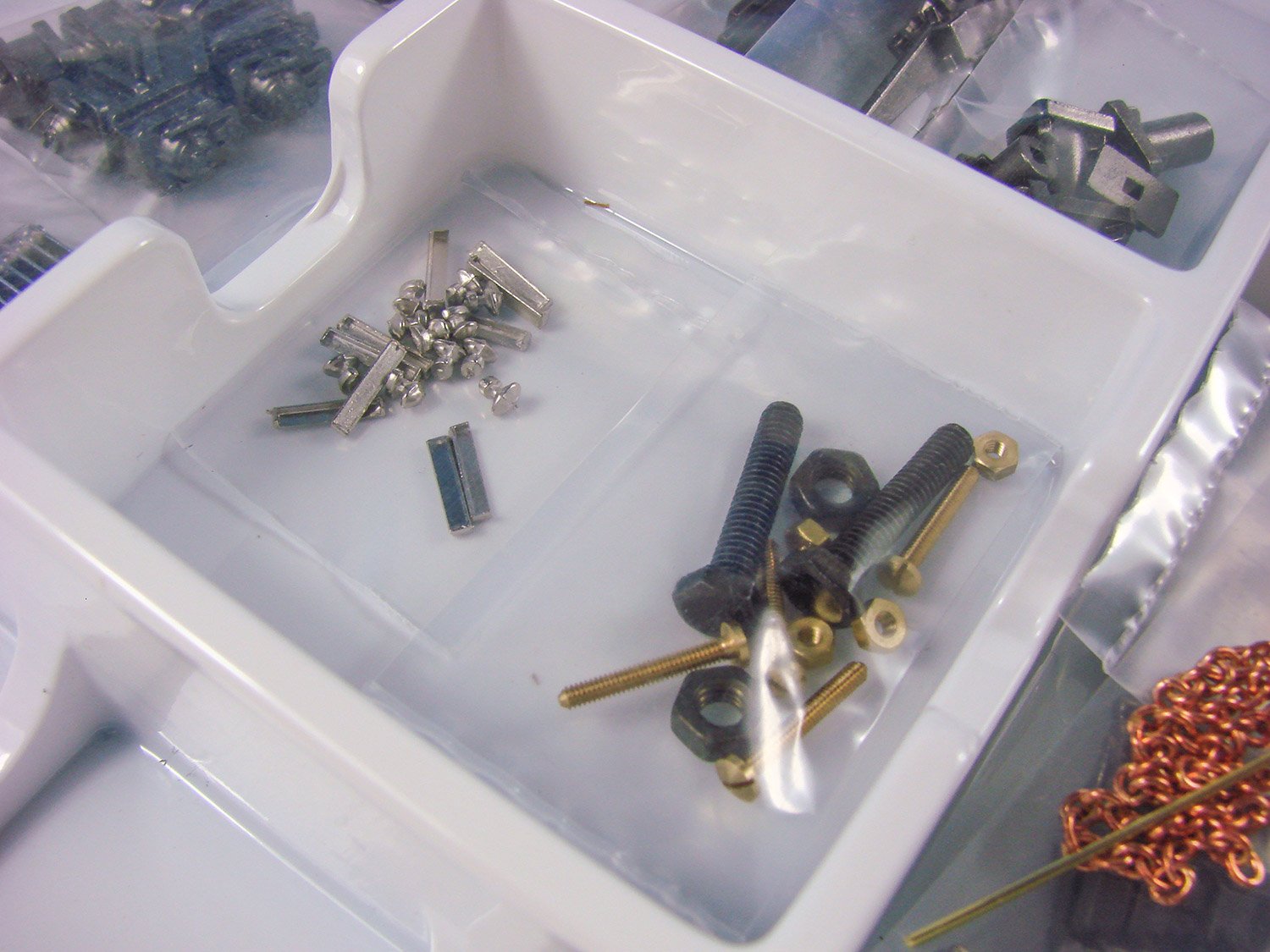
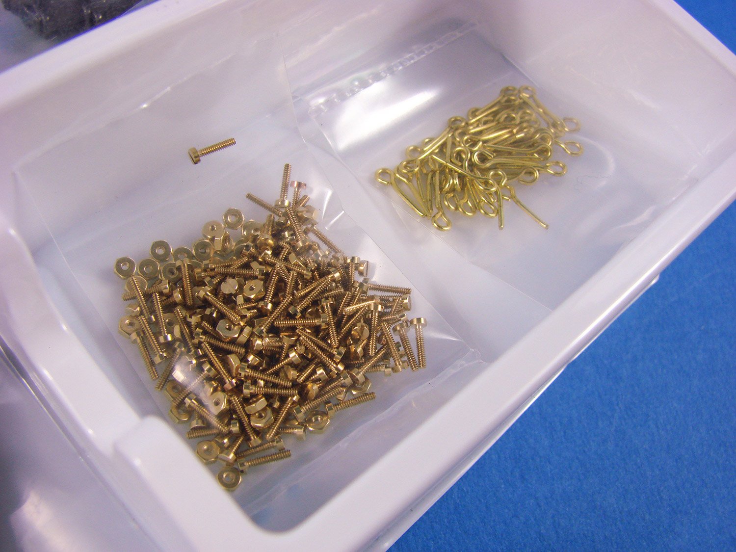

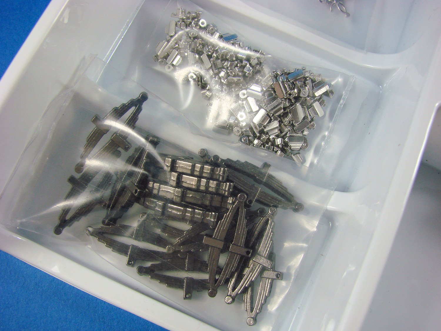
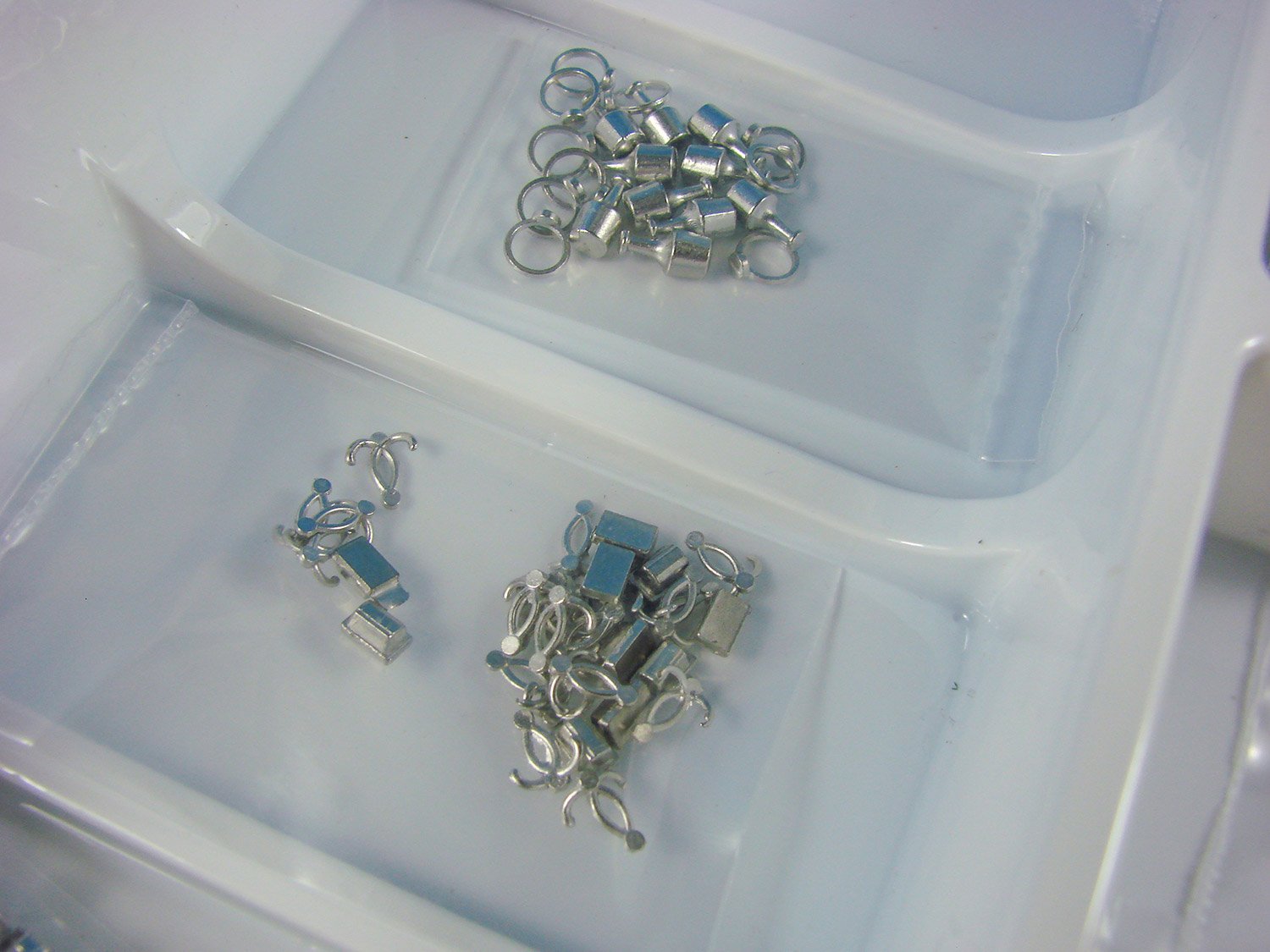


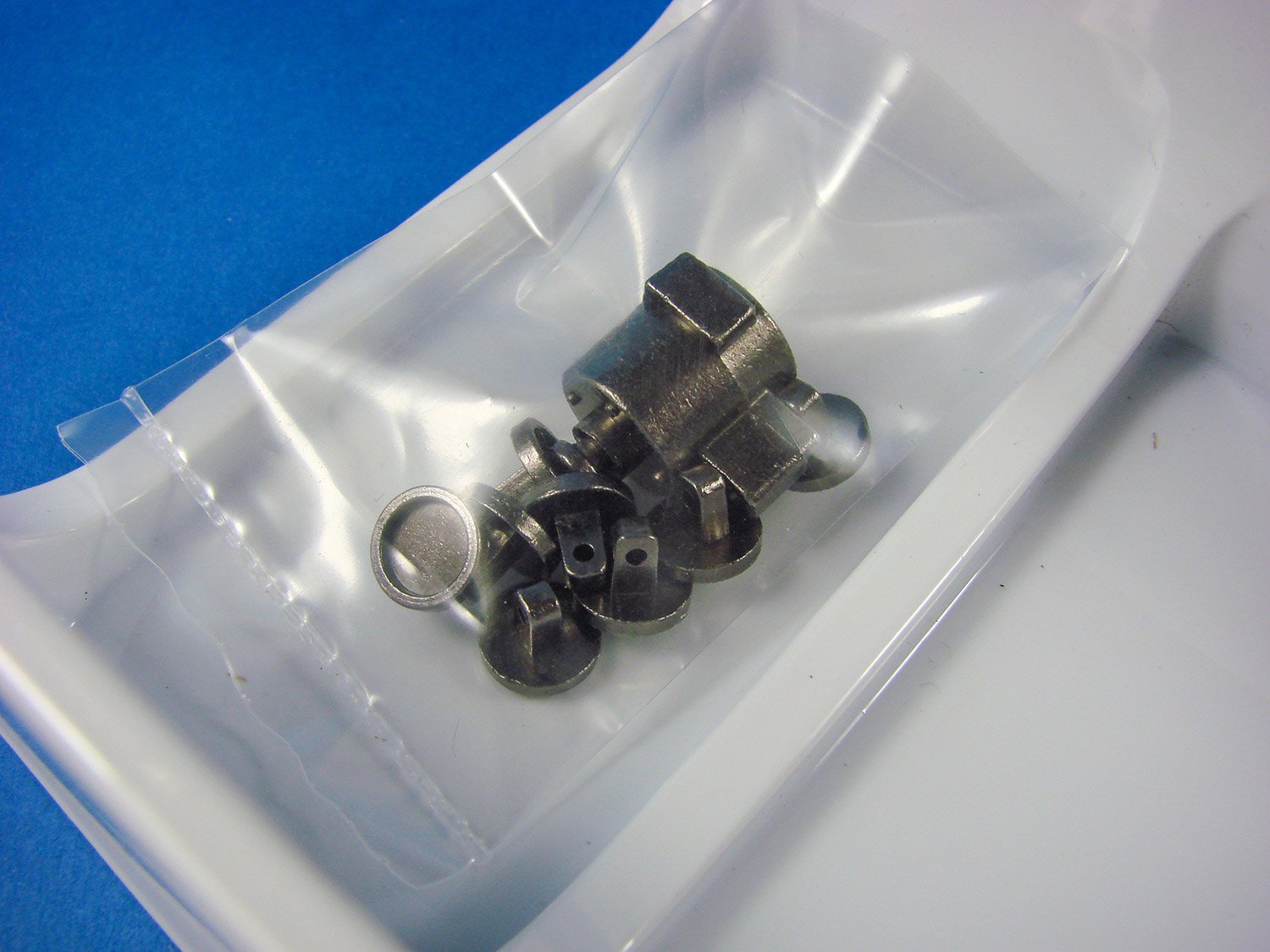


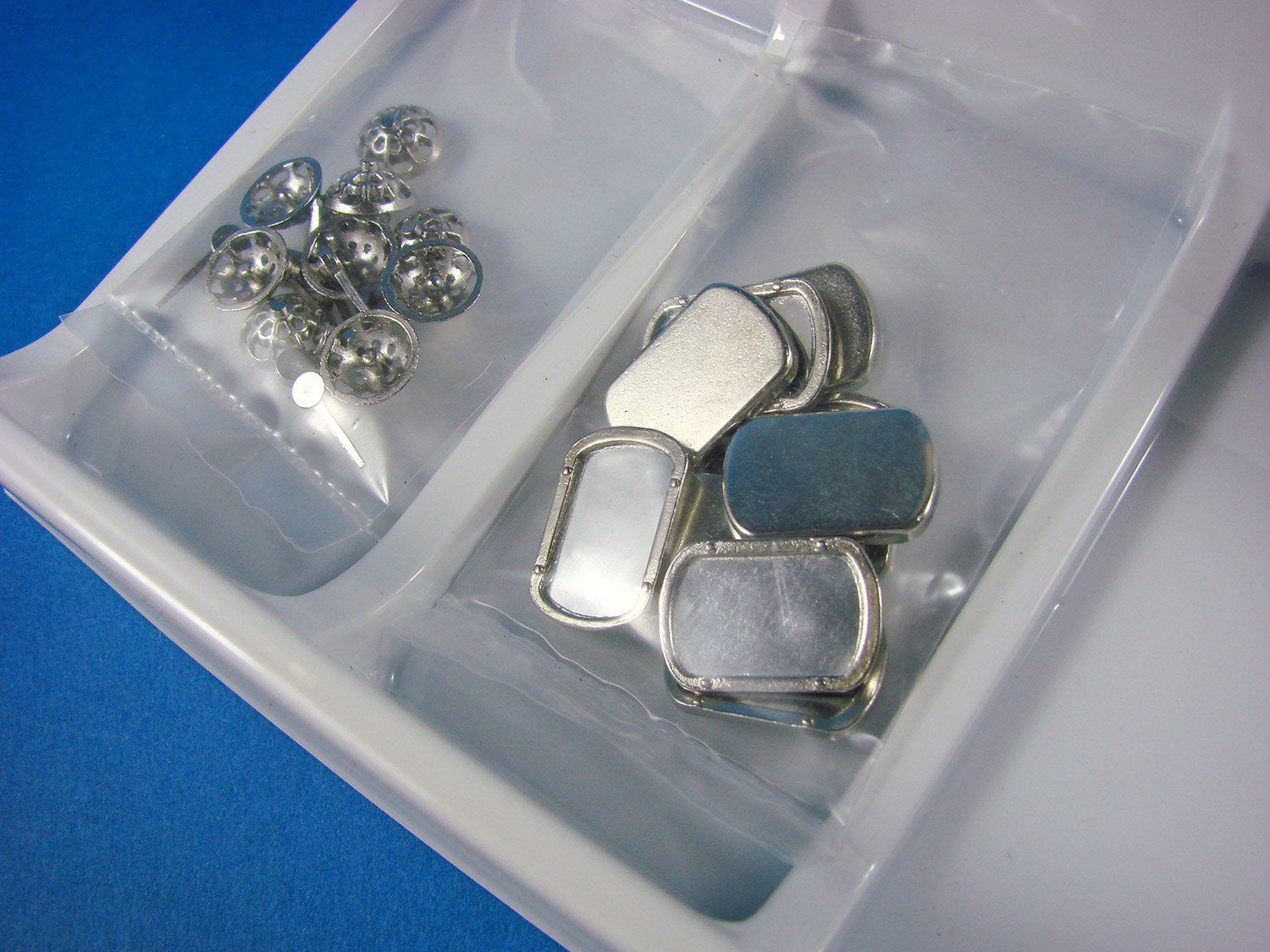


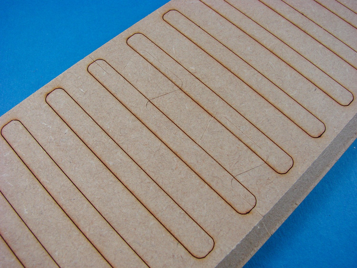
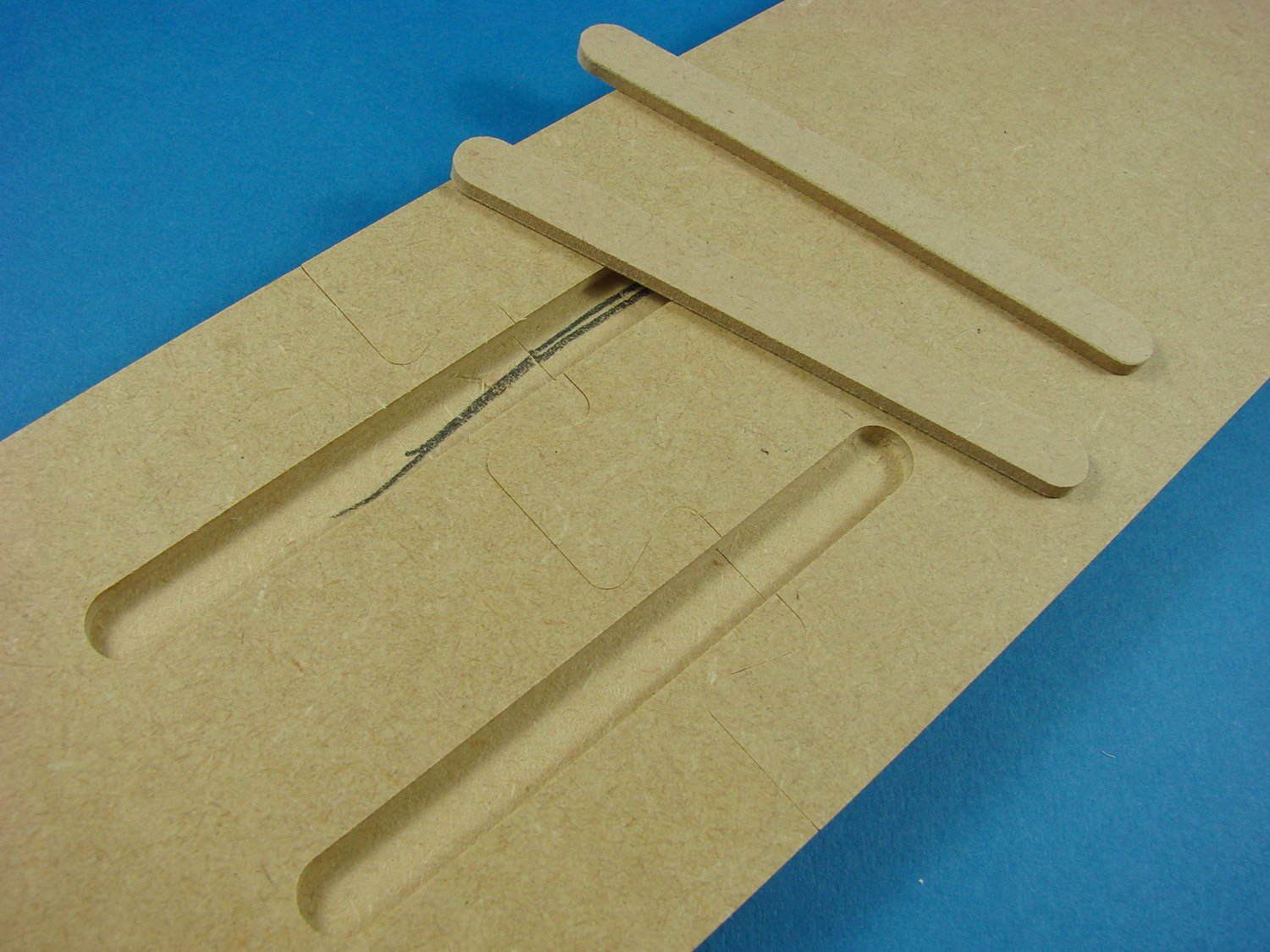


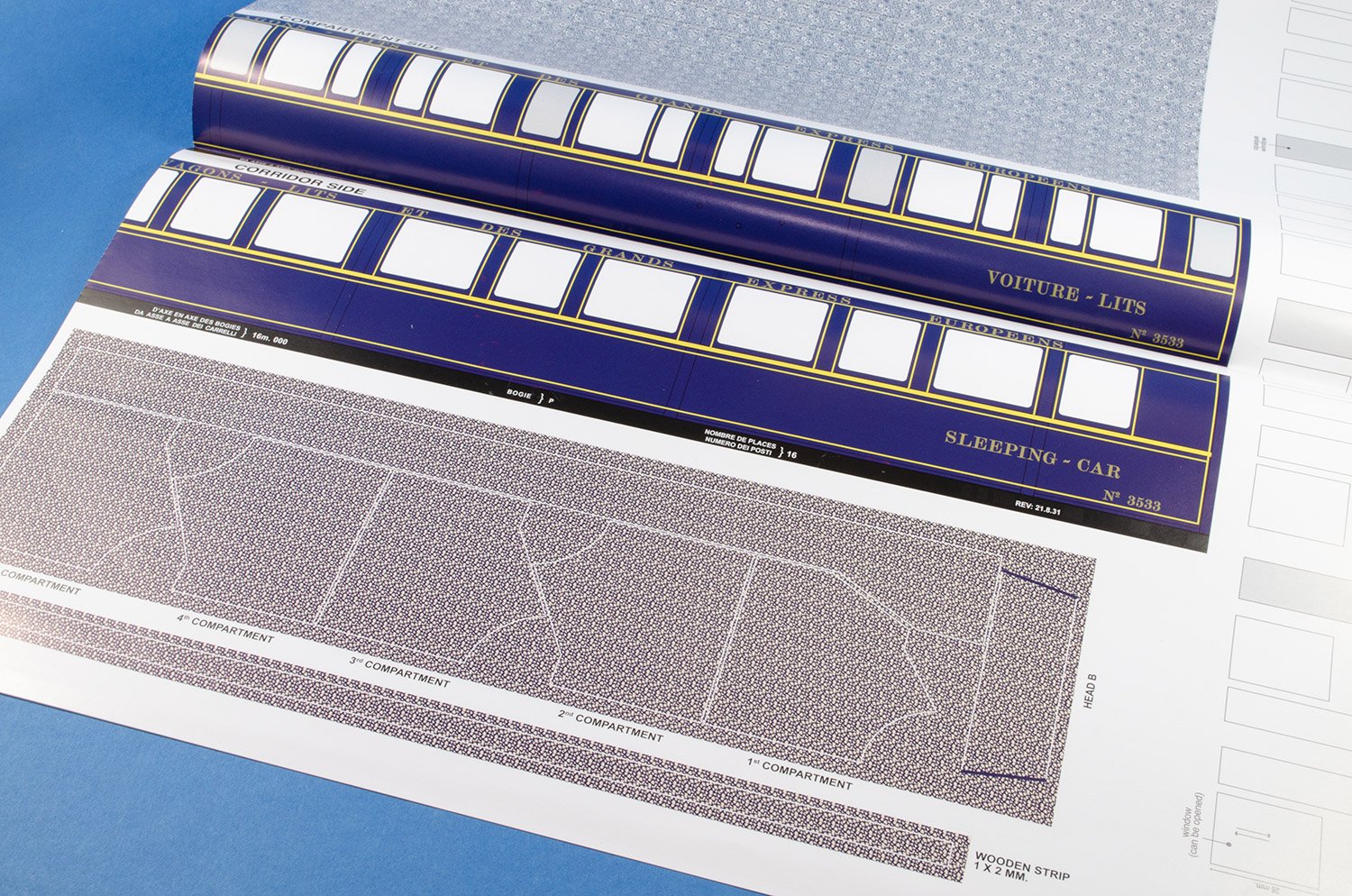
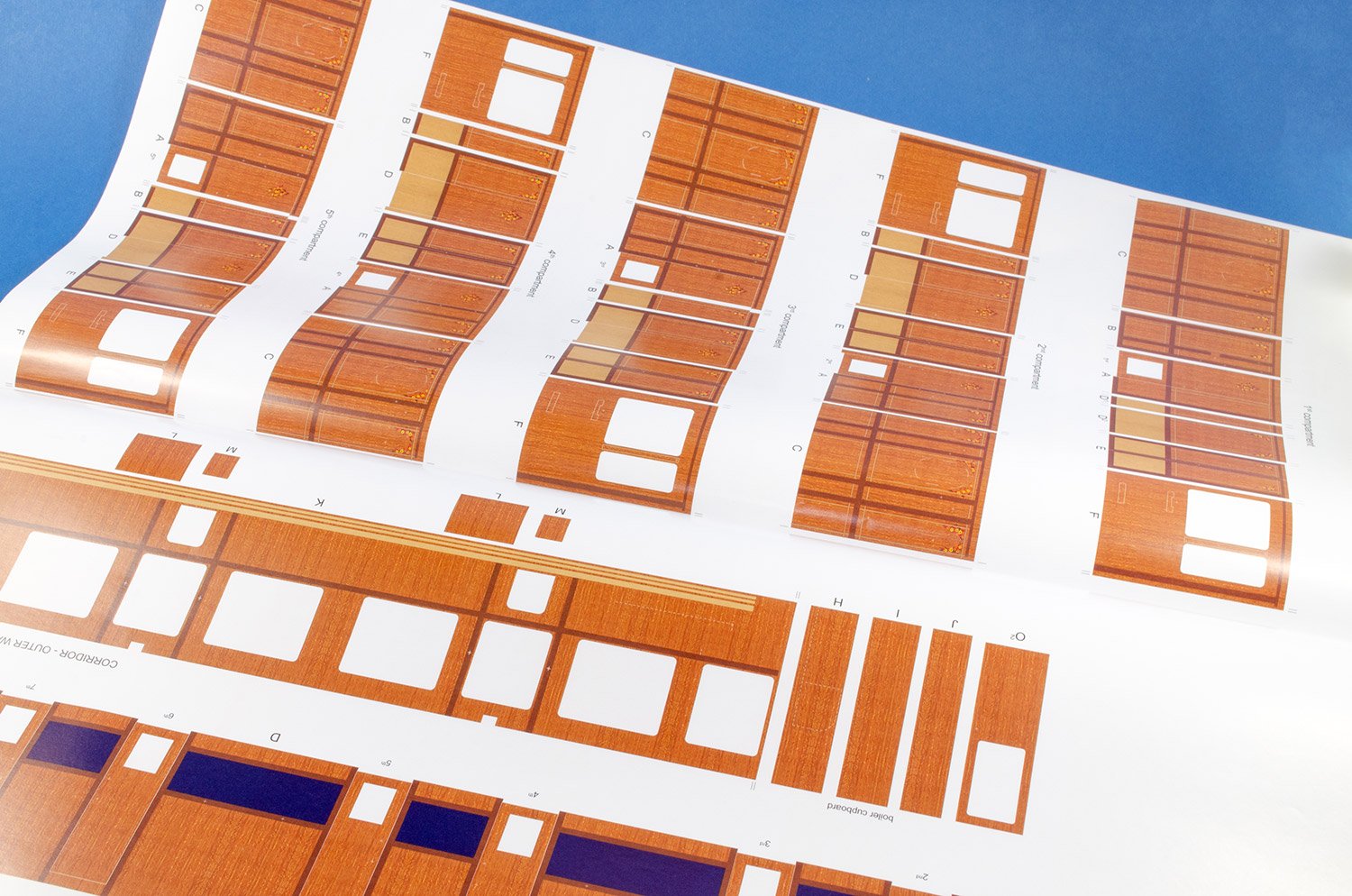
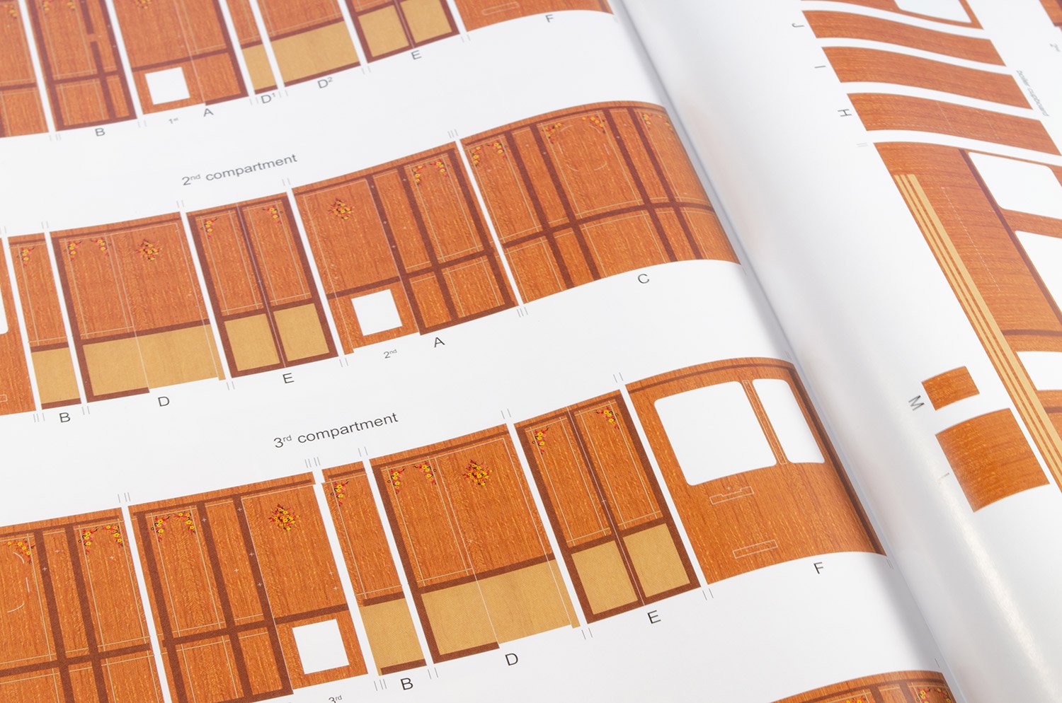
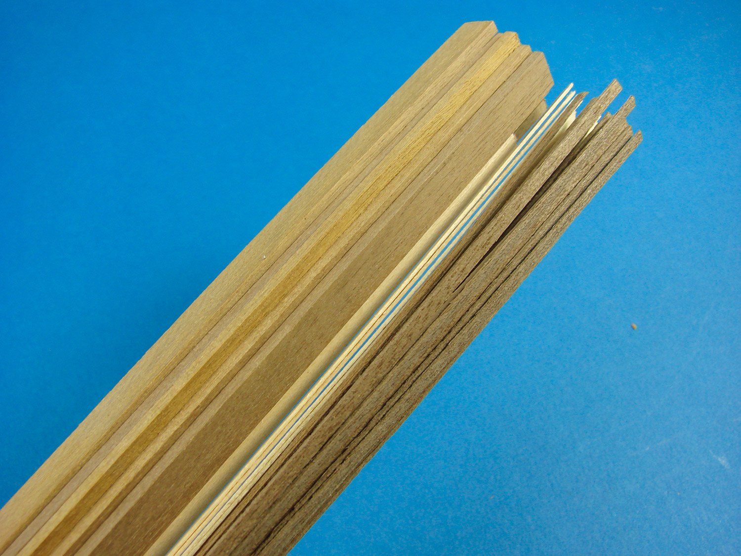
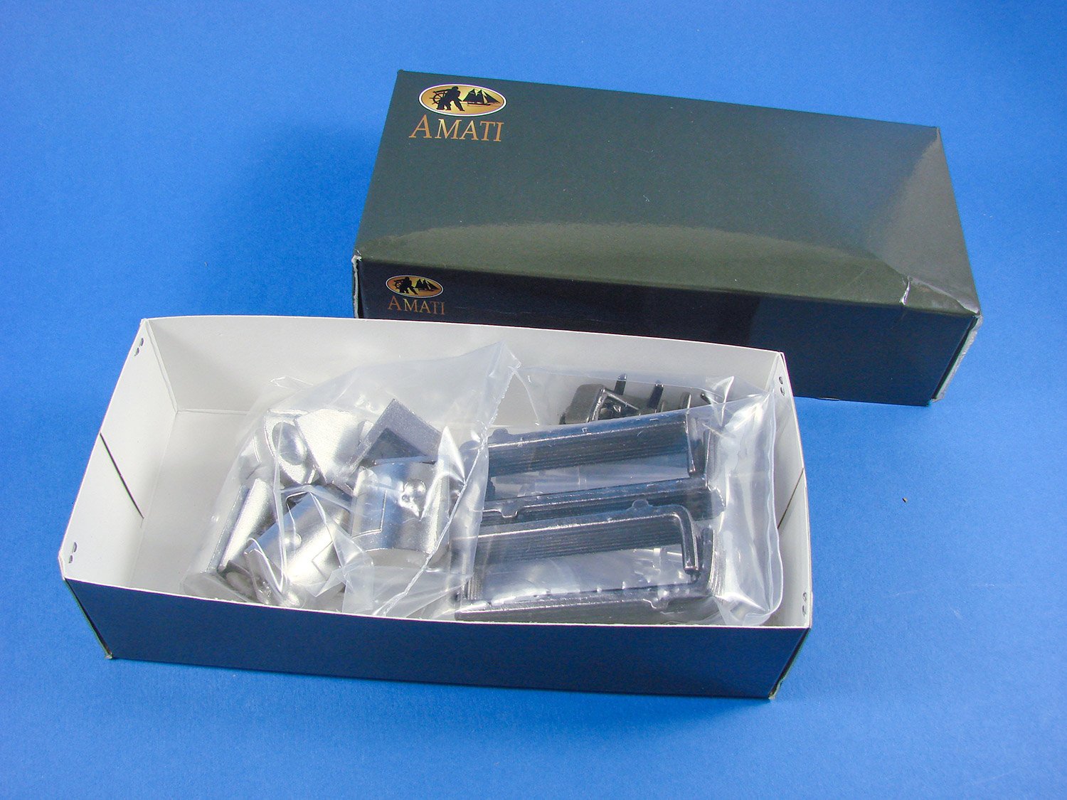
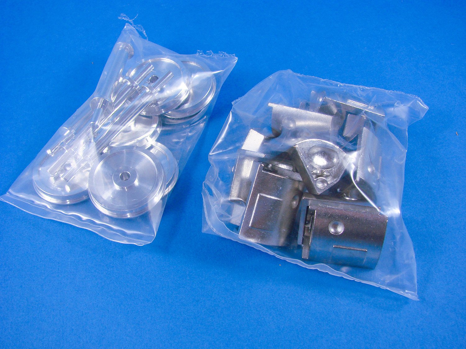

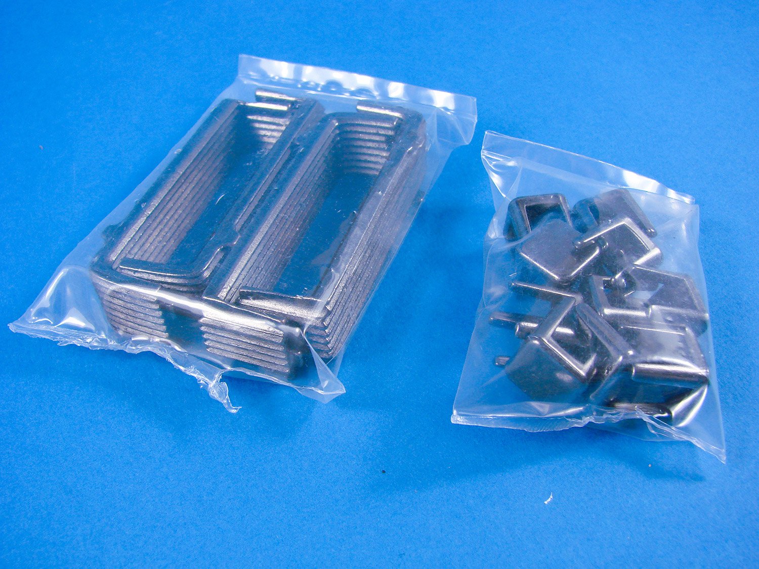
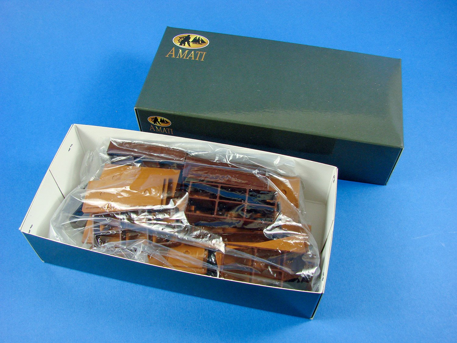


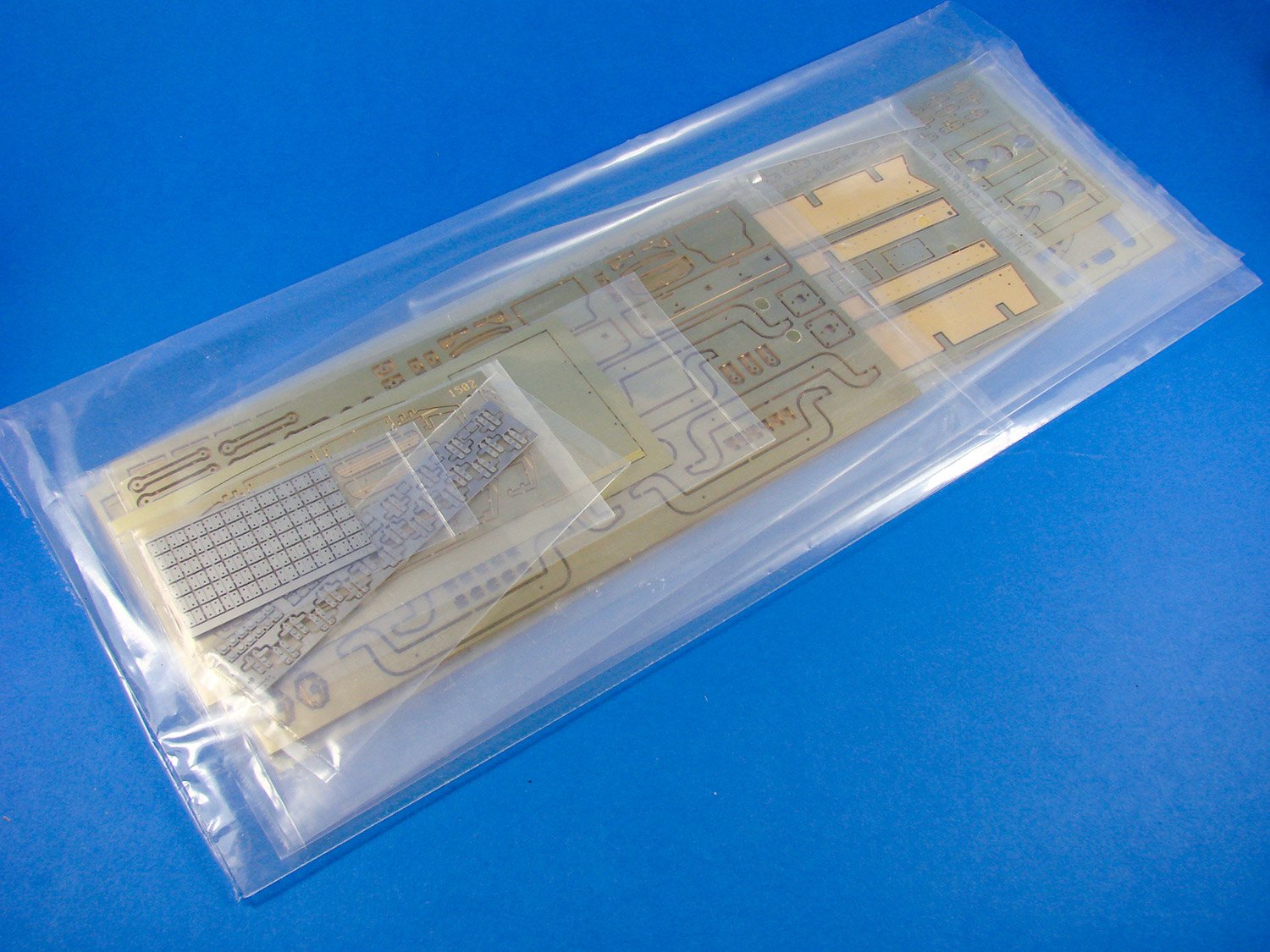
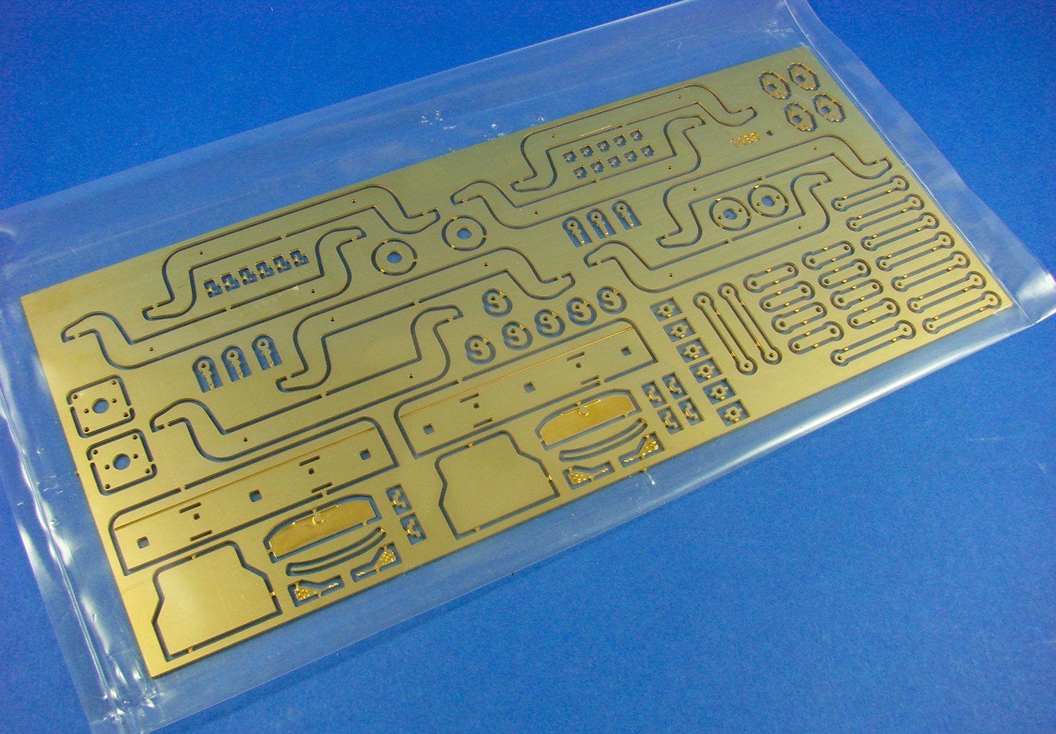


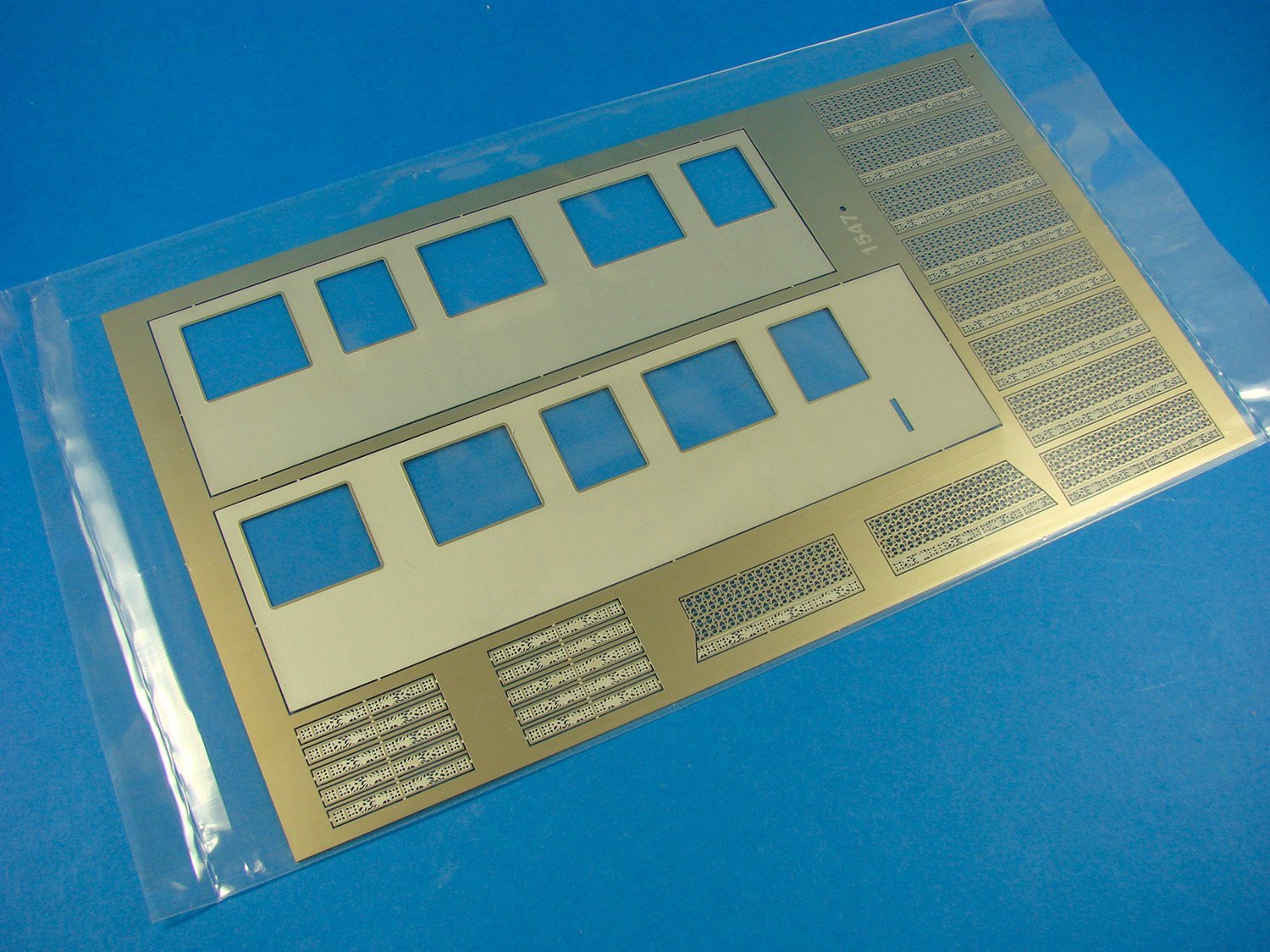

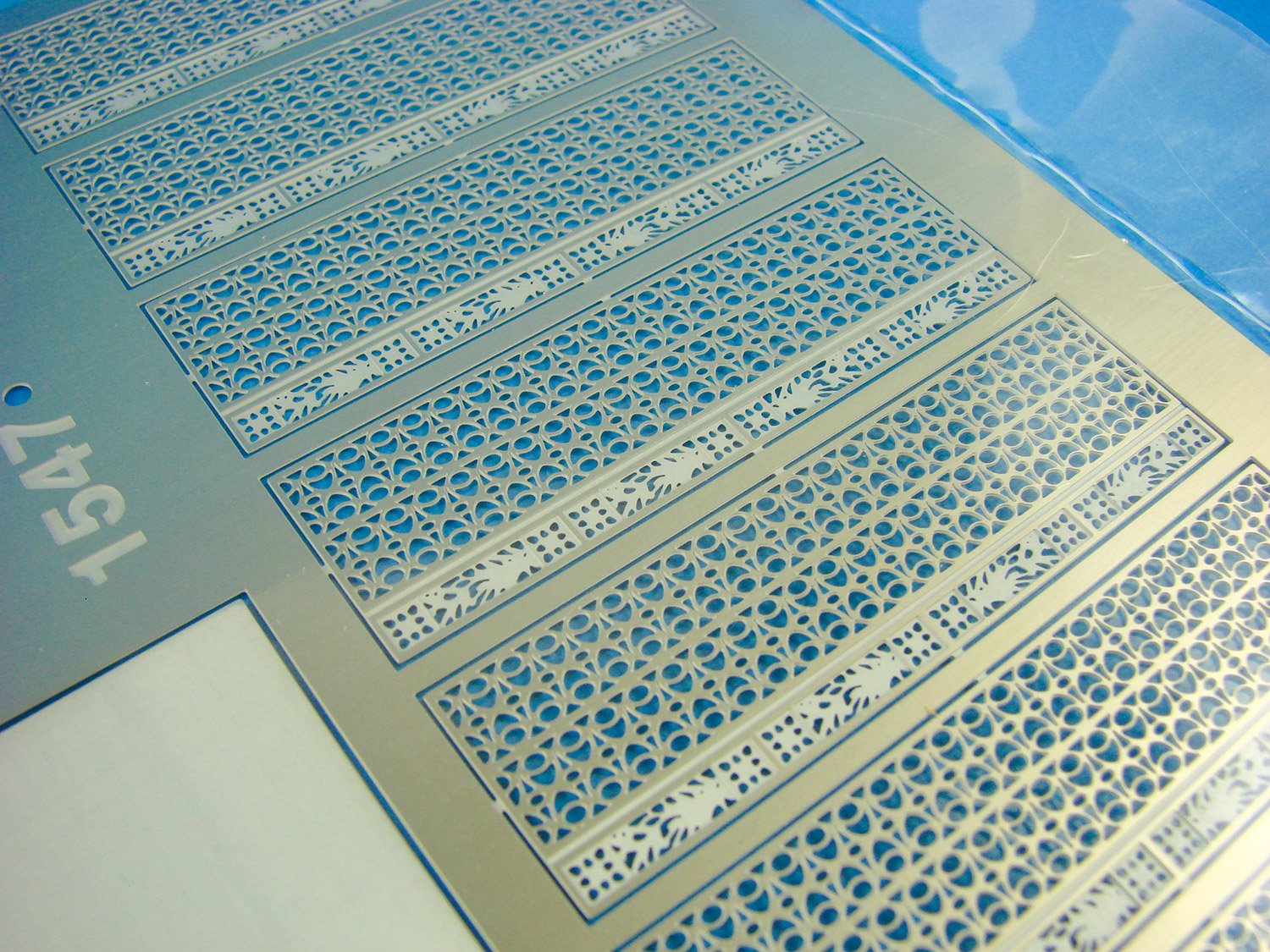


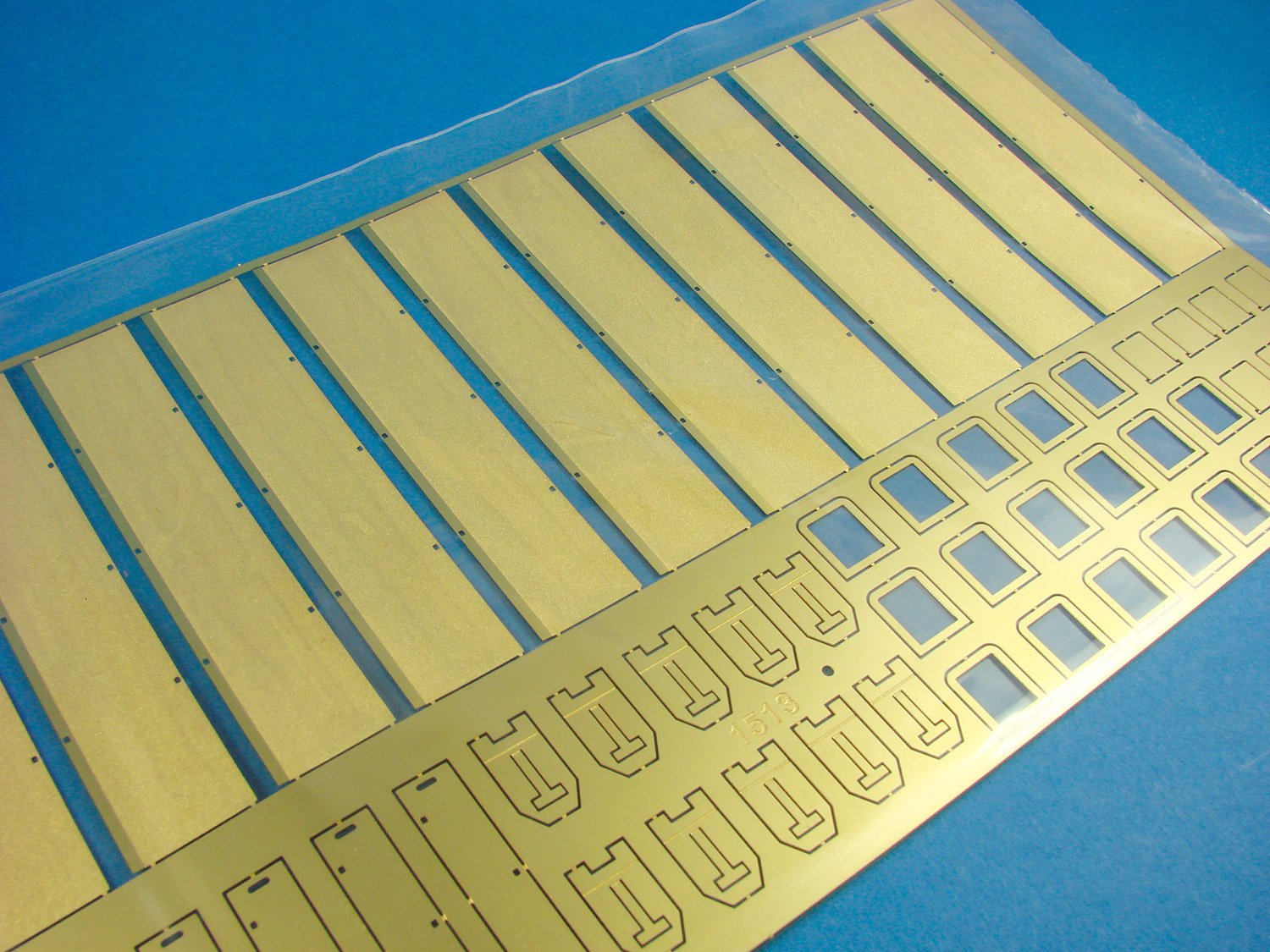

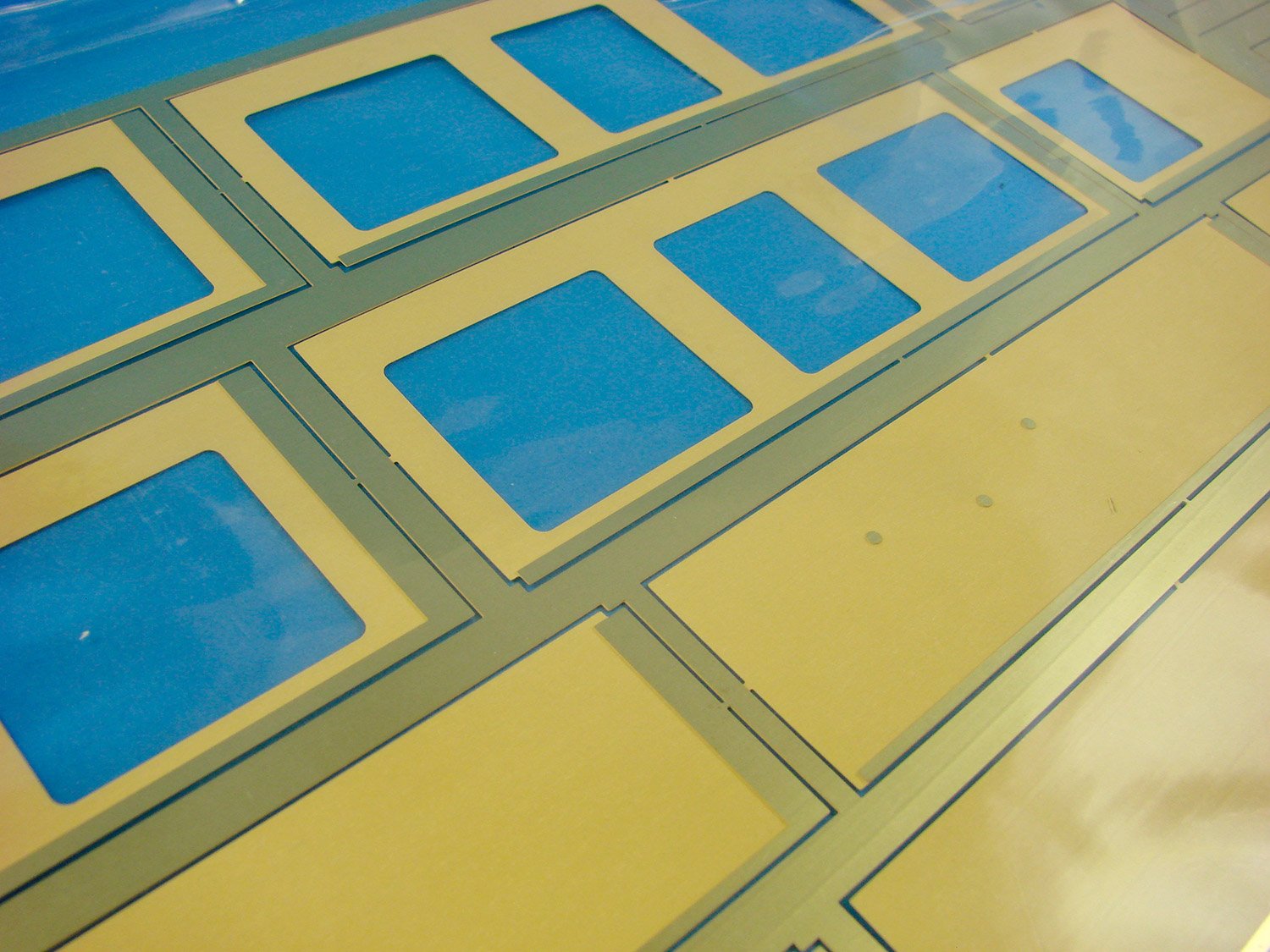

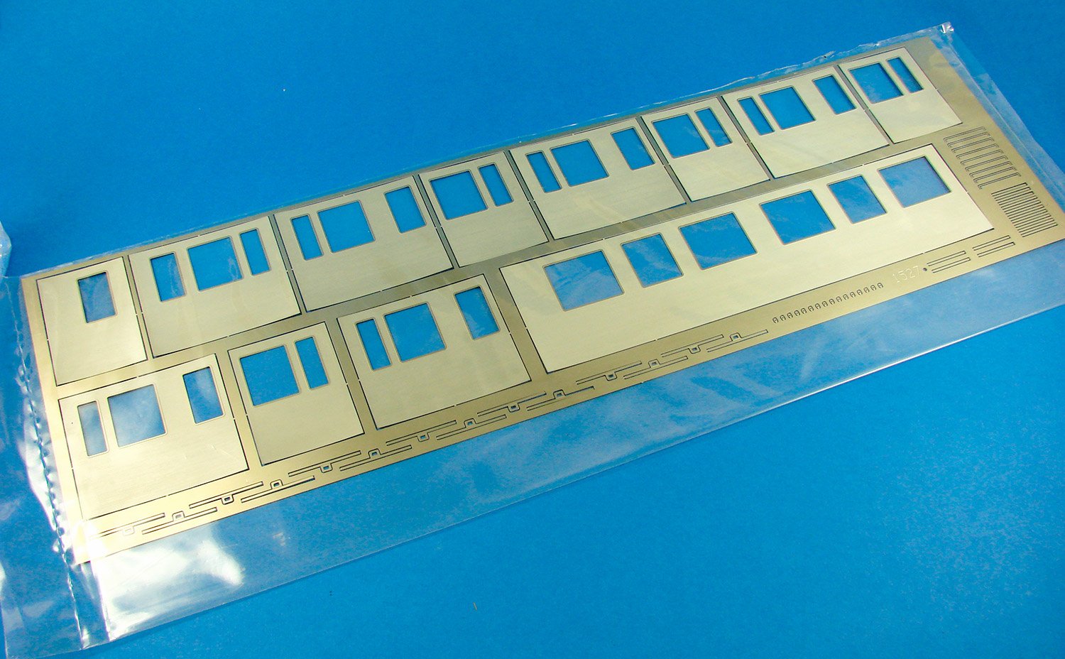


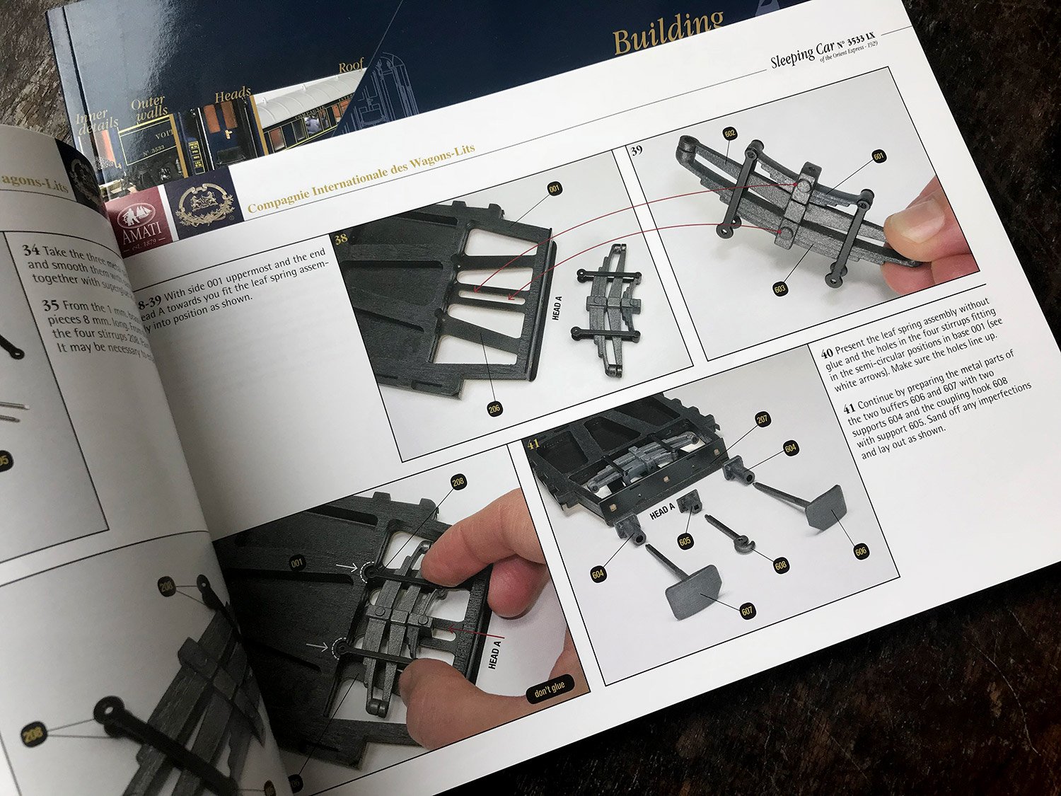
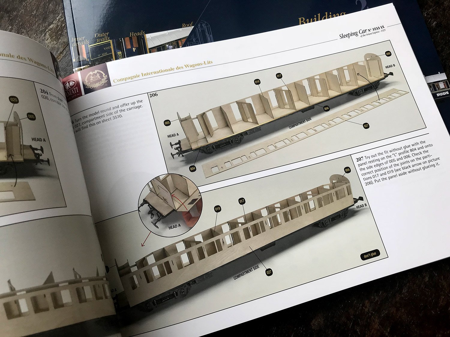
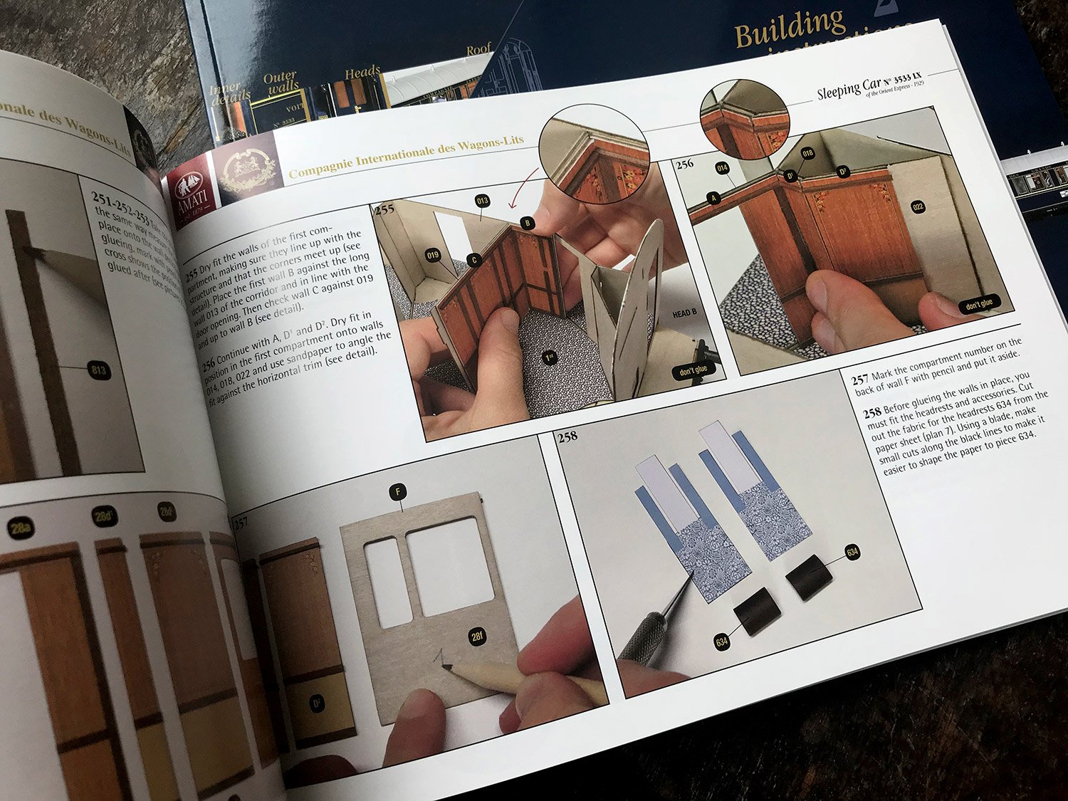
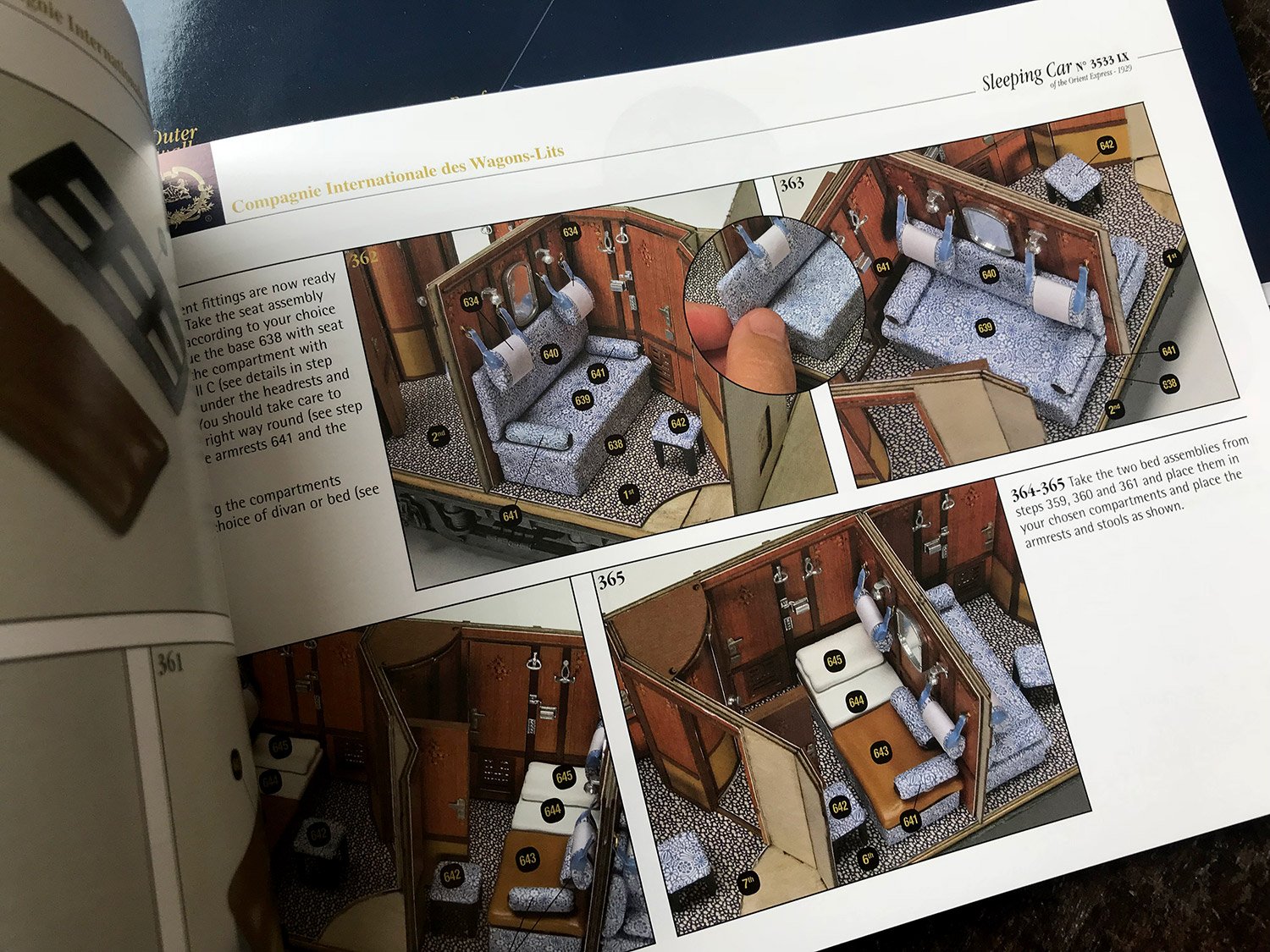


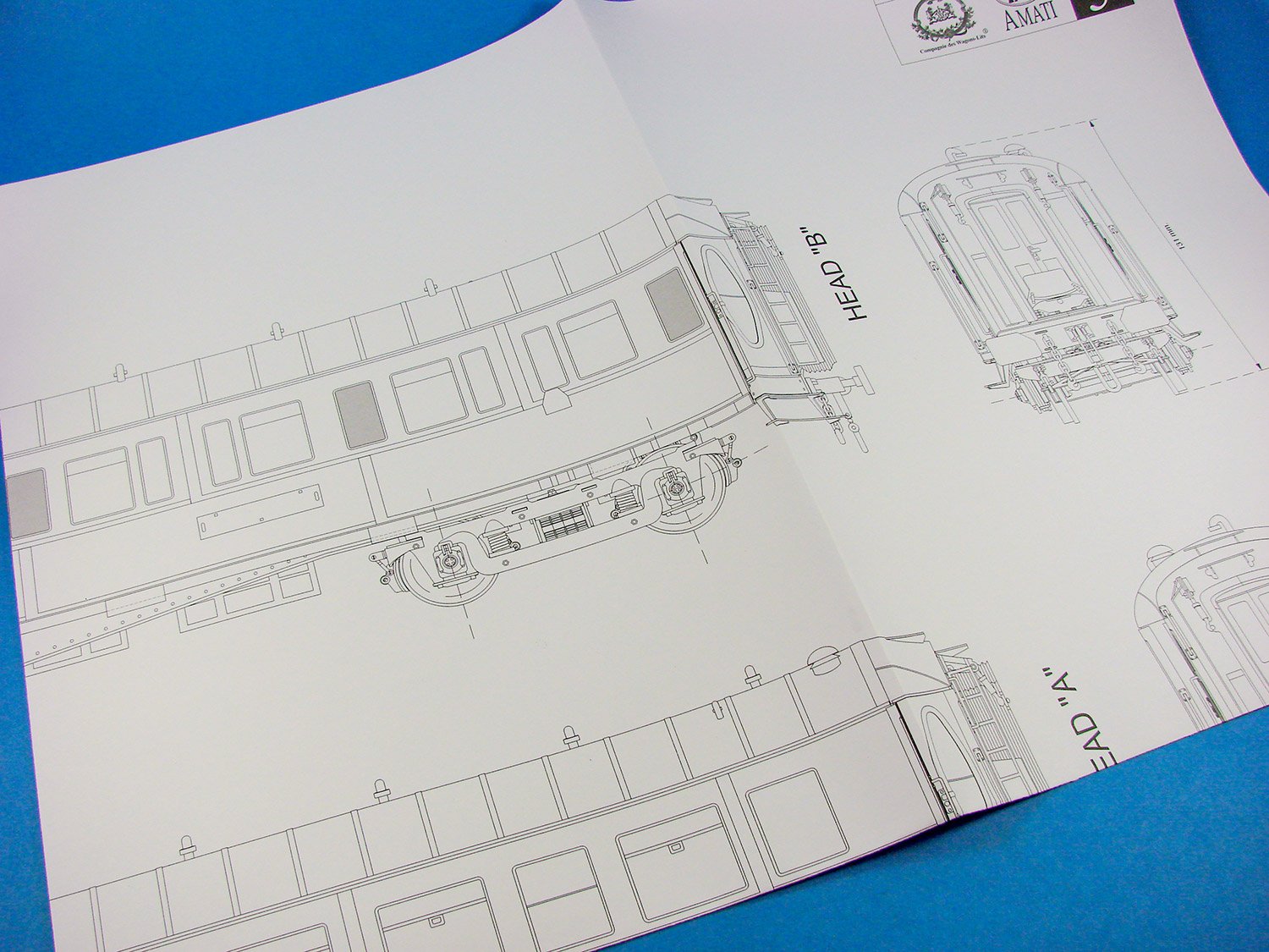


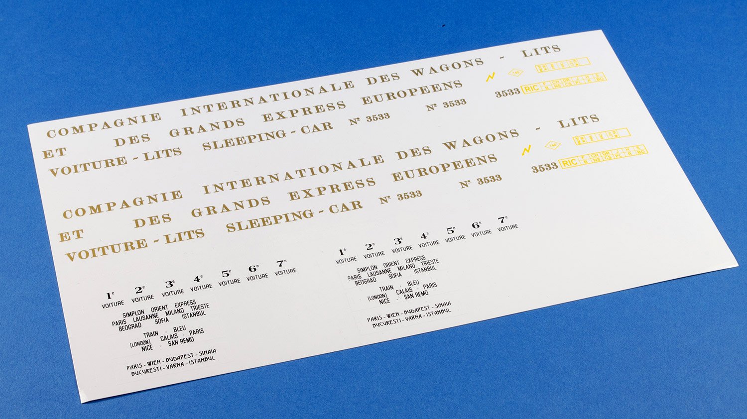


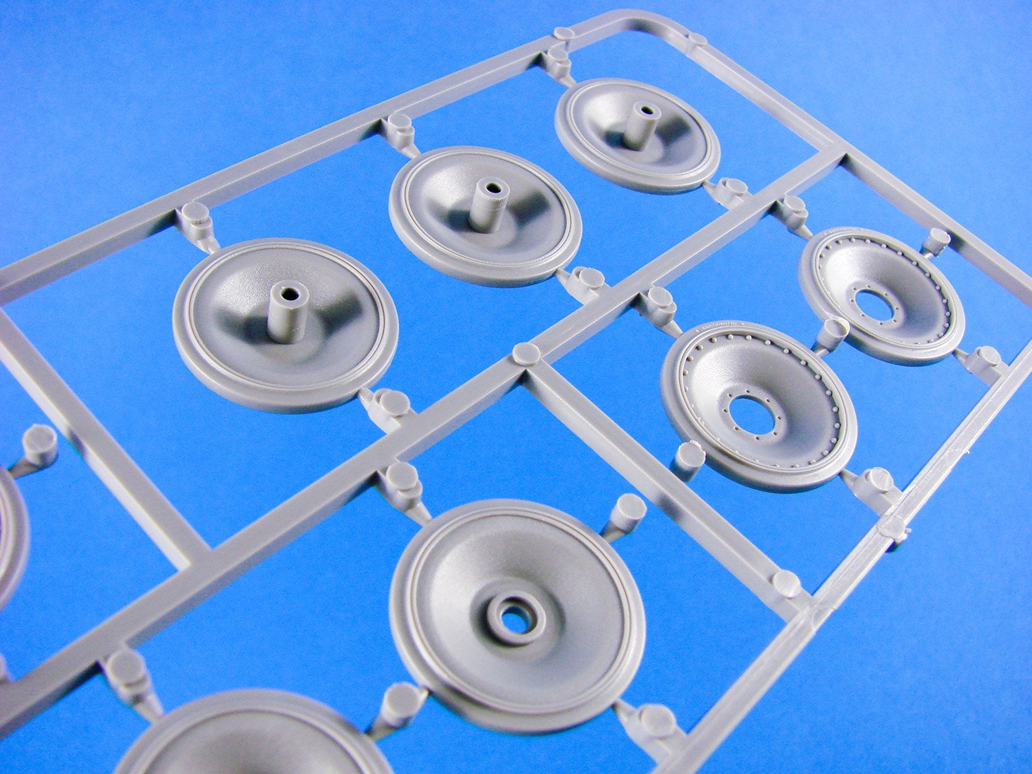


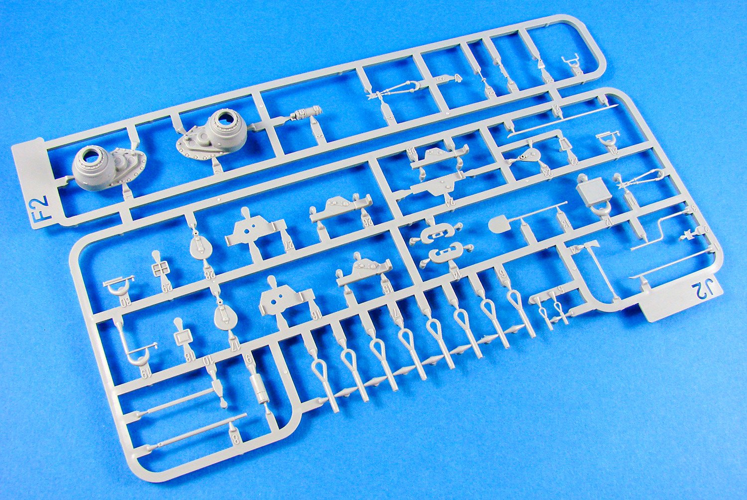


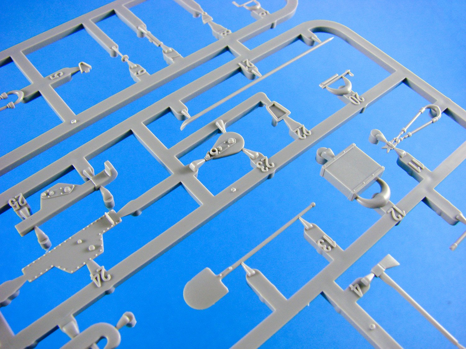
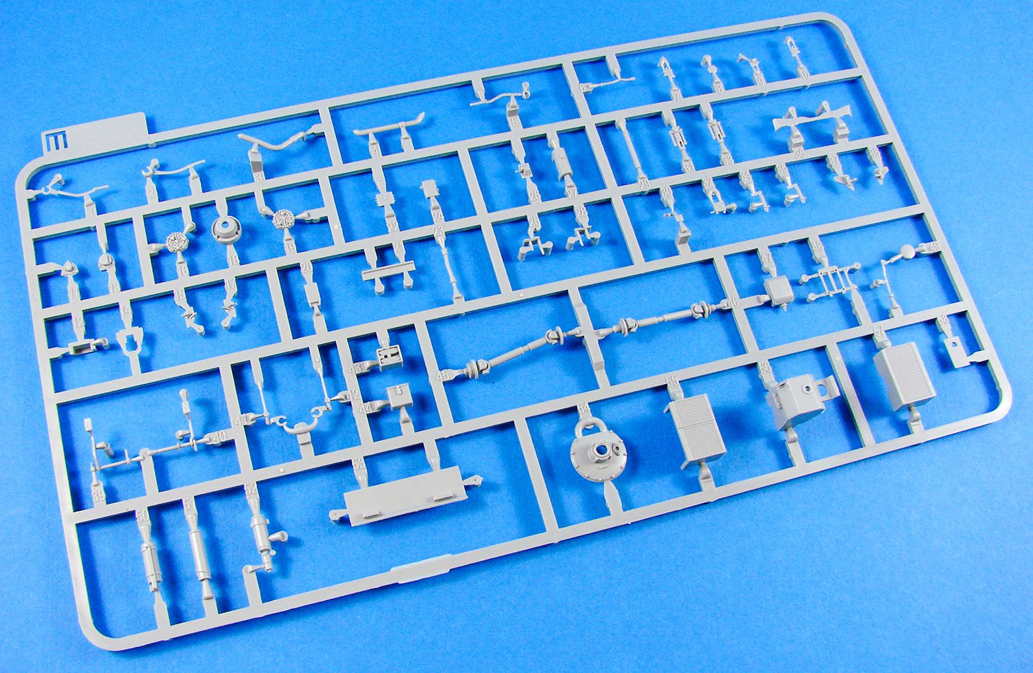
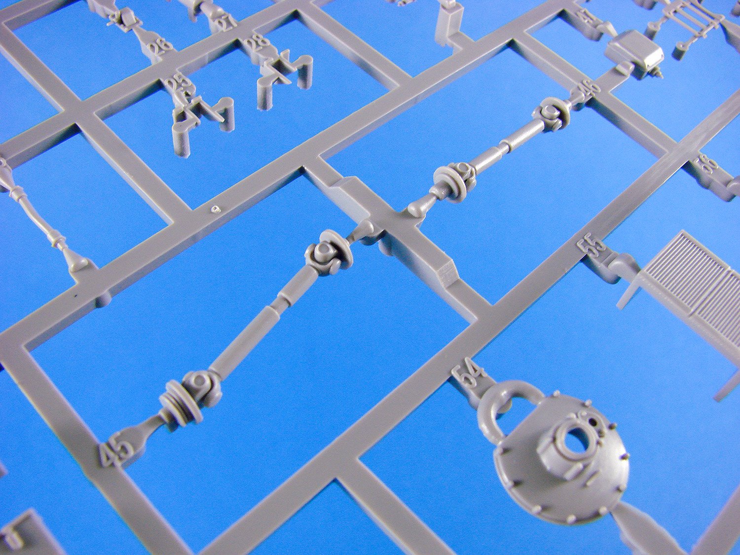


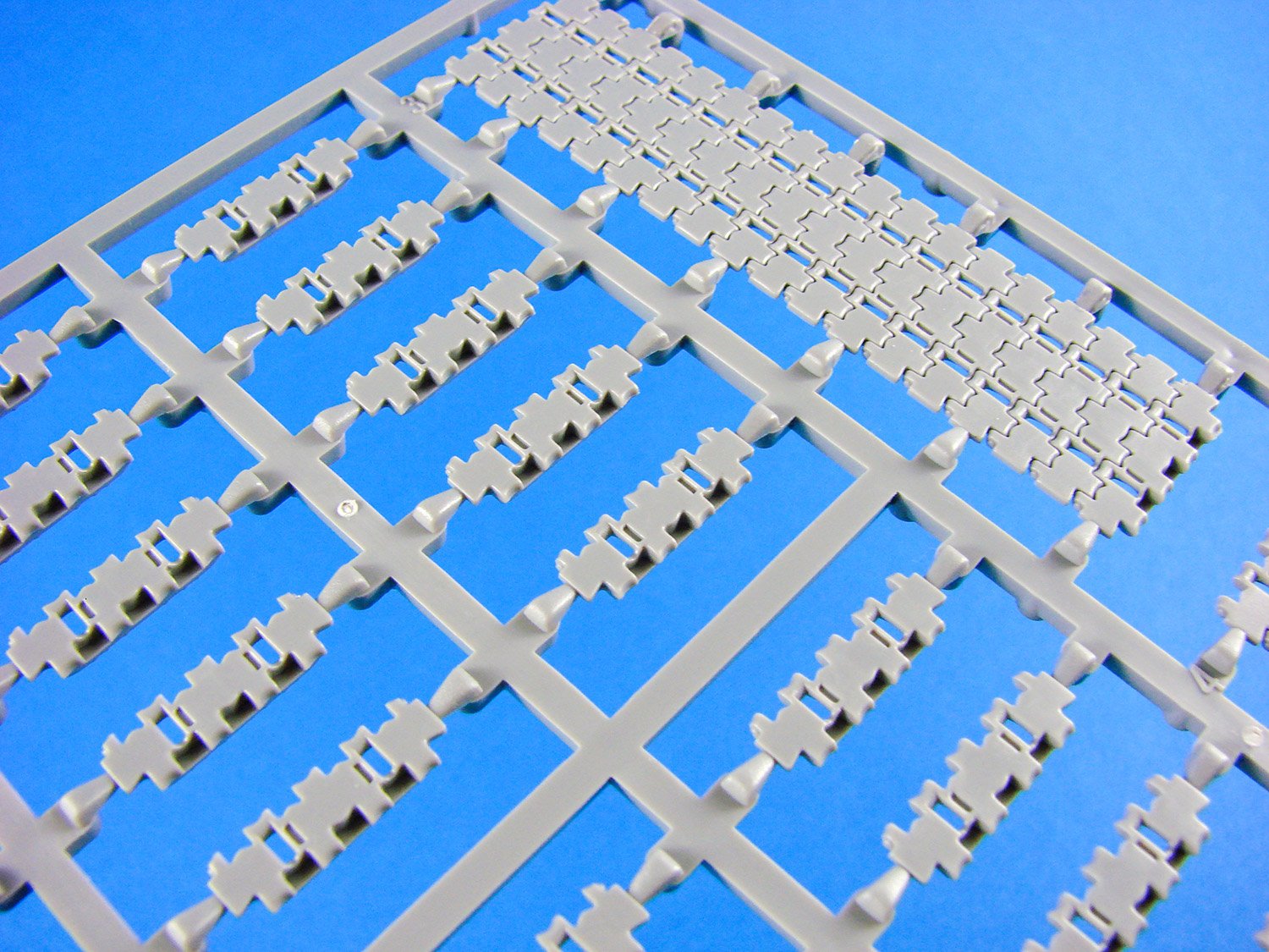

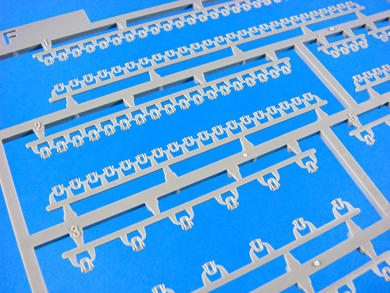


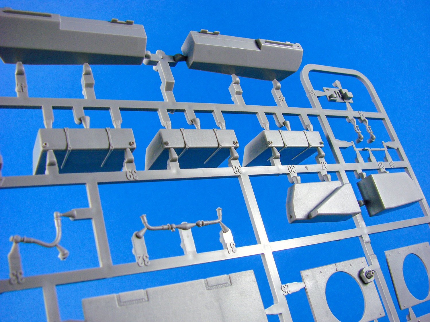
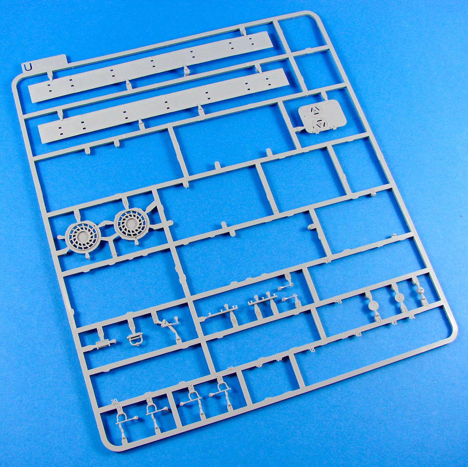


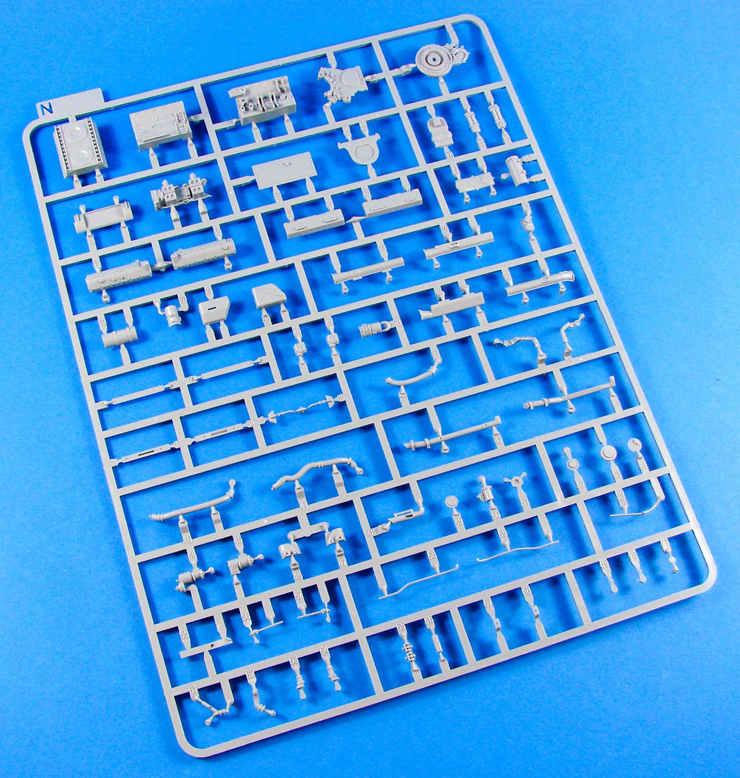

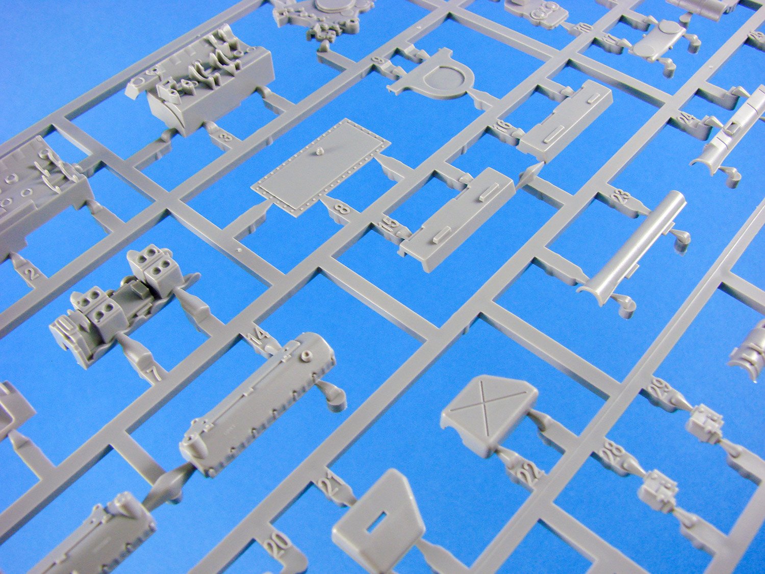
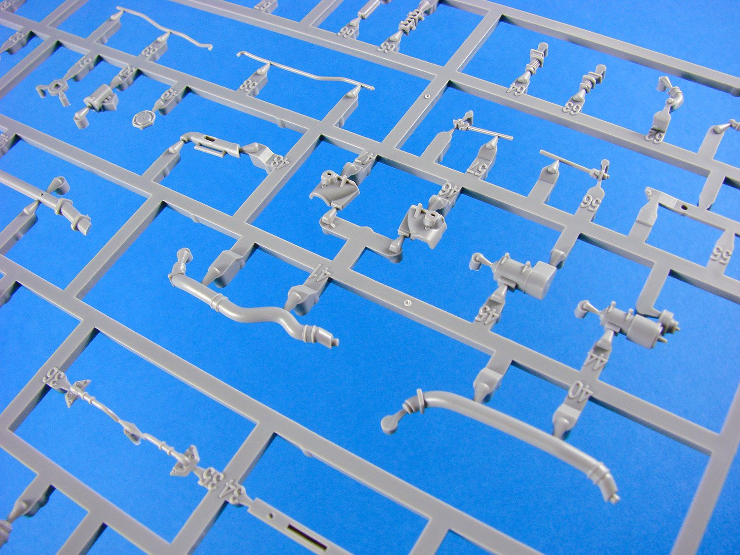
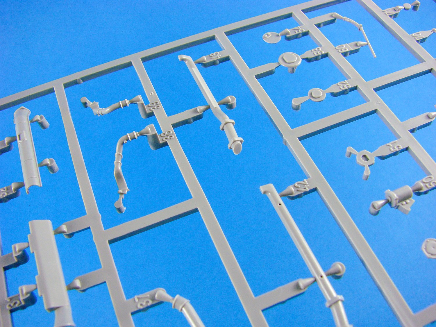


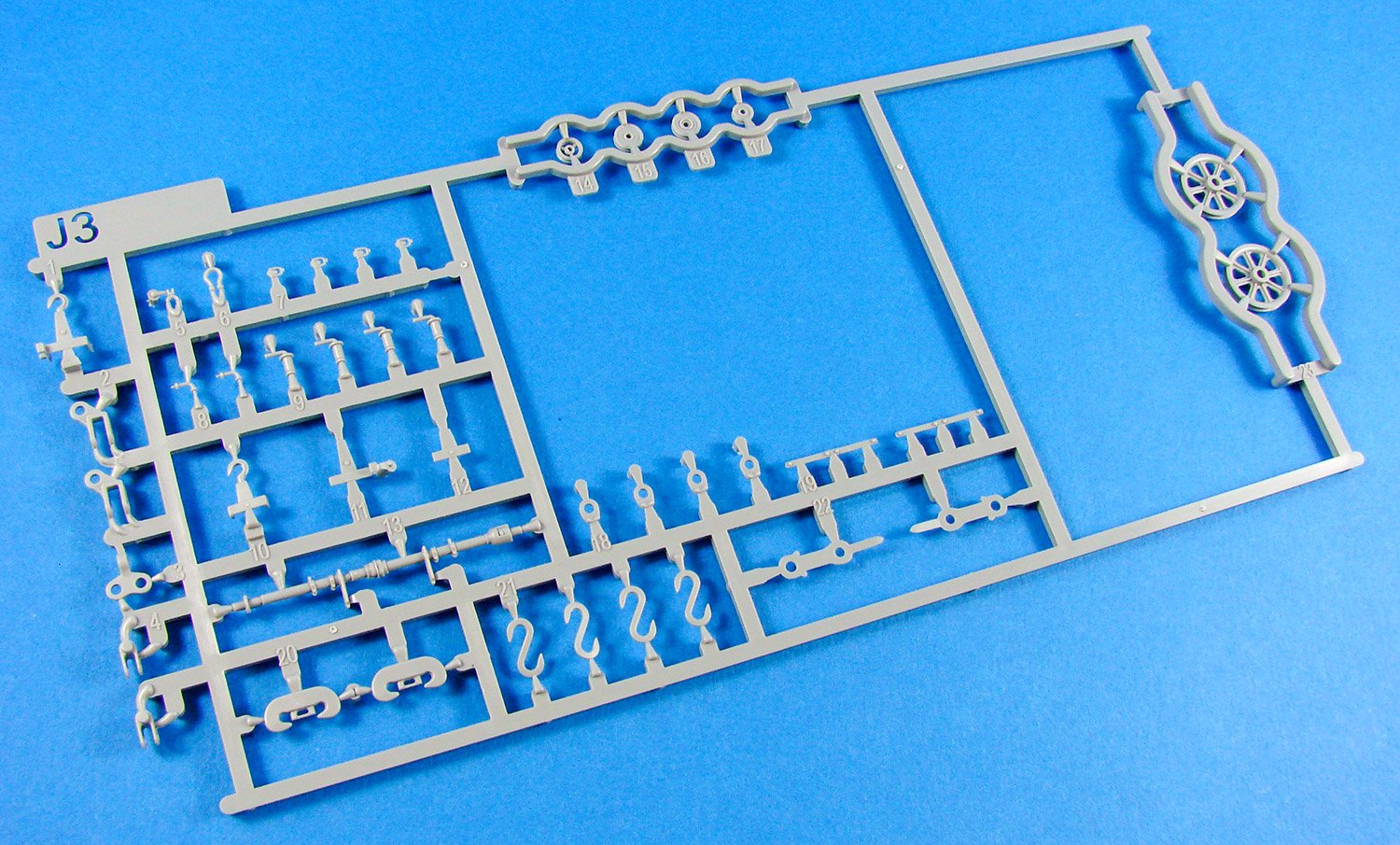

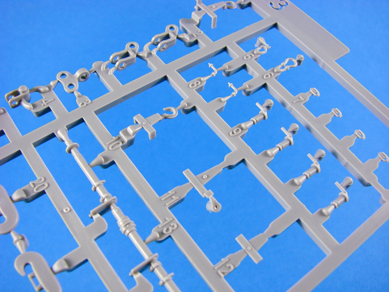


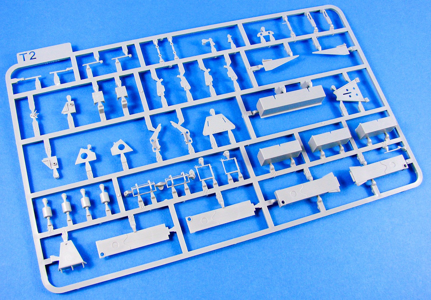
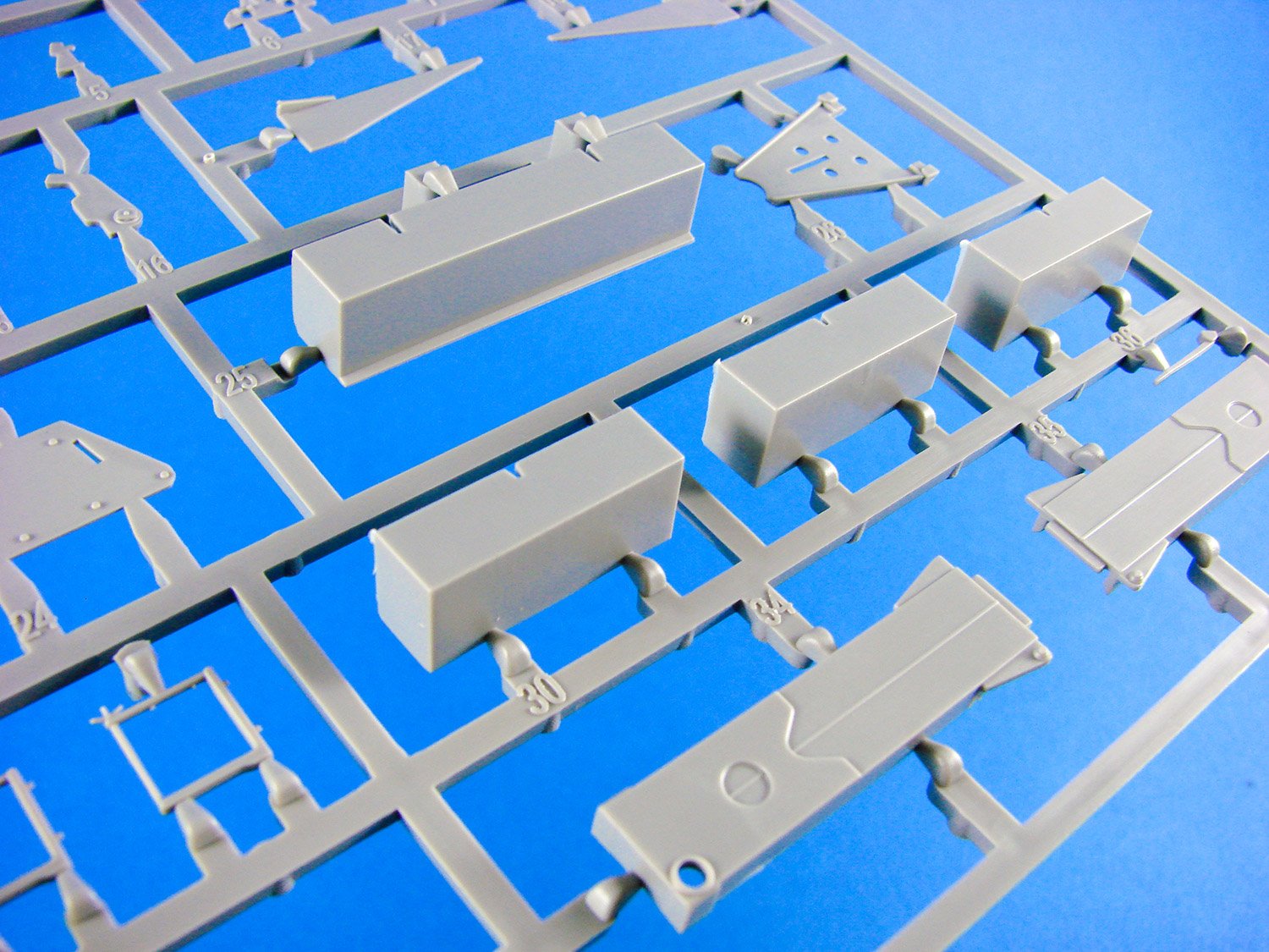

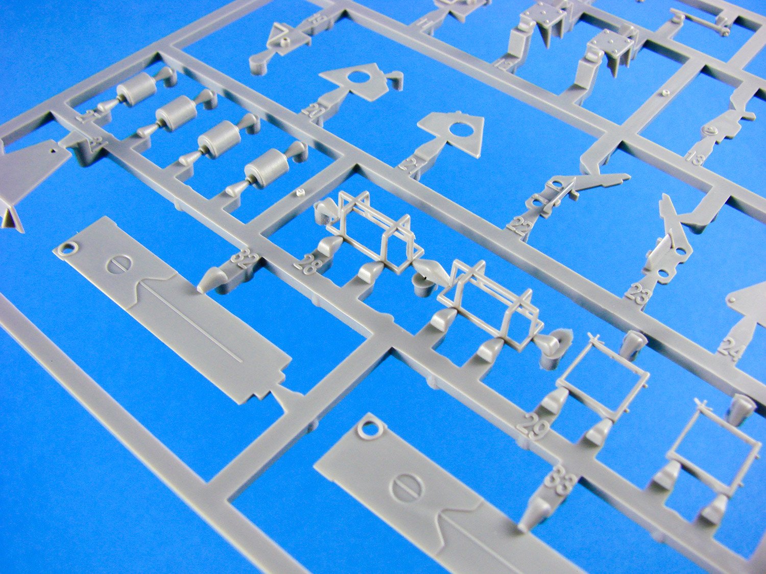


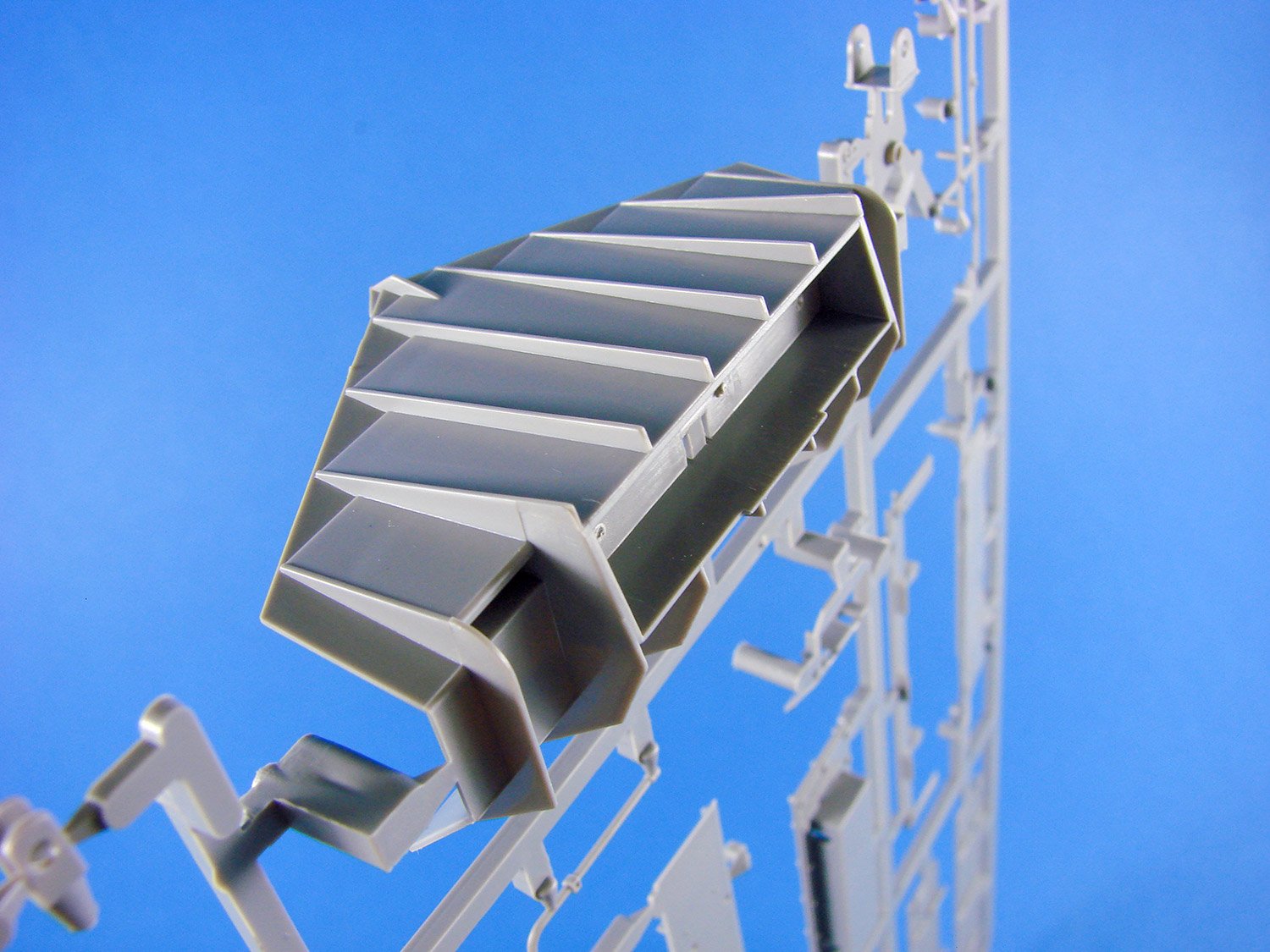


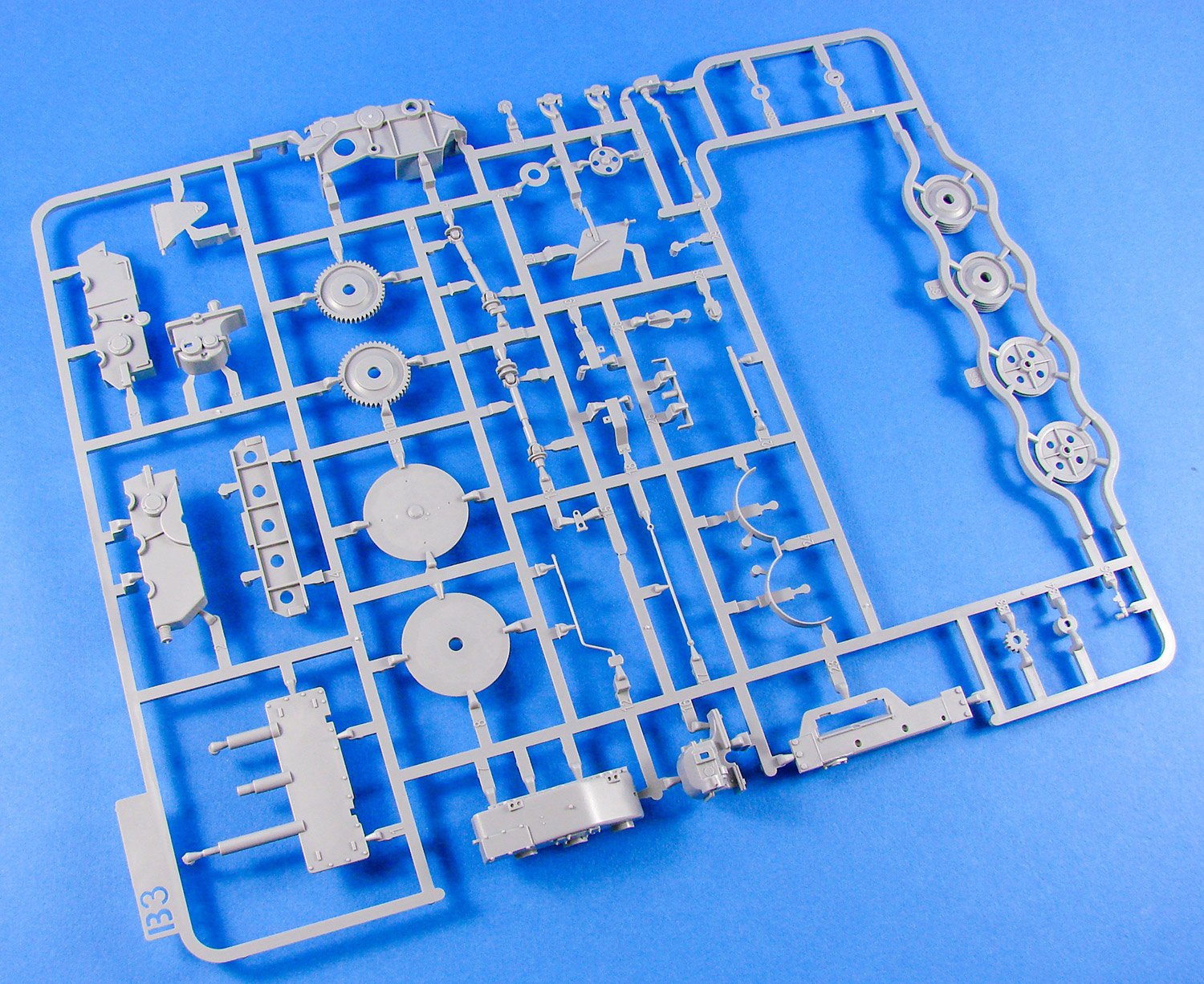
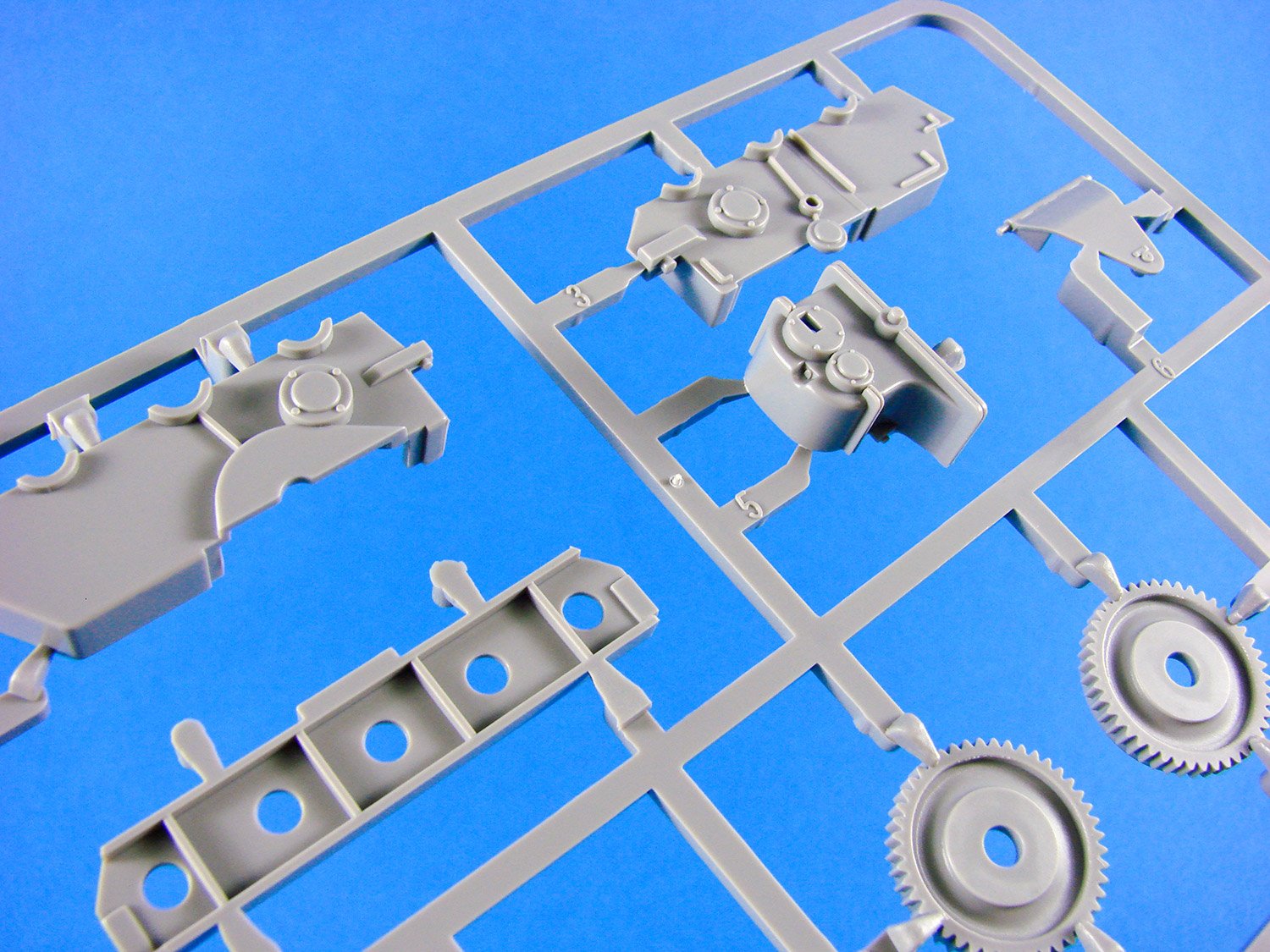


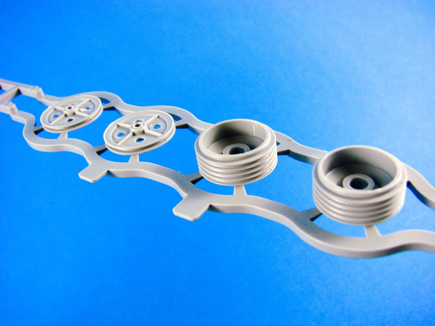
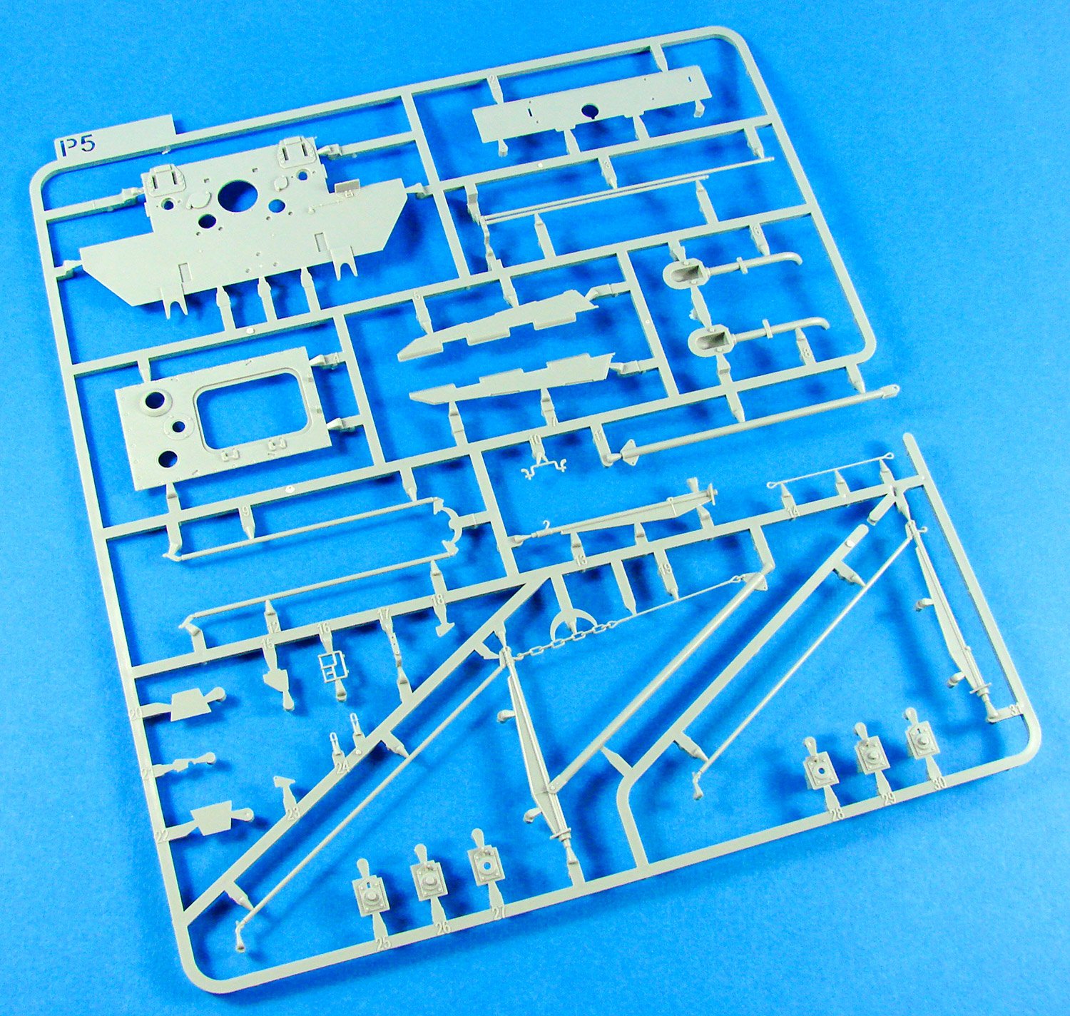


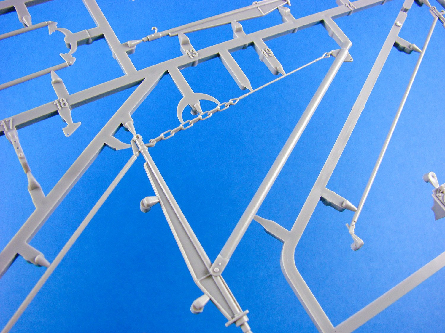
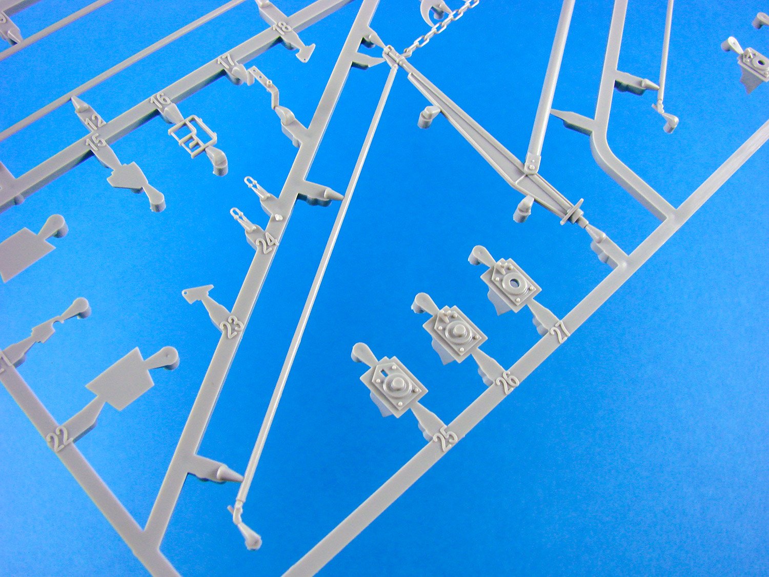
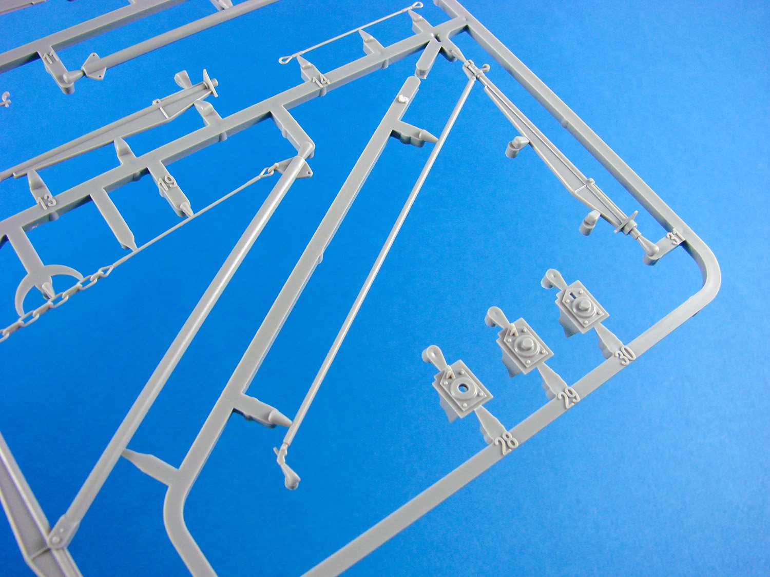
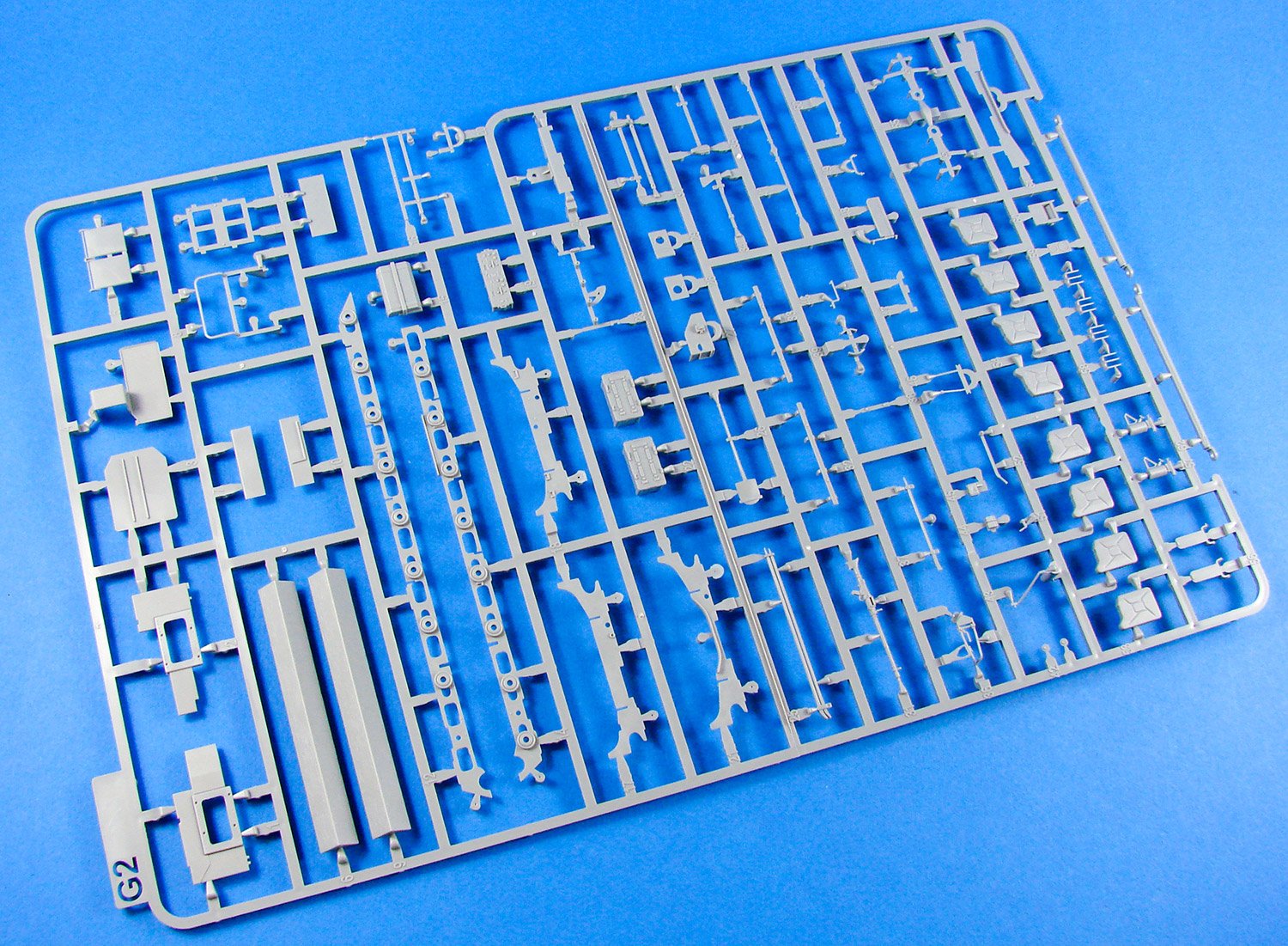


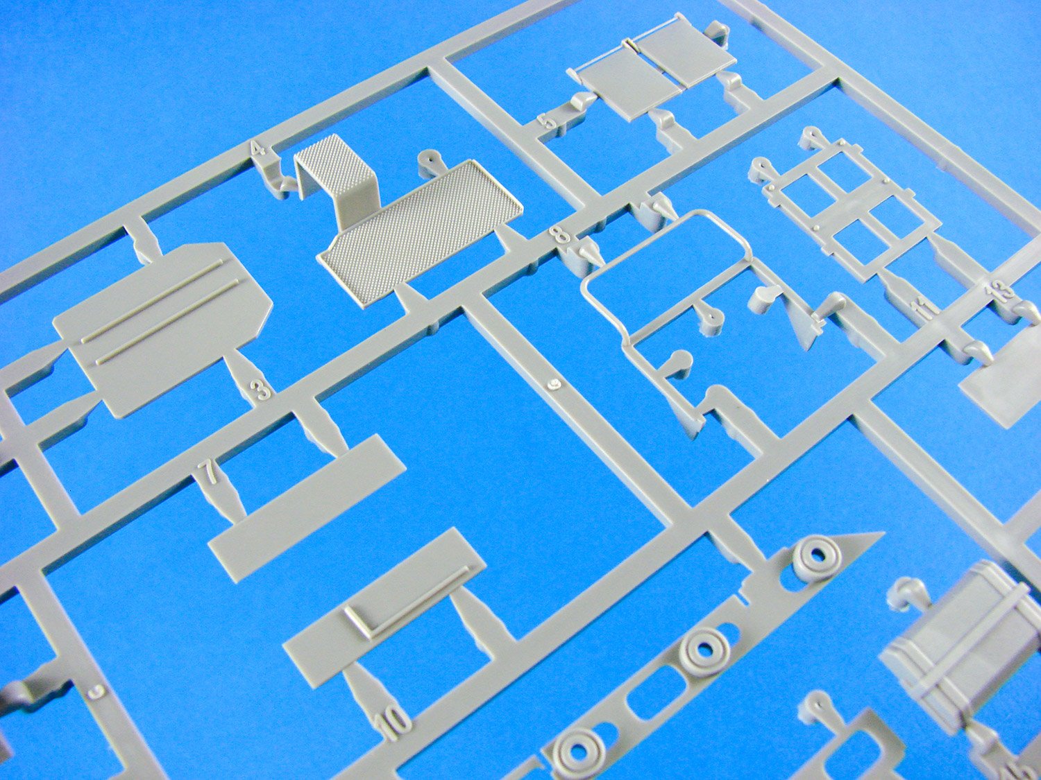


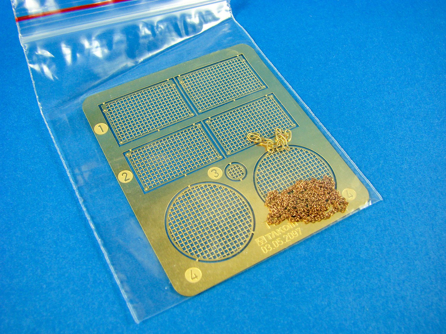


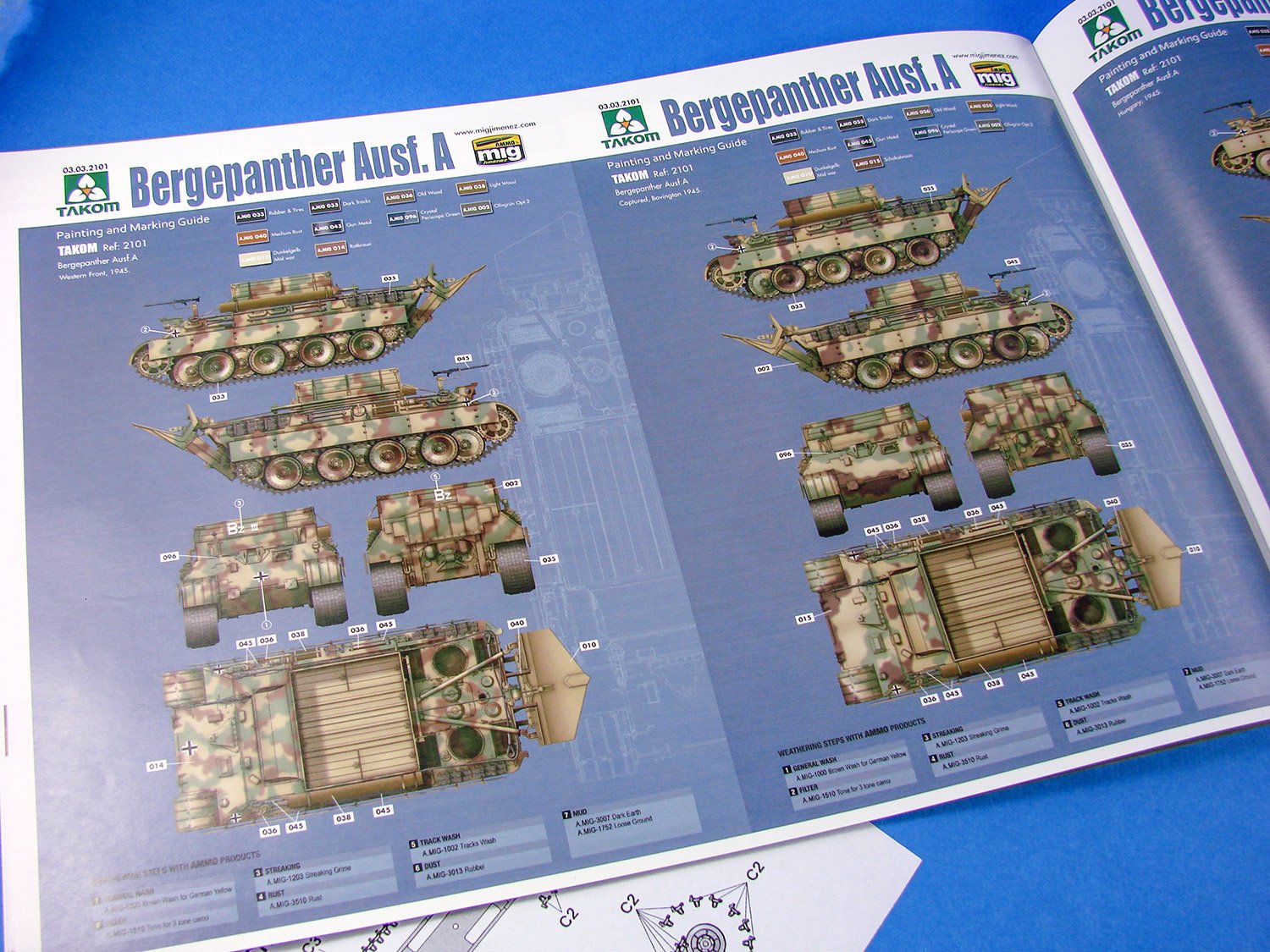
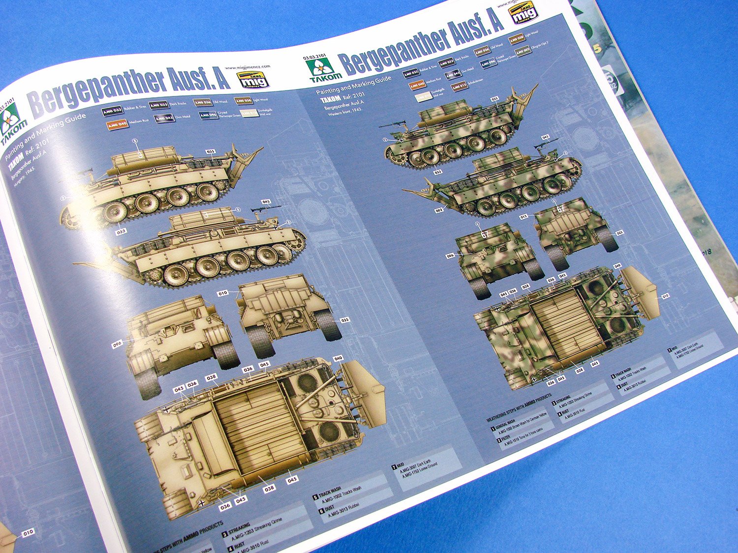
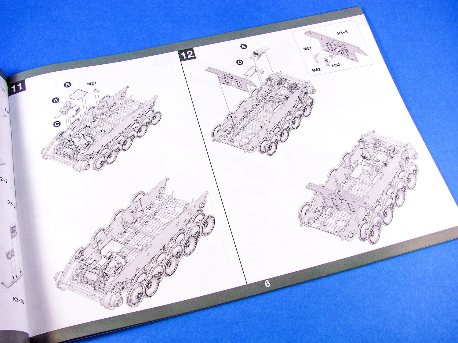
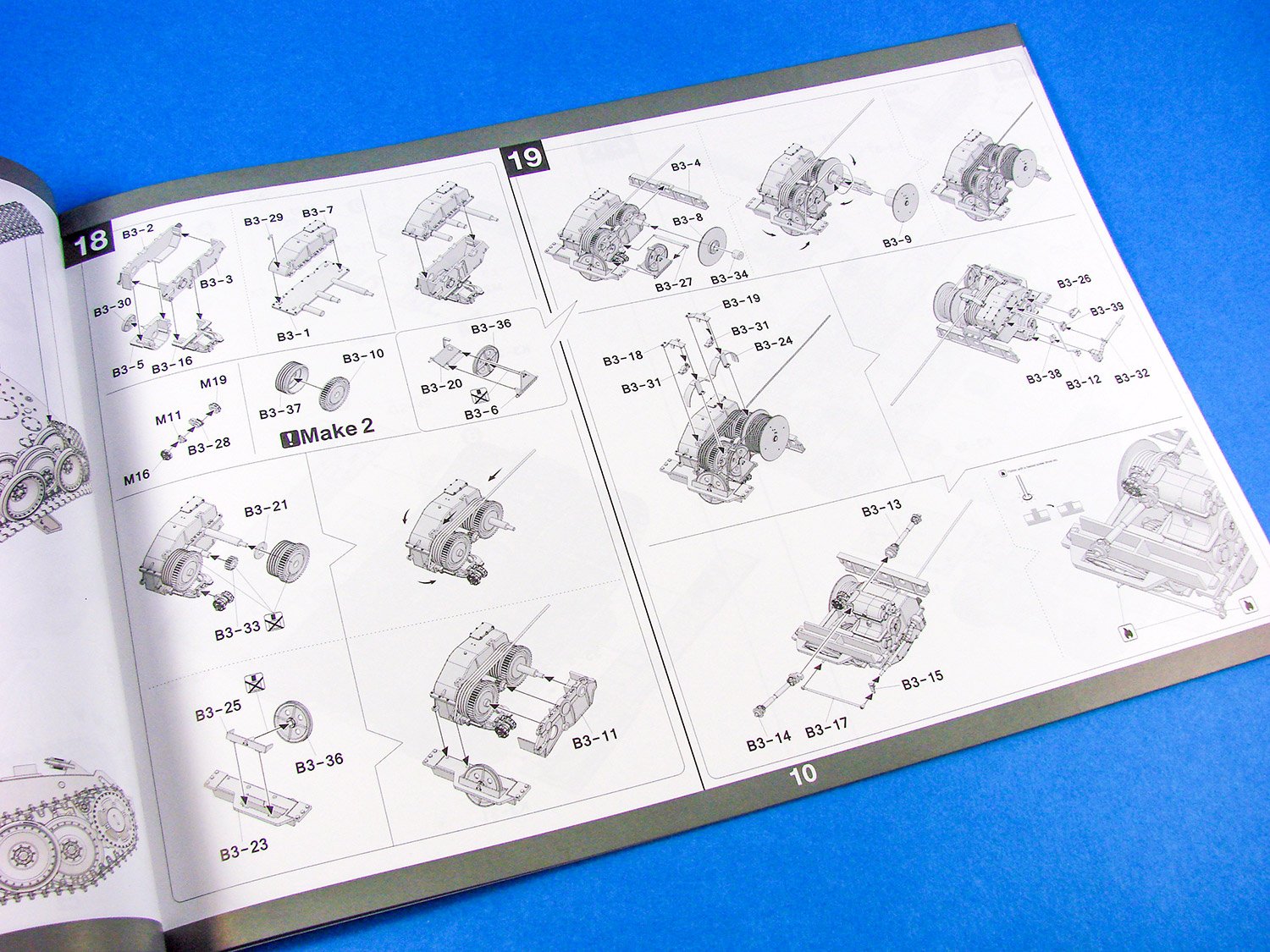
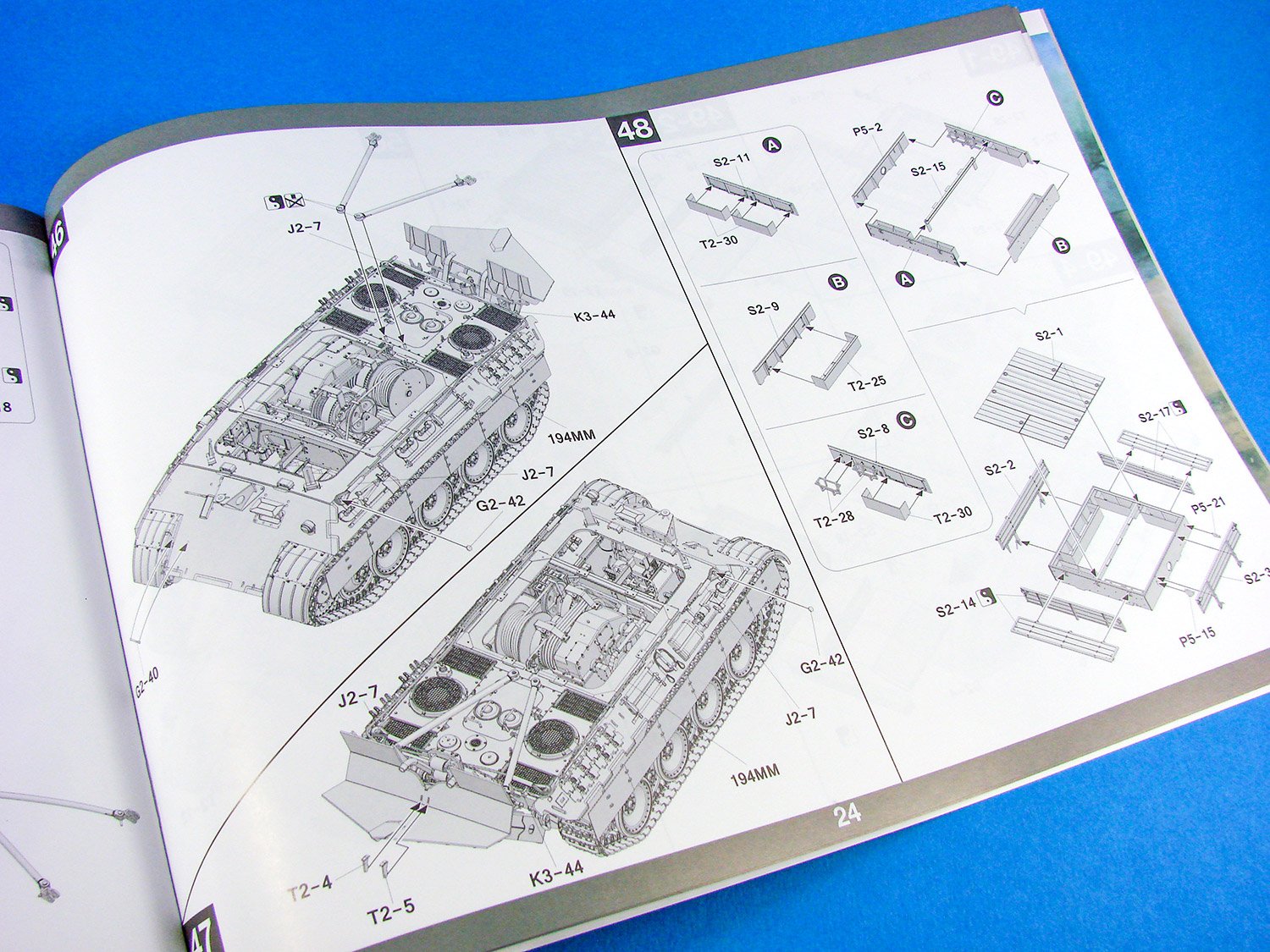
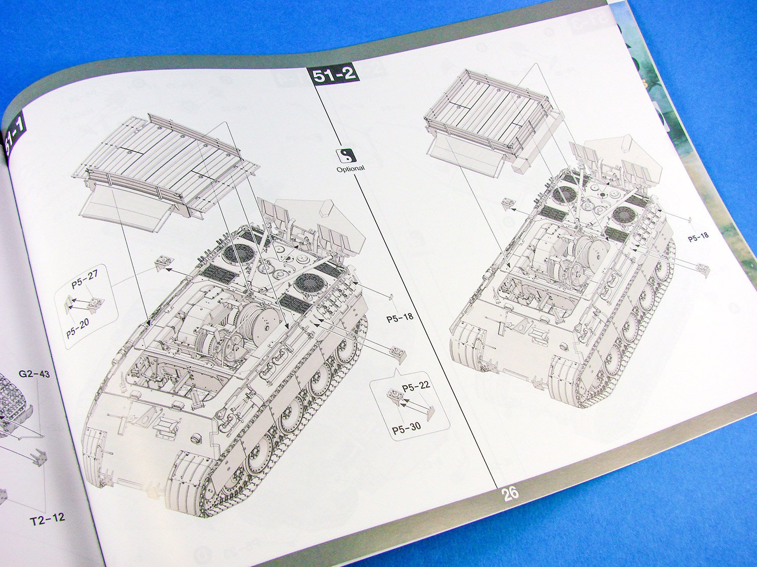


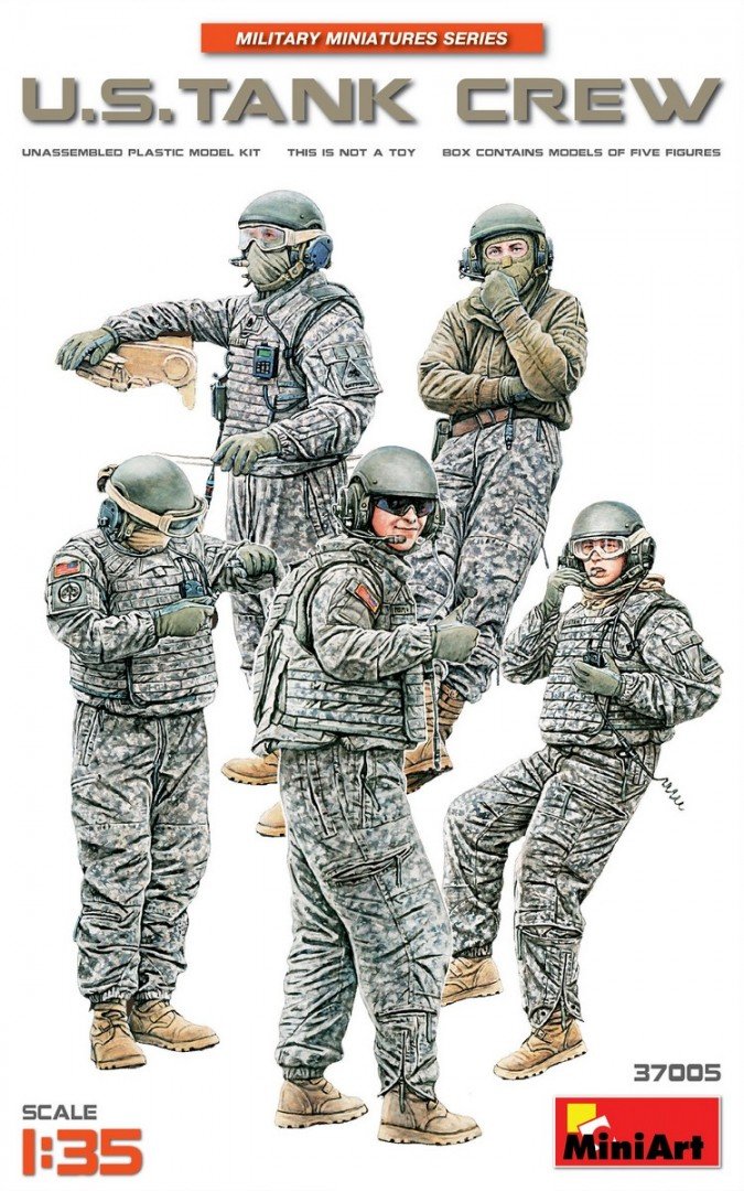
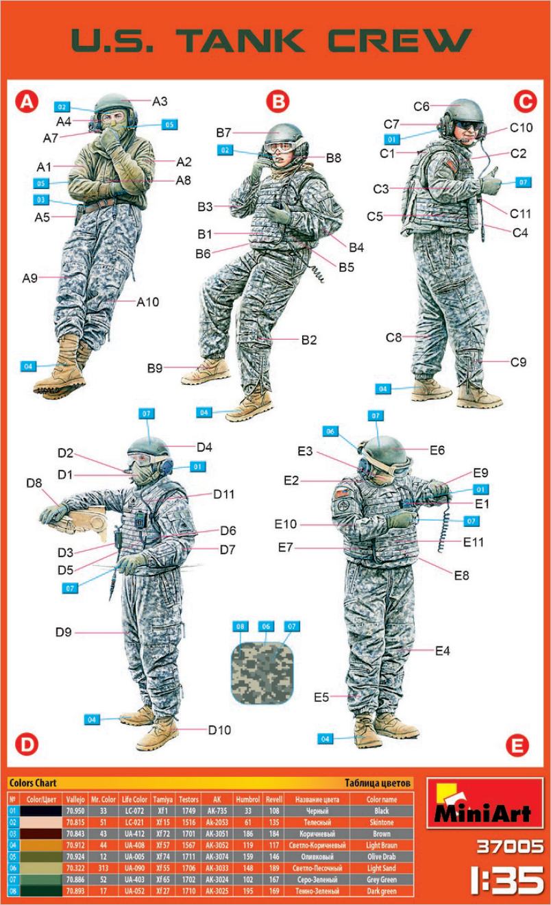


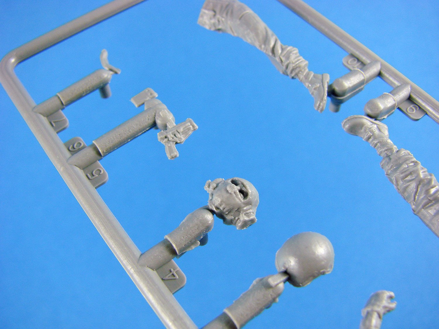

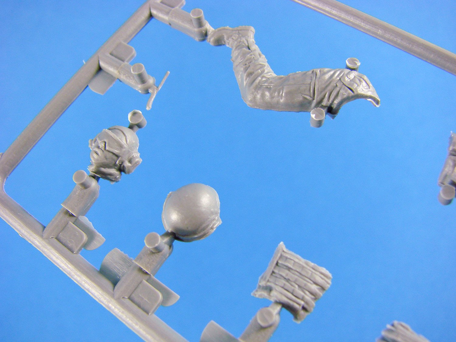


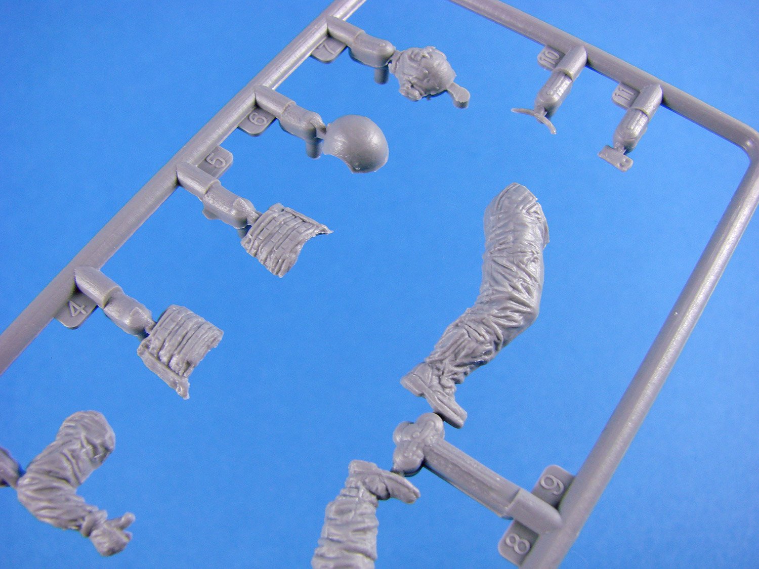
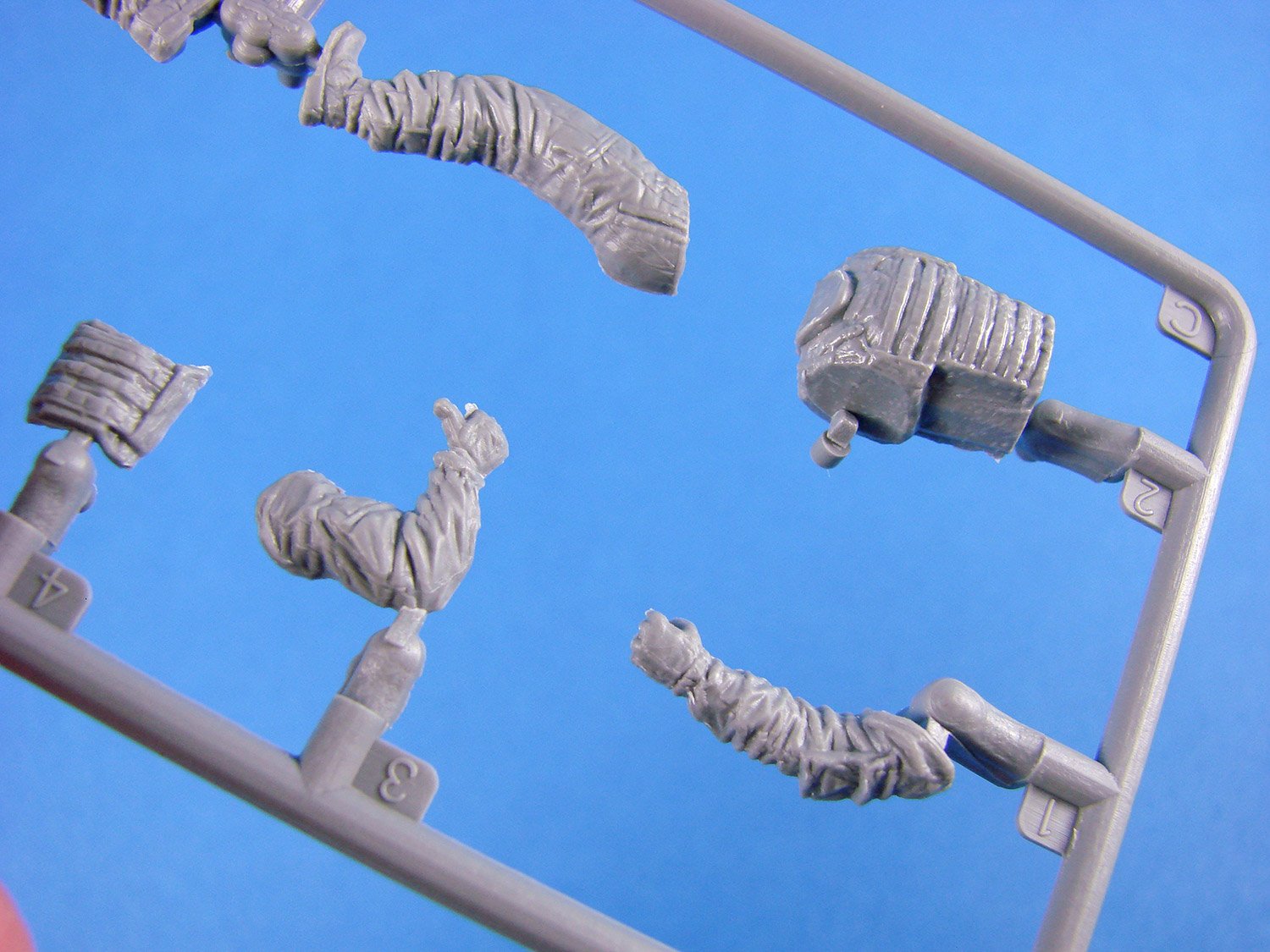
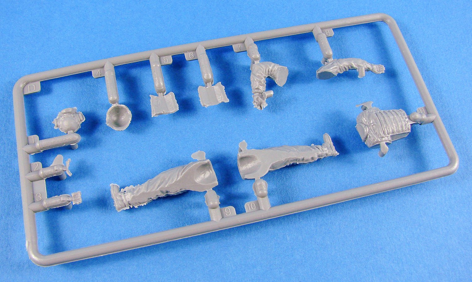
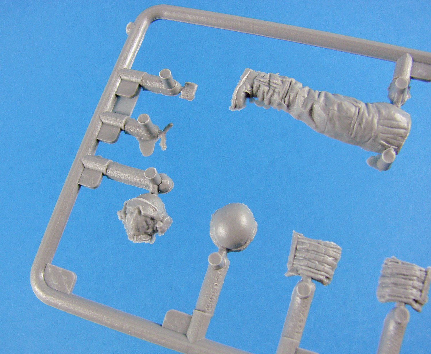
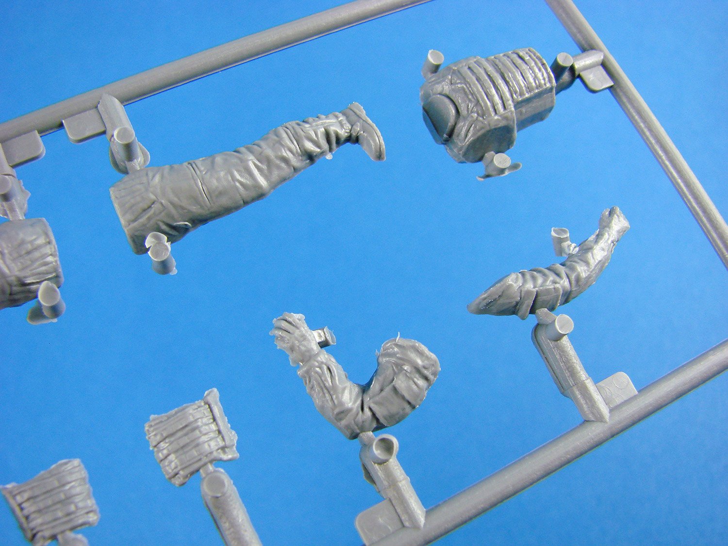

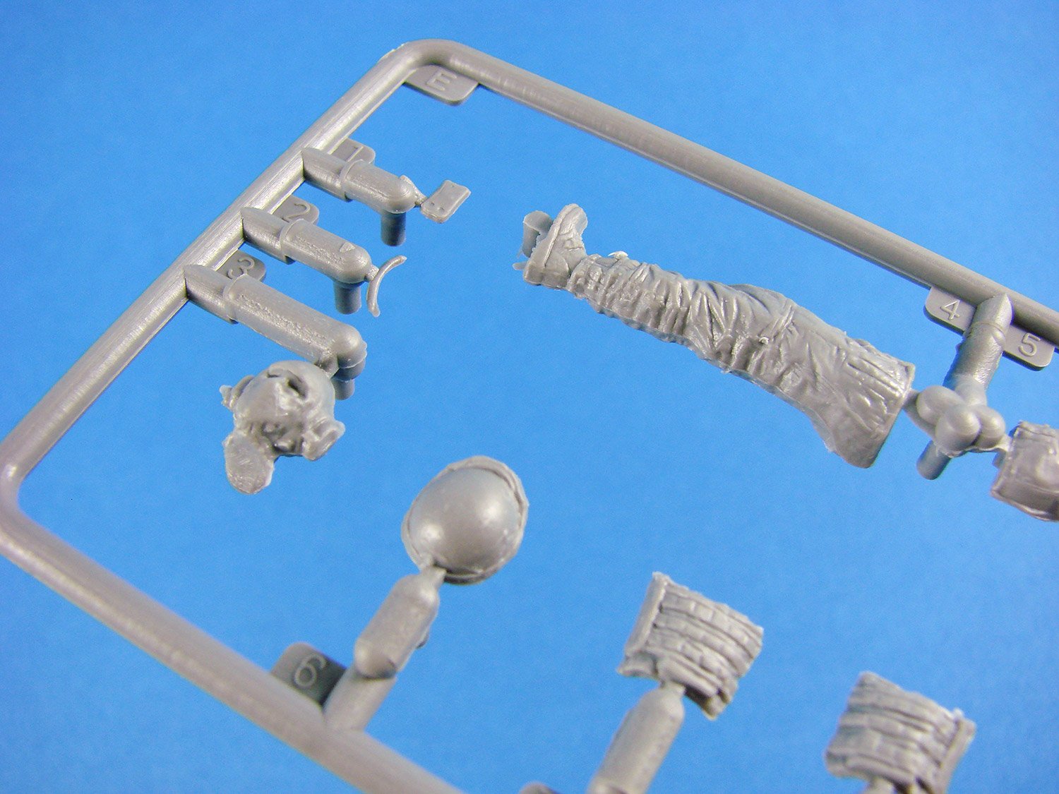

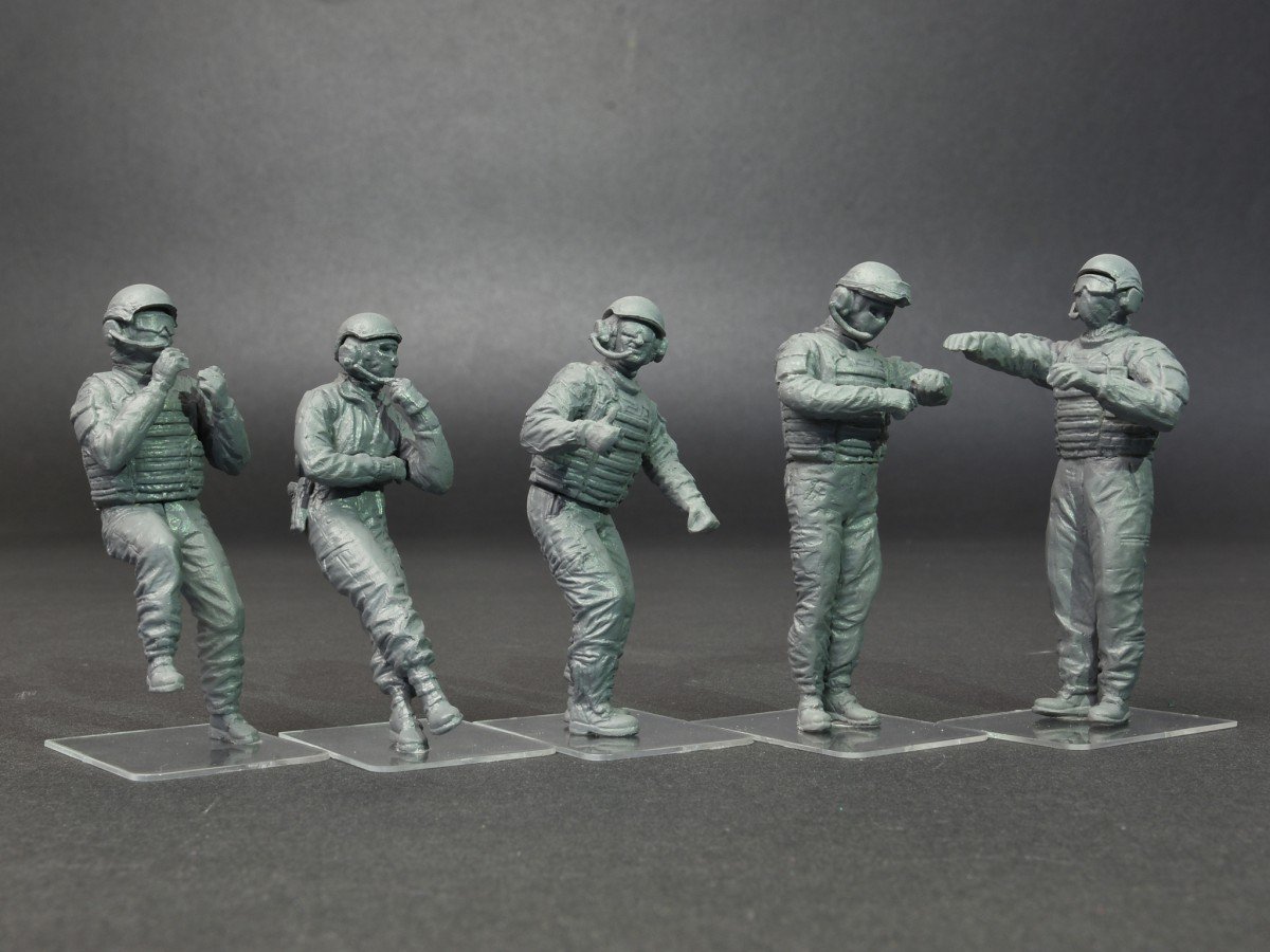
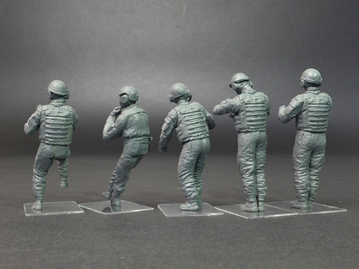
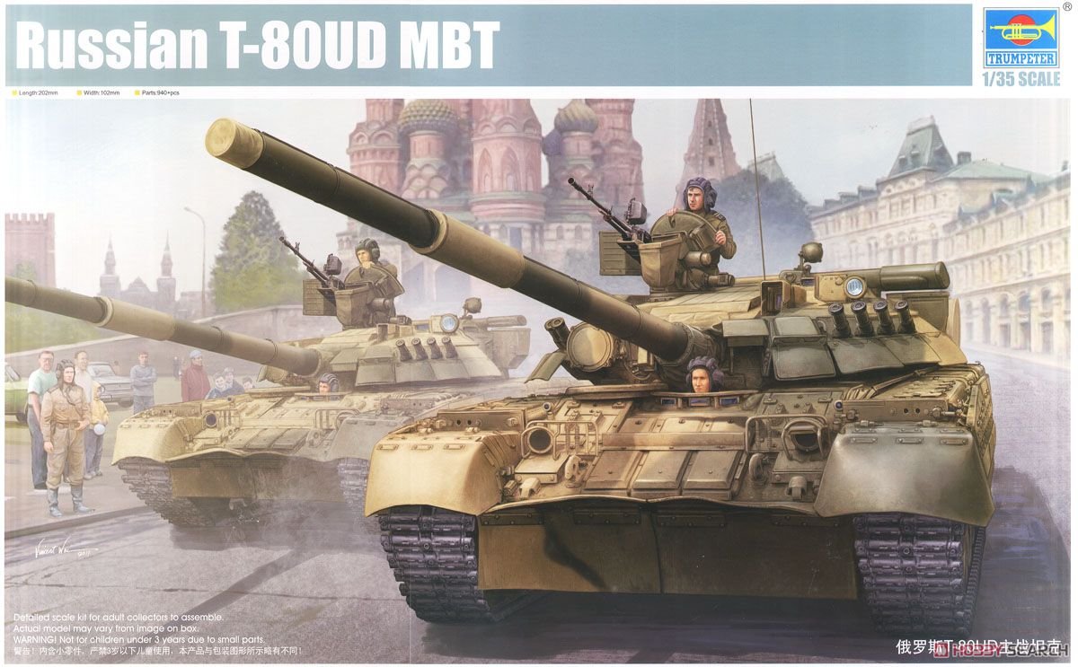
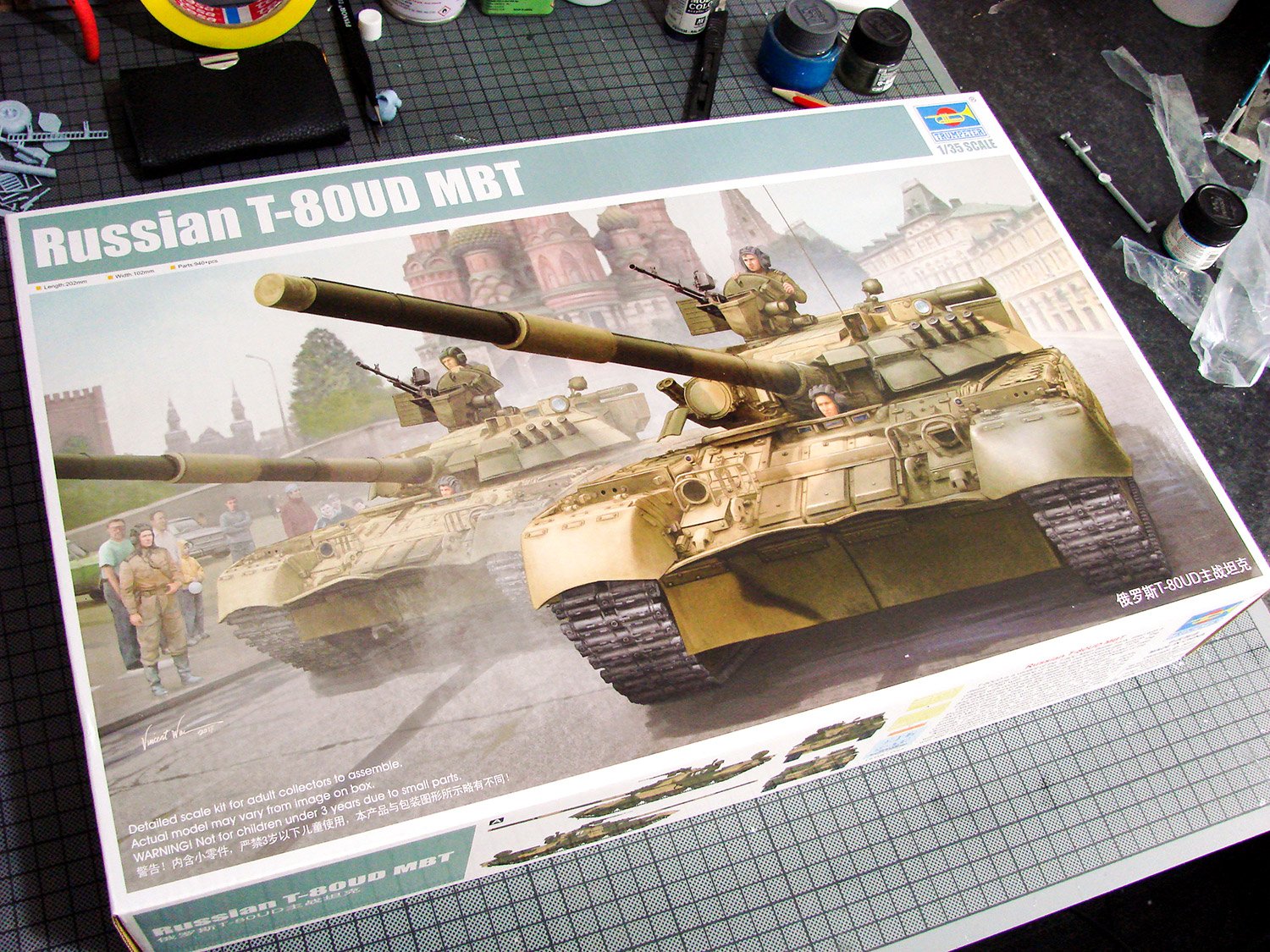
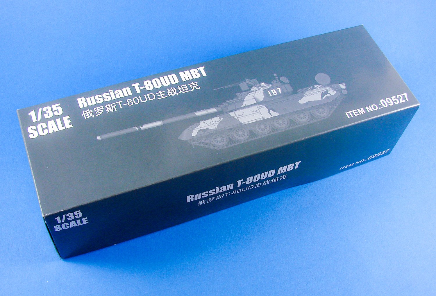
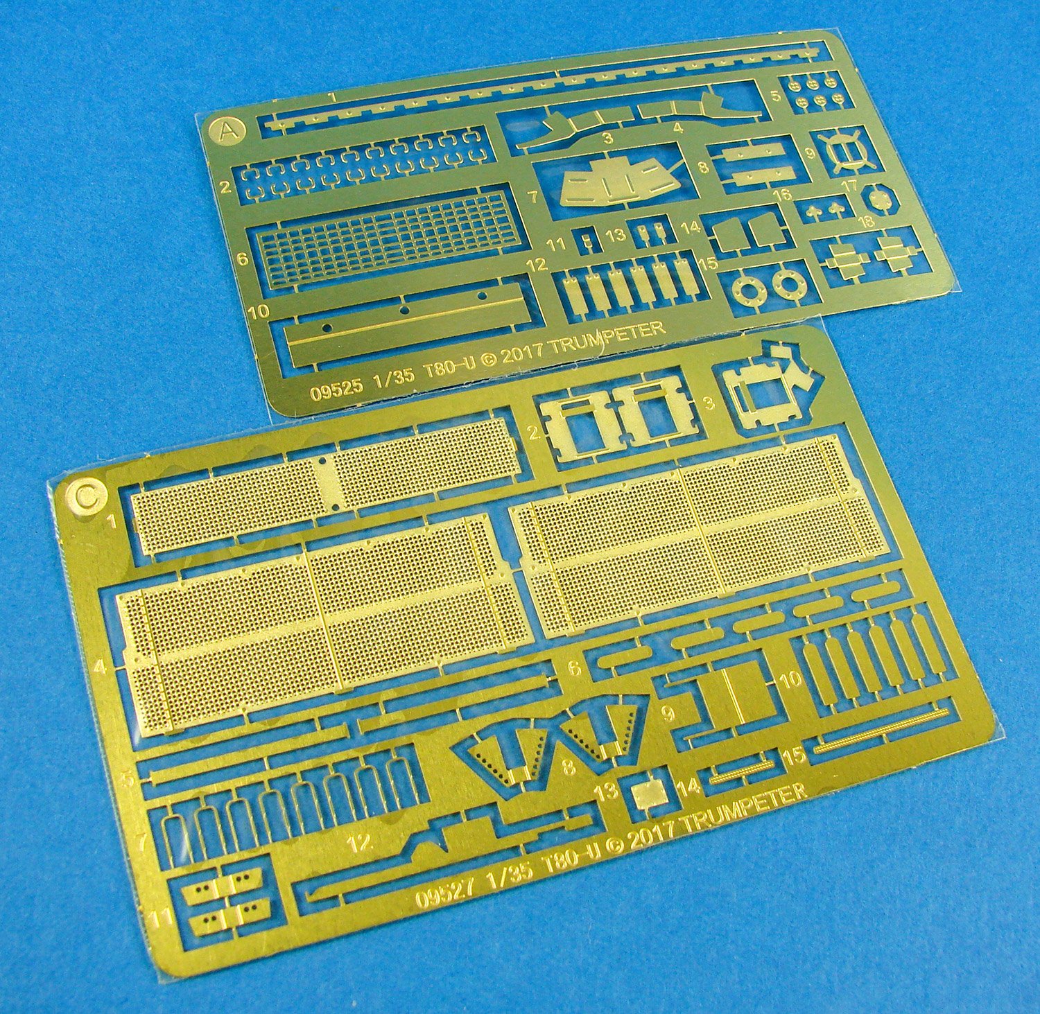

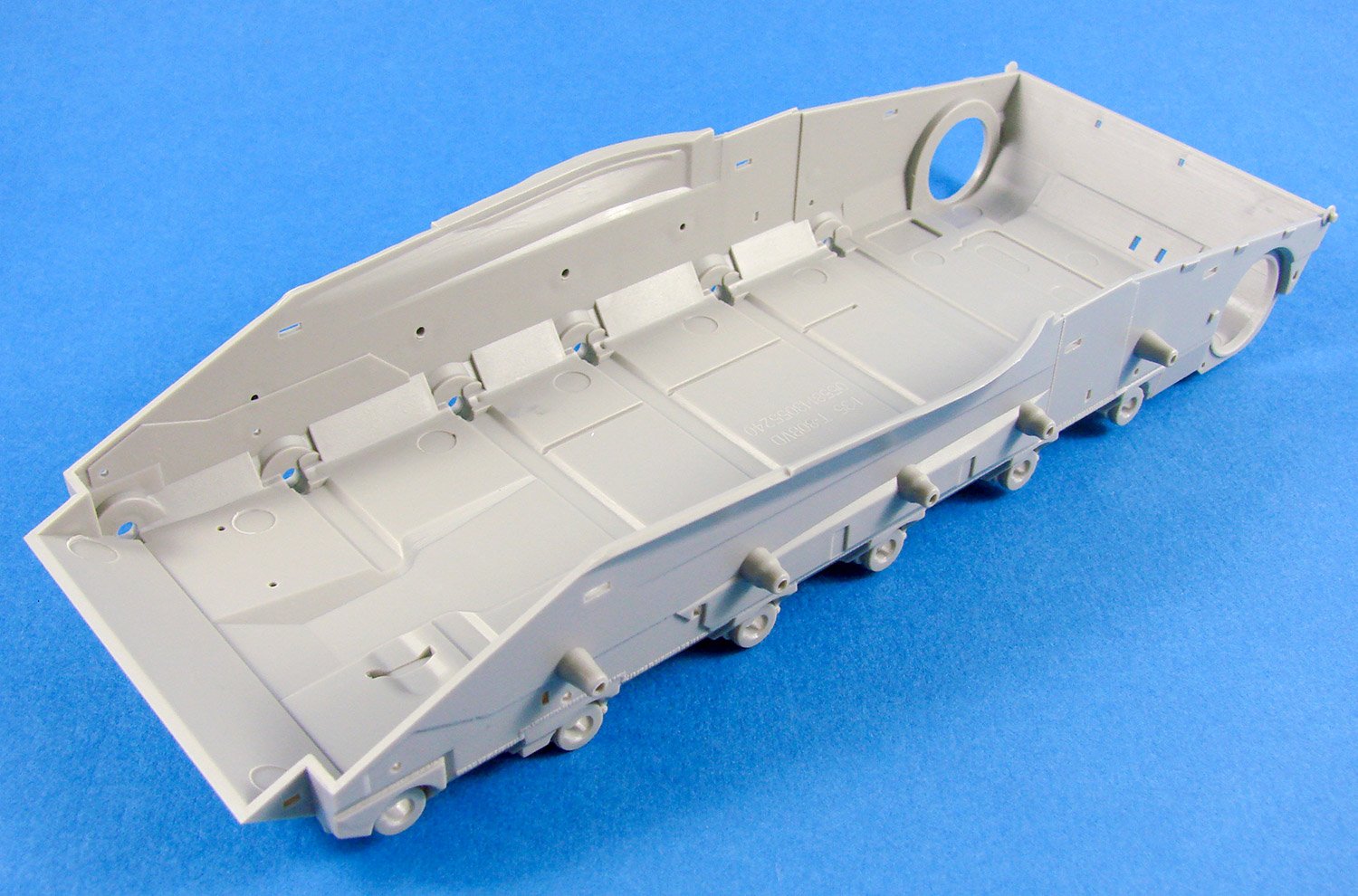


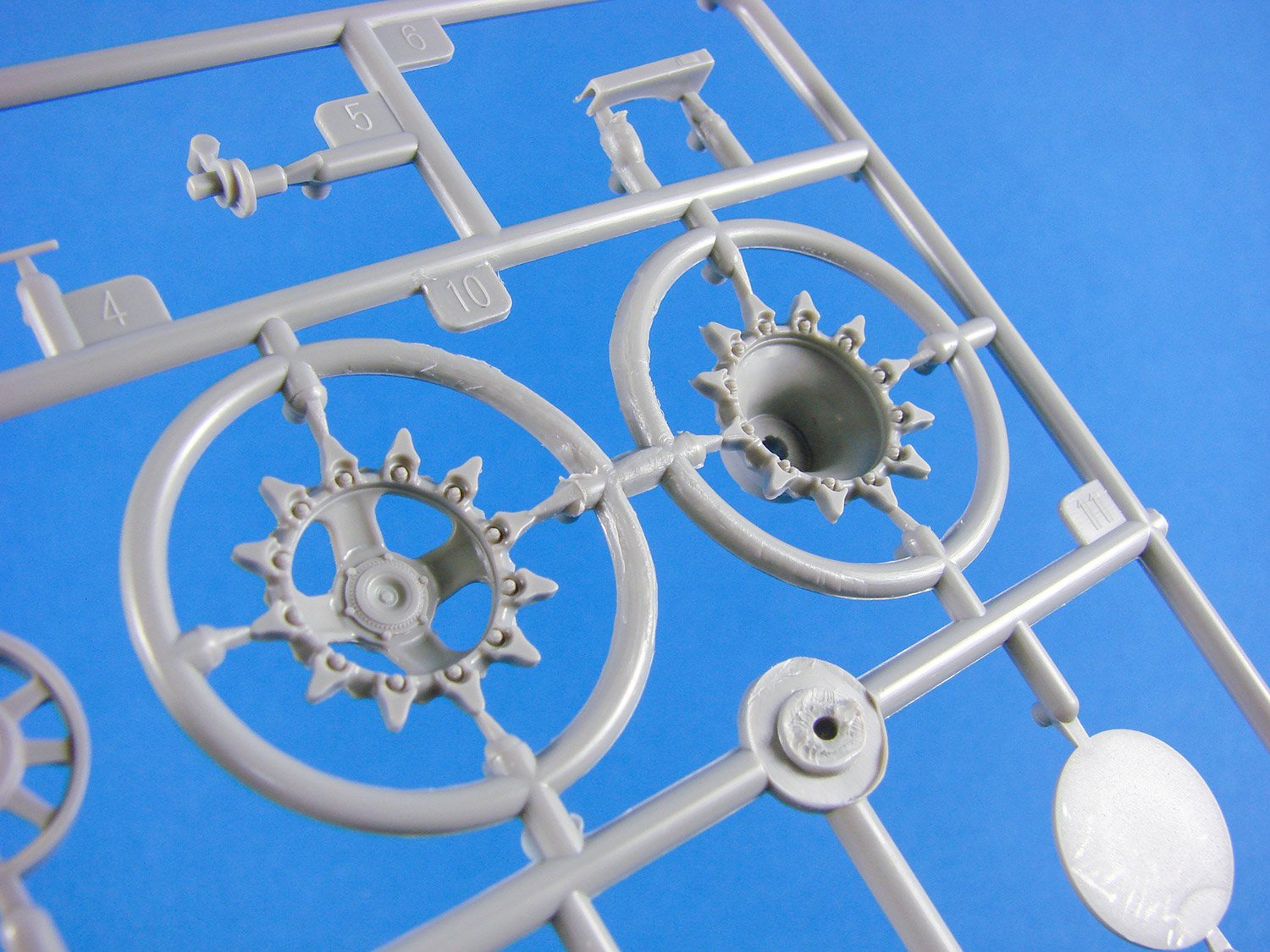

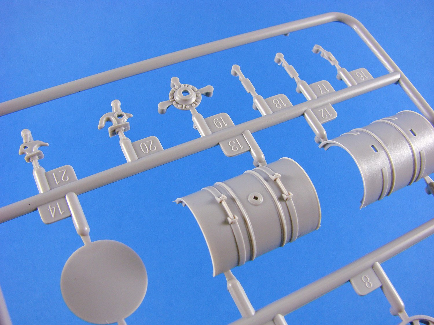
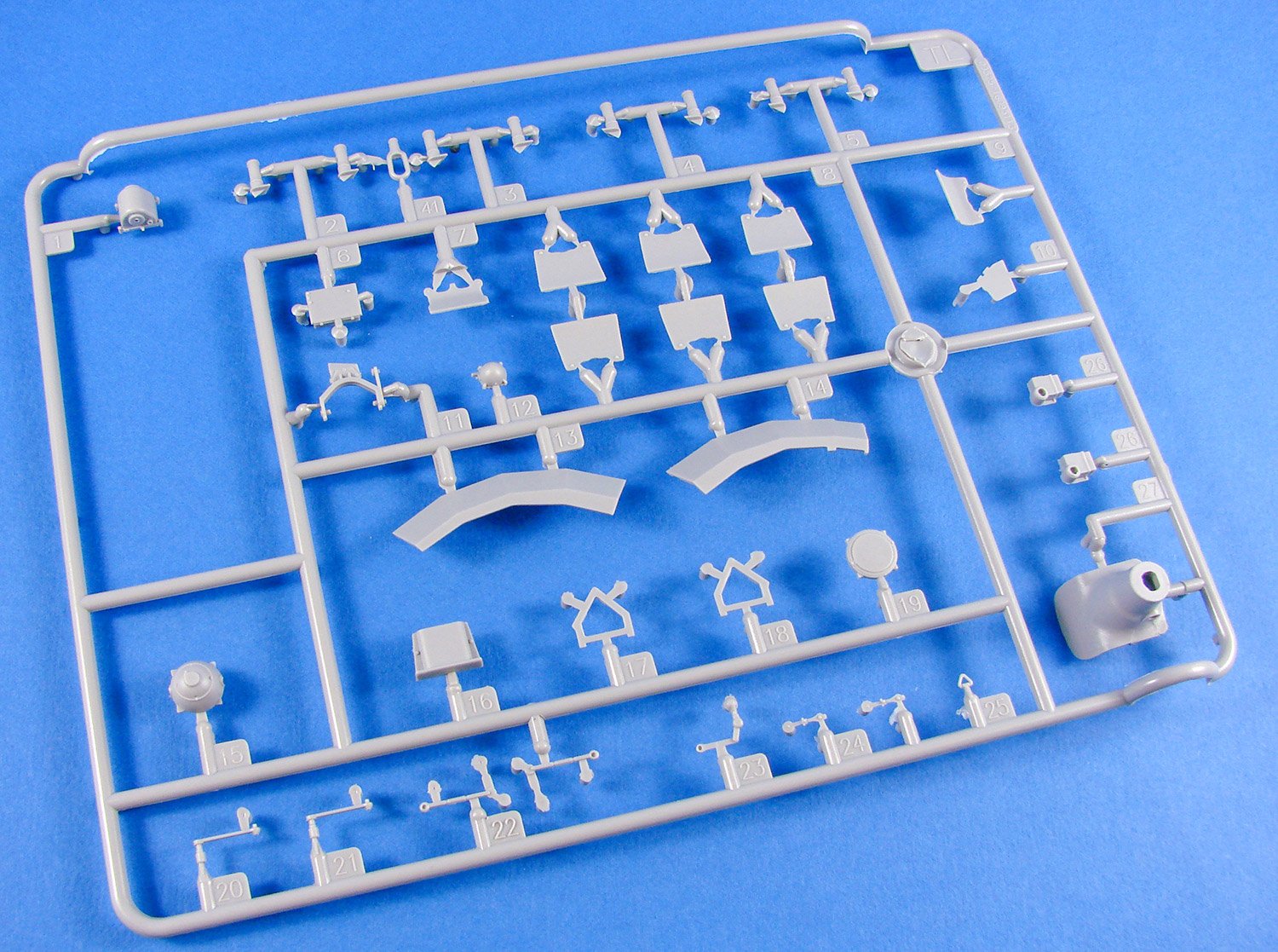
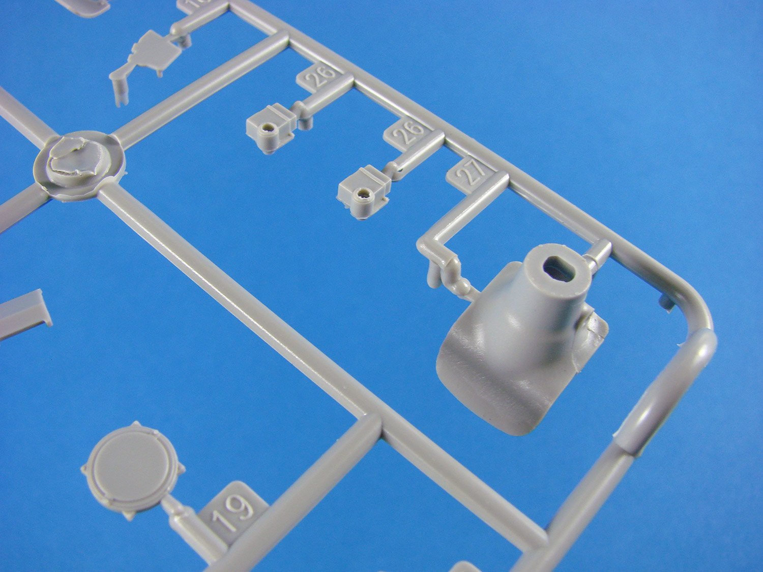
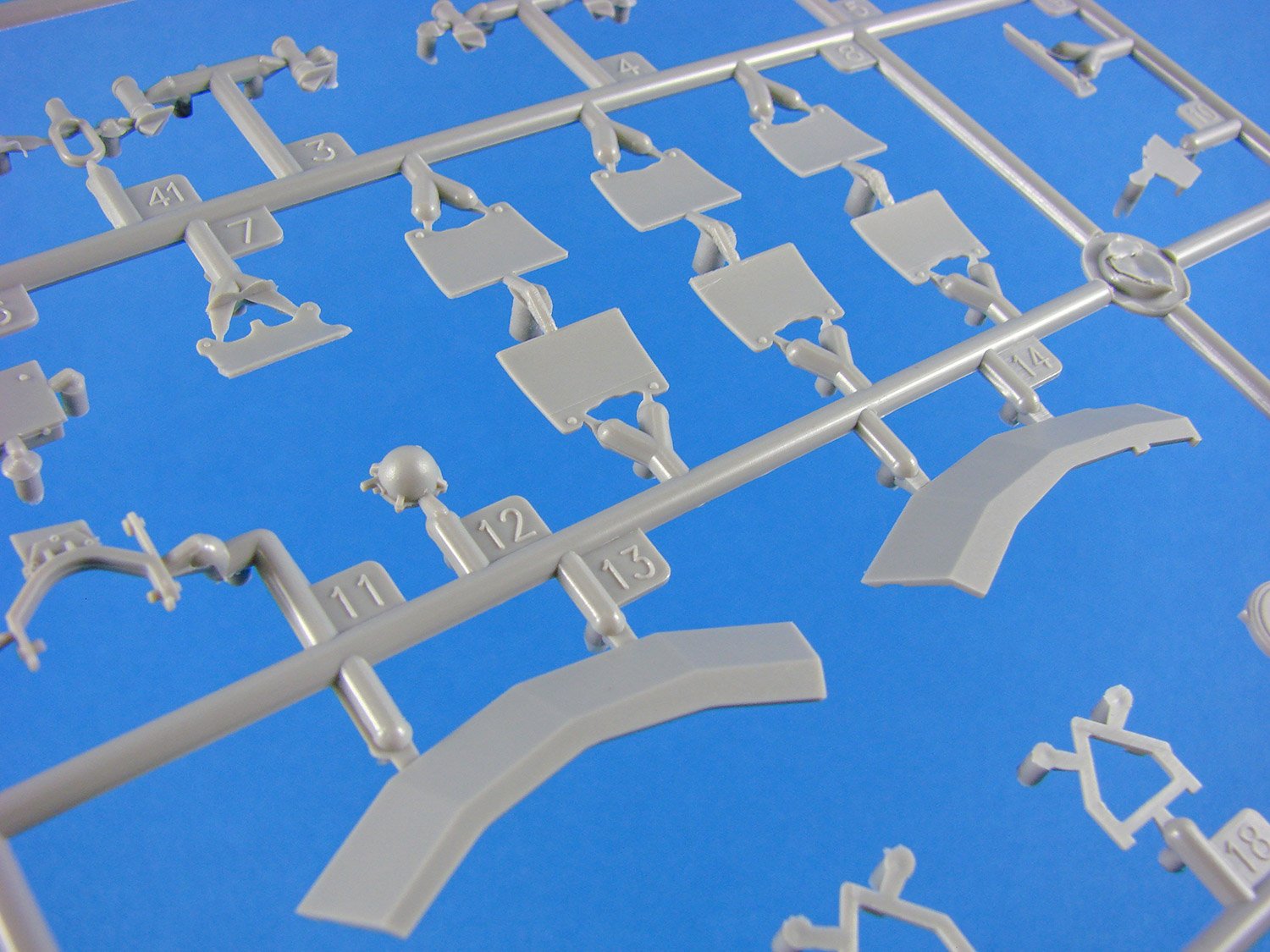

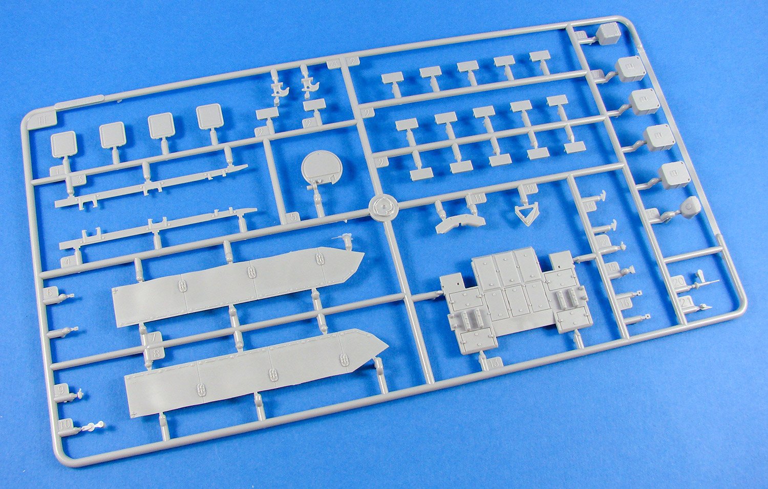
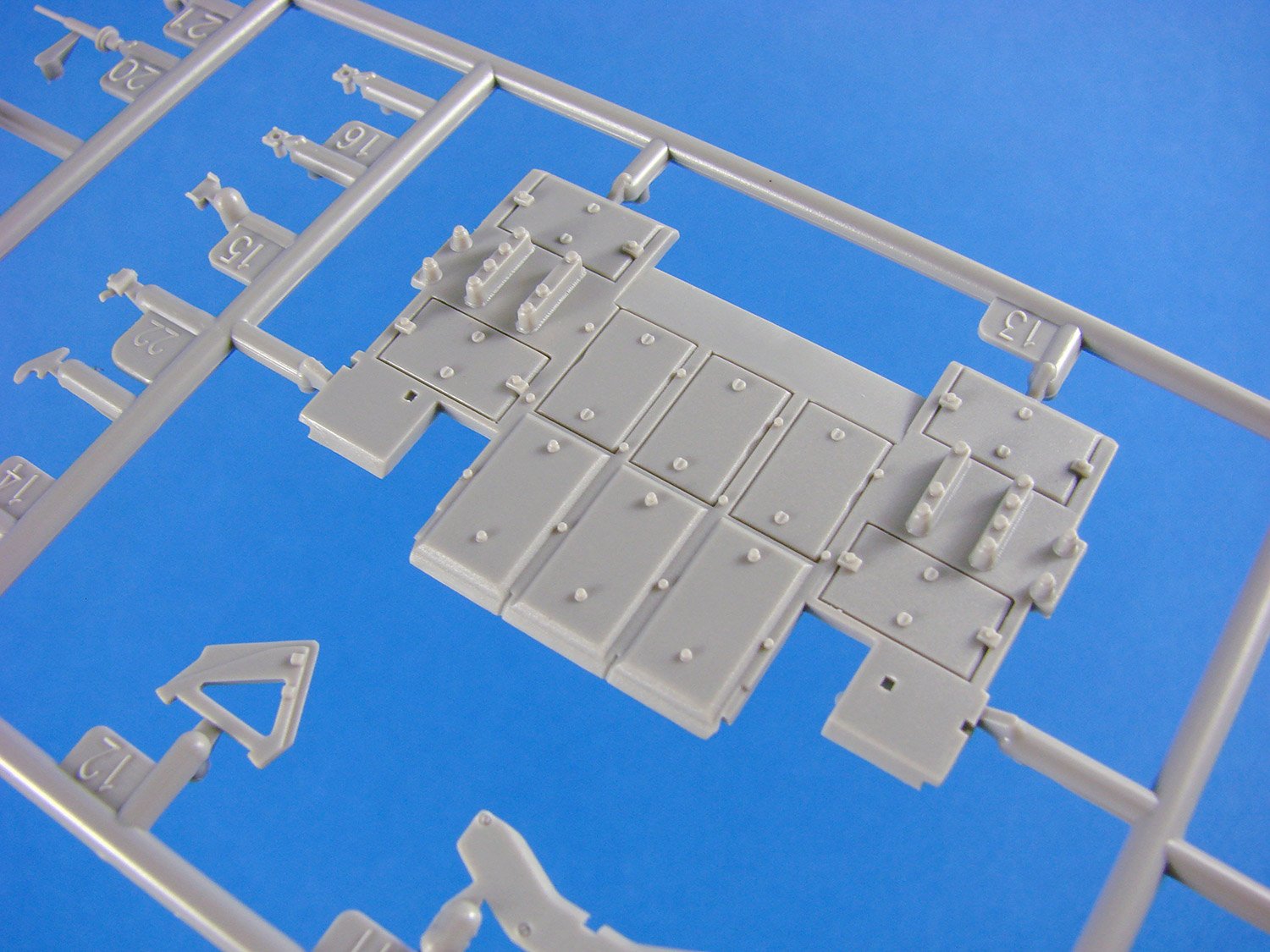

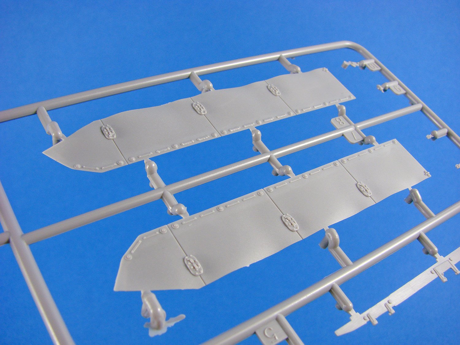

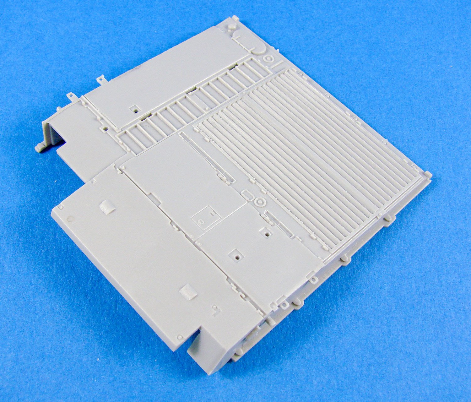


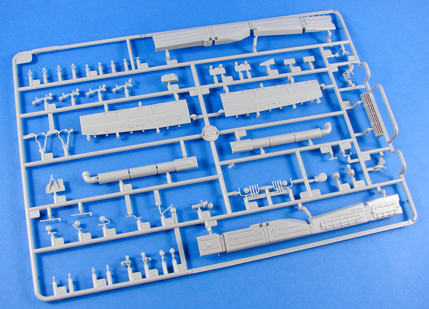
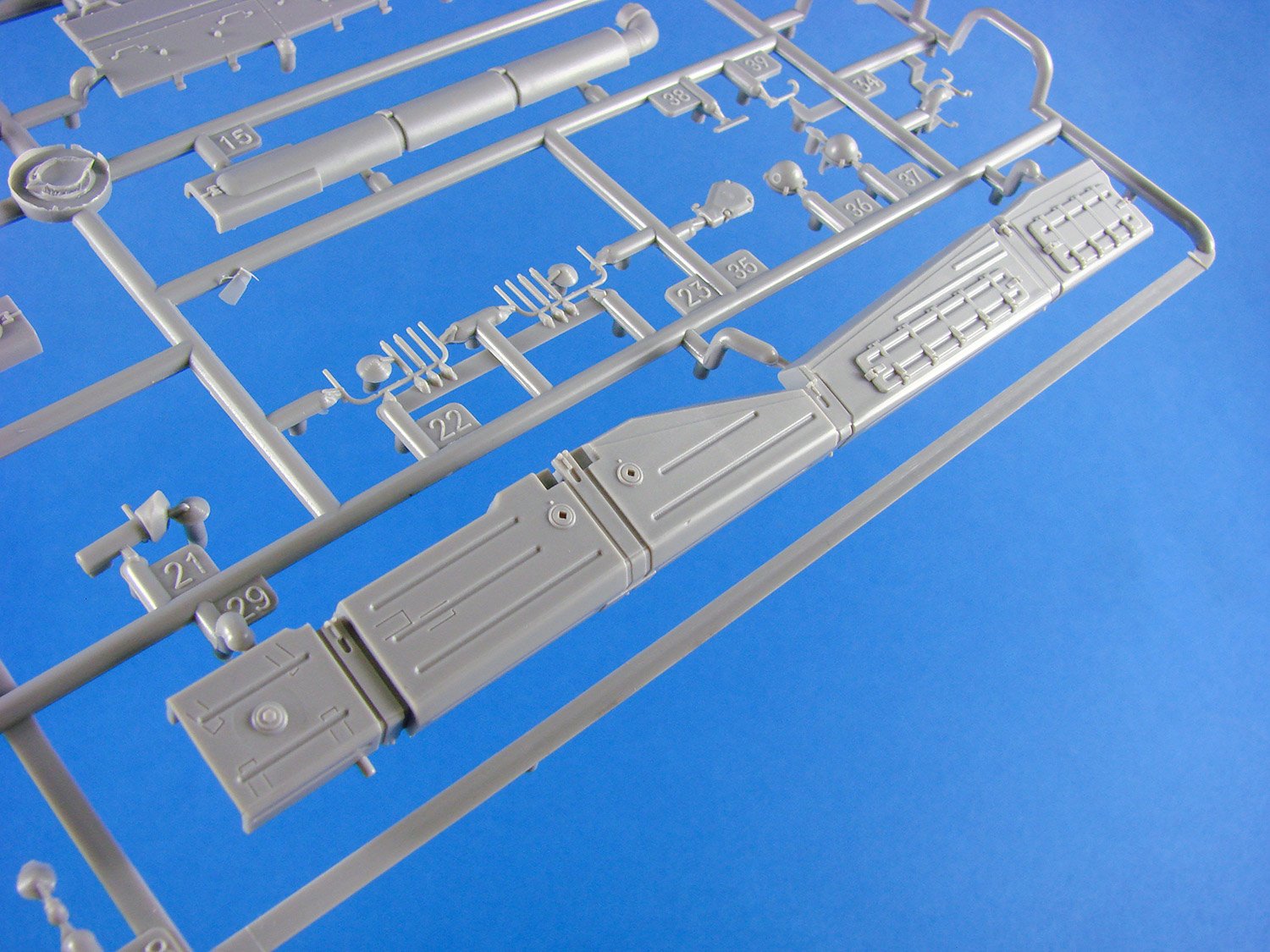


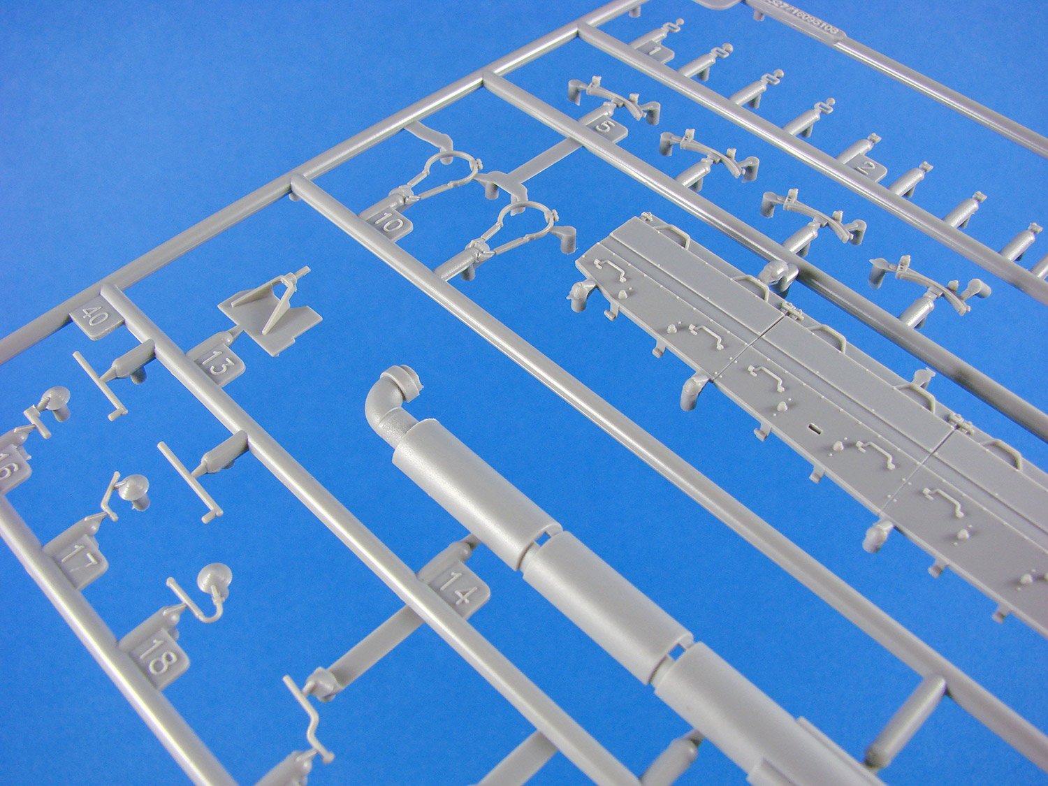


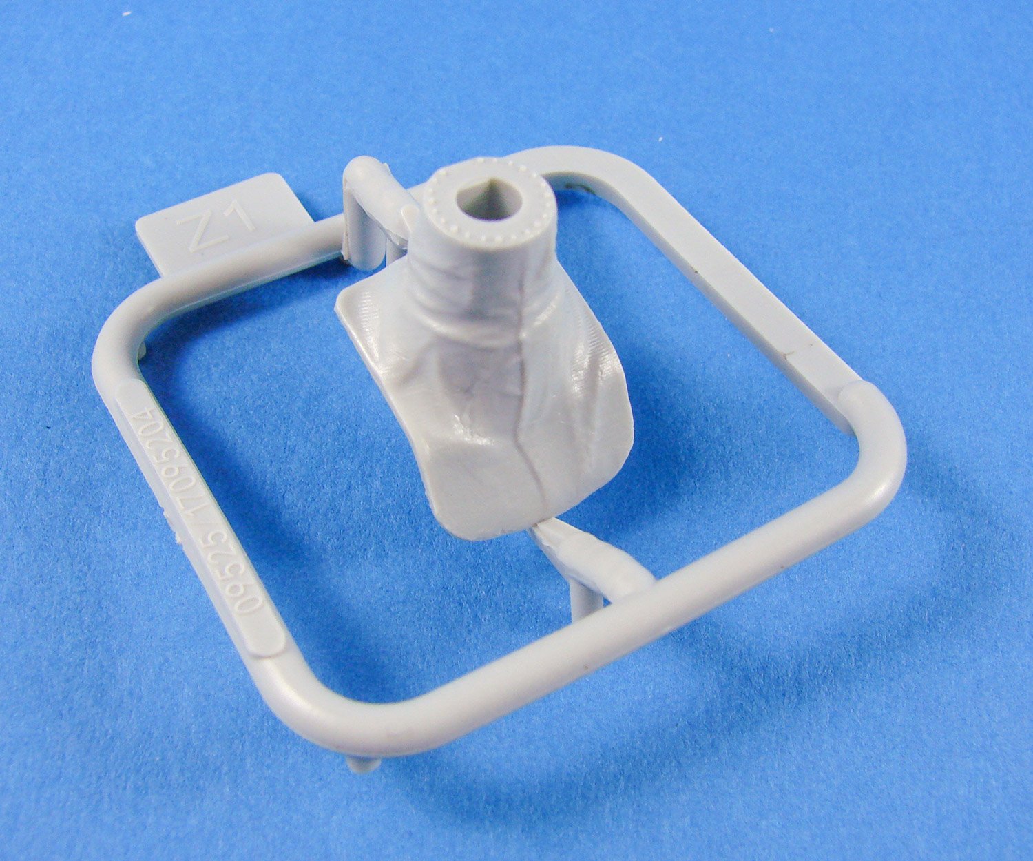


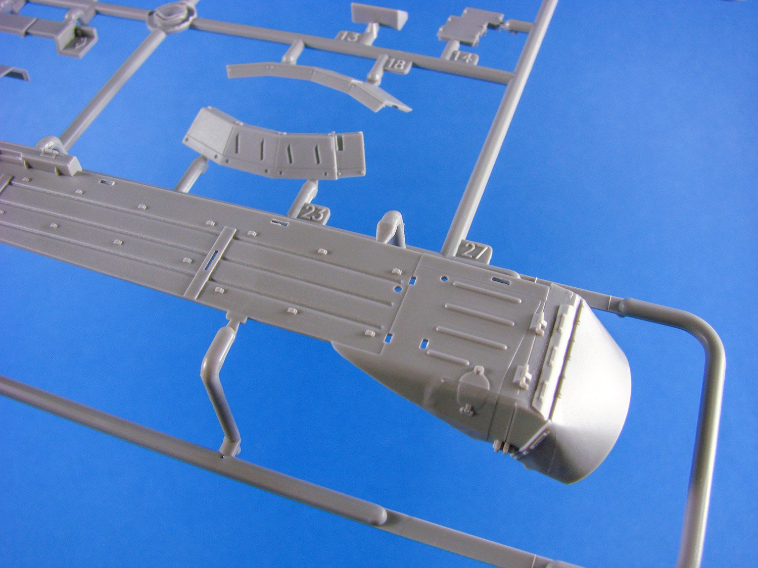


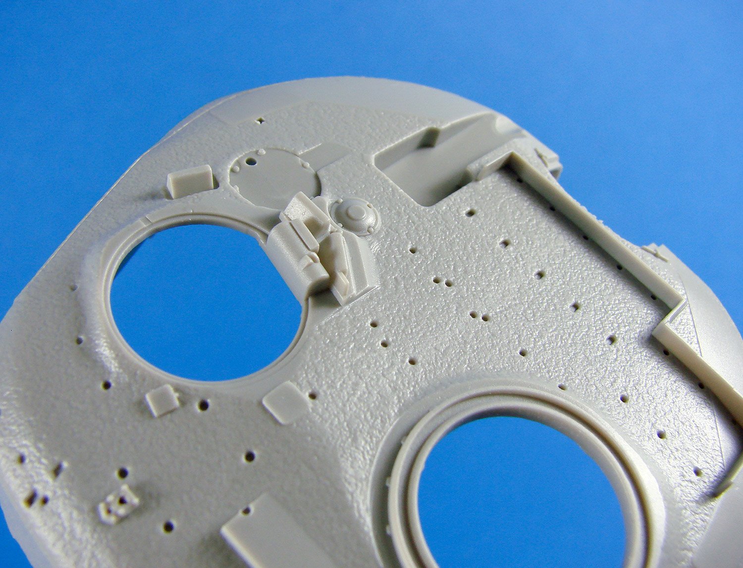
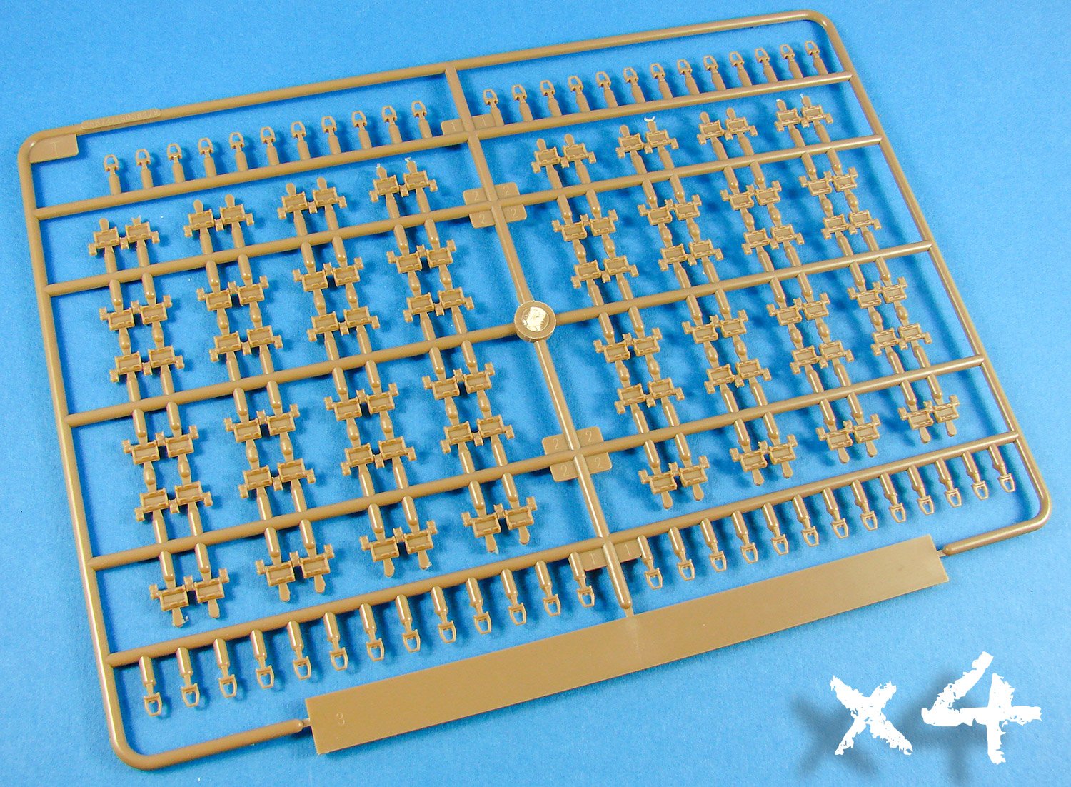


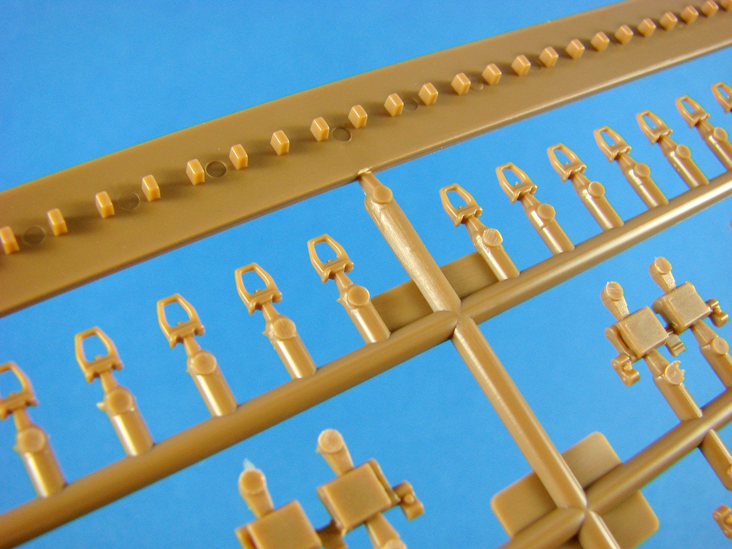
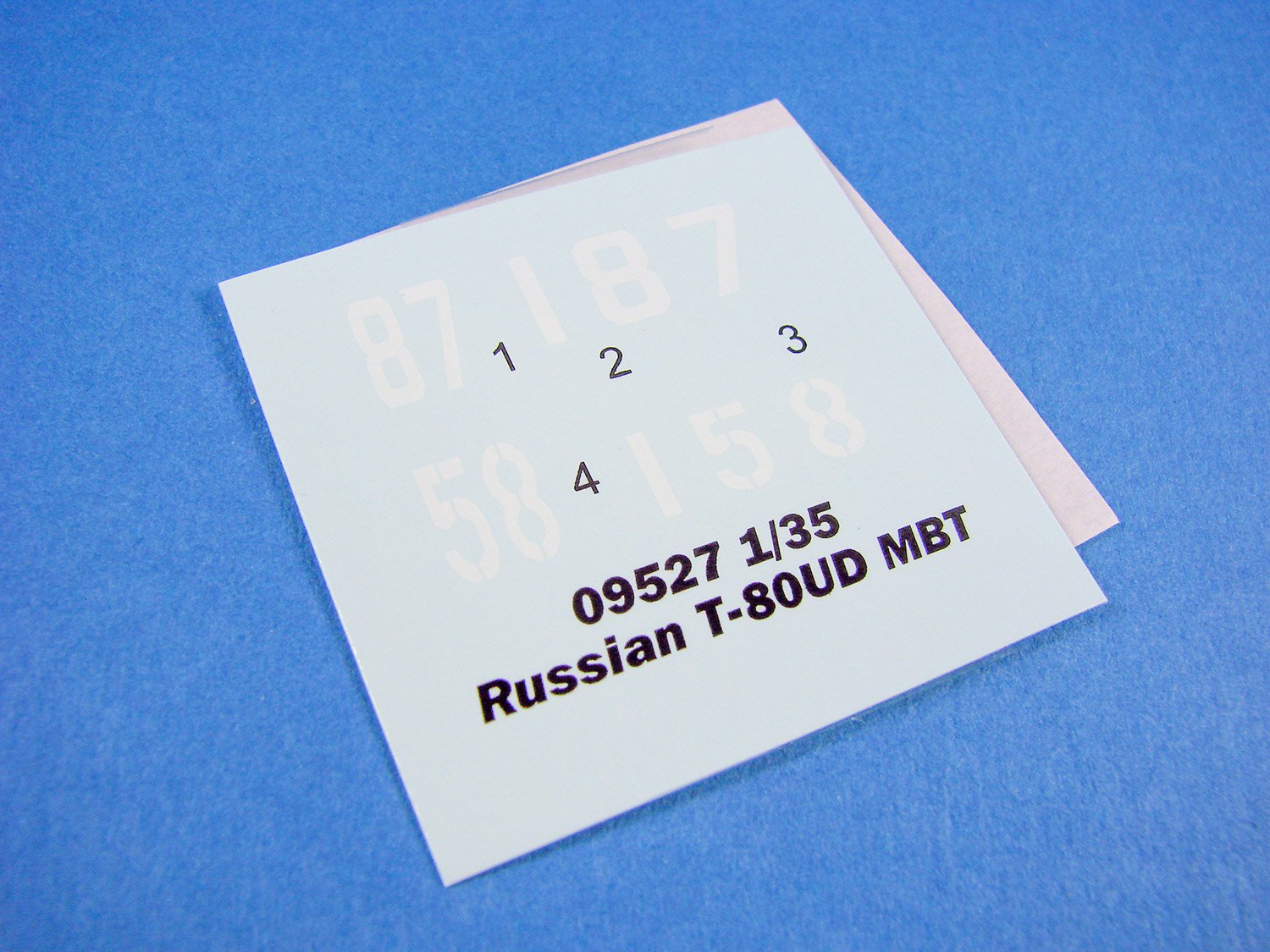

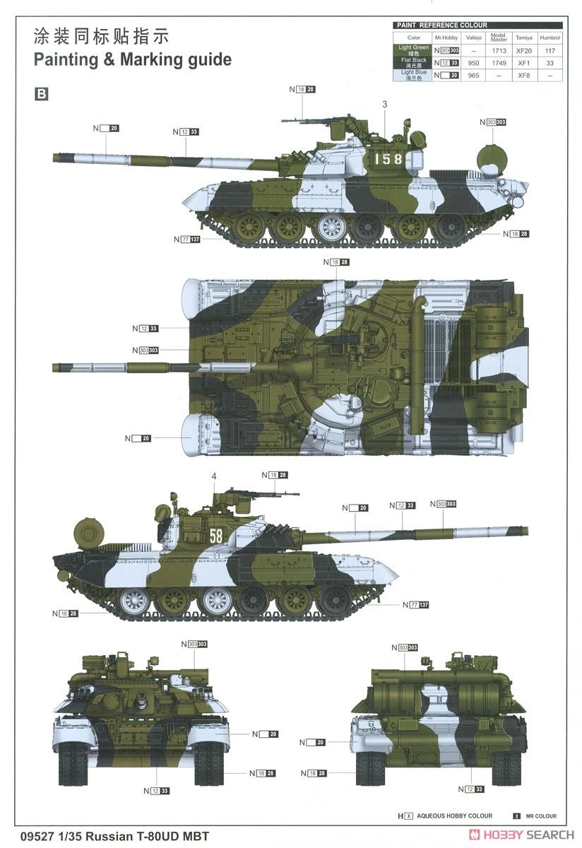
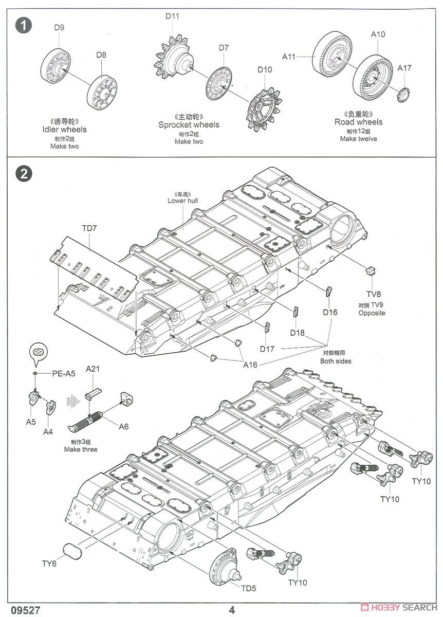
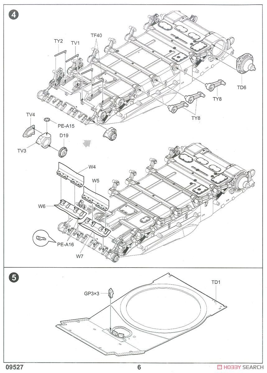
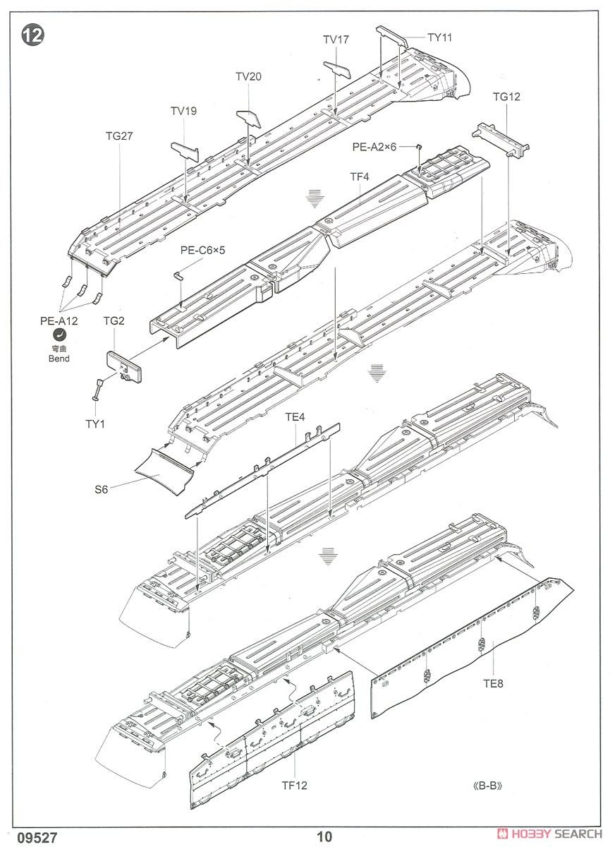
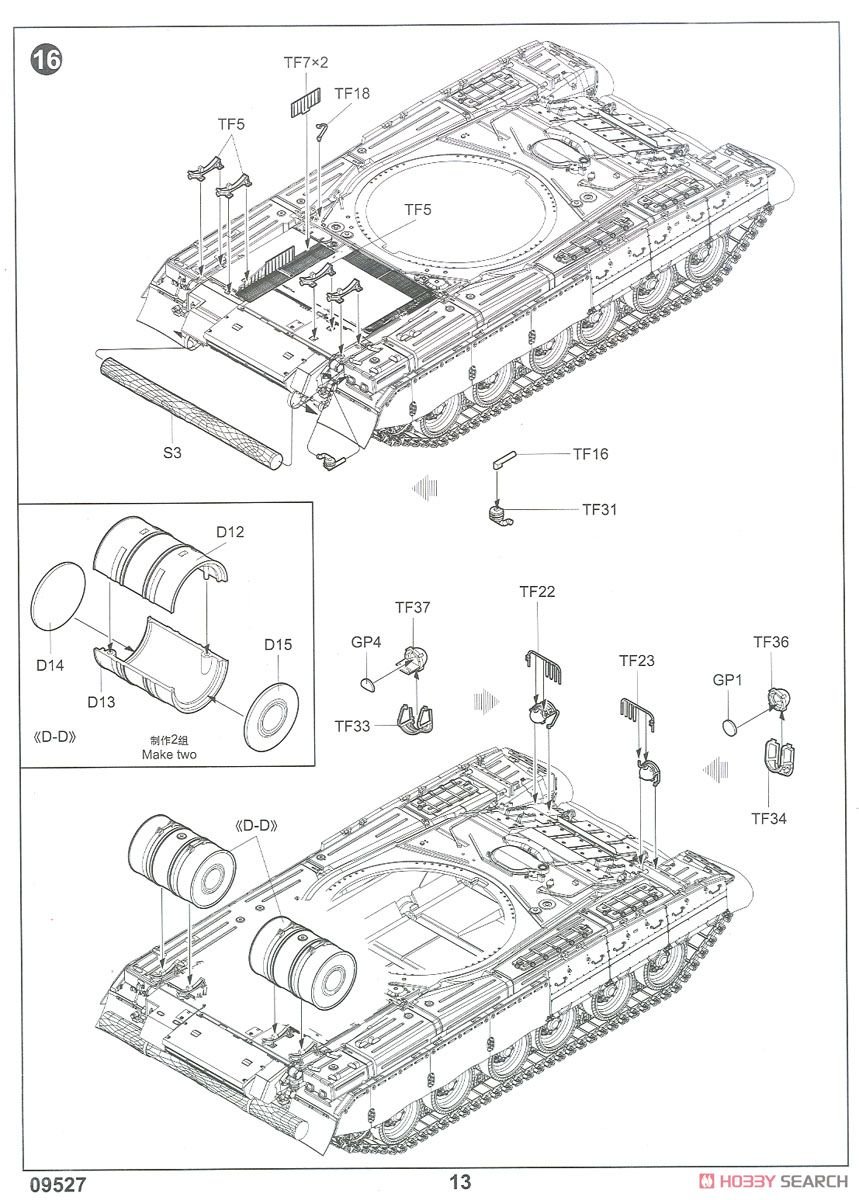


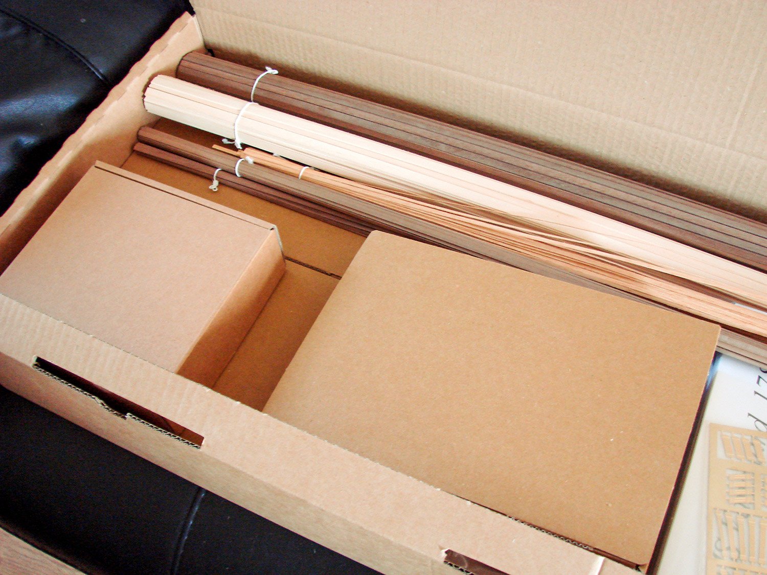


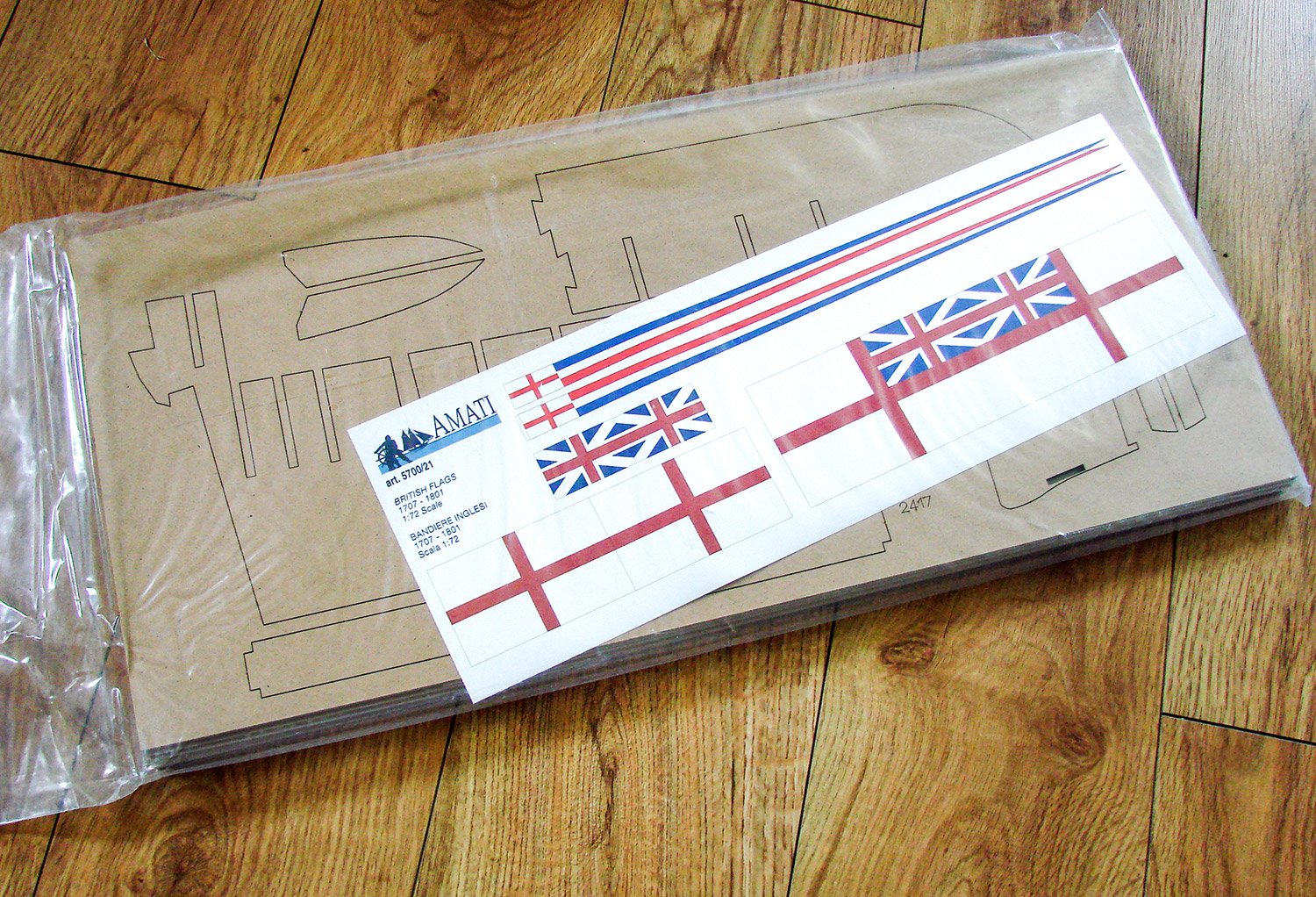
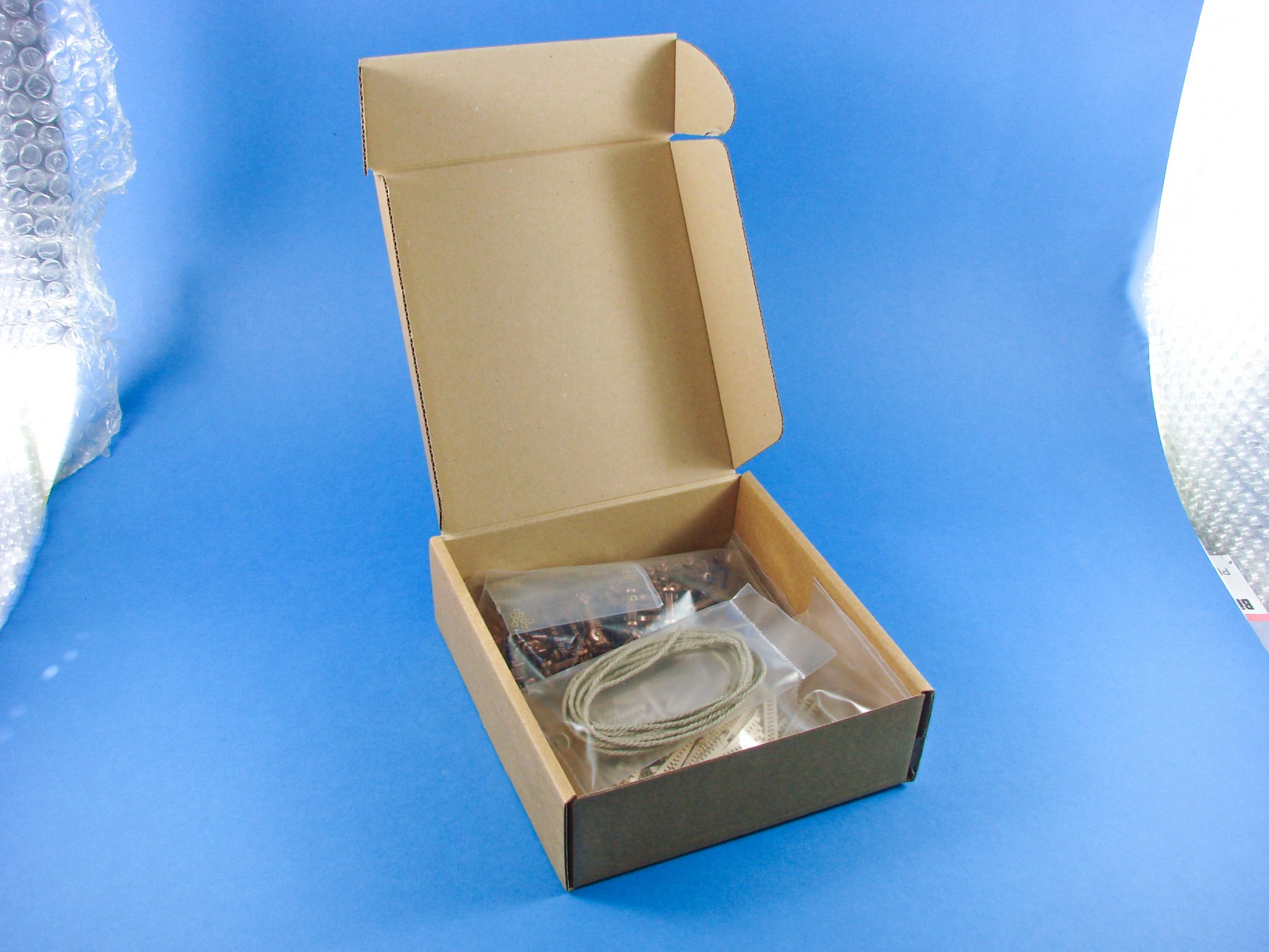
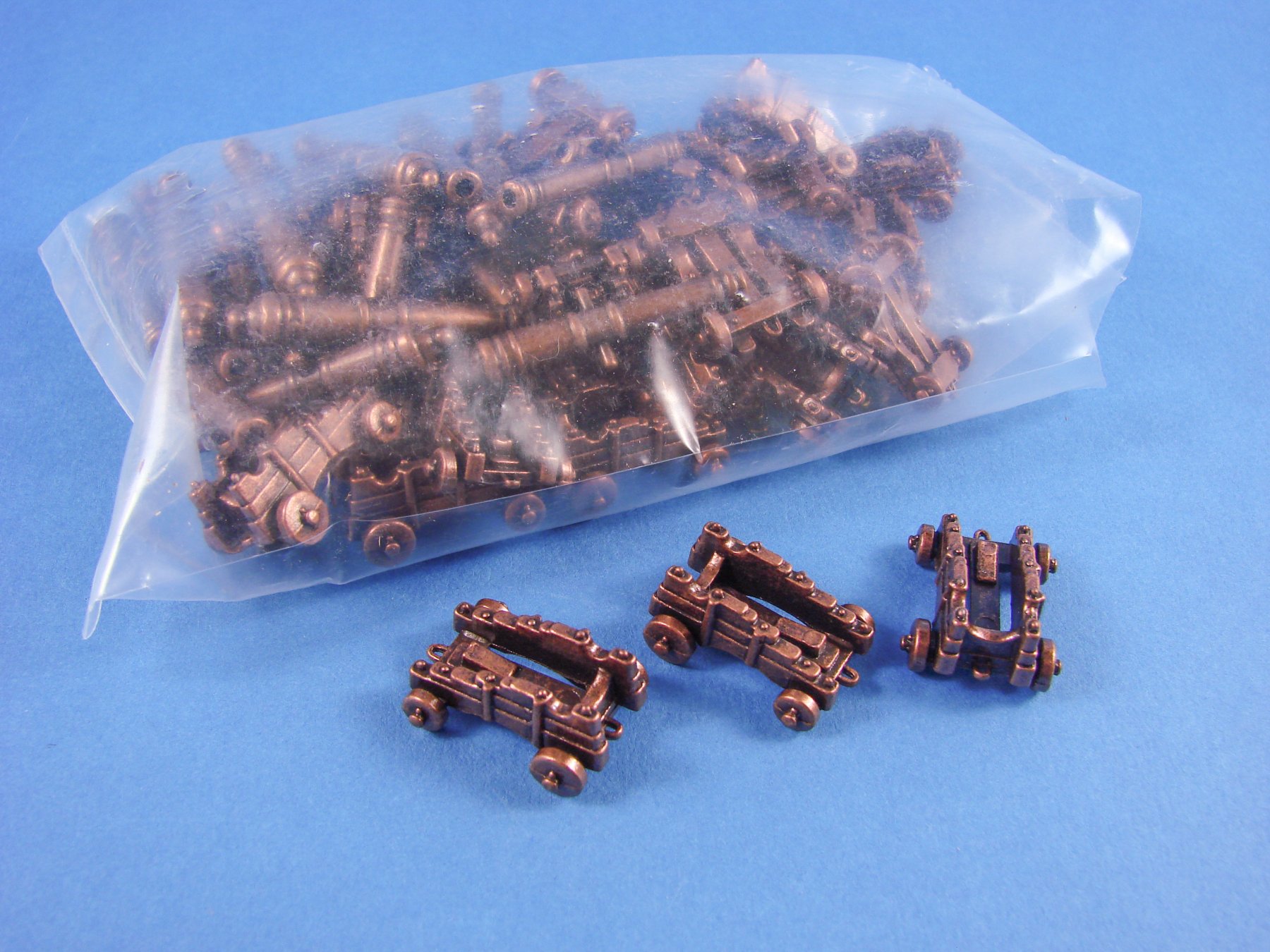


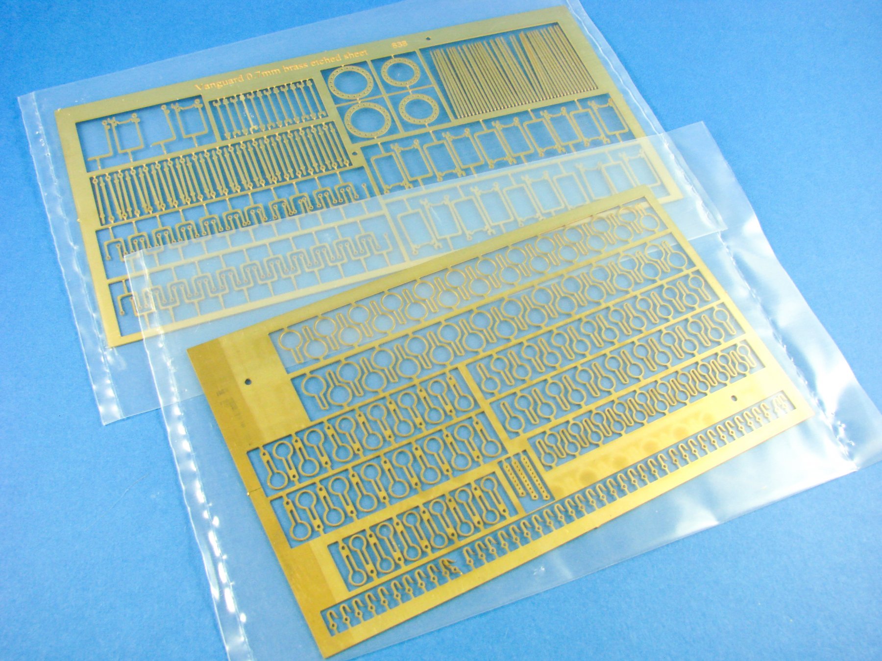
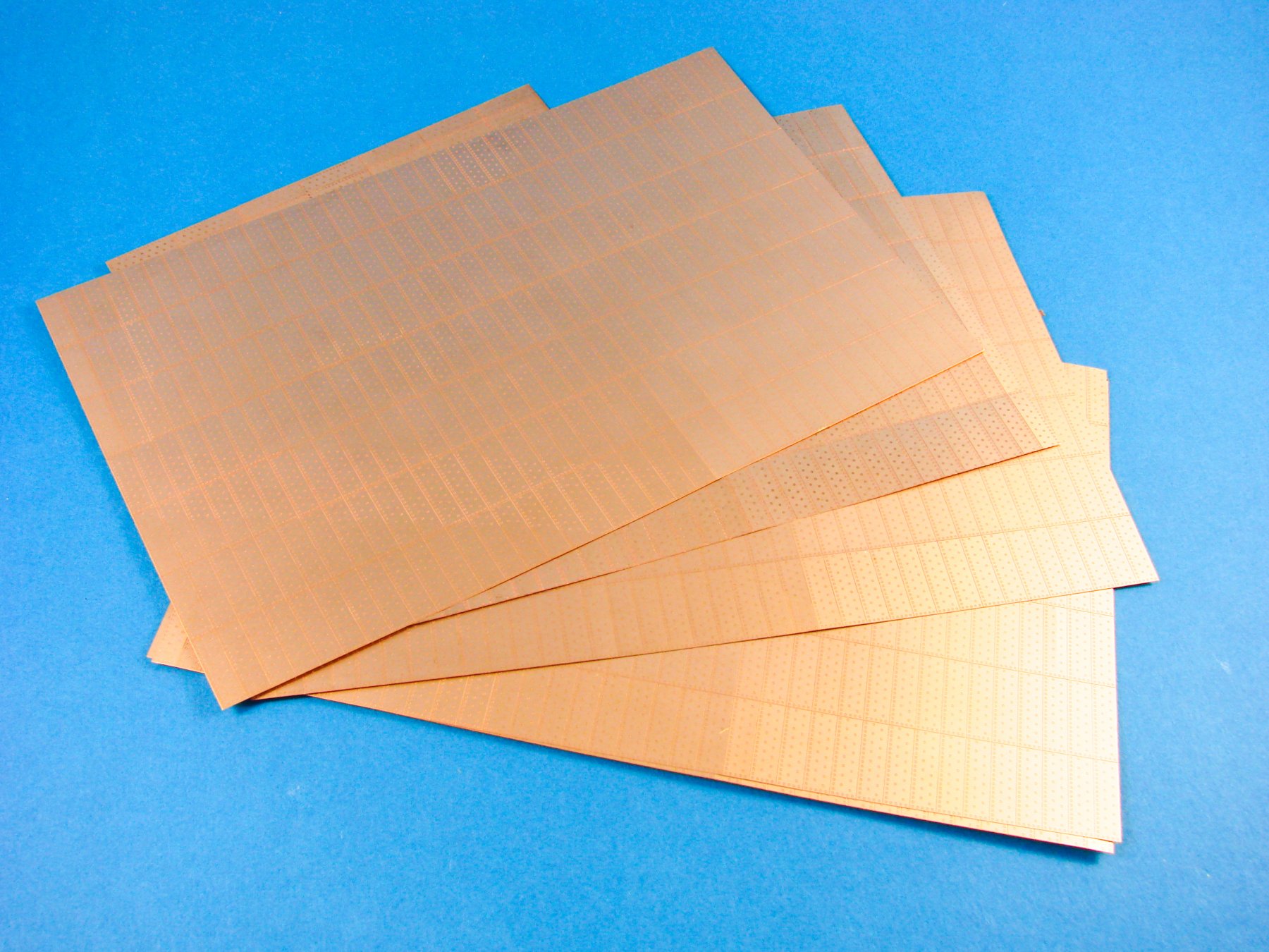
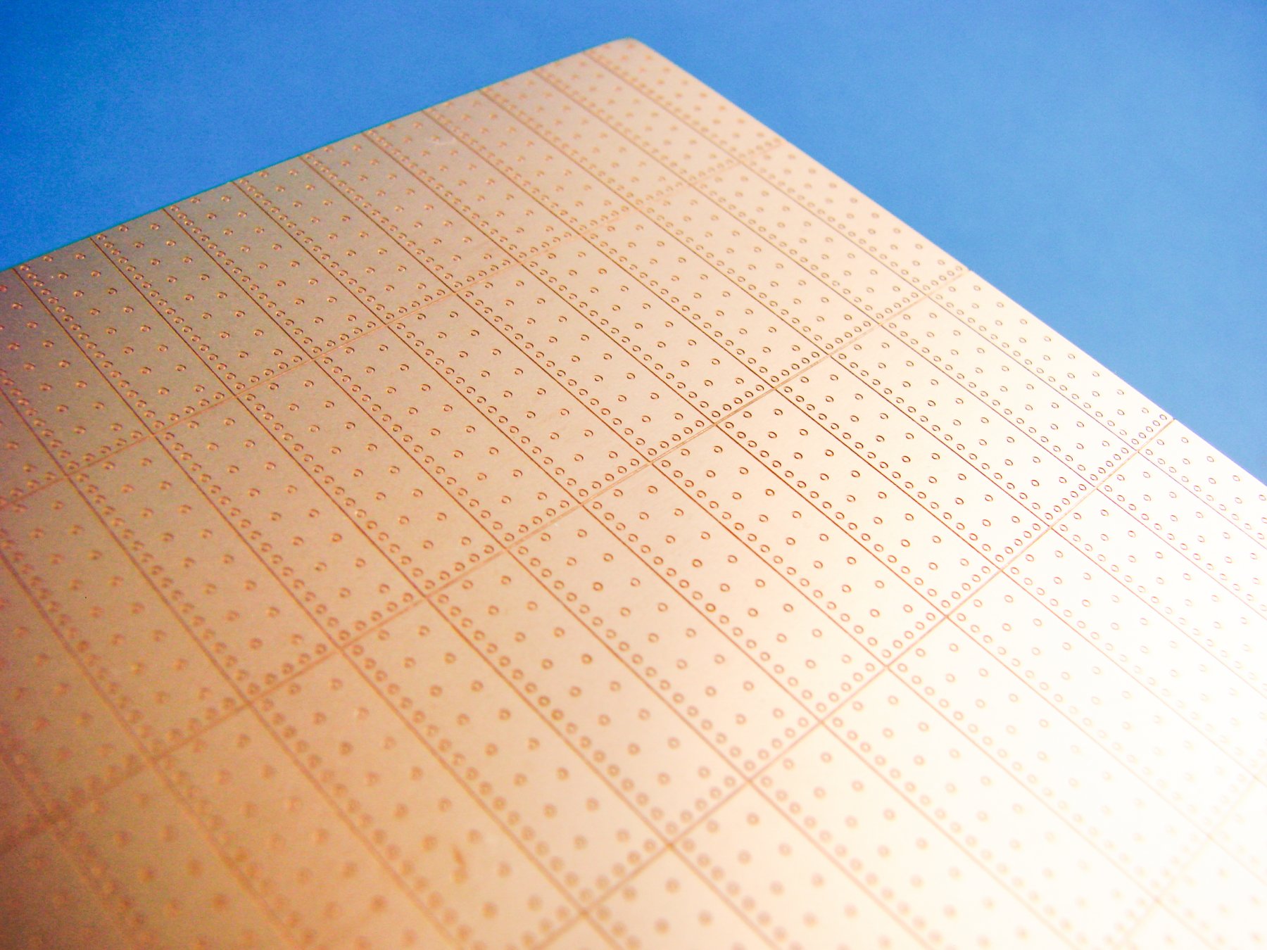


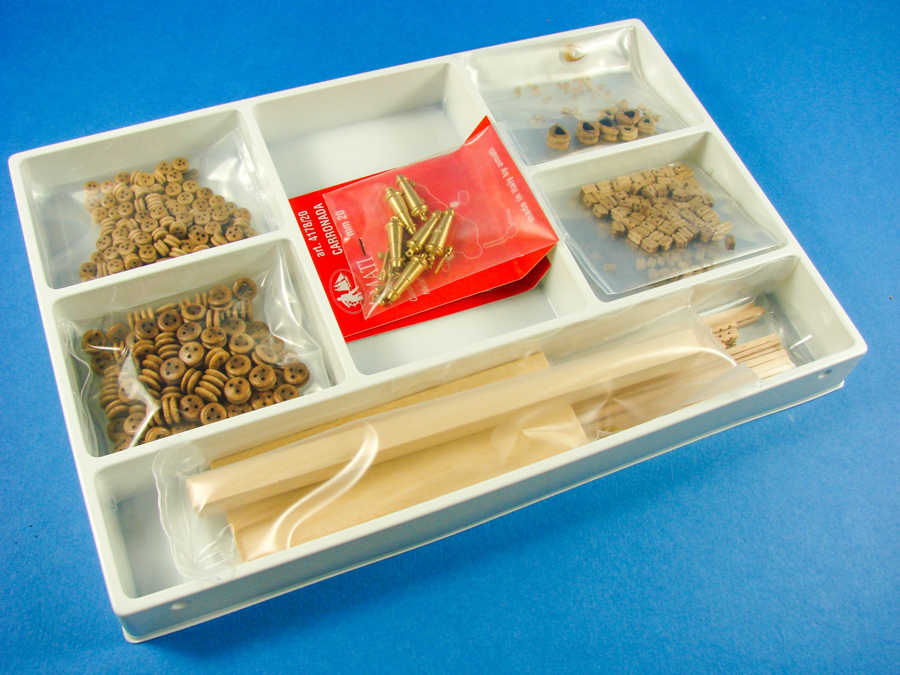
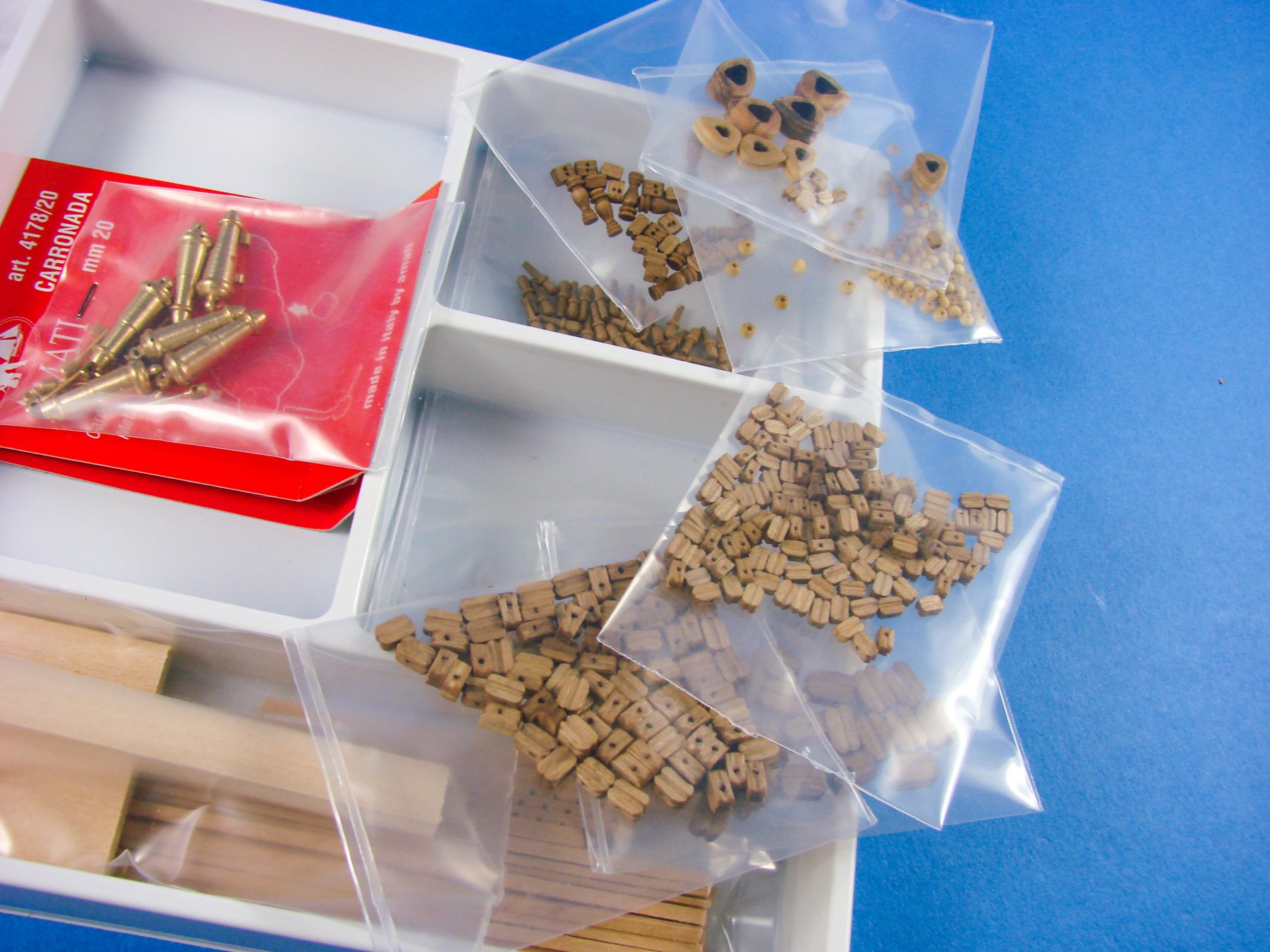
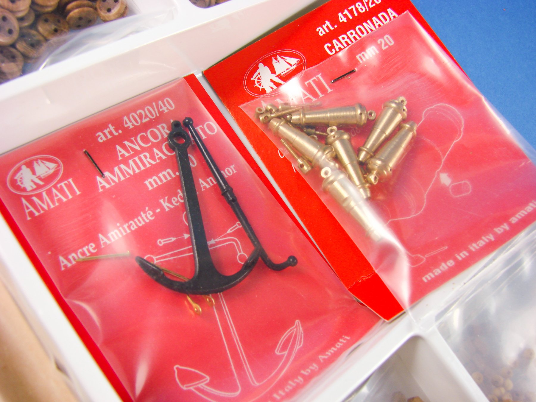
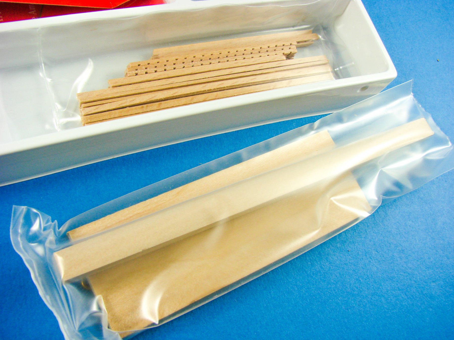
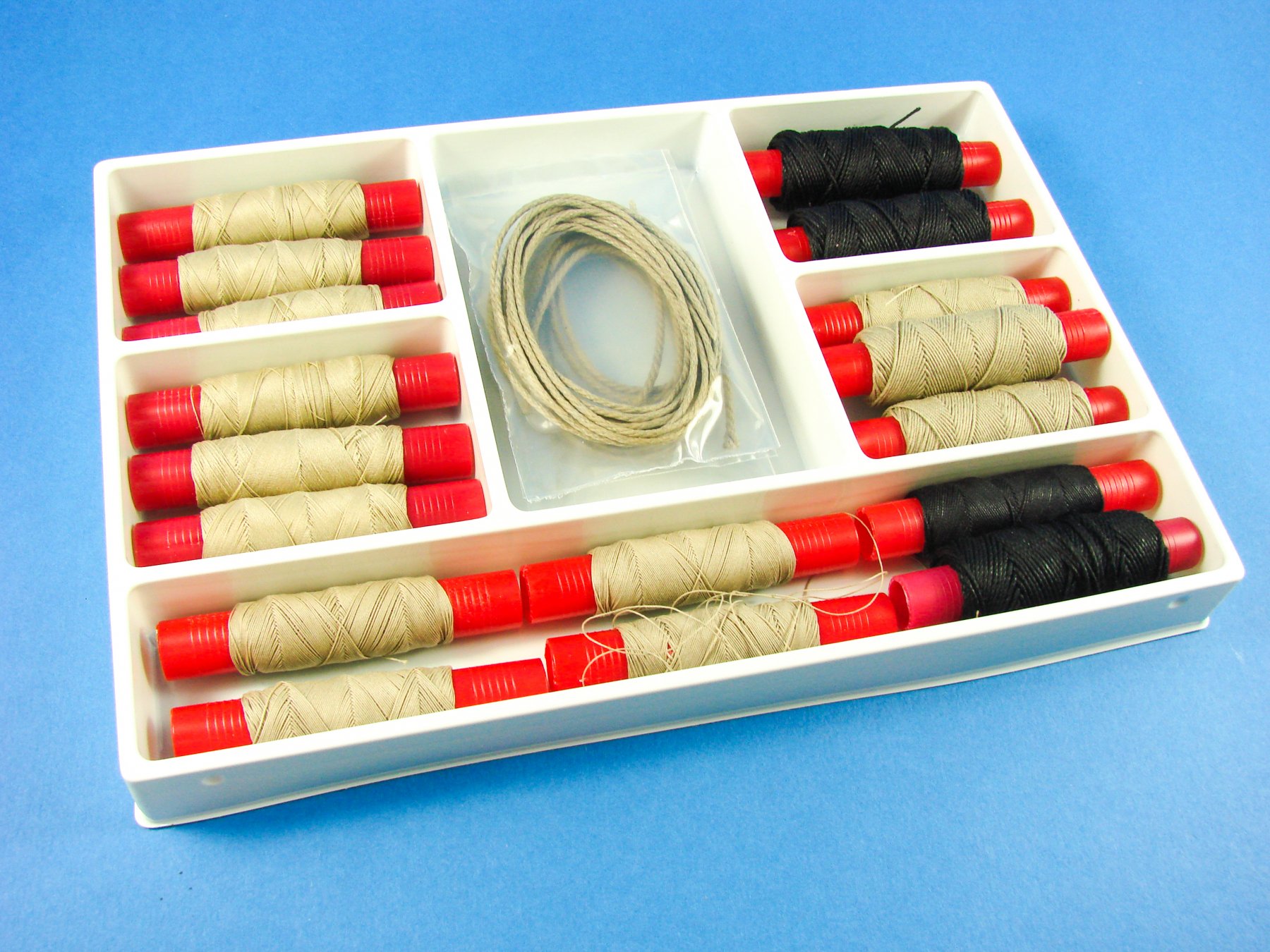
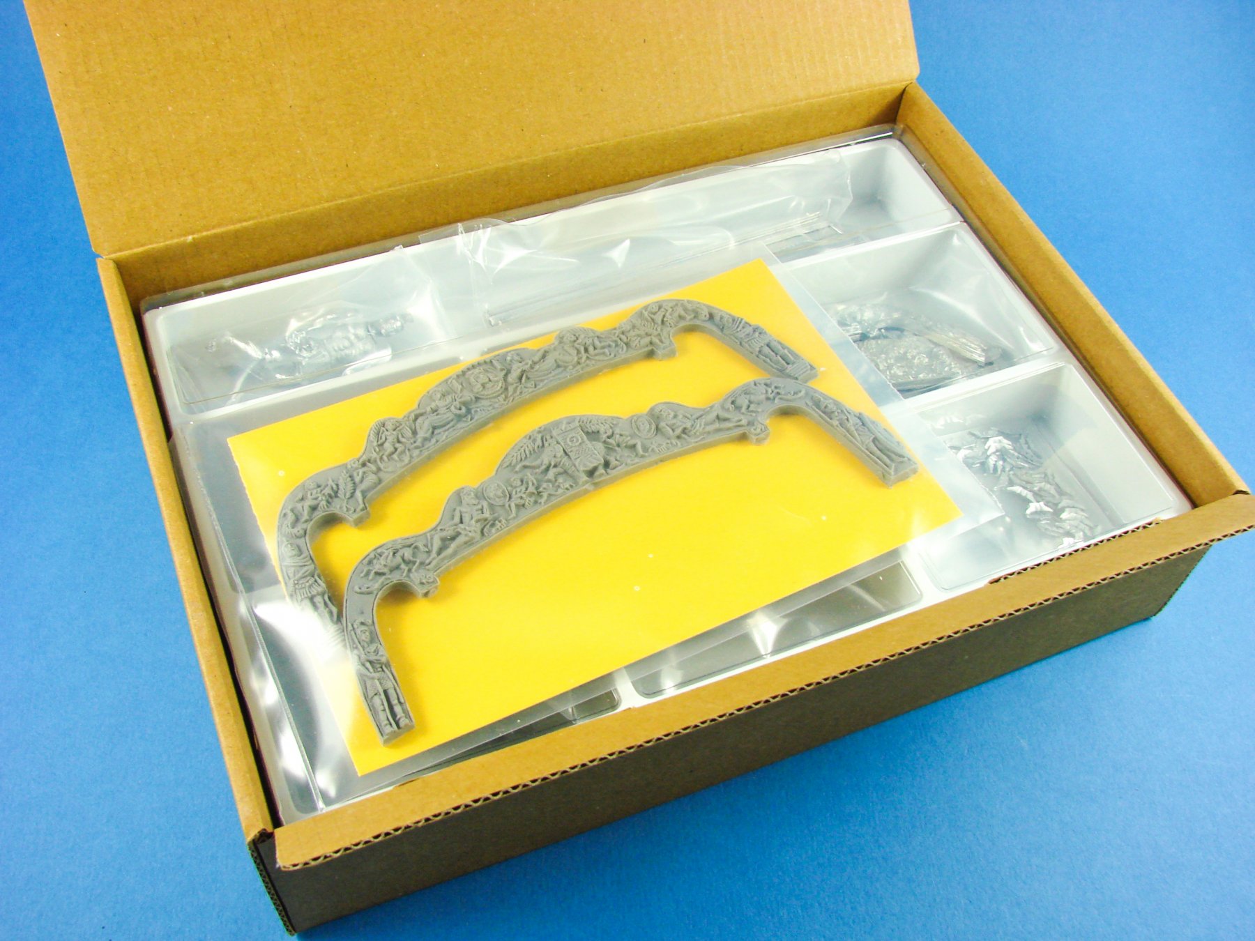

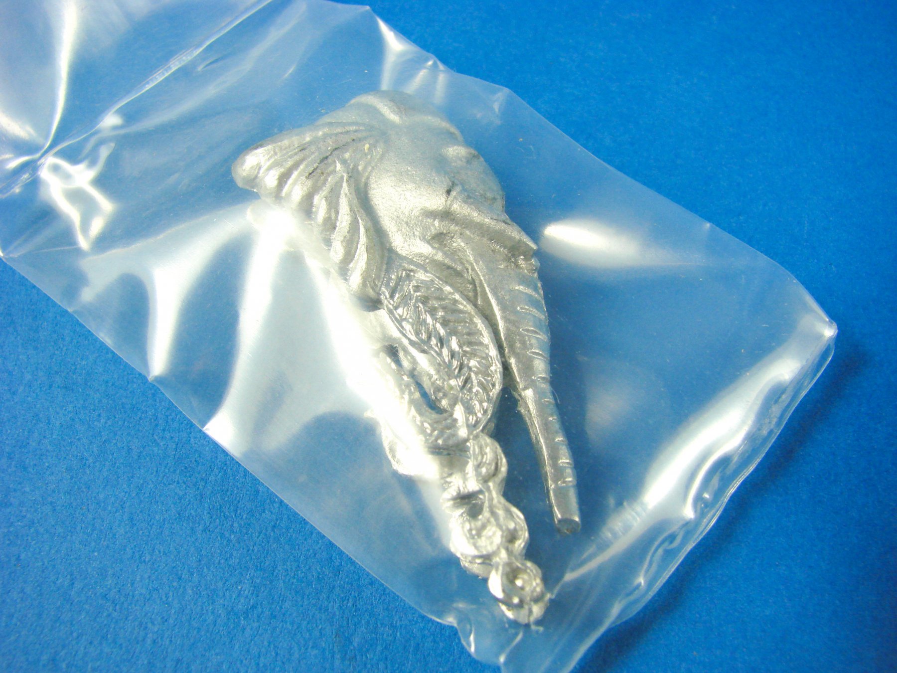
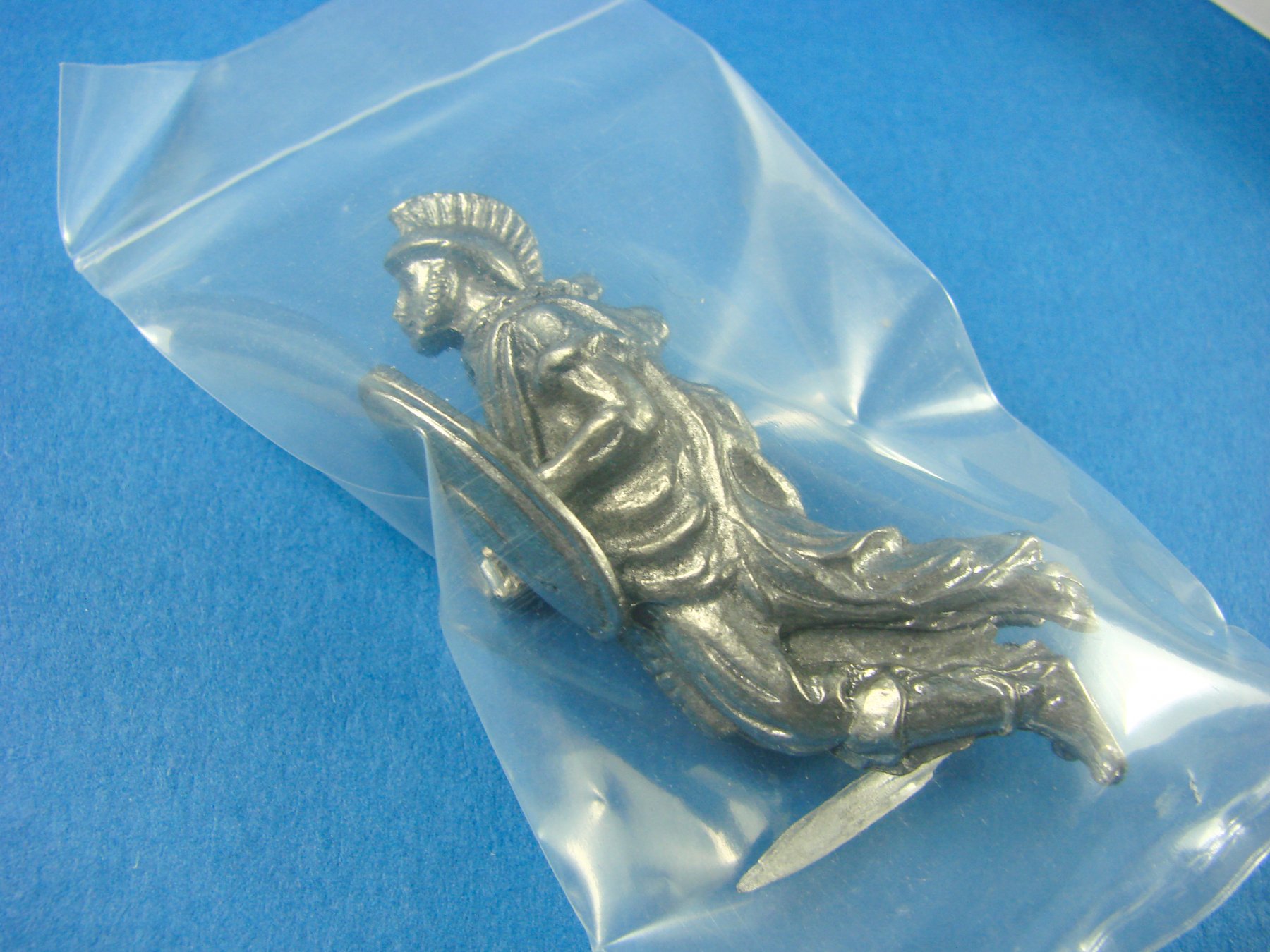

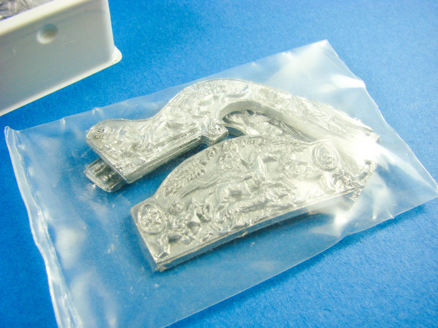

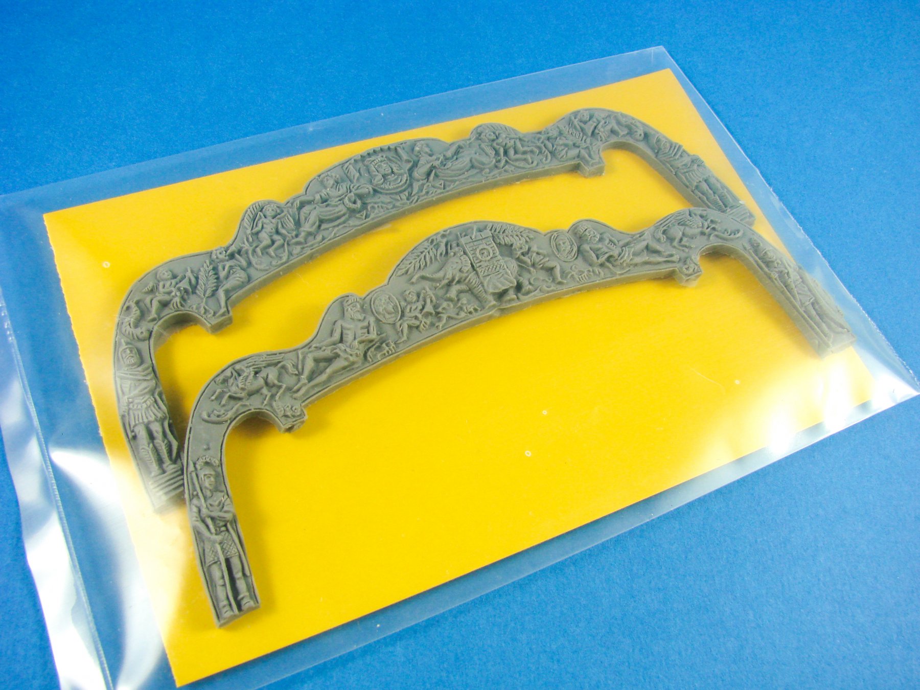

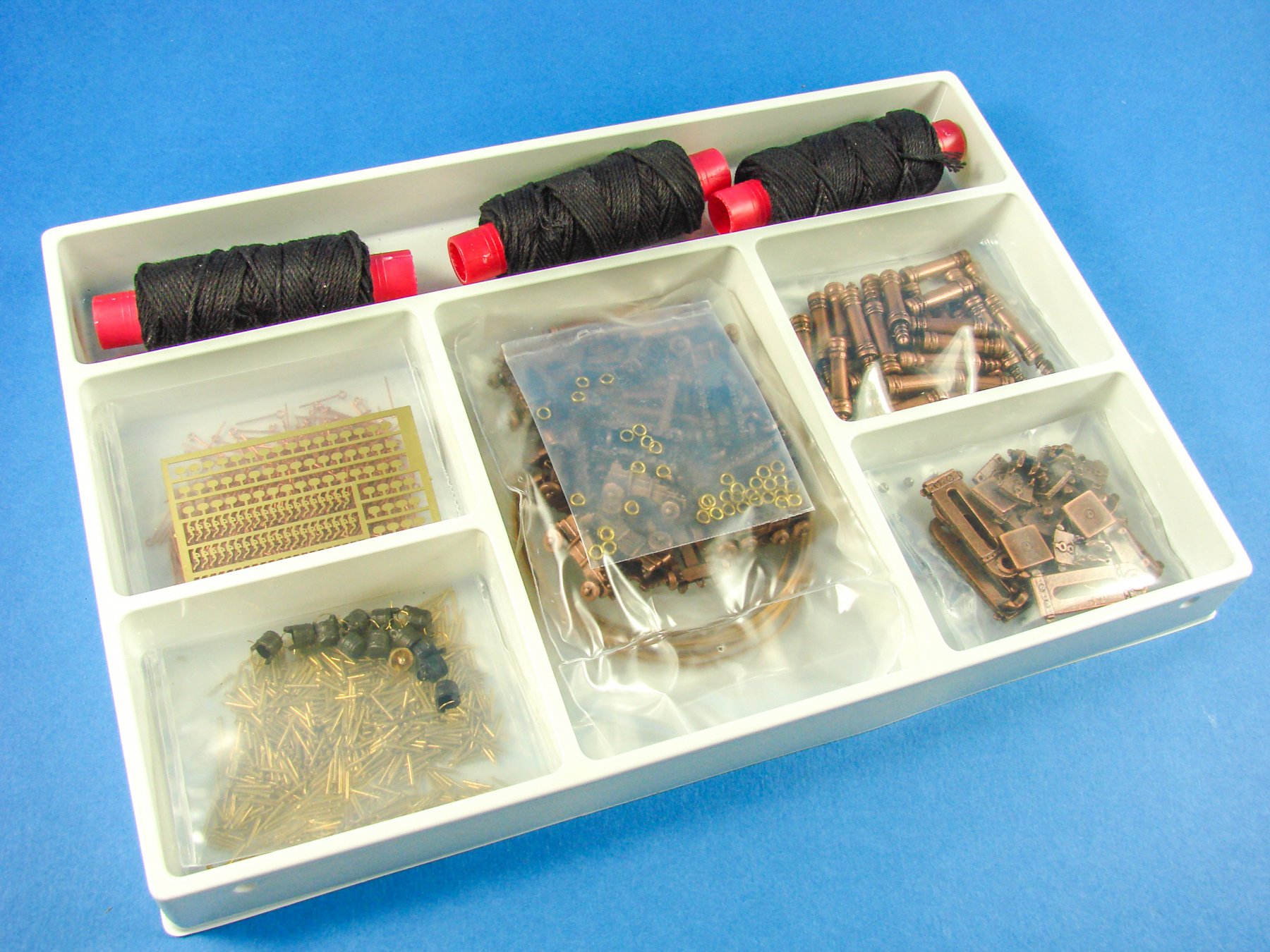


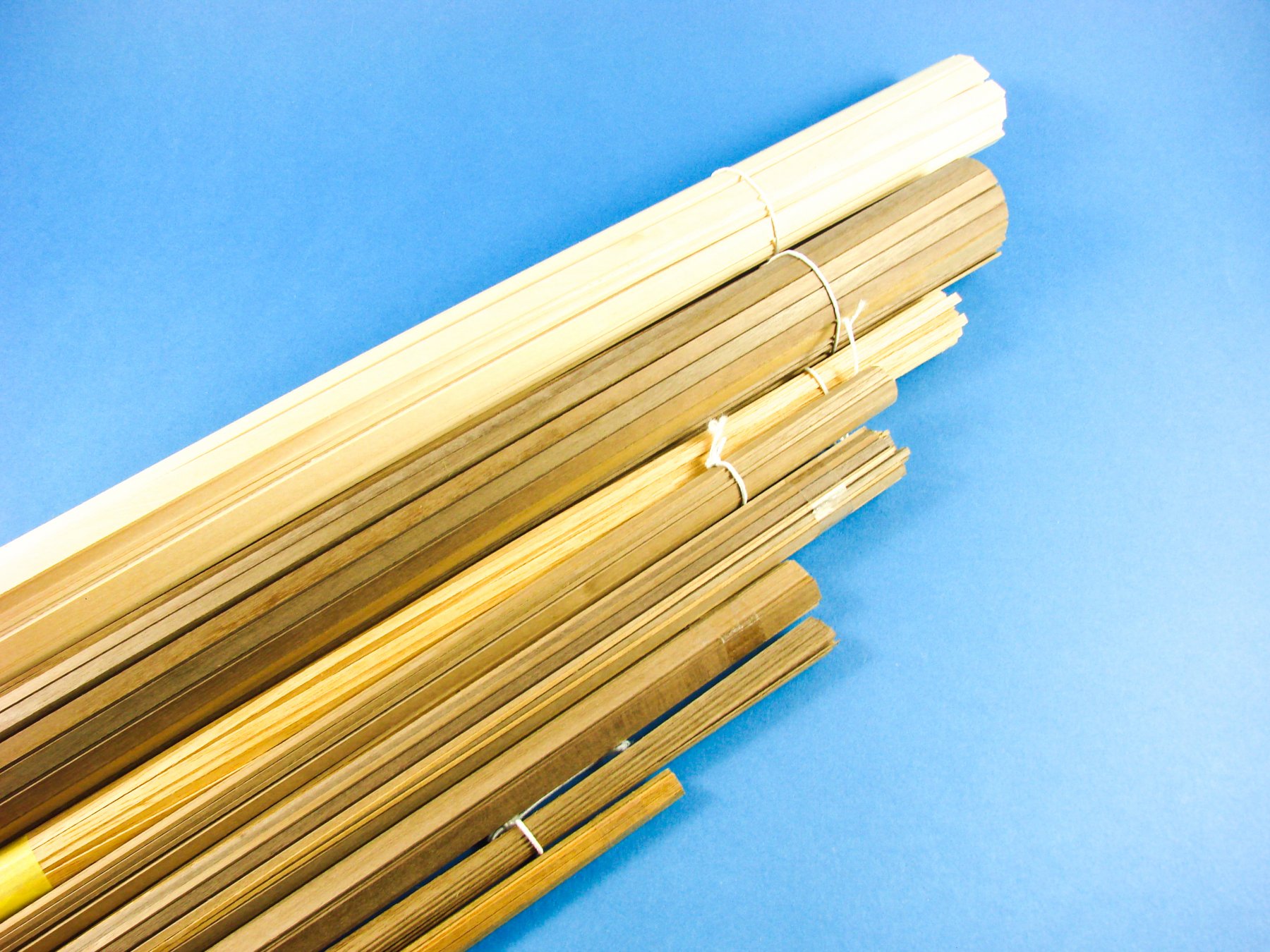
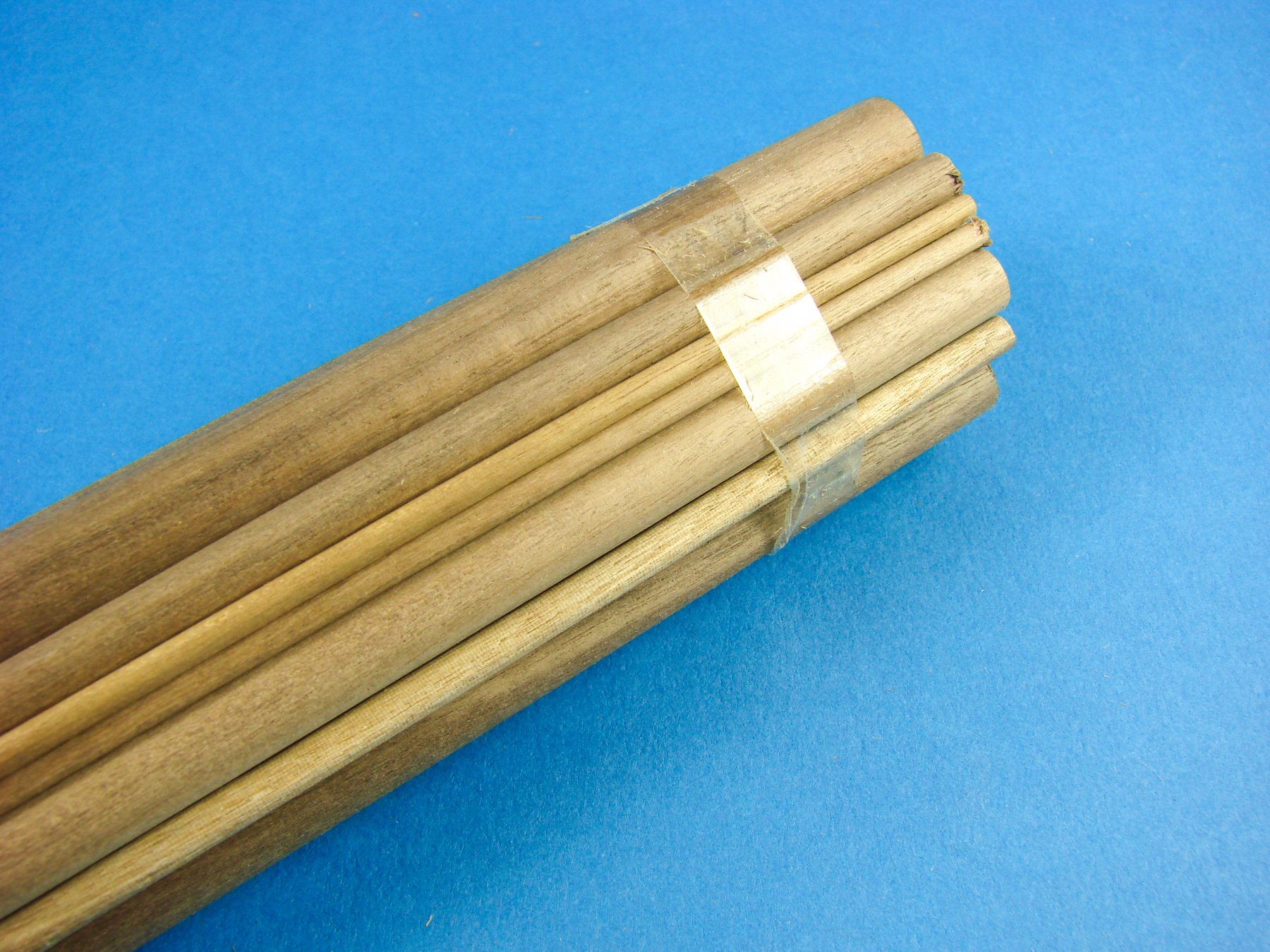
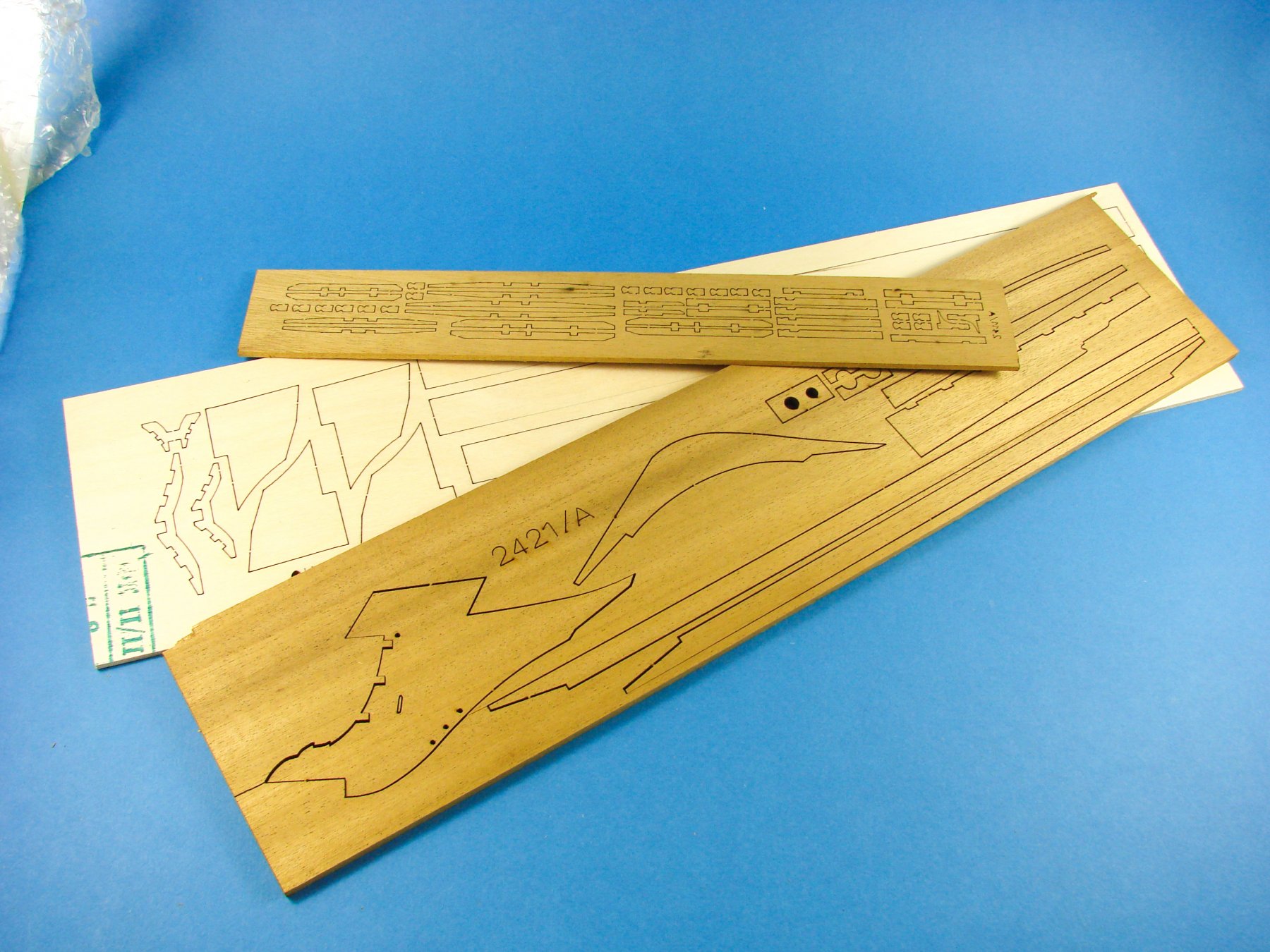

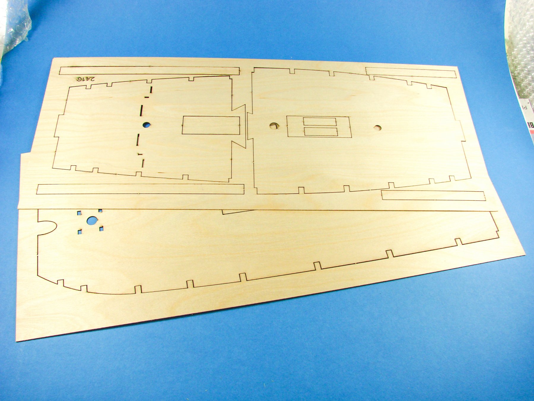
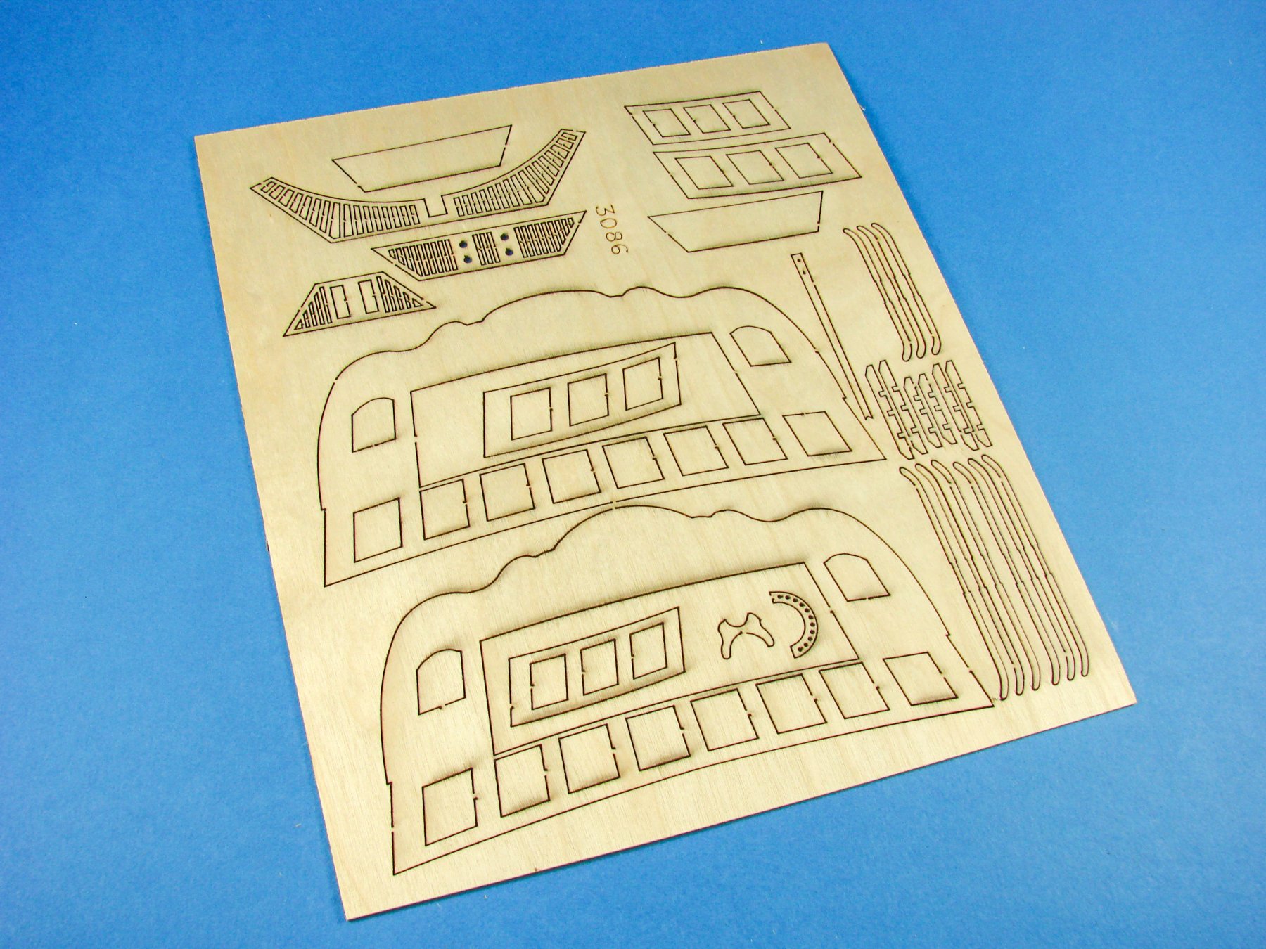
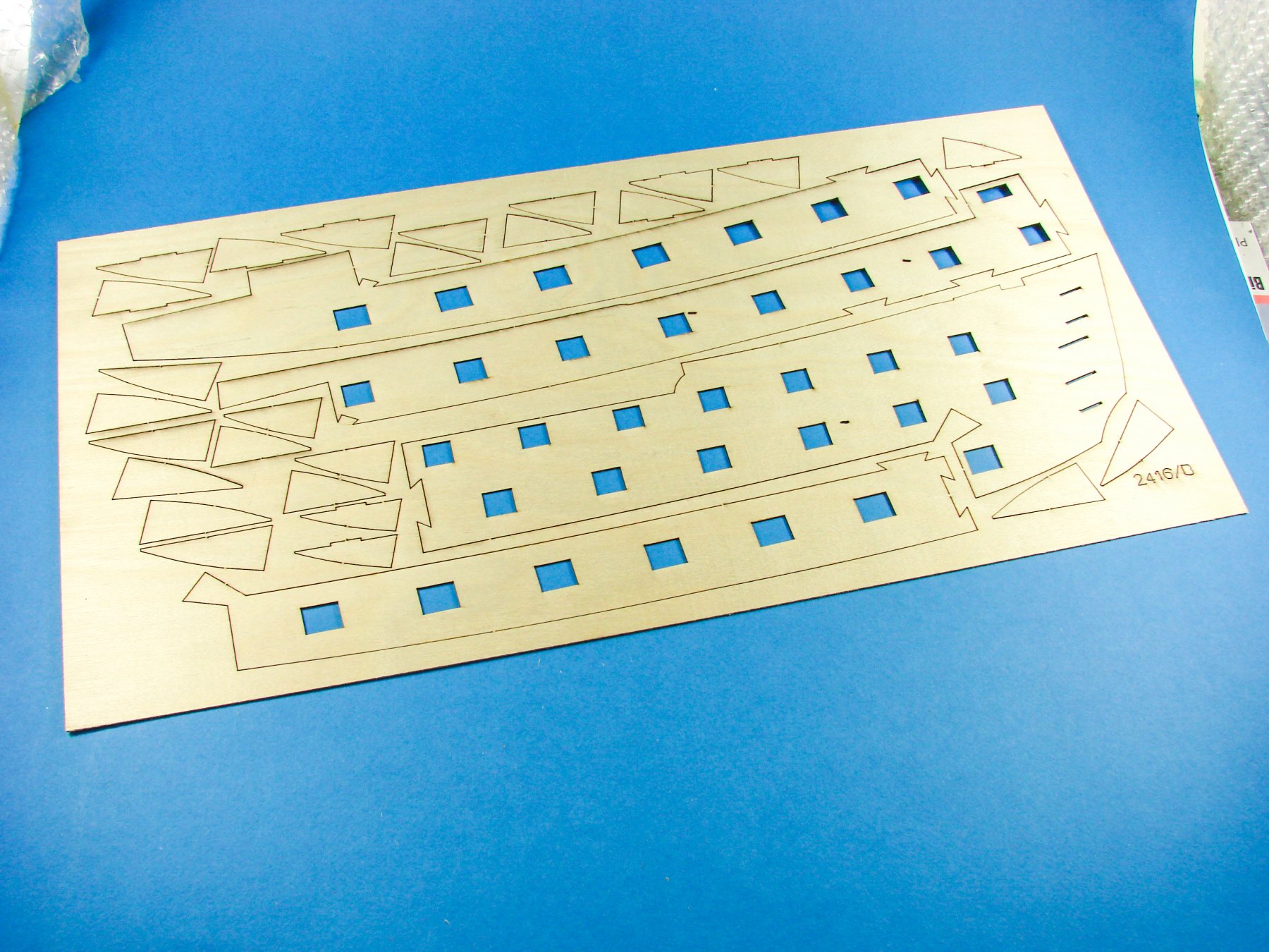

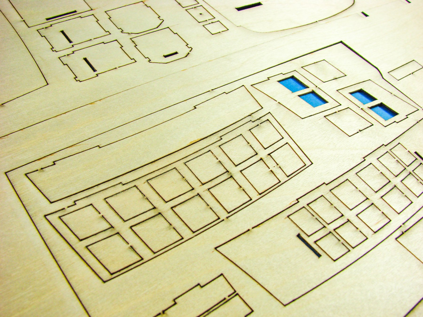

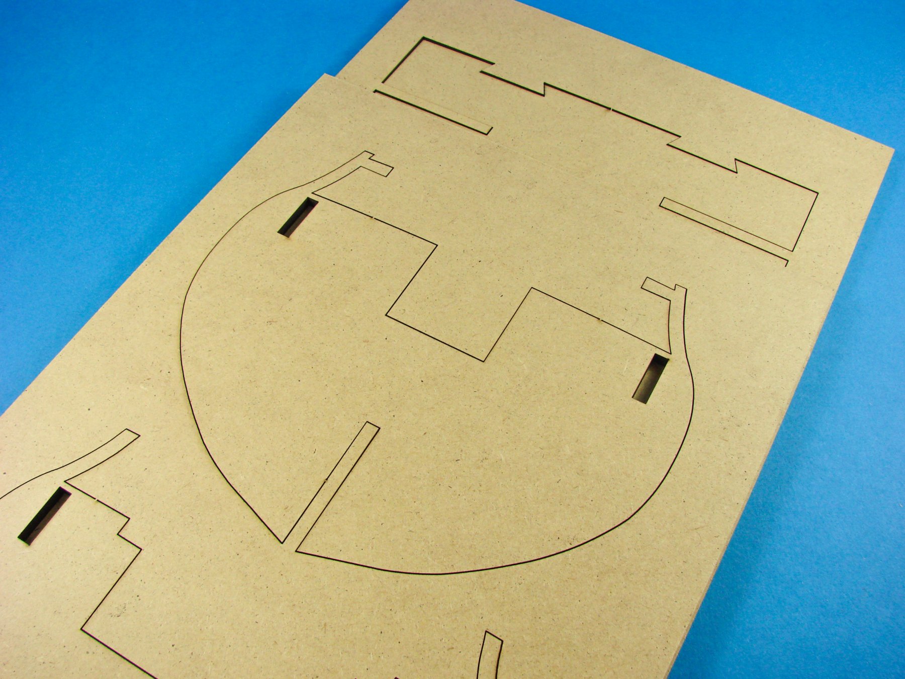
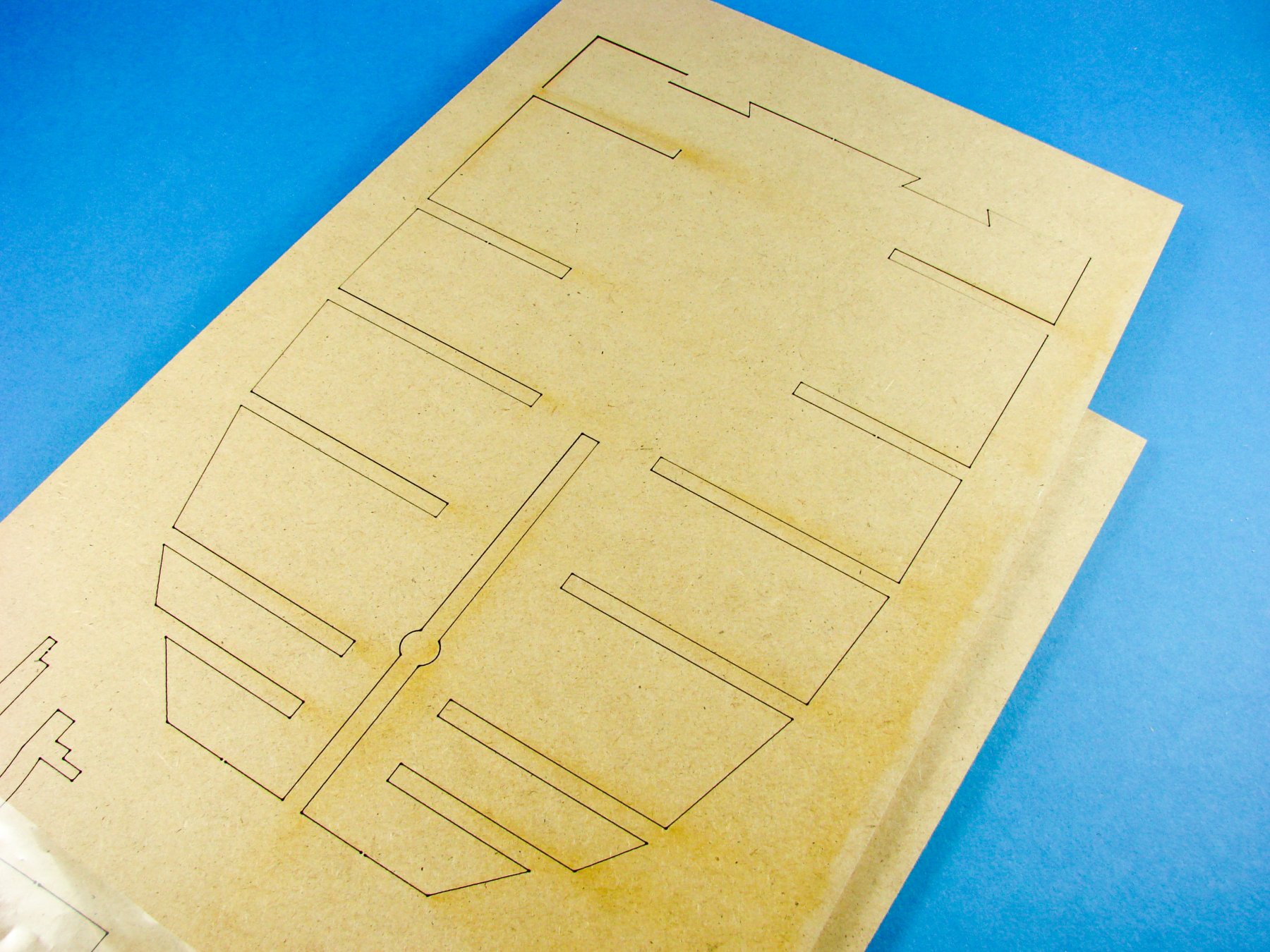
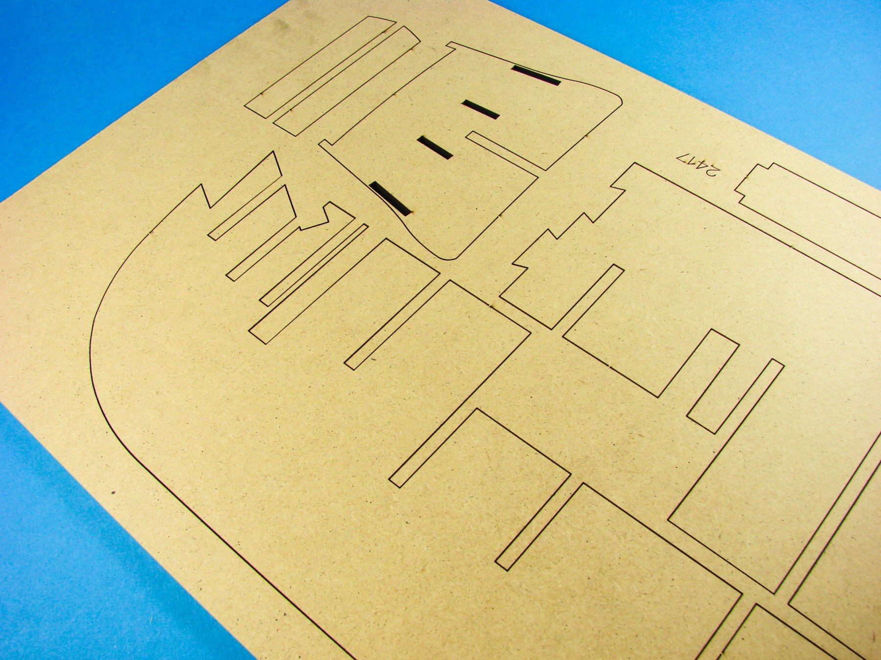


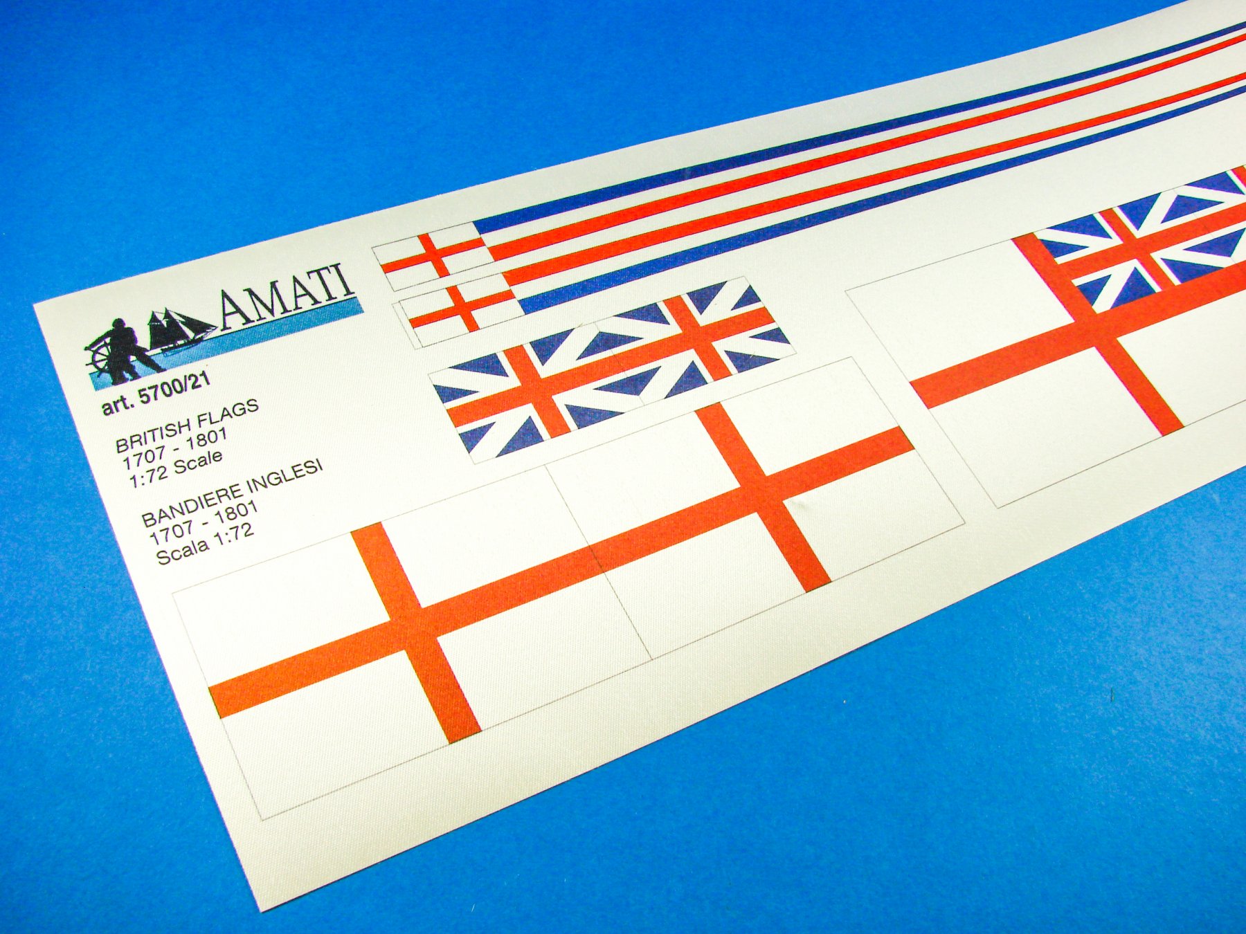

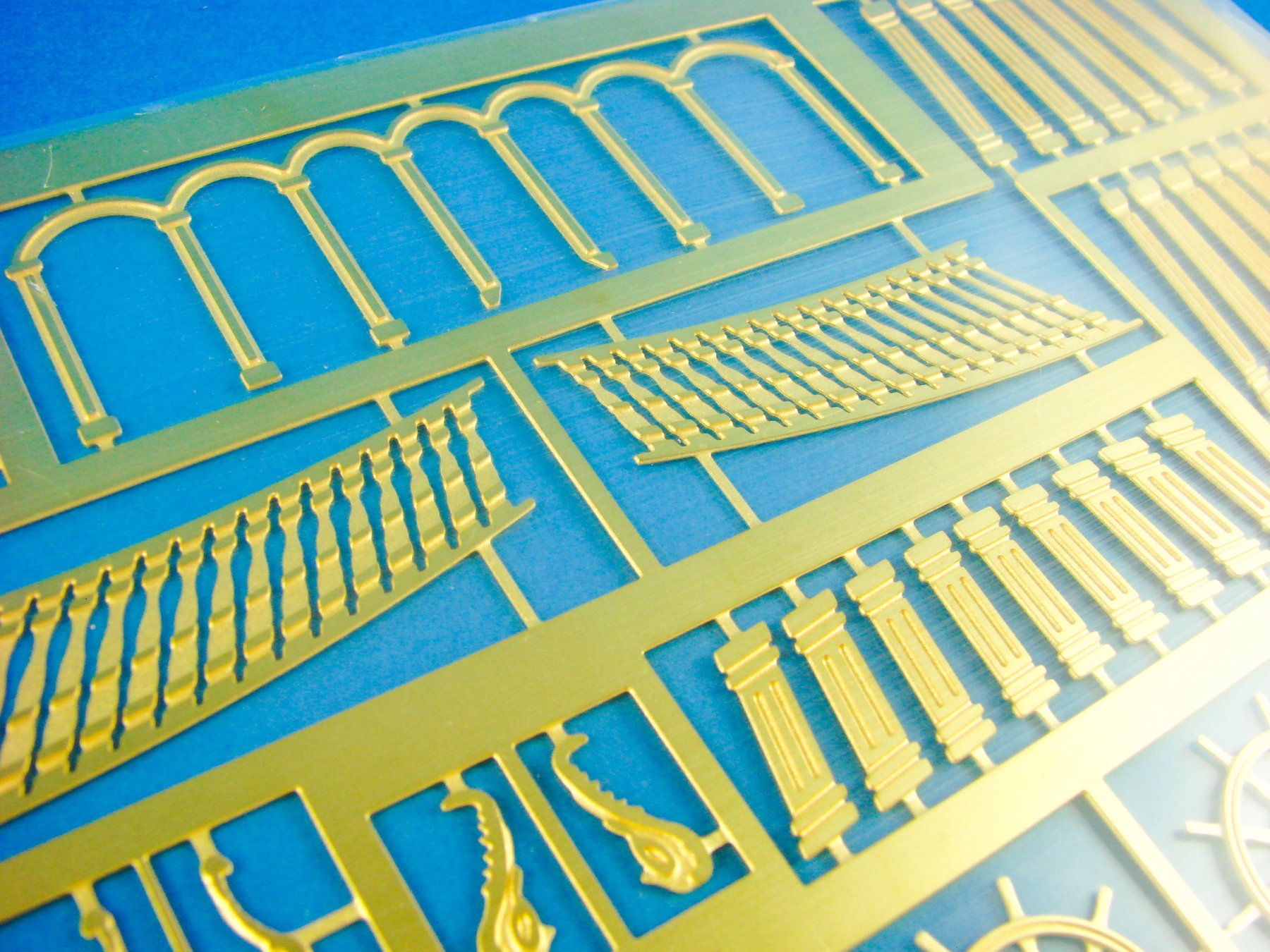

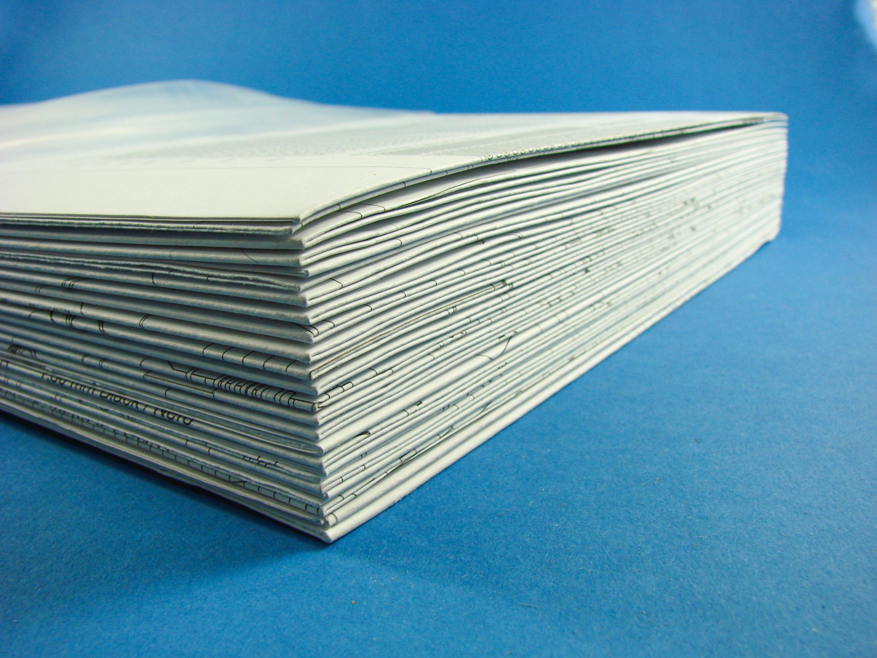

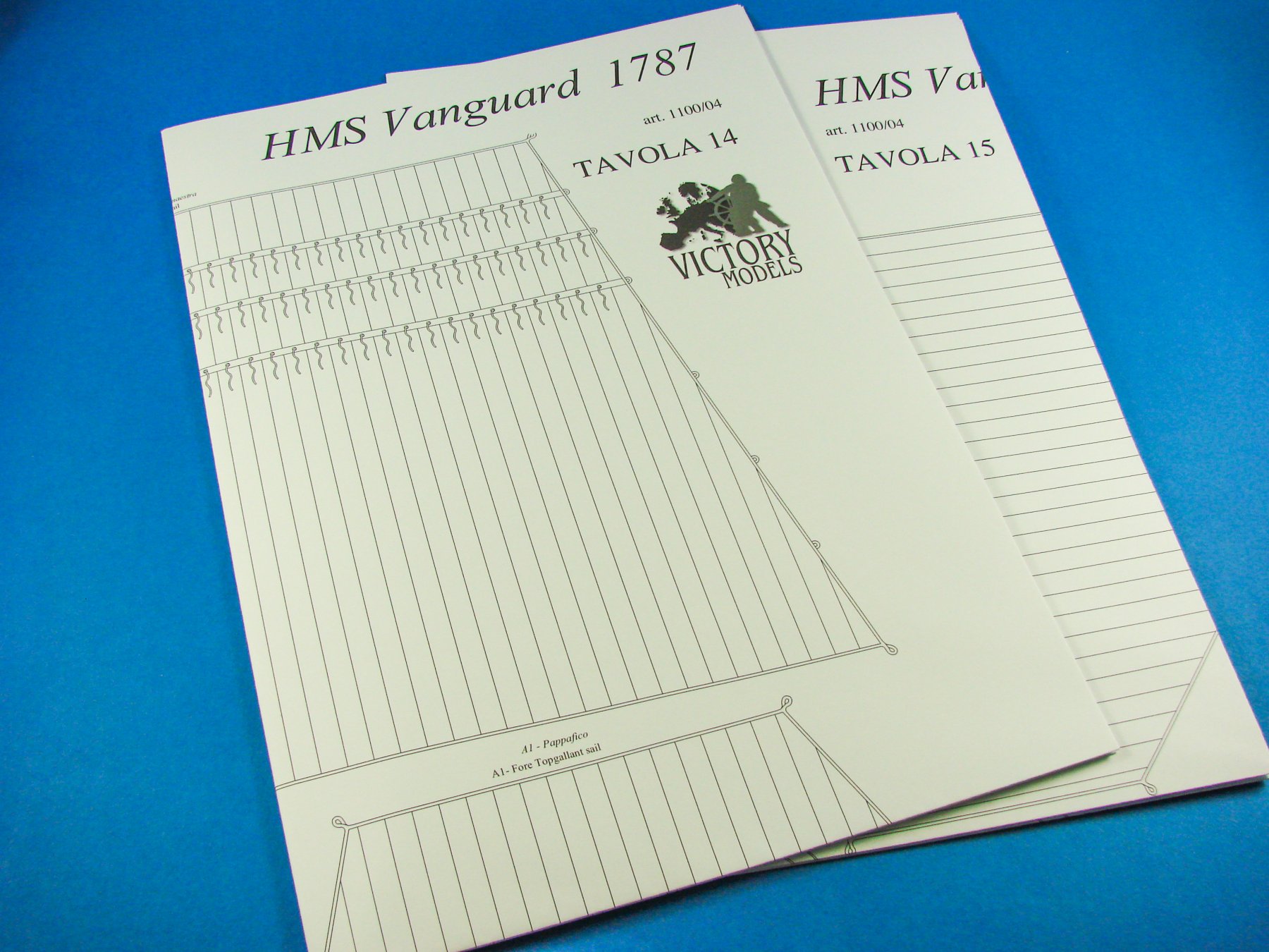
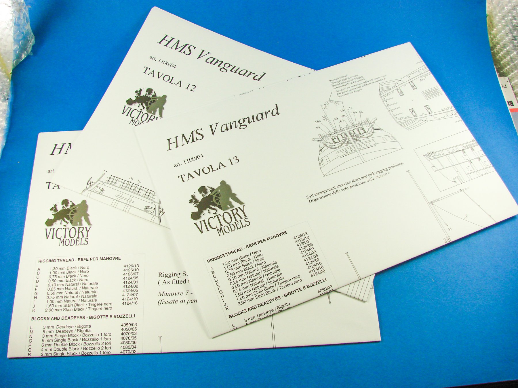

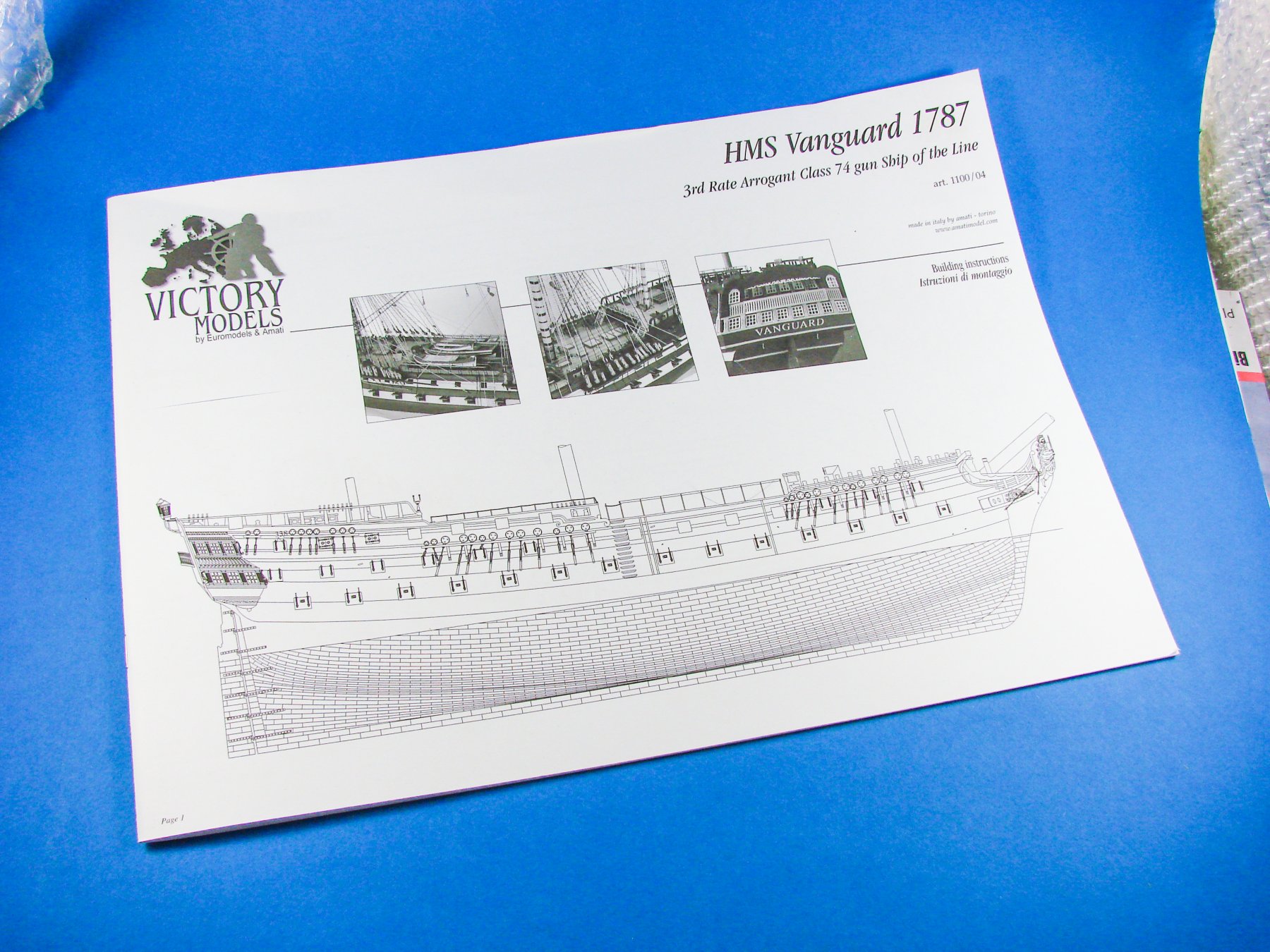
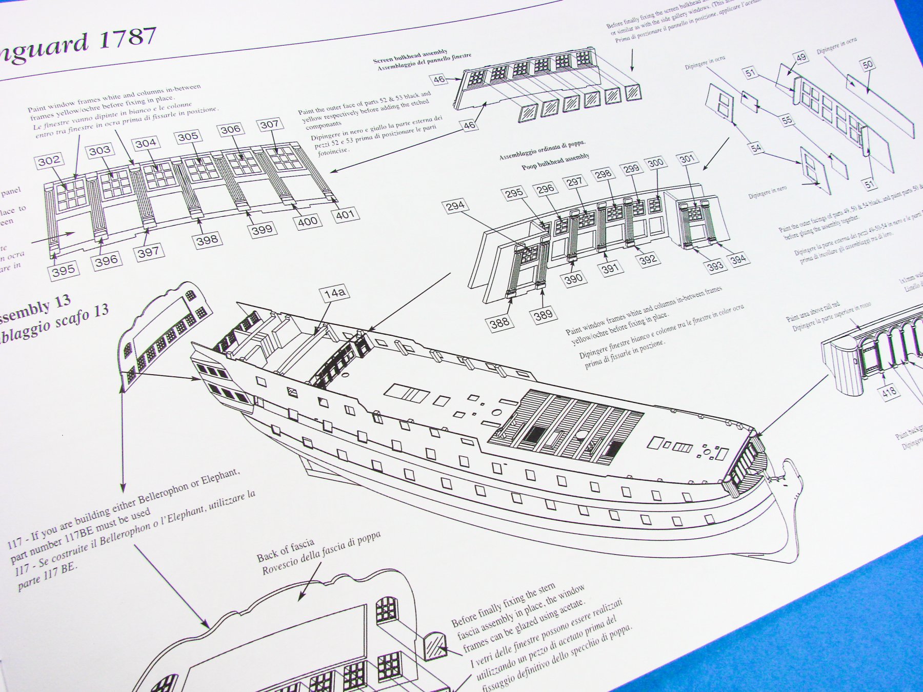
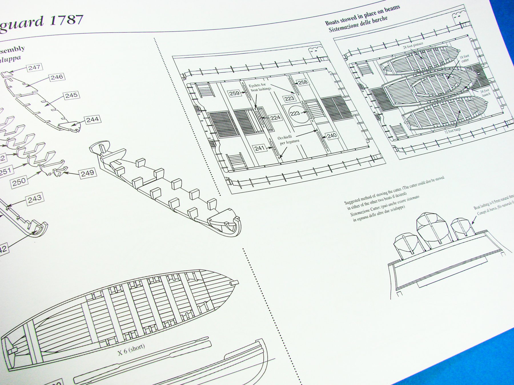

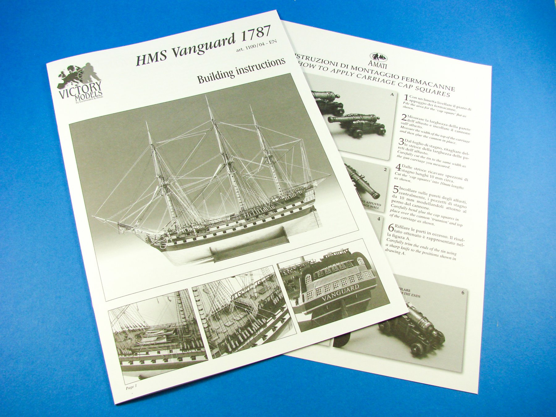


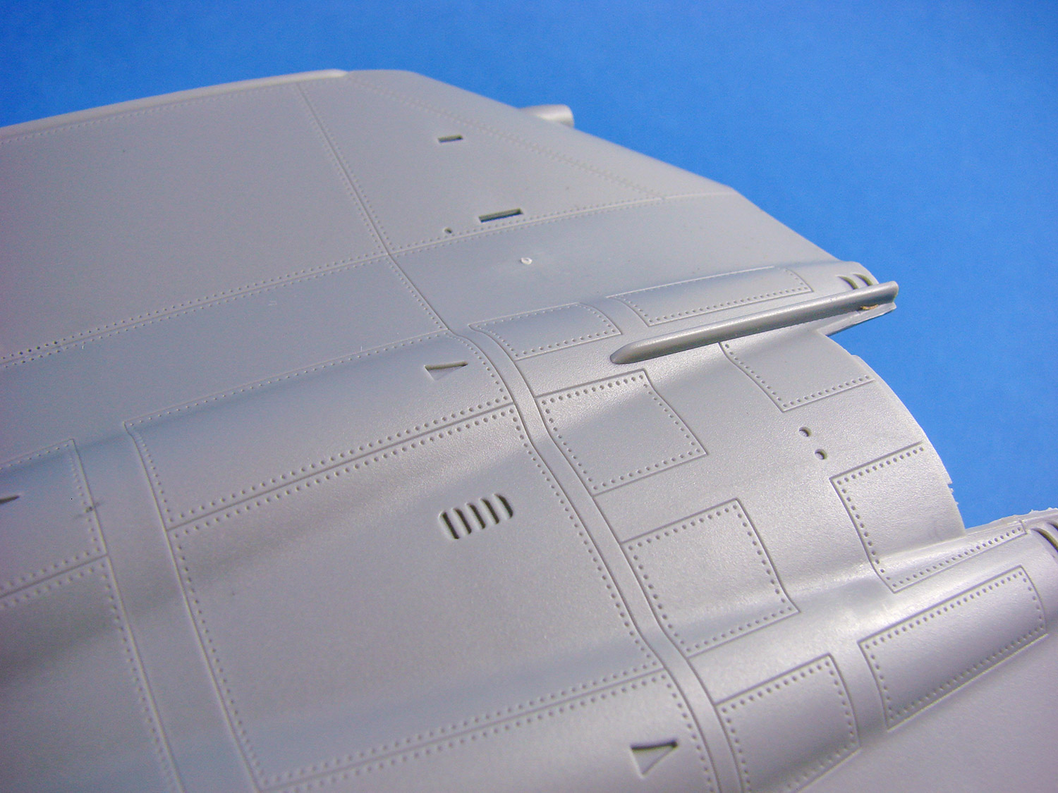
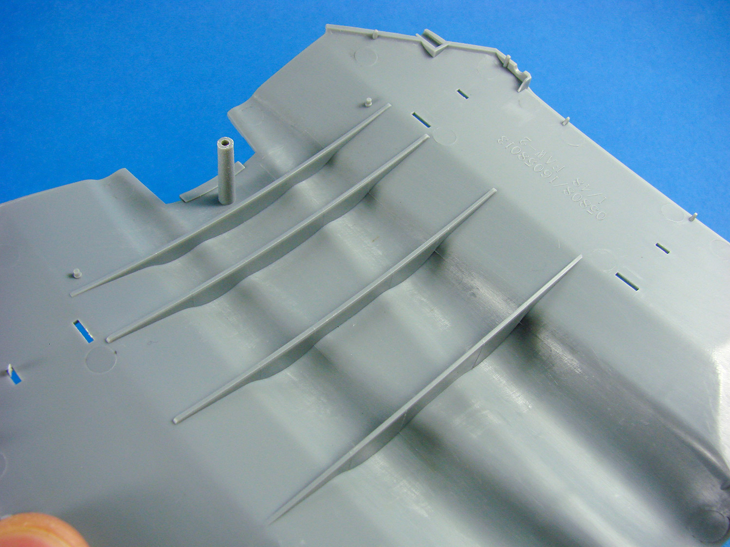

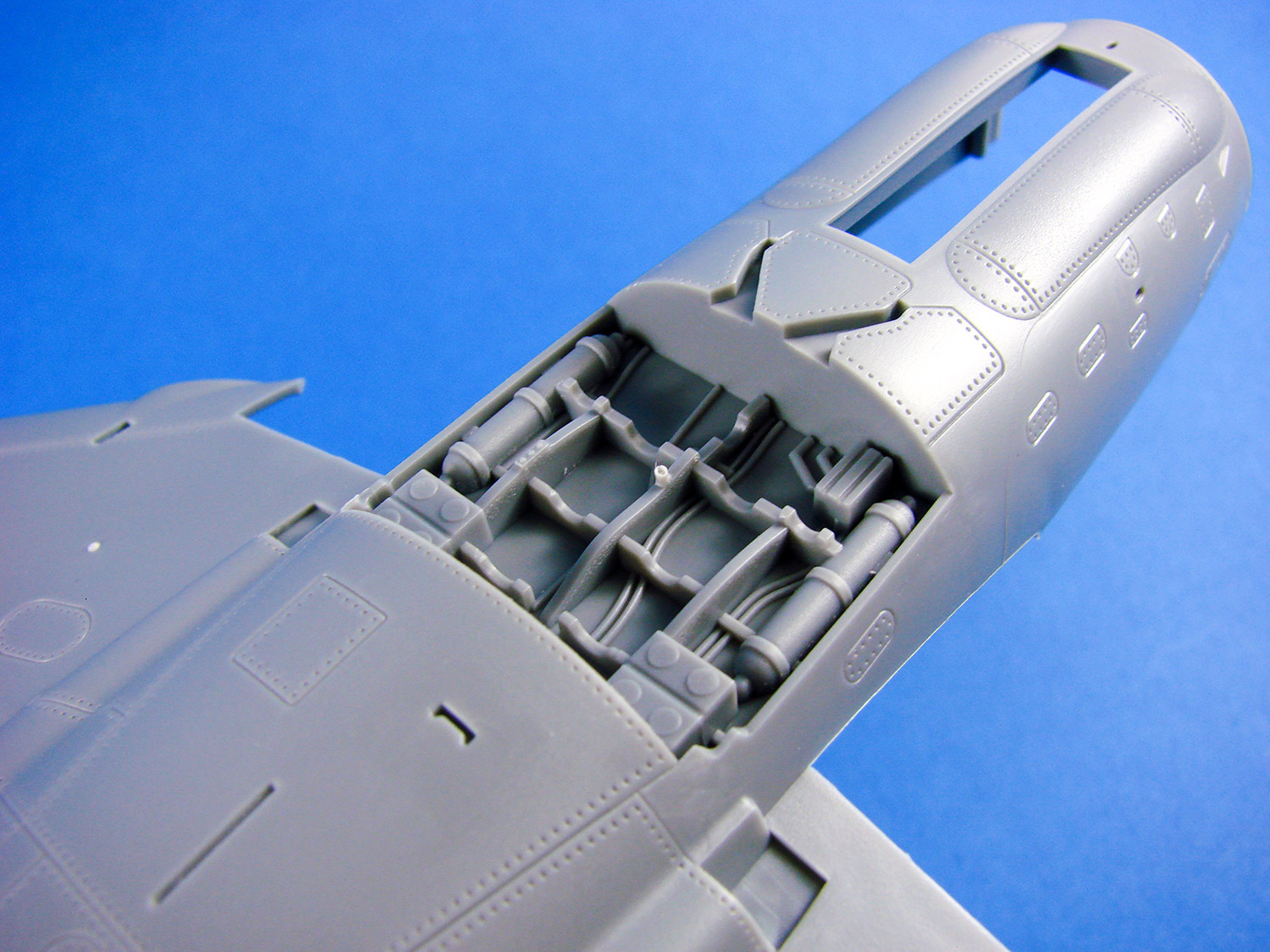
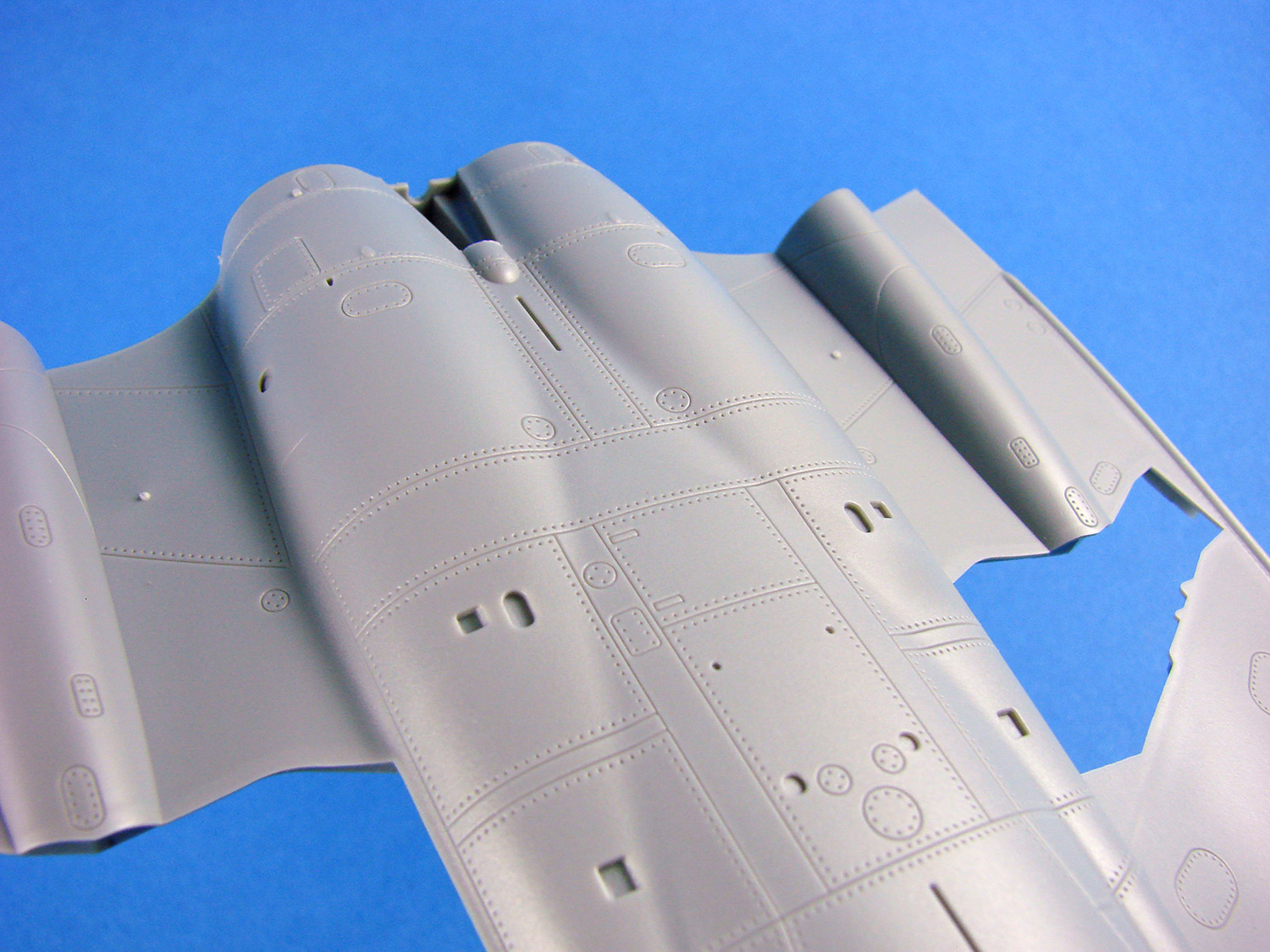
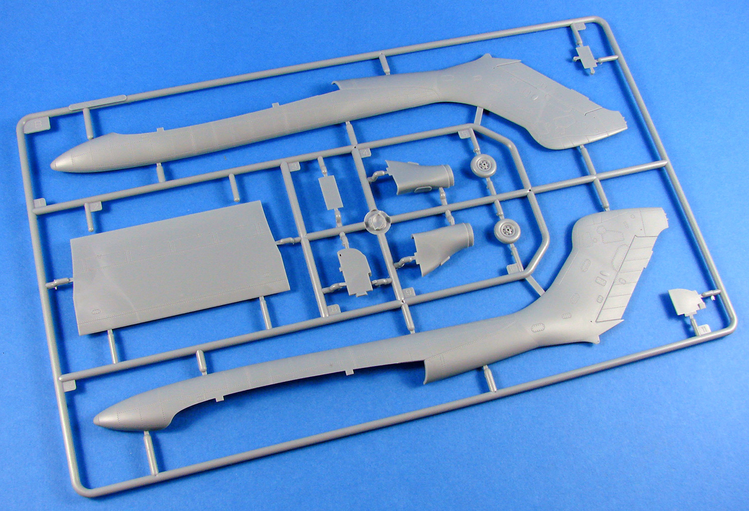
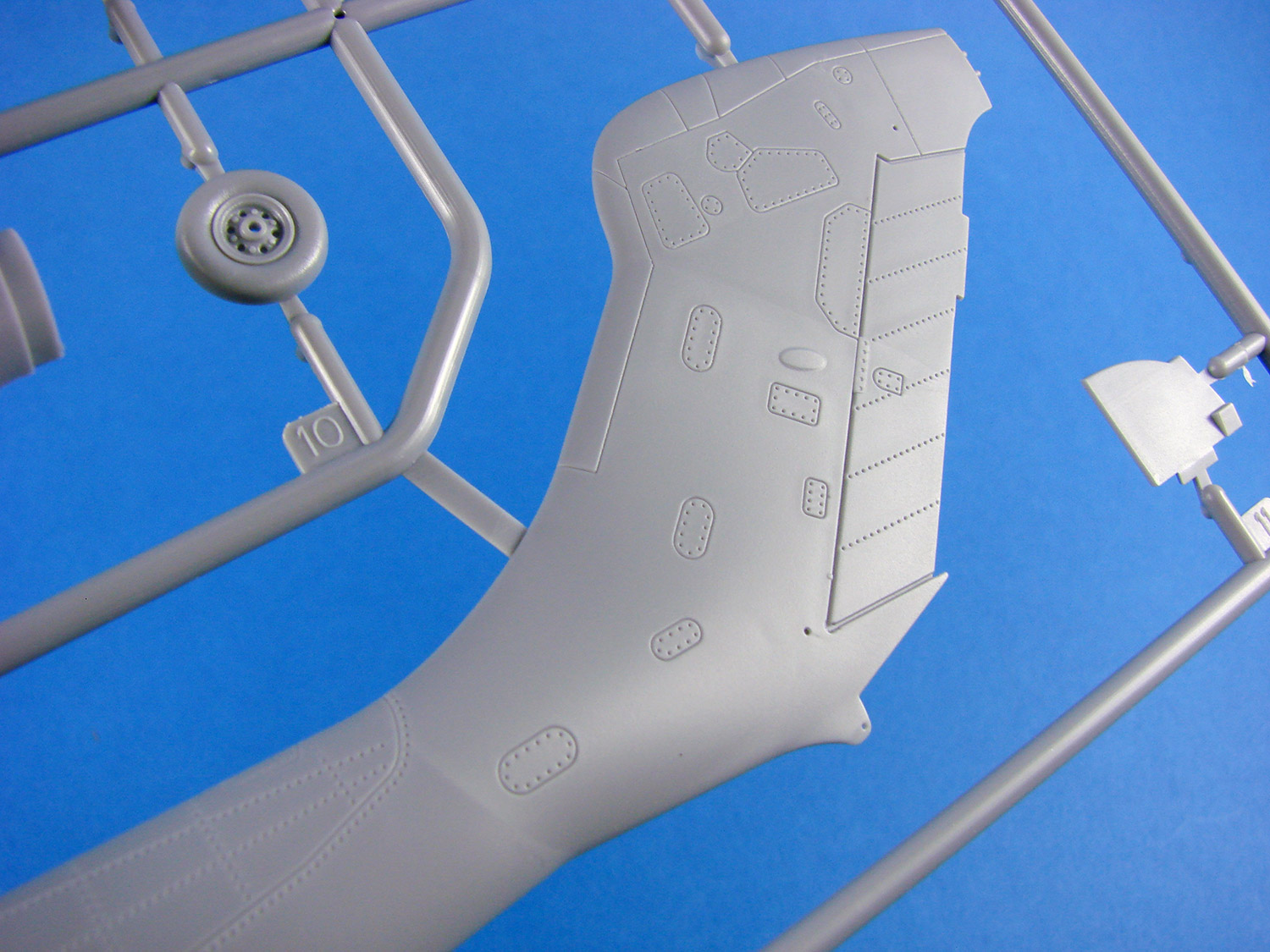
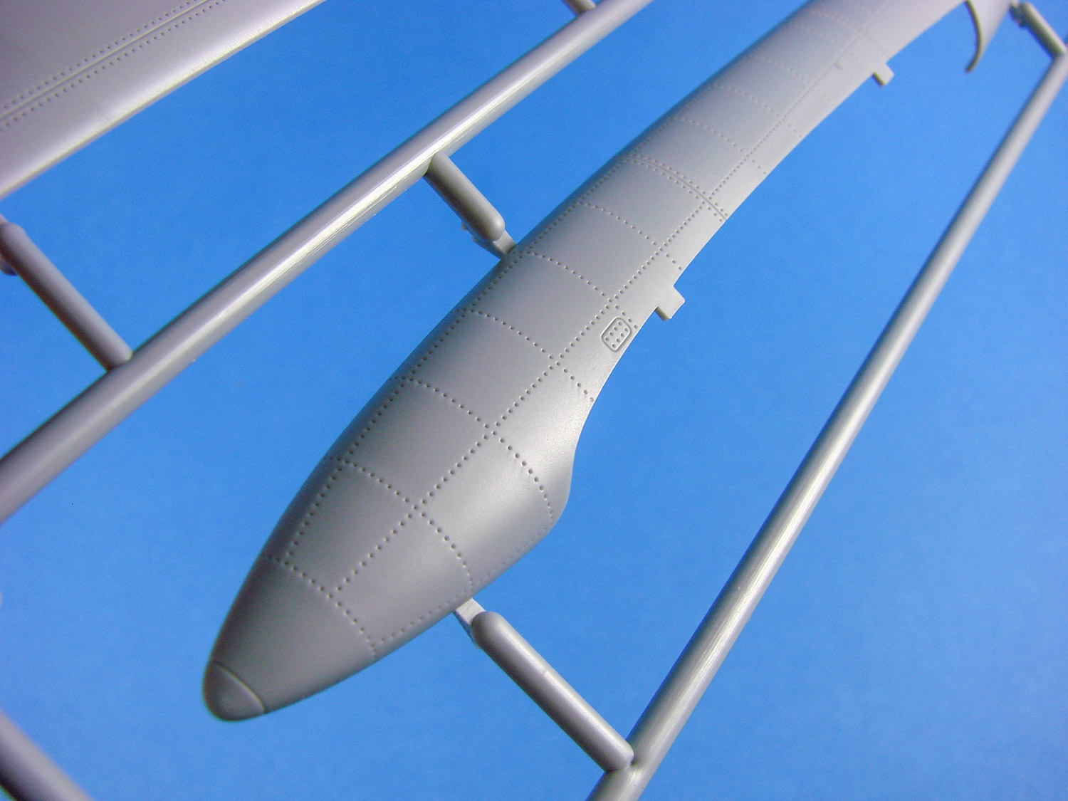
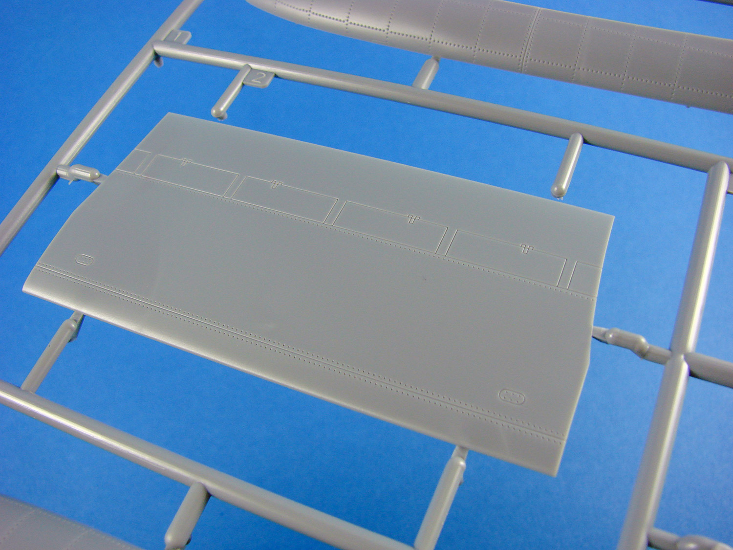
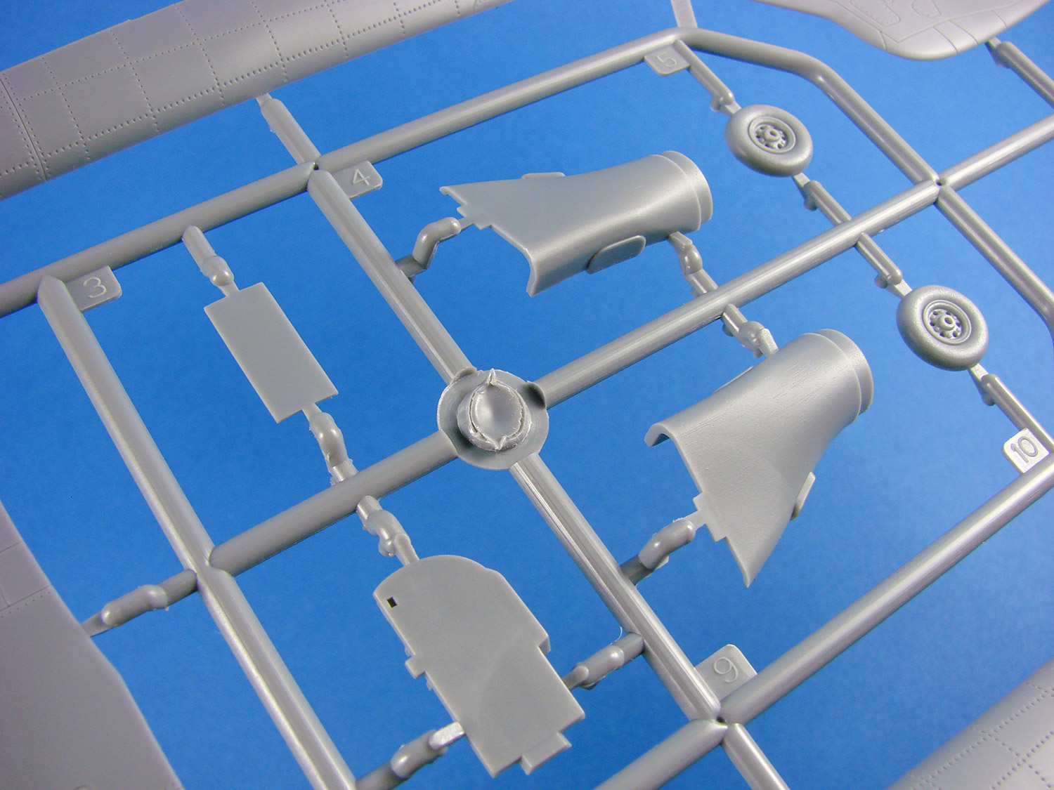
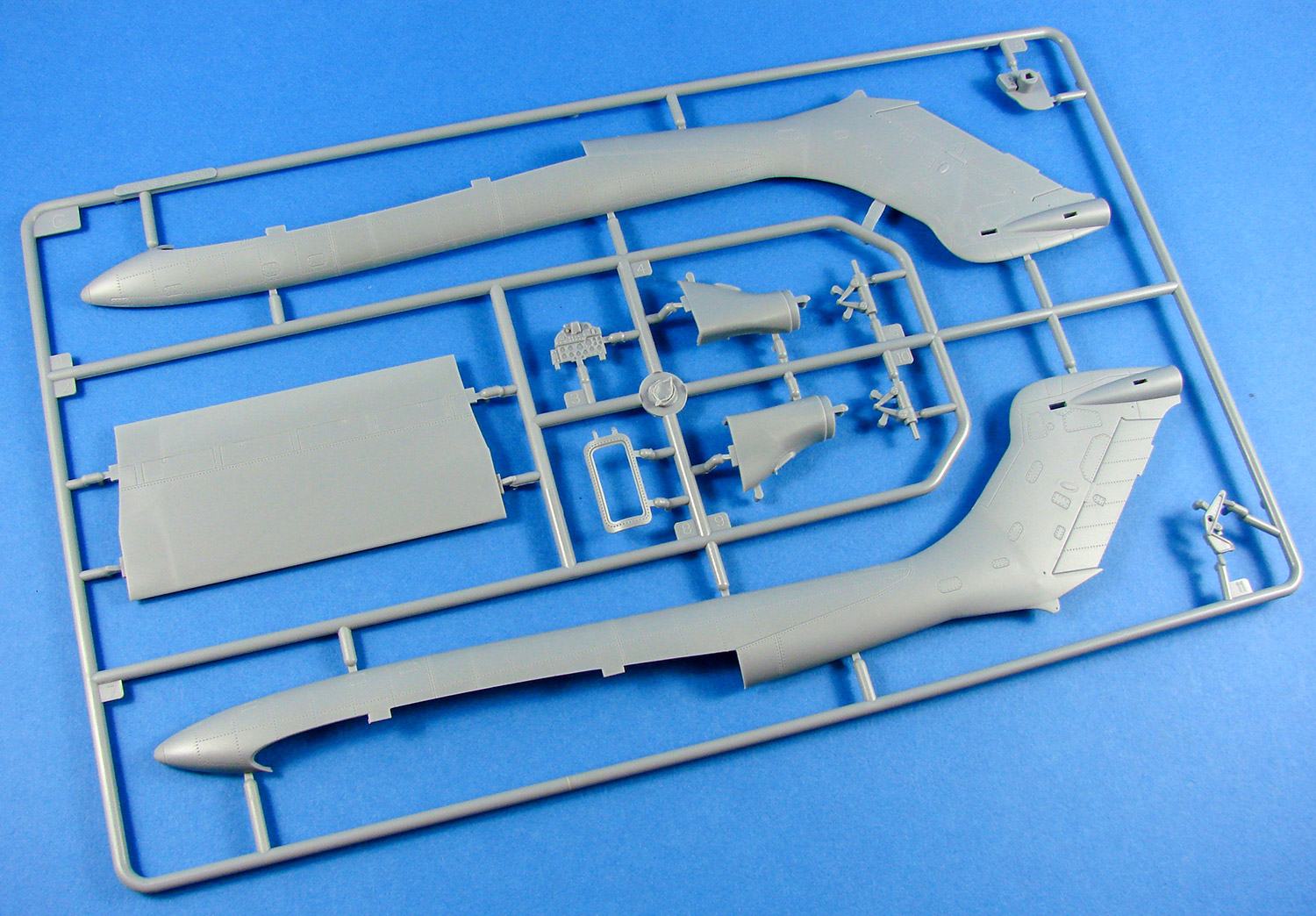
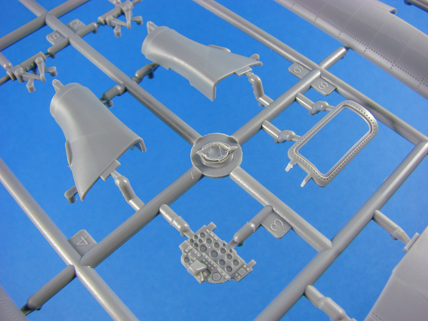


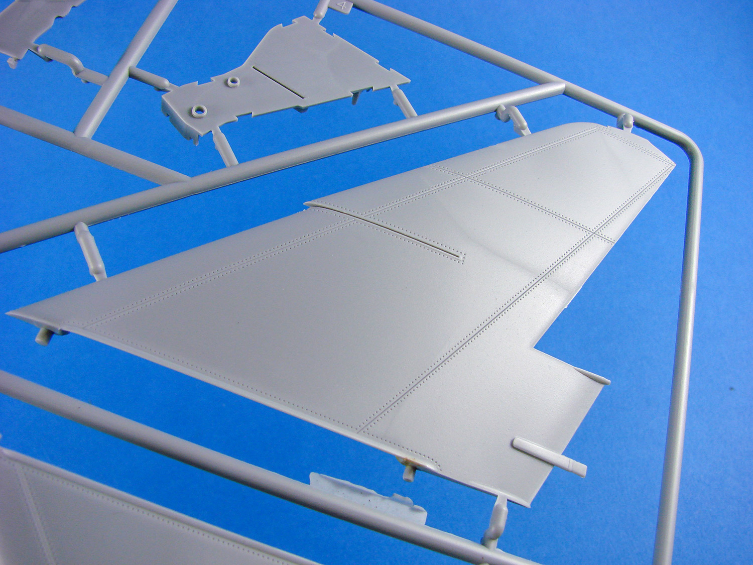
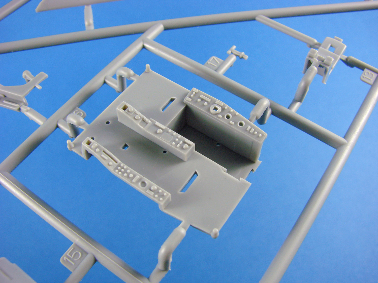


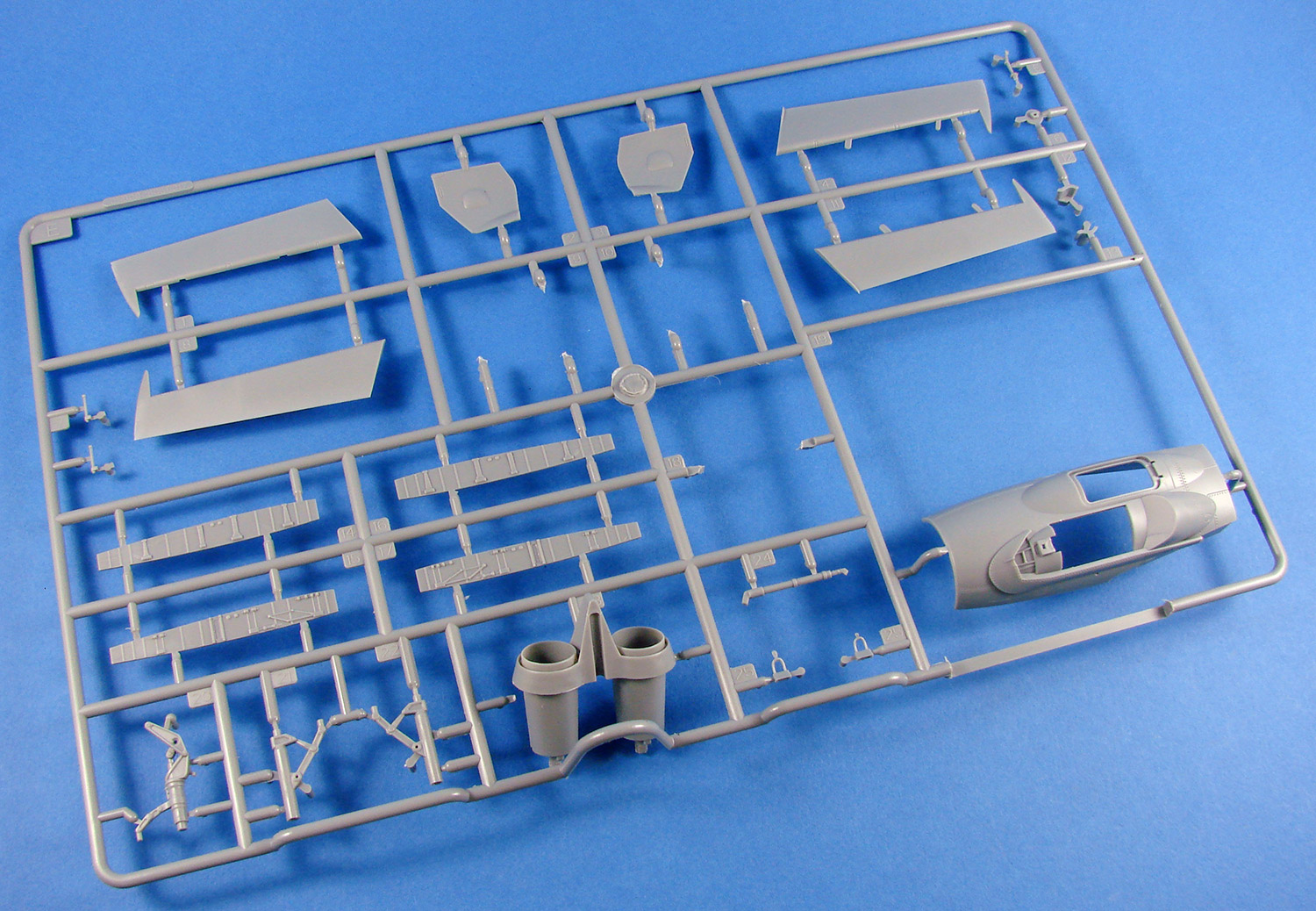

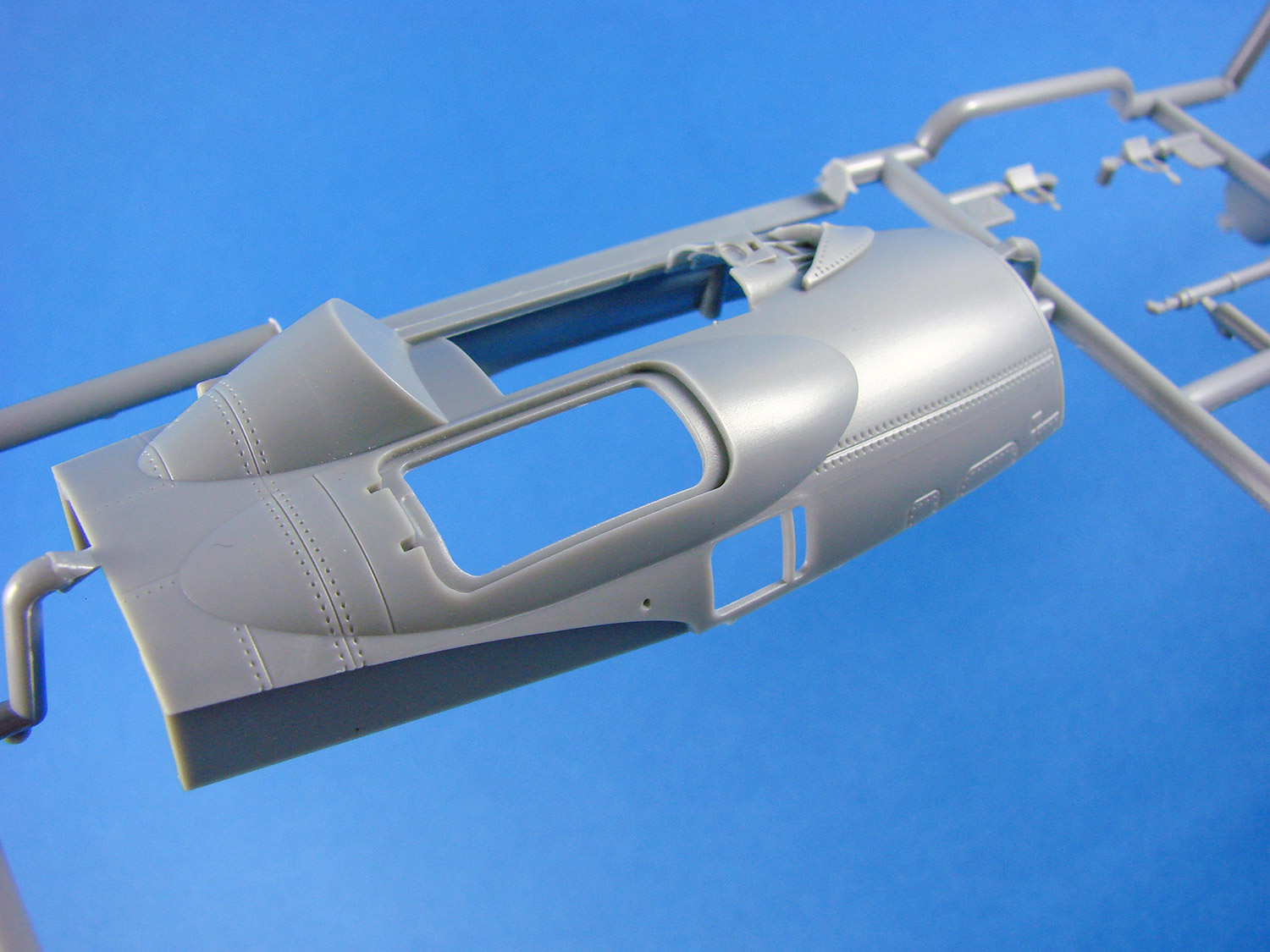

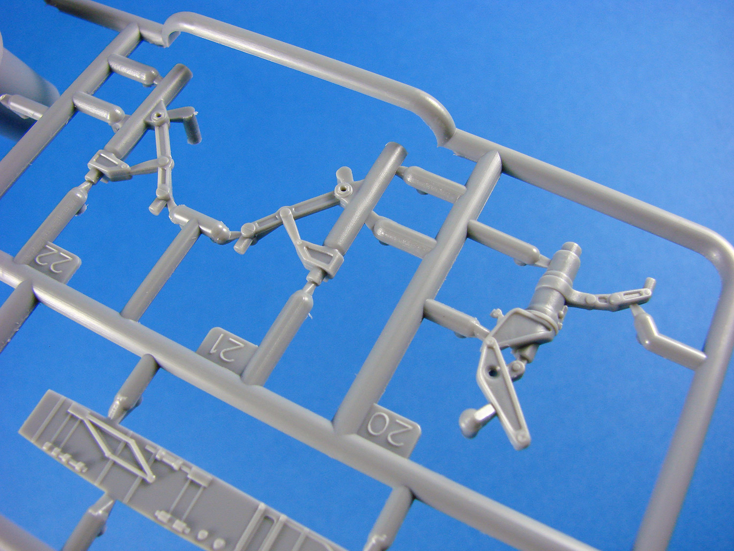

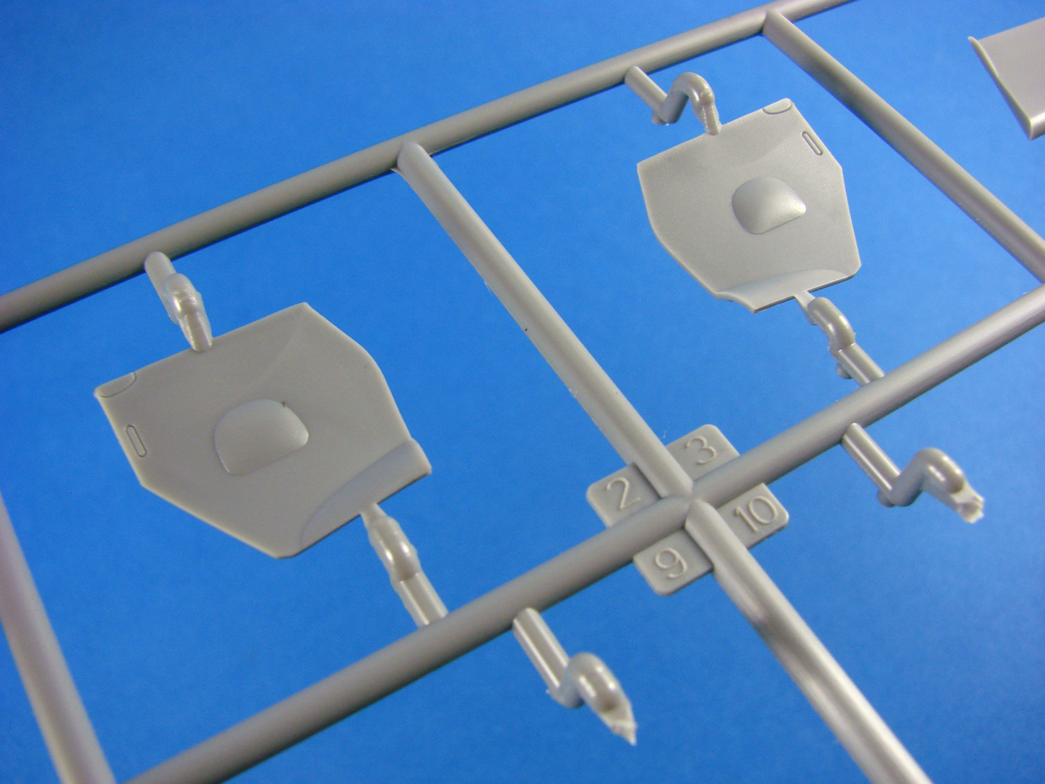

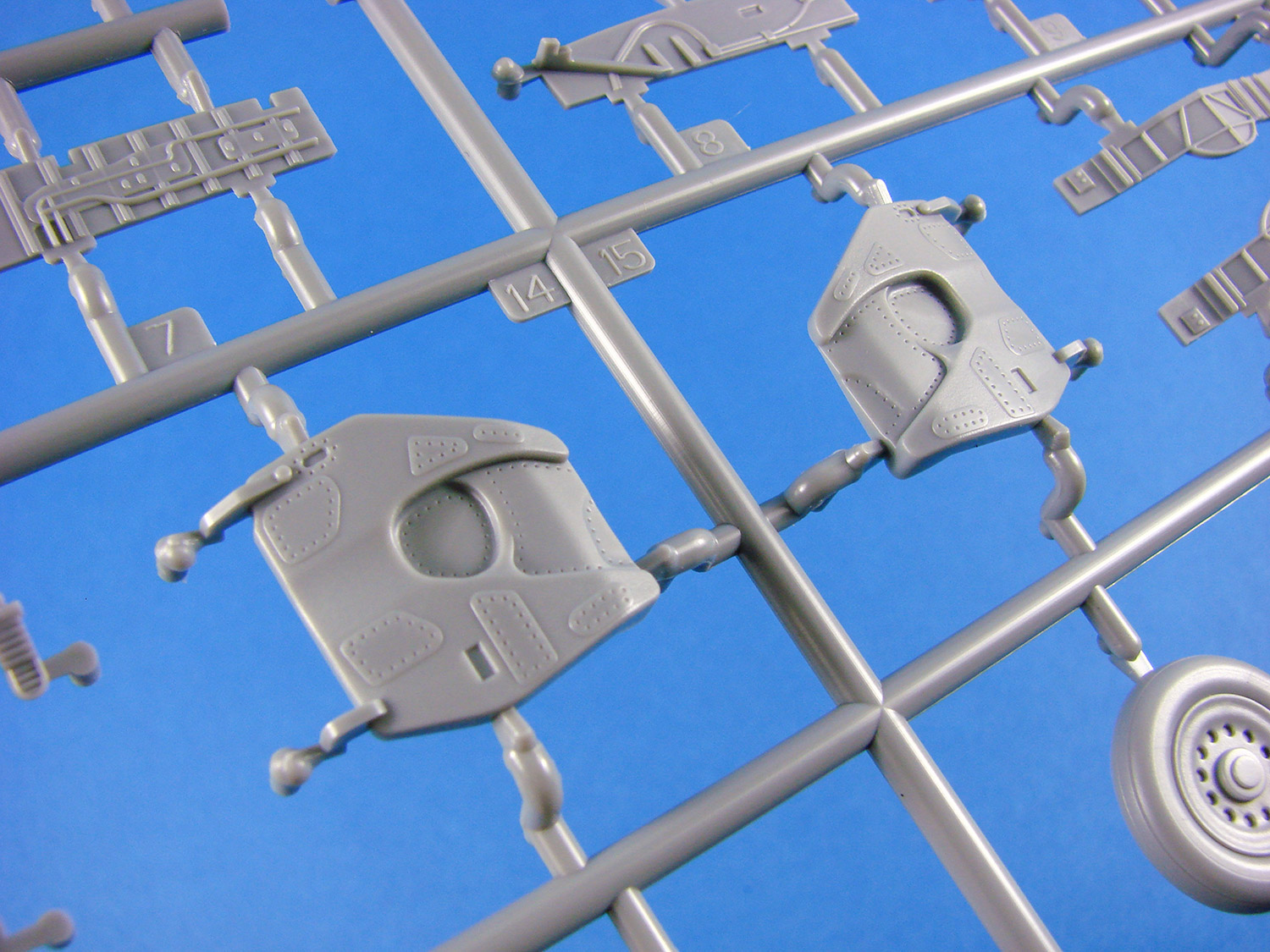

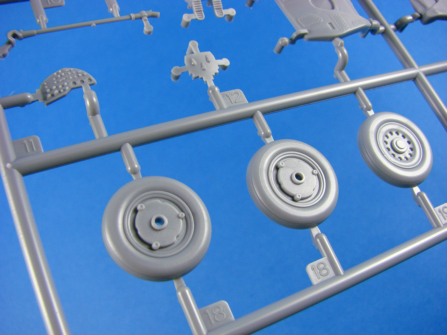
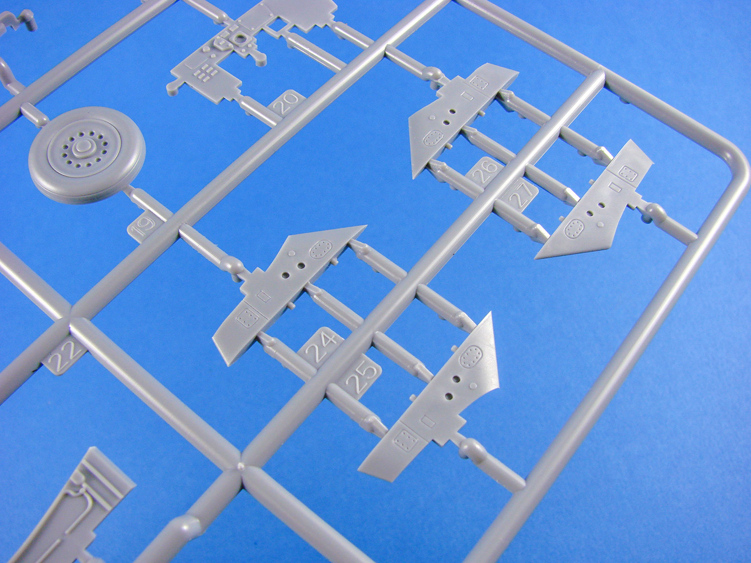
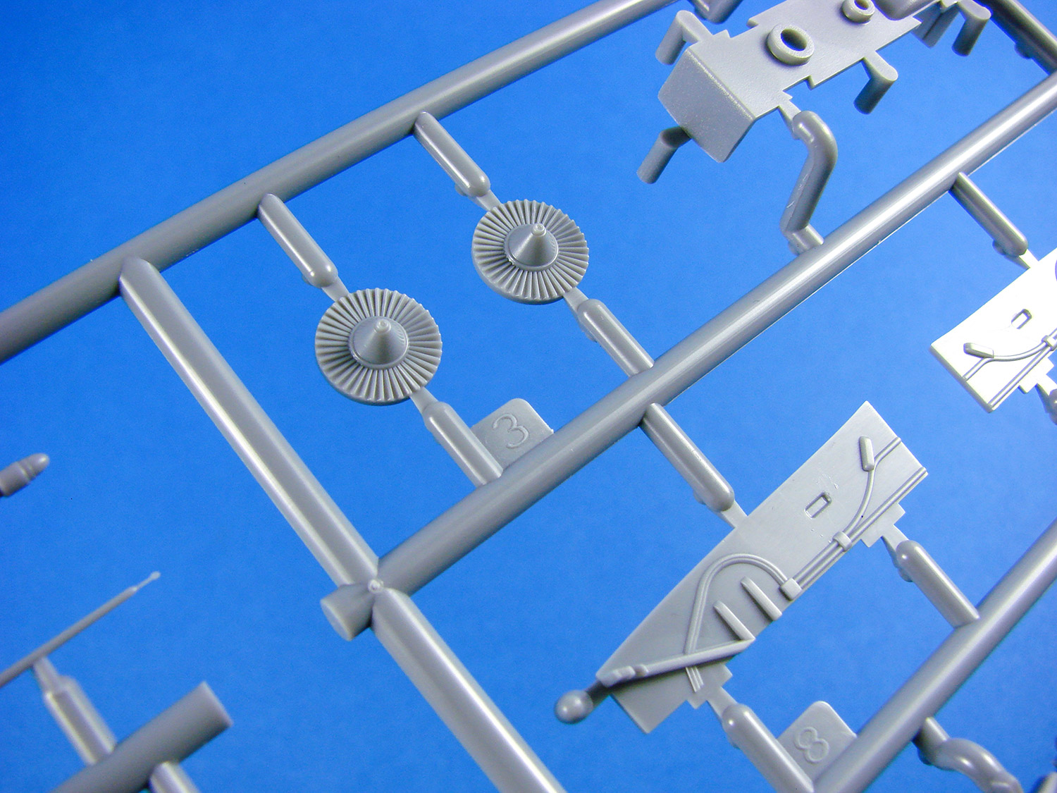

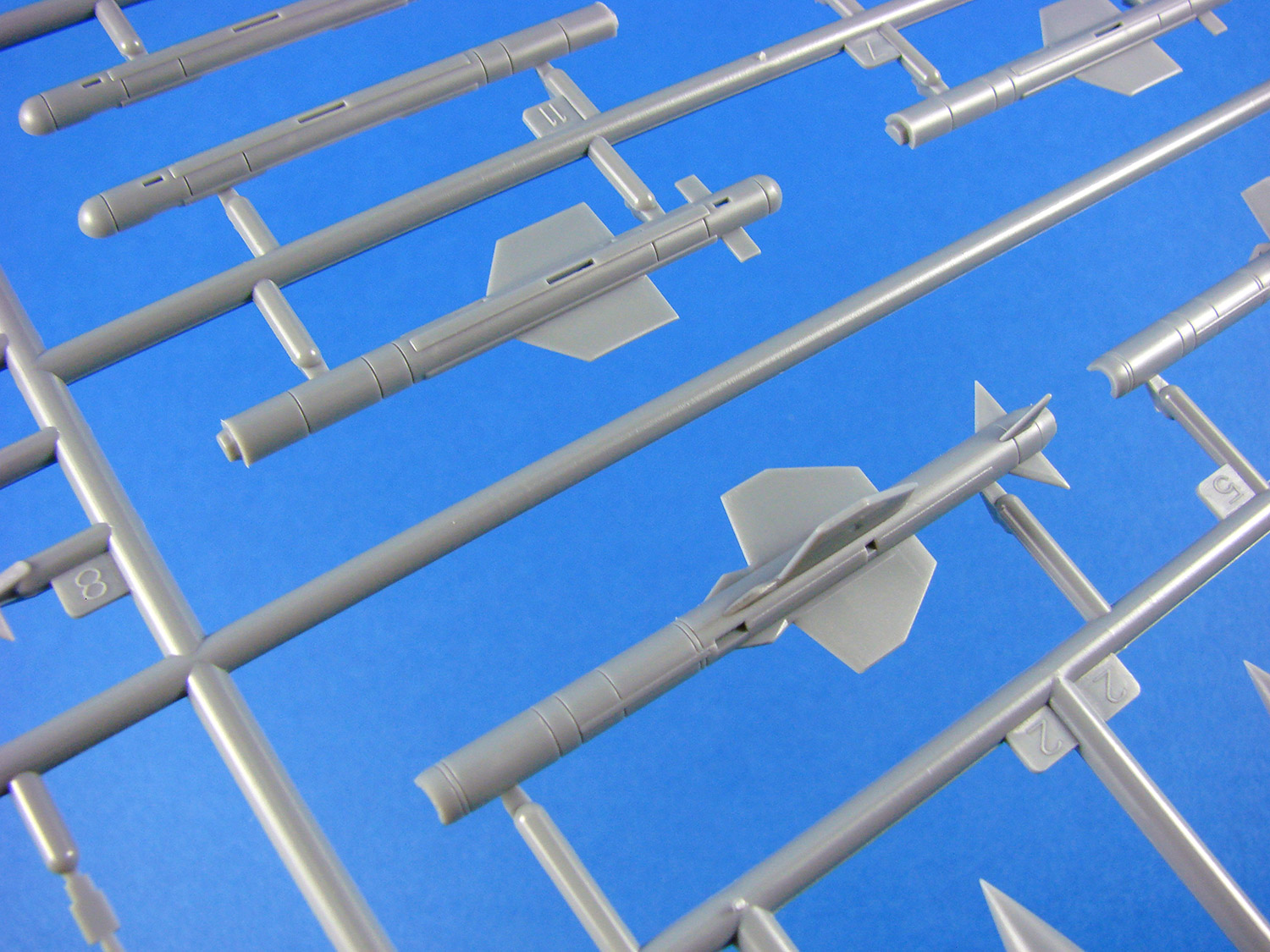
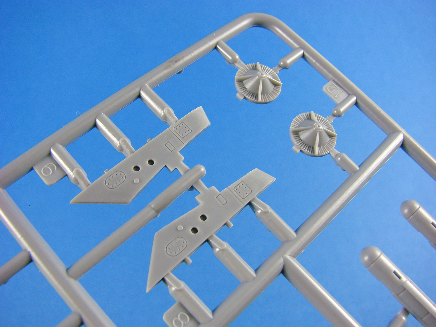
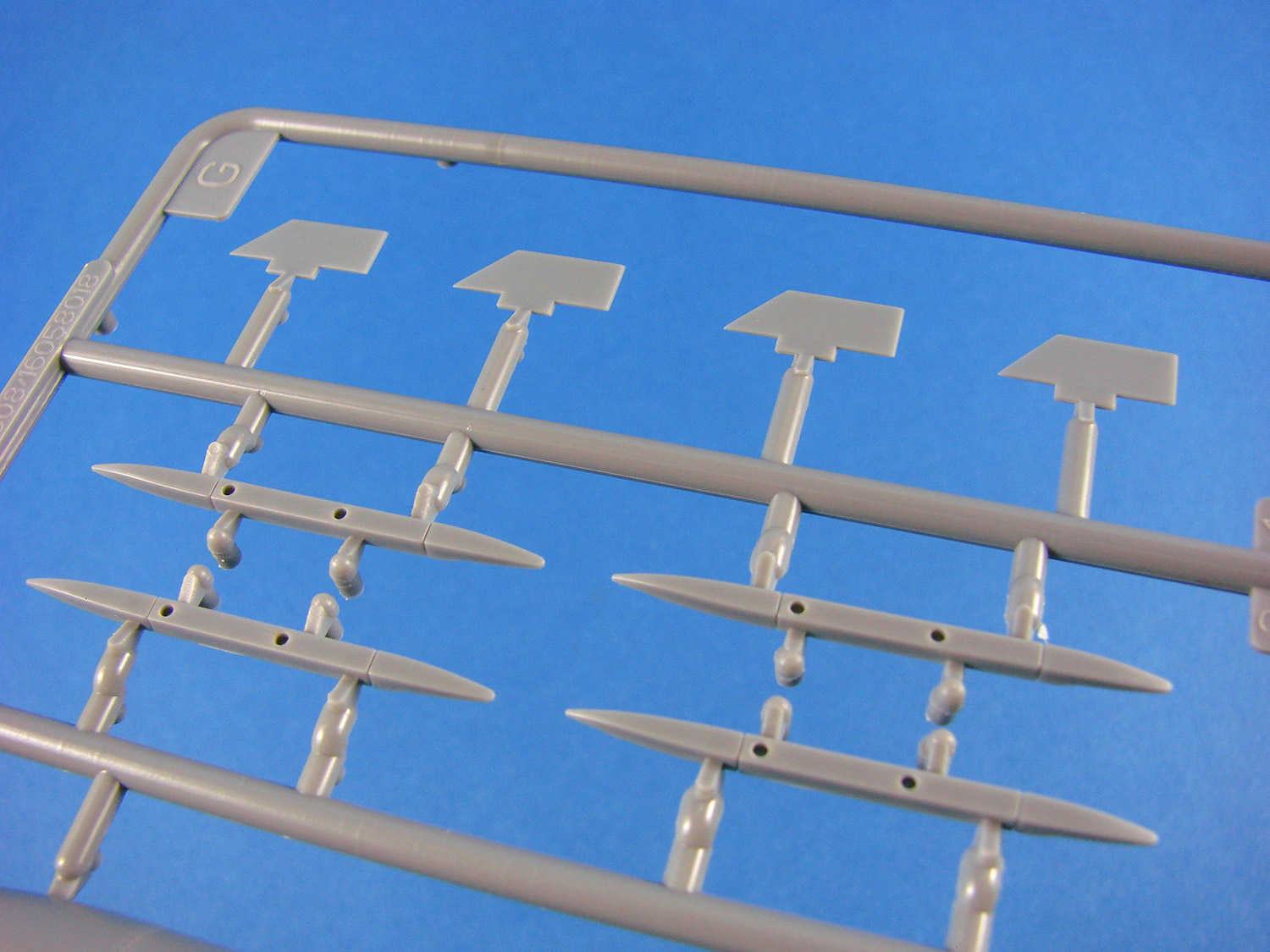
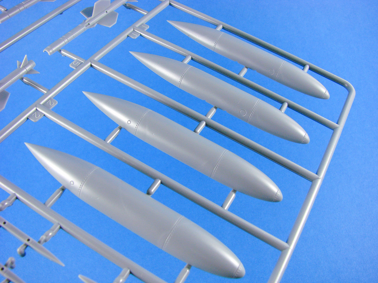
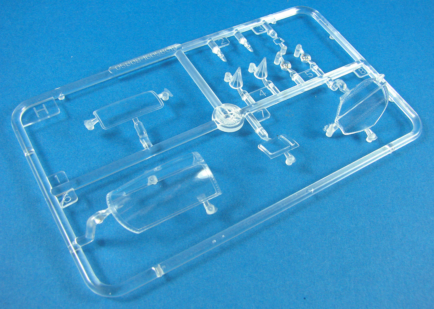

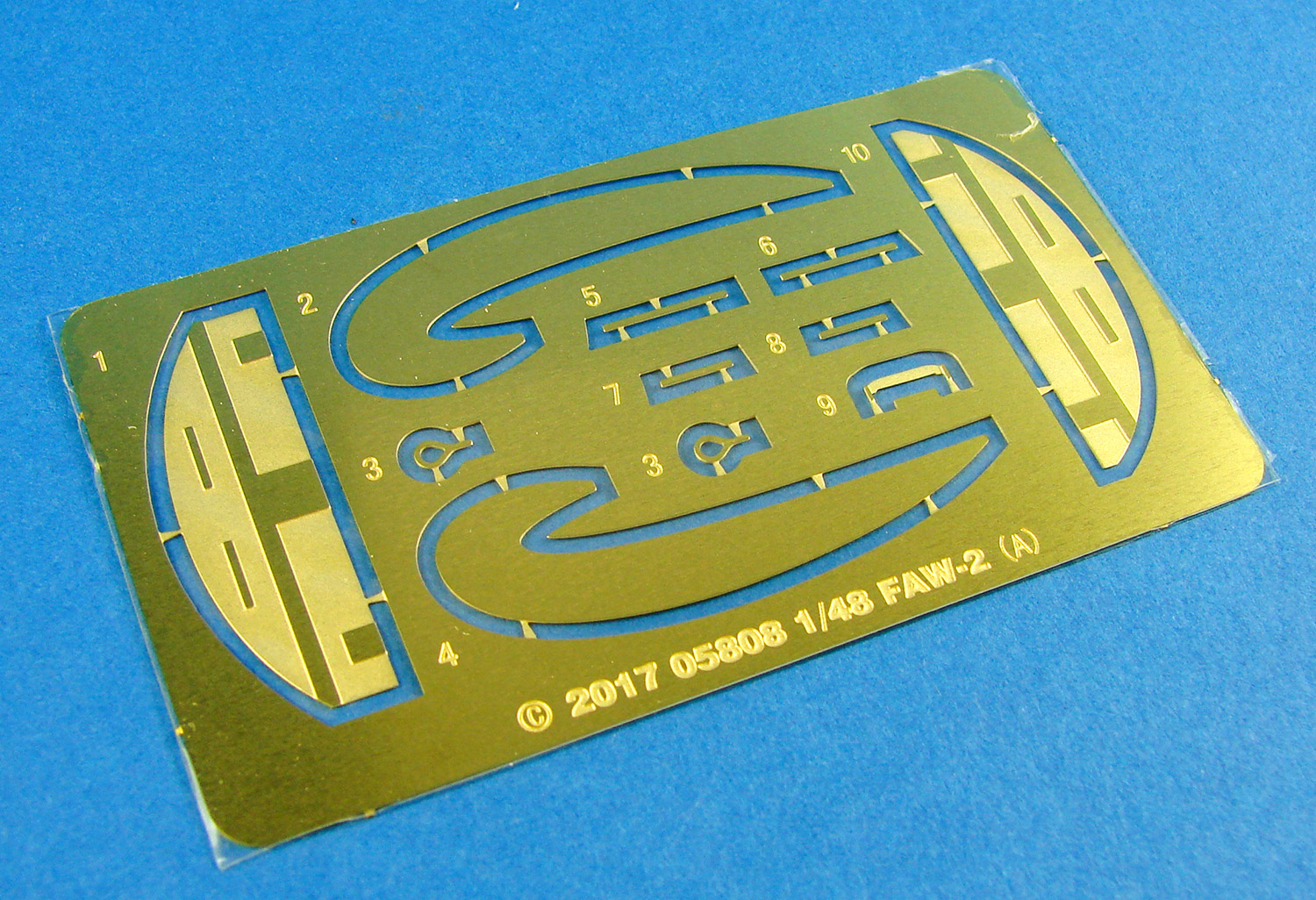
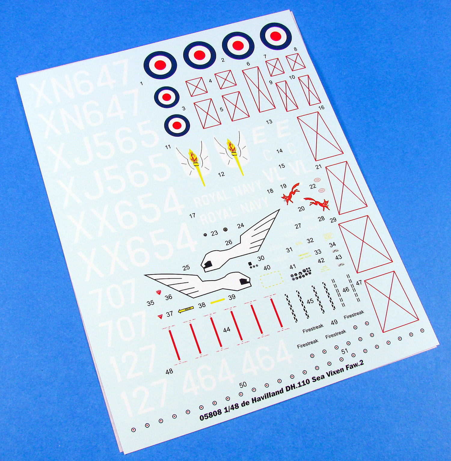
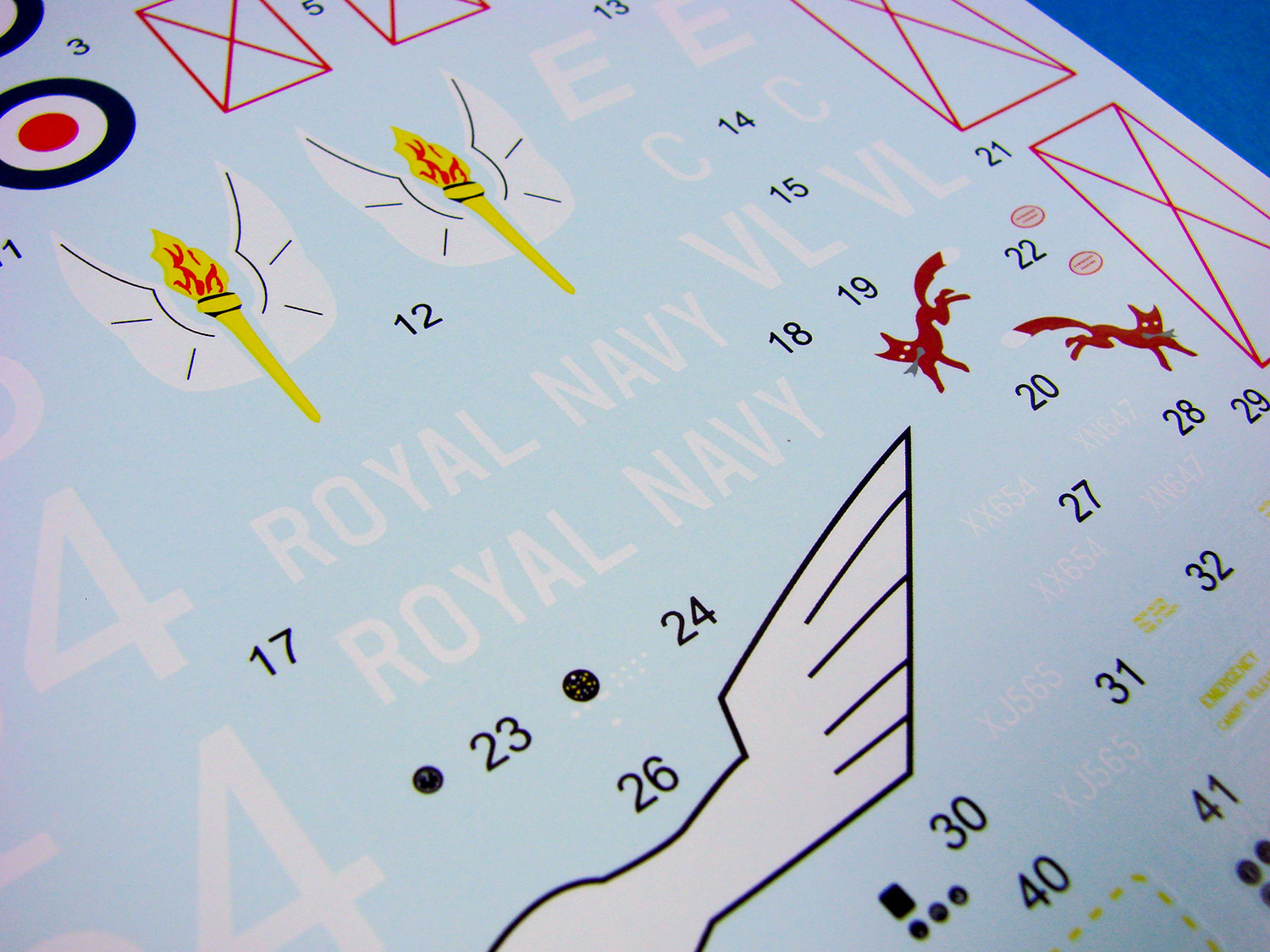
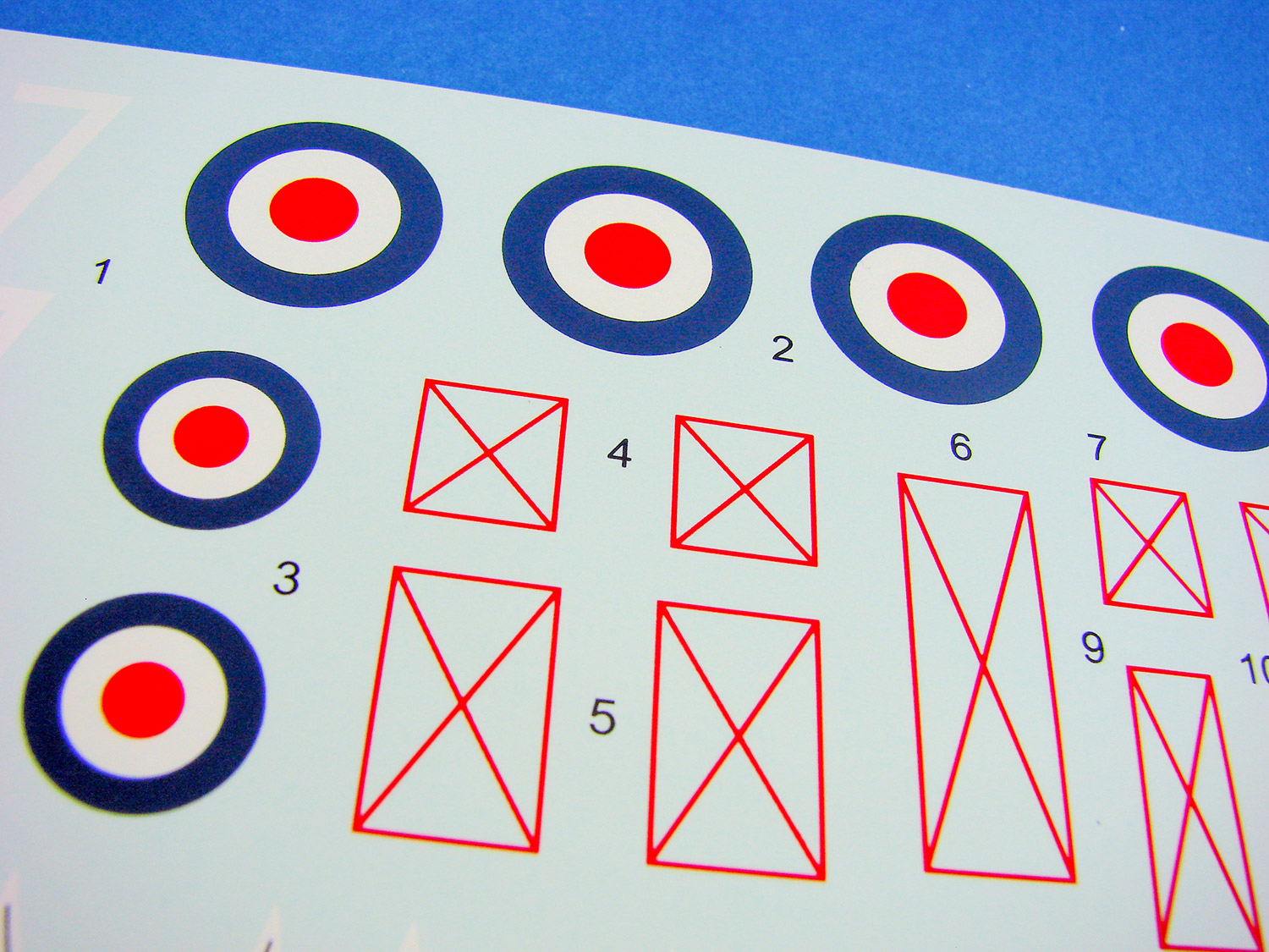
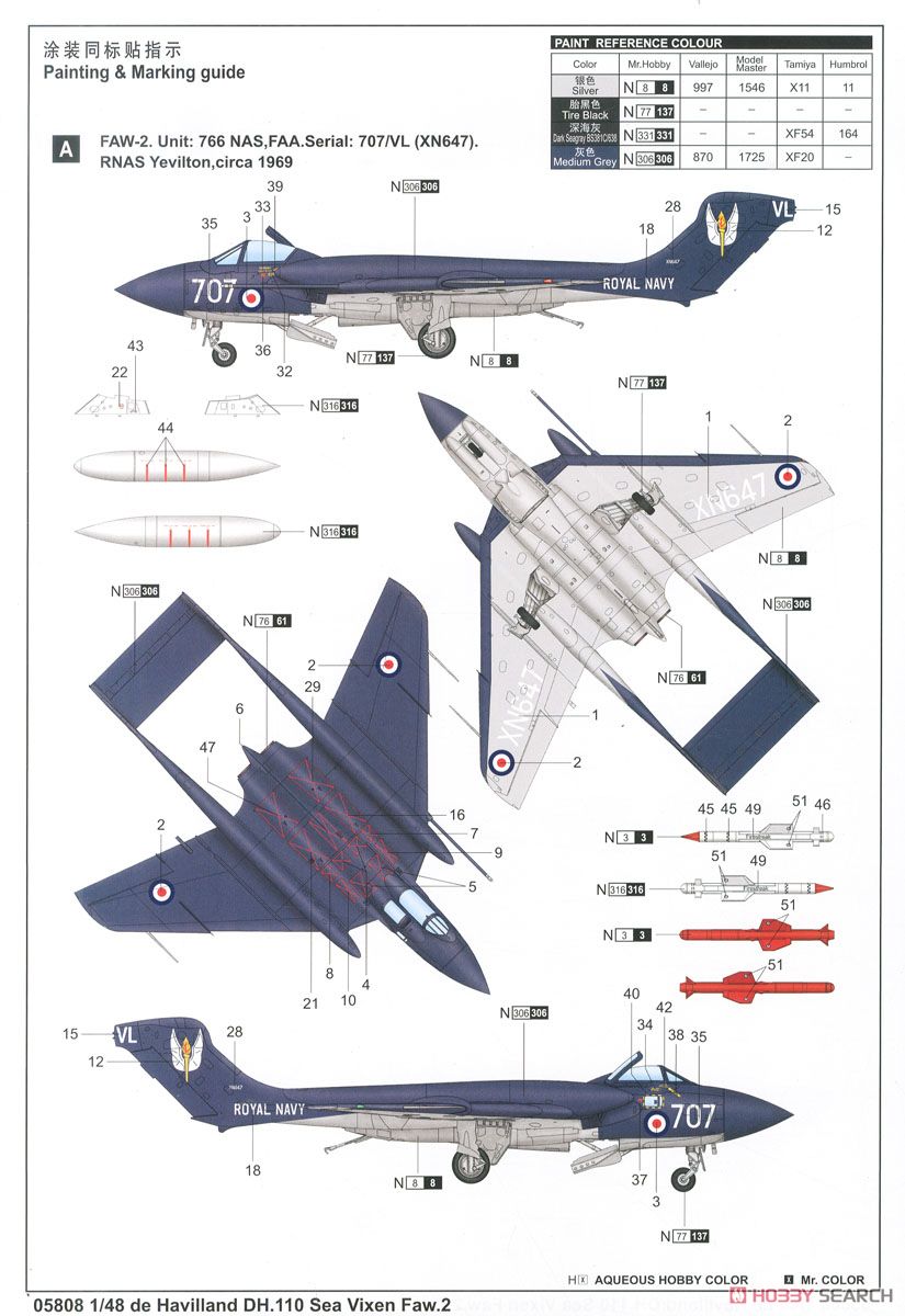
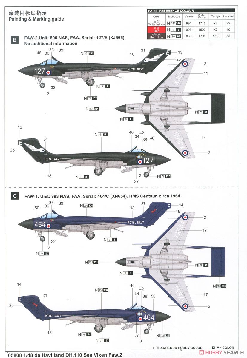
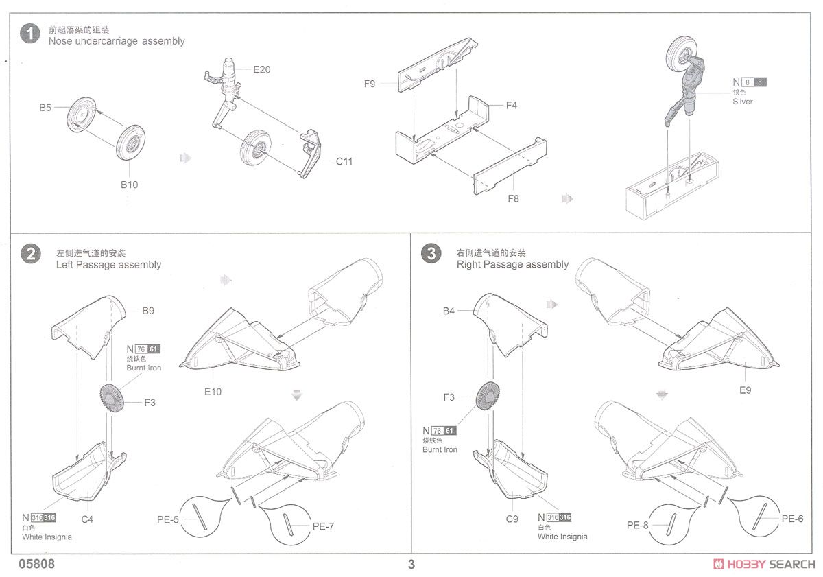

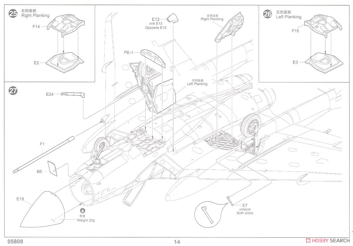
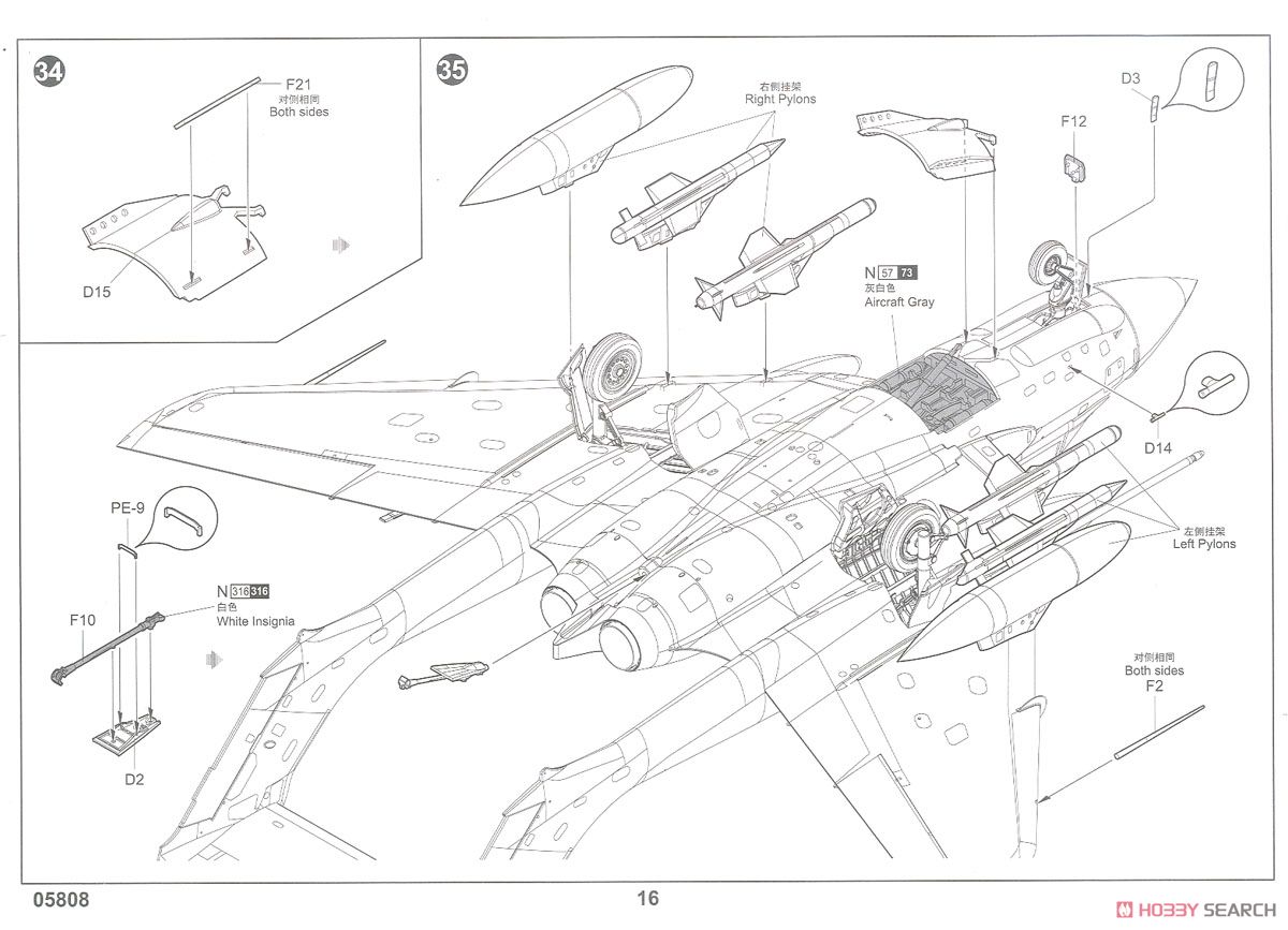
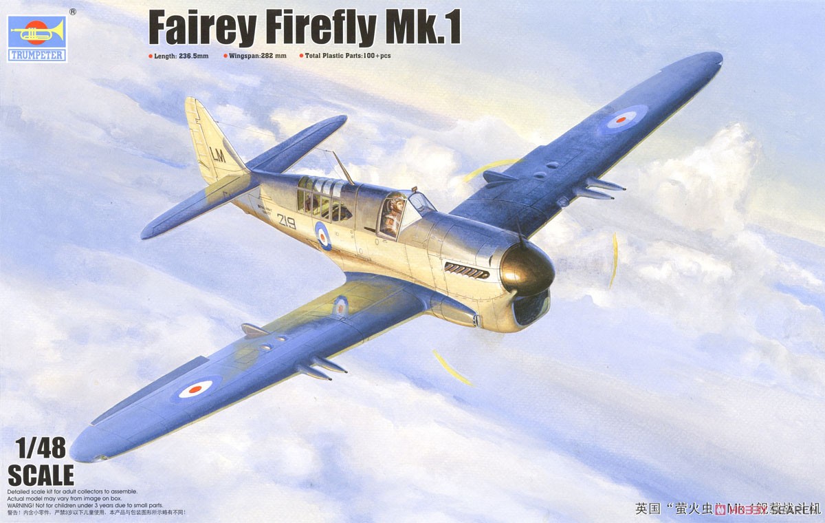
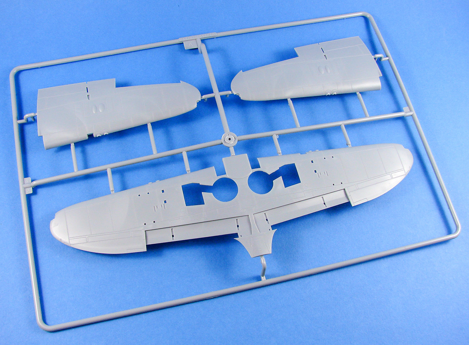

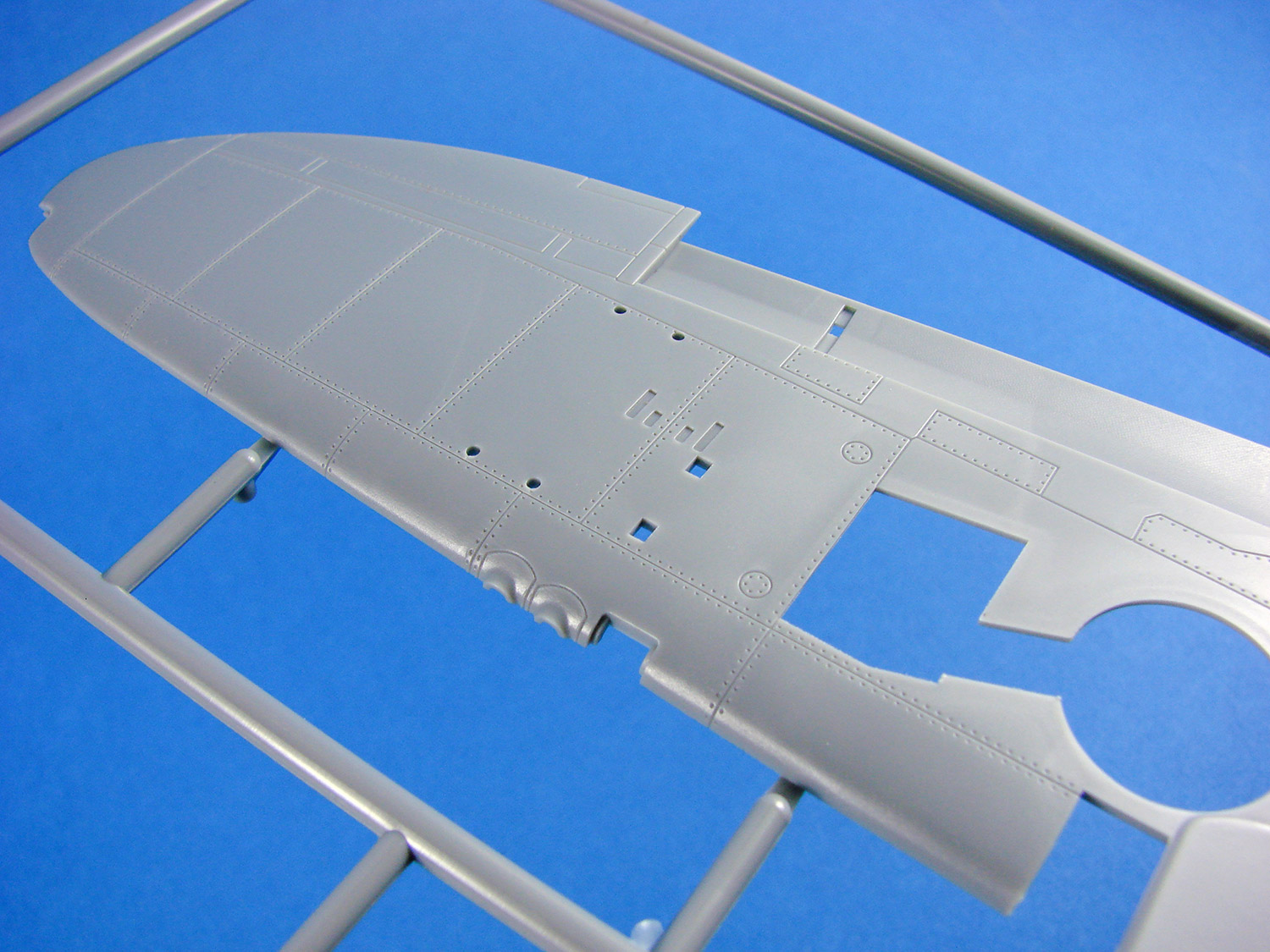
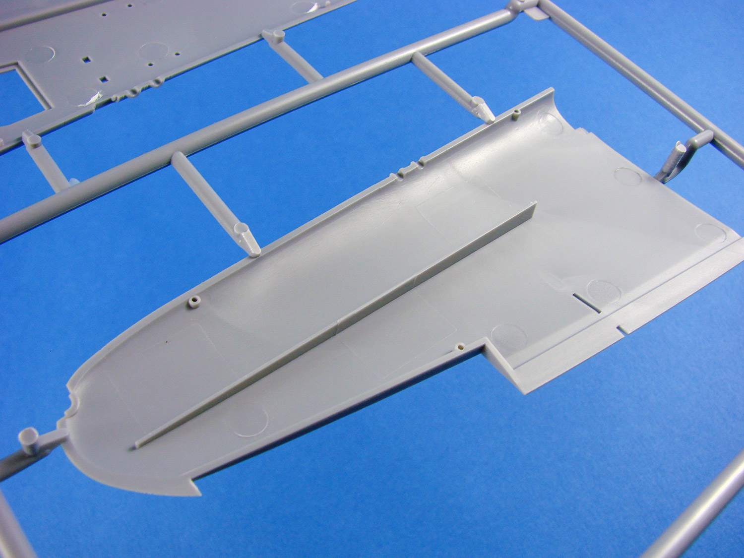


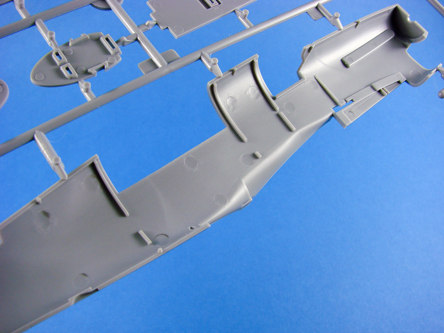
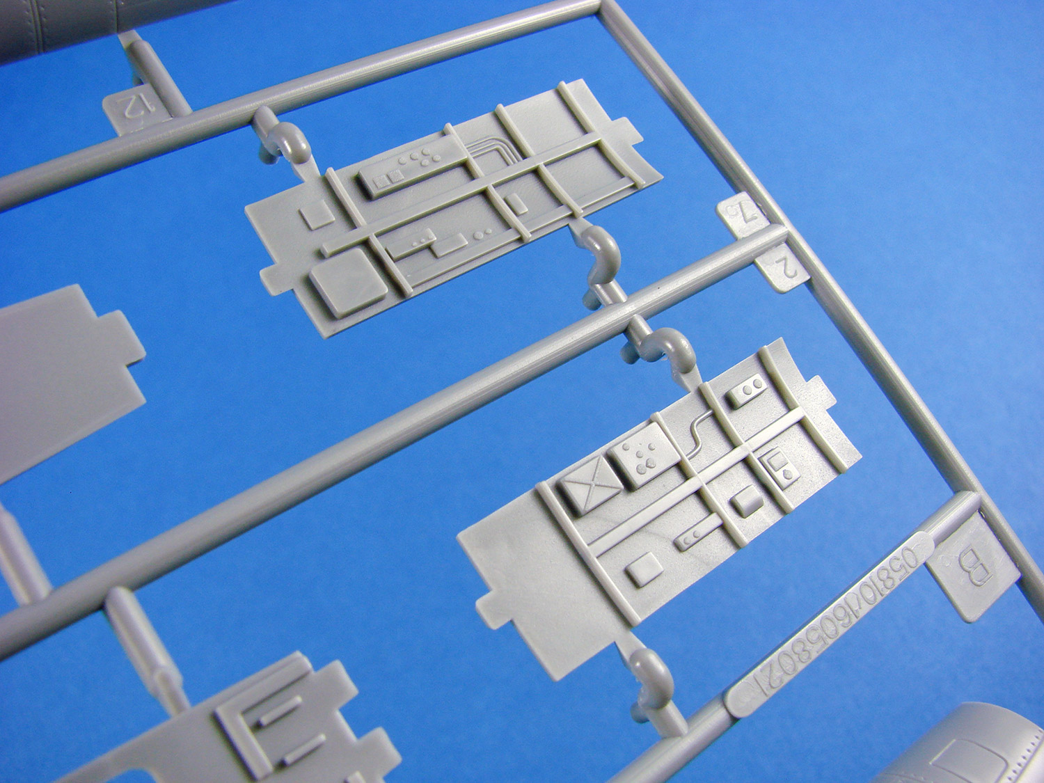
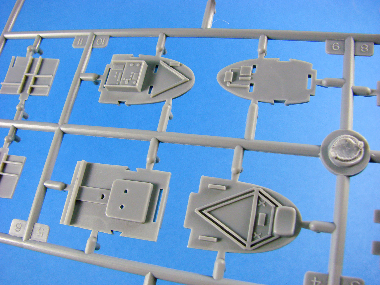

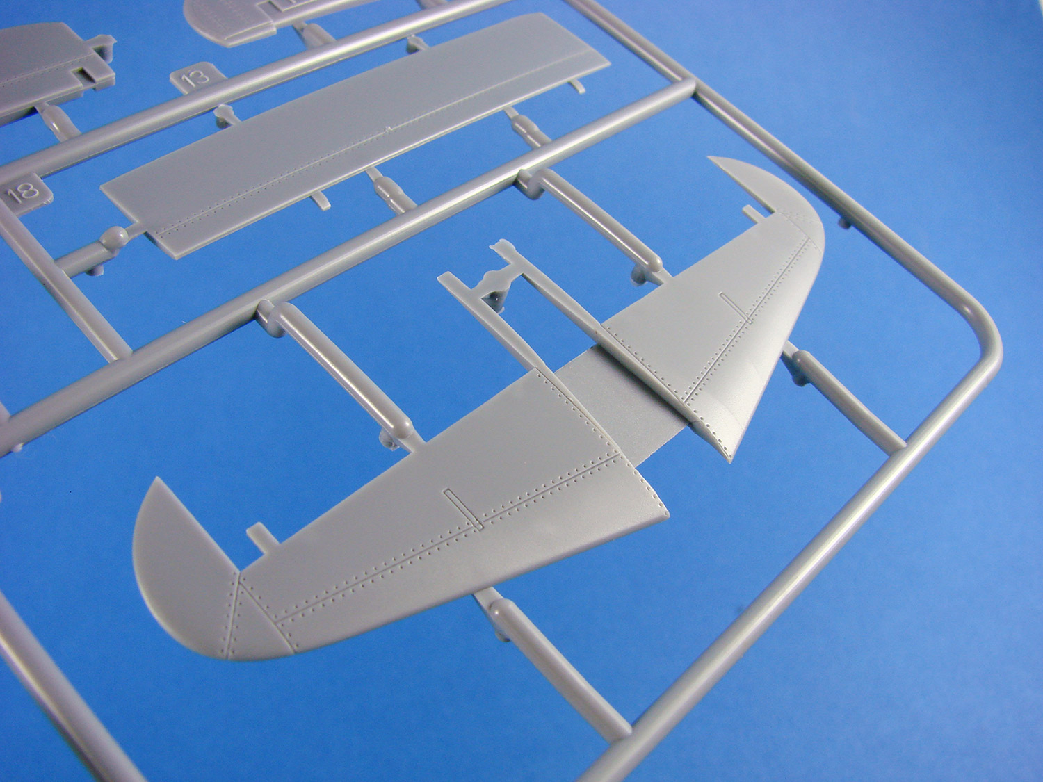
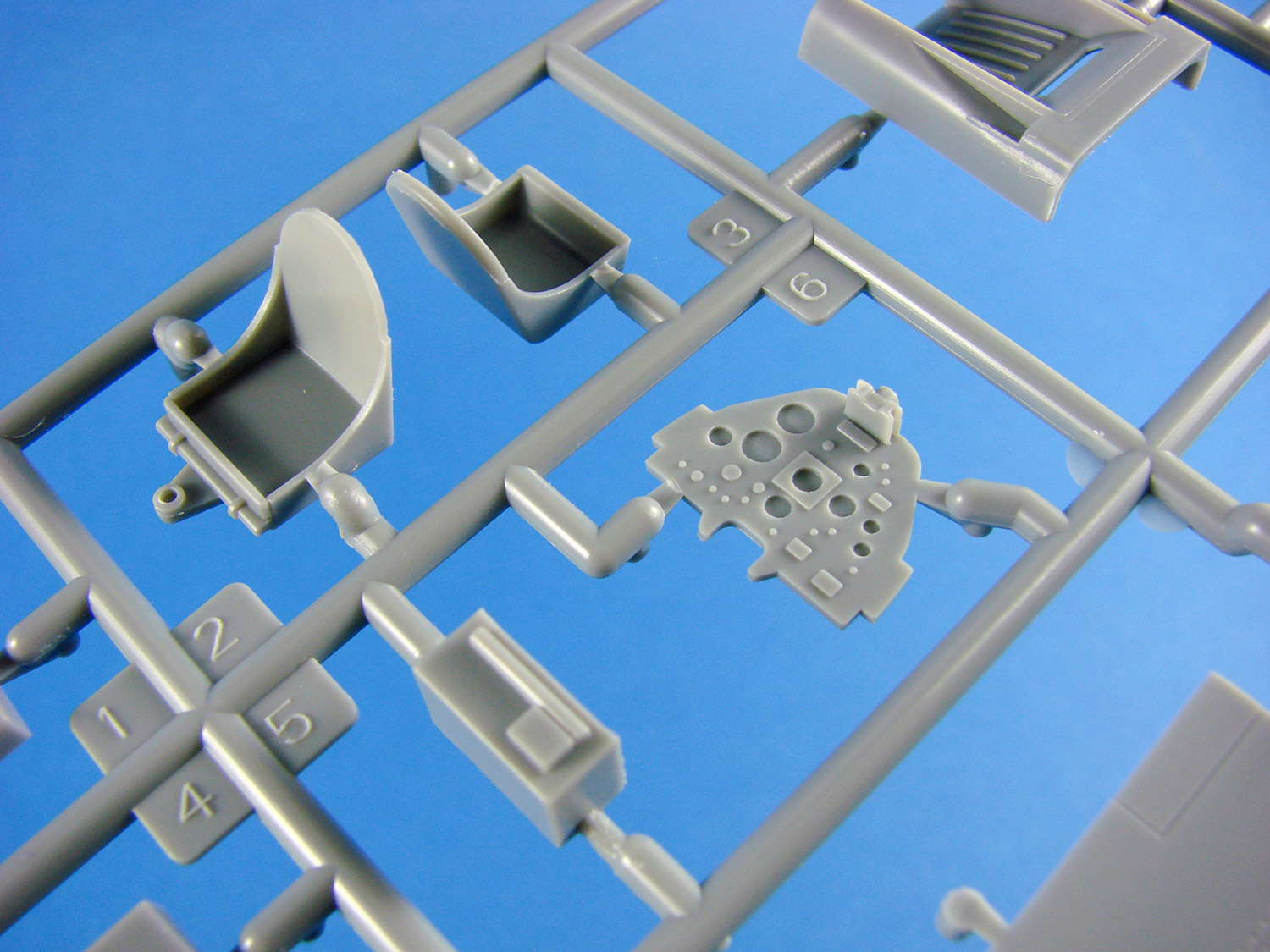

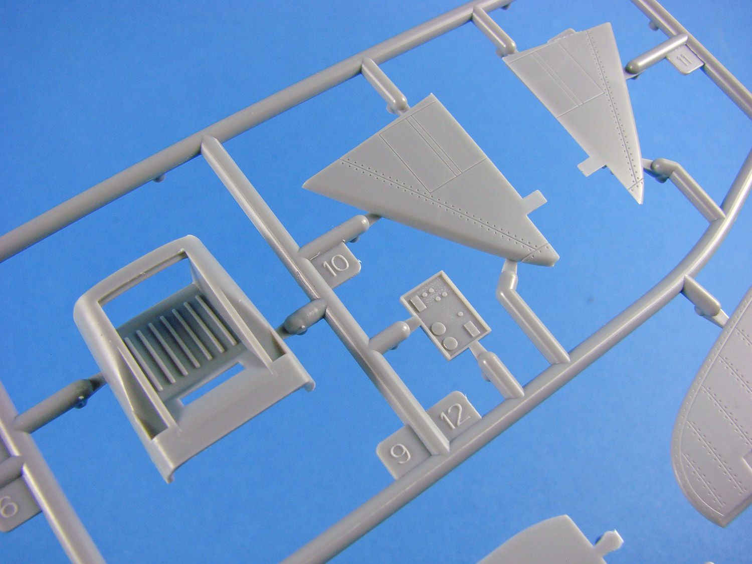
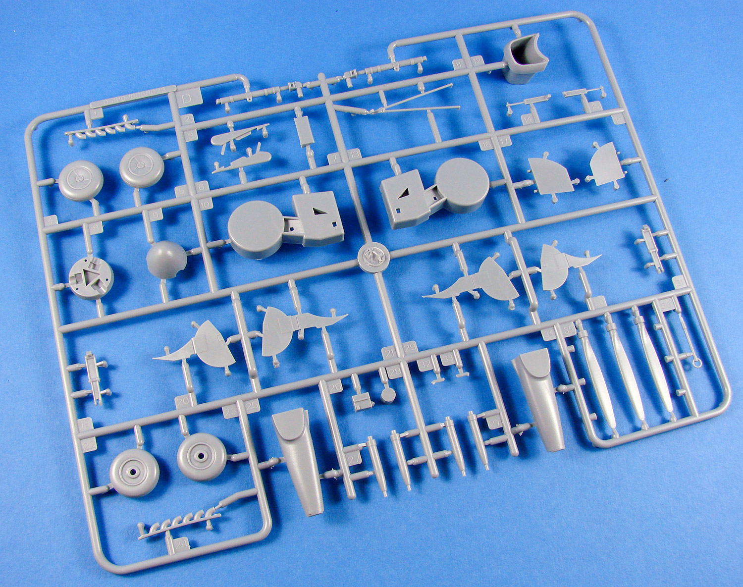
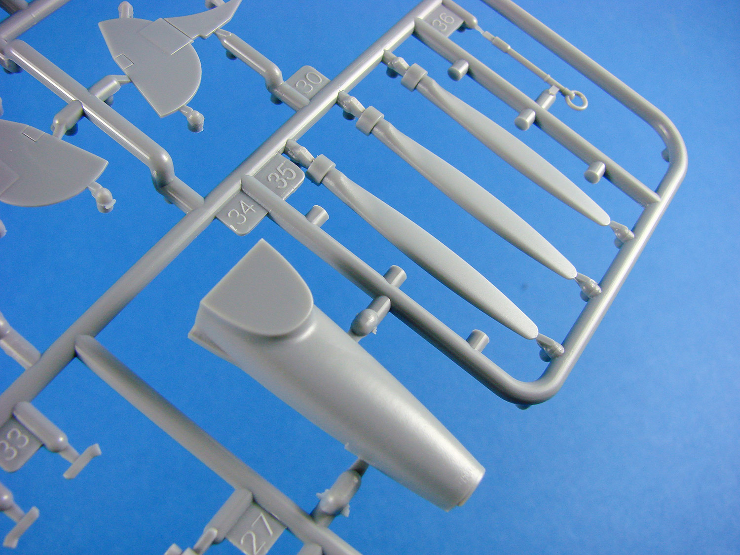

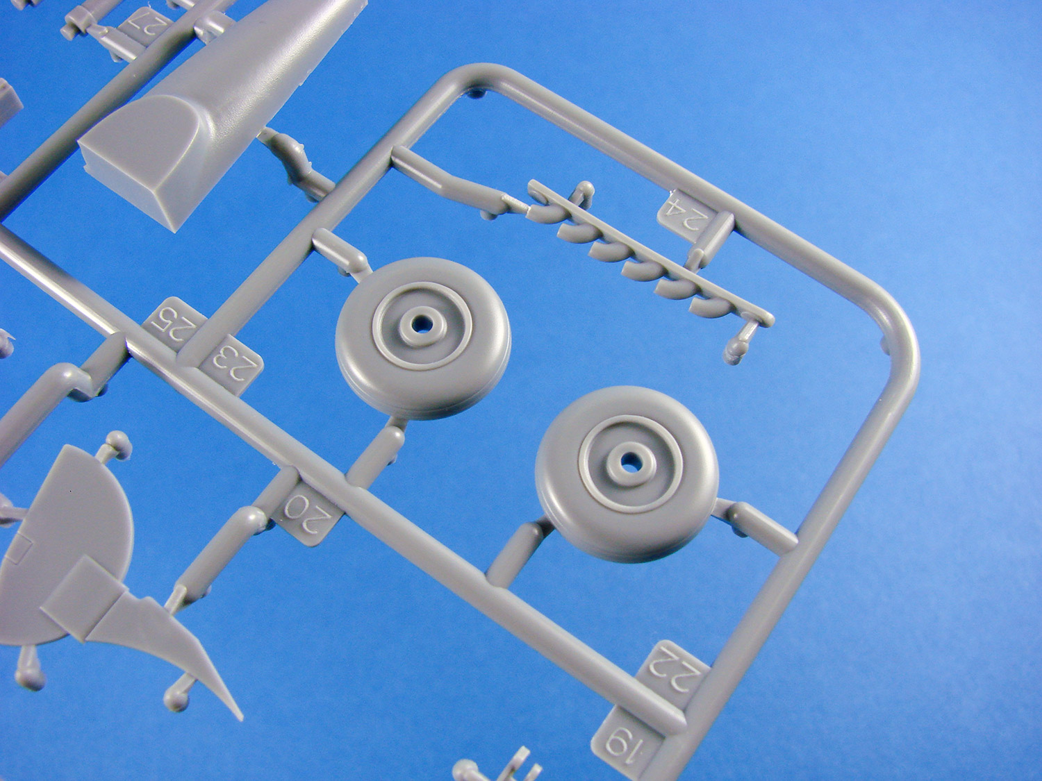

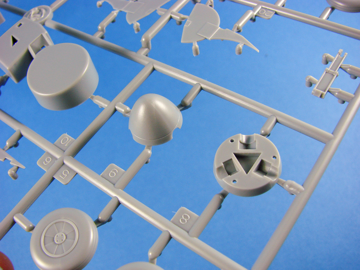

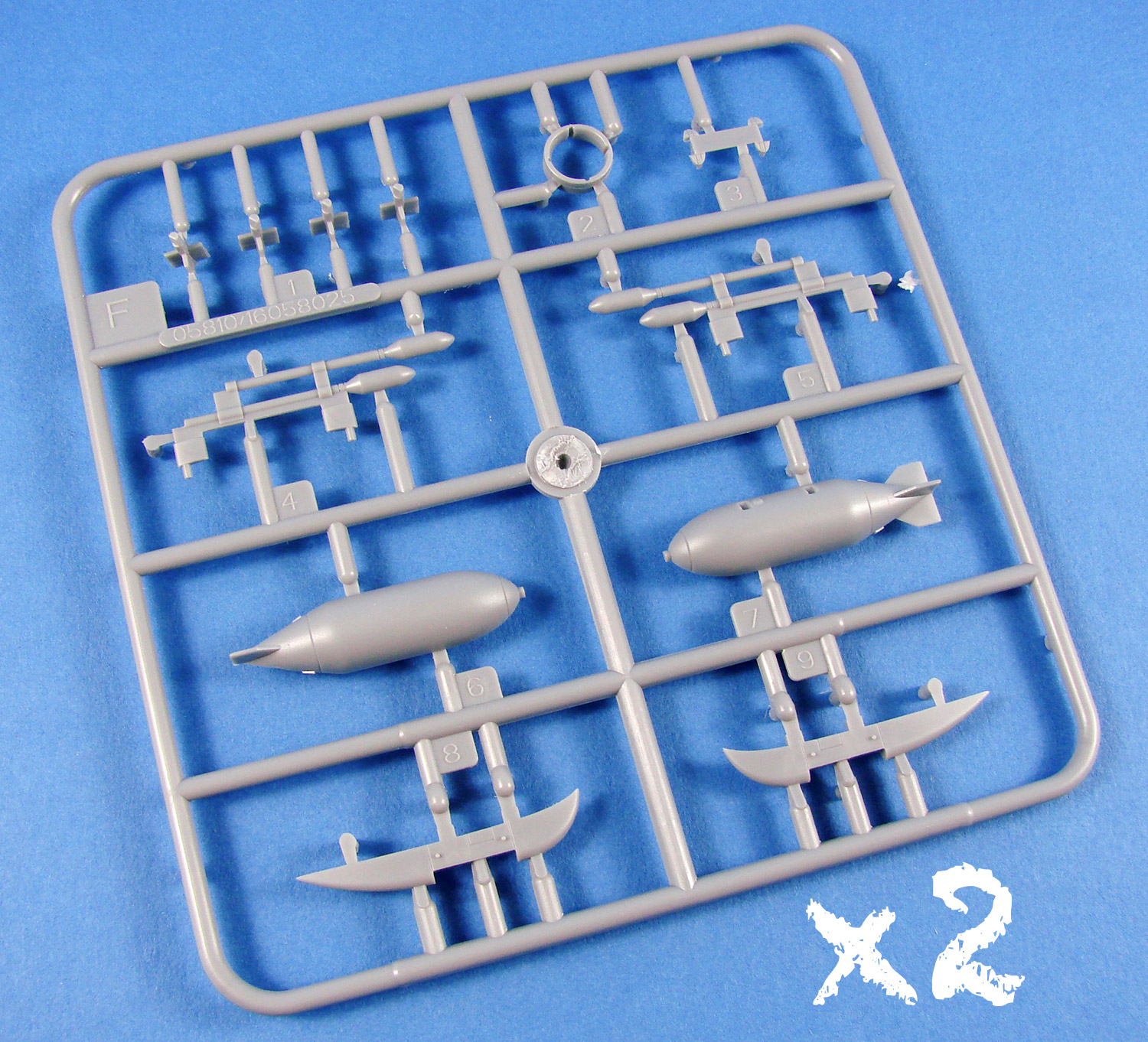


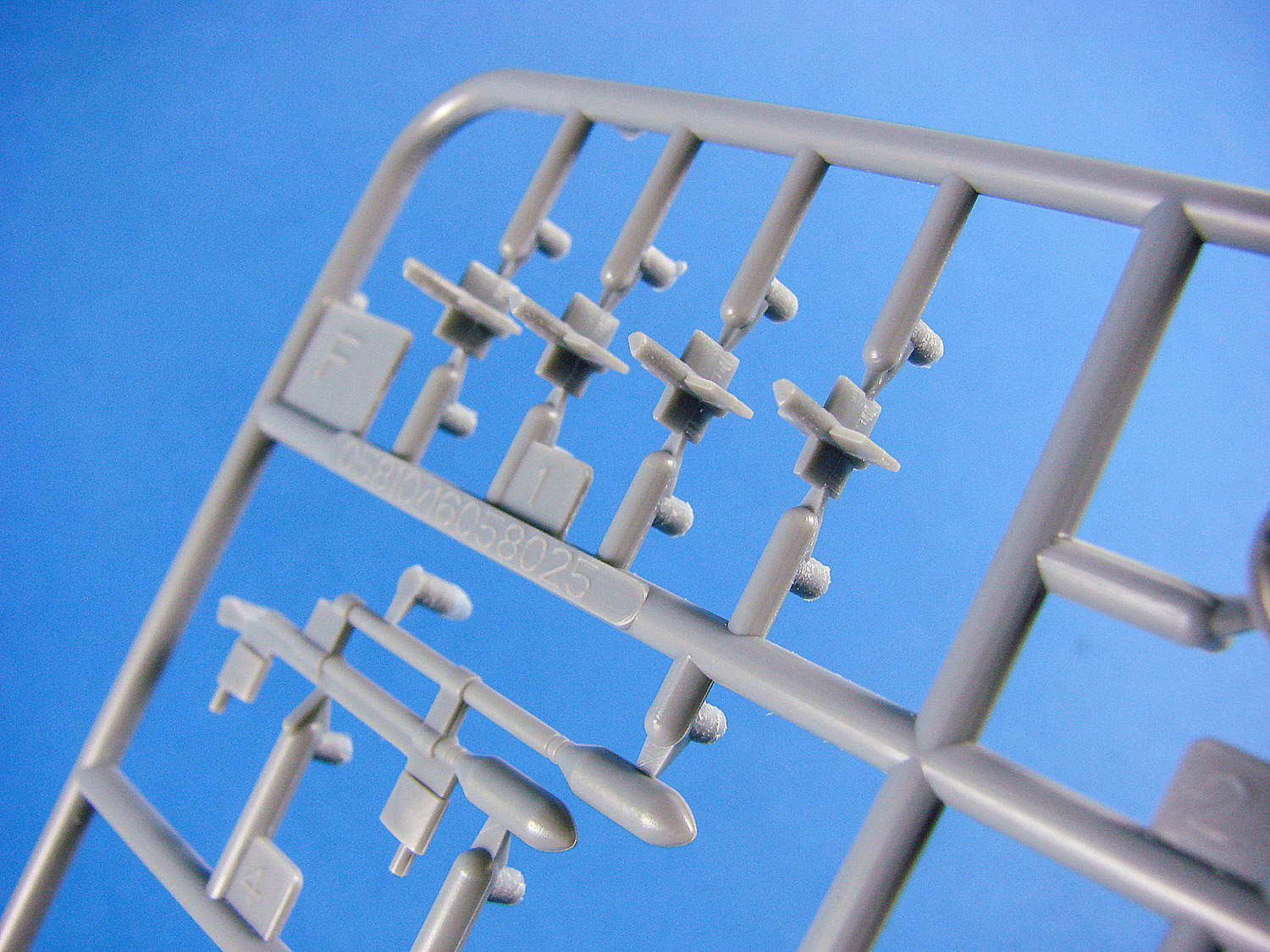
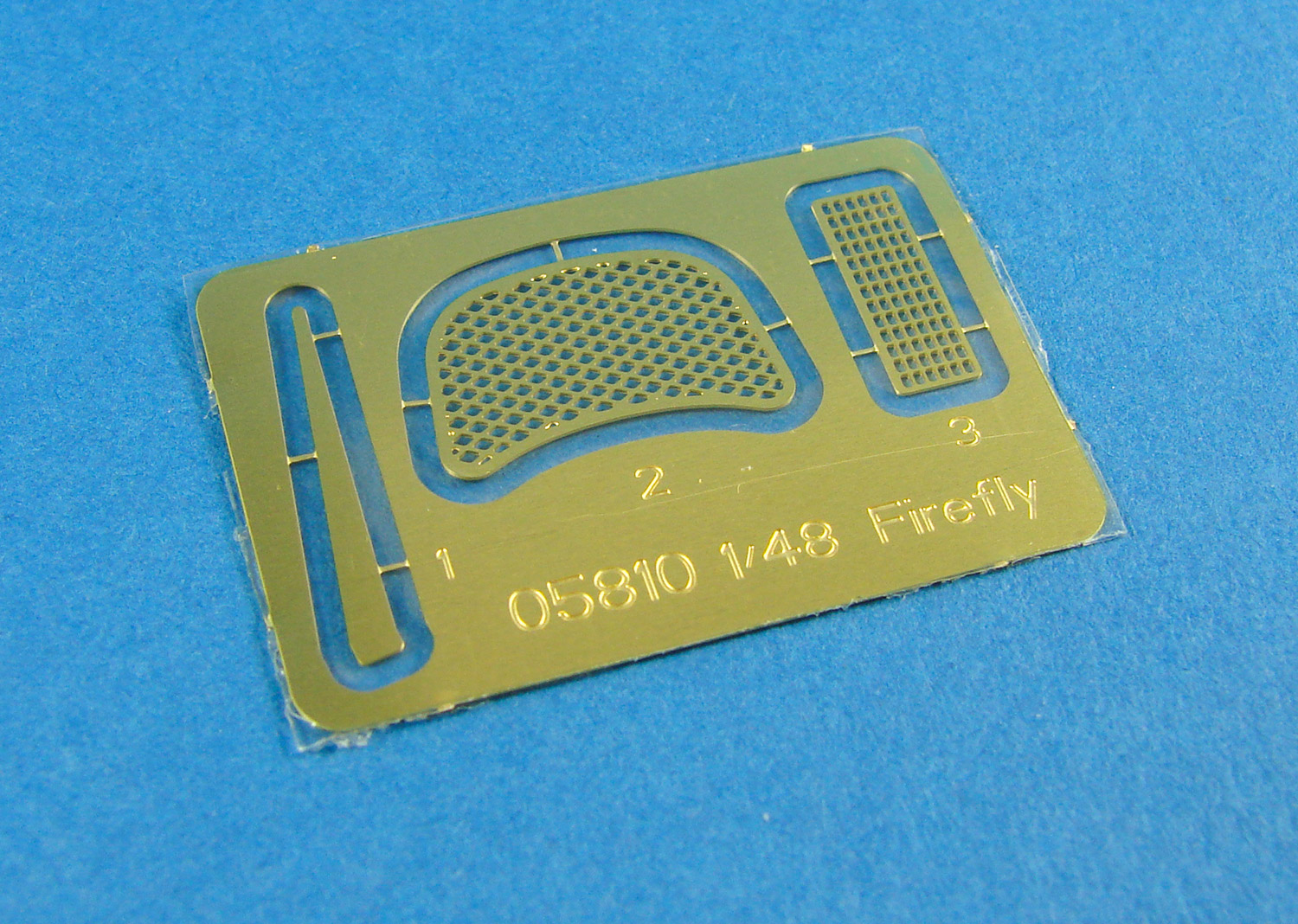


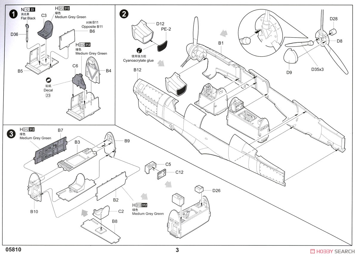
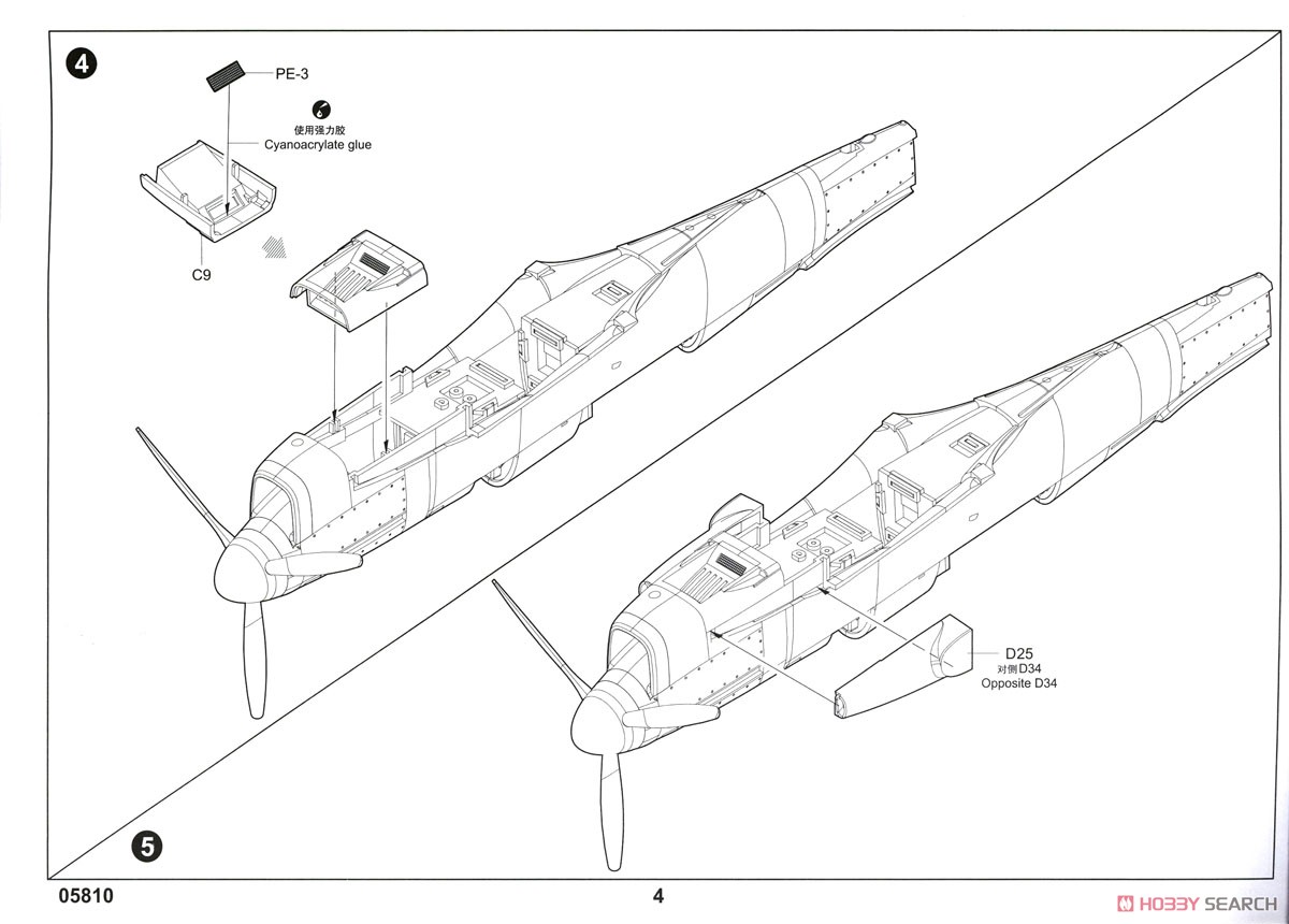
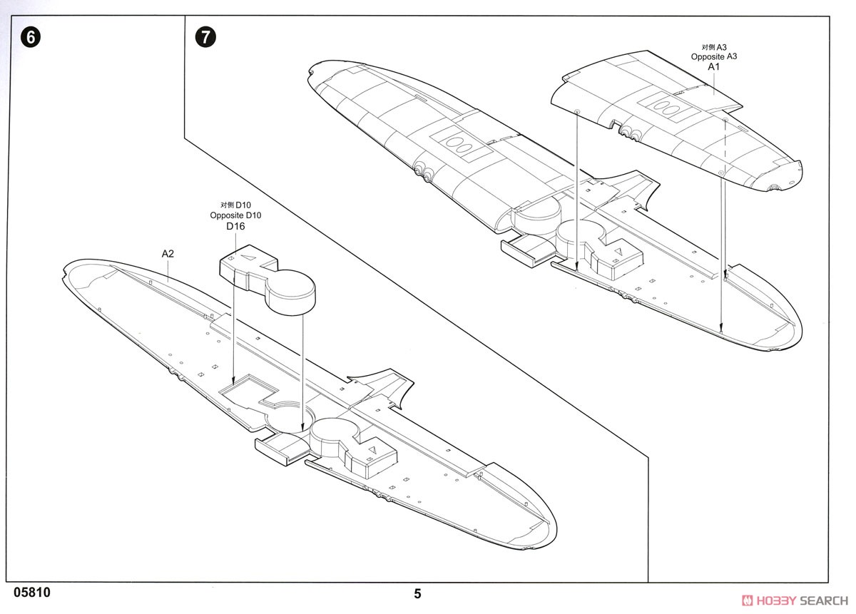


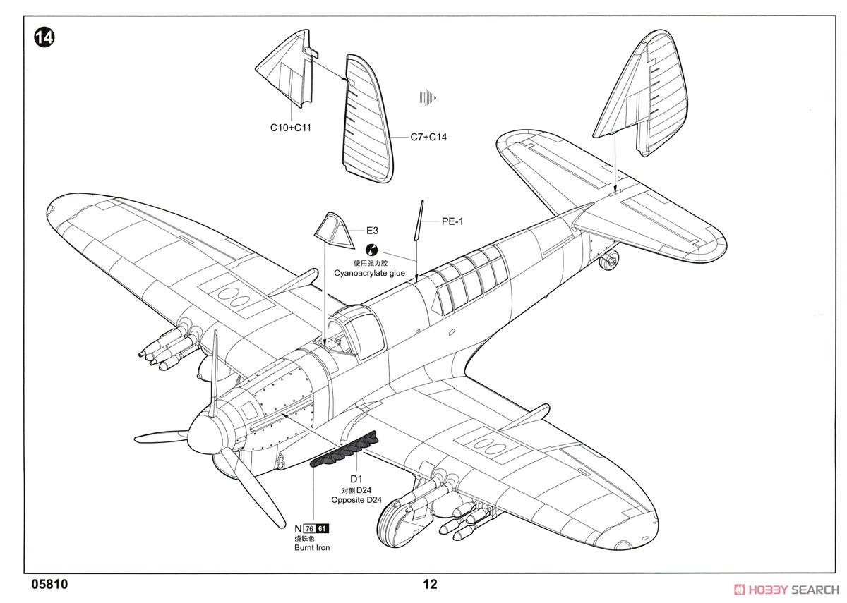


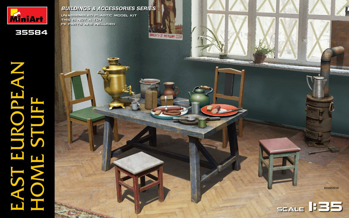
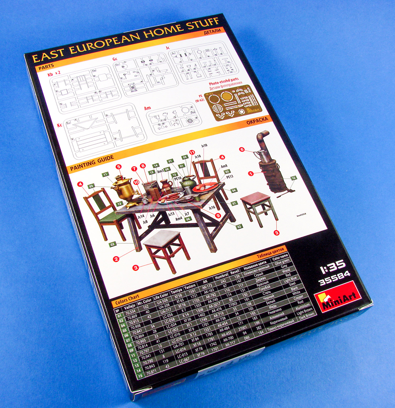
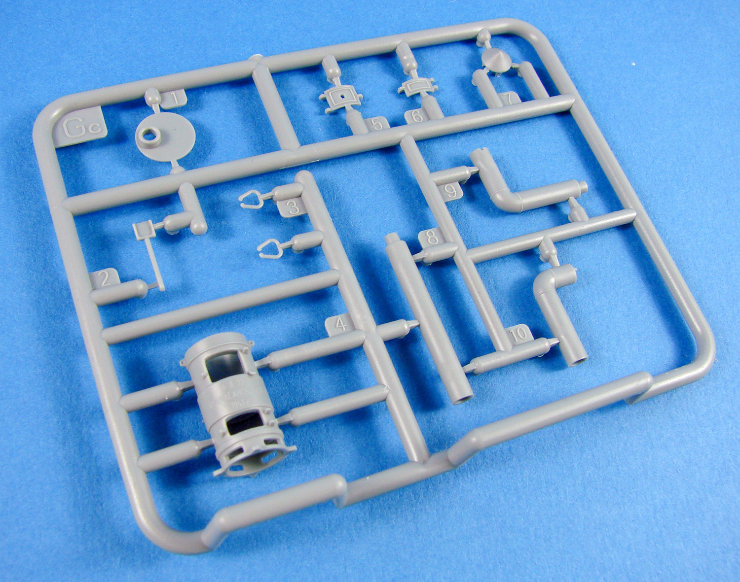


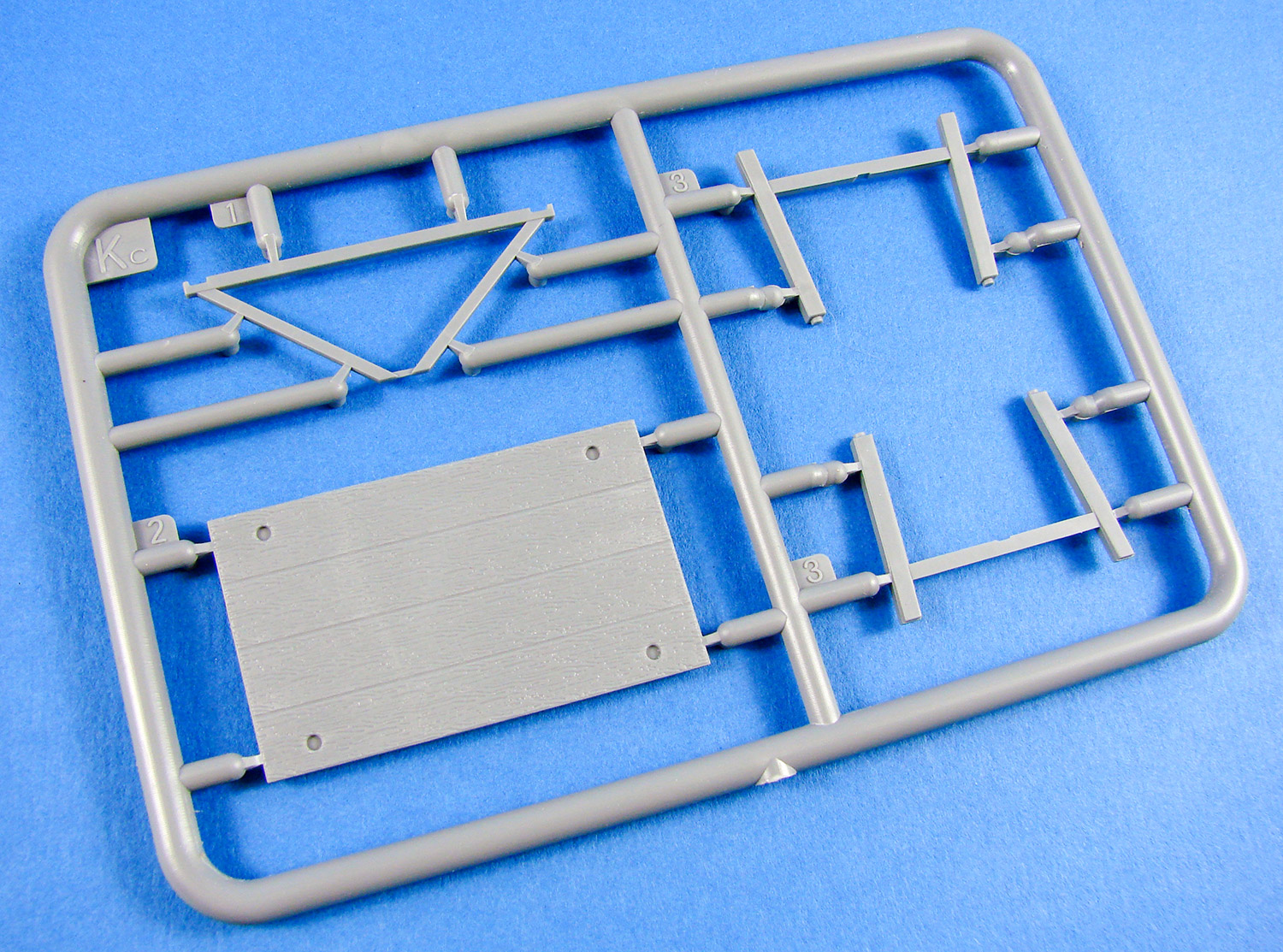

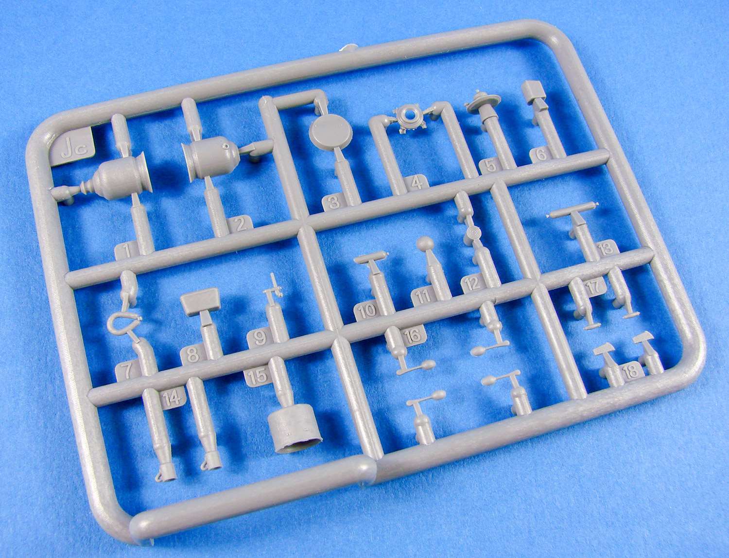

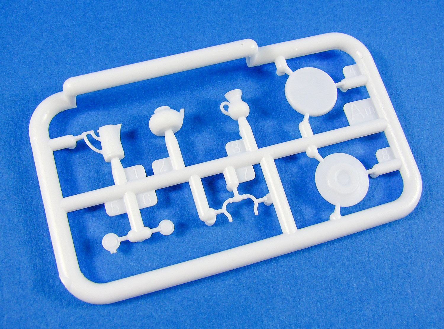
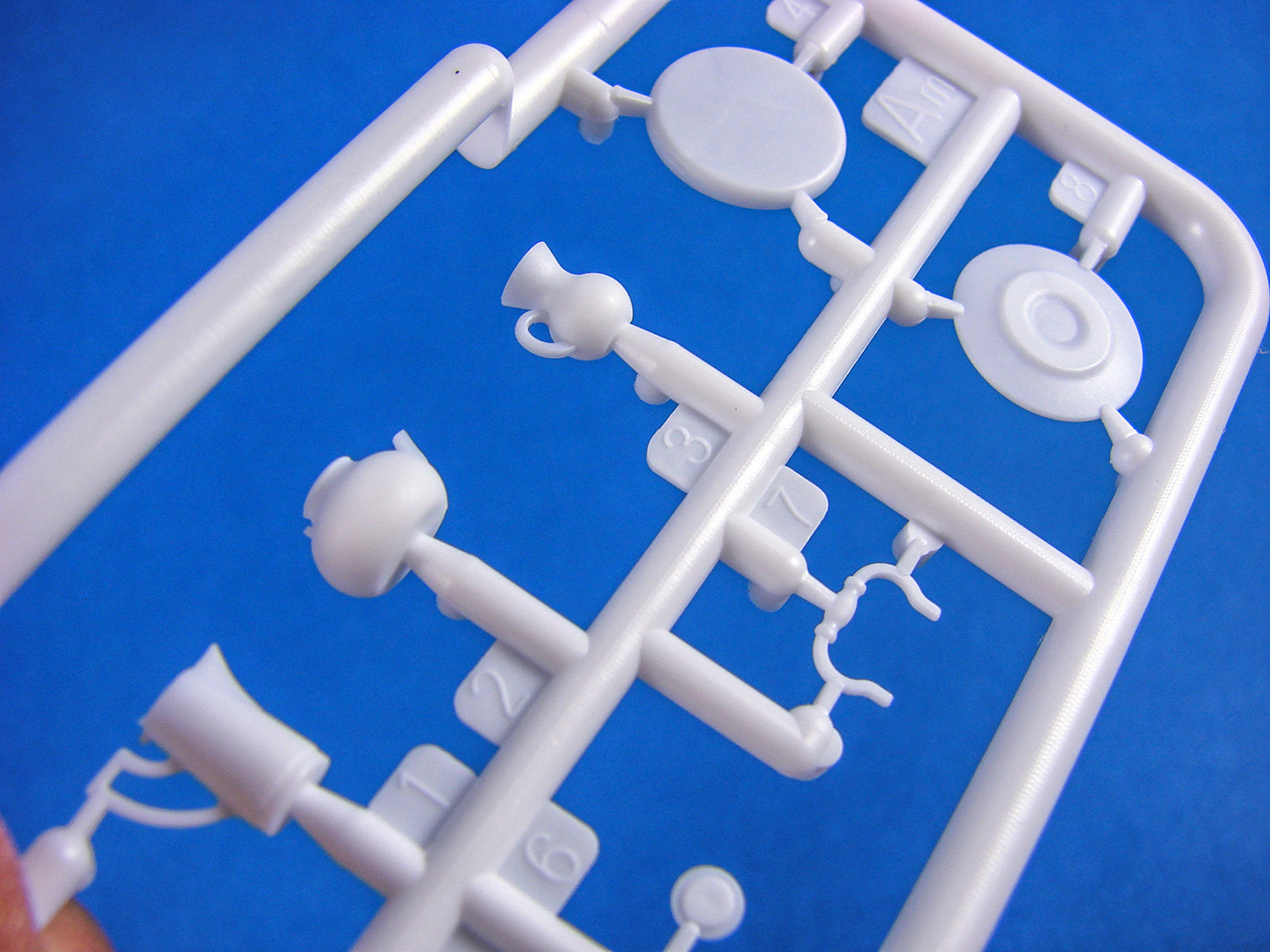
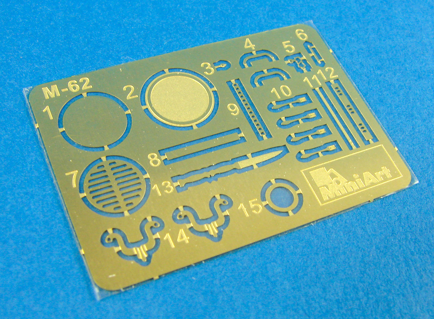

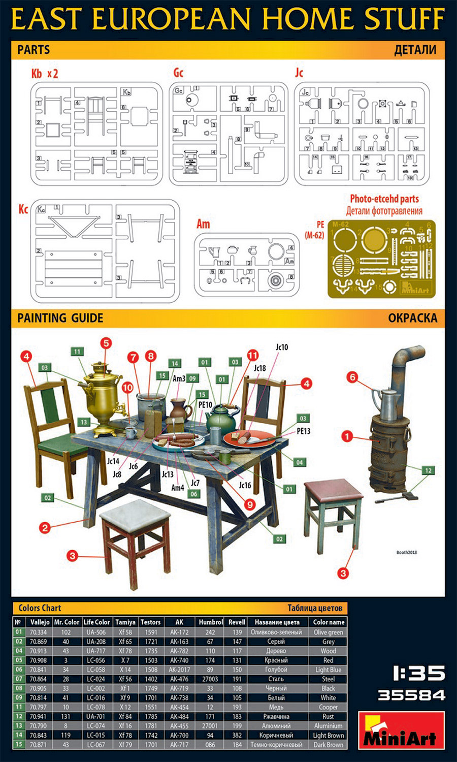


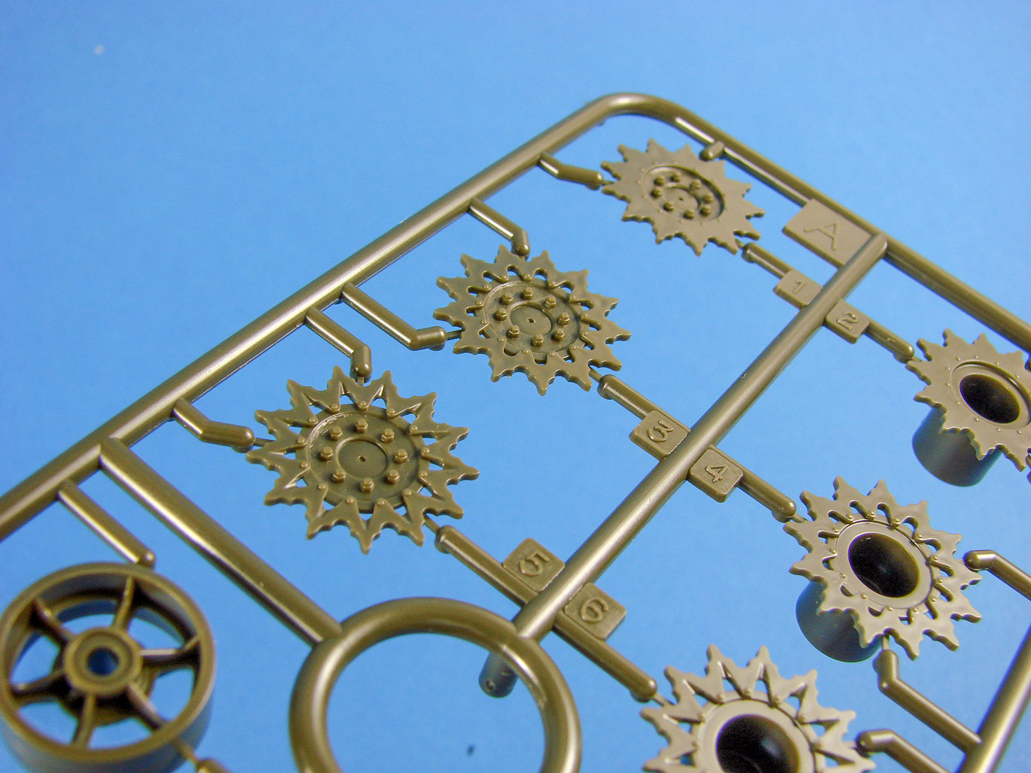
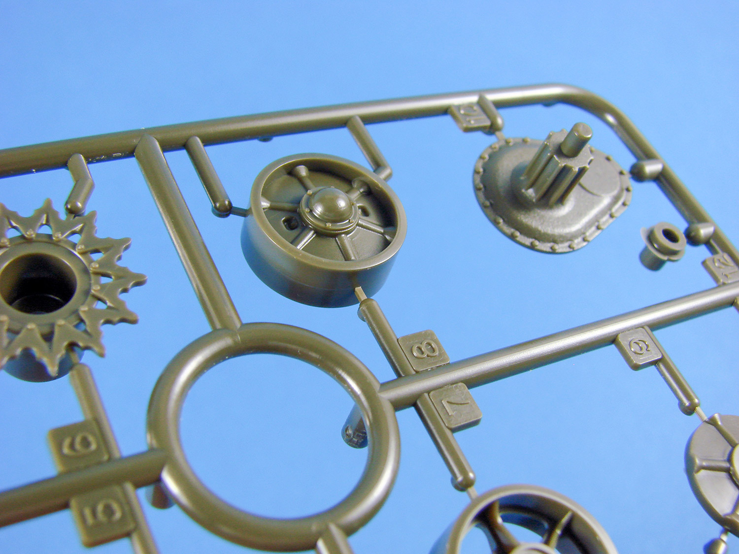

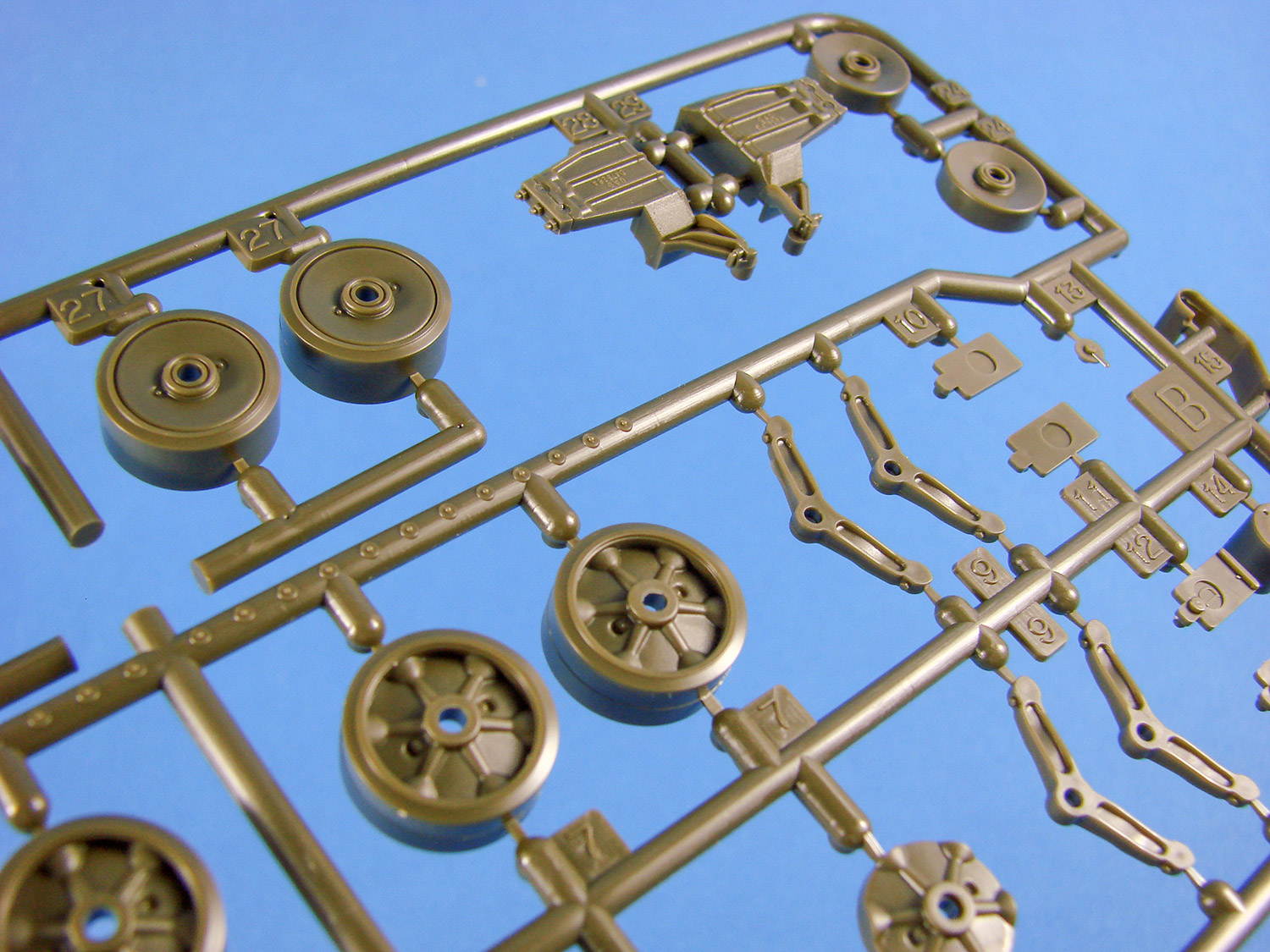

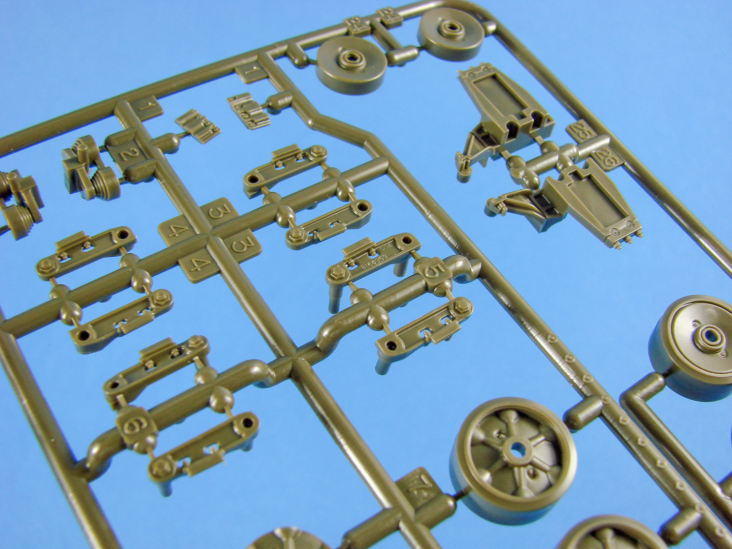


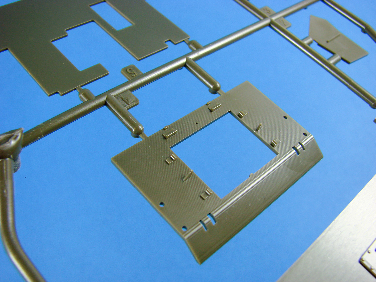
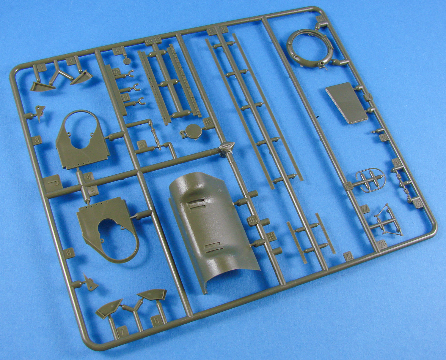

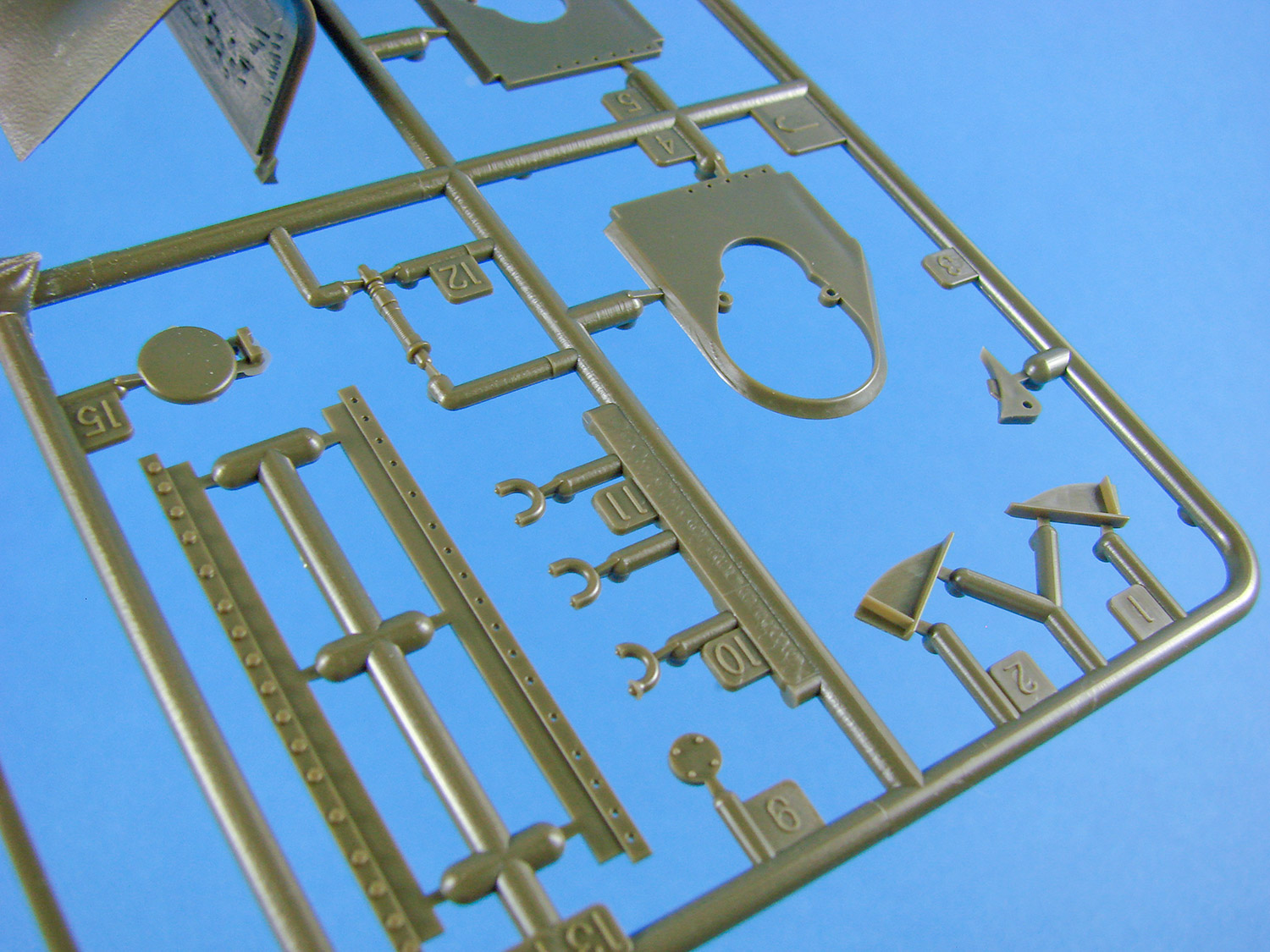


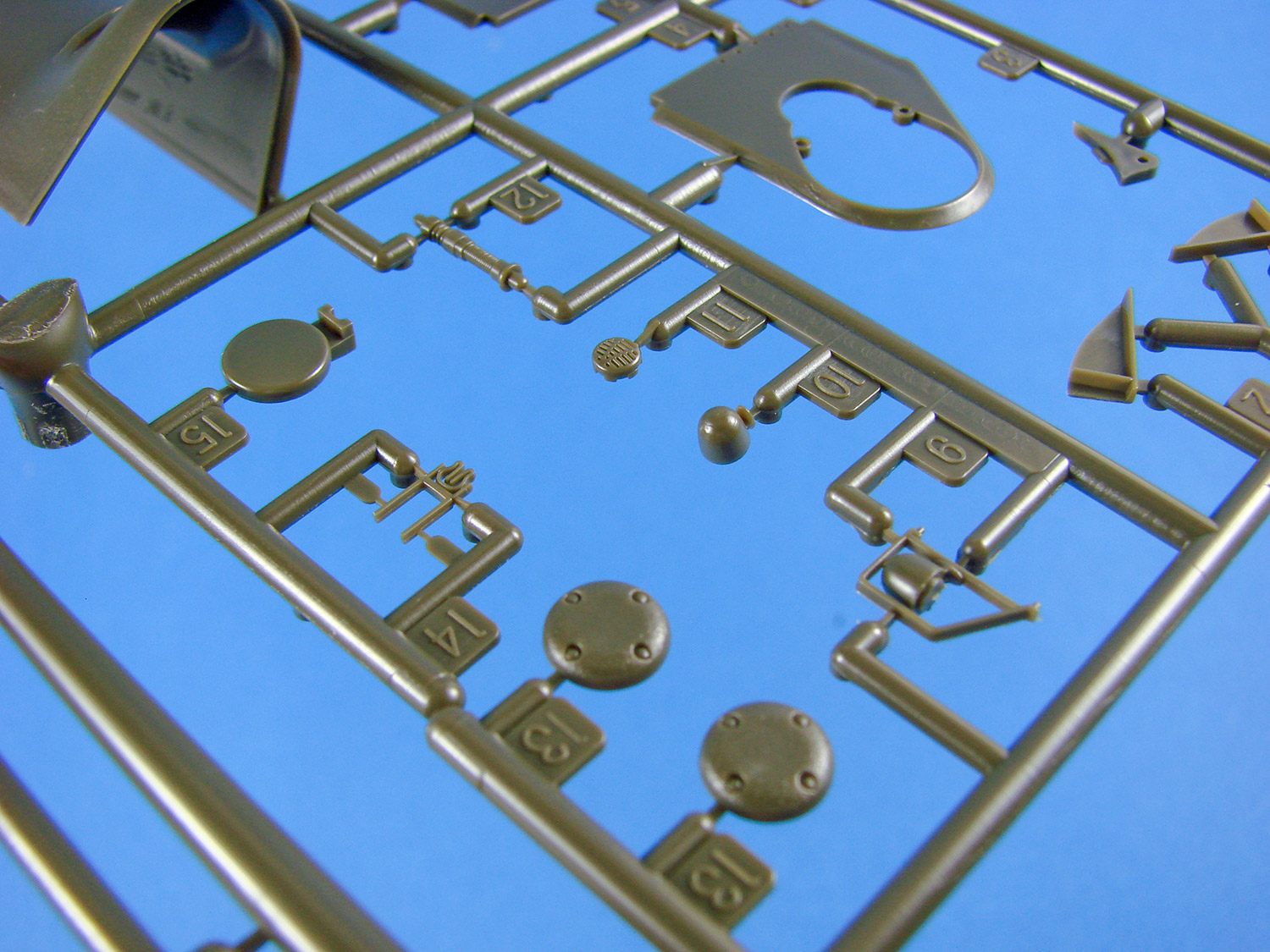
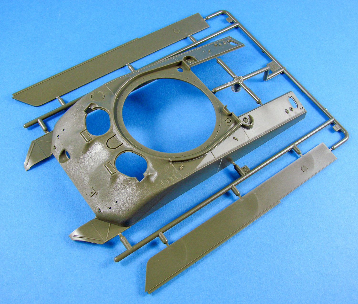
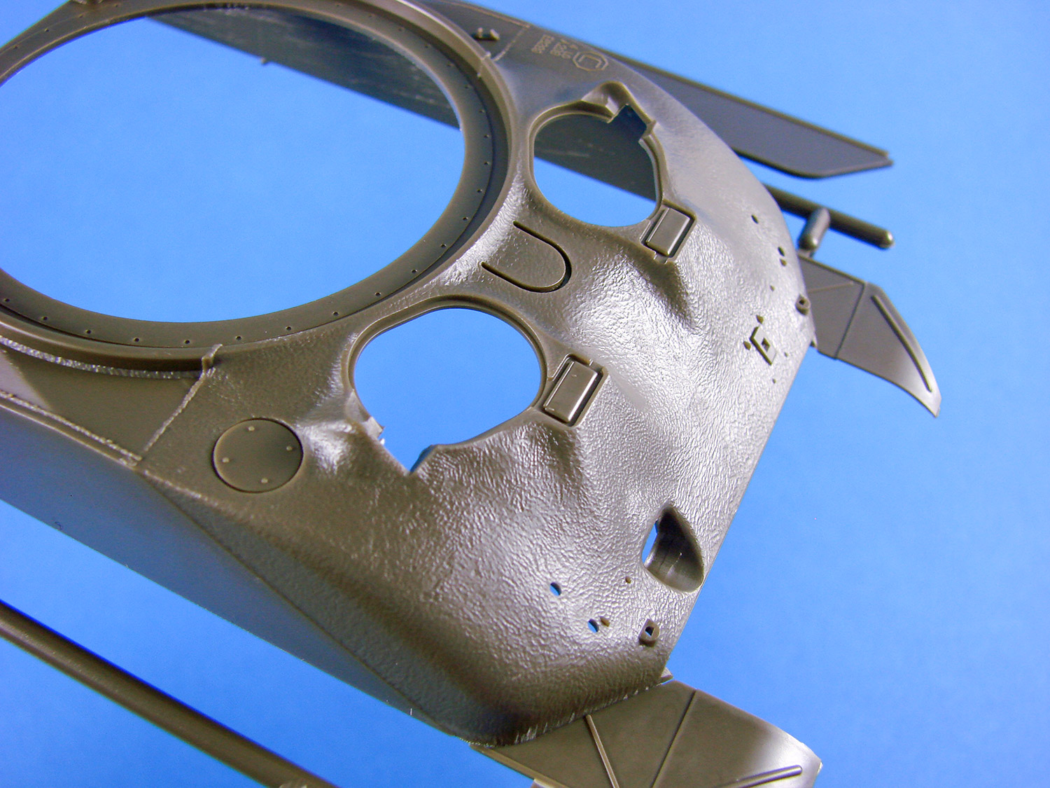
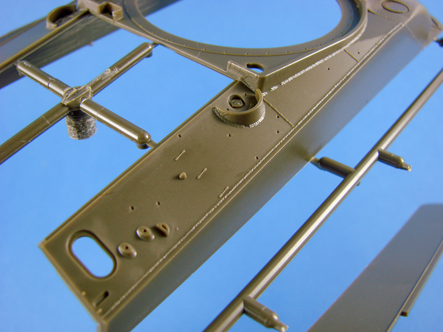

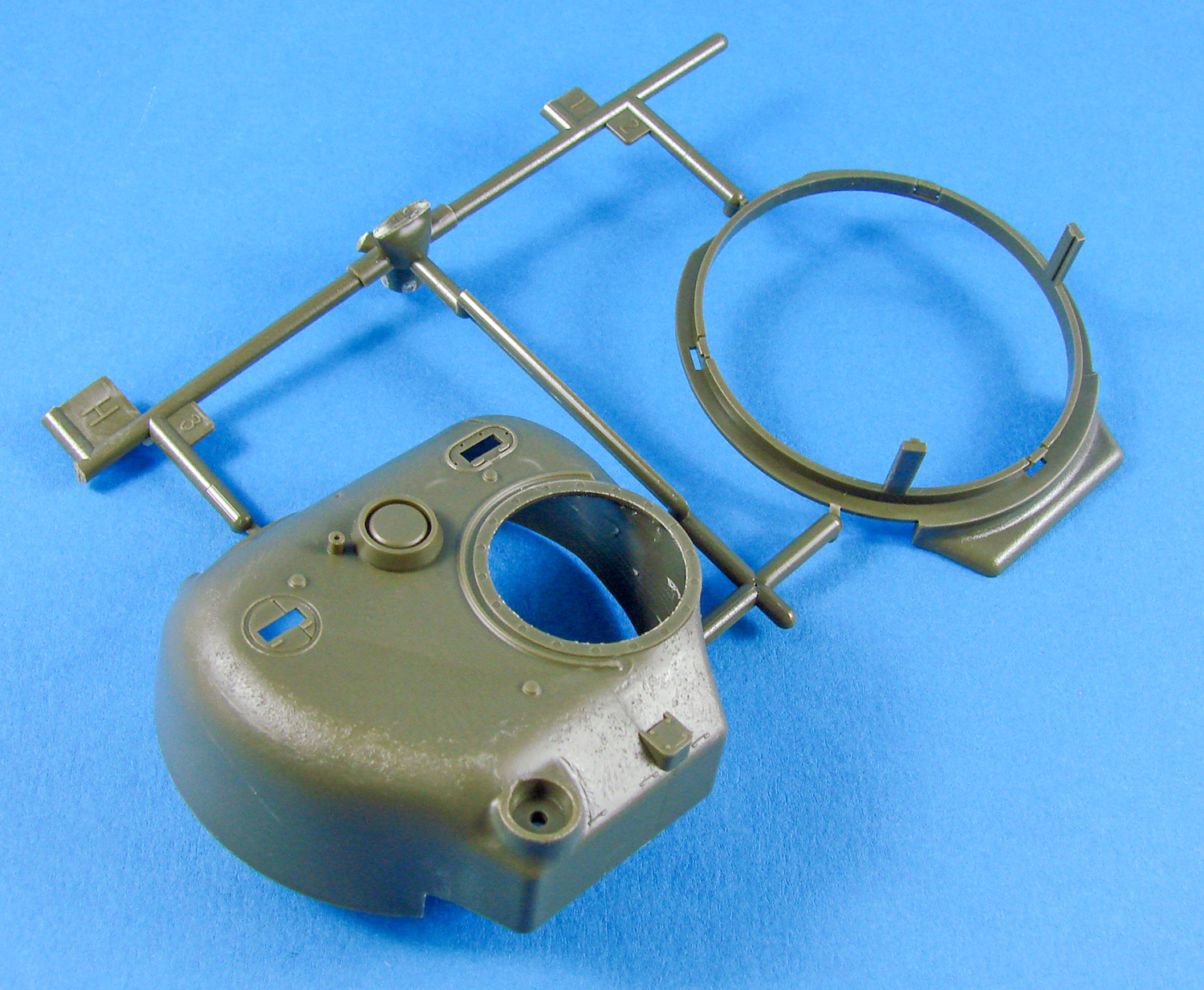
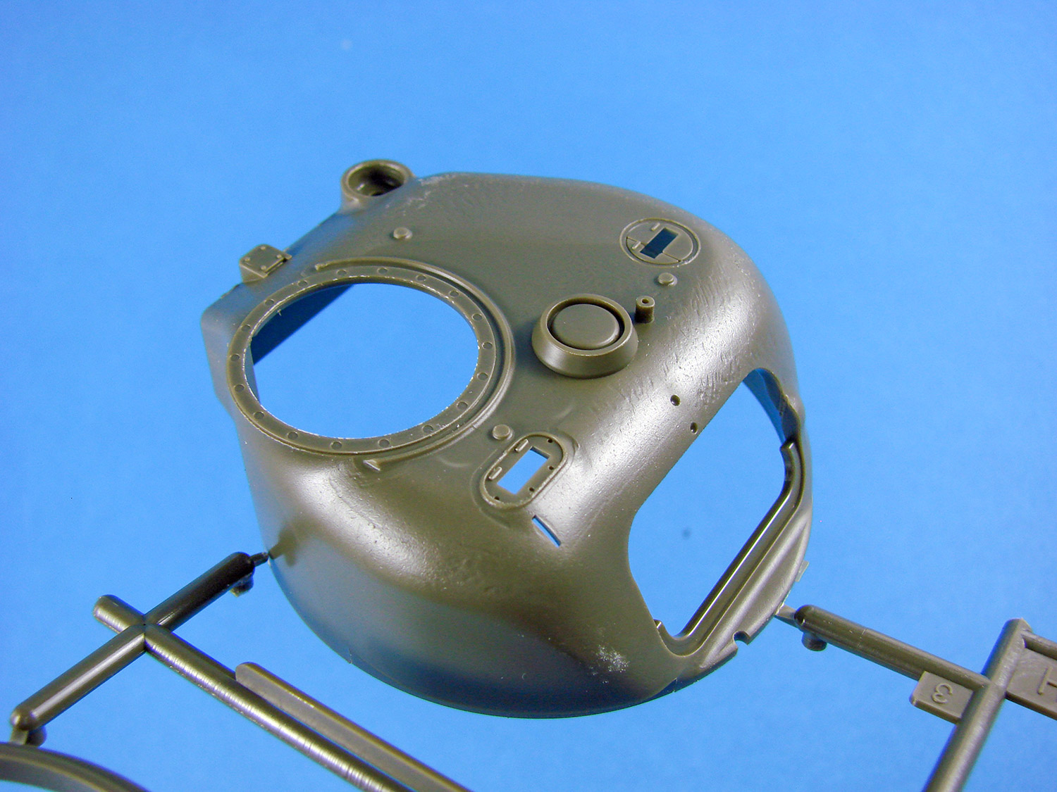

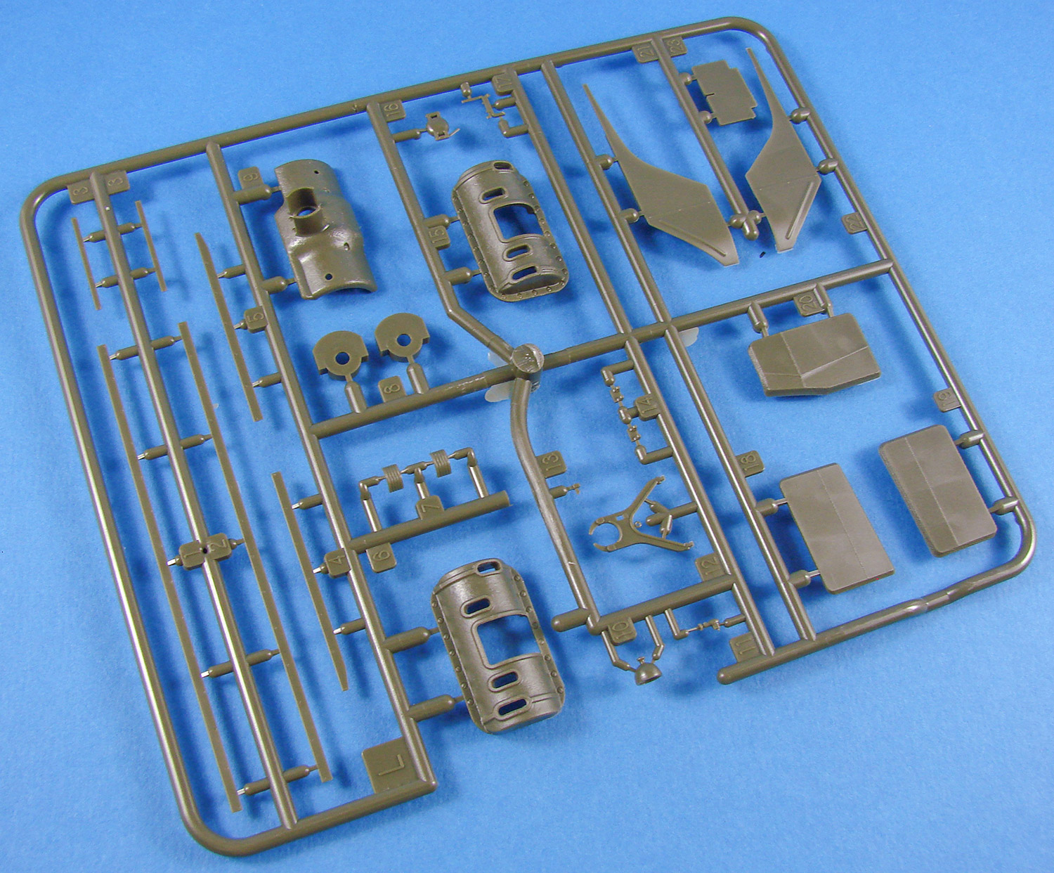
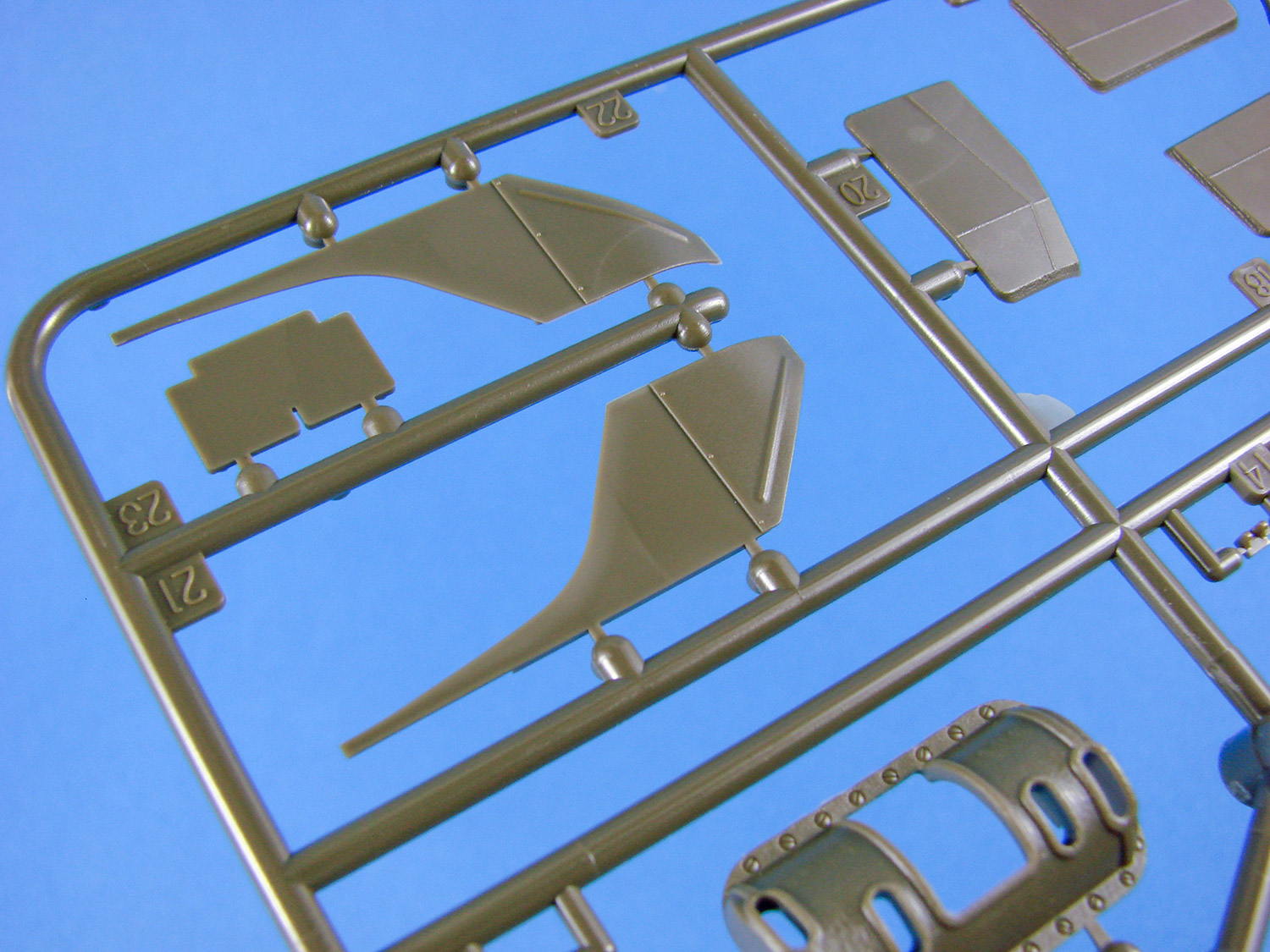
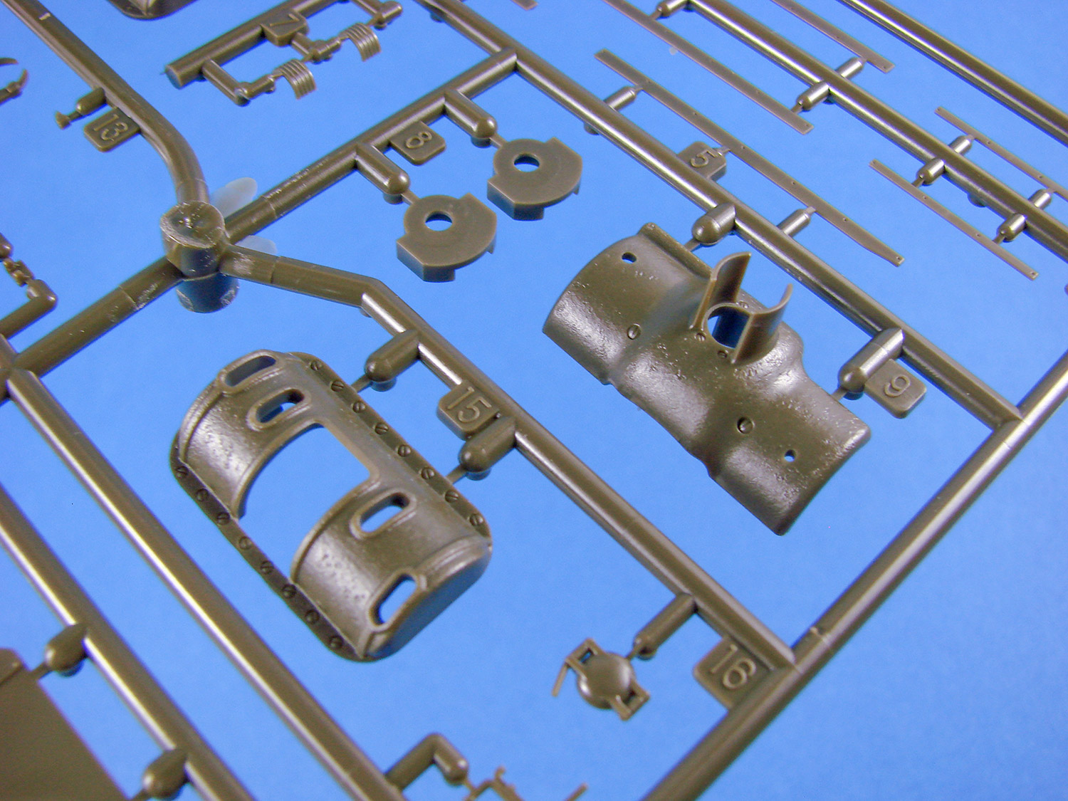


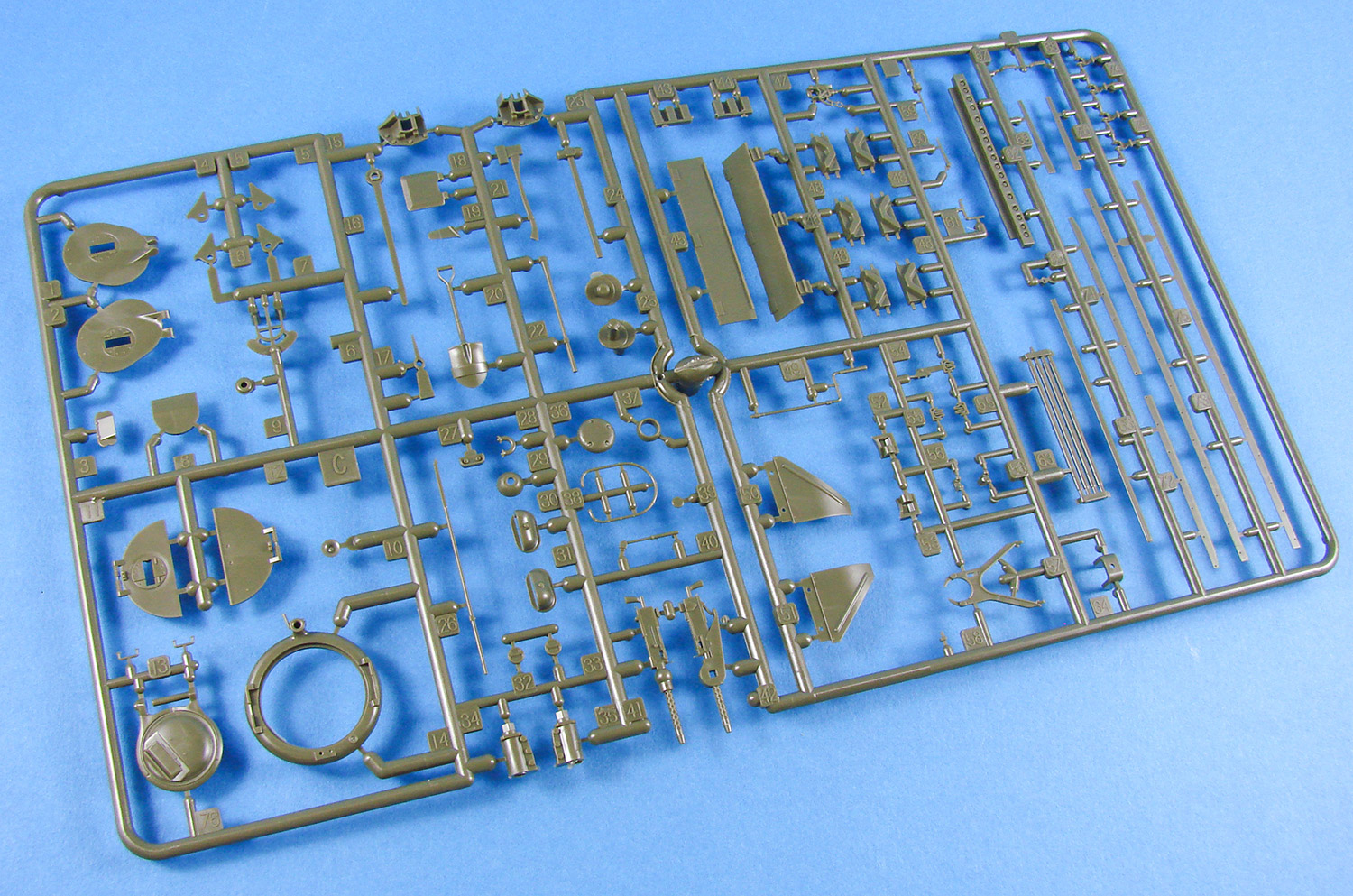
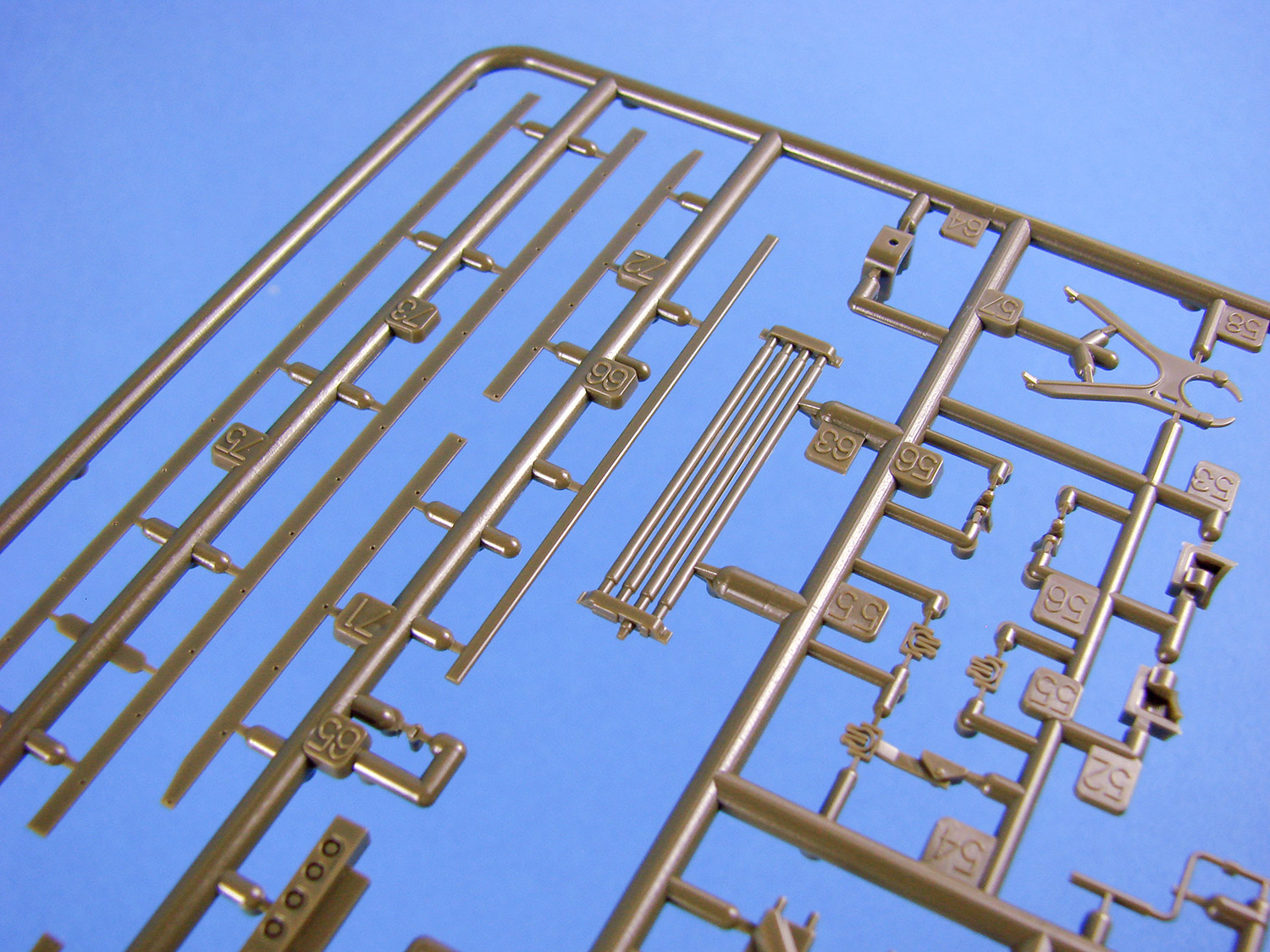
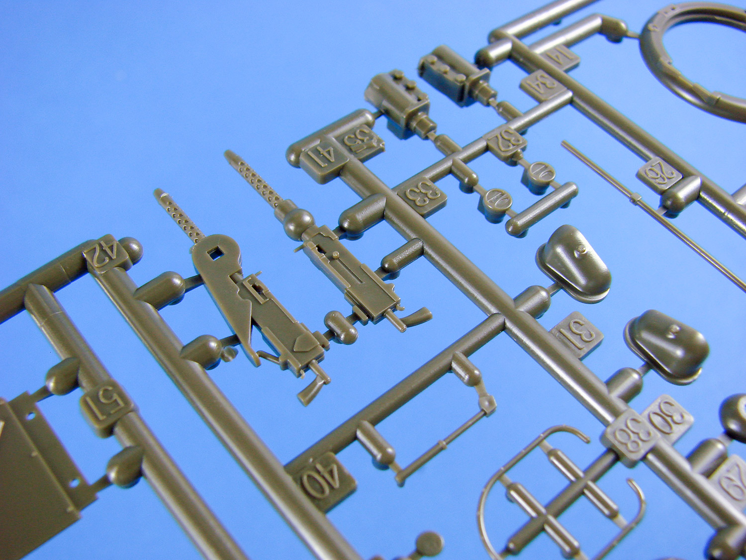
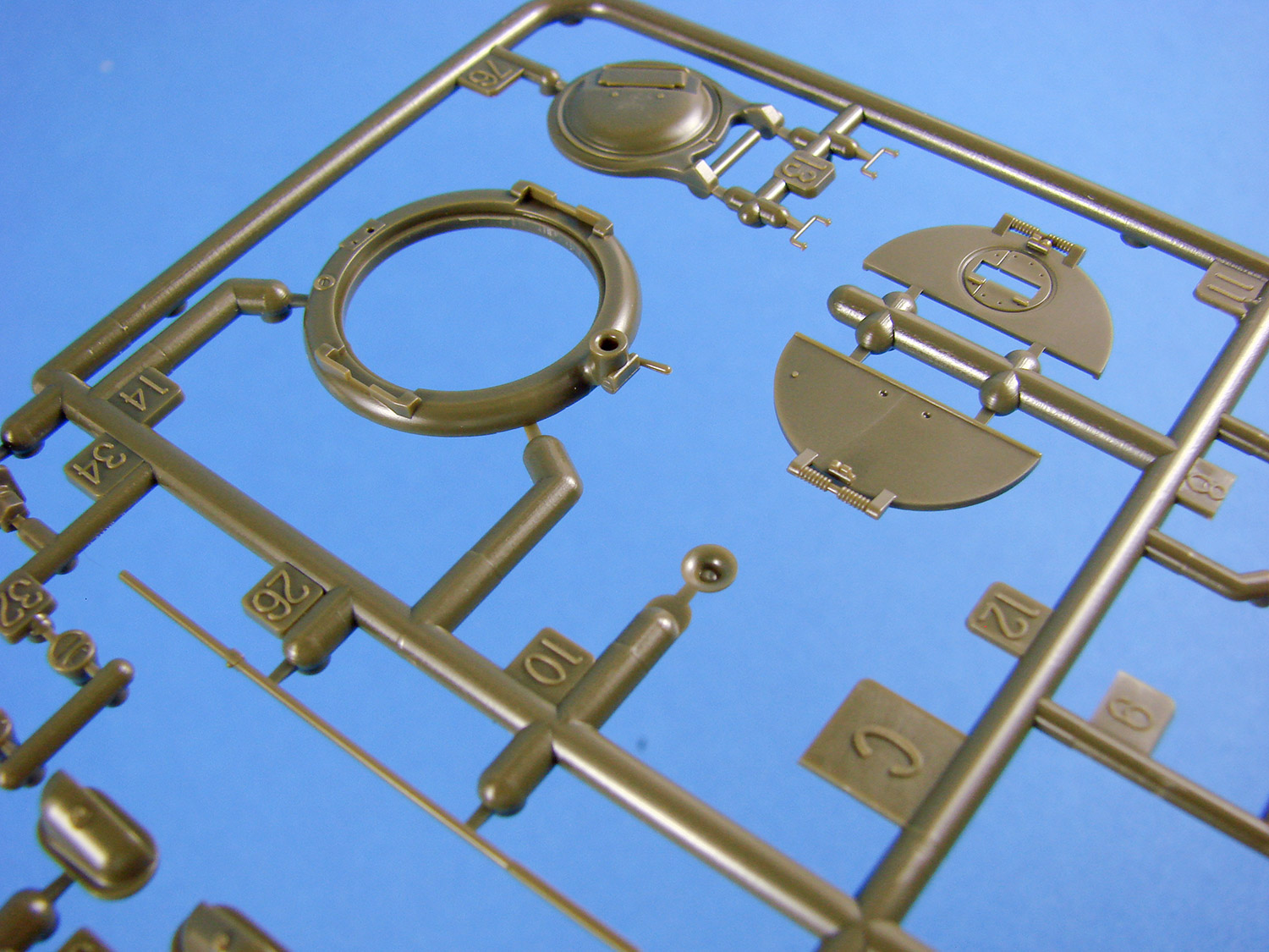


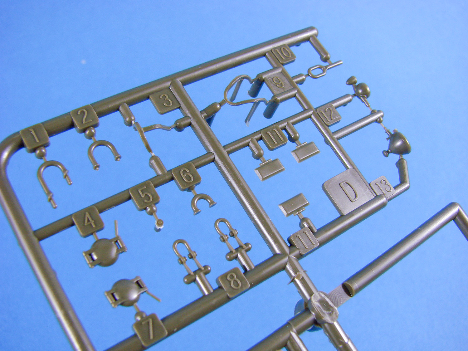

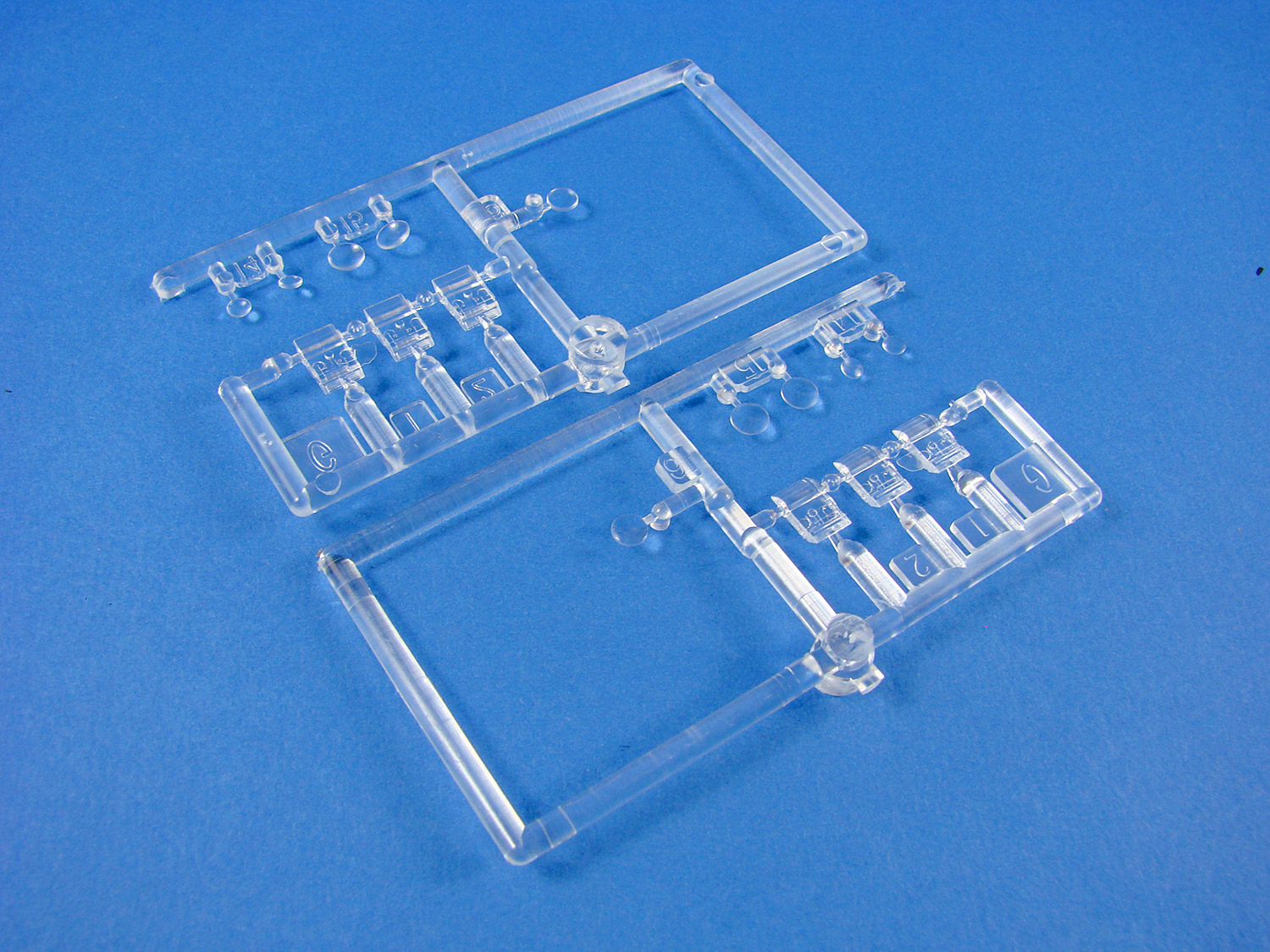
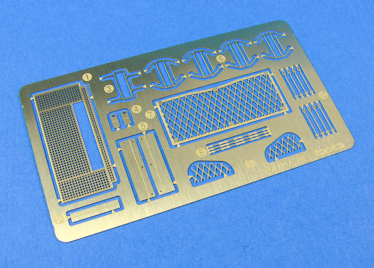
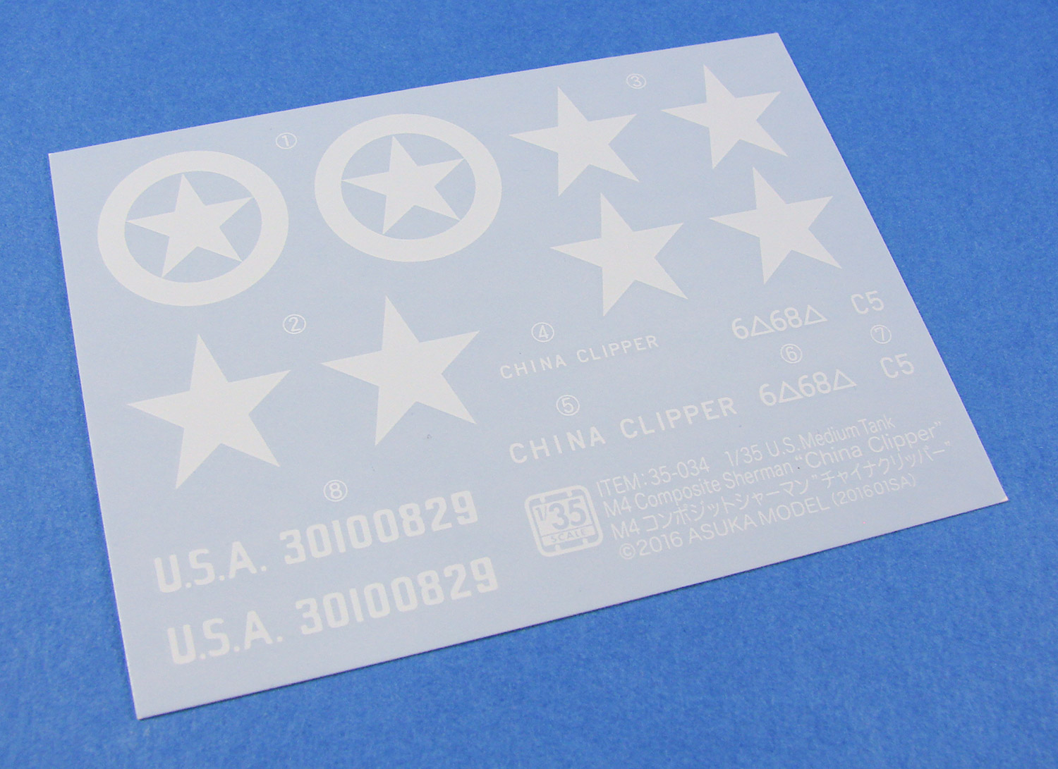
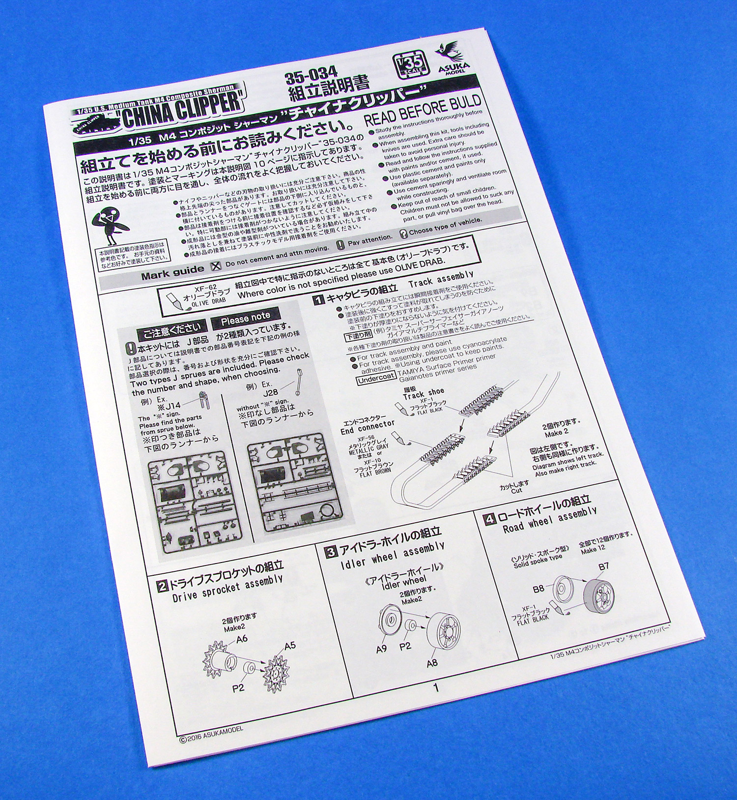
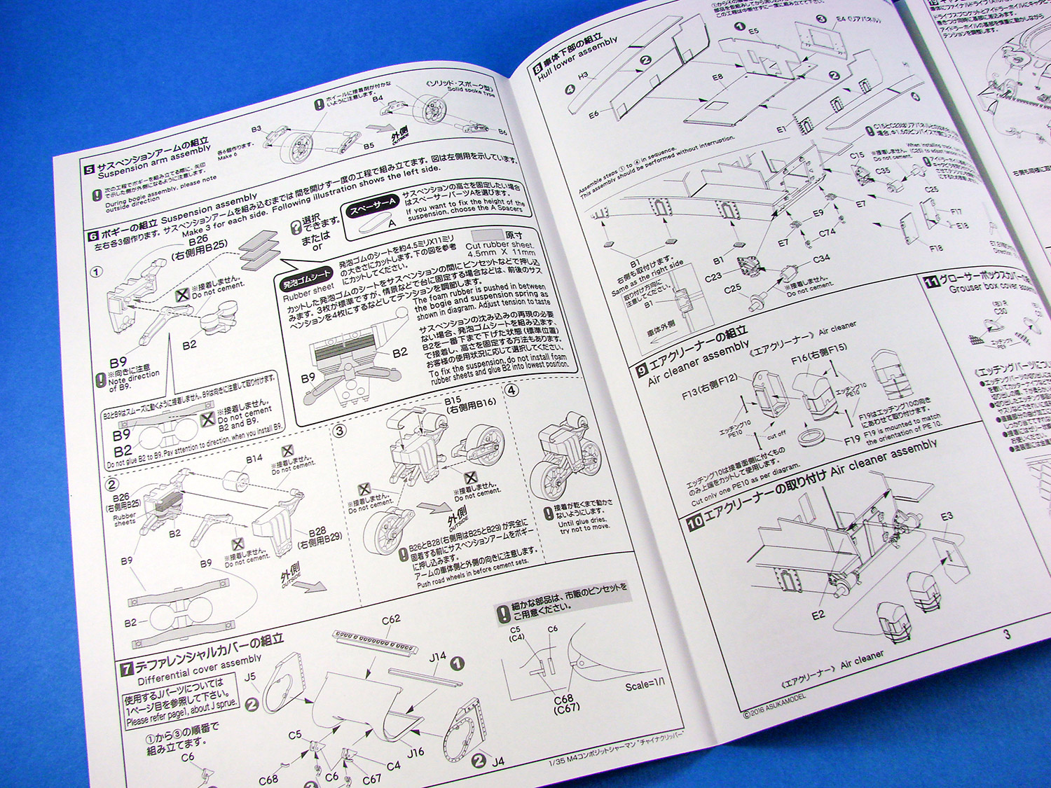
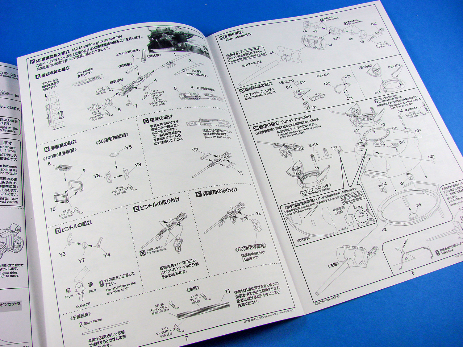
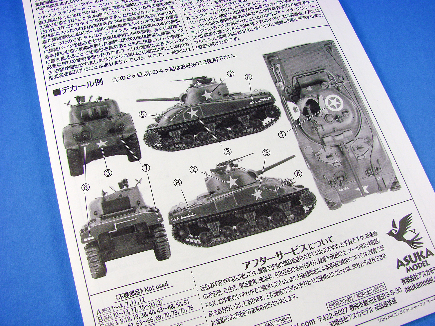


Newbie saying hi
in General Discussion
Posted
Nice to see you here Phil!
Another waiting for the HKM Lanc?")