JayDee
-
Posts
3,281 -
Joined
-
Last visited
Content Type
Profiles
Forums
Events
Gallery
Everything posted by JayDee
-
border model Border Model 1:35 Heinkel He 111H-6
JayDee replied to JayDee's topic in Aircraft Reviews
While some will piss and moan about 1:35, more will about the surface details. While the externals look incredible, I am aware of the raised rivets anomaly, but I was when I asked for this kit to be sent, so it wasn't a surprise. I've seen many of the test shot images, plus the painted wing panels on the sprues. I'm happy with it generally. I may or may not do something with the rivets. It's not a deal breaker for me. -
border model Border Model 1:35 Heinkel He 111H-6
JayDee replied to JayDee's topic in Aircraft Reviews
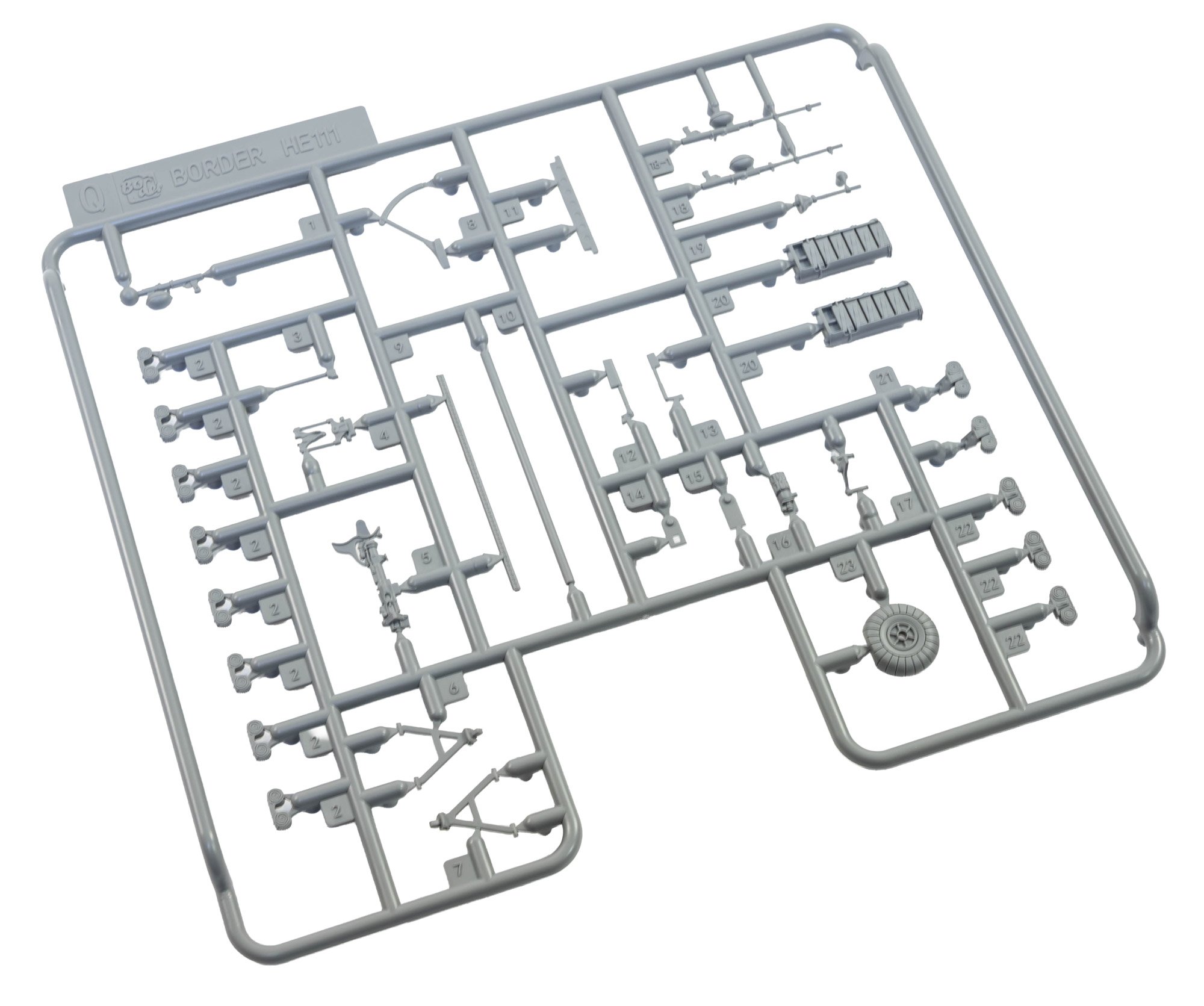
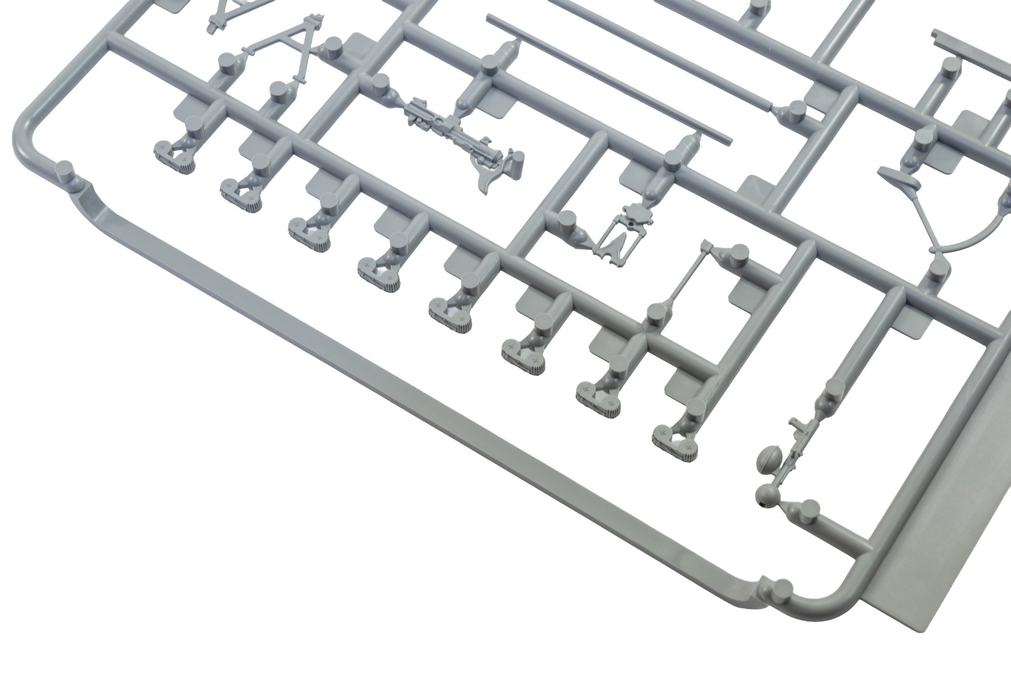
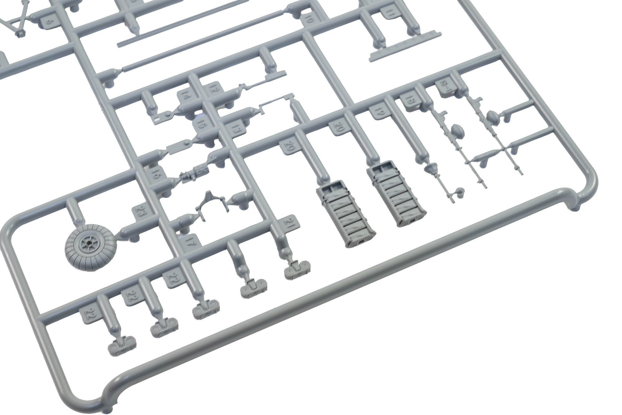
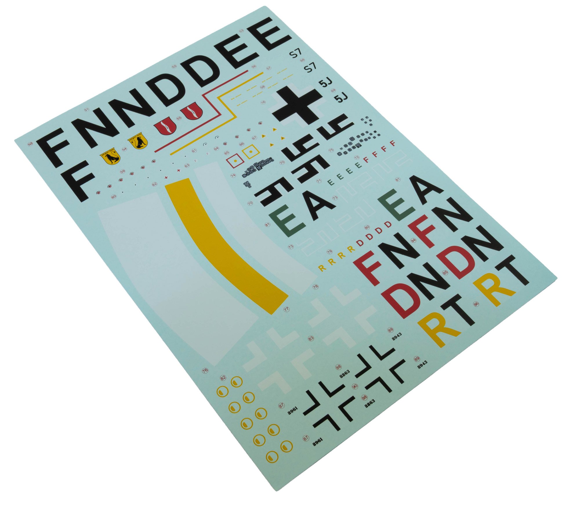
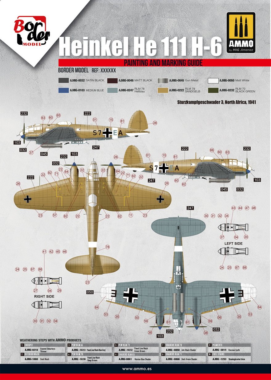
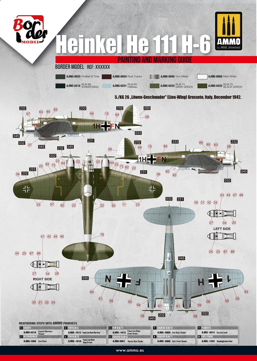
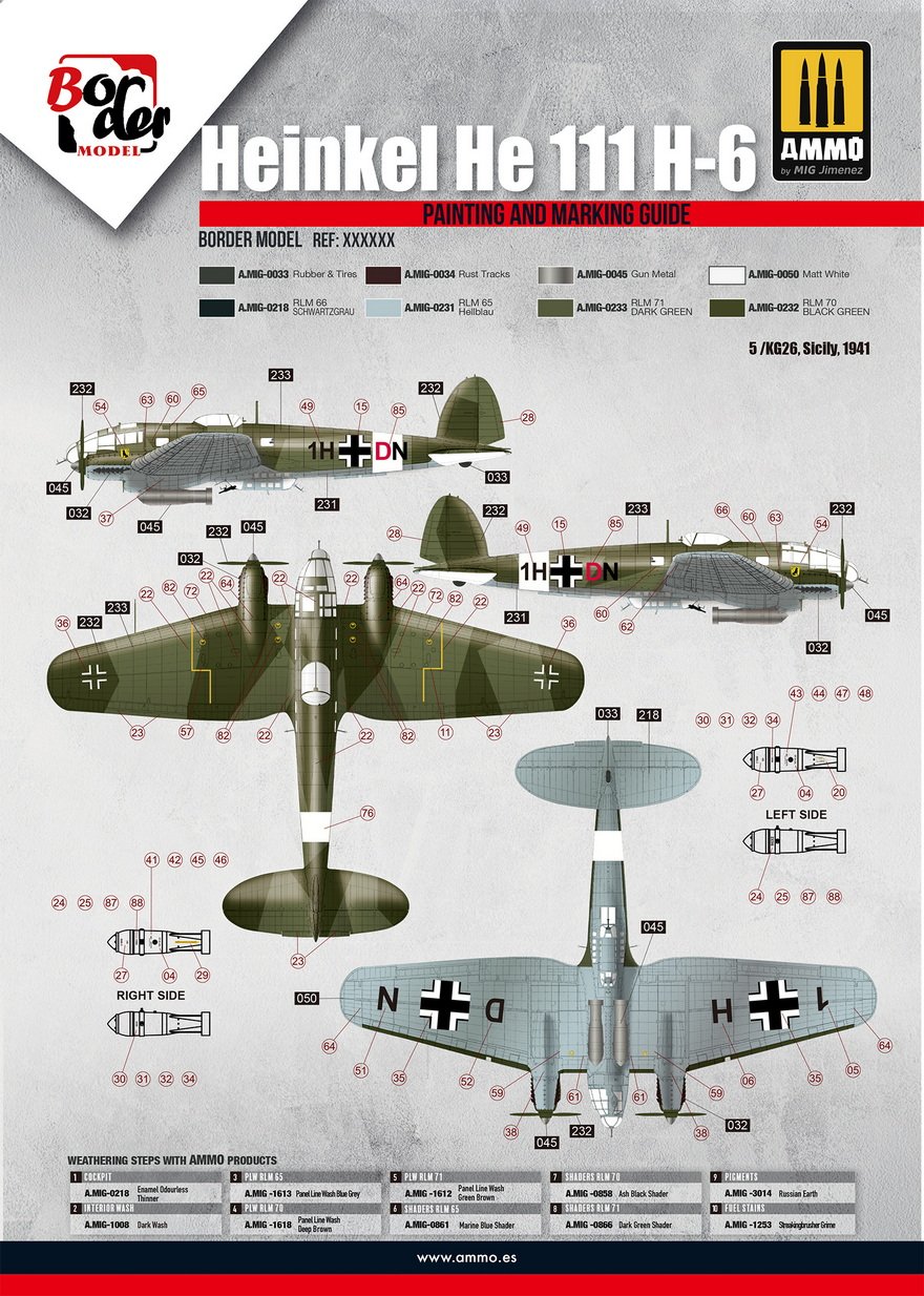
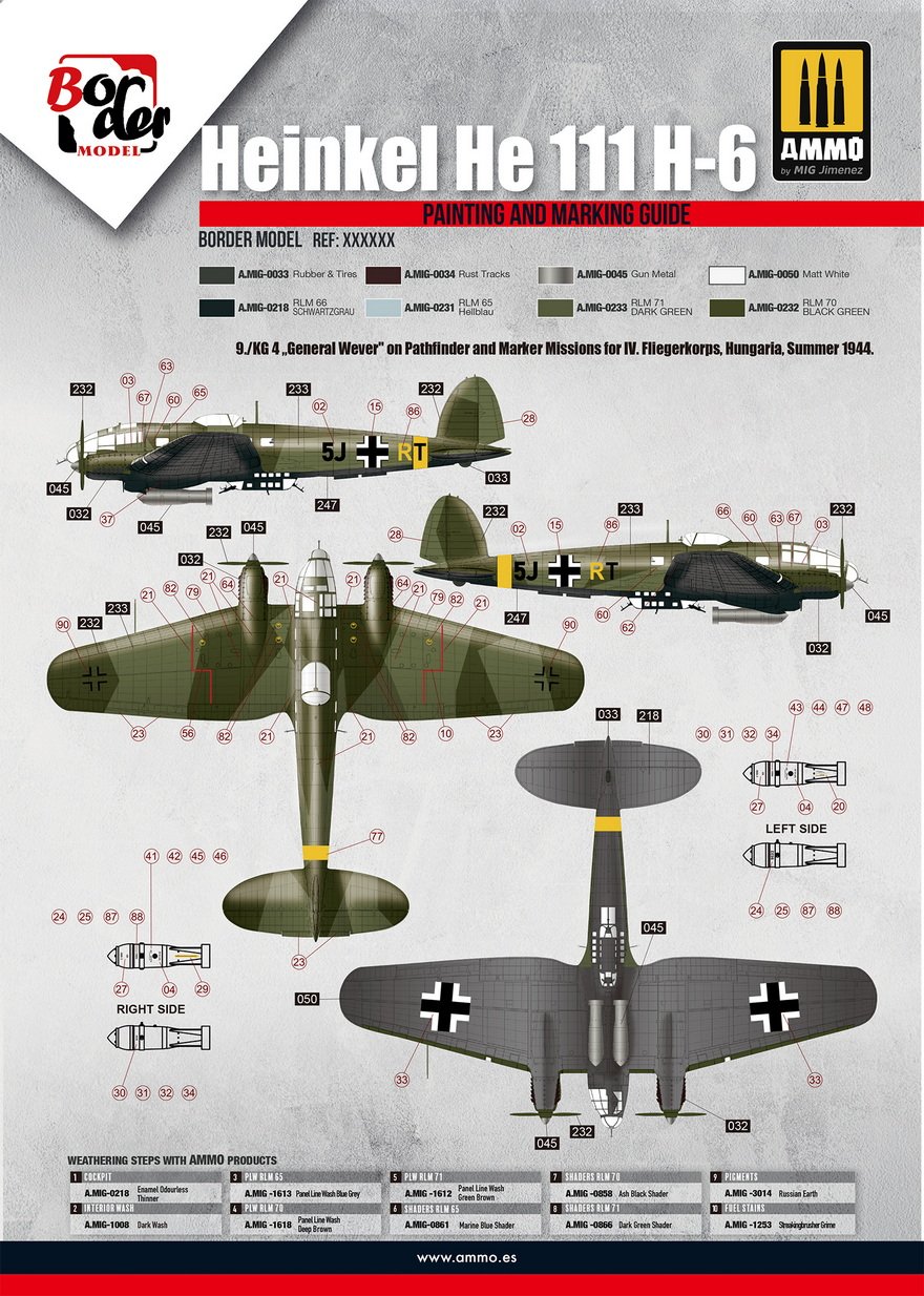
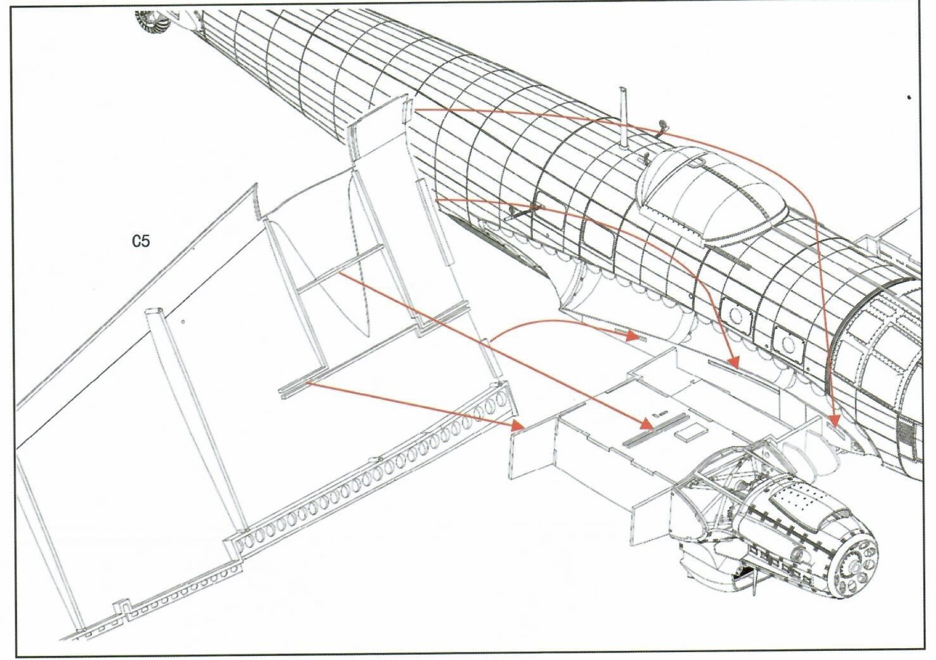
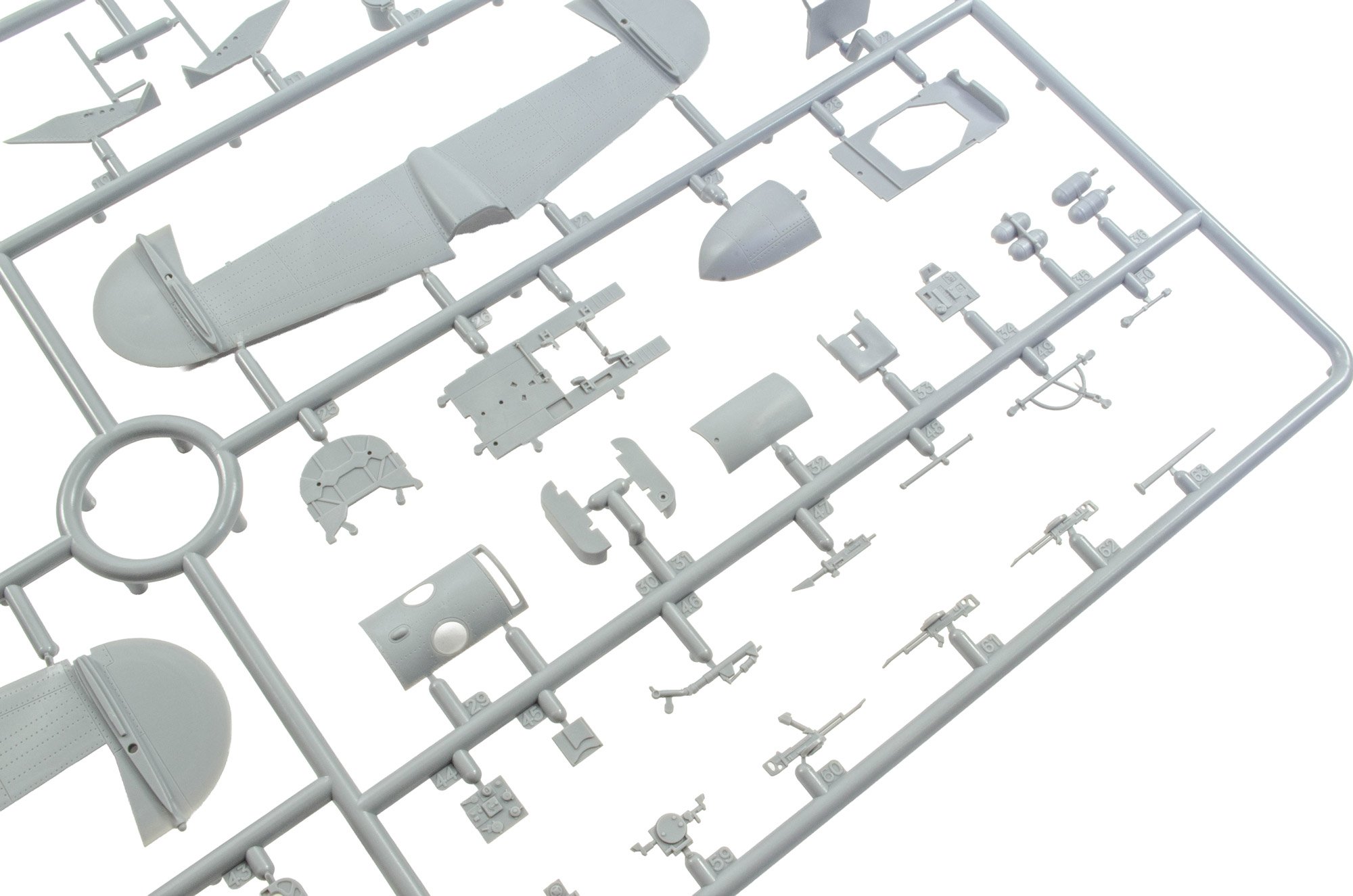
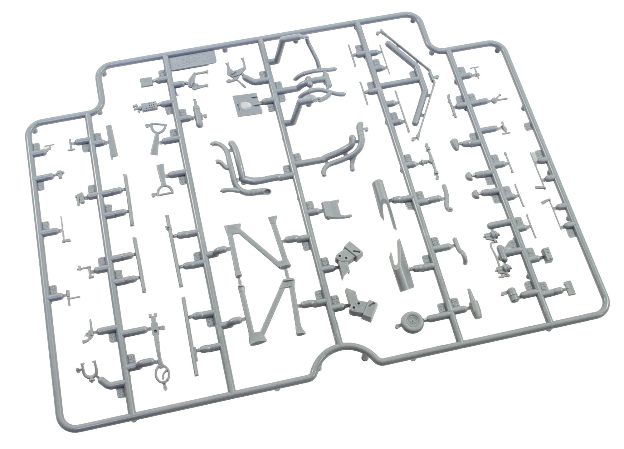
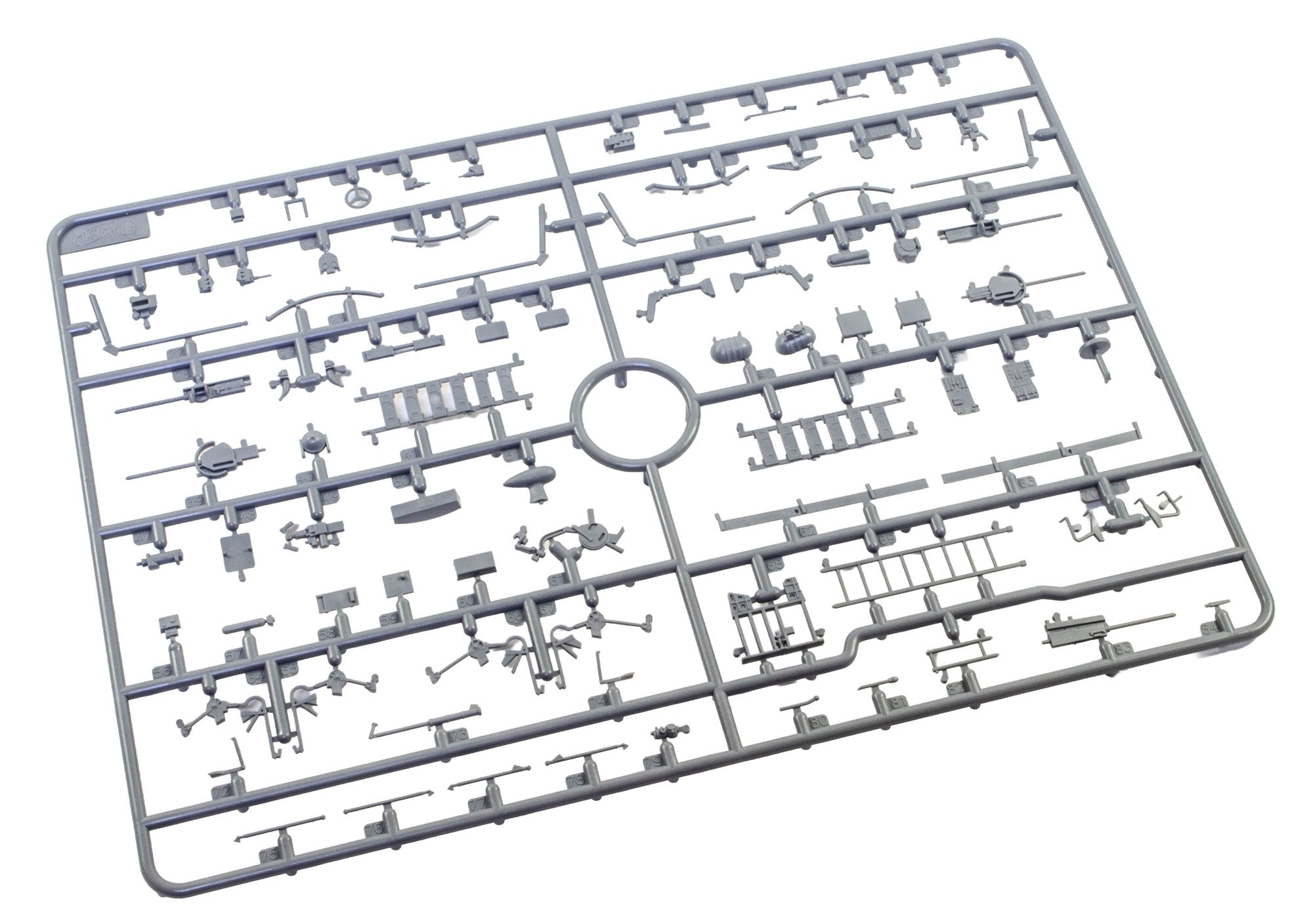
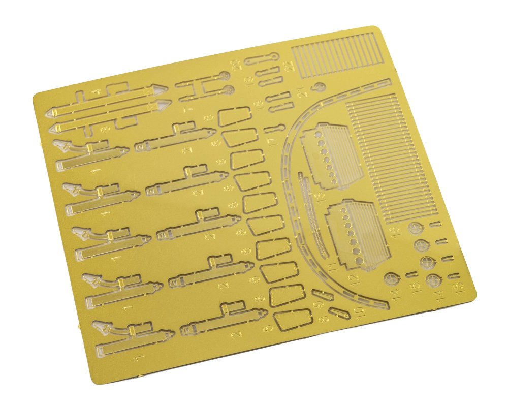
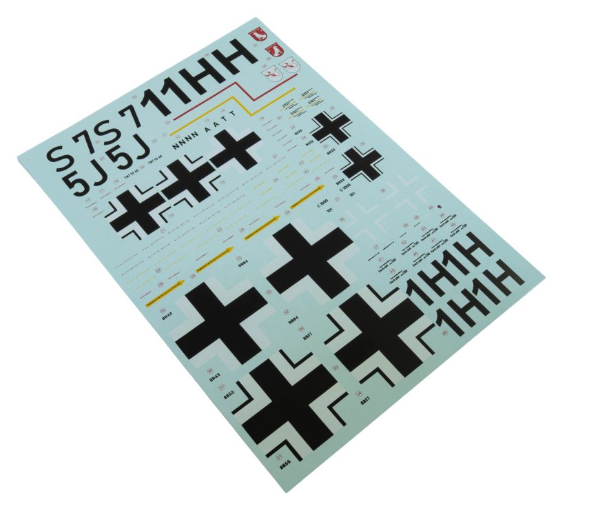
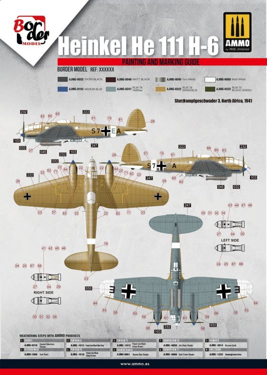
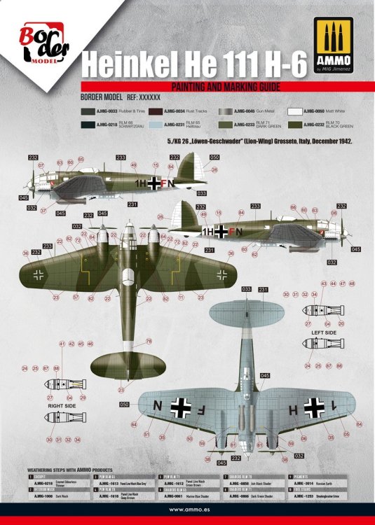
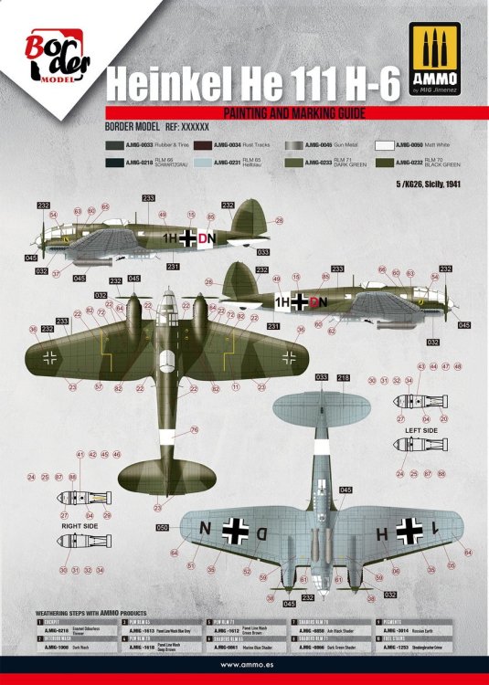
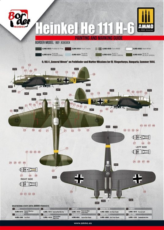
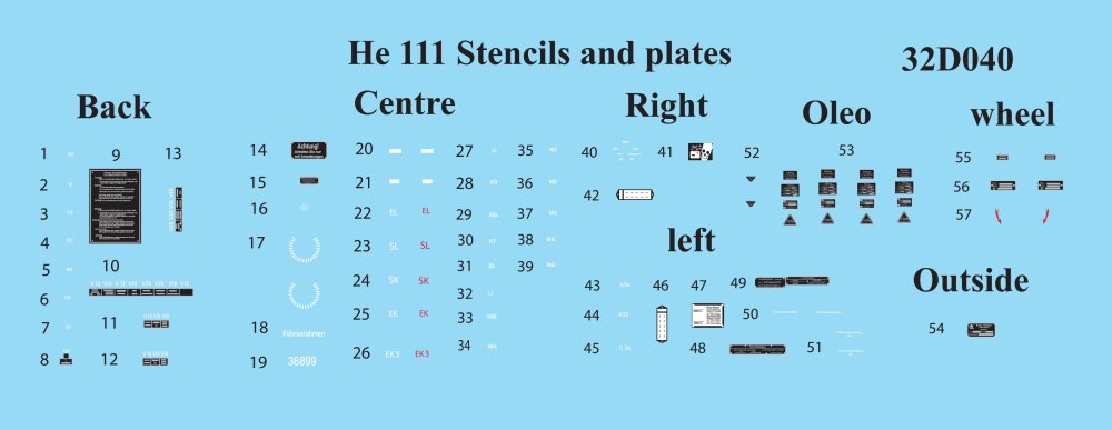
SPRUE Q This is very much a sprue for weapons (with the odd exception), with plenty of slide moulding in evidence. Photo-etch A single fret of PE is included, containing seatbelts, some glazing internal structure, and also parts for the cockpit and torpedoes etc. All appears to be good quality, although I will see what I can source in 1:35 for replacement seatbelts. I've never been a fan of metal ones. Decals and colour profiles FOUR schemes are supplied in this release. These are: Sturzkampfgeschwader 3, North Africa, 1941 9./KG 4 „General Wever" on Pathfinder and Marker Missions for I. Fliegerkorns, Hungaria, Summer 1944. 5/KG26, Sicily, 1941 5./KG 26 „Löwen-Geschwader" (Lion-Wing) Grosseto, Italy, December 1942. TWO decal sheets are included. Printing is nice and thin and with minimal carrier film. Registration is excellent too. I've no idea who printed these, but I can't see any potential issues. Swastikas are included too, supplied as halves in order to satisfy the requirements of some countries. Colour call outs are given for Ammo paint, but it'll be easy enough to determine the colours needed from other manufacturers. Instructions The manual is a 48-page, full colour tome, albeit with the construction sequences generally in black and white line drawings, with some annotation given for various parts options. There has been some consternation about the clarity of the drawings, and having spent some time with the manual from an online source, I can understand what folk are saying. Some illustrations seem a little muddy in relation to parts fitment. I wish someone at ICM had created this manual for them! You will need to do plenty of forward working and test fitting to ensure you get everything correct. Just take your time. A parts map is included, as is a full colour chart for Ammo paints, and a whole page each for the colour schemes, as shown previously. Some of the construction sequence is quite unique to this release, such as adding the engines to the wing frame, and having those delicate structures in situ while manipulating larger parts like wing panels. Conclusion Well, what can I say? This is a superb release and encompasses everything about scale modelling that attracts my attention. I know, it’s not 1:32, and a lot of aircraft modellers feel uncomfortable stepping away from the recognised scale, but face it, it’s unlikely we’ll see Revell re-pop their 1:32 kit anytime soon, and compared with this kit, the Revell is very much lacking in both internal and external detail. I’ve seen a few Revell kits being offloaded fairly cheap since this was announced. That scale disparity dislike perhaps isn’t as widespread as thought. From the oil canning, to the raised rivets, engineering breakdown, and sheer number of options, this release is likely to be many things to many people. I do think the canning is overdone, and the raised rivets raises a few eyebrows on an airframe which was likely flush riveted almost in its entirety. I might do a little surface rework on this when my time comes, but as I don't want to screw an entire project, I may build almost as moulded and treat the surface textures for what it is. Everything is a compromise, so this is just another one. No masks are supplied in this release, which is a real shame, although the manual has templates for those. I think I'll wait for there Eduard set though! My next project is the ICM Do 217K, but this will follow straight afterwards. My sincere thanks to Border Model for this stunning kit. To buy directly, click this Scalemates link and check the Marketplace section.


-
border model Border Model 1:35 Heinkel He 111H-6
JayDee replied to JayDee's topic in Aircraft Reviews
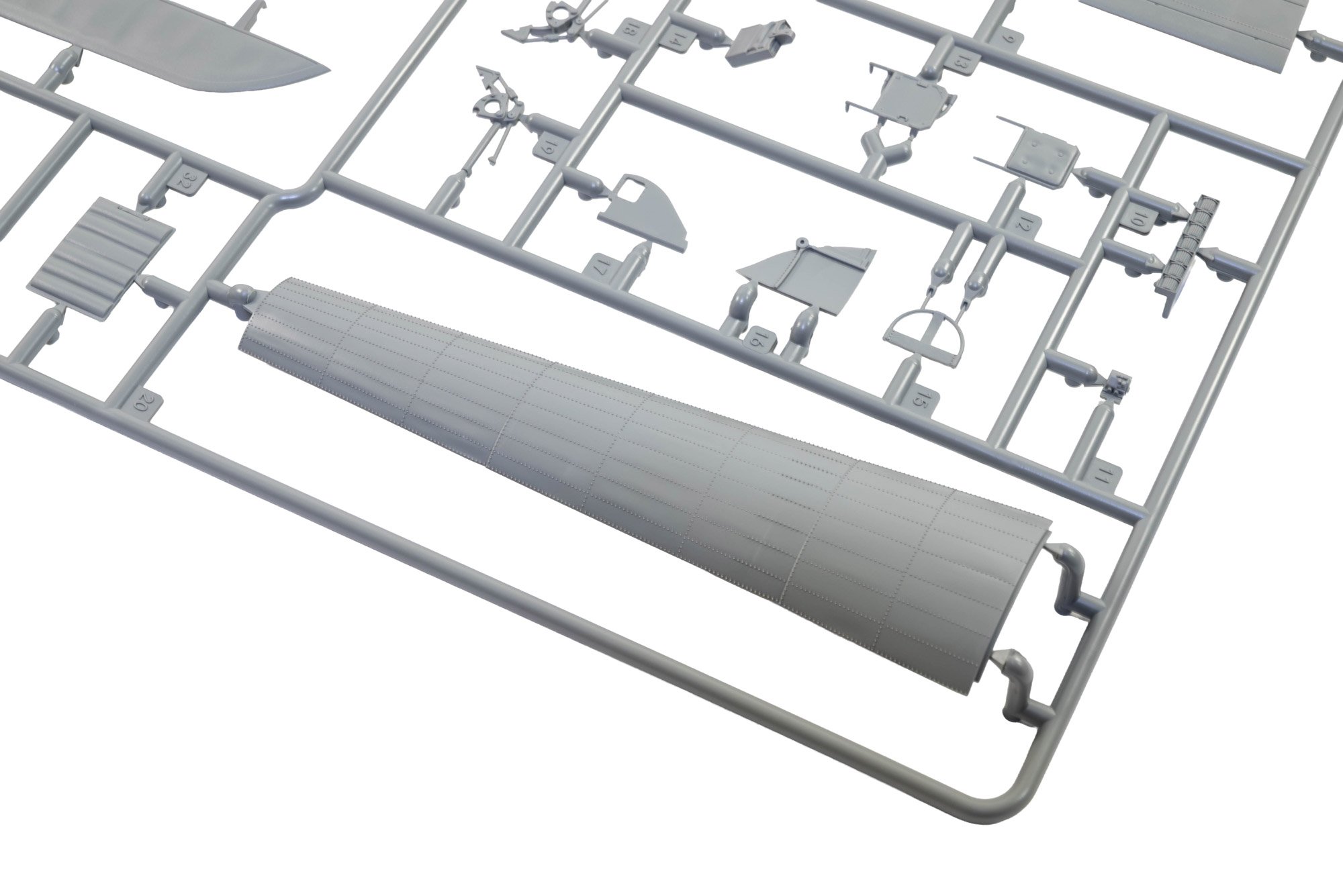
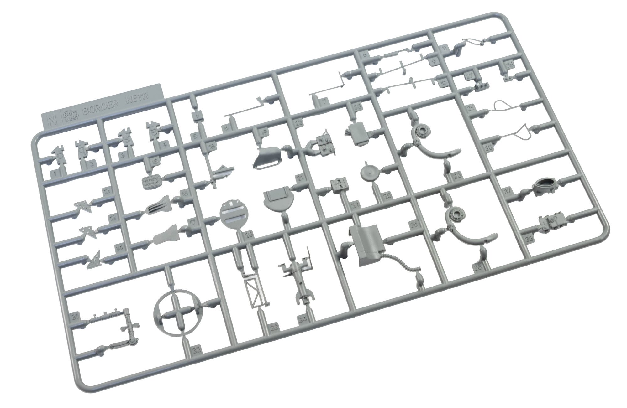
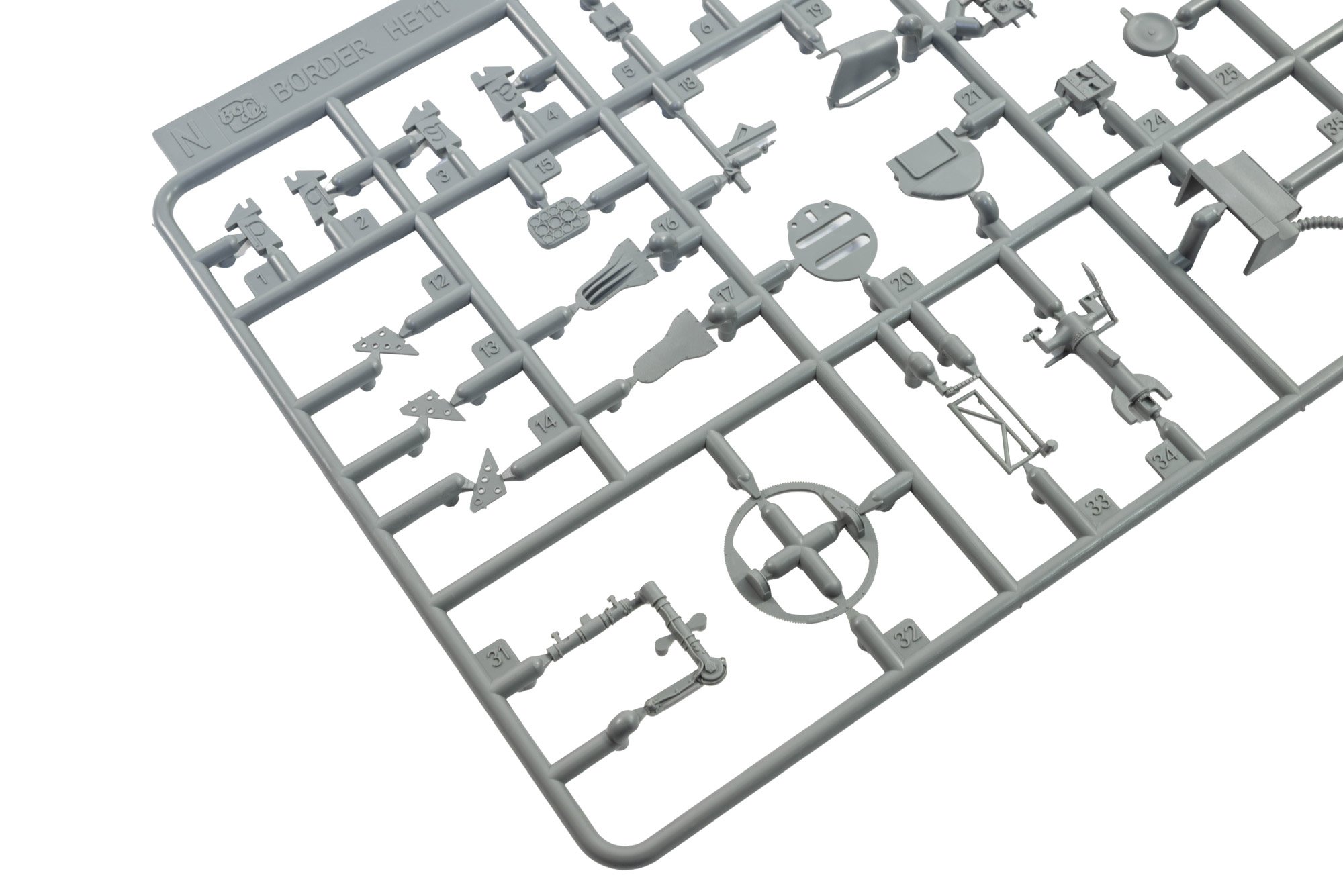
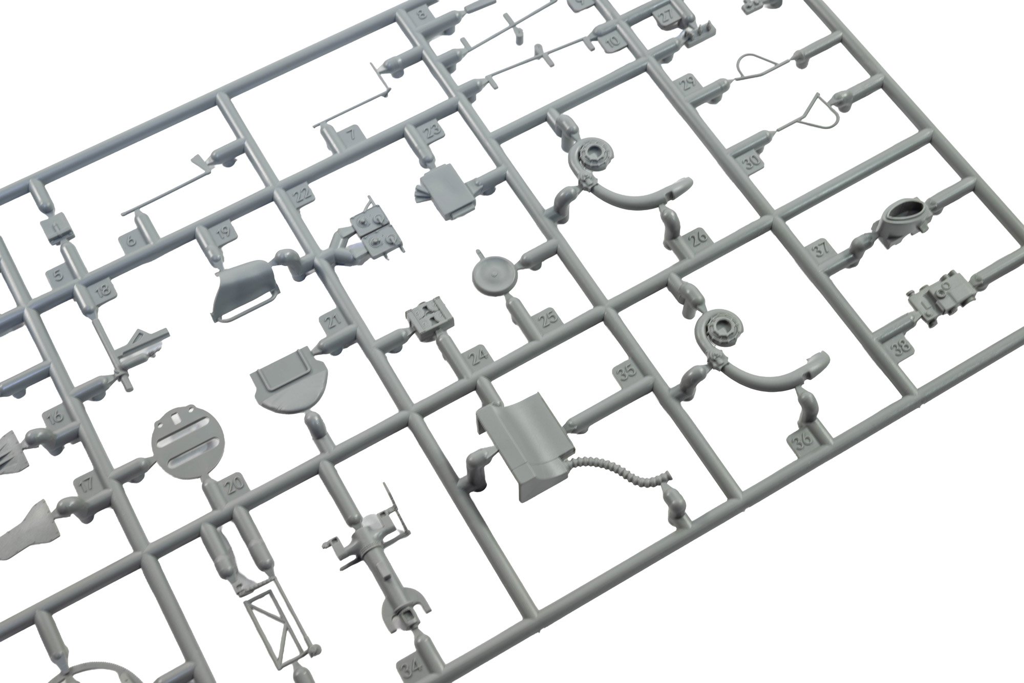
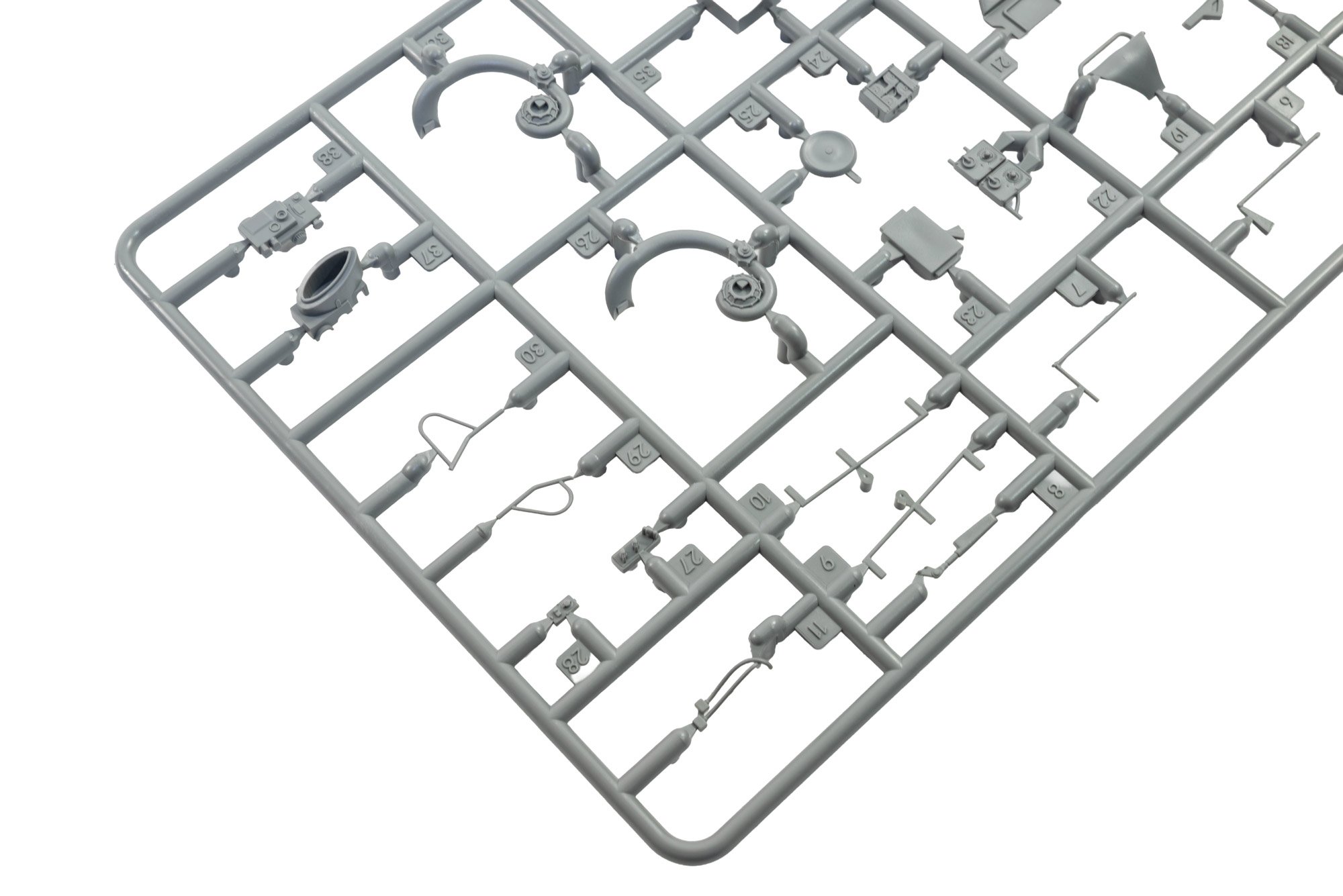
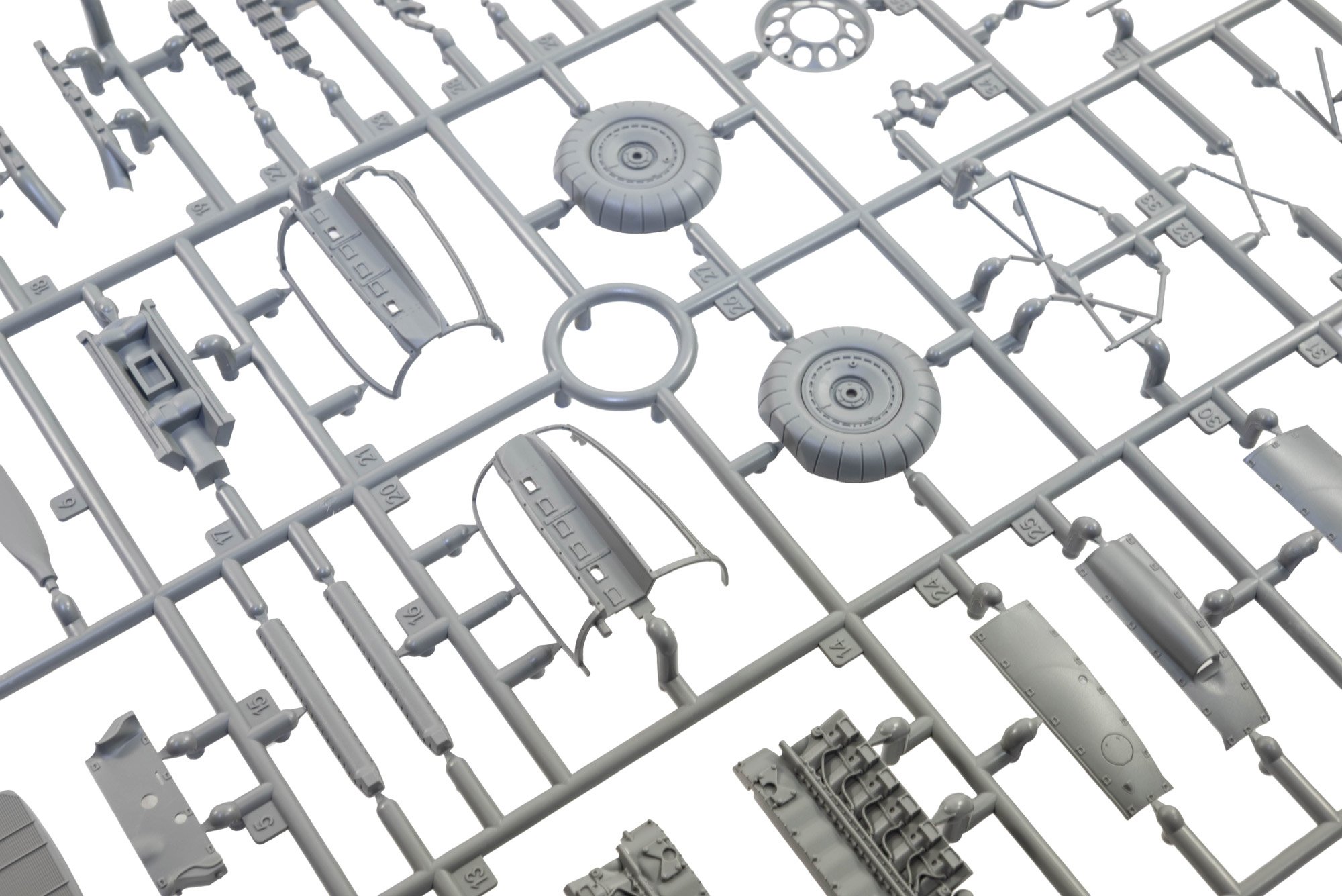
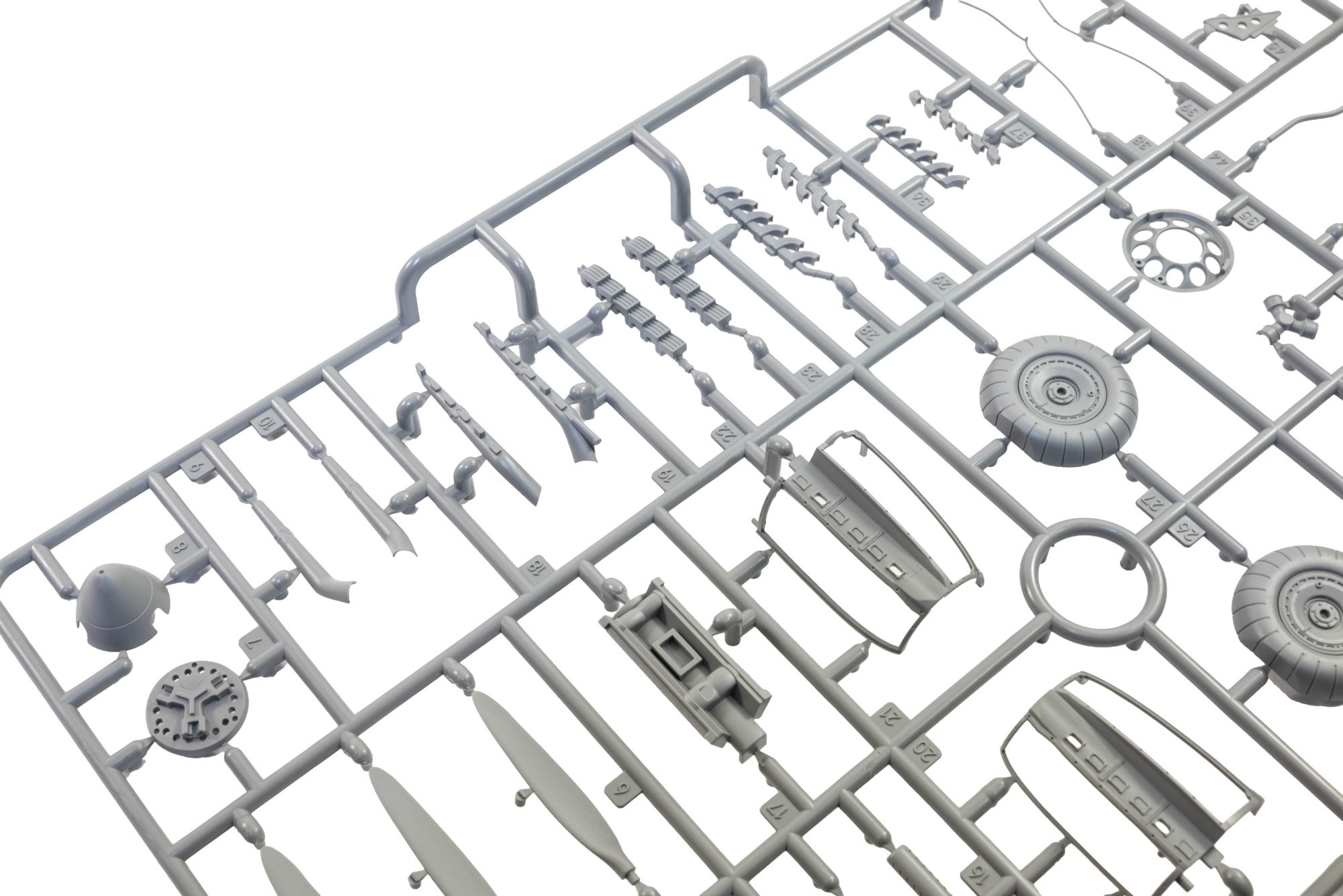
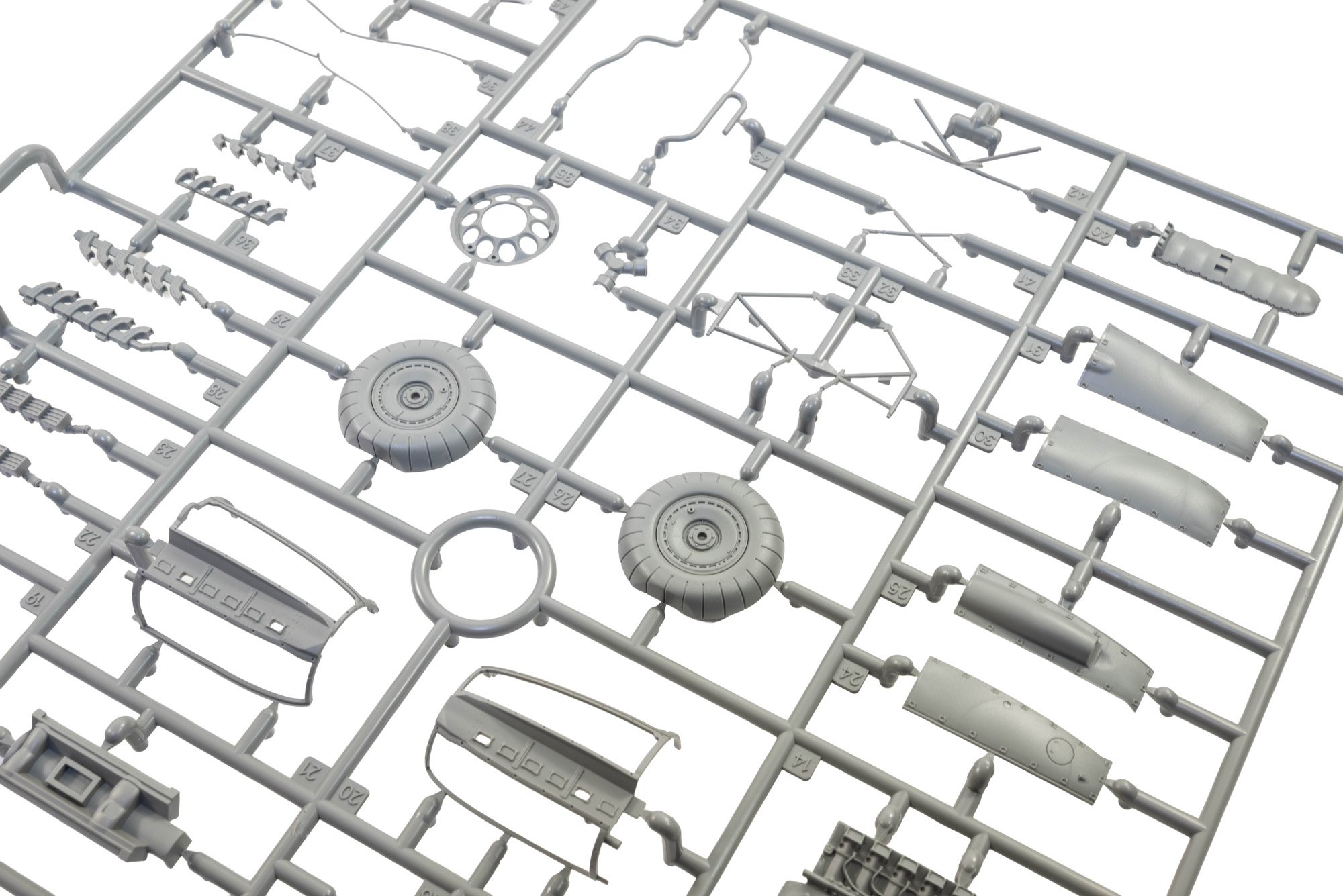
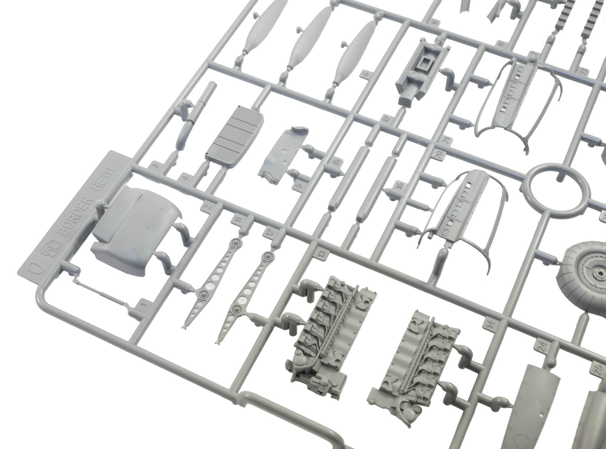
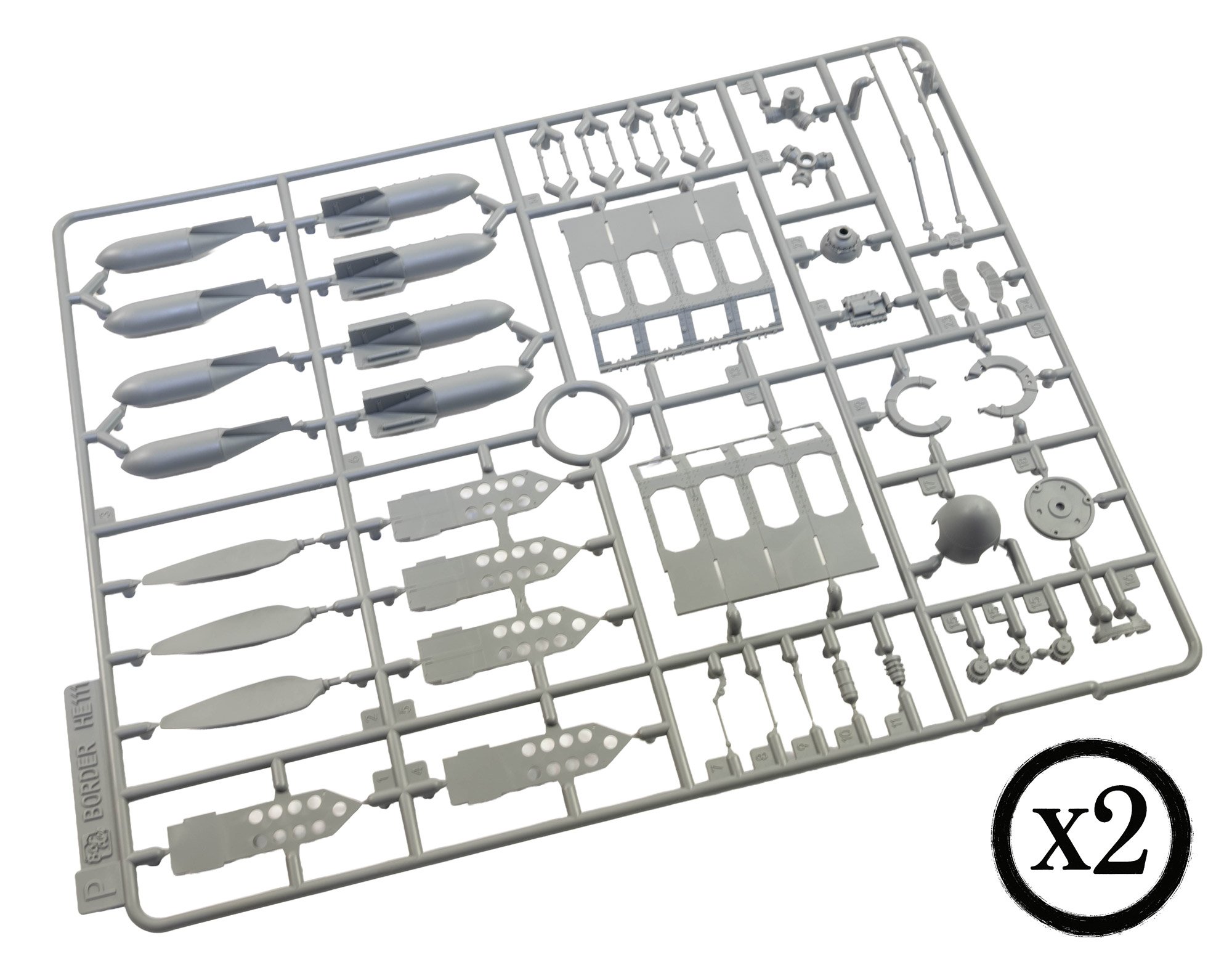
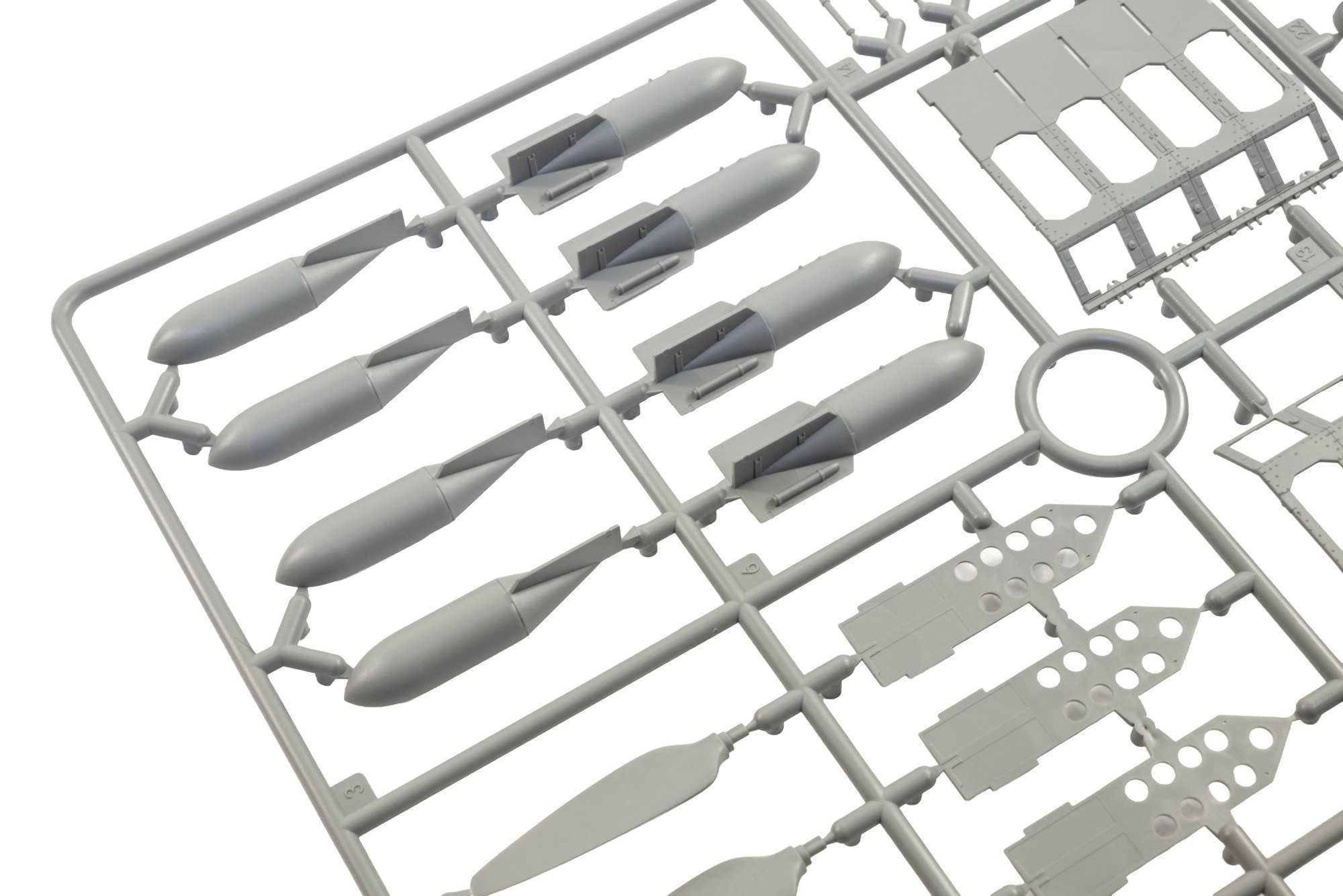
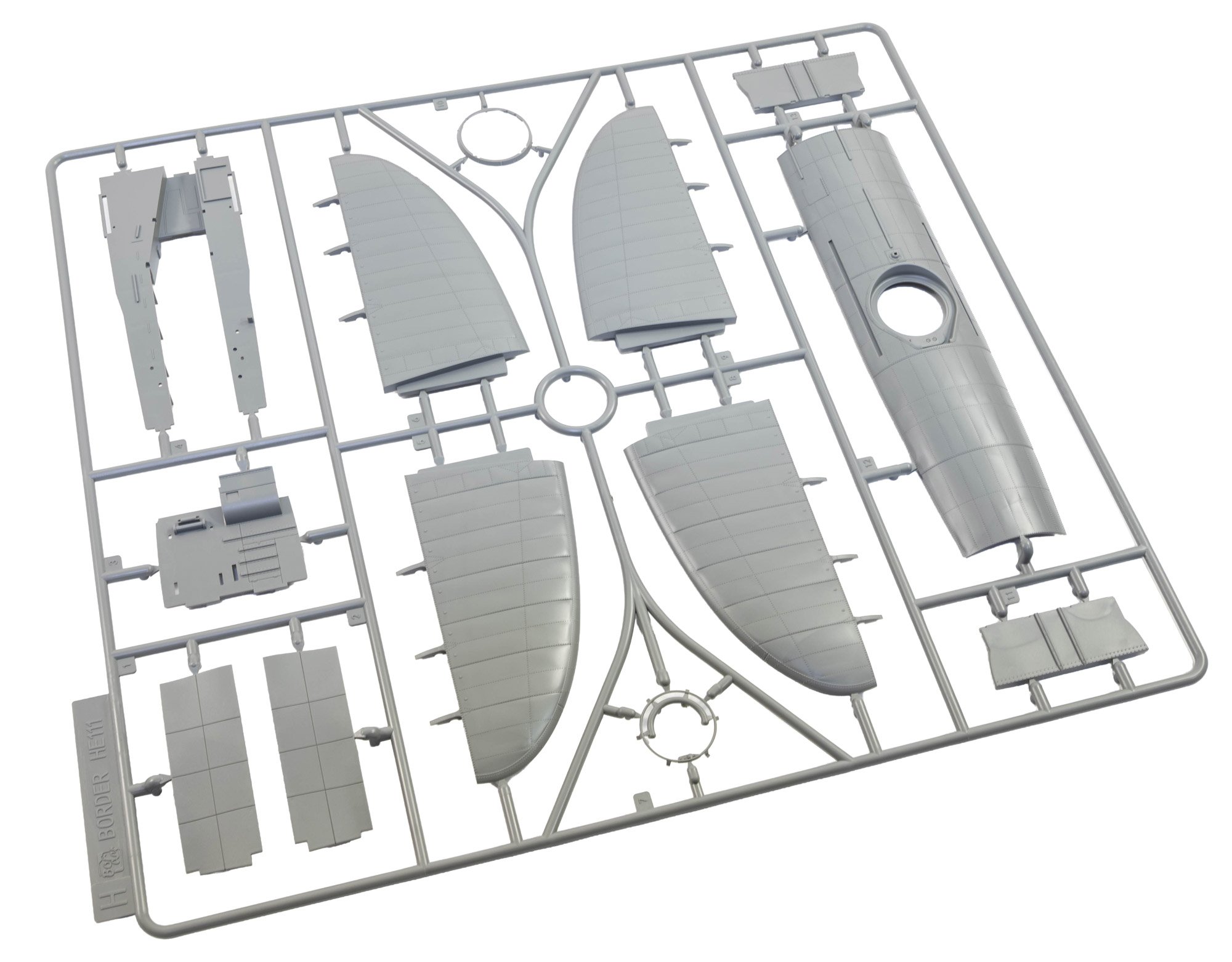
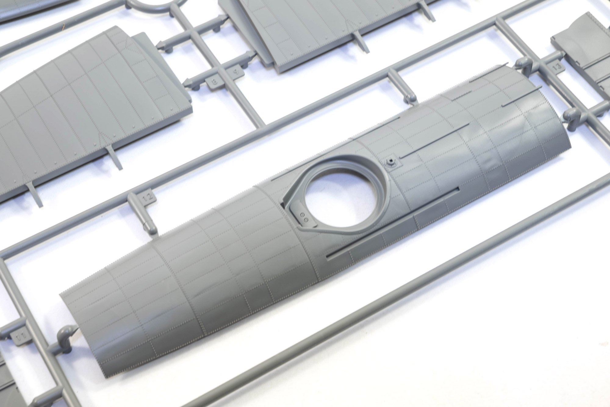
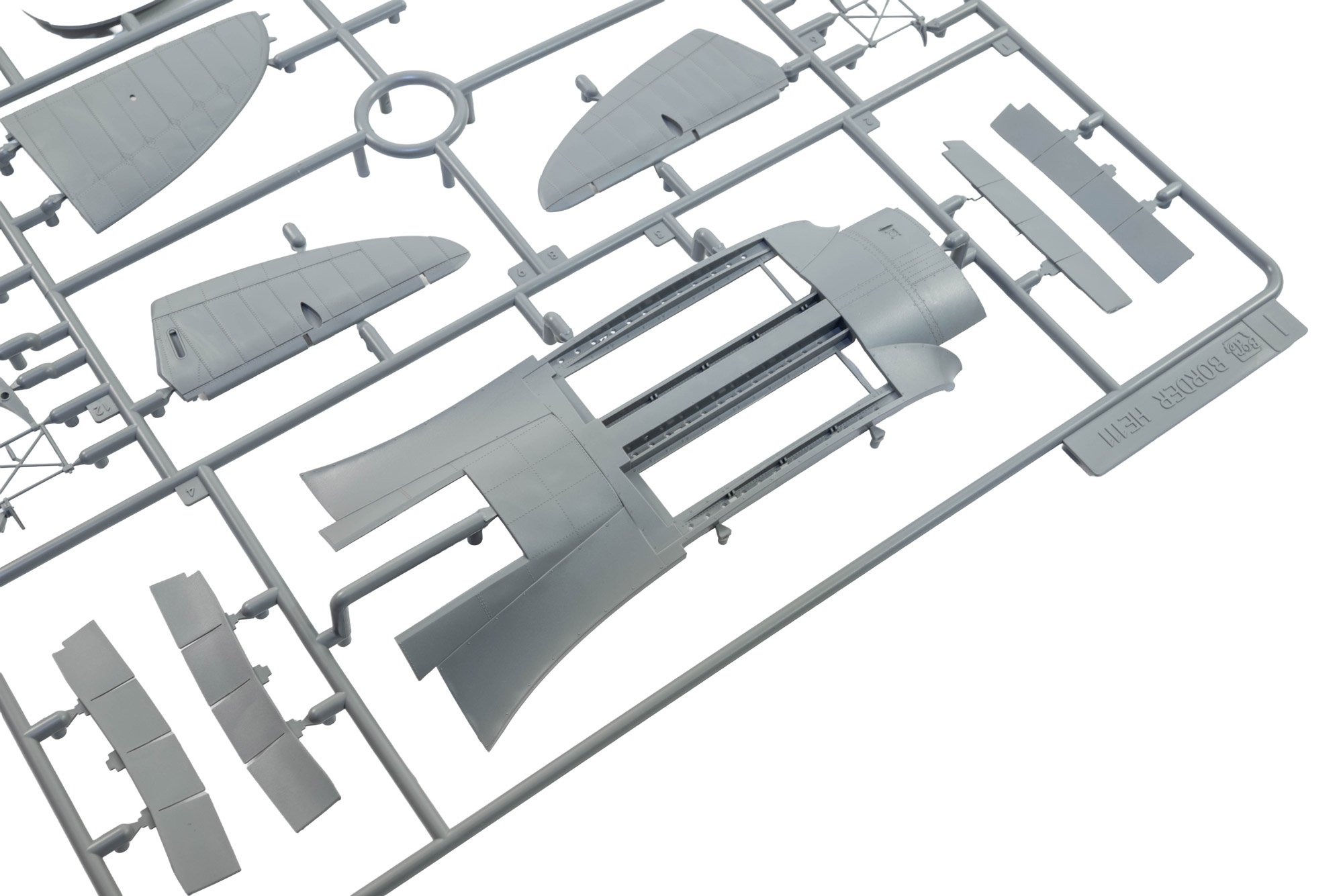
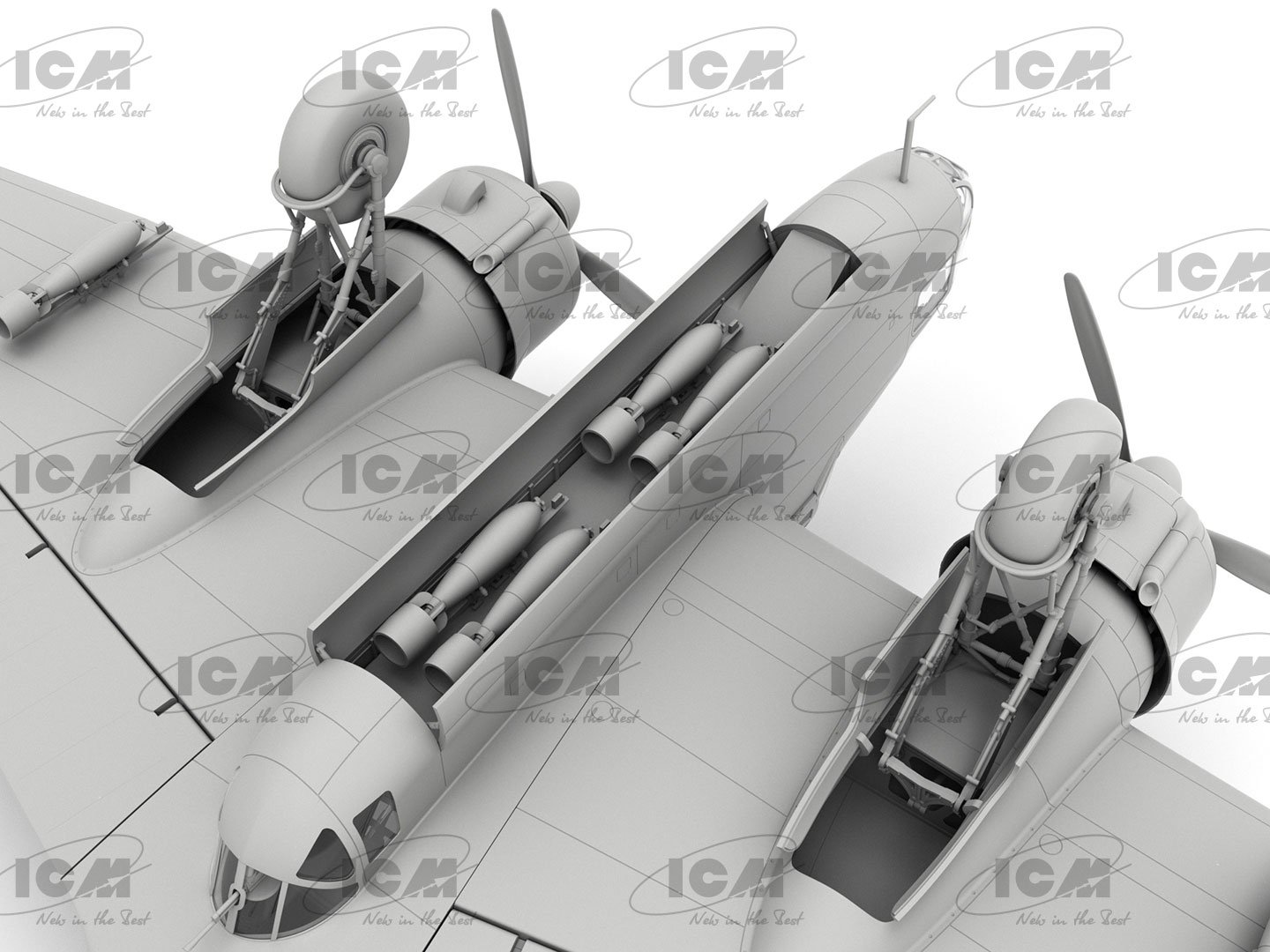
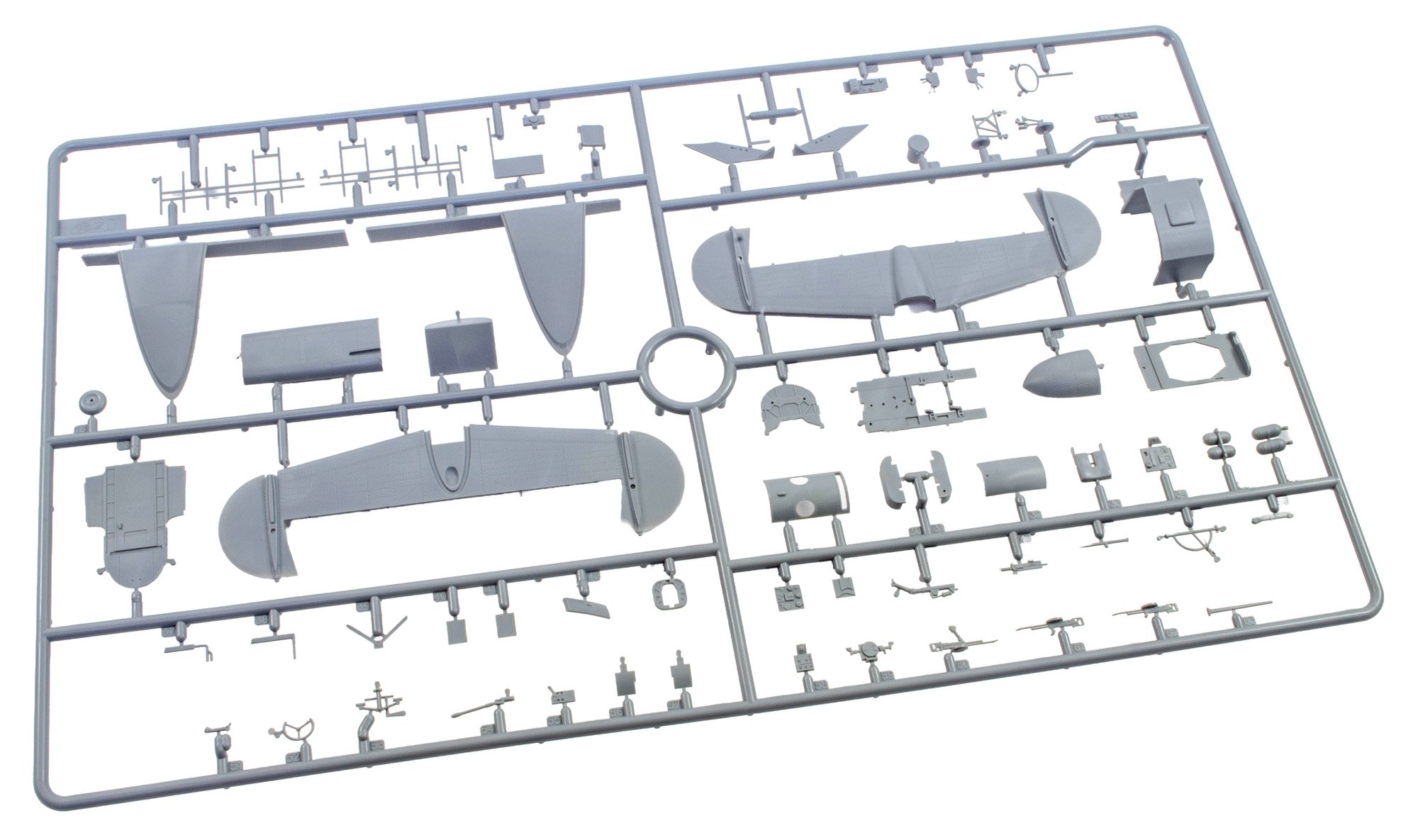
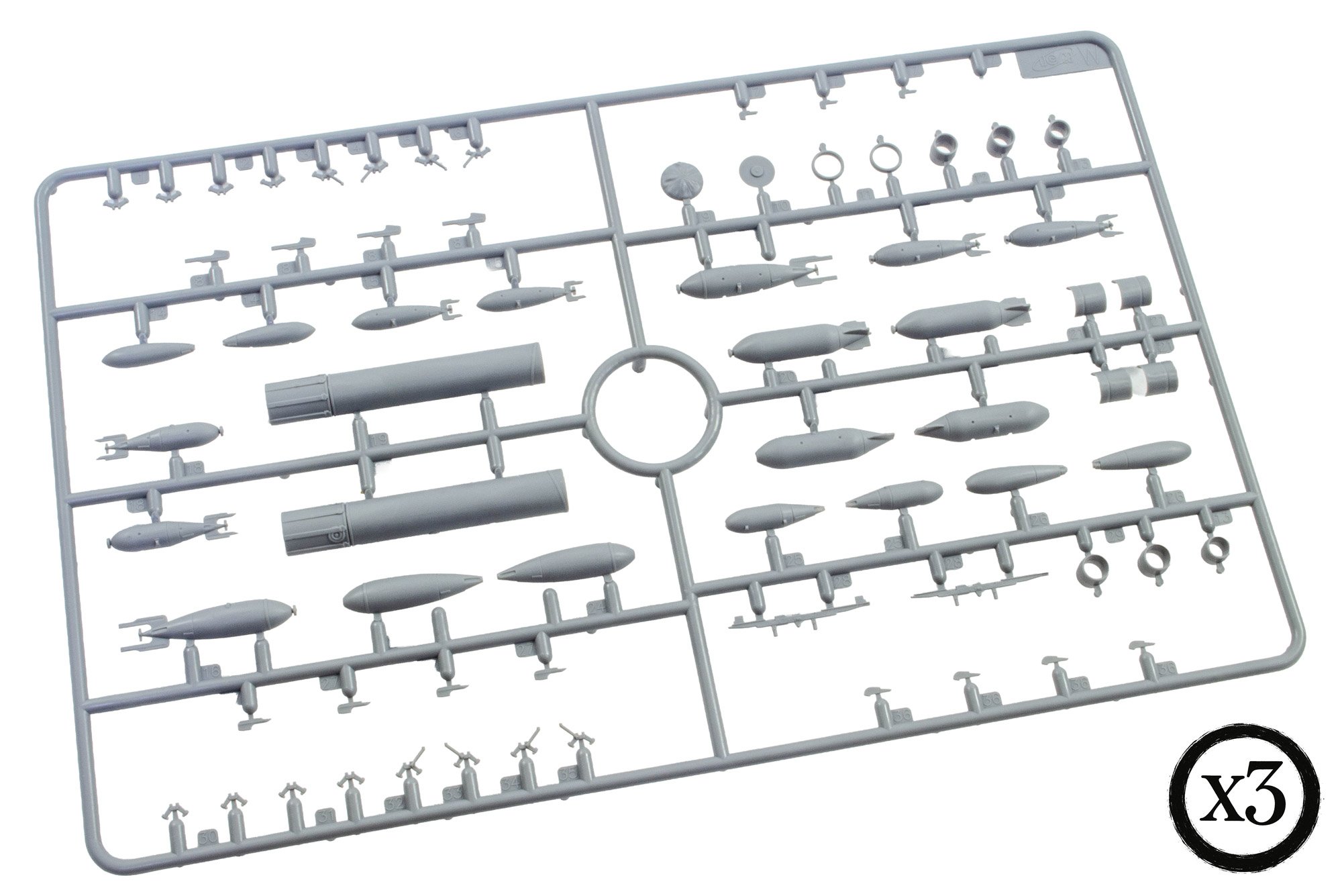
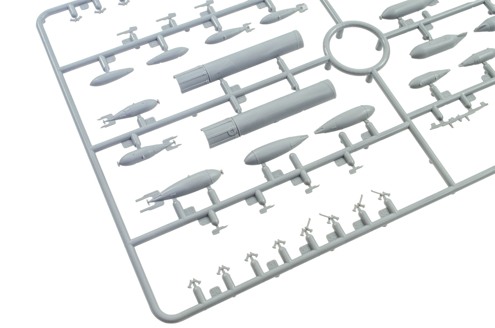
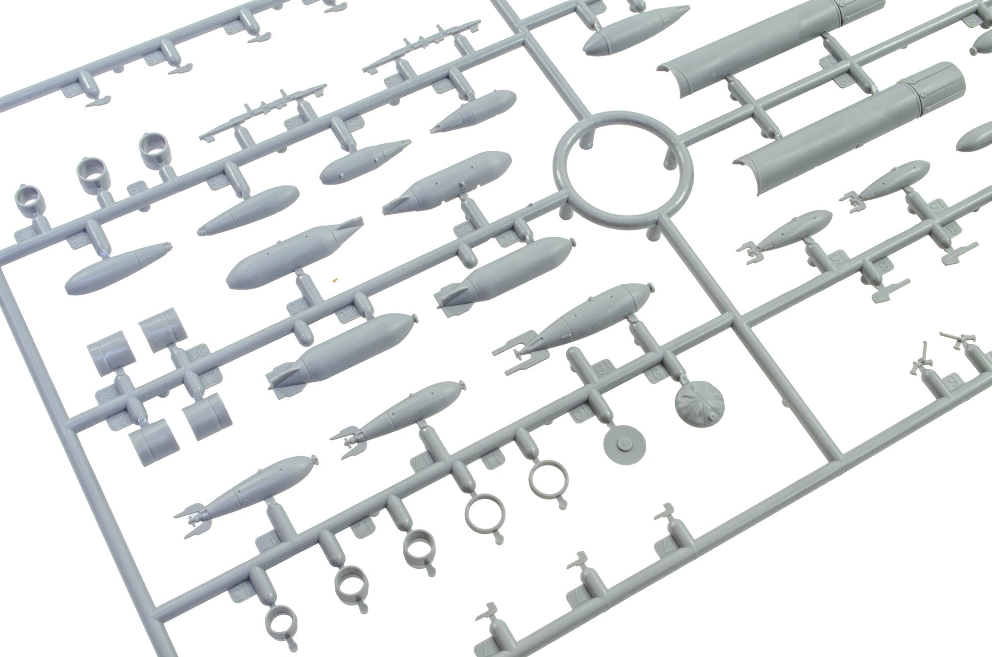
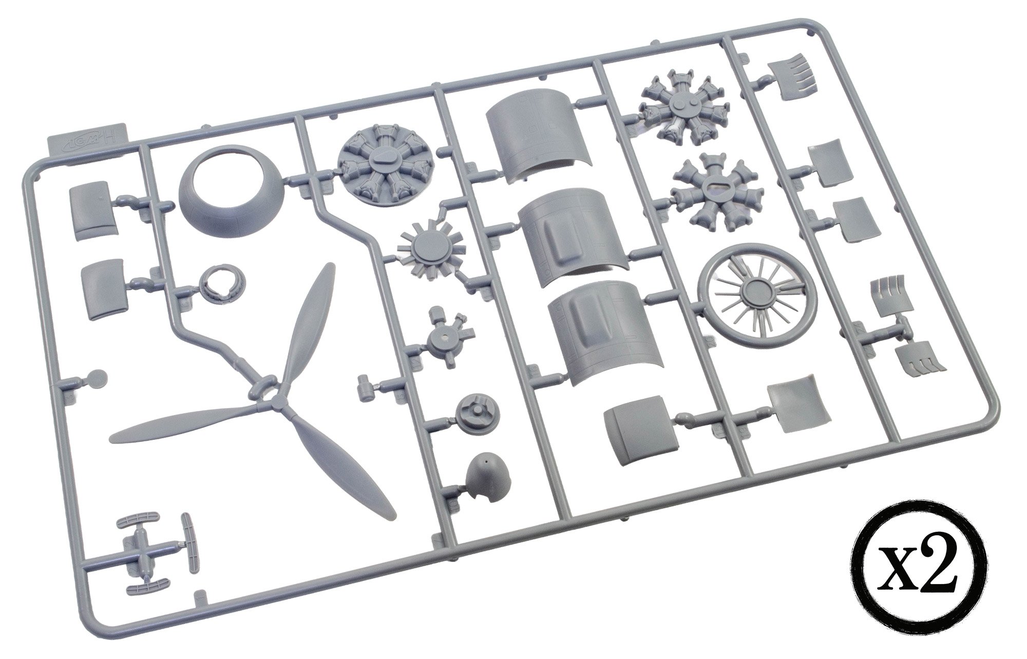
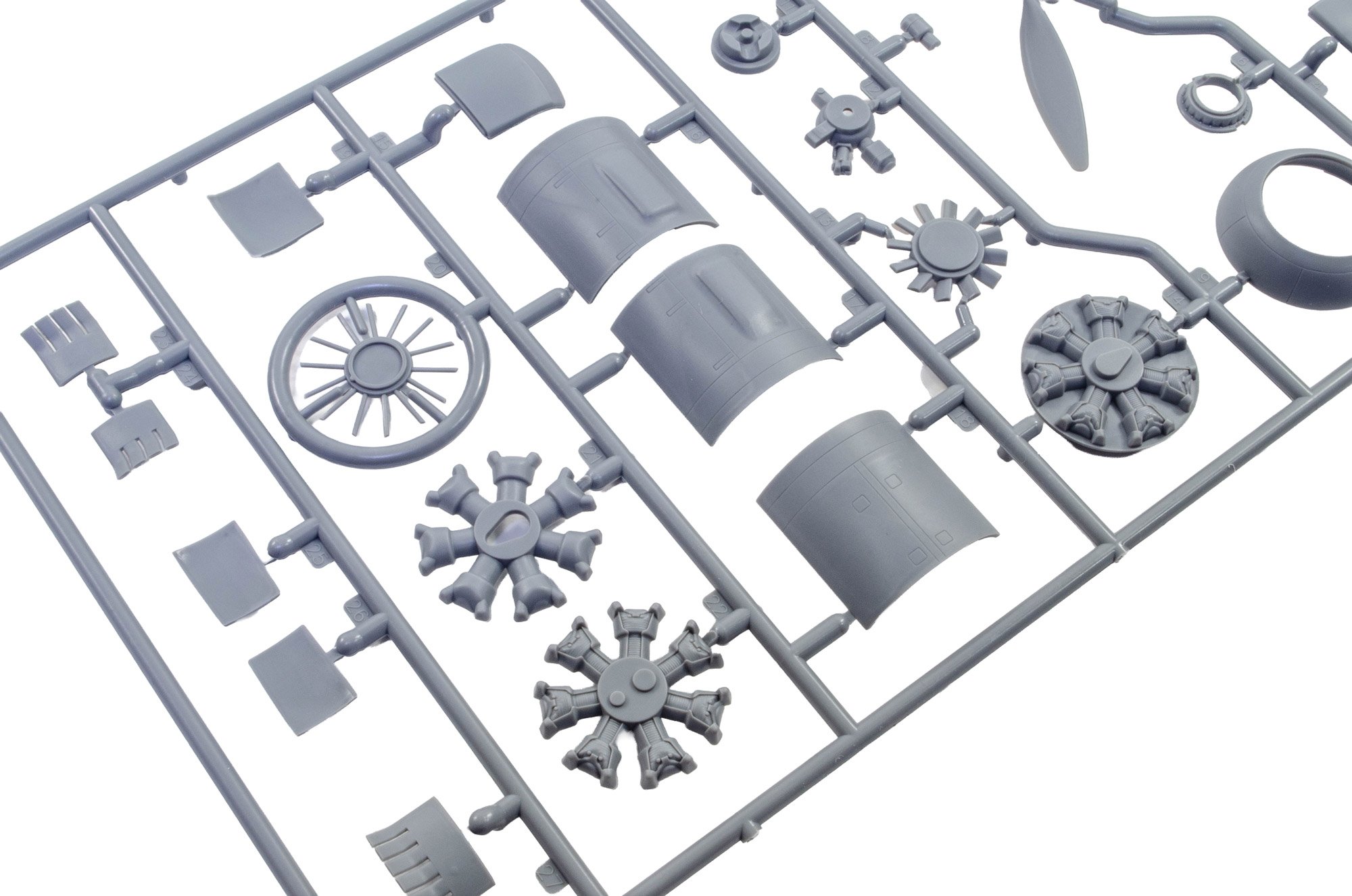
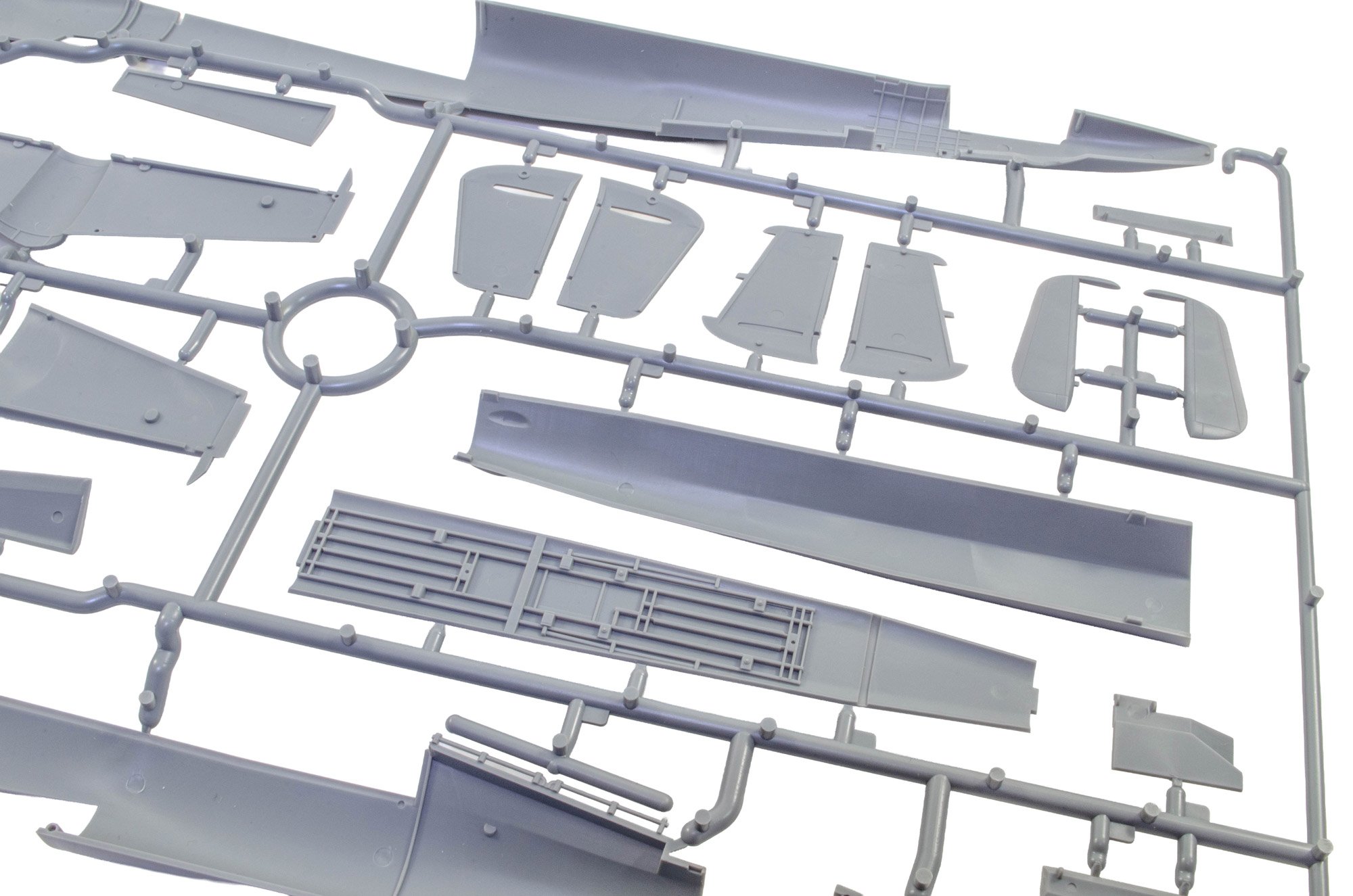
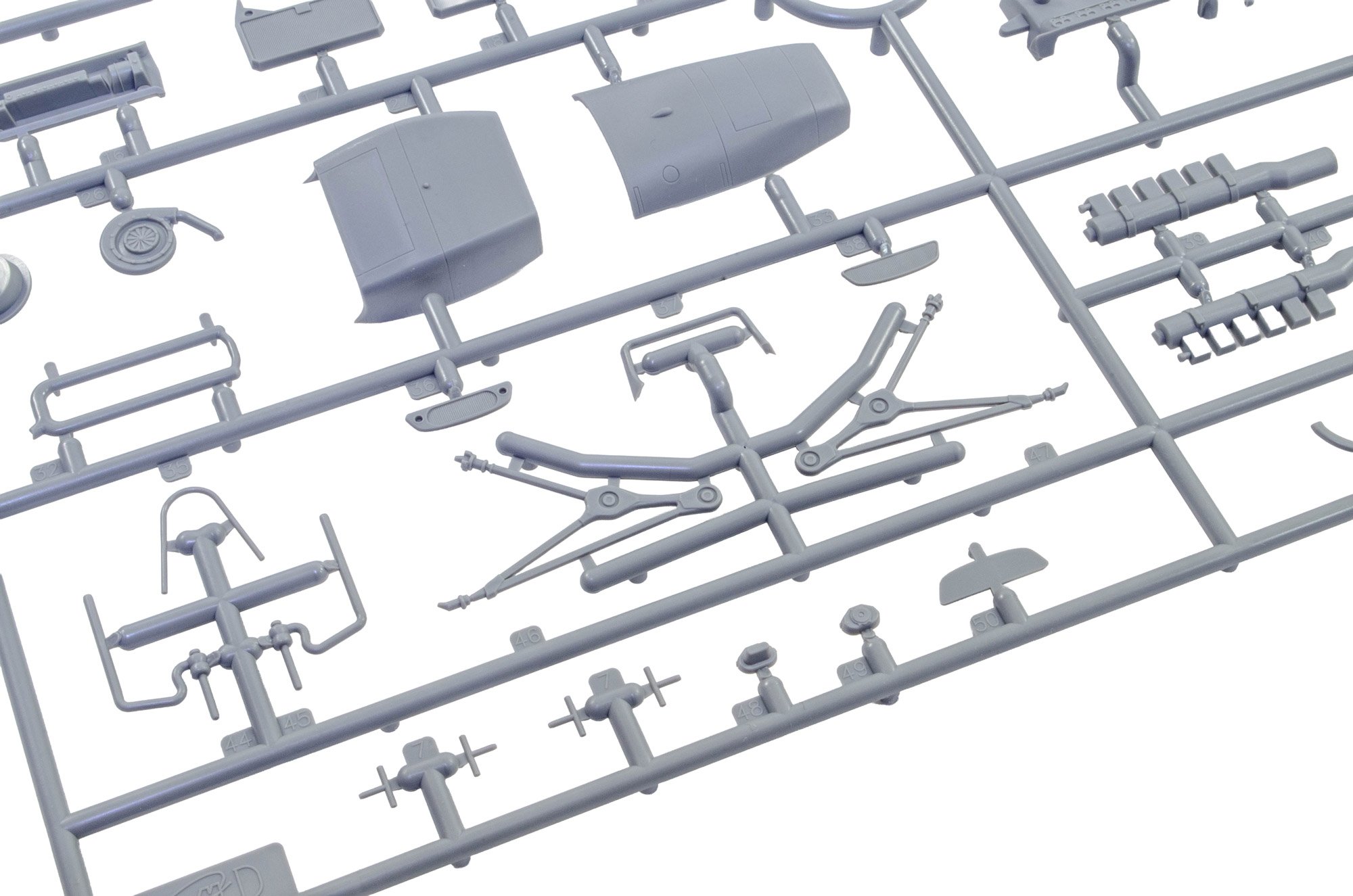
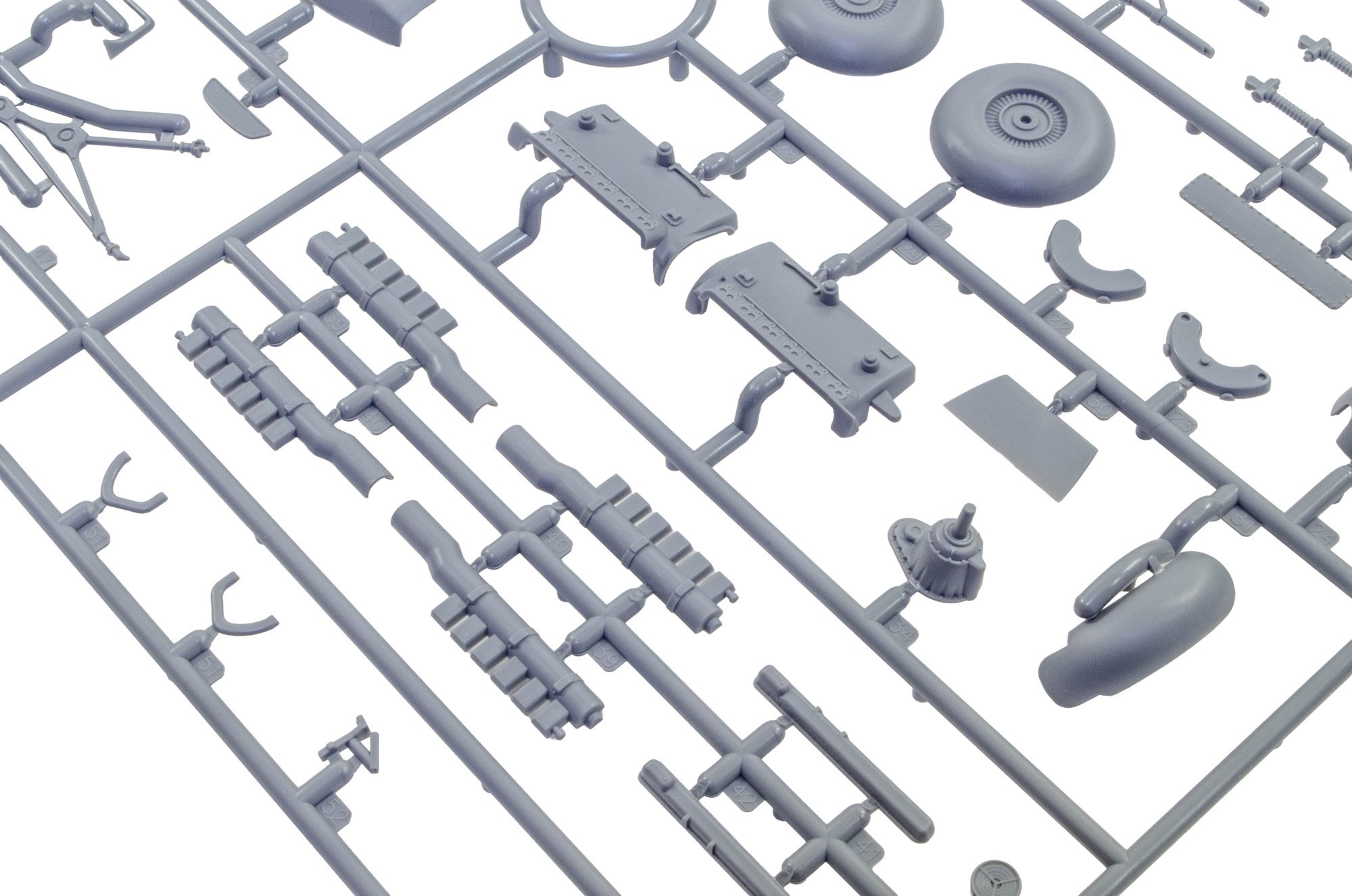
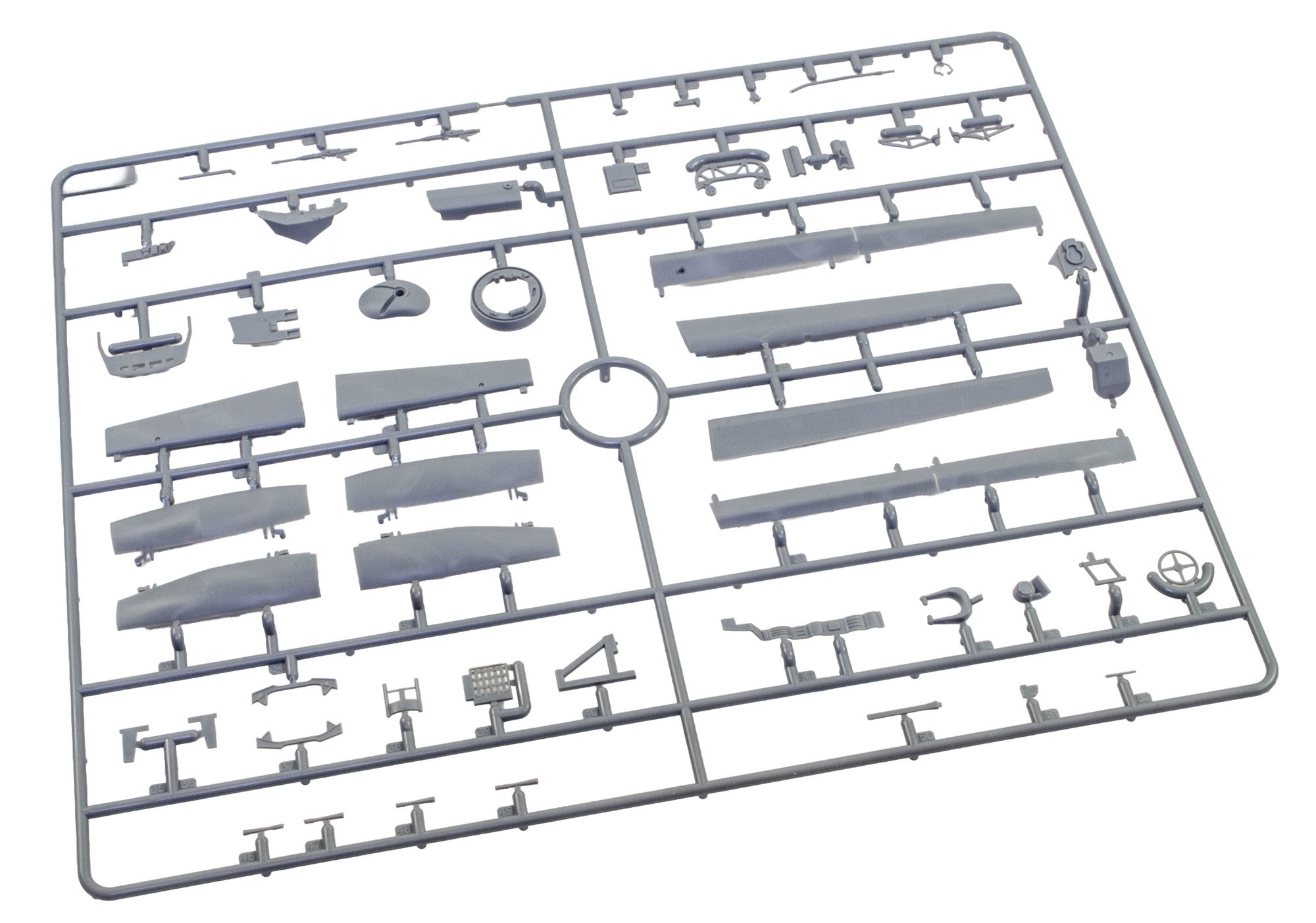
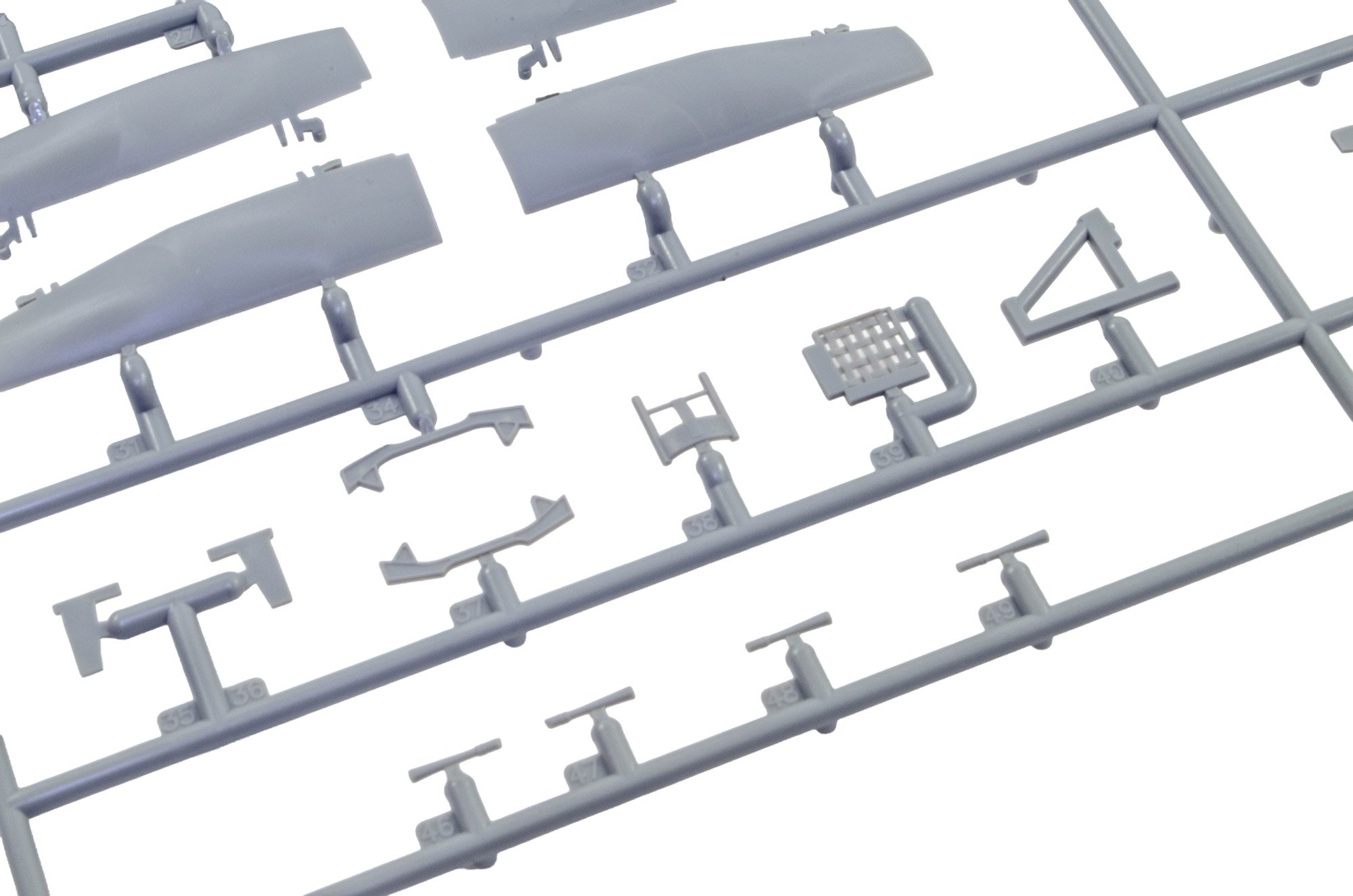
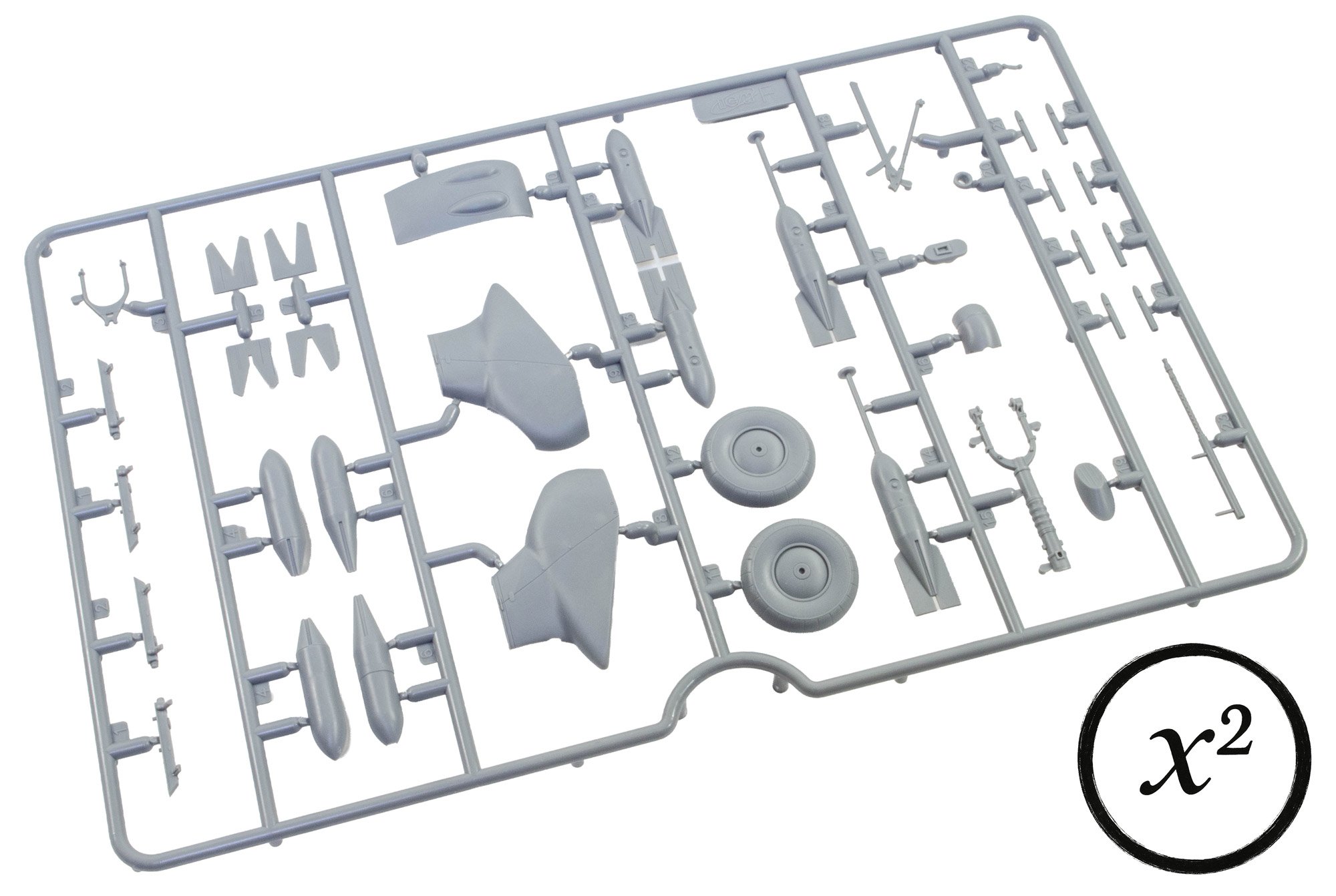
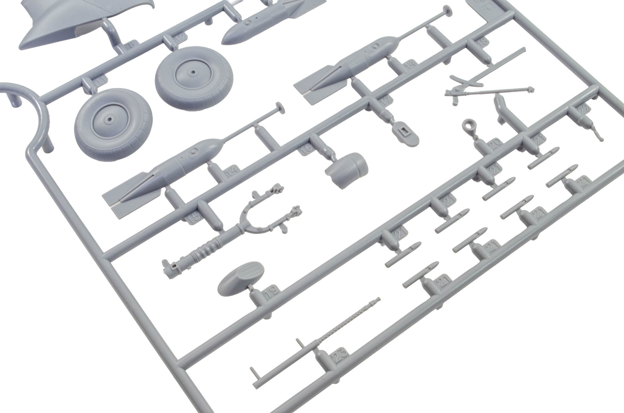
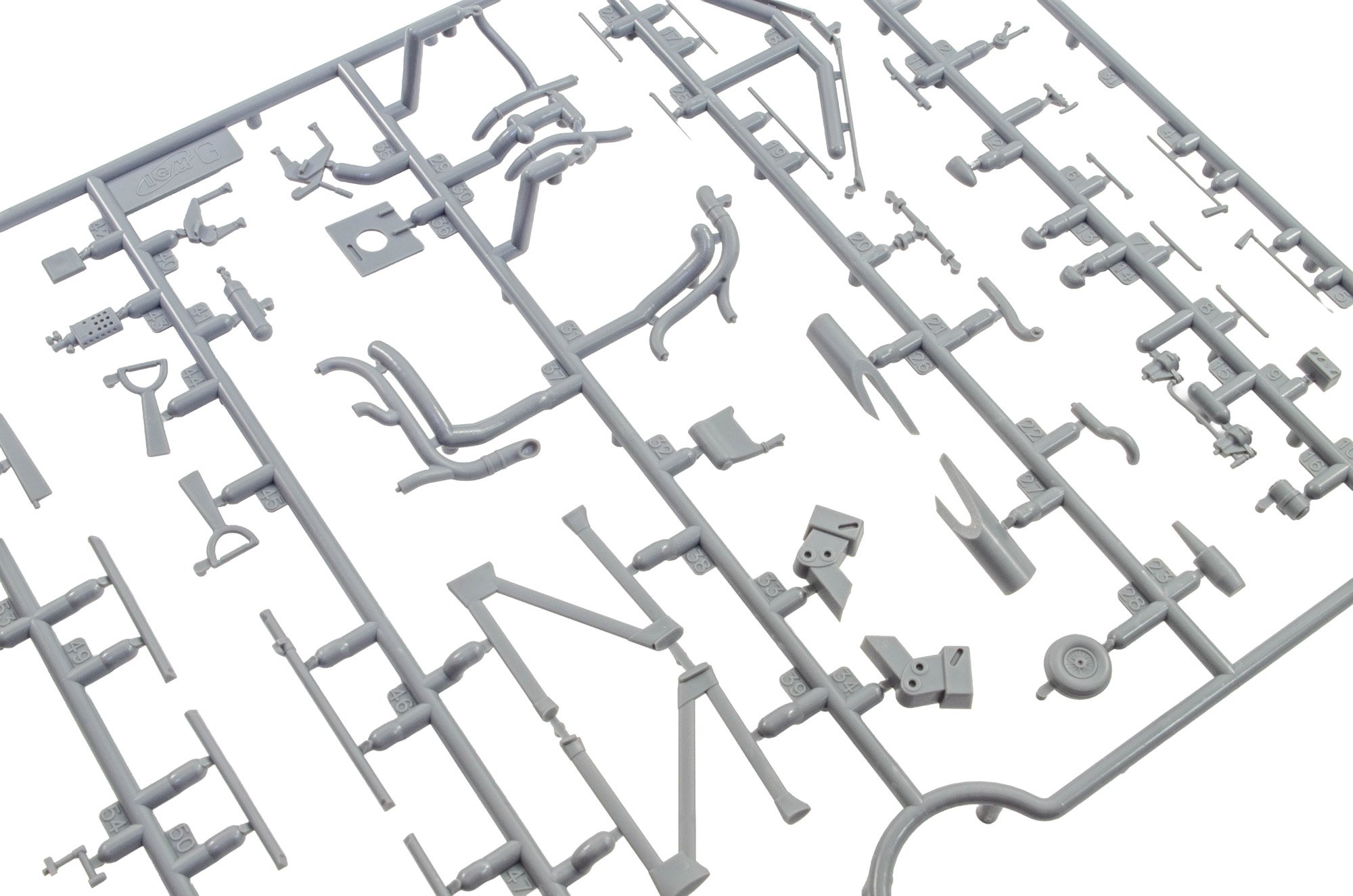
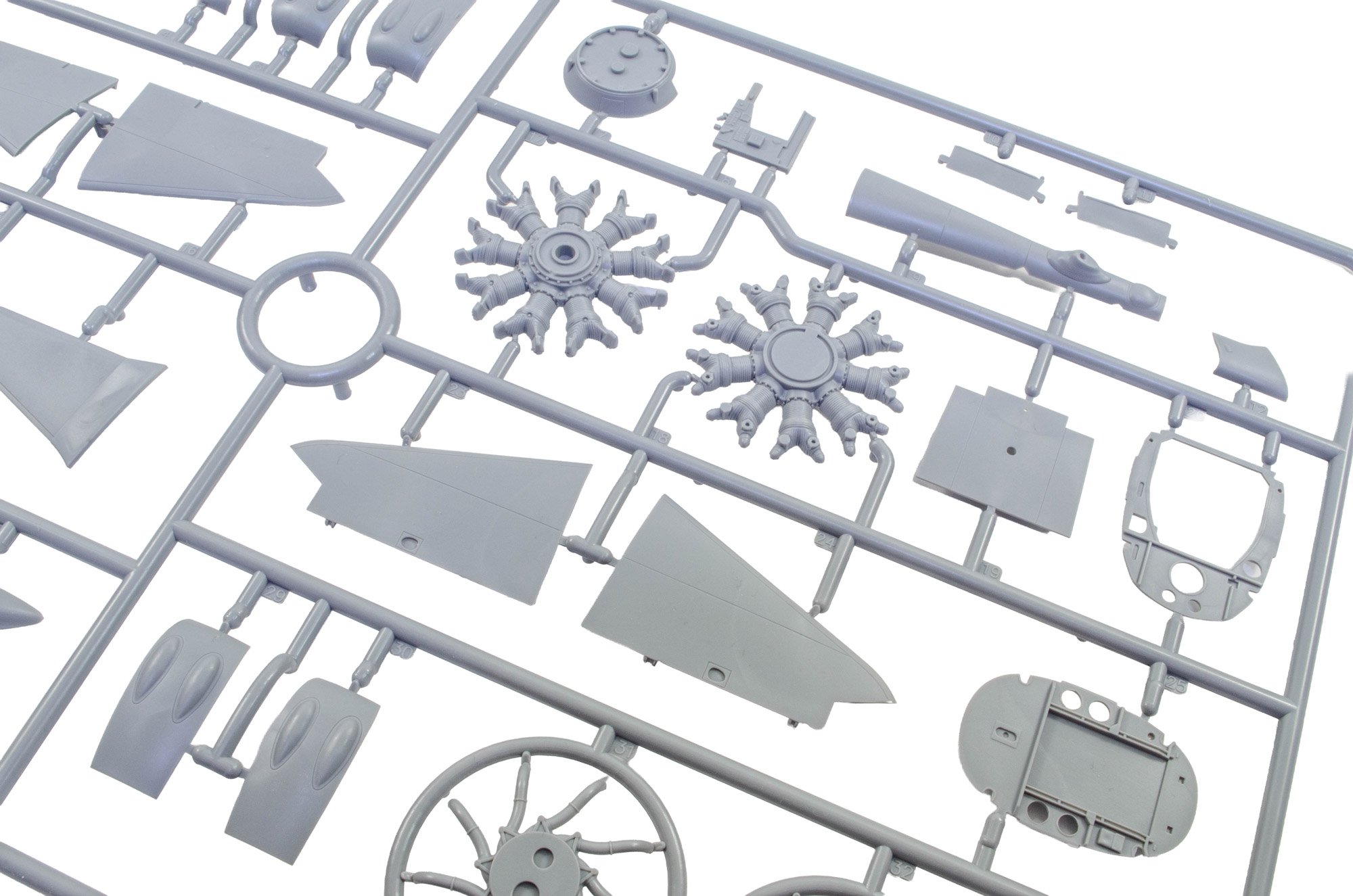
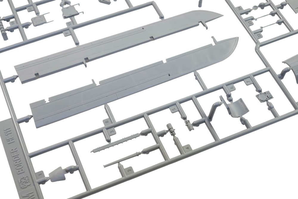
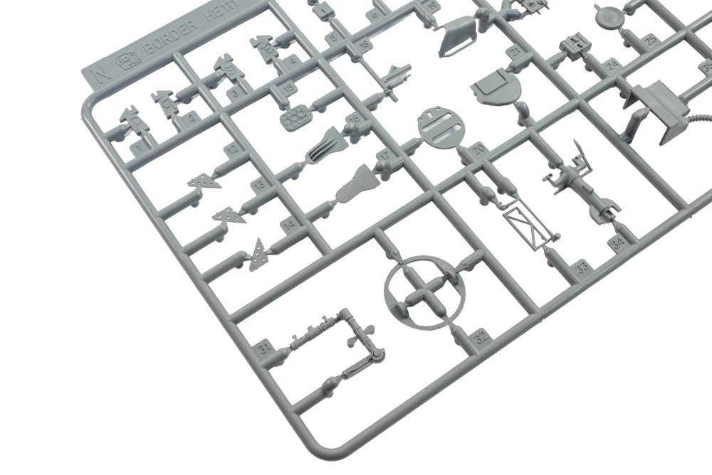
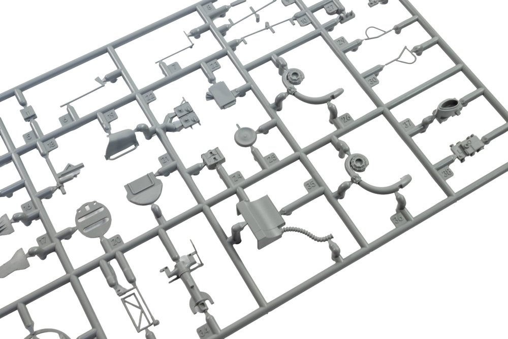
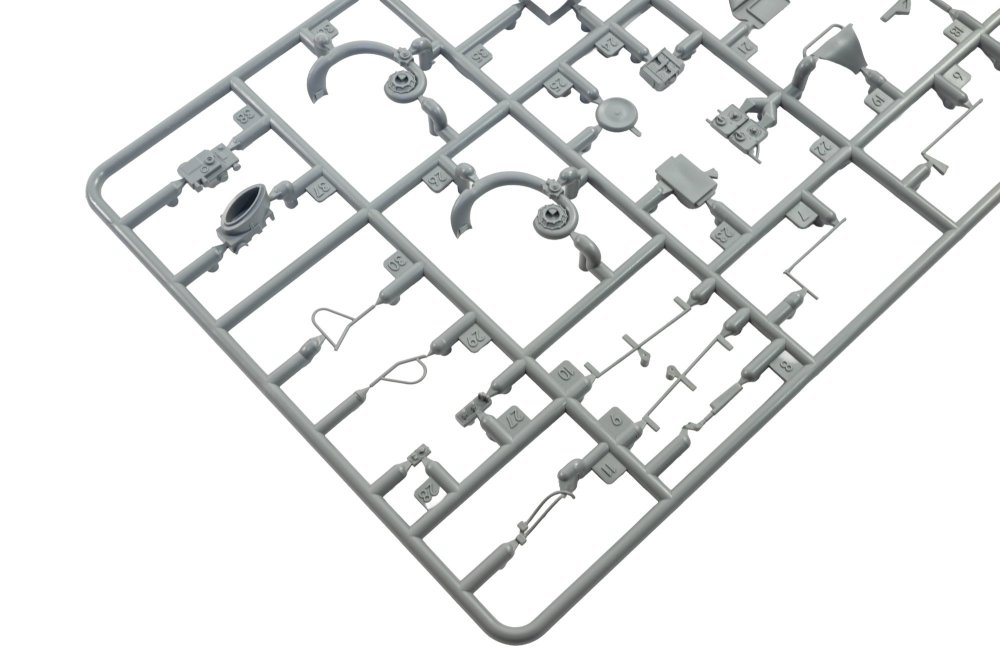
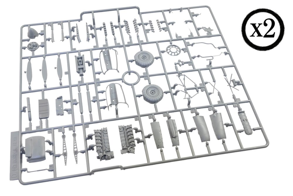
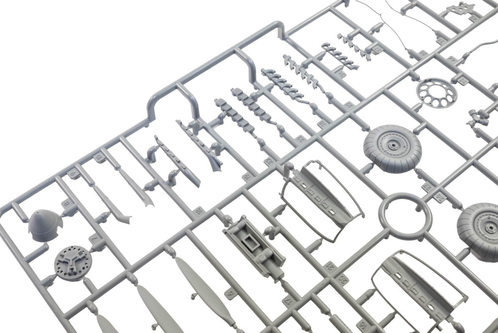
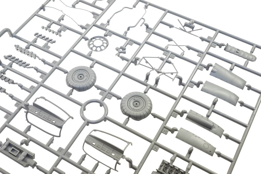
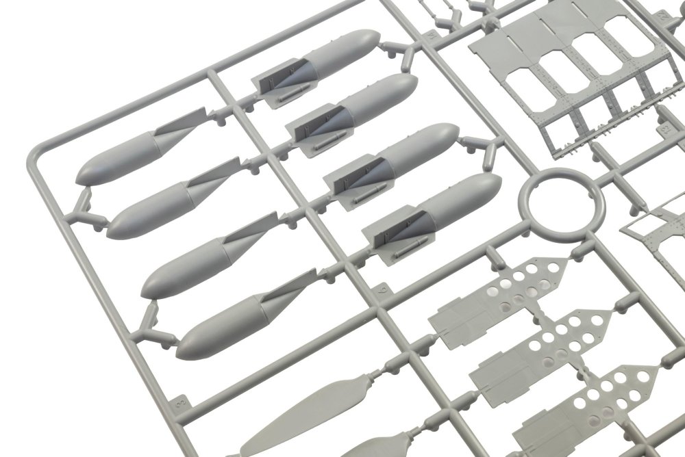
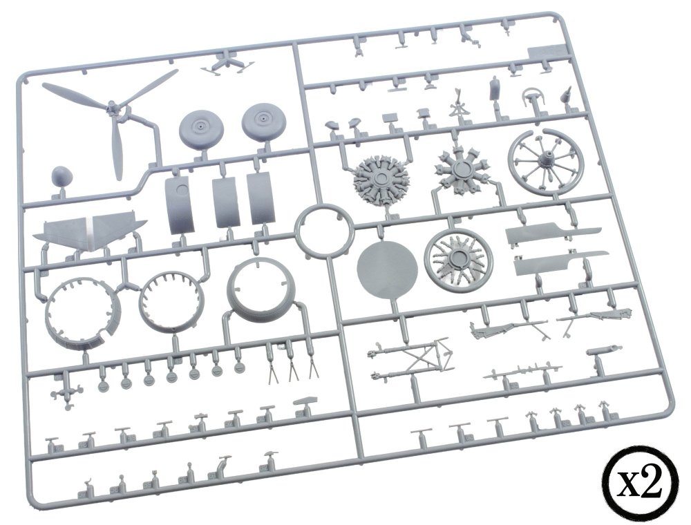
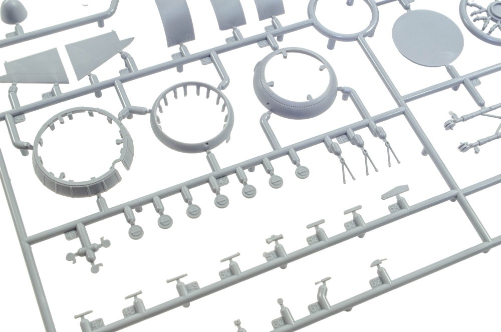
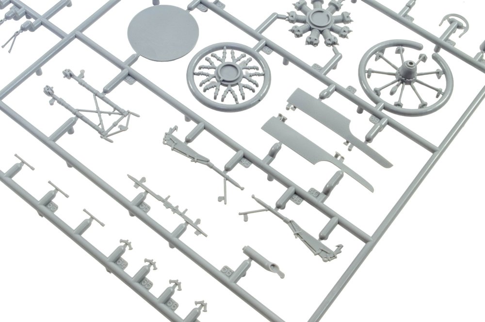
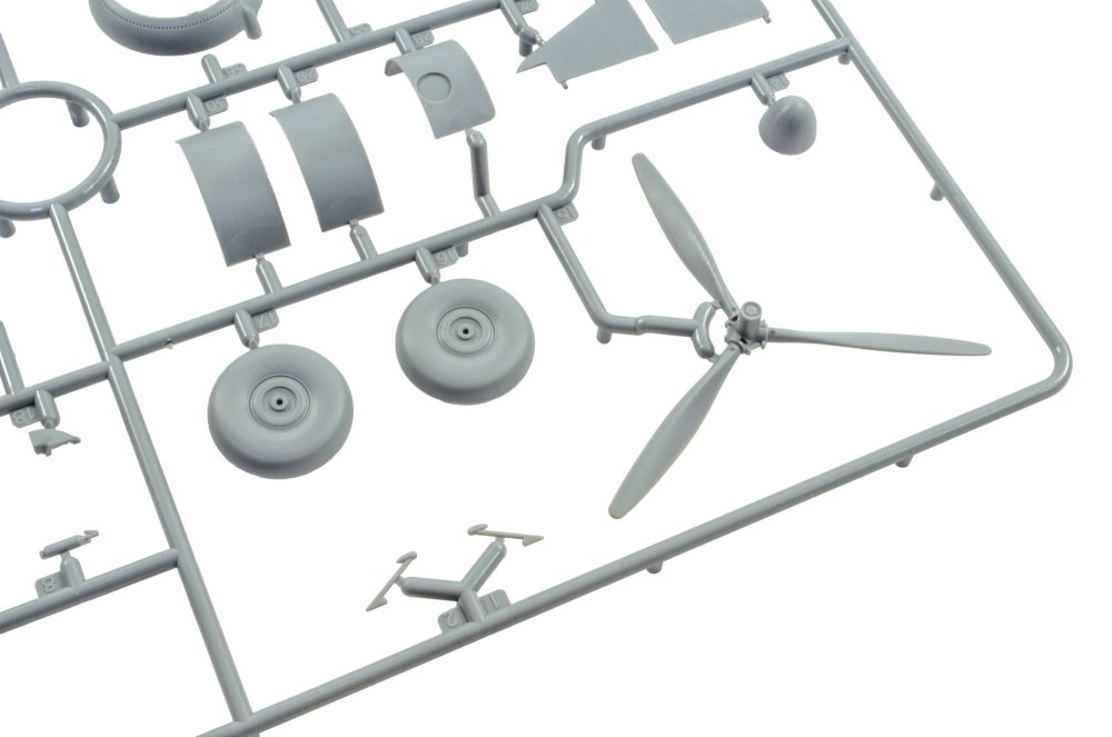
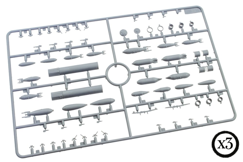
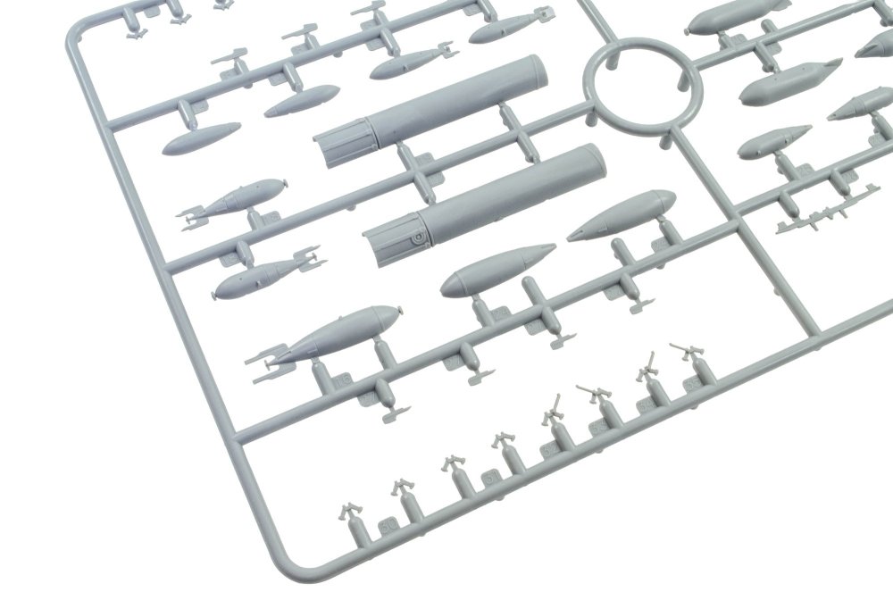
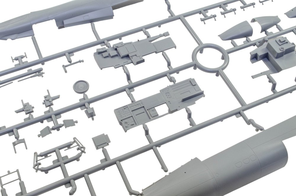
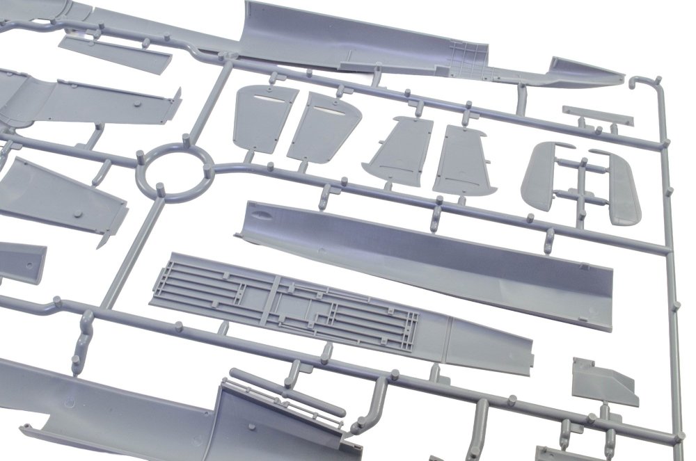
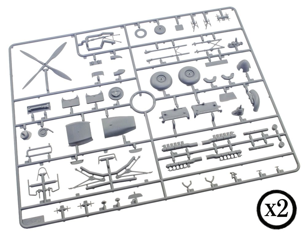
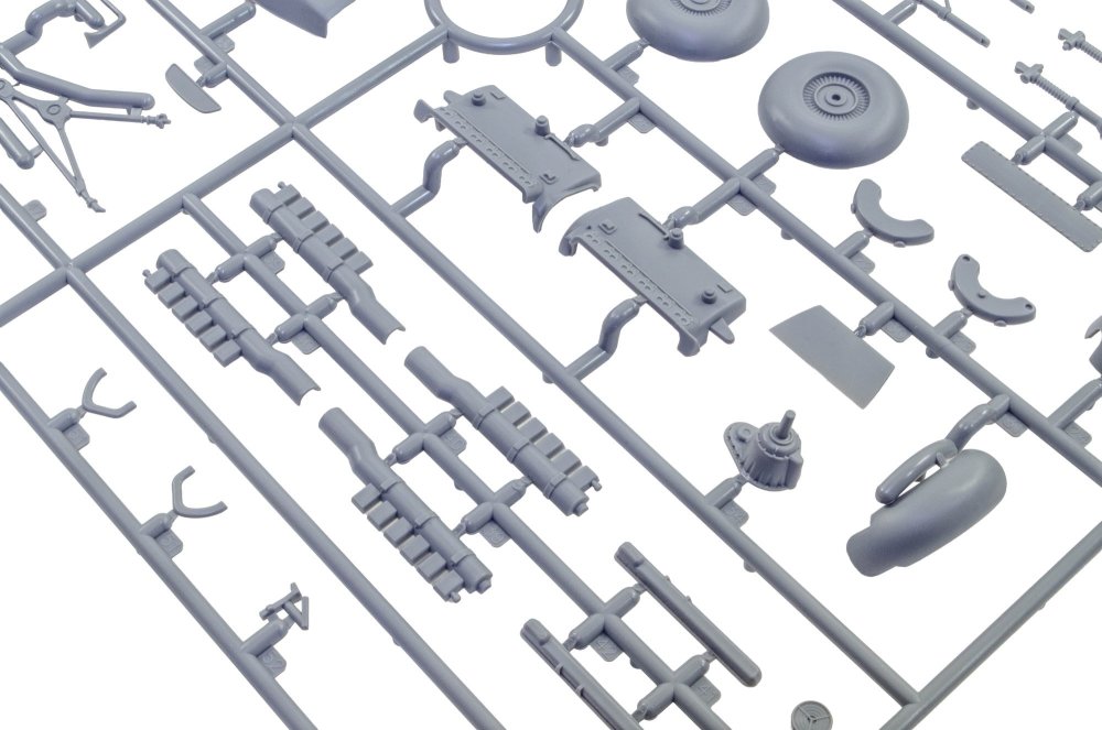
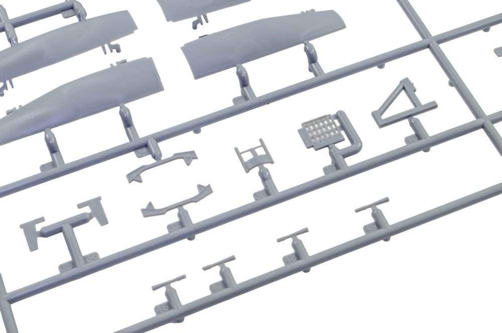
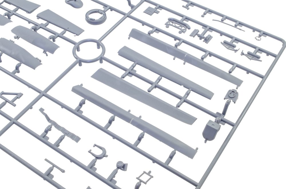
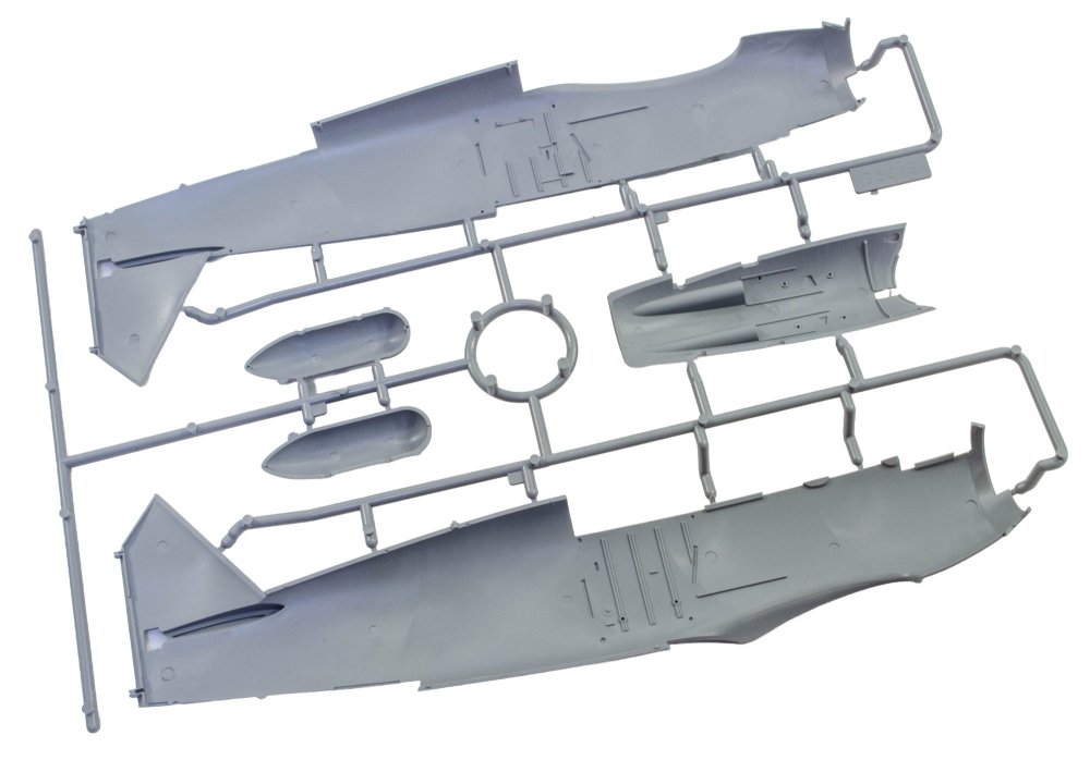
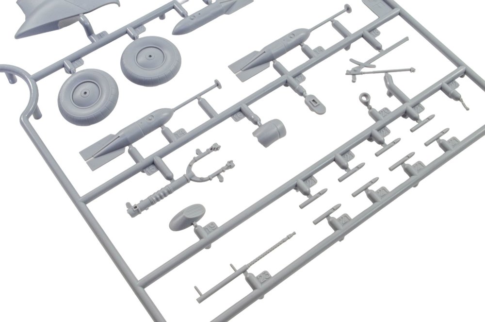
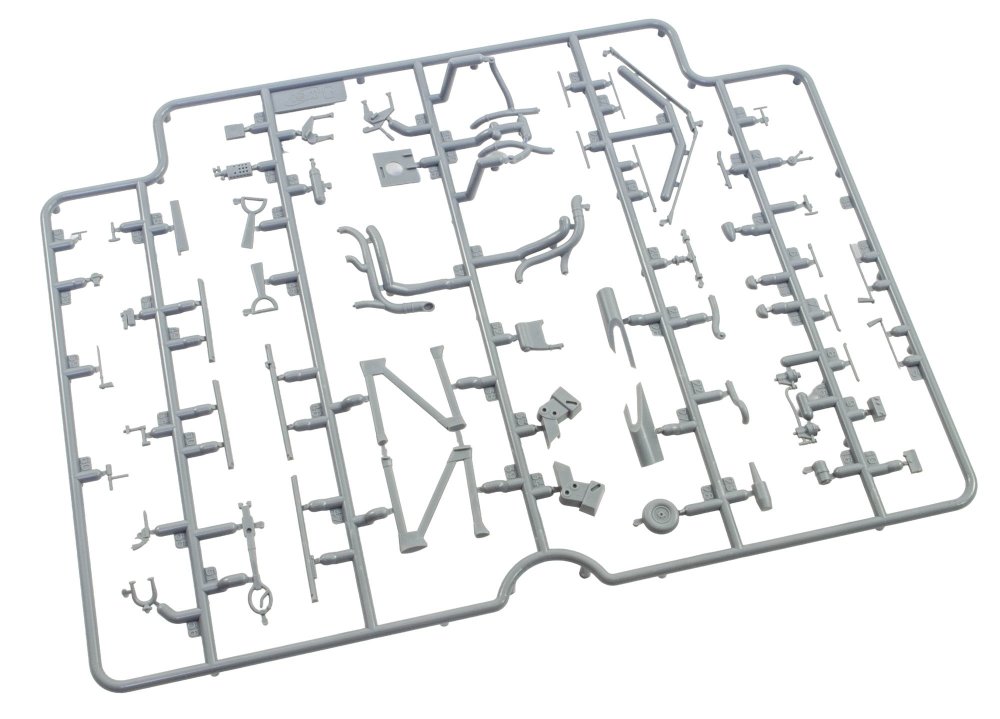
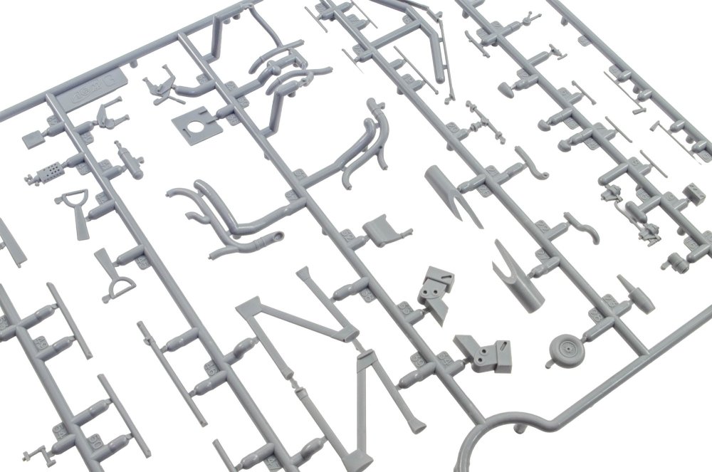
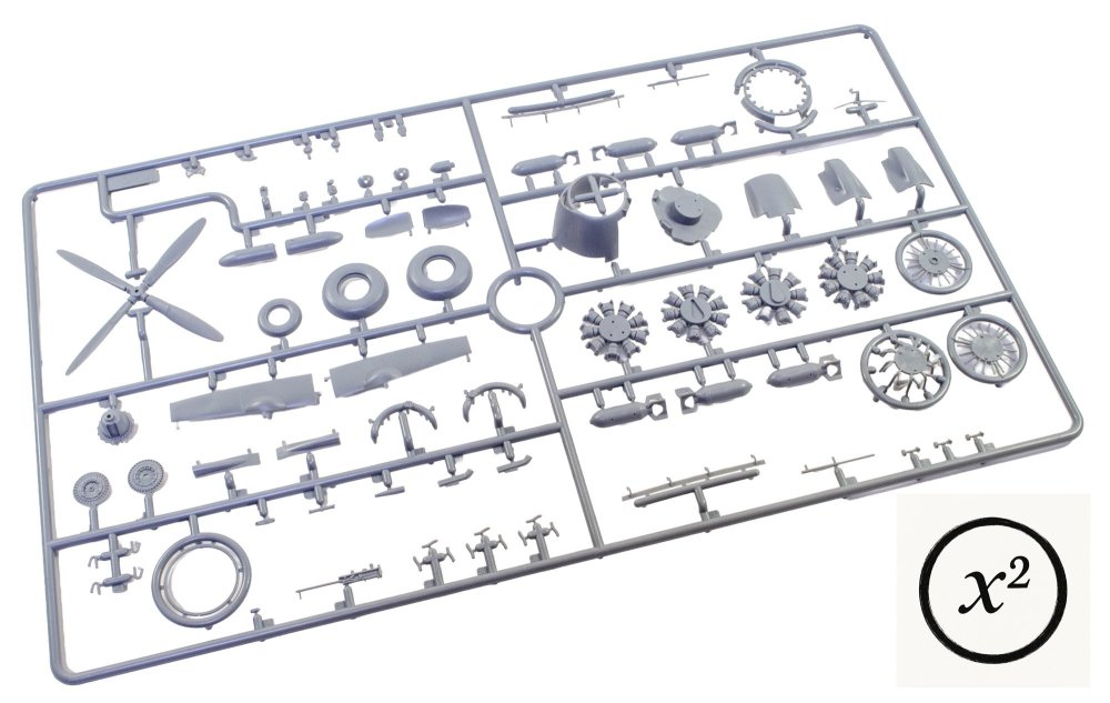
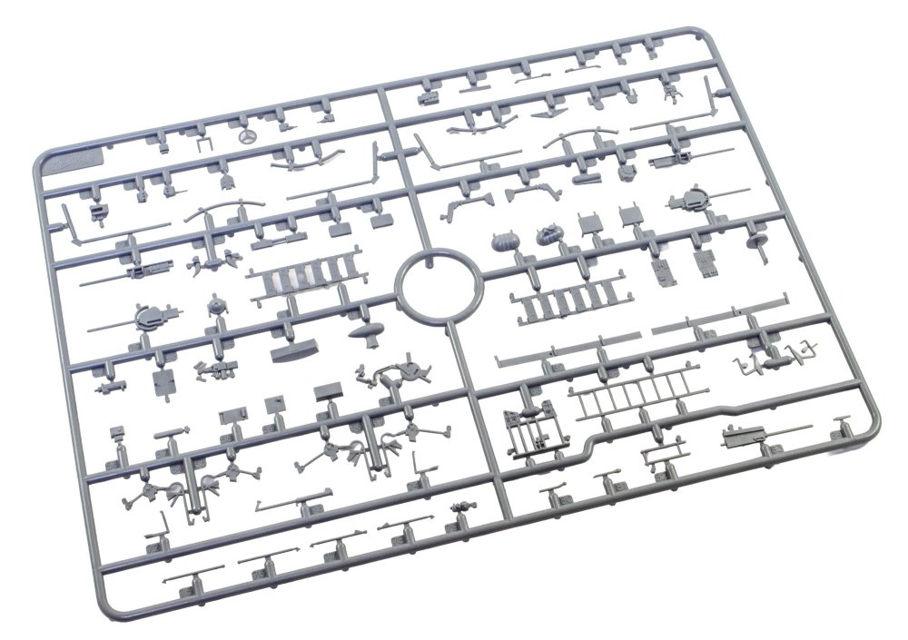
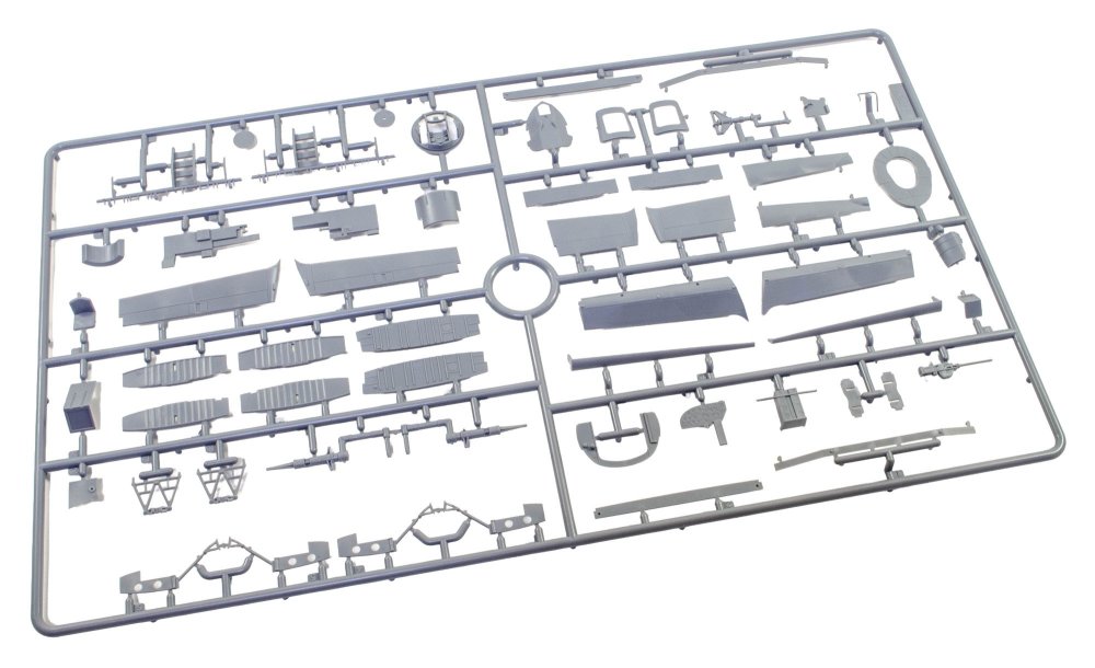
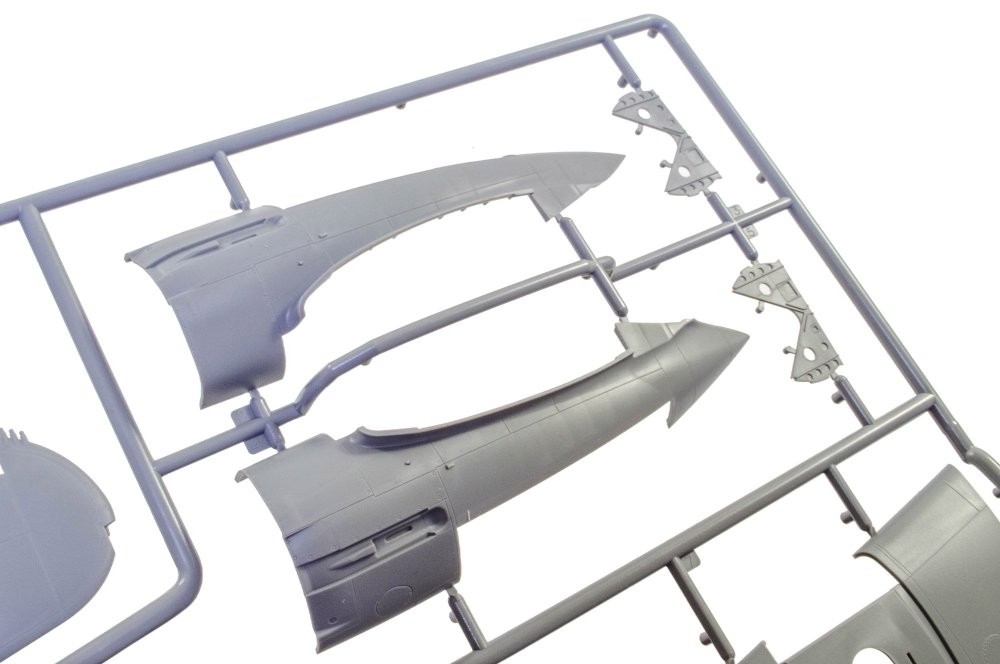
SPRUE M If you ignore the belly bomb section and gondola position, Border have split the lower fuse into two further sections; one immediately aft of the gondola and the last part extending to the tail wheel. There's some serious oil canning distress in this area too. Maybe that's likely indicative of the stresses of multiple landings...I really have no idea. Also seen here are the ailerons and multiple cockpit parts. SPRUE N Yet another sprue not on the parts map. This is located in a box, along with Sprue S. Here, you will generally see smaller parts for both the cockpit and Jumo engines. SPRUE O The added graphic shows there are two of these sprues, dealing with many of the Heinkel's doubled up parts, such as engine frames, wheels, prop blades and parts, engine intakes, cowl panels, Jumo engine, and also exhaust stubs. The wheels are weighted too, with a flat that indicates what a weighty machine this was. Again, this sprue is further protected within a cardboard box. Look at the fragility of some of these parts! SPRUE P This is another sprue for which two are included. This should need no introduction. Here are found the internal SC250 bombs, along with the bomb cages. A few non-weapon parts have snuck onto this sprue, such as the spinners and more prop blades of a different shape. The included prop blades in this kit give the modeller the choice of using the aircraft's wooden blades, or the VDM metal prop blades. I am sure that very early in construction, you will need to establish exactly which aircraft you'll be building, but I'm not very confident that for some details that these are clearly indicated. Might be useful to do a Google image trawl. MORE SOON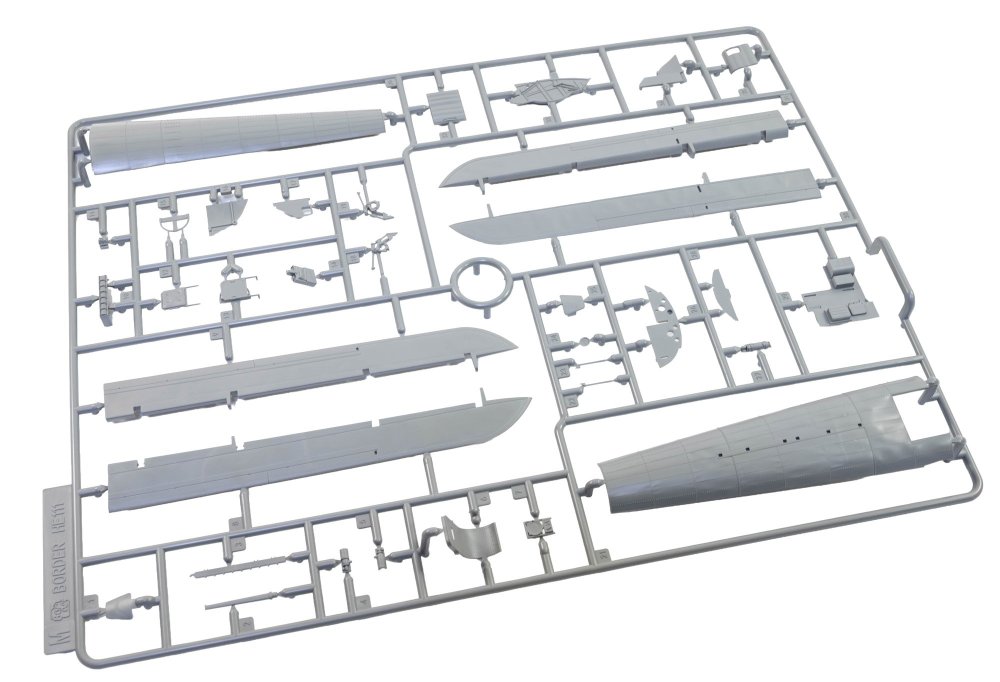


-
border model Border Model 1:35 Heinkel He 111H-6
JayDee replied to JayDee's topic in Aircraft Reviews
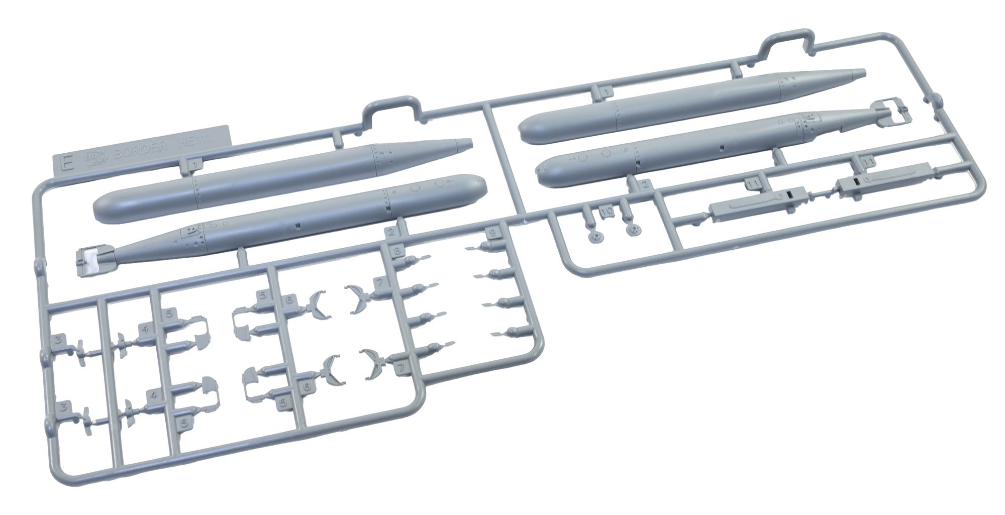
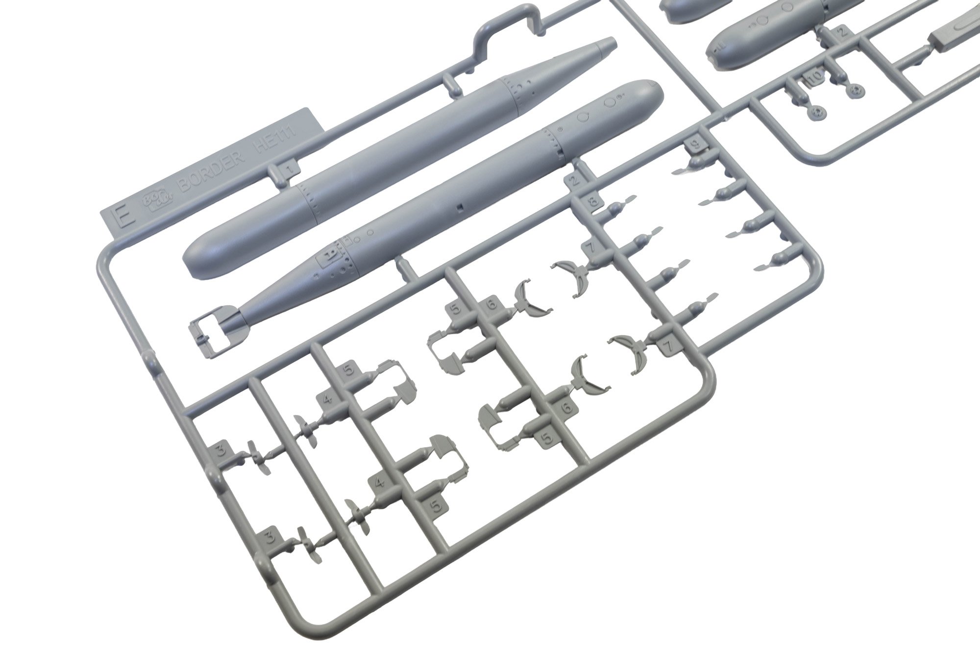
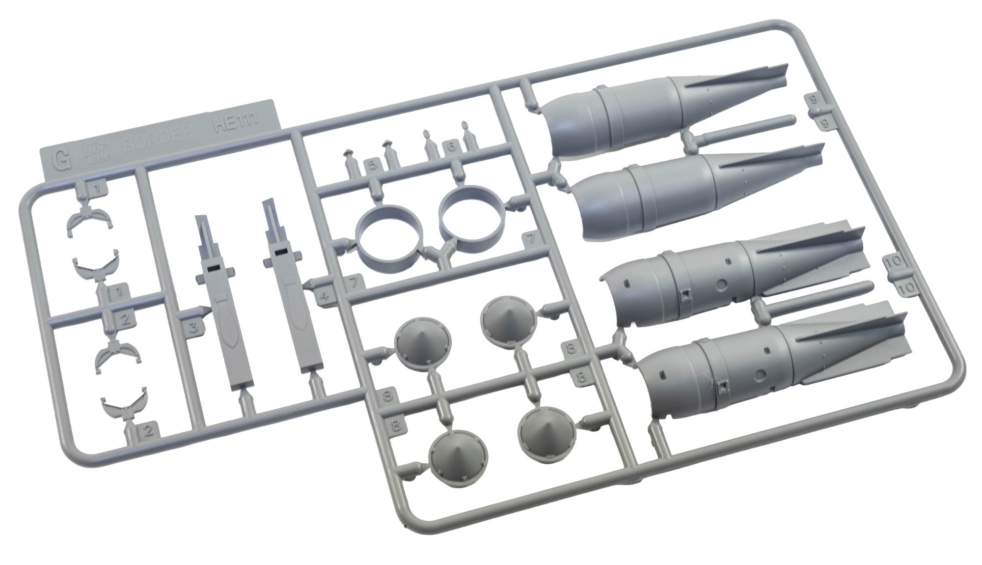
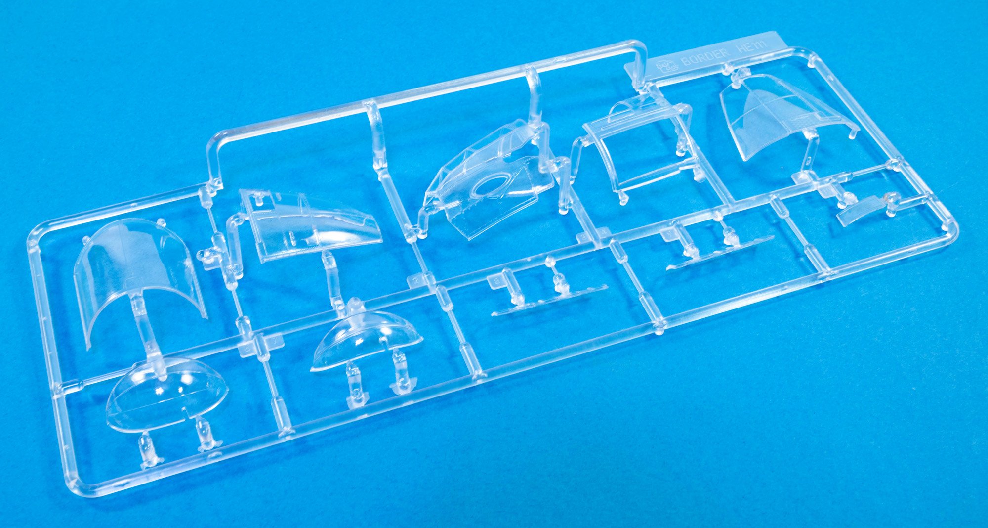
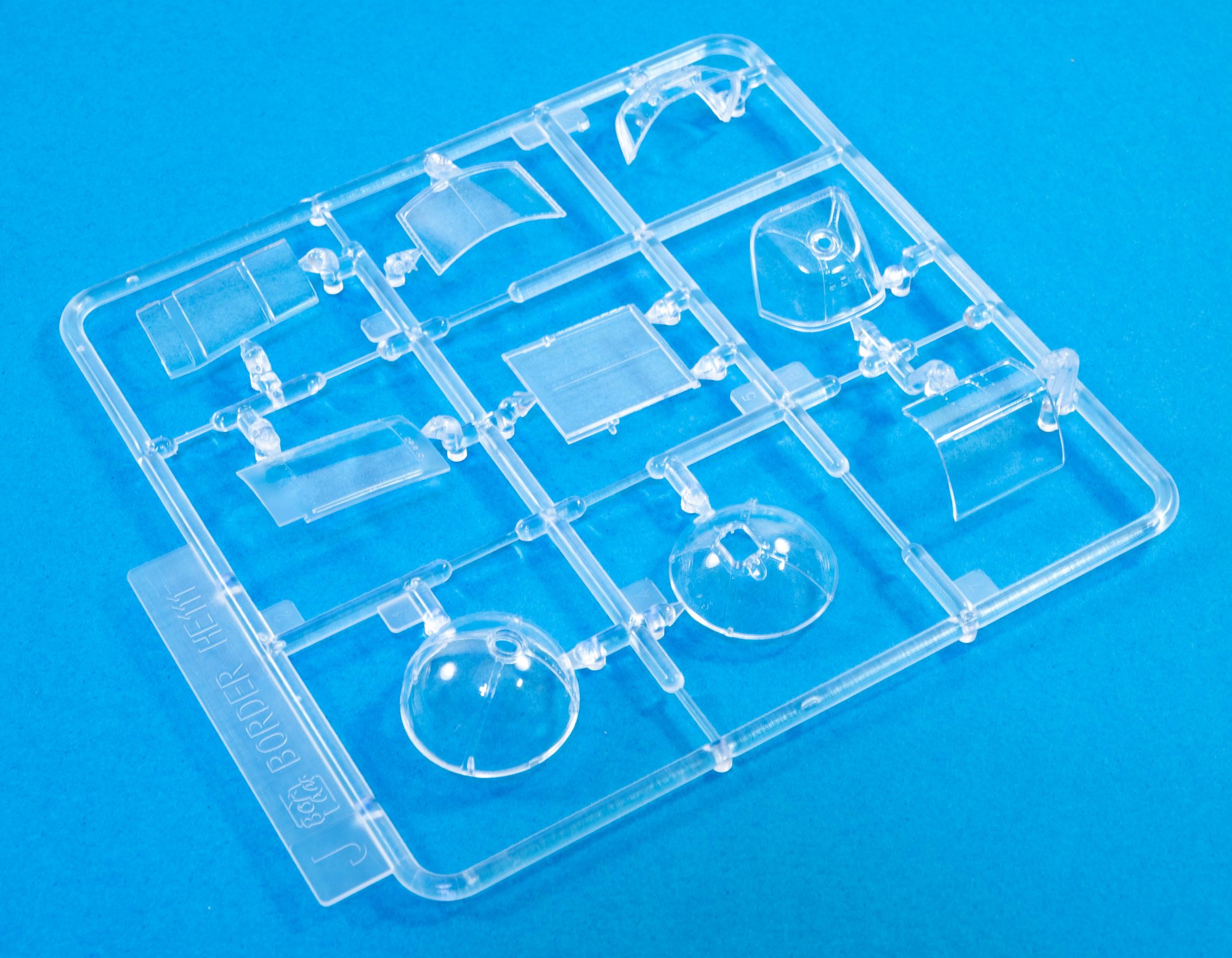
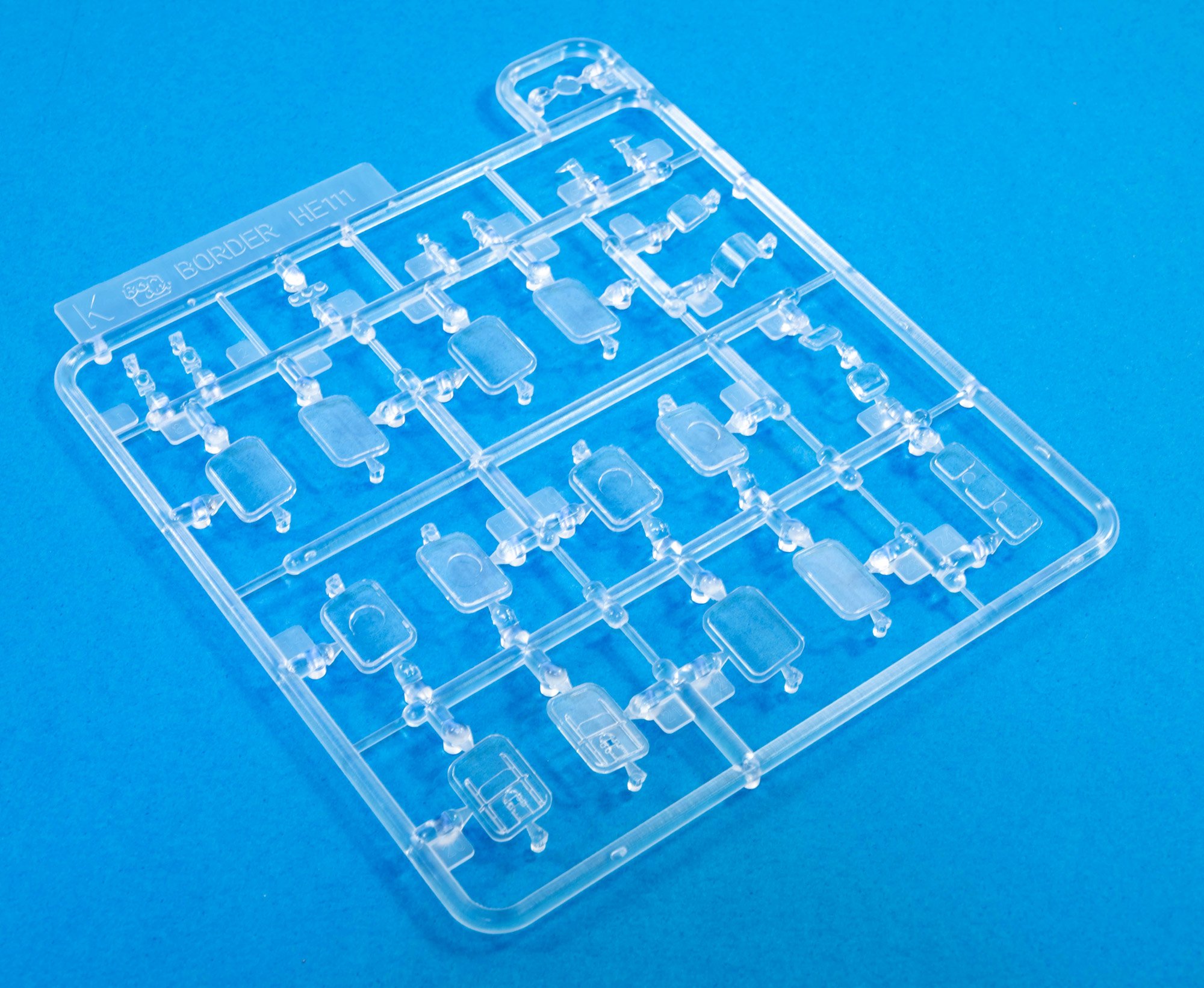
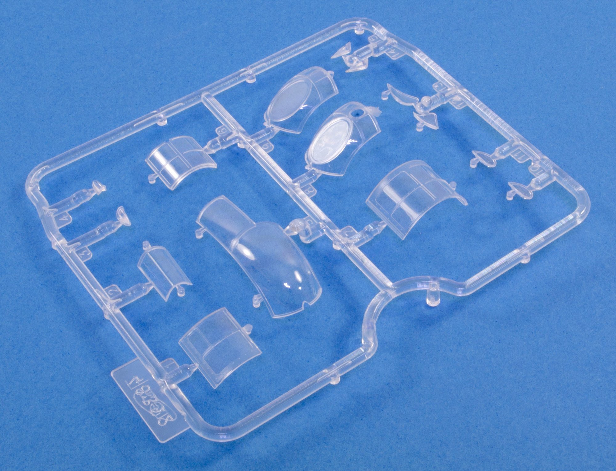
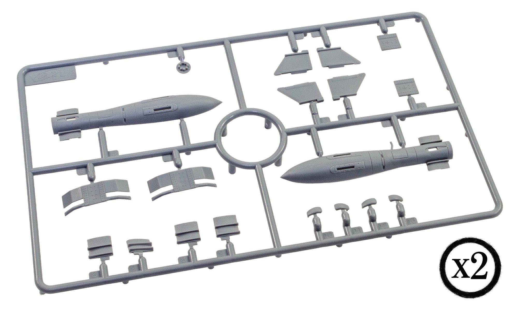
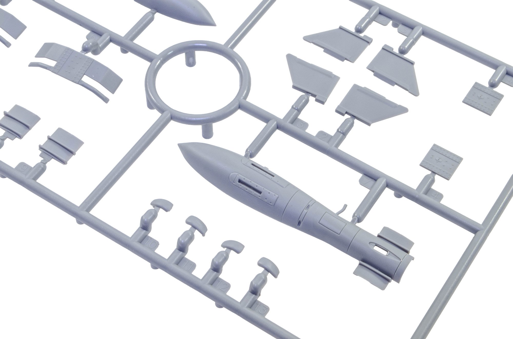
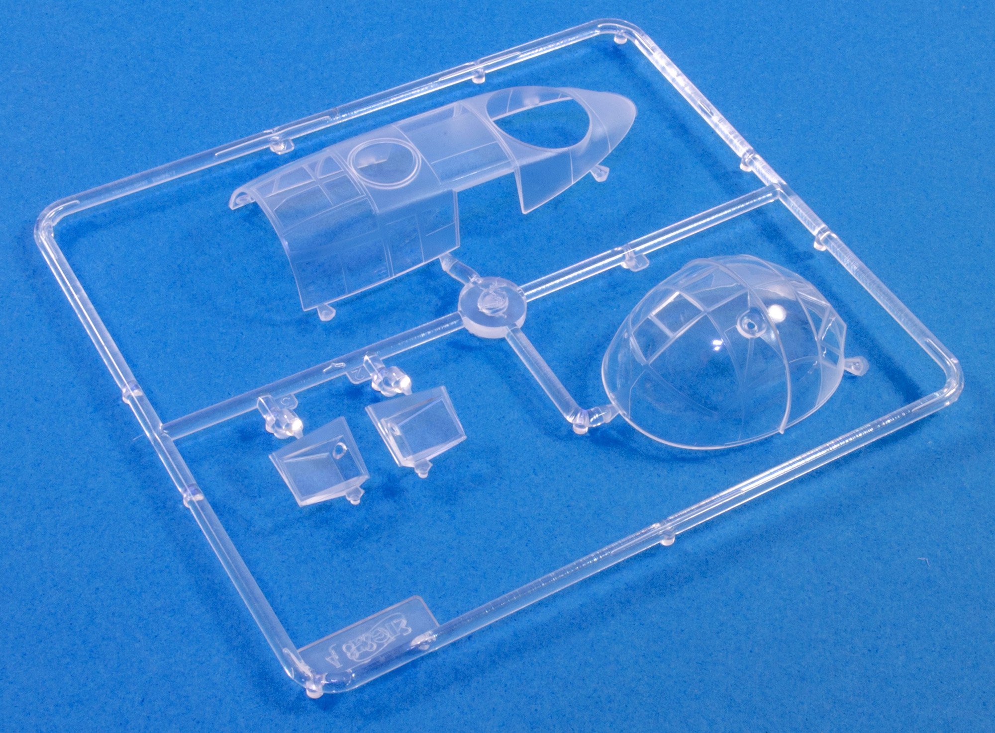
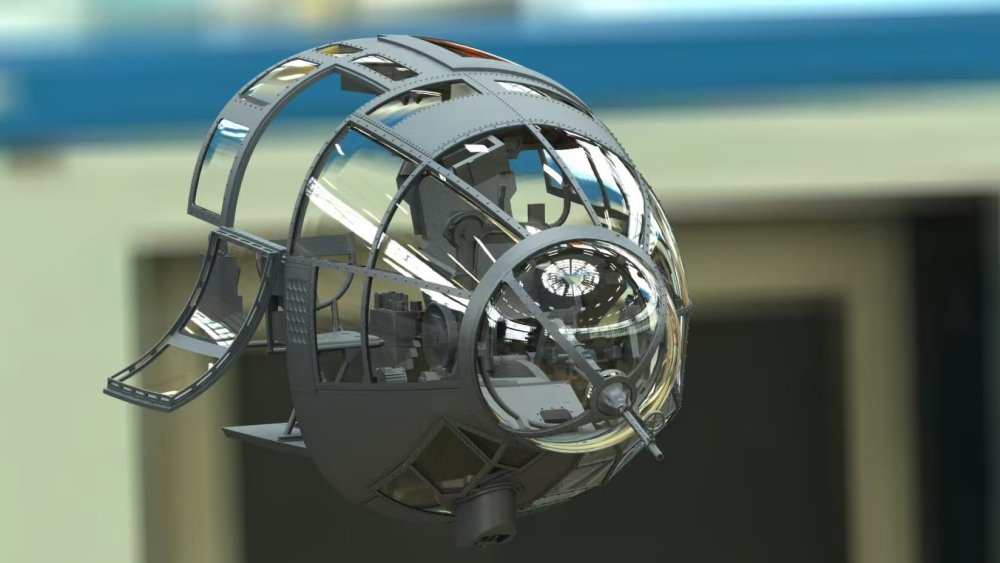
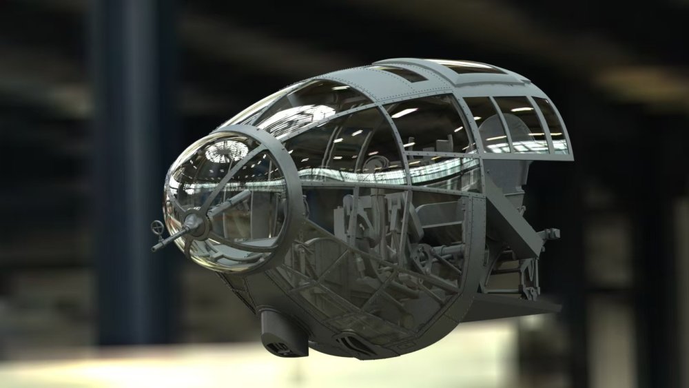
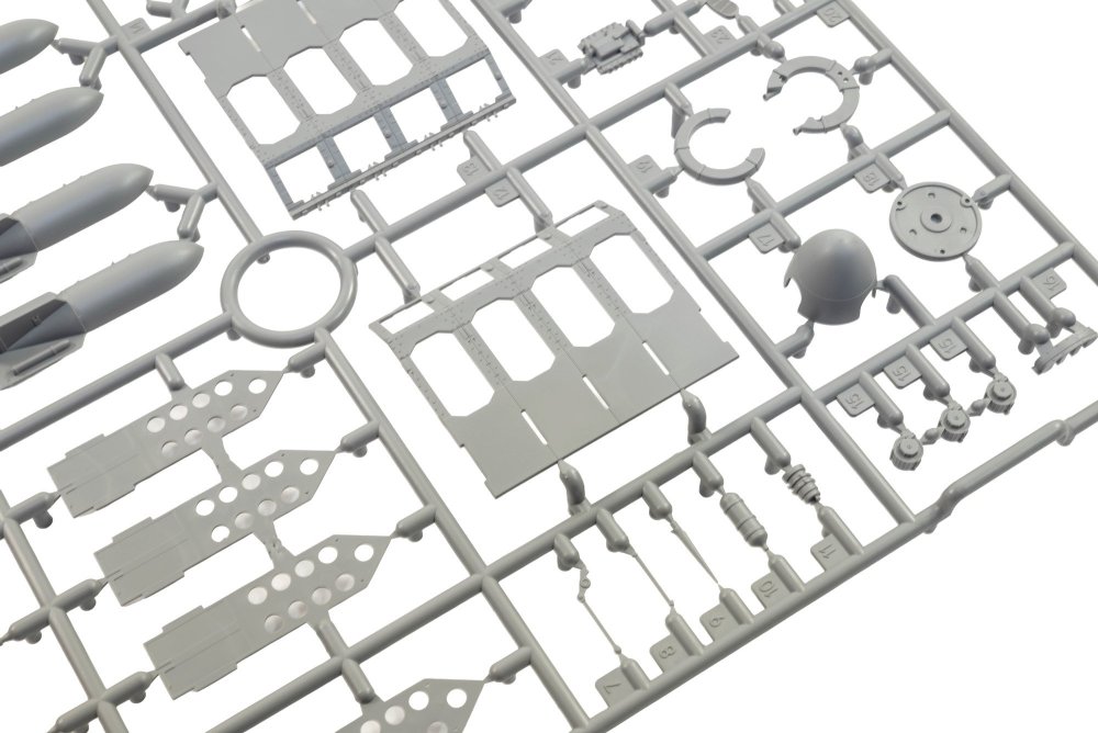
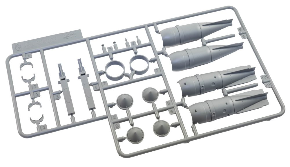
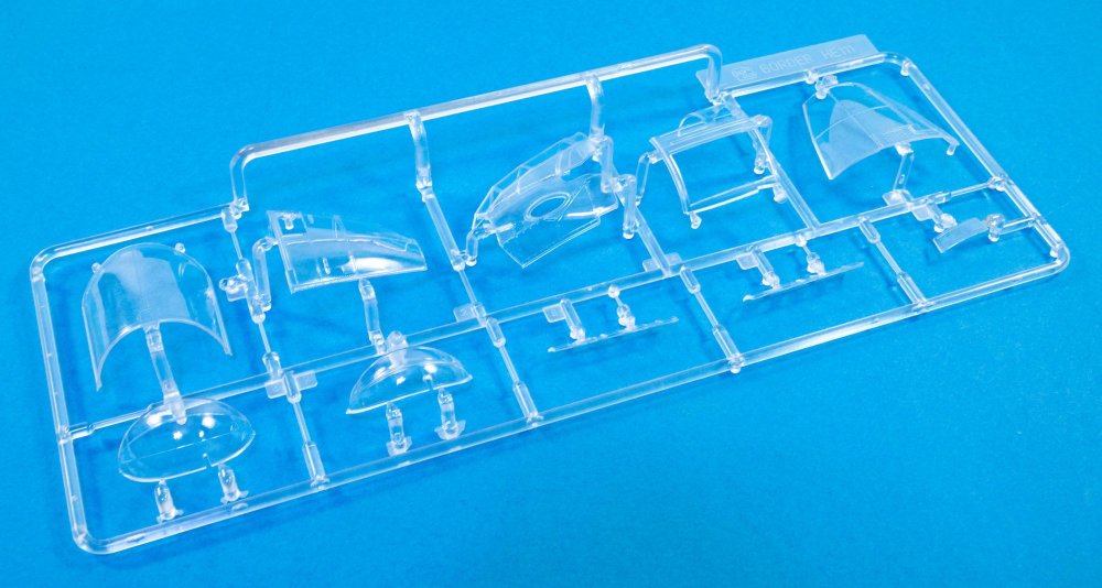
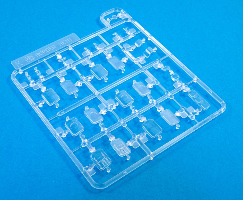
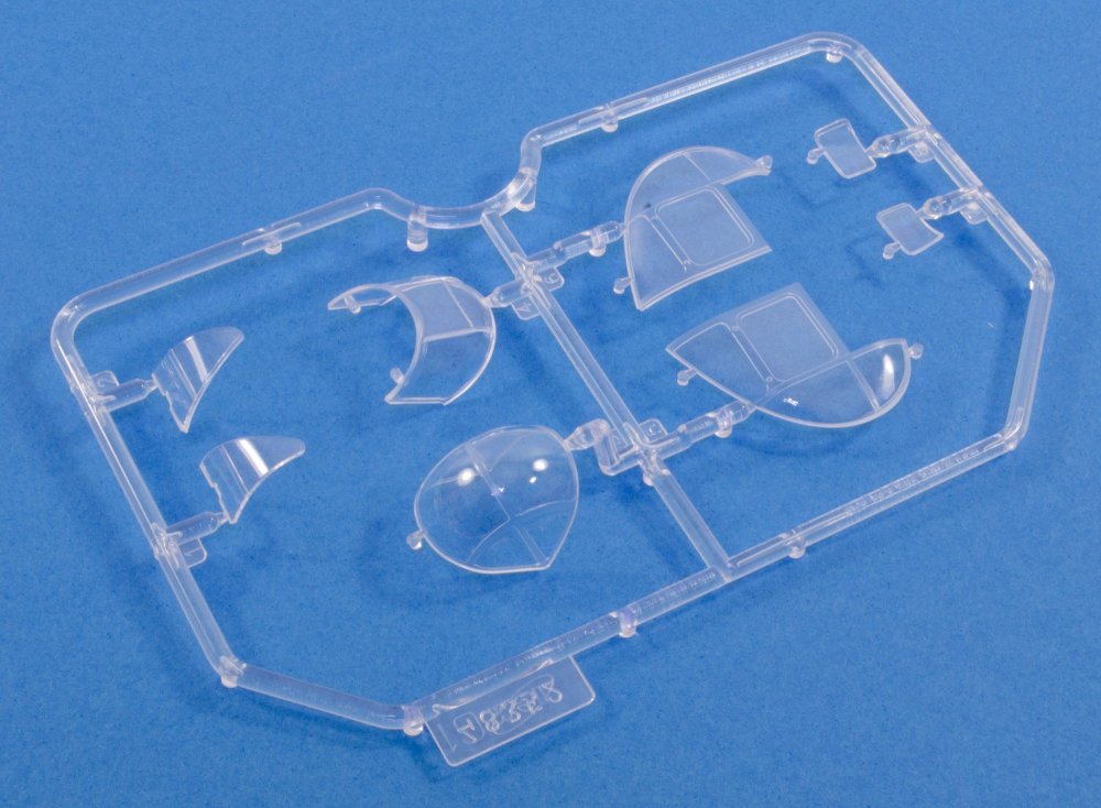
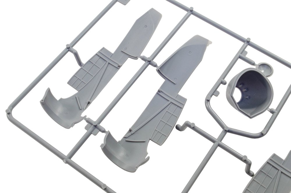
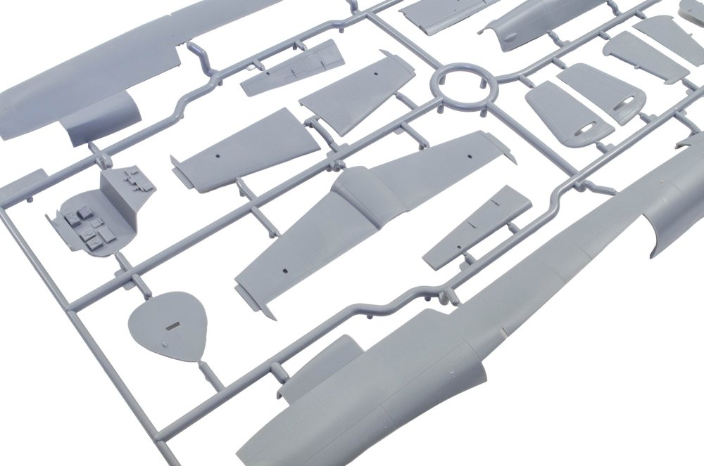
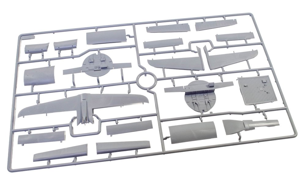
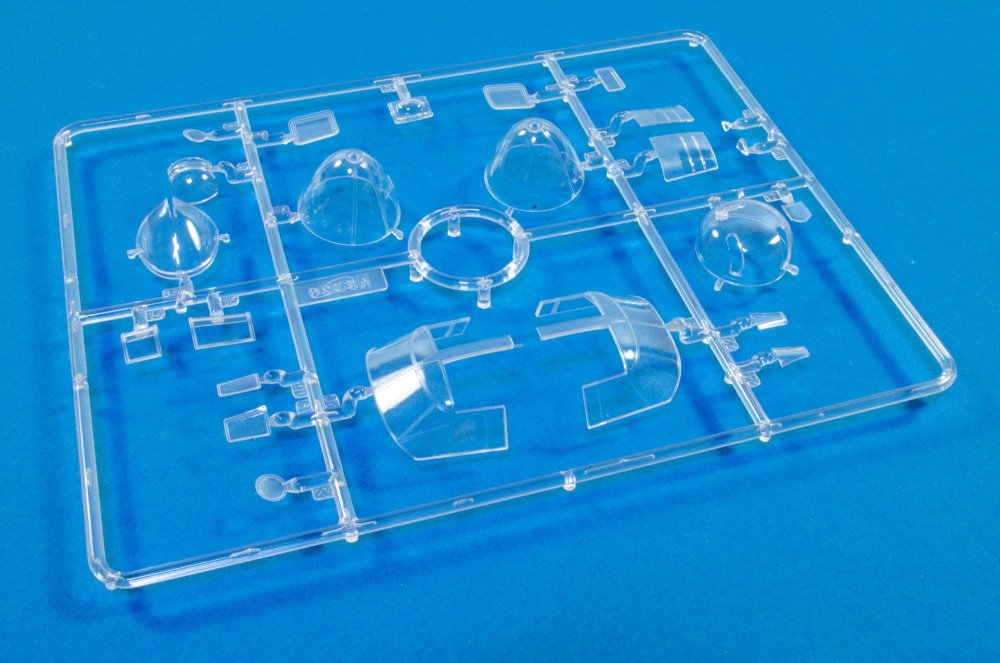
PART TWO SPRUE E All parts here are to build the two F5b torpedoes. Photo-etch parts are also included to supplement the plastic details. The weapons mounting points for inside the belly mount, are seen here under the halves on the right hand side. SPRUE F There are two belly options in this kit, with this one having the fixed mounts for the SC1000 bombs/F5b torpedoes incorporated into it. The detail is excellent and everything looks amazing crisp and refined. The rectangular part on this sprue is the mounting plate for the internal bomb cages. SPRUE G This is one of the sprues that IS shown on the parts map, but not labelled along with E & F. These parts are for the SC1000 bombs, along with their mounting racks. SPRUE H Quite a few obvious parts here, such as the fuselage mid upper section with the gun position, waist gunner platform, bomb bay fore and aft bomb bay sections, and the stabiliser halves. The latter parts, along with the vertical stabiliser, are the only real fixed structural elements that will need a swipe of a sanding stick to remove seams. SPRUE I This isn't shown at all on the parts map. Here you see the alternative bomb bay belly section, with cutout sections for the bomb drops. Different door sets are provided for both open and closed positions. The vertical stabiliser is supplied here, along with the two-part rudder. Two different tail cone options are also included; one with a remotely controlled MG17. Also seen here are the main gear strut units, internal fuselage bulkhead, interior waist equipment, etc. SPRUES J, K, L All of these clear sprues are supplied in separate sleeves, and then within a protective cardboard box. It's difficult to convey here, but these parts are crystal clear and are superbly moulded with definitive frame lines etc. Where parts of these sections are not glazed, the plastic is textured to represent the rest of the superstructure. As you can see, the He 111 isn't shy when it comes to glass! MORE SOON...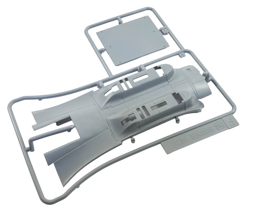


-
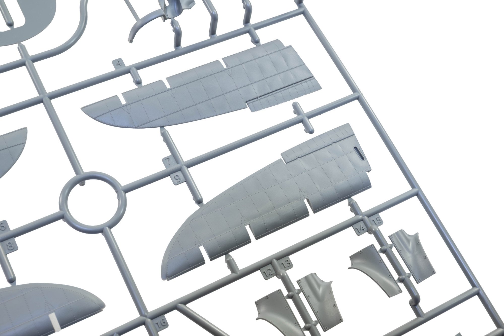
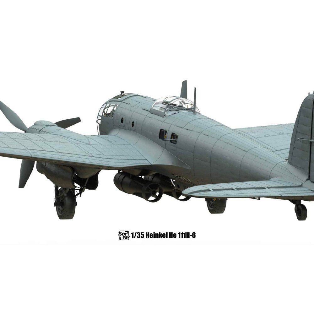
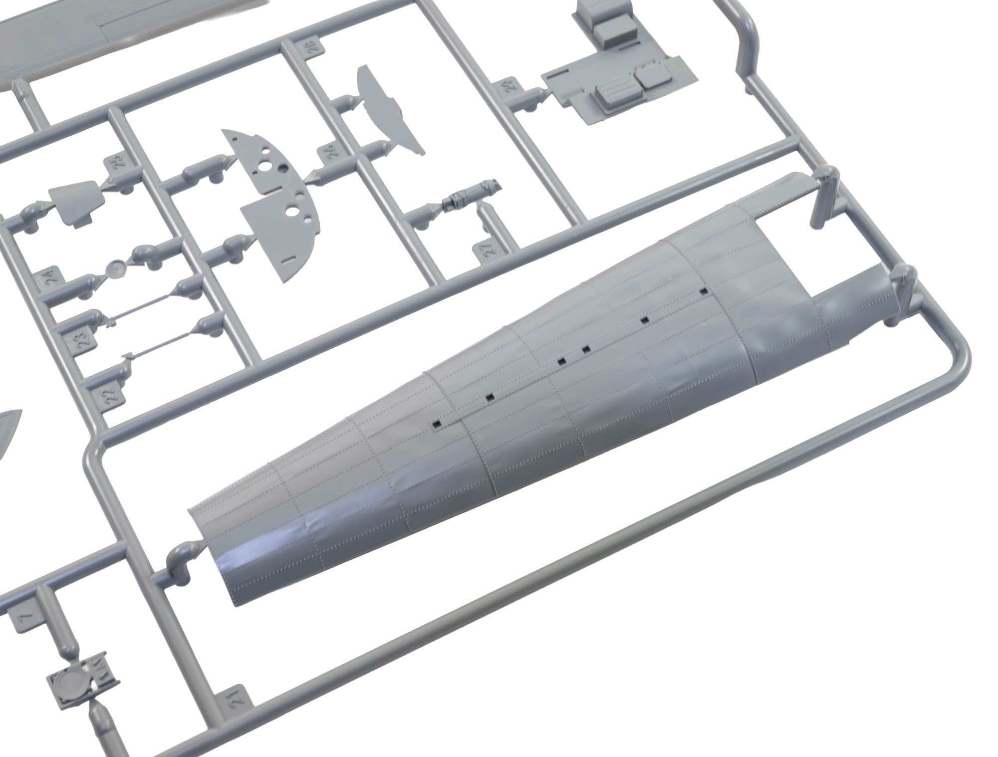
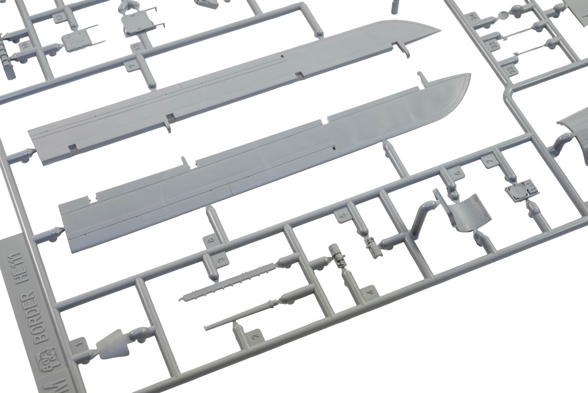
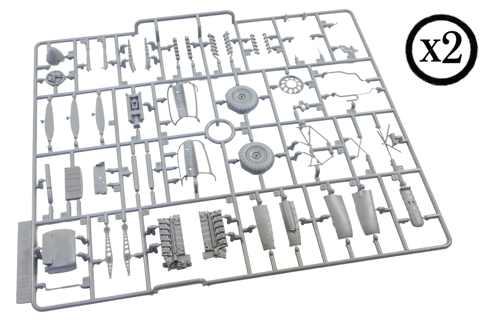
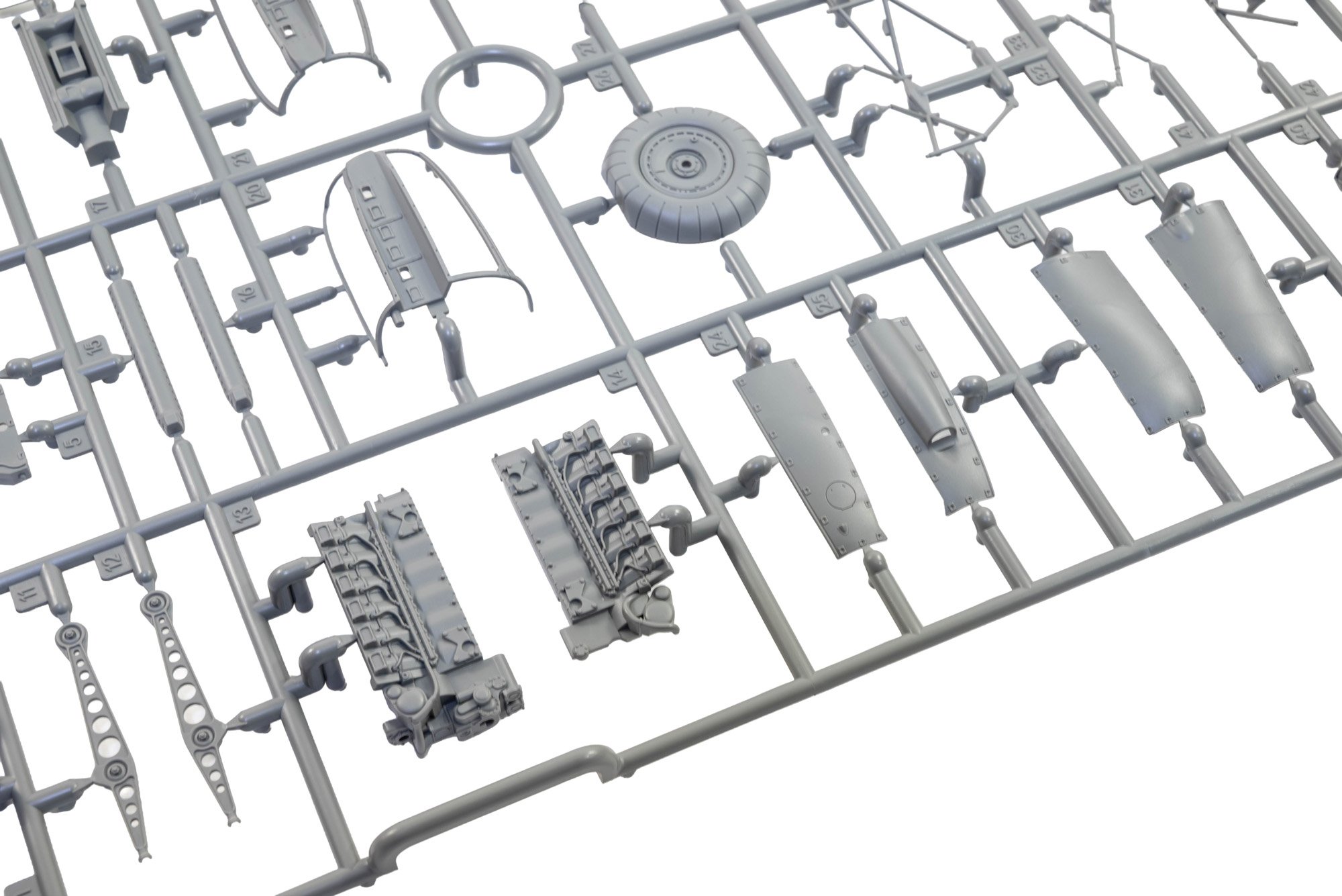
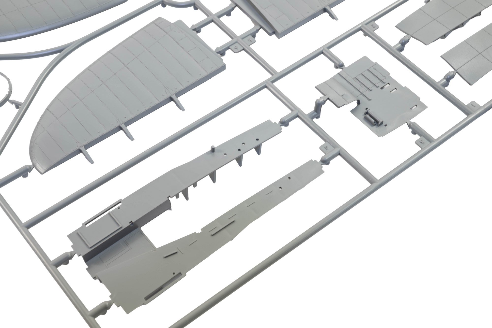
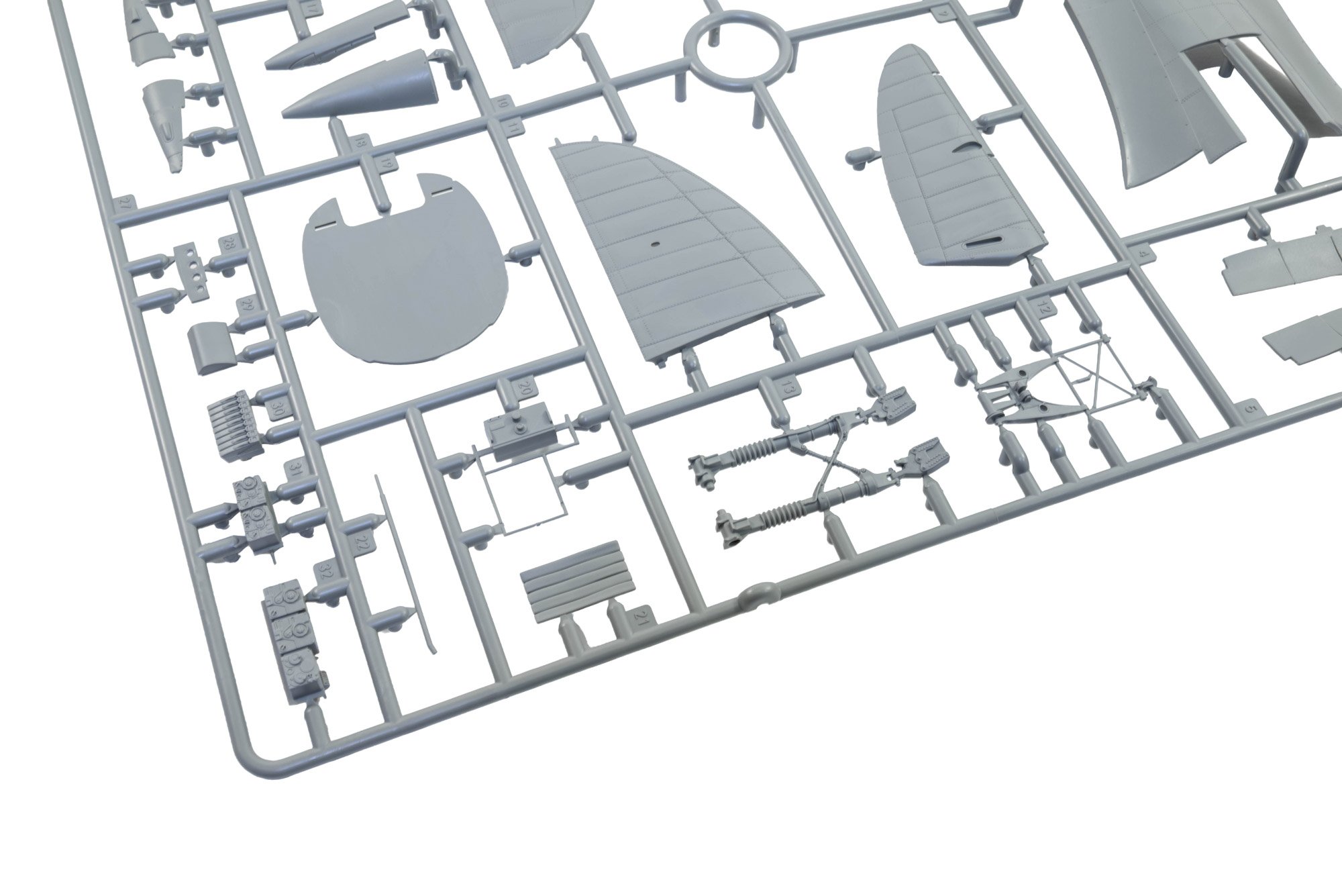
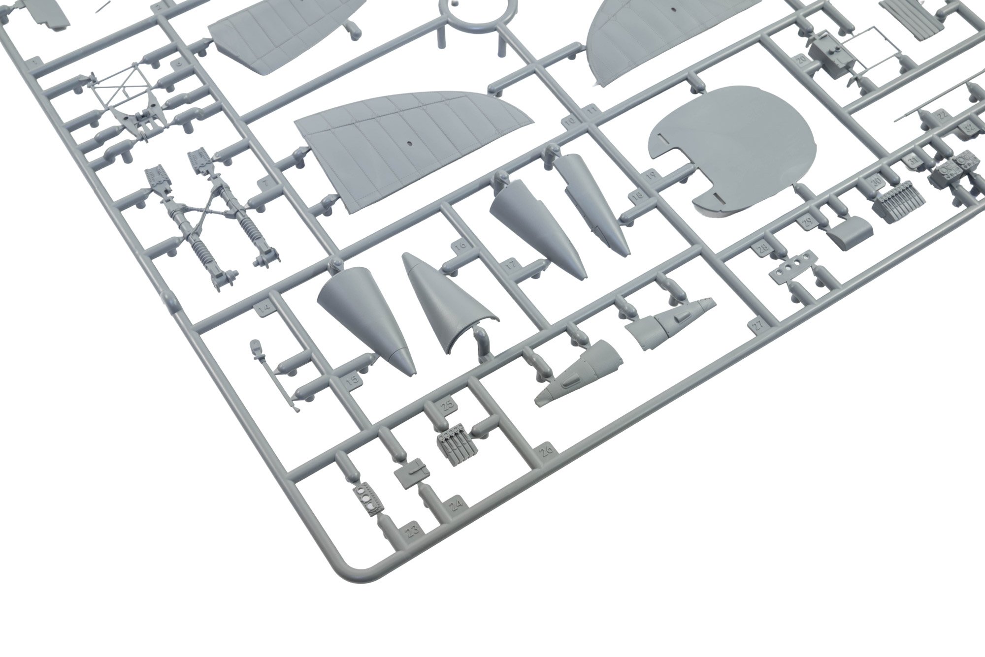
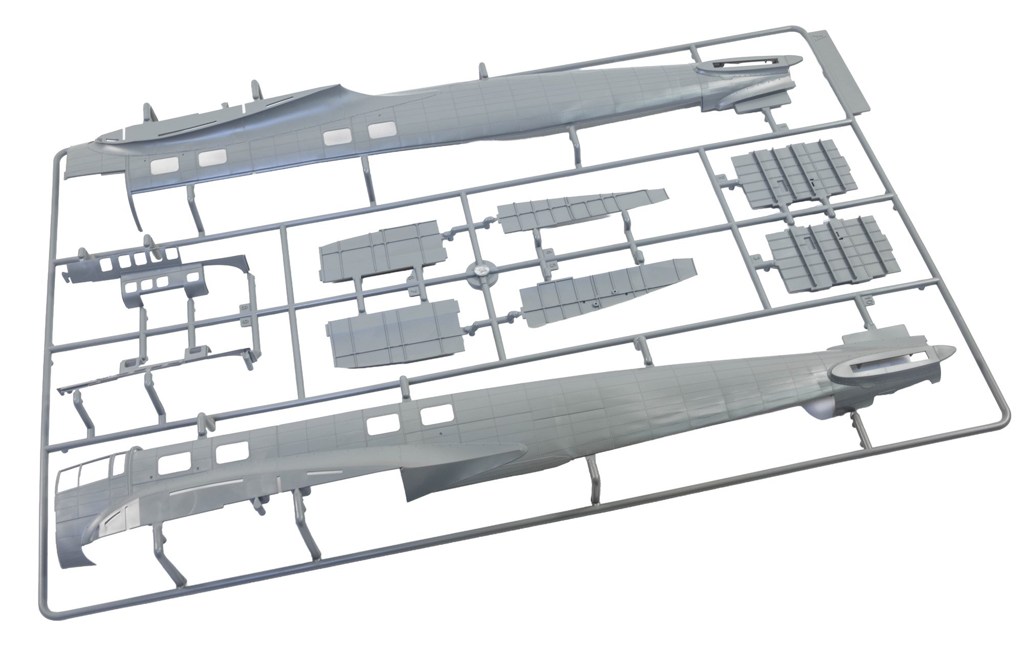
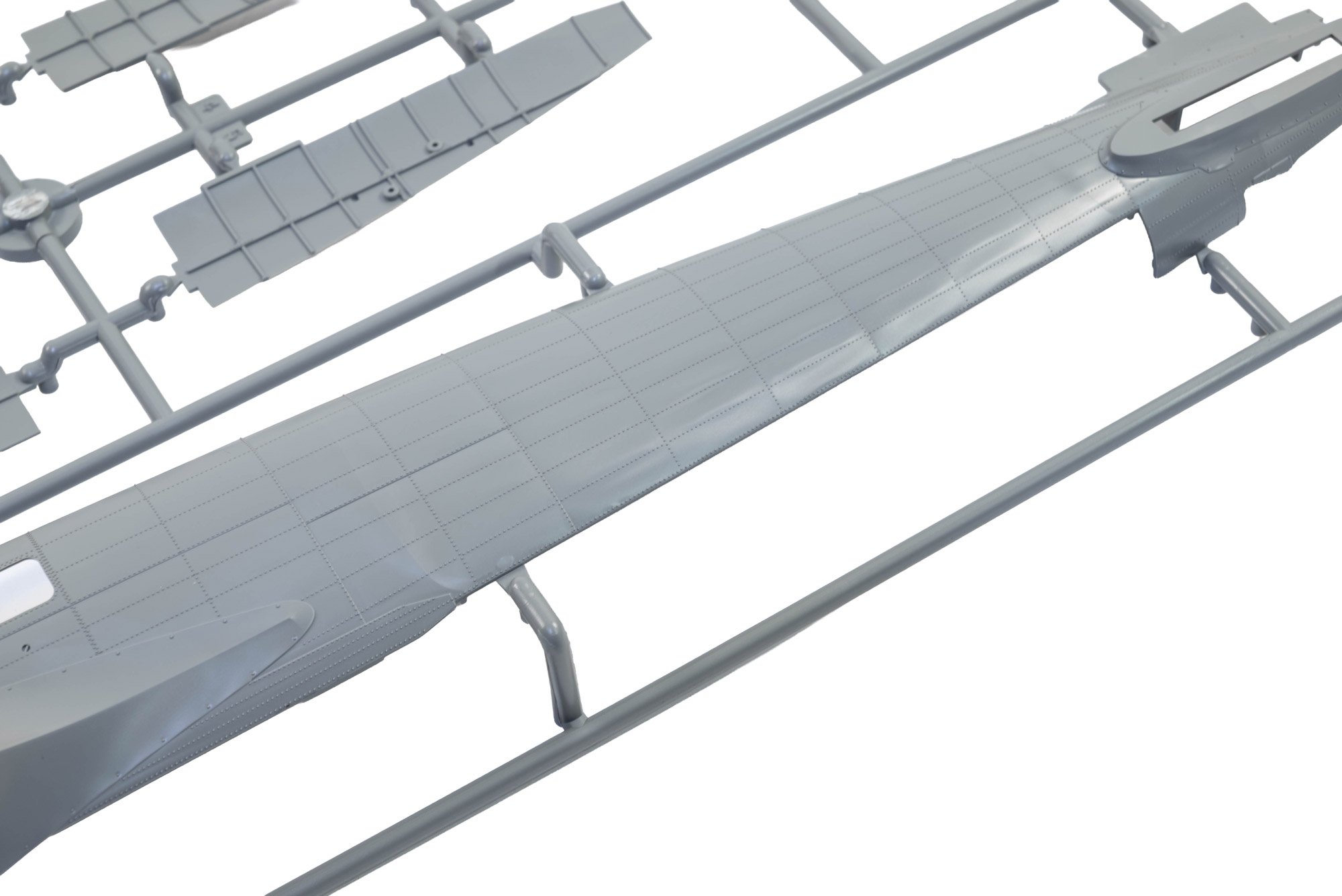
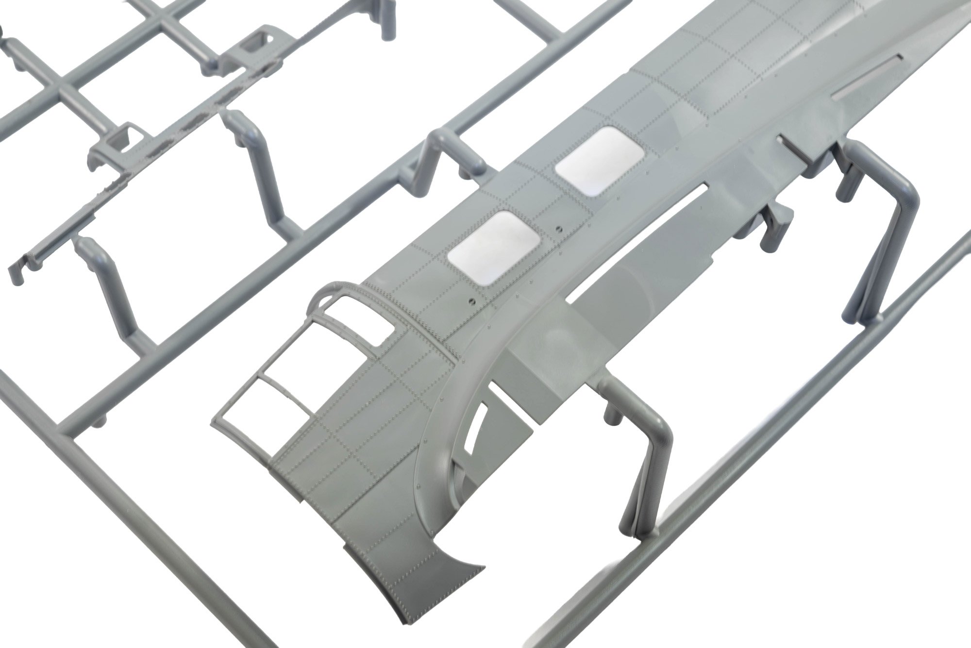
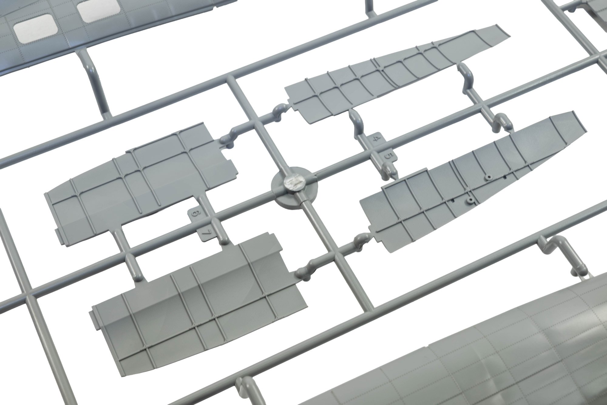
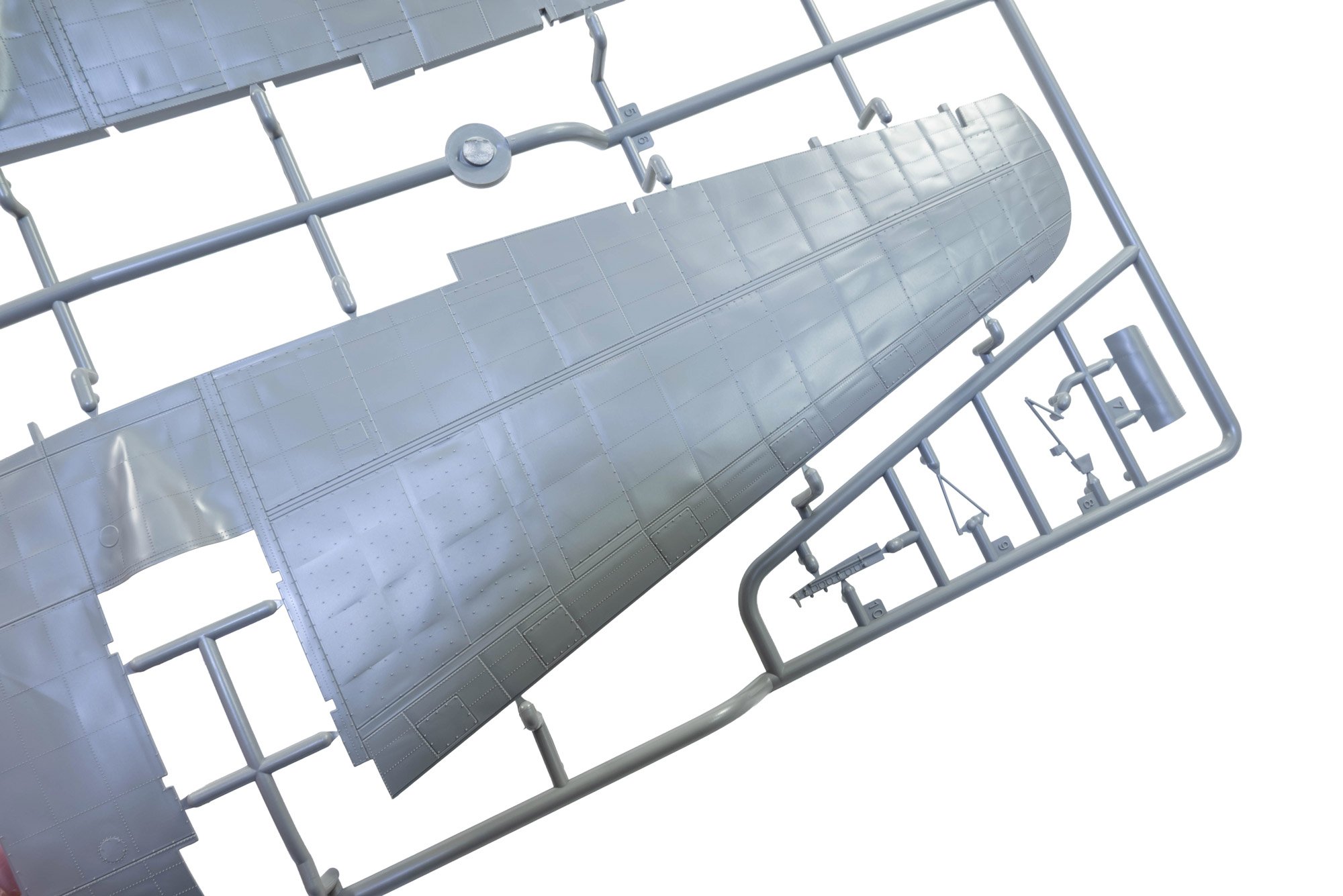
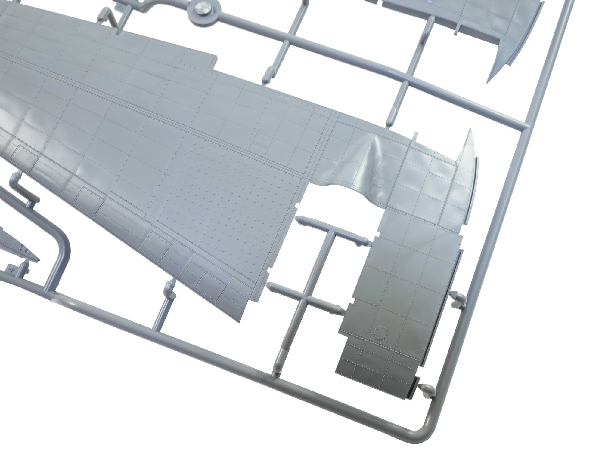
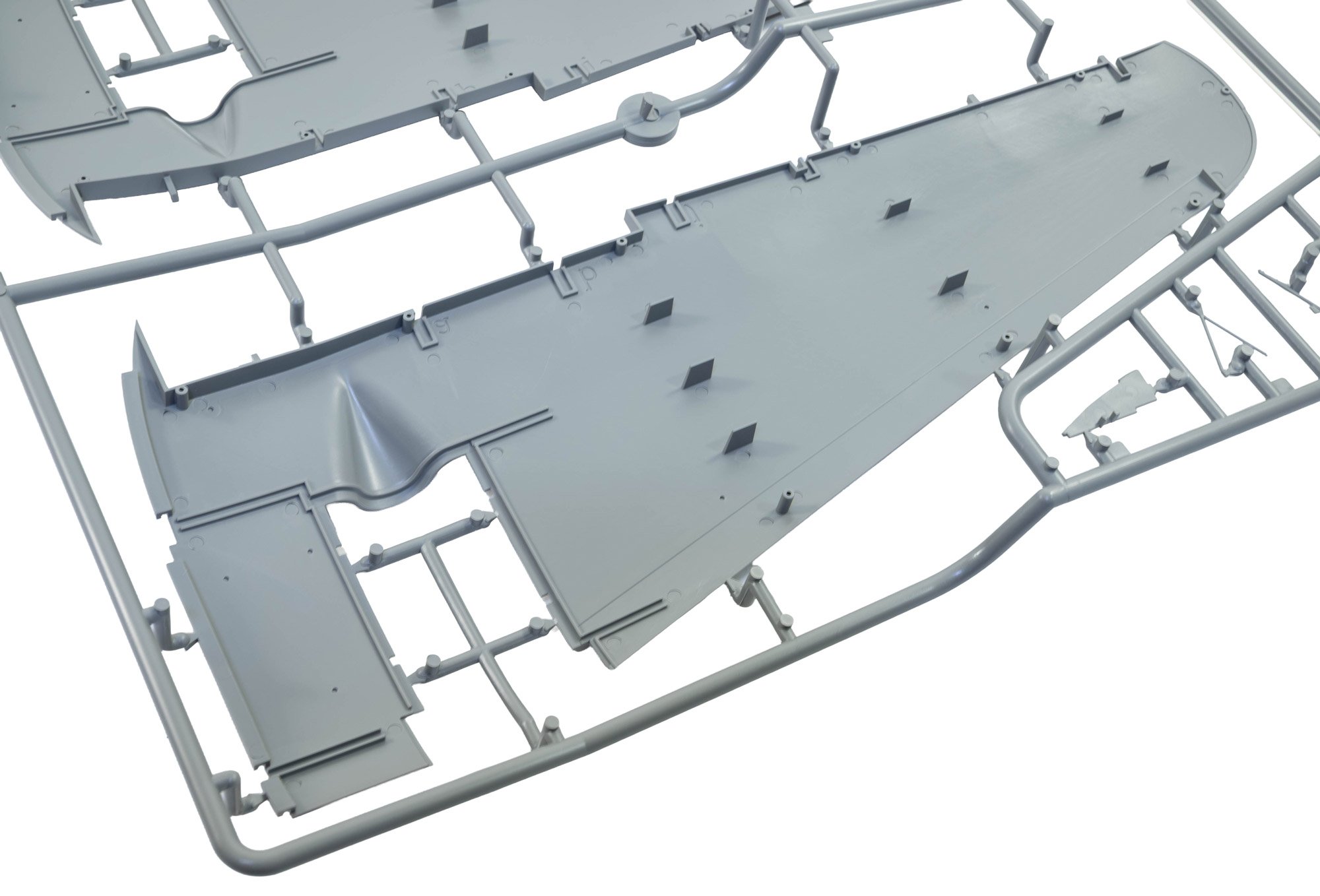
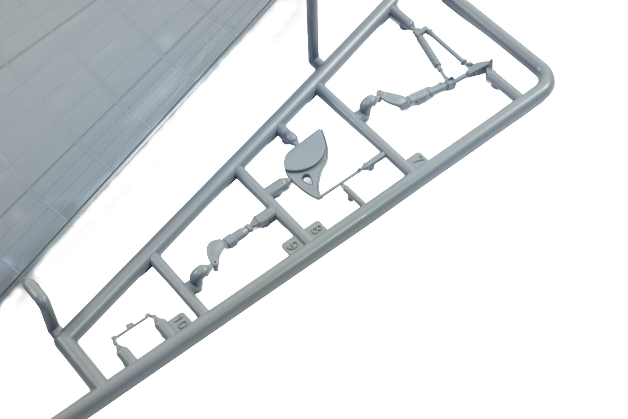
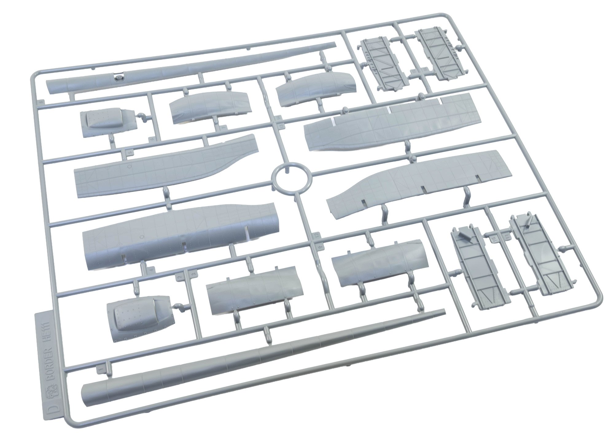
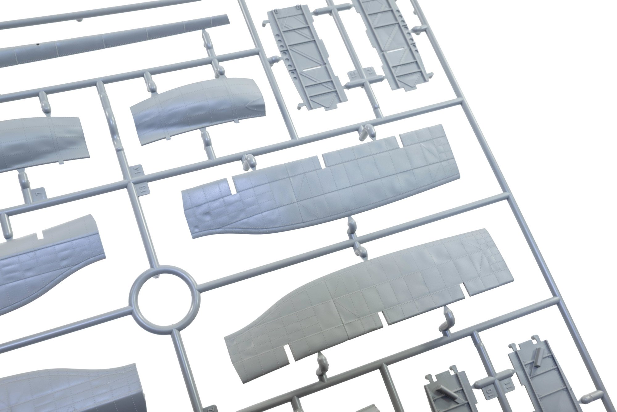
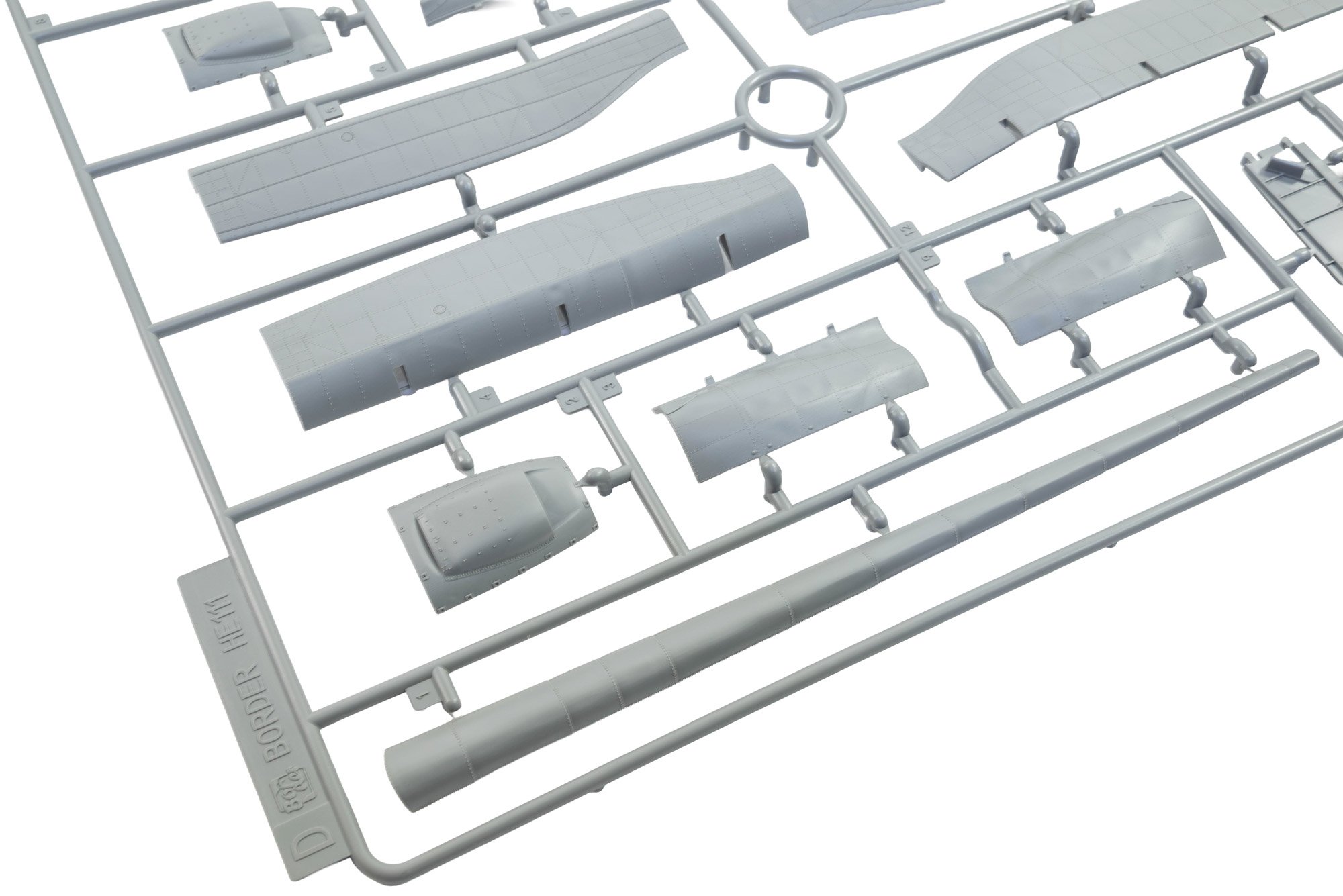
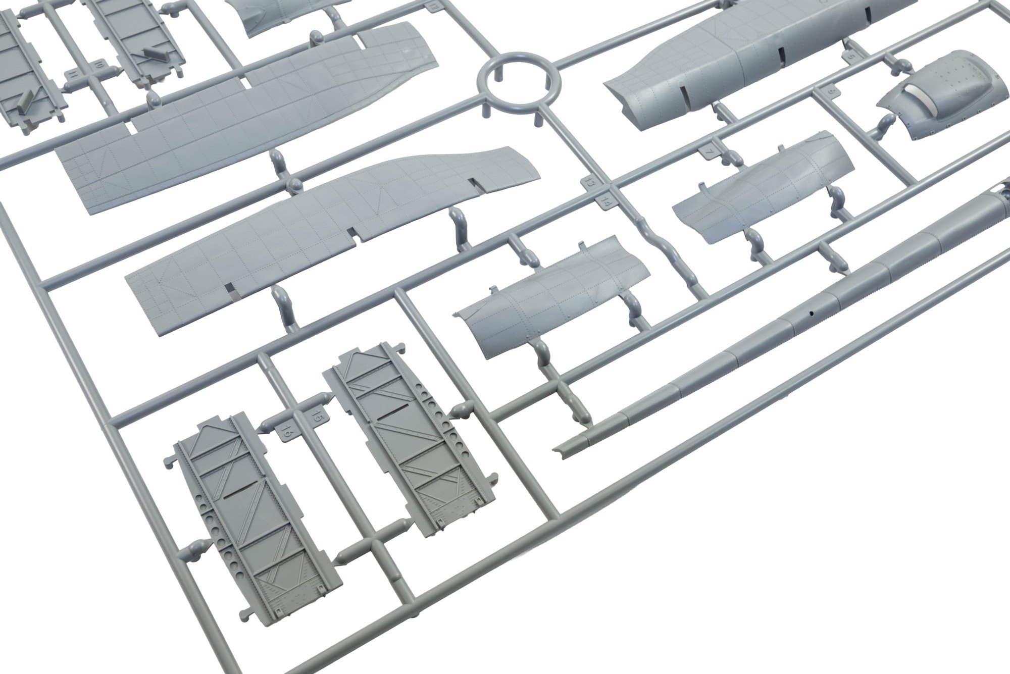
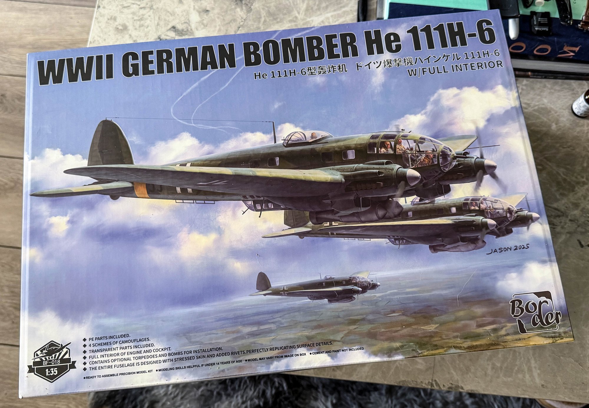
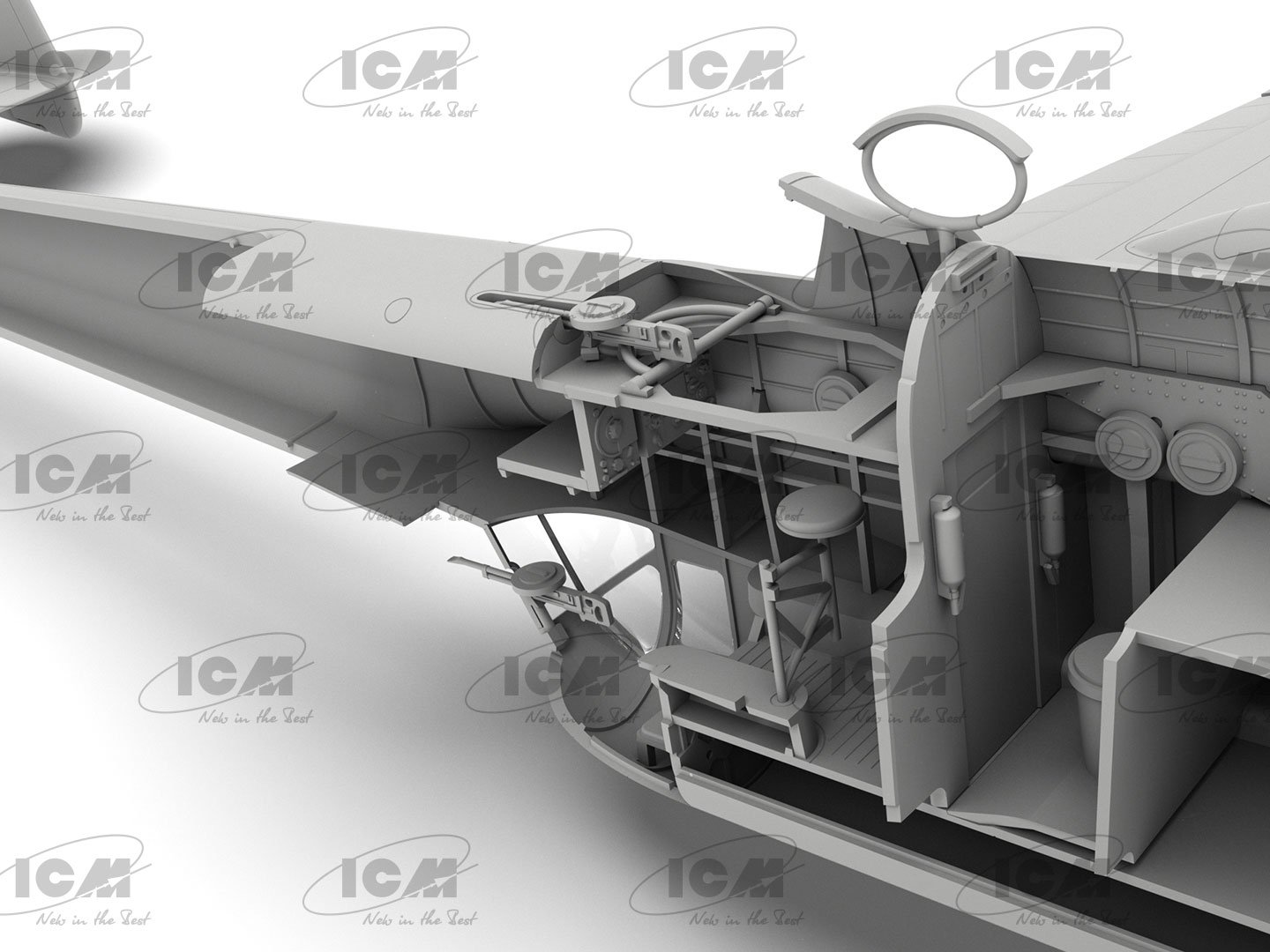
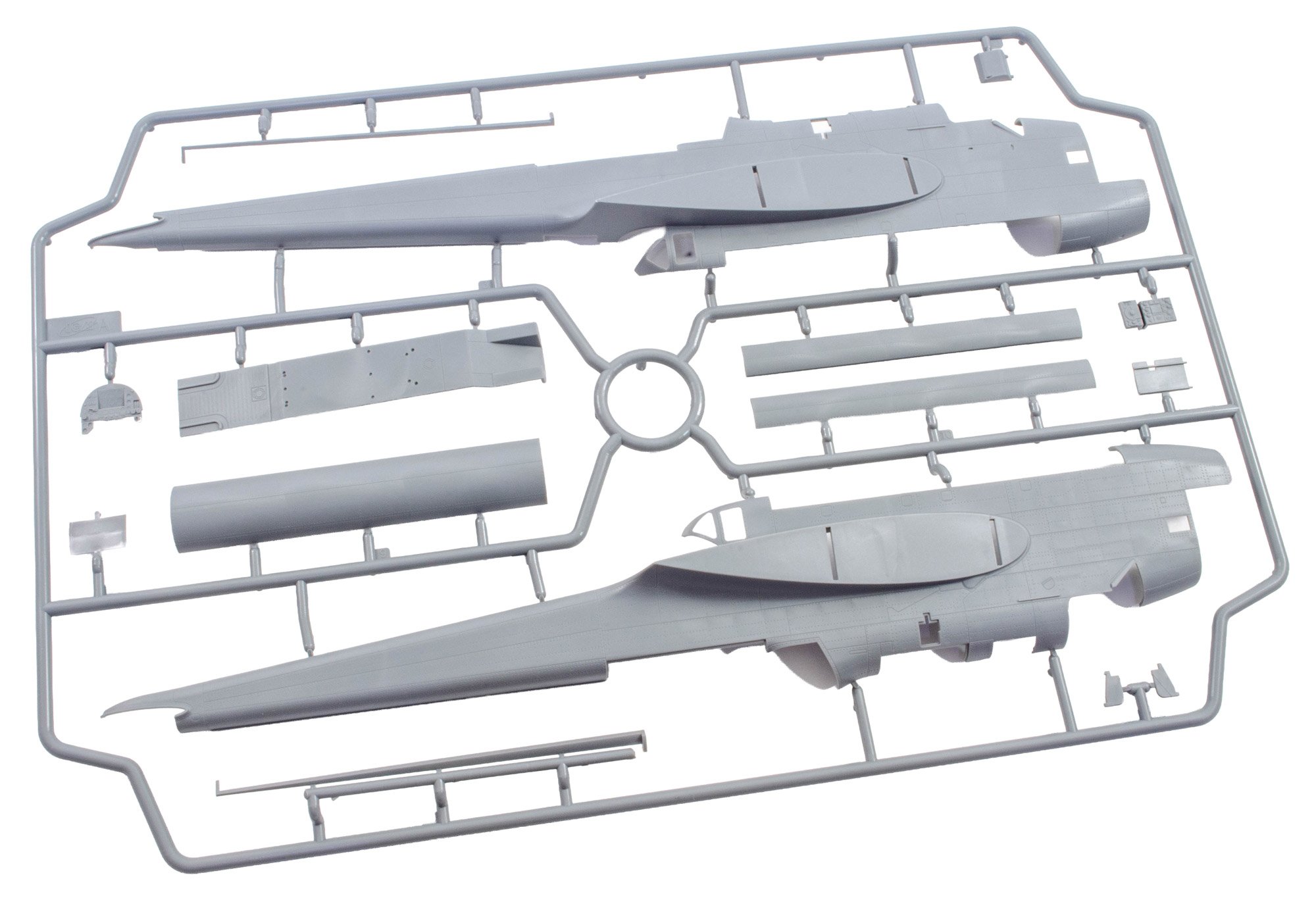
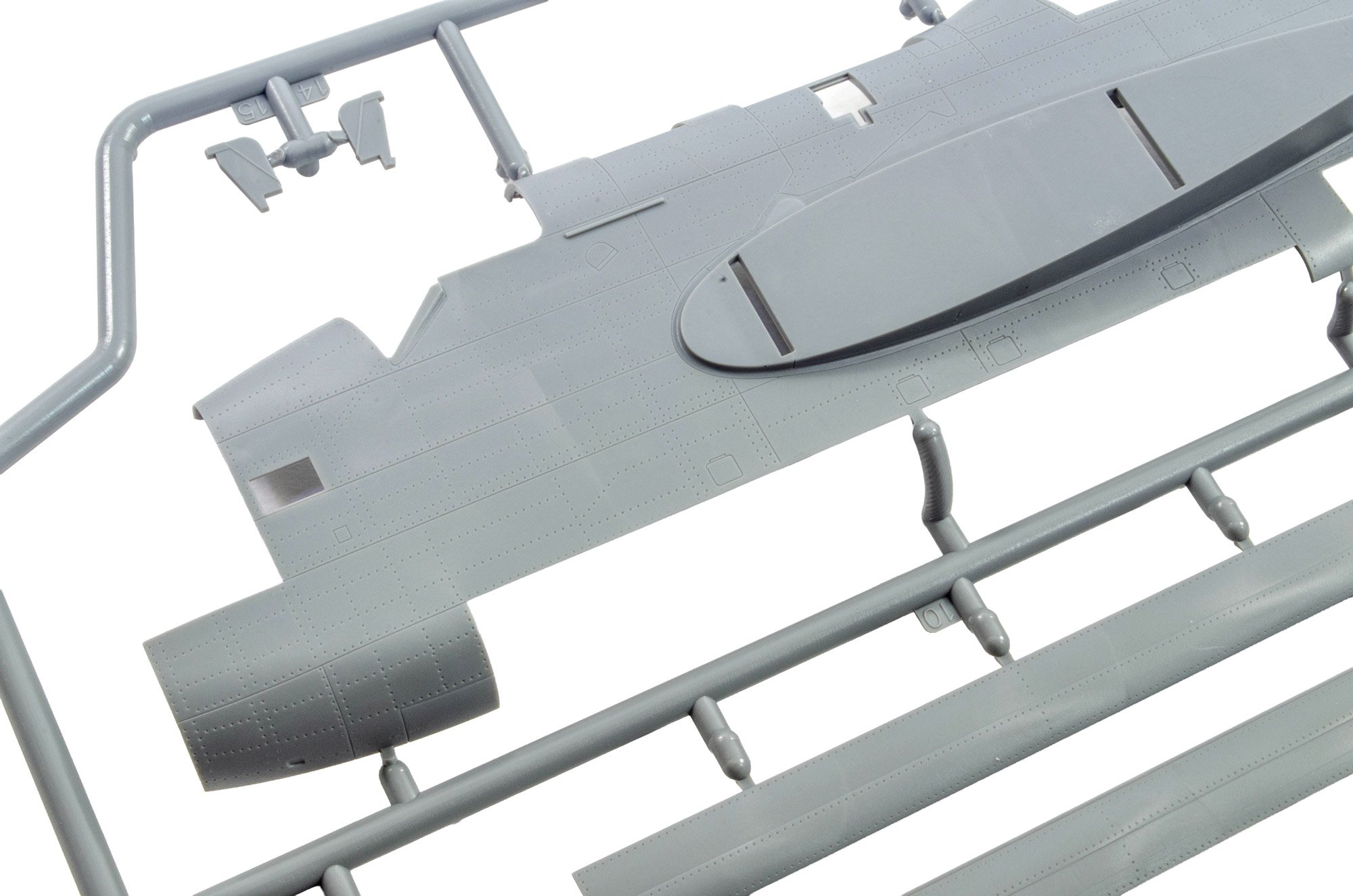
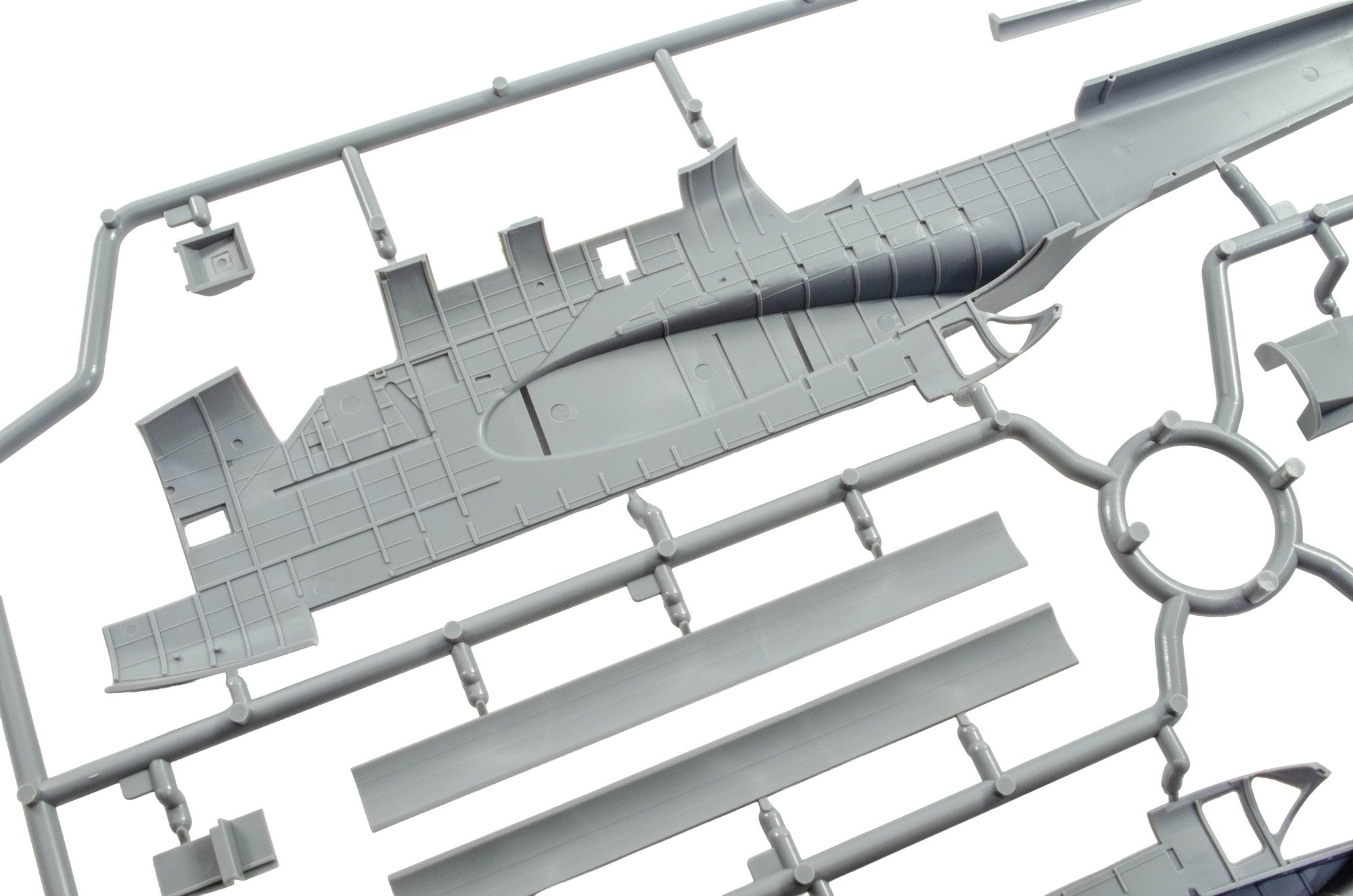
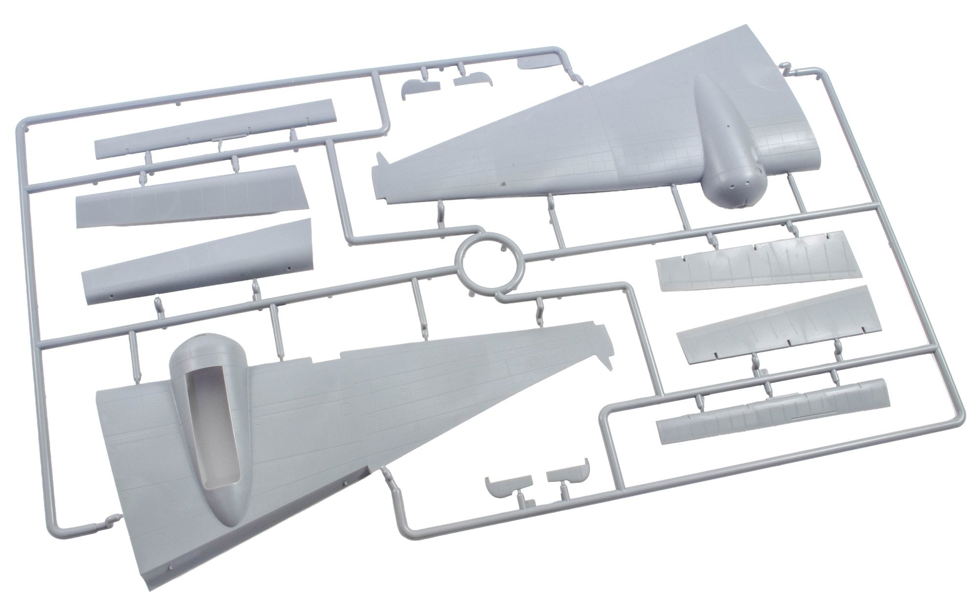
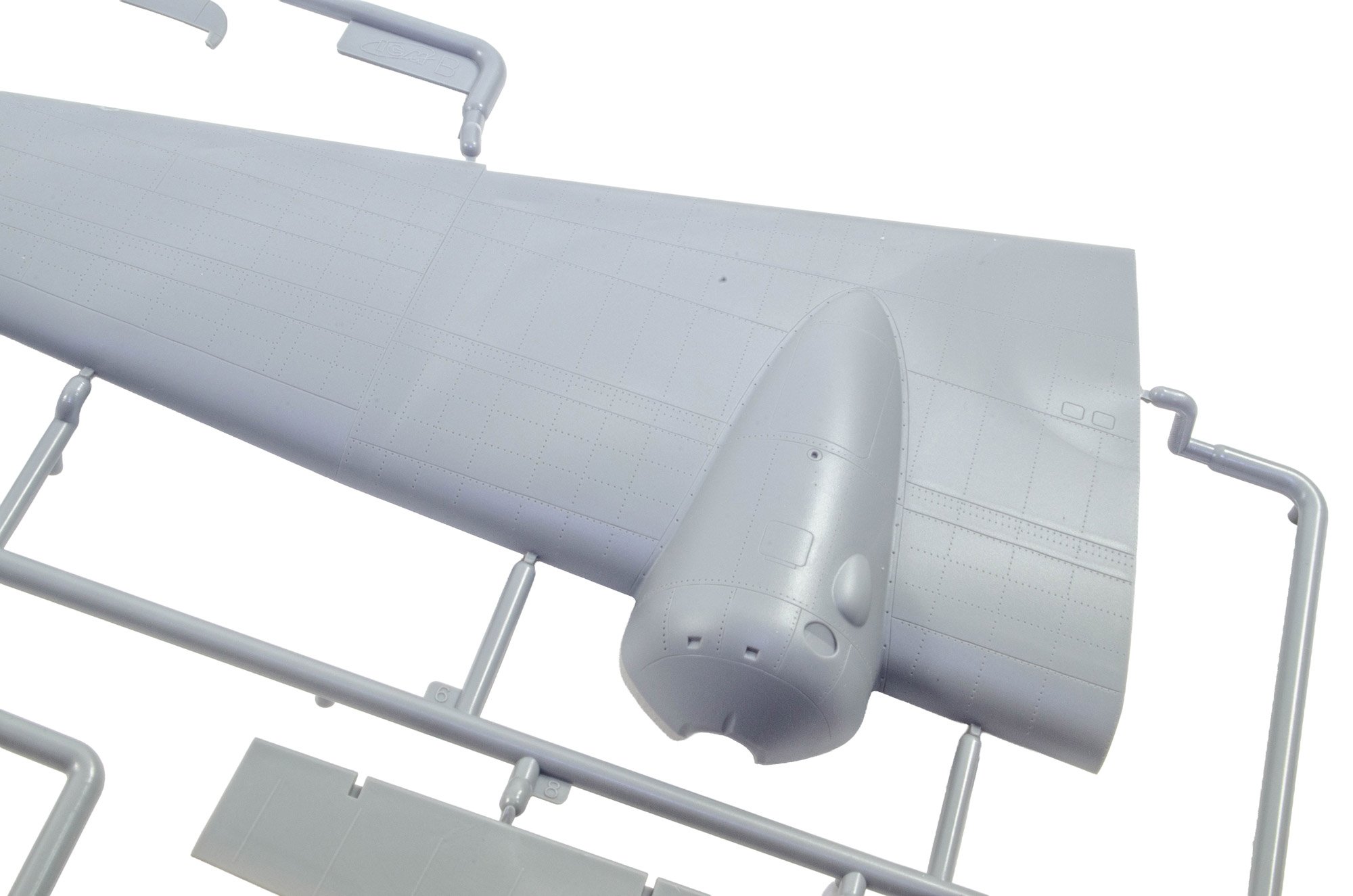
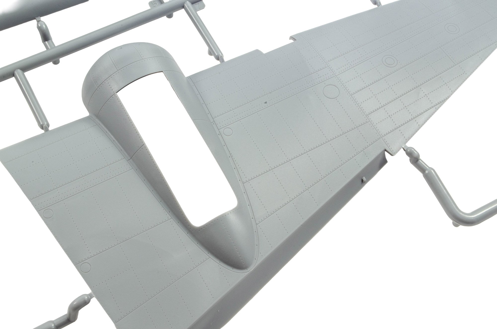
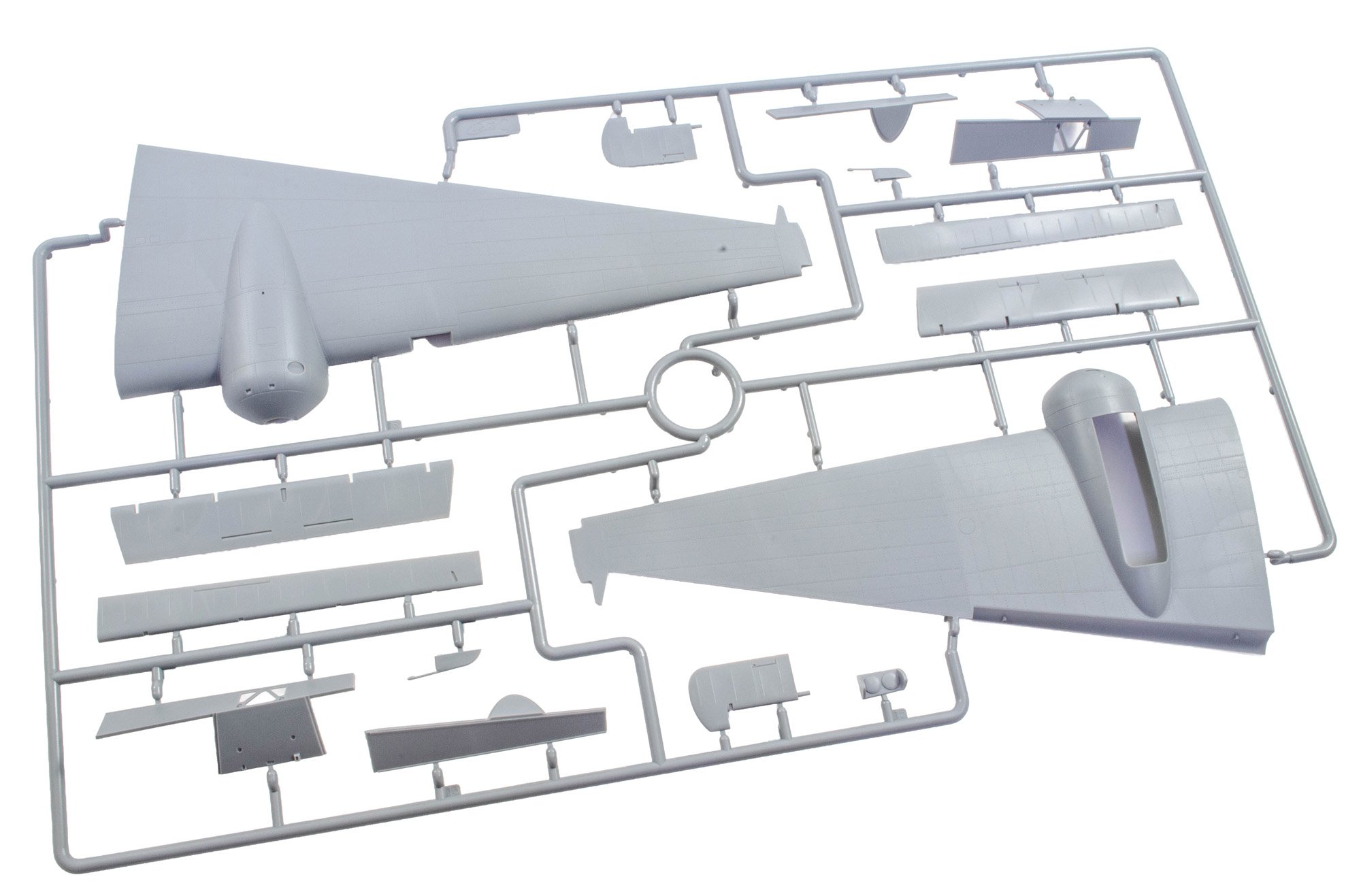
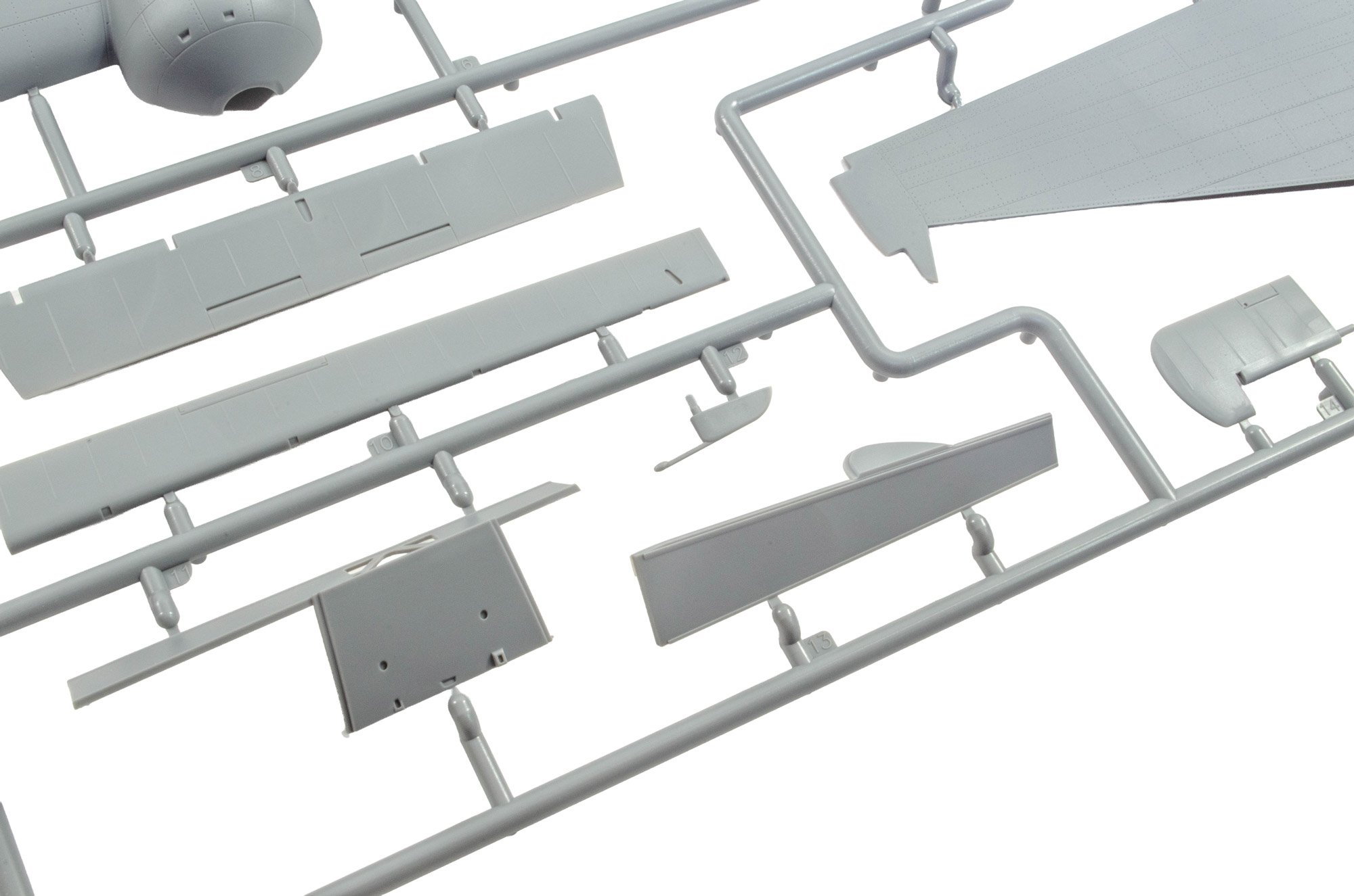
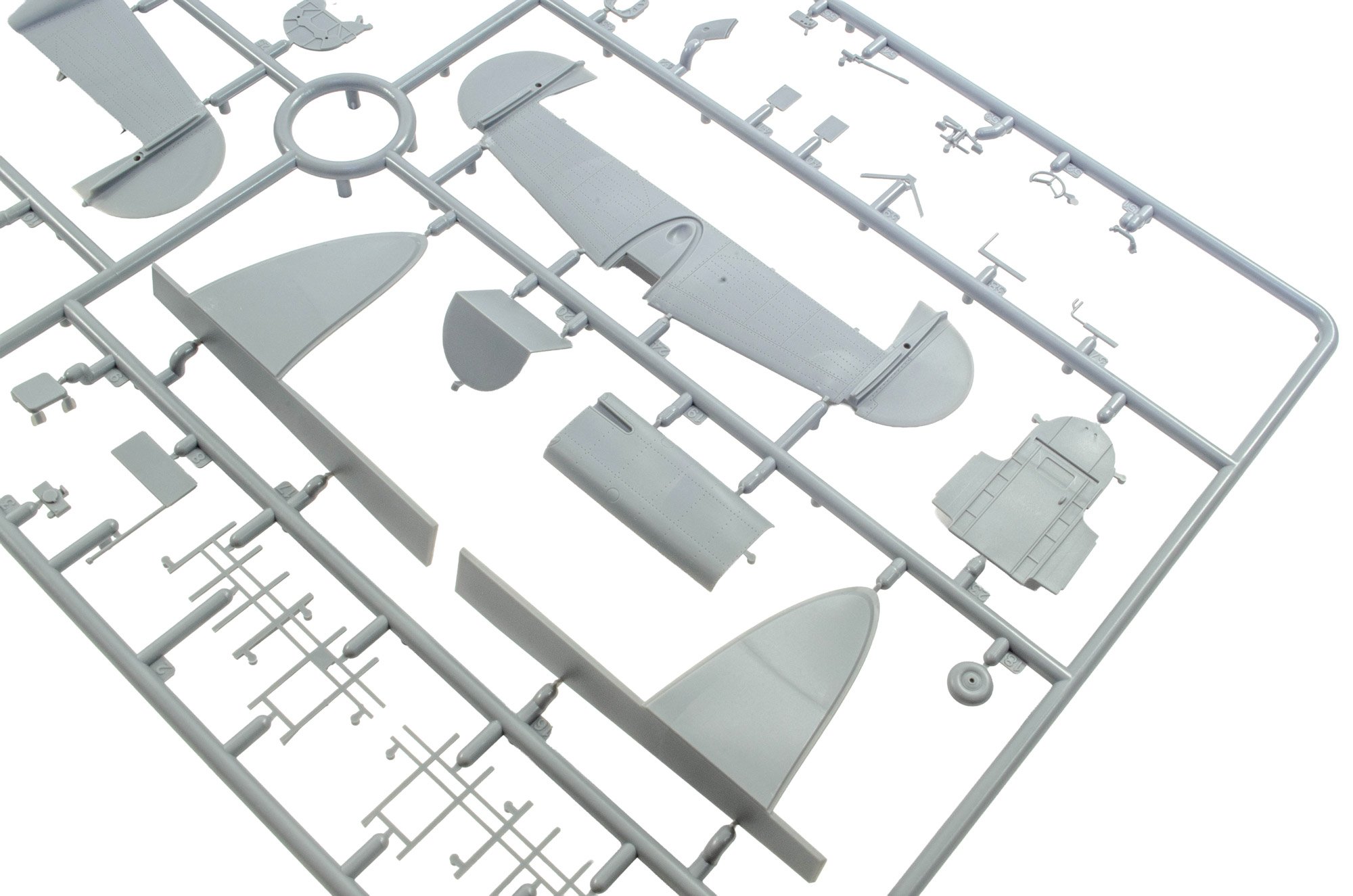
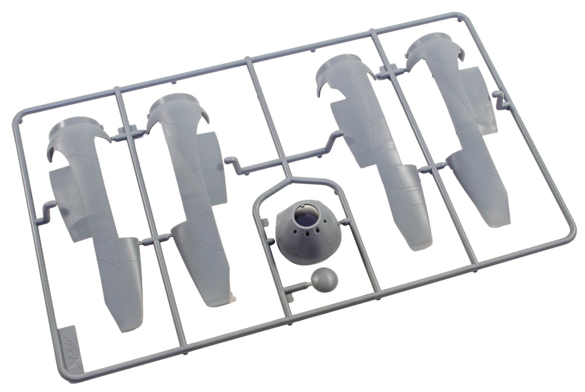
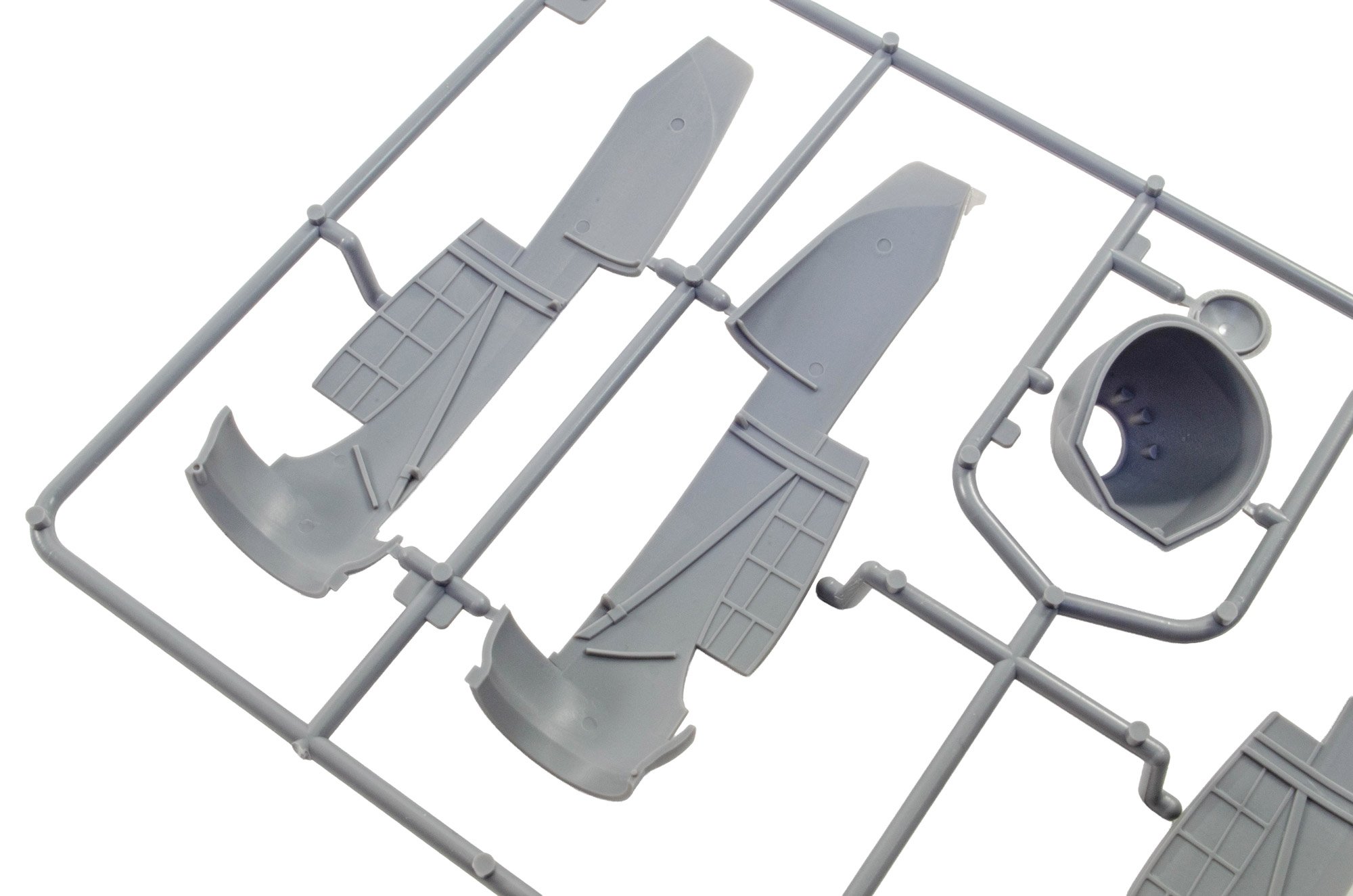
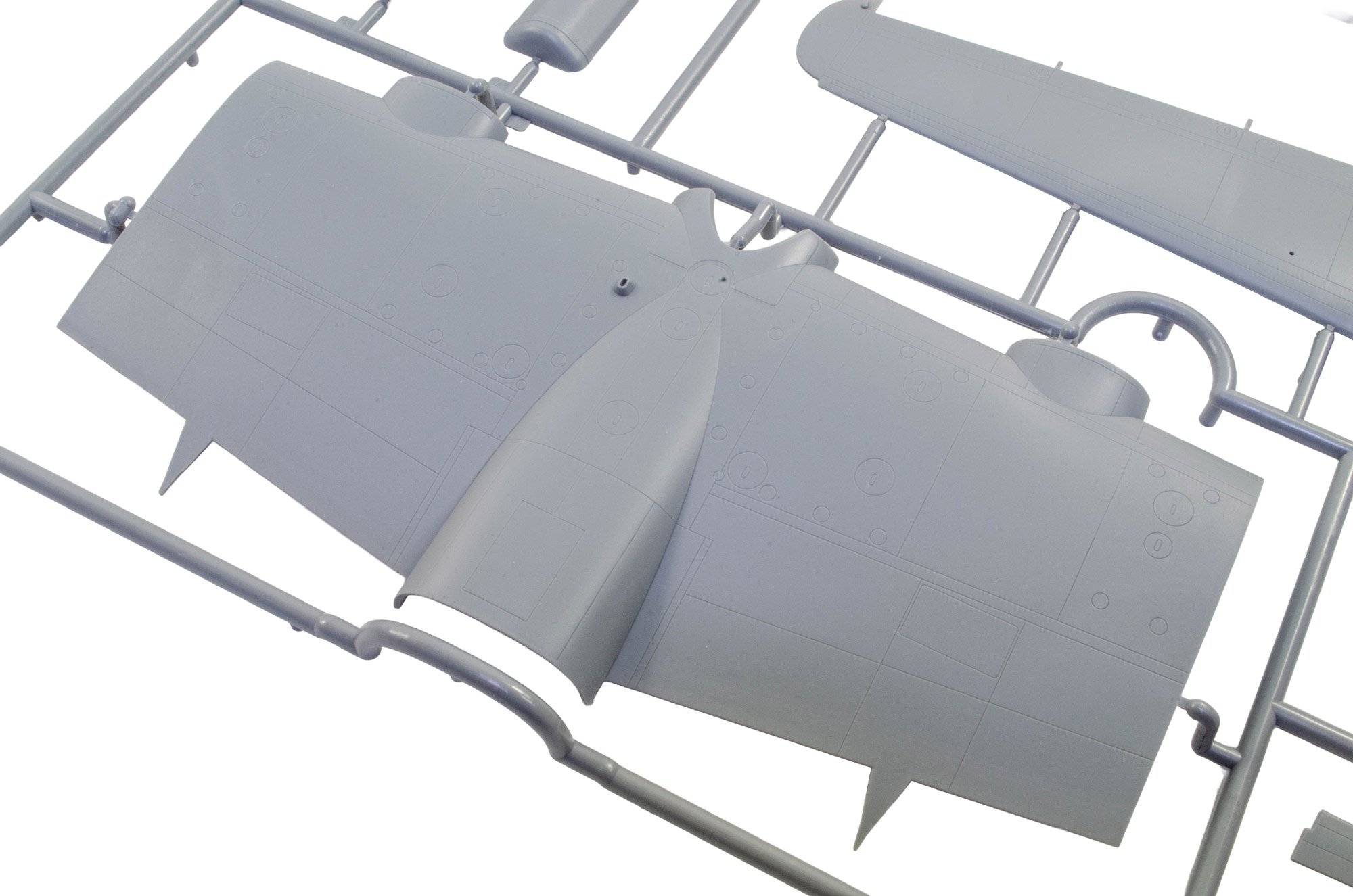
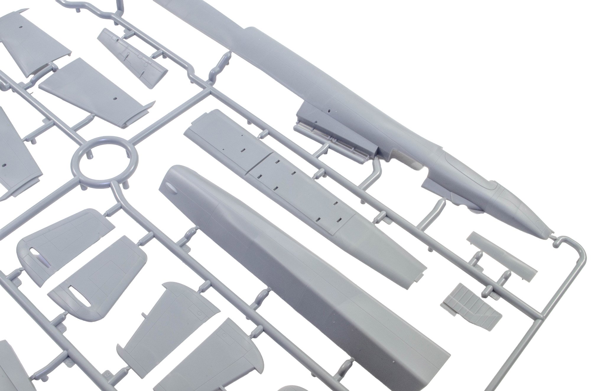
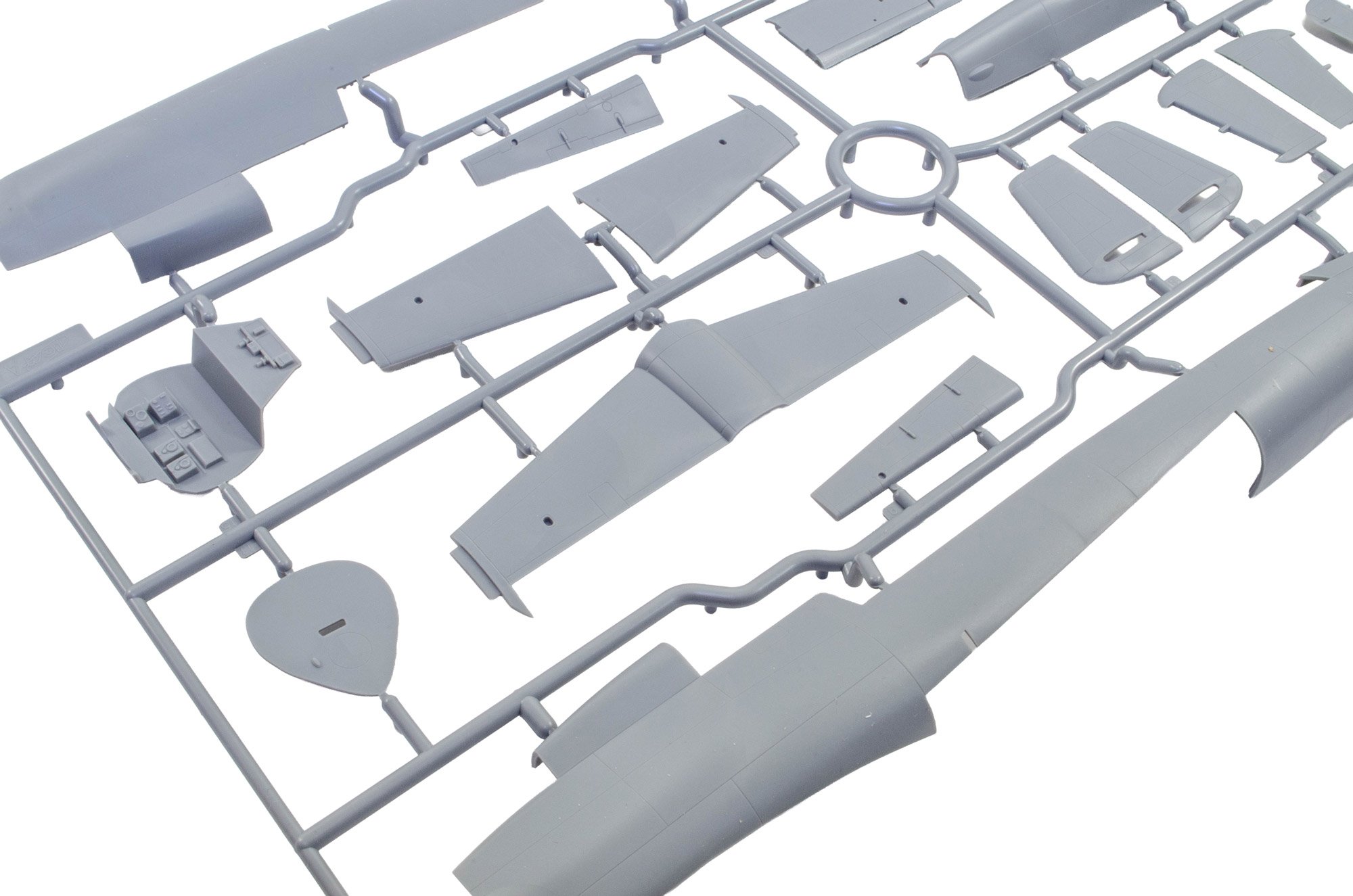
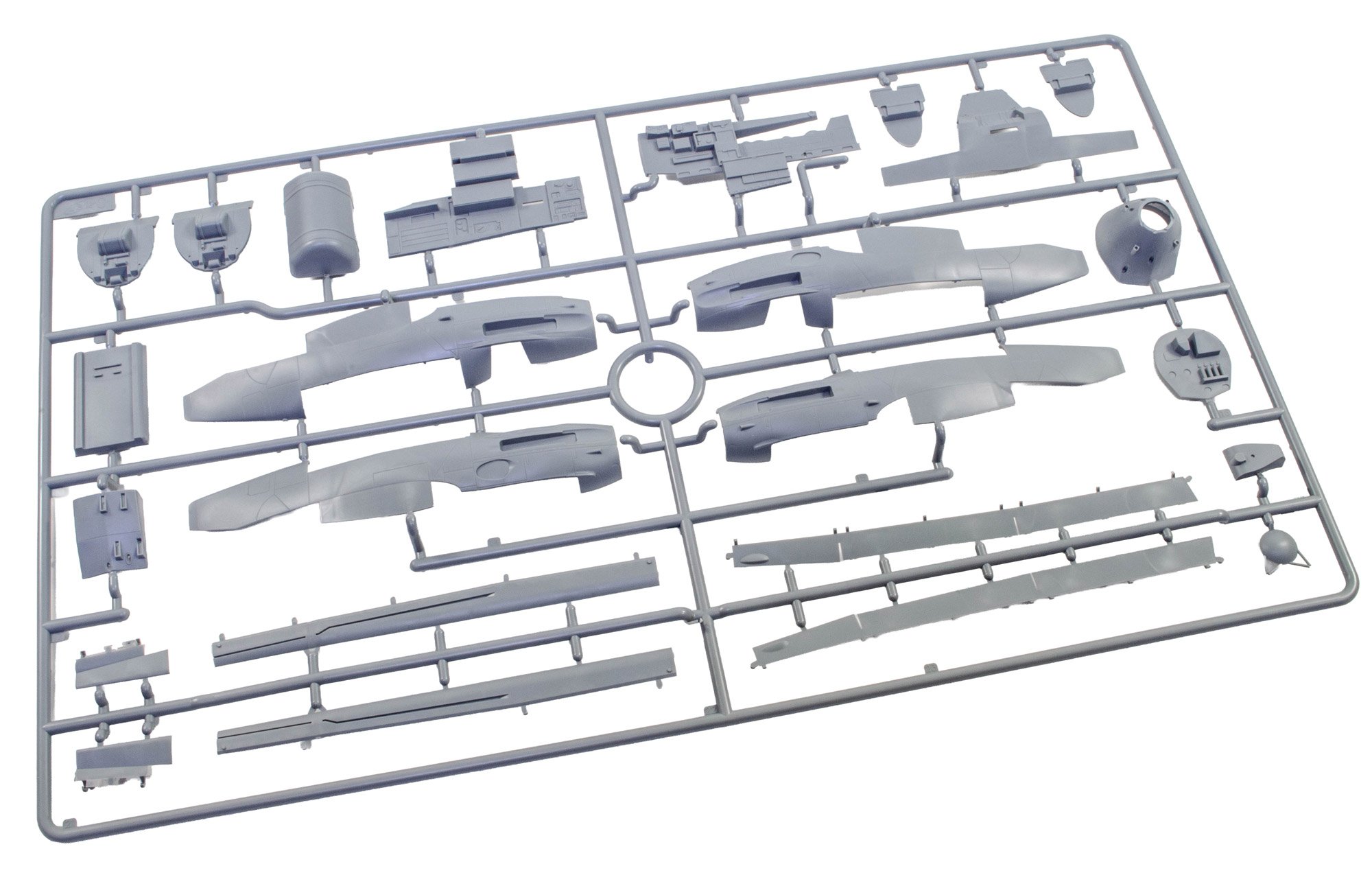
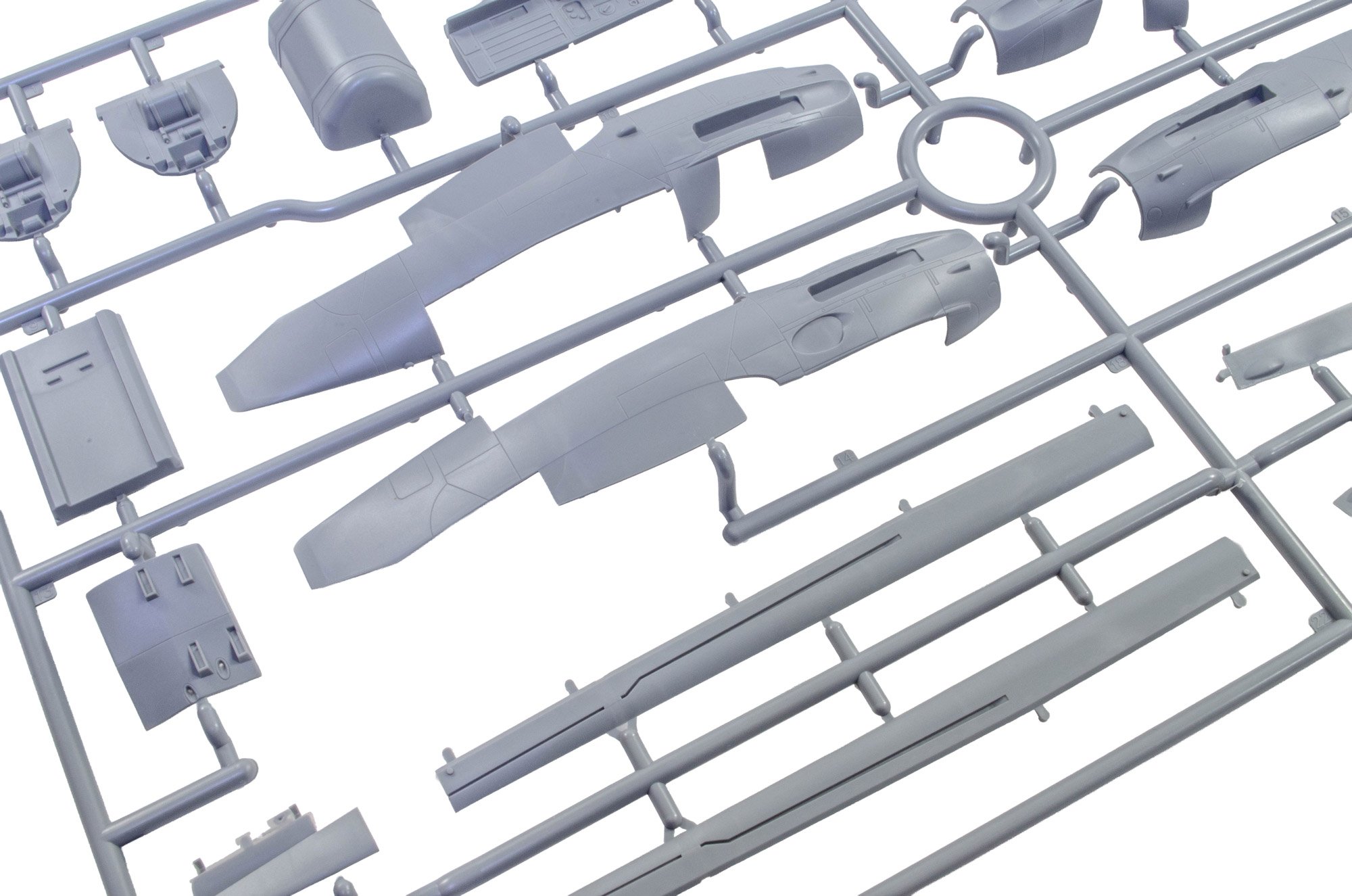
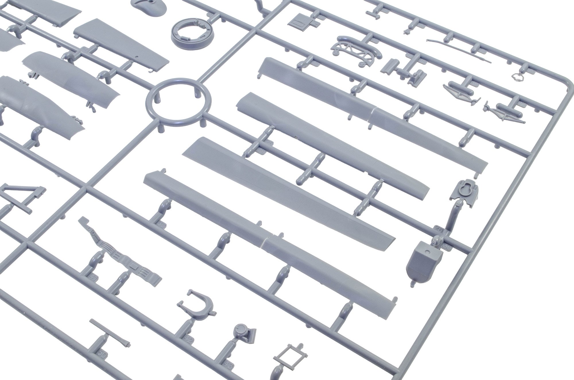
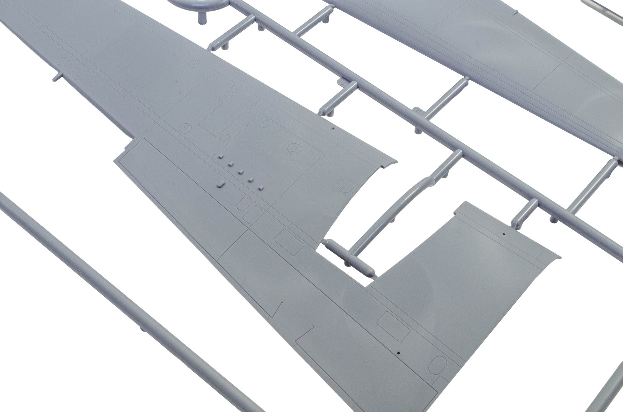
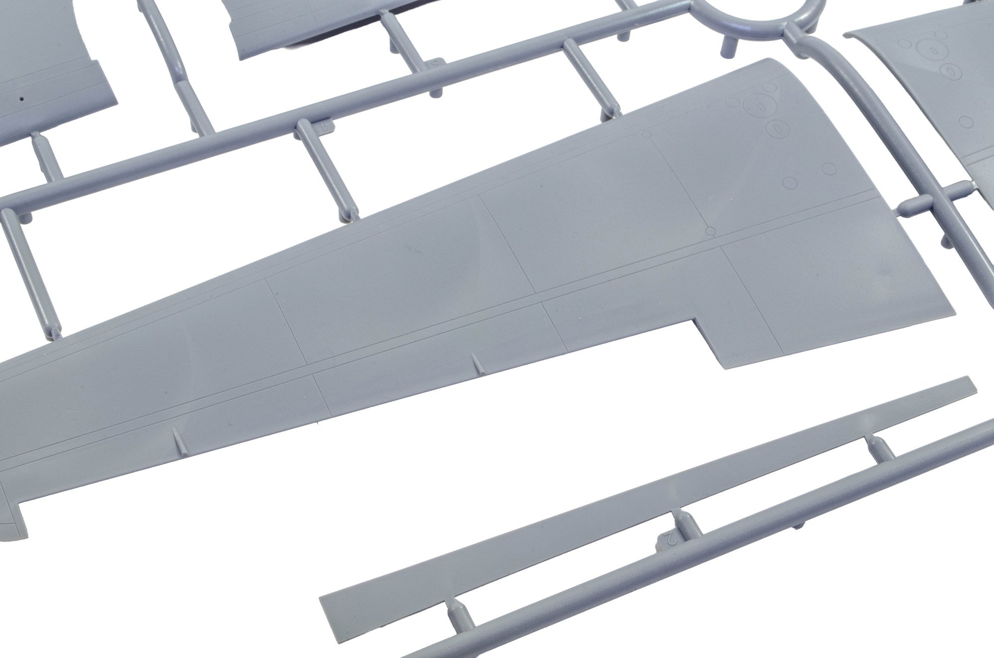
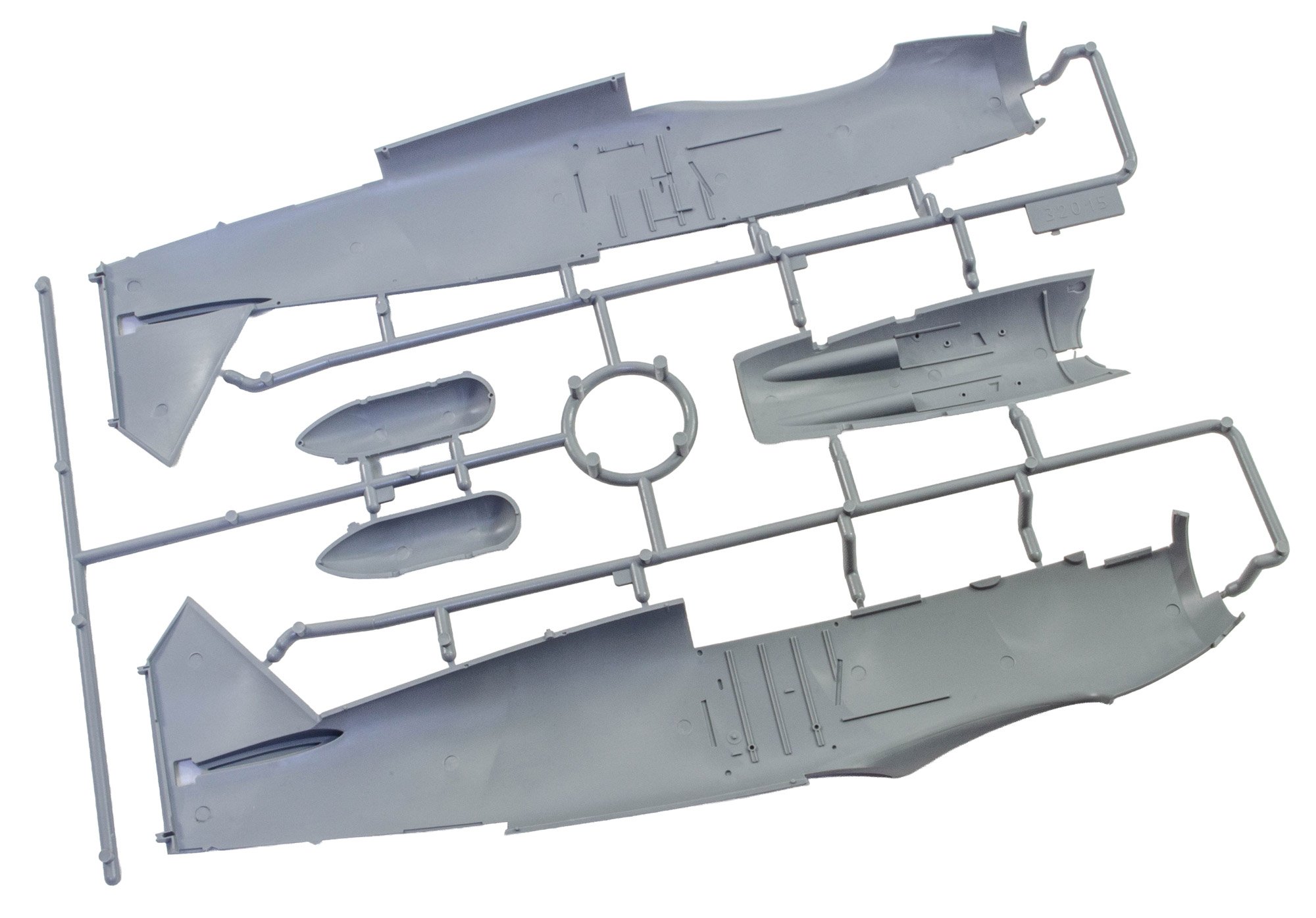
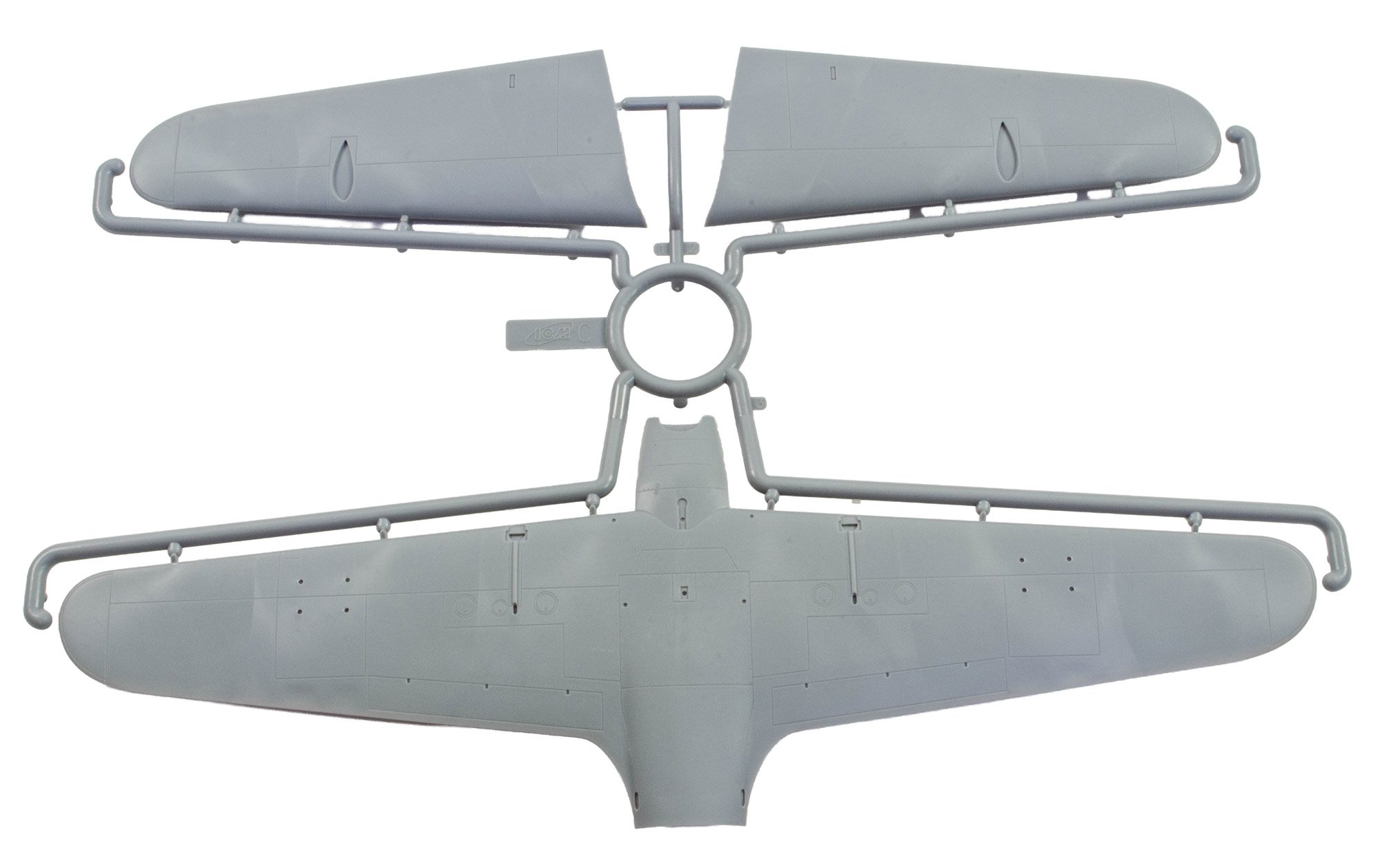
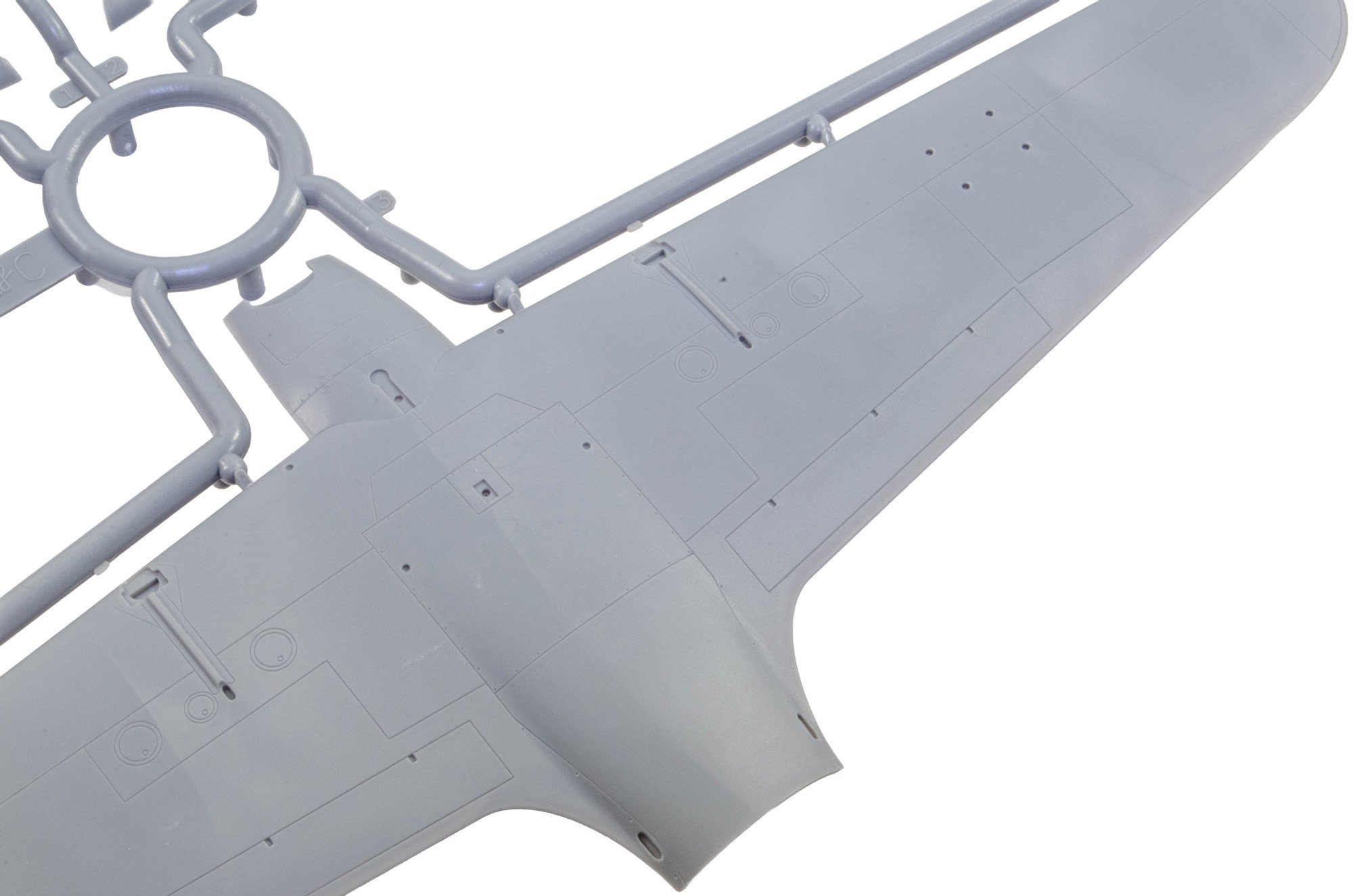
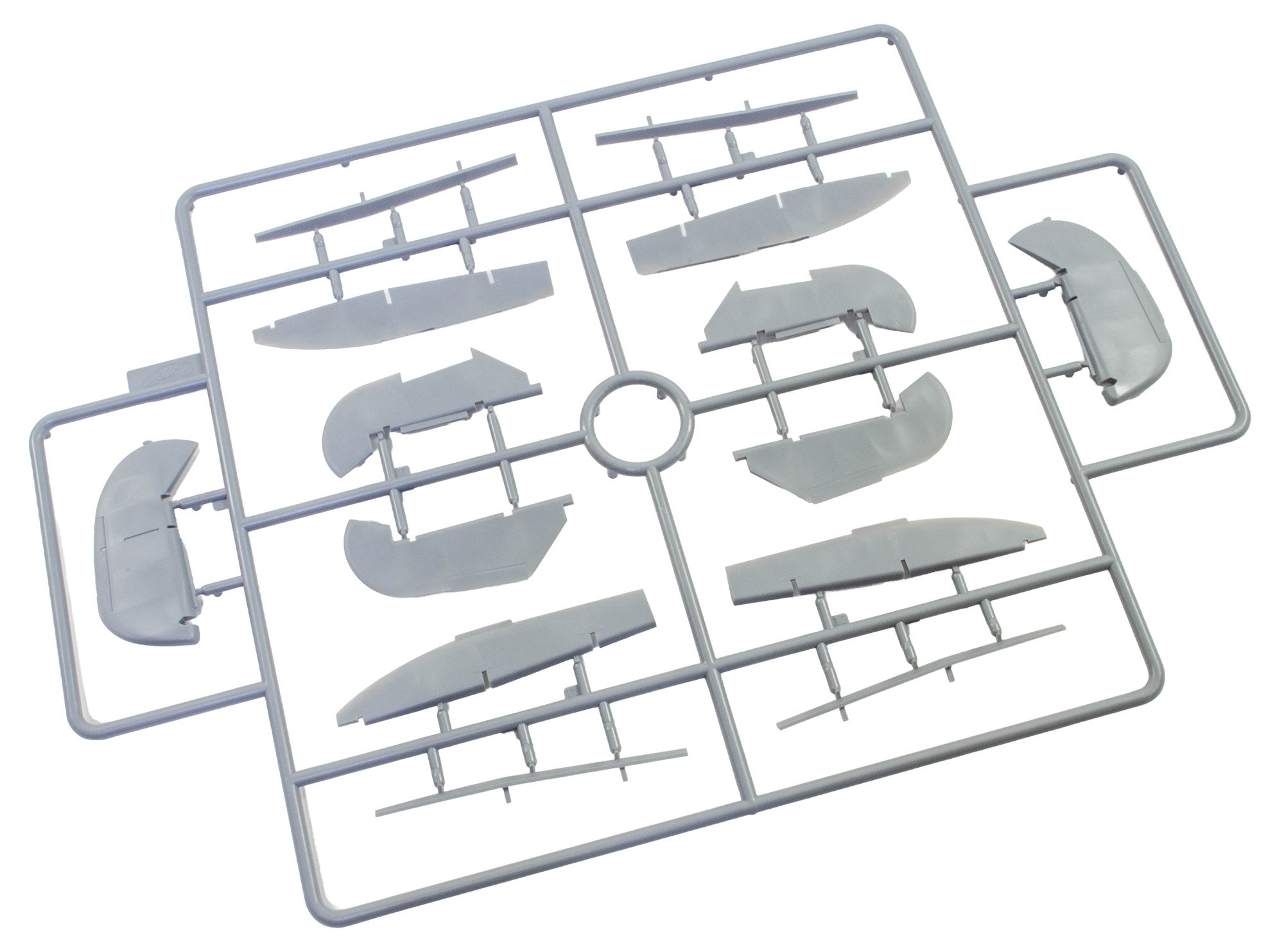
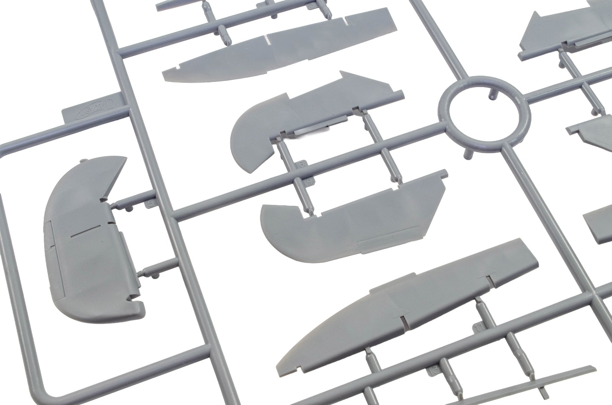
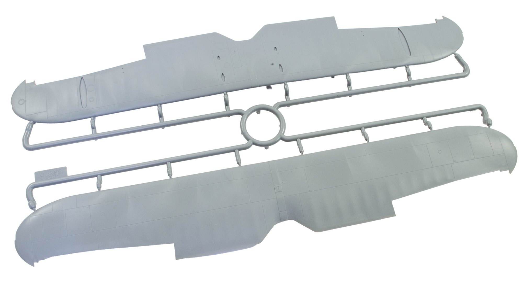
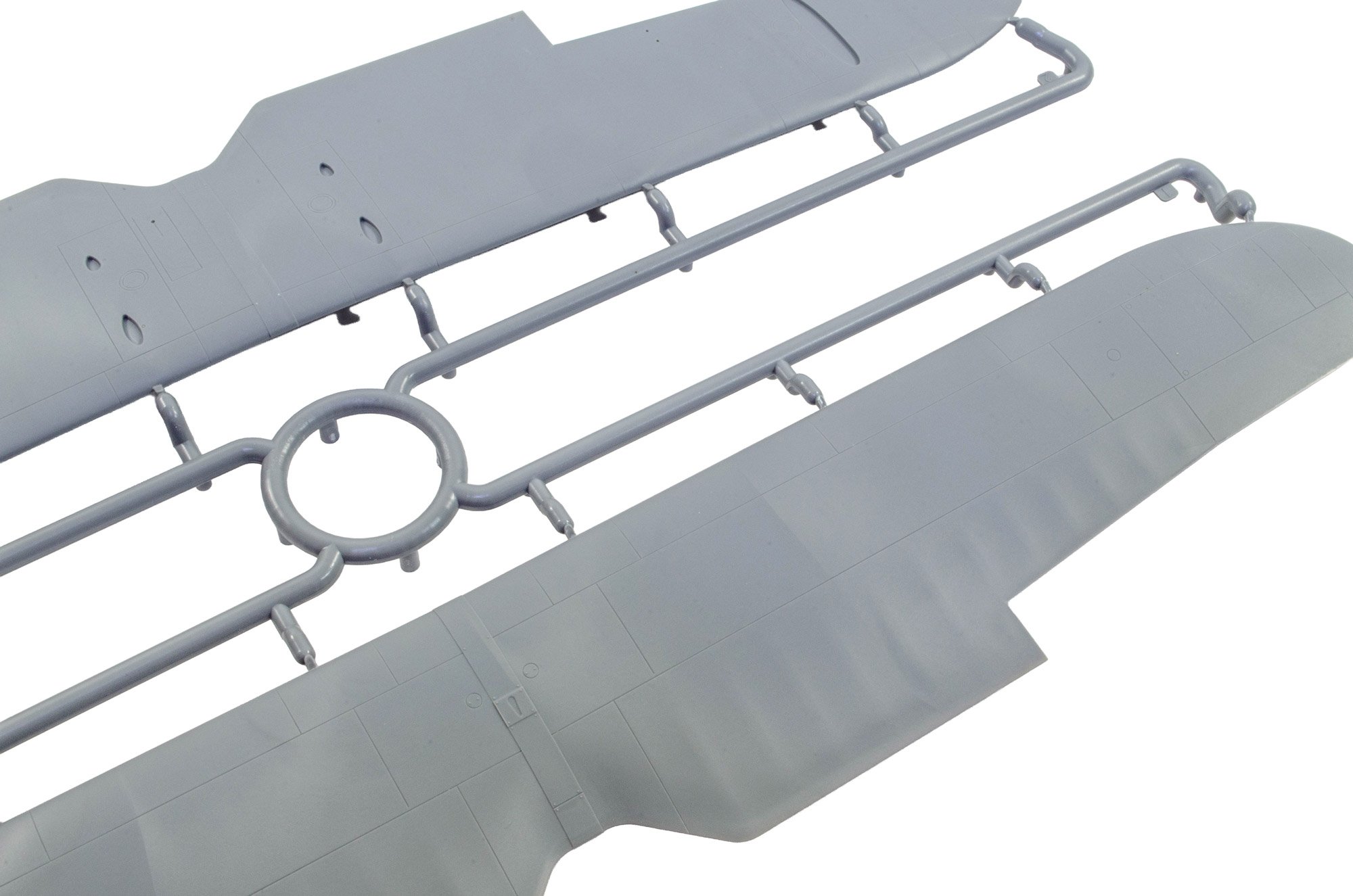
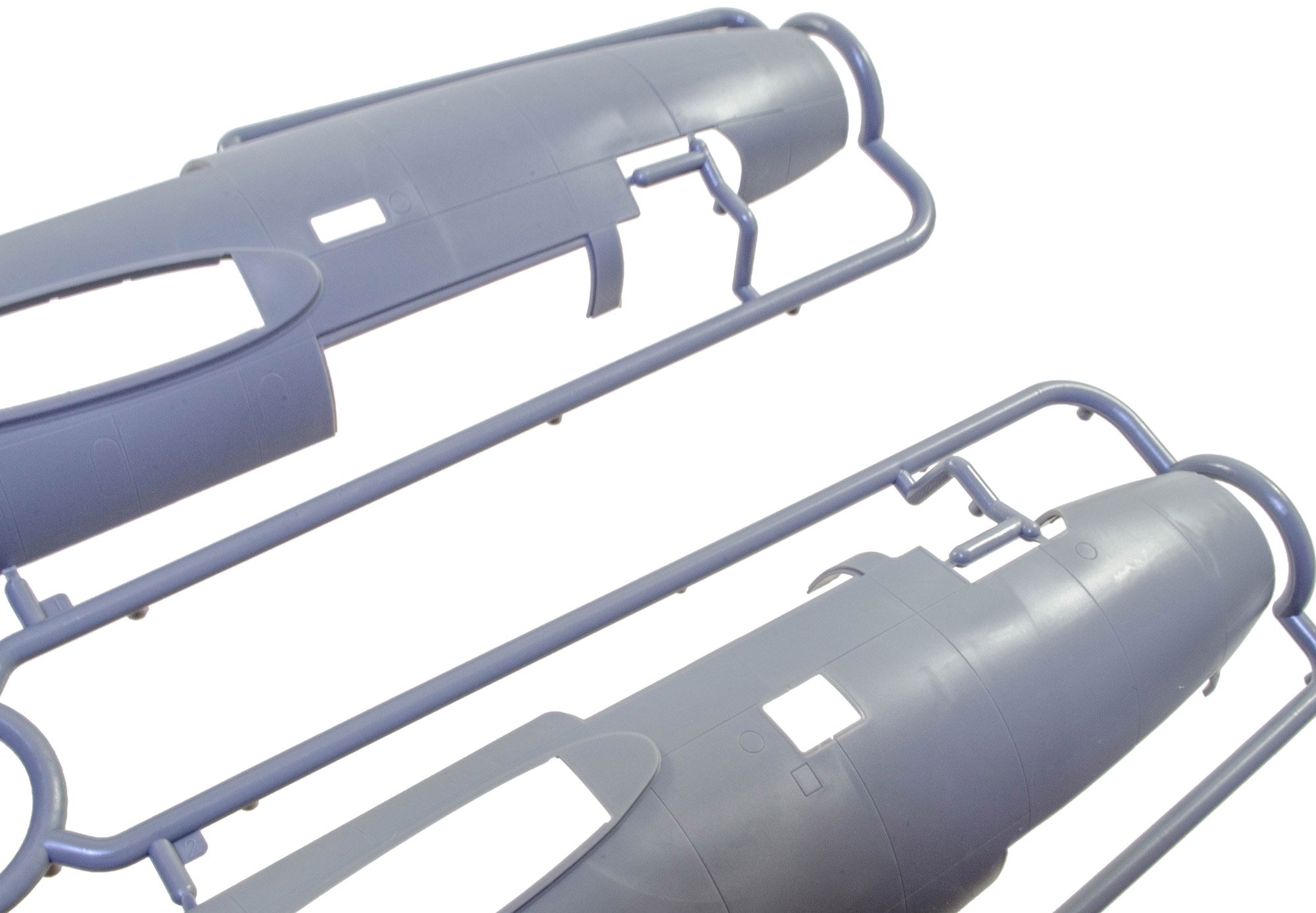
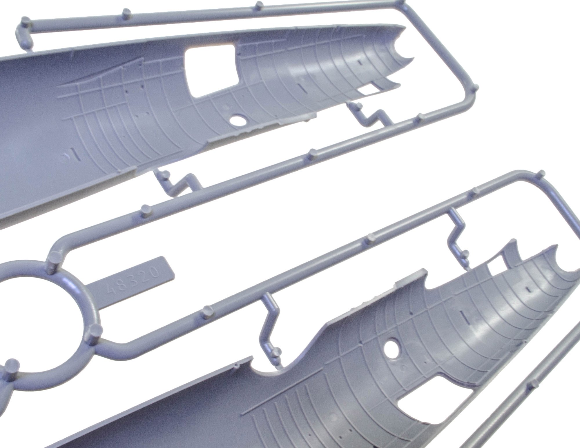
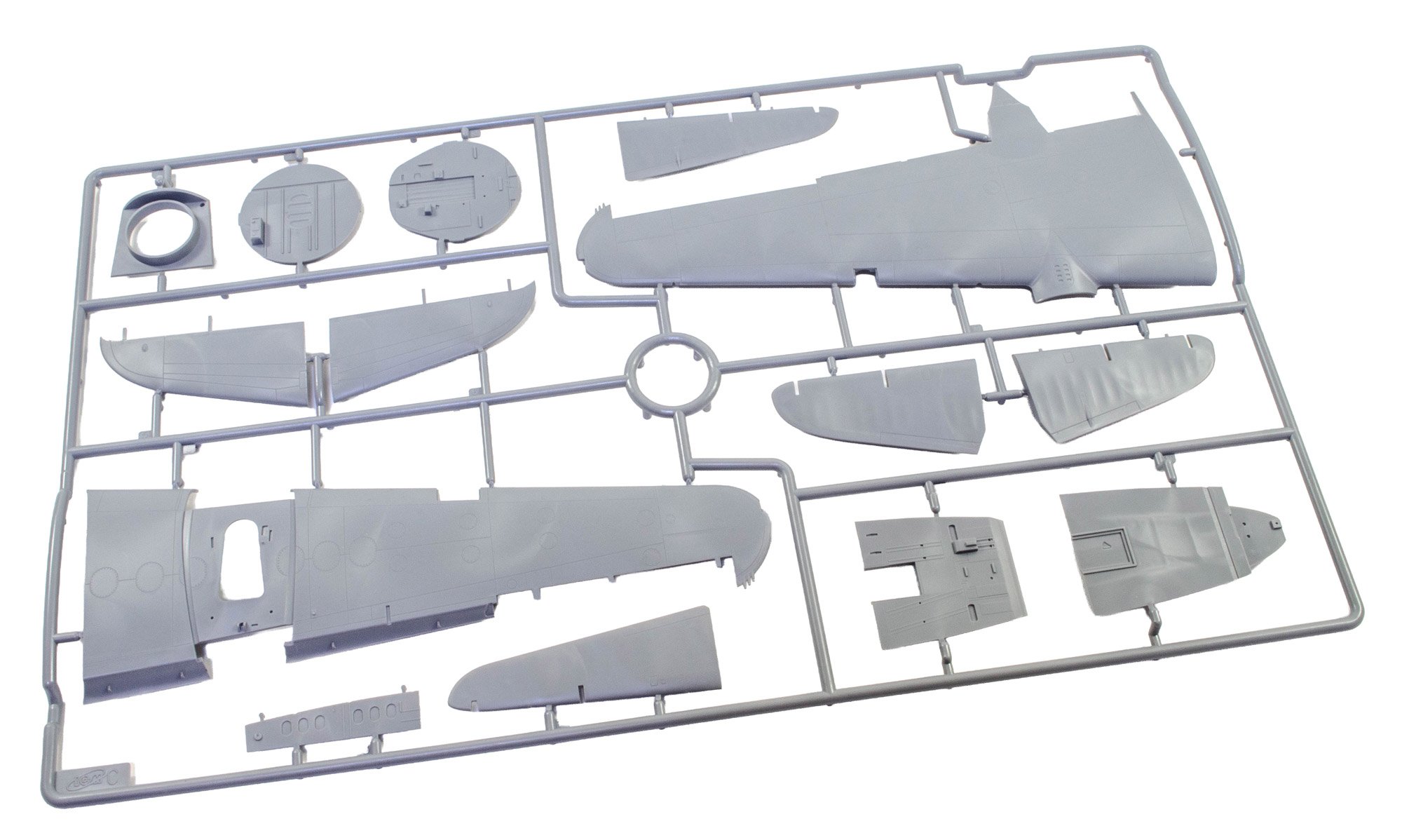
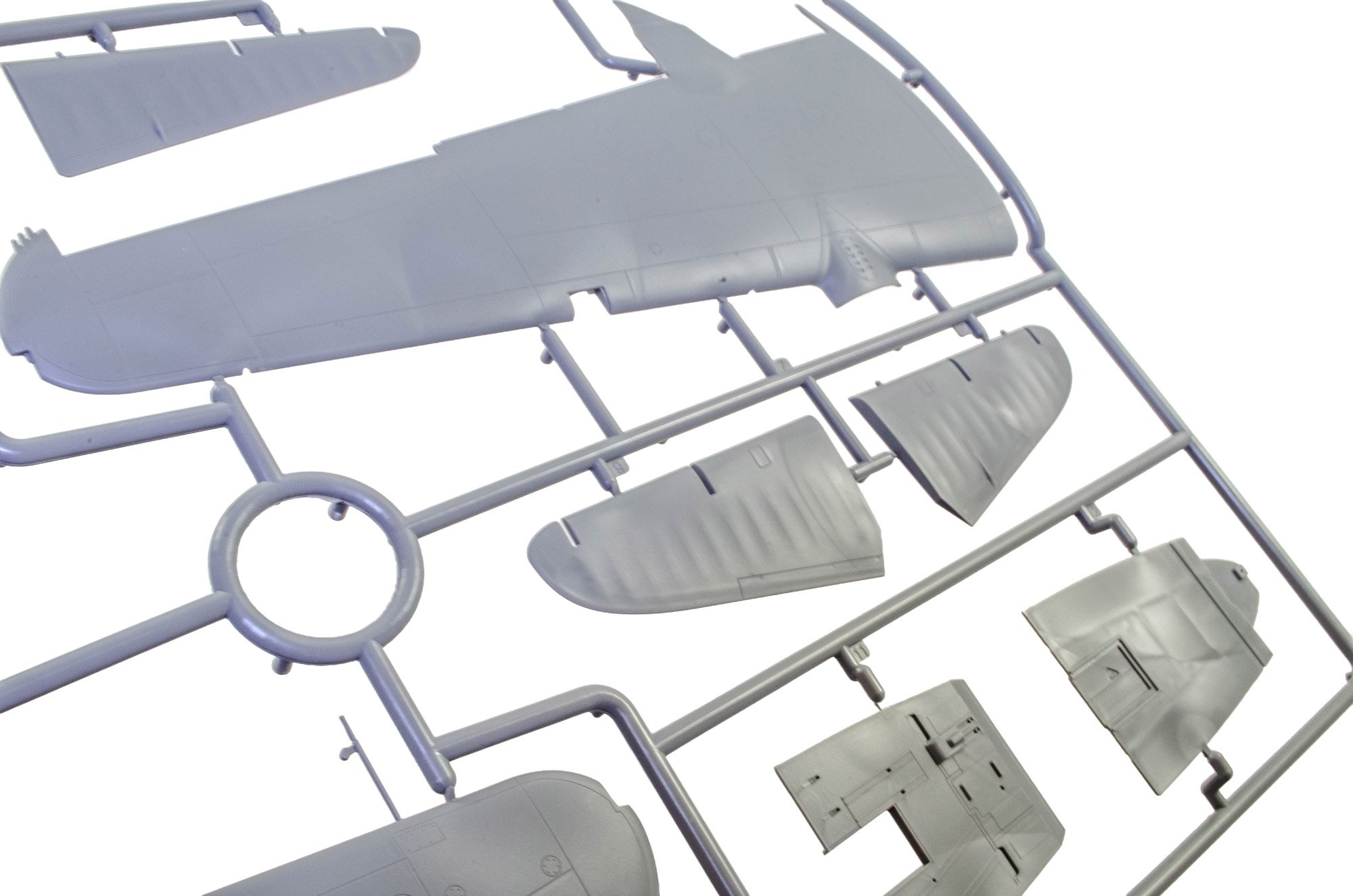
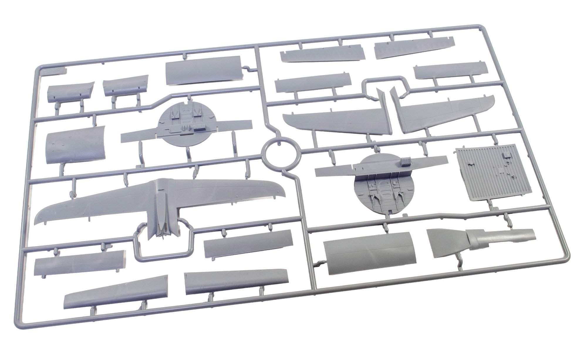
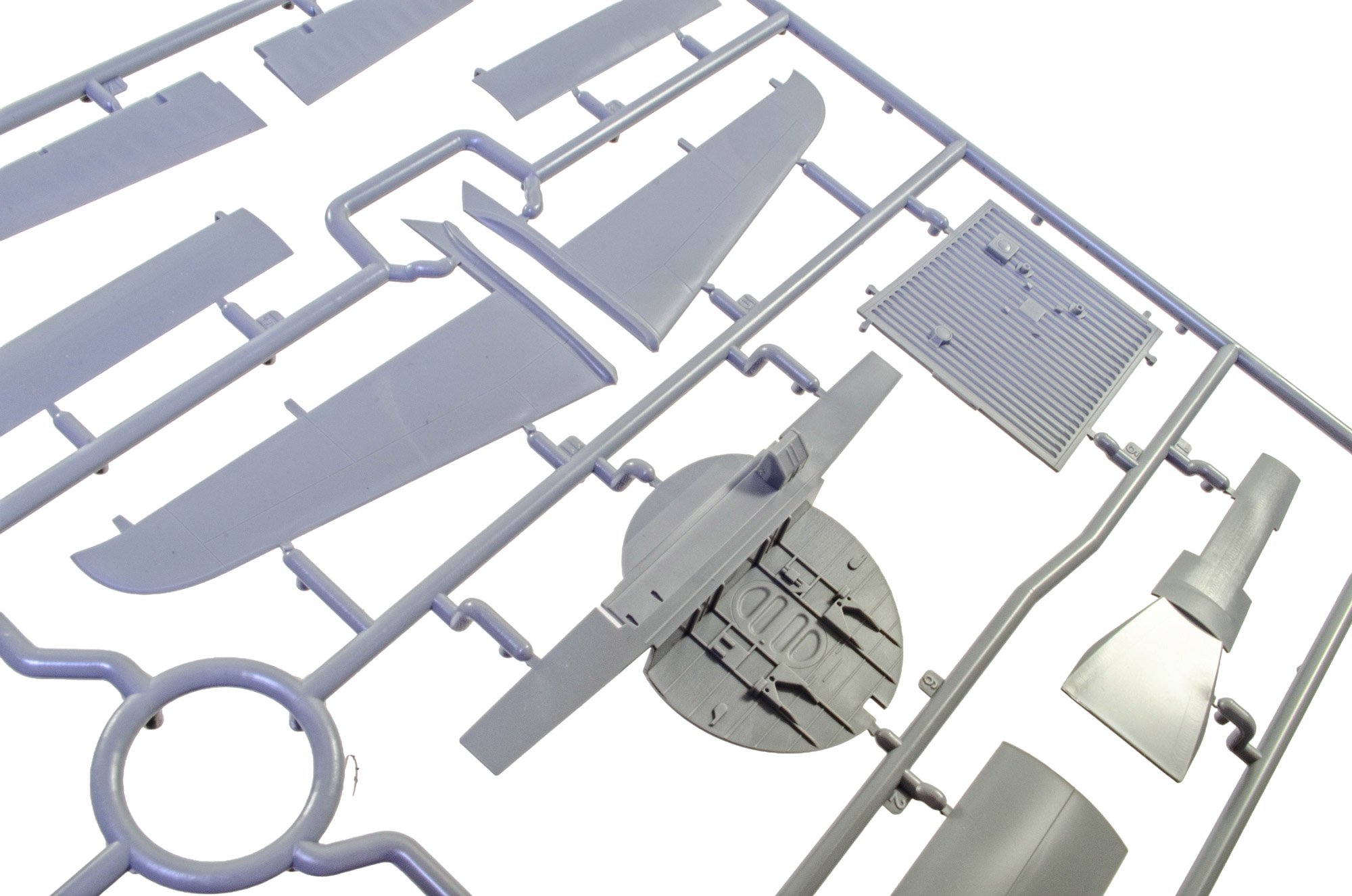
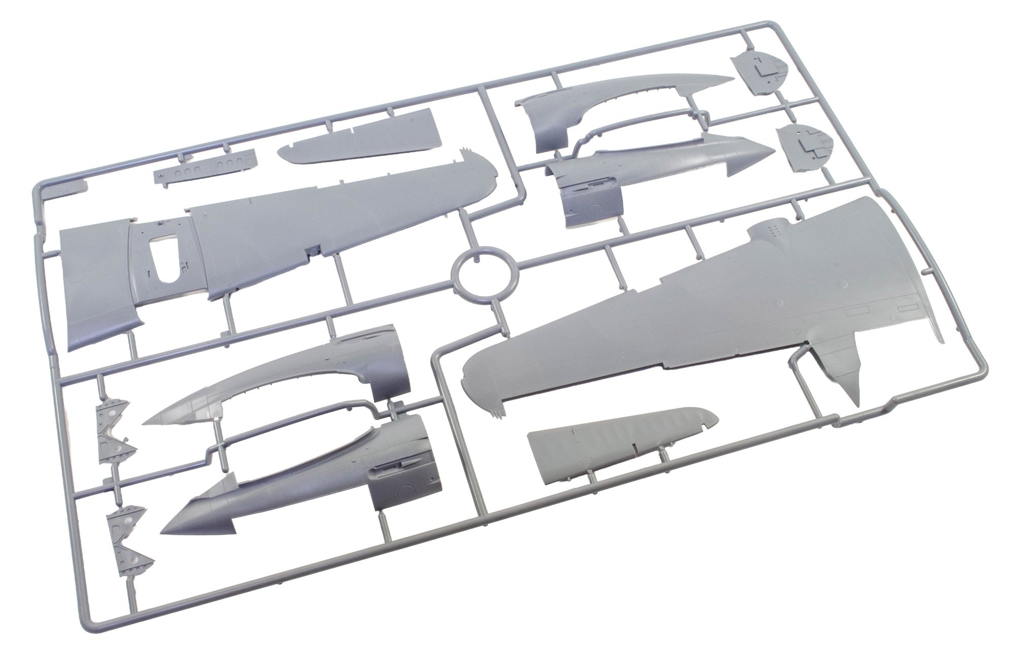
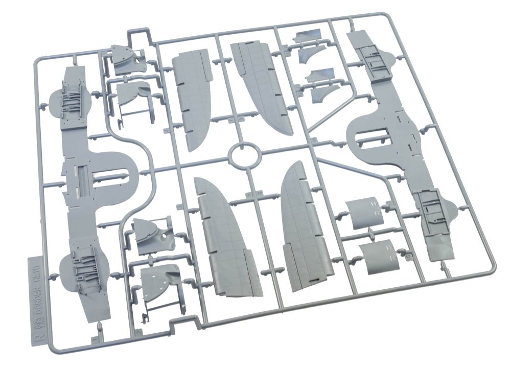
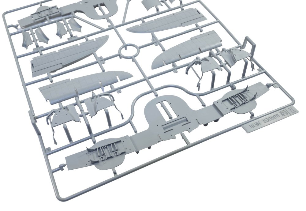
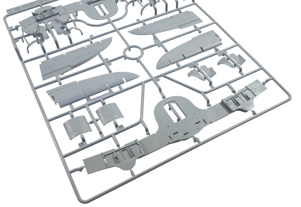
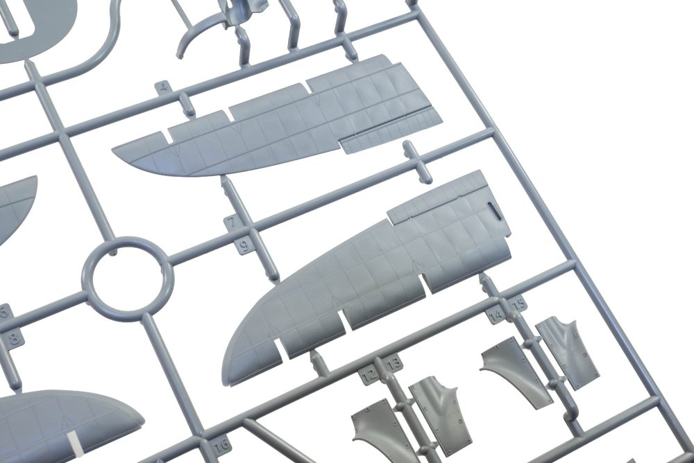
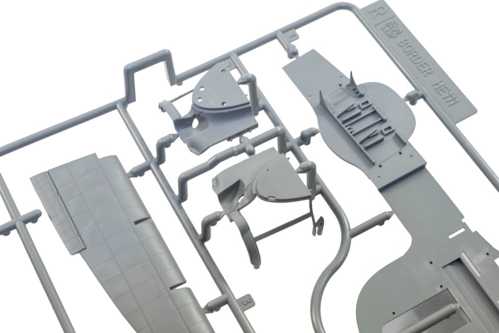
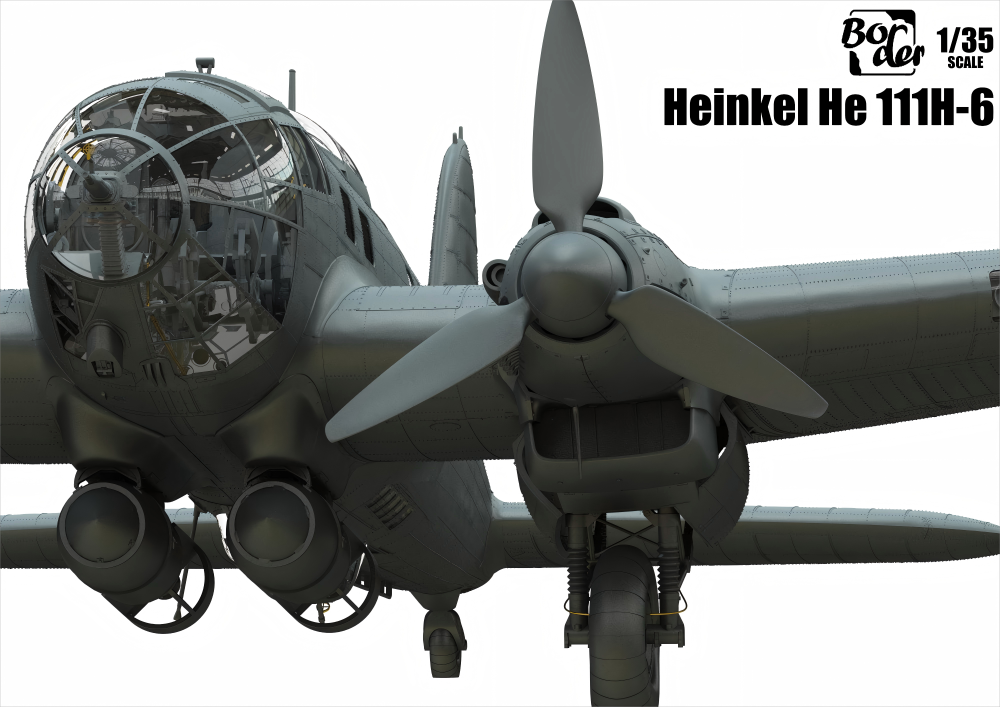
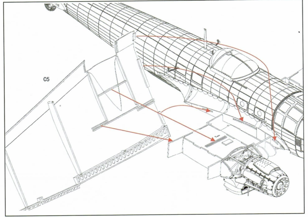
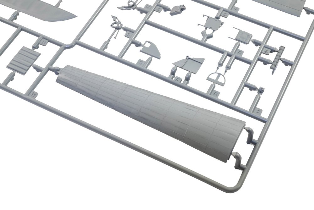
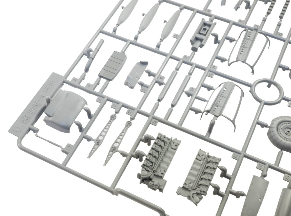
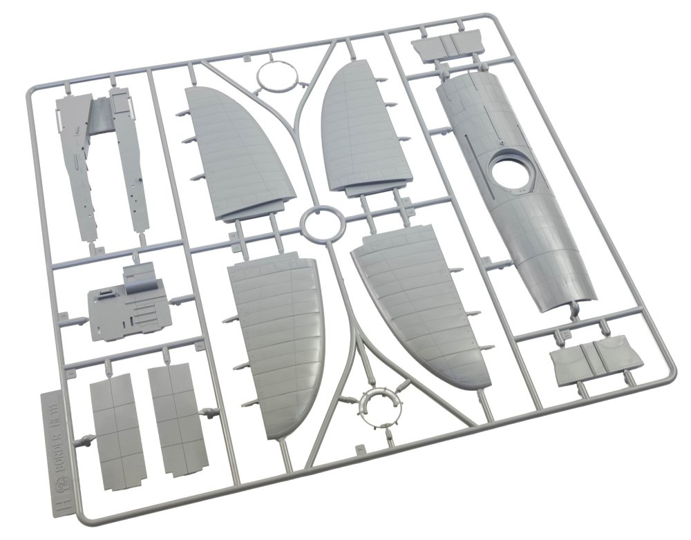
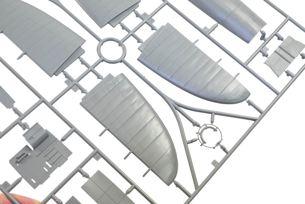
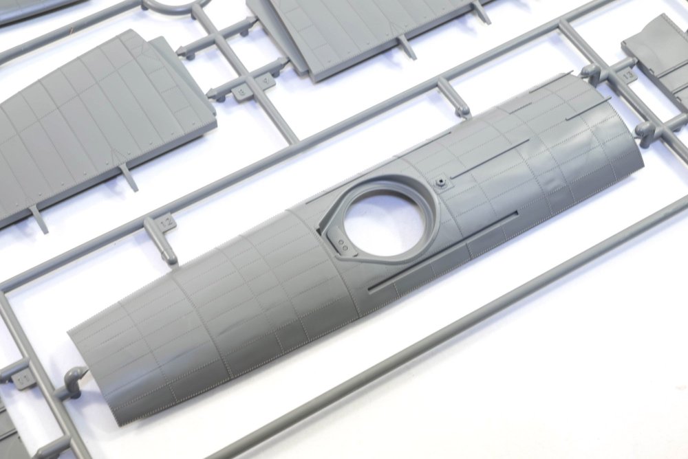
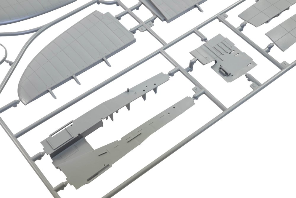
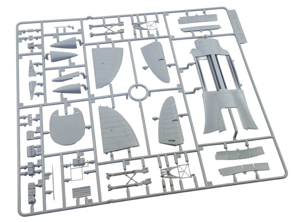
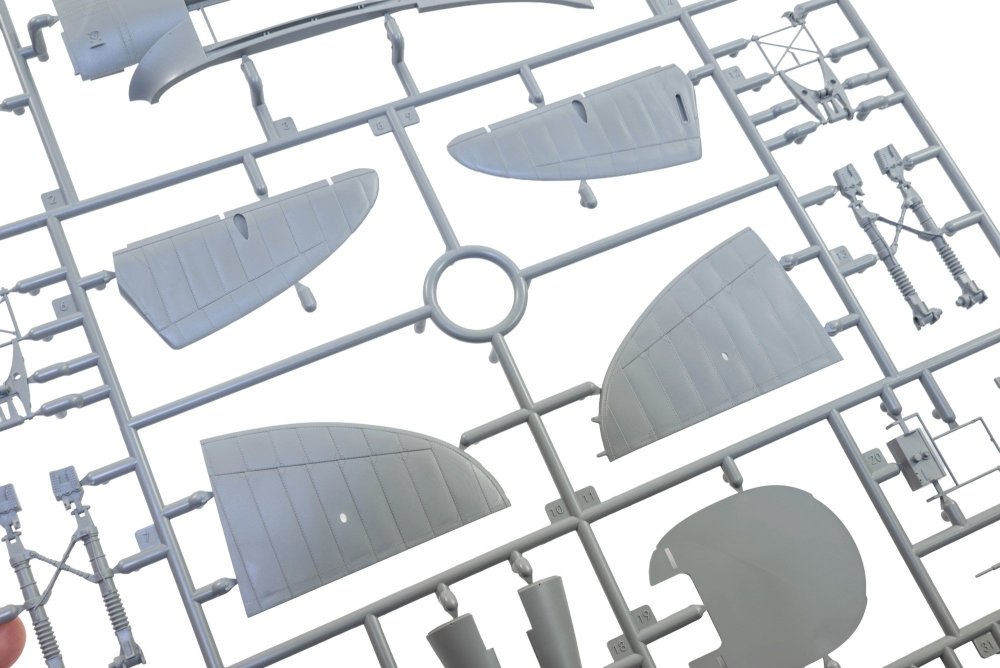
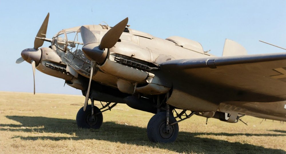
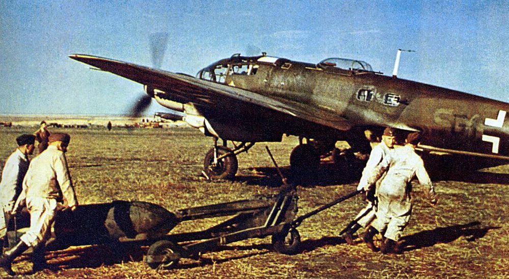
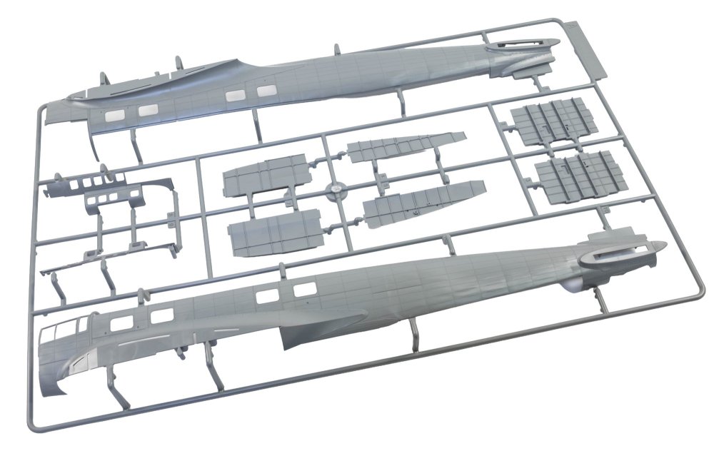
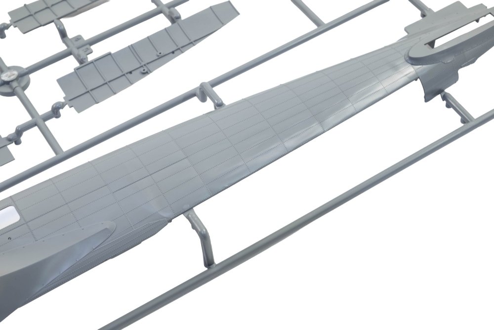
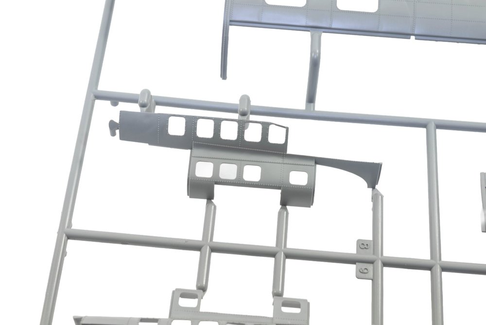
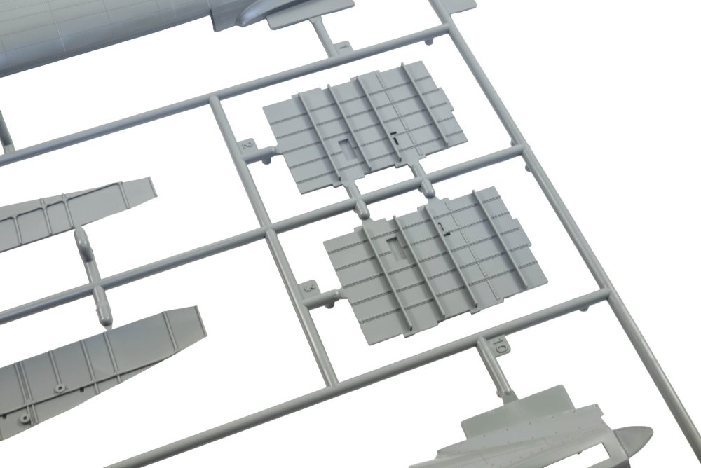
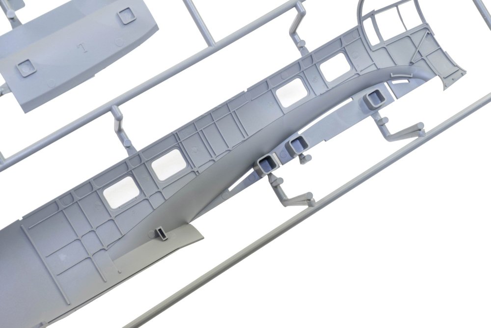
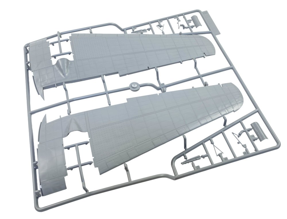
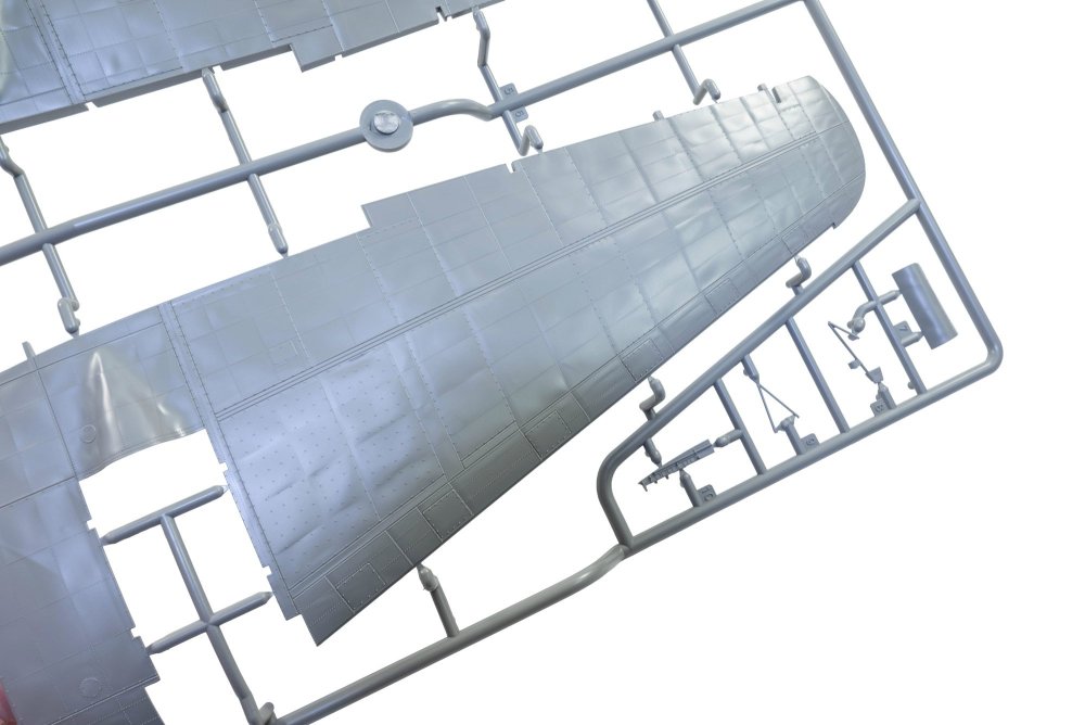
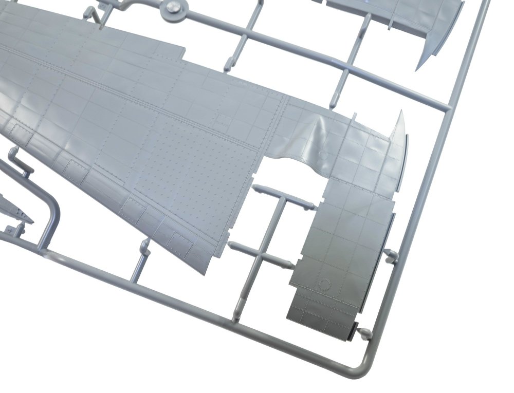
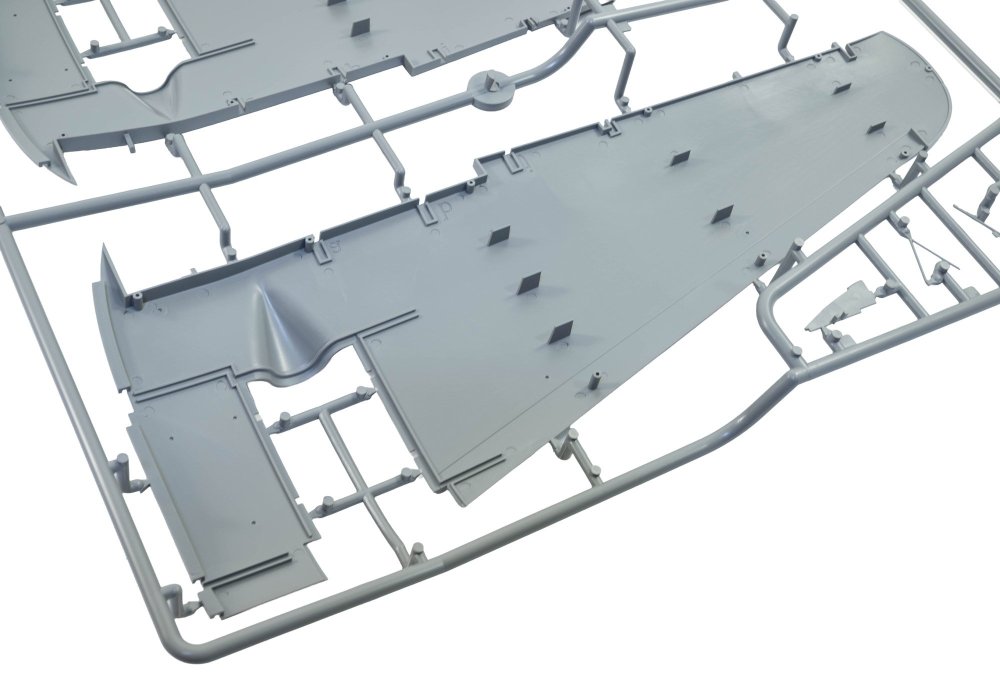
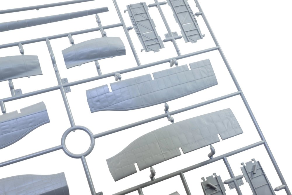
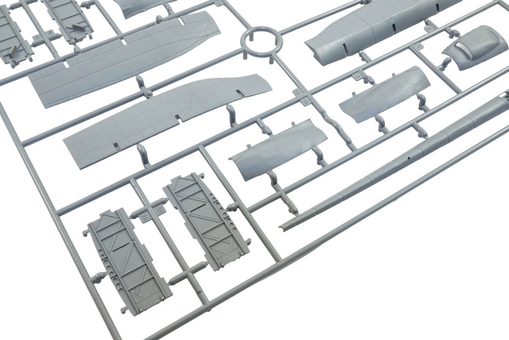
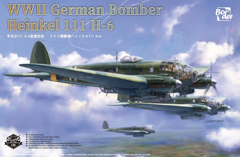
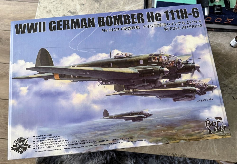
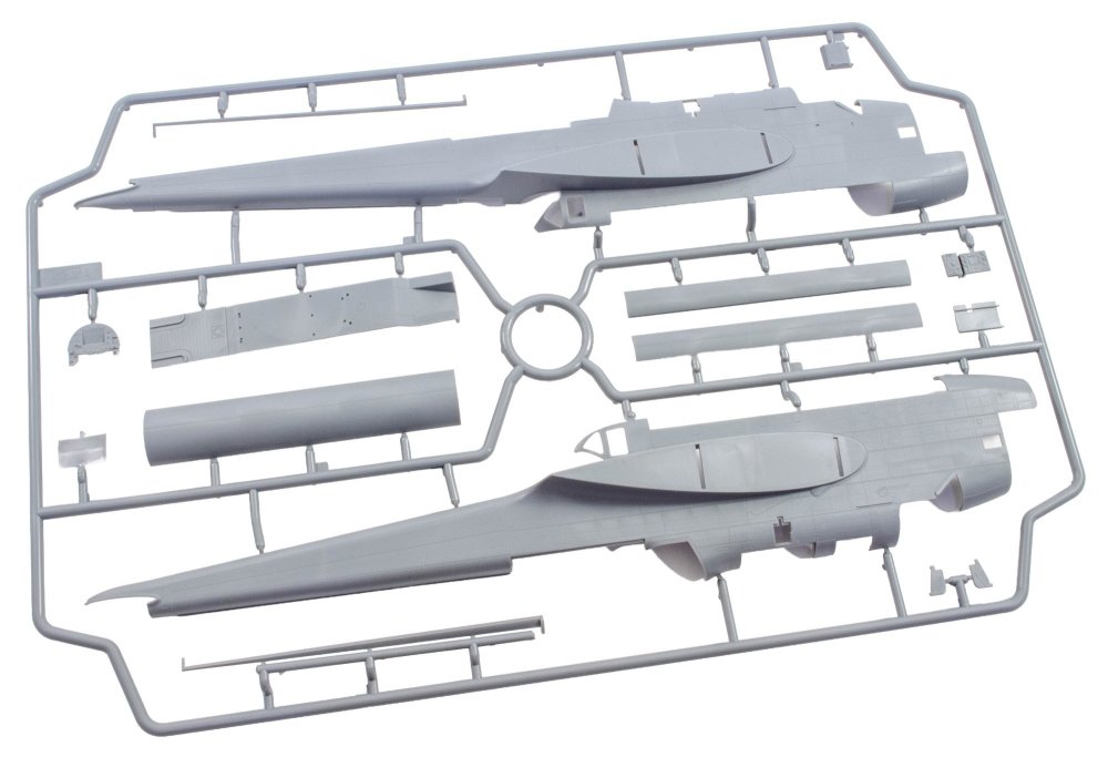
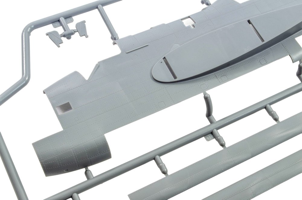
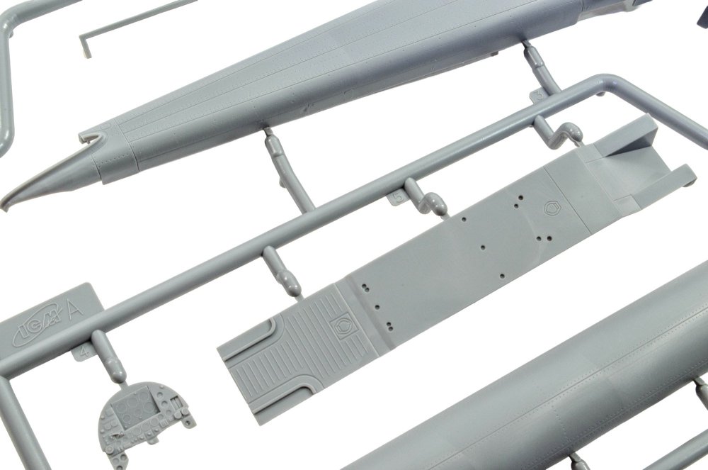
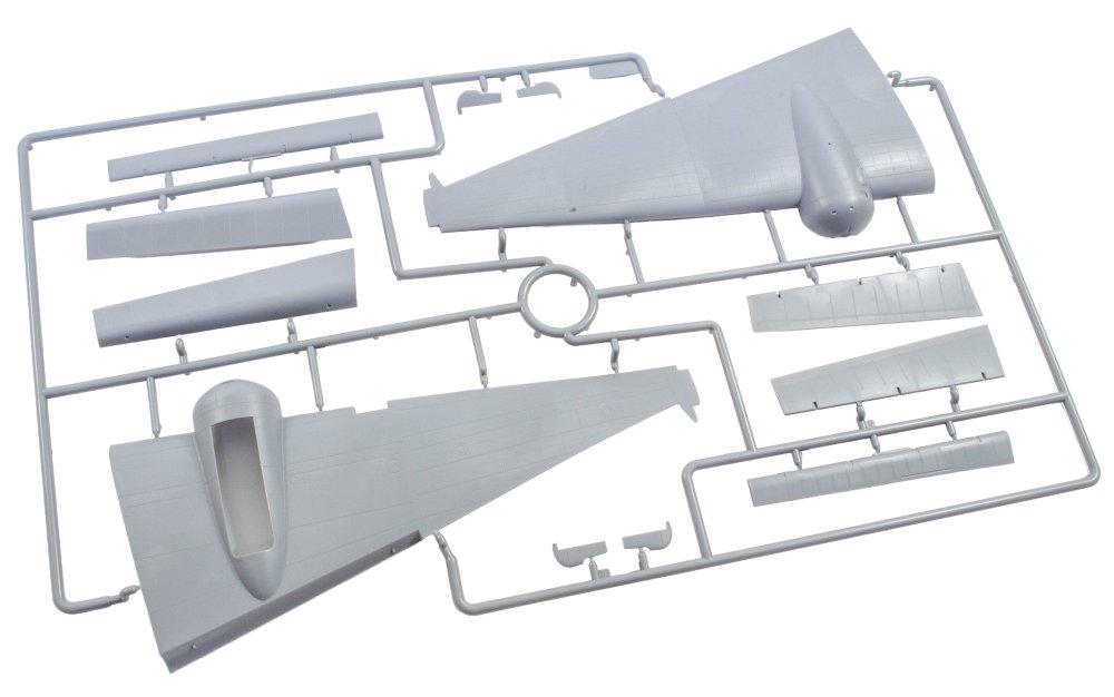
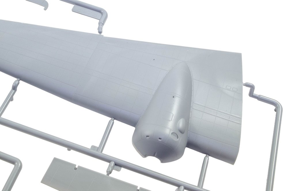
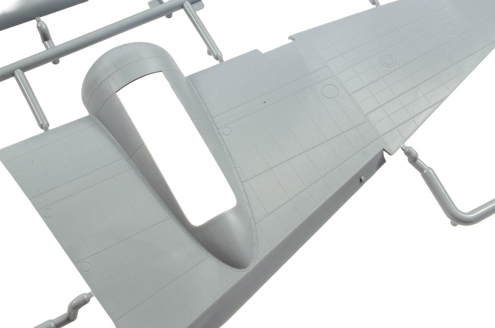
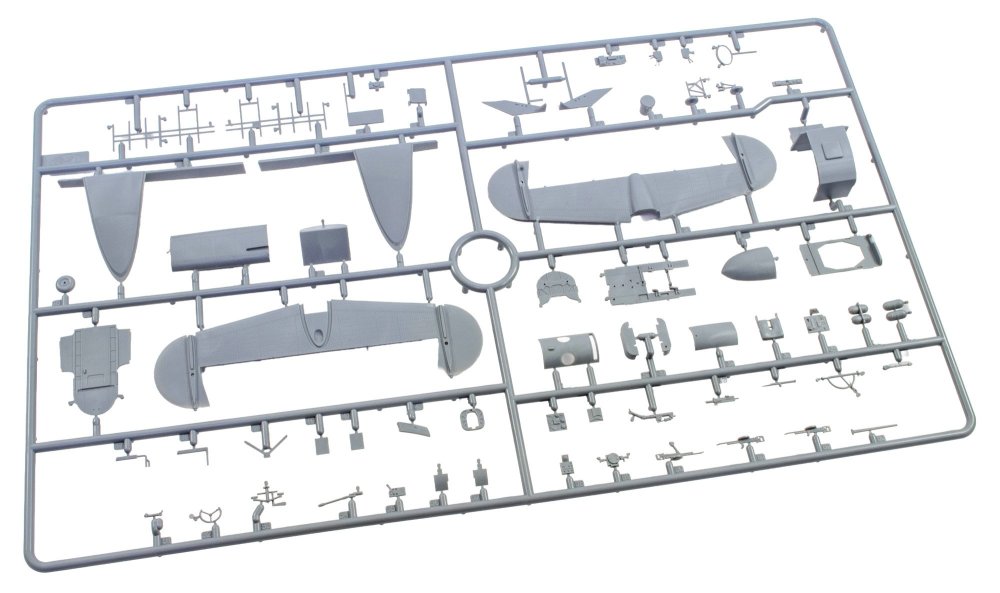
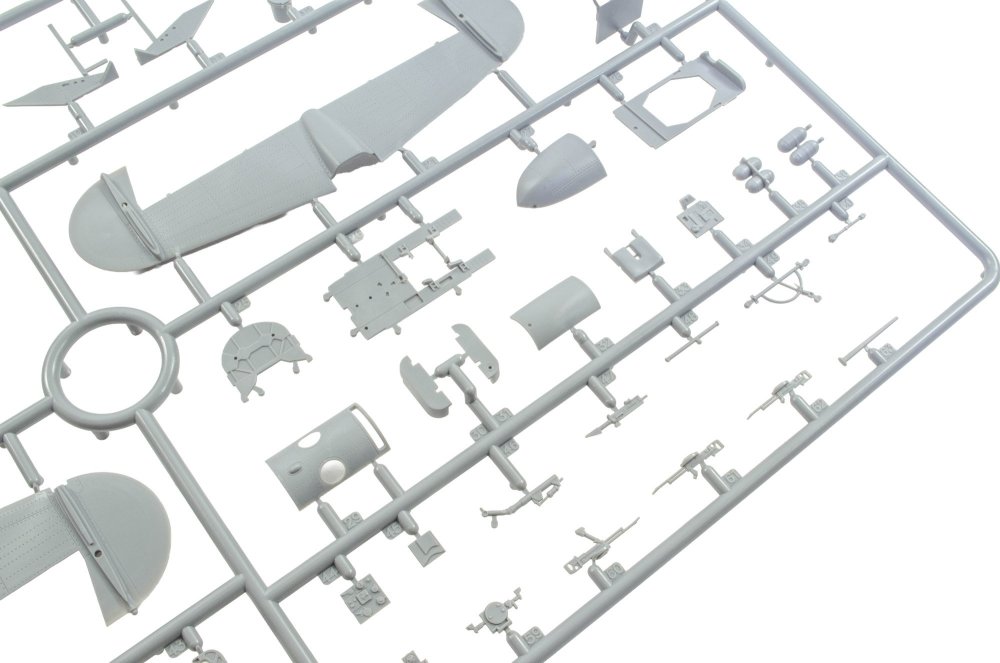
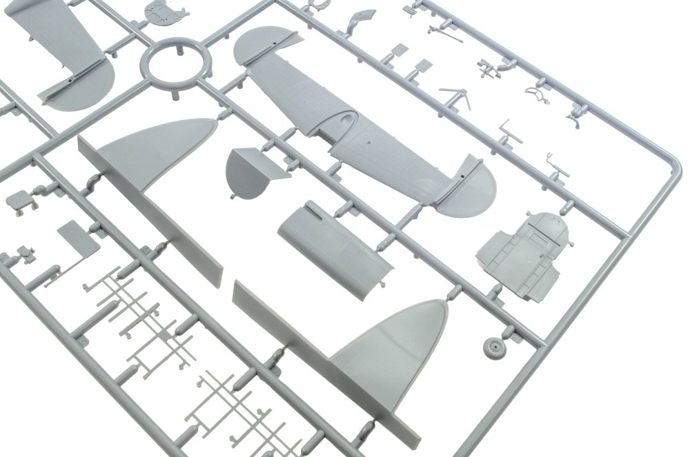
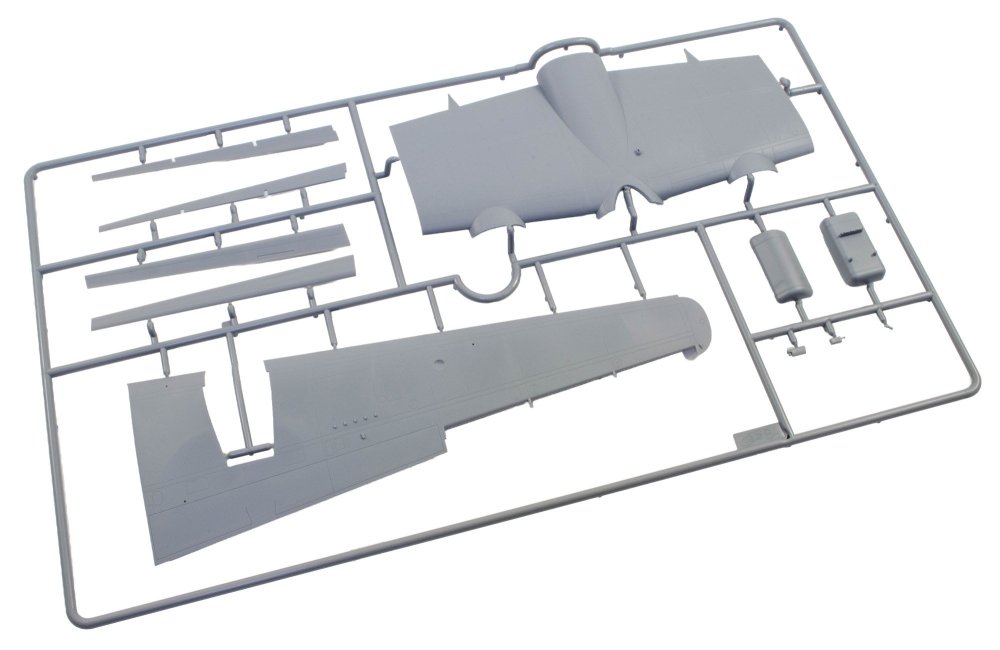
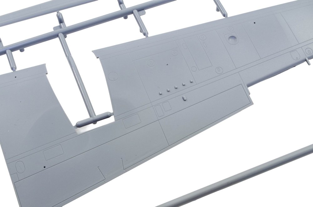
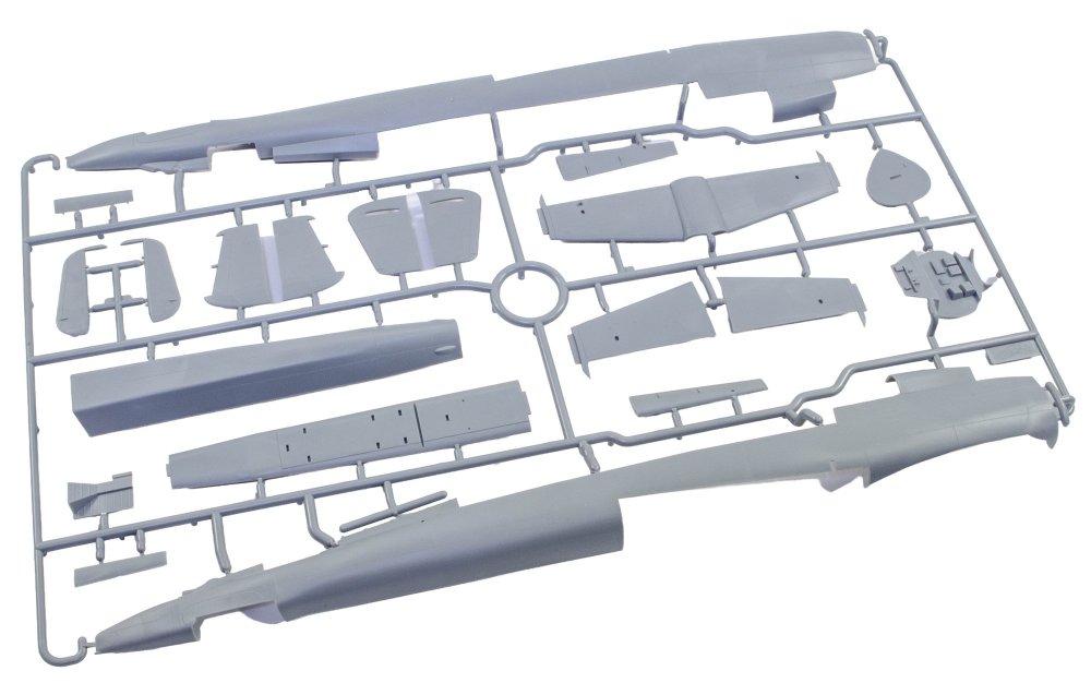
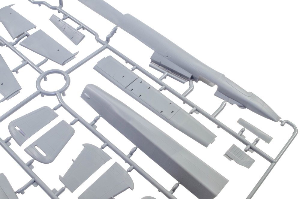
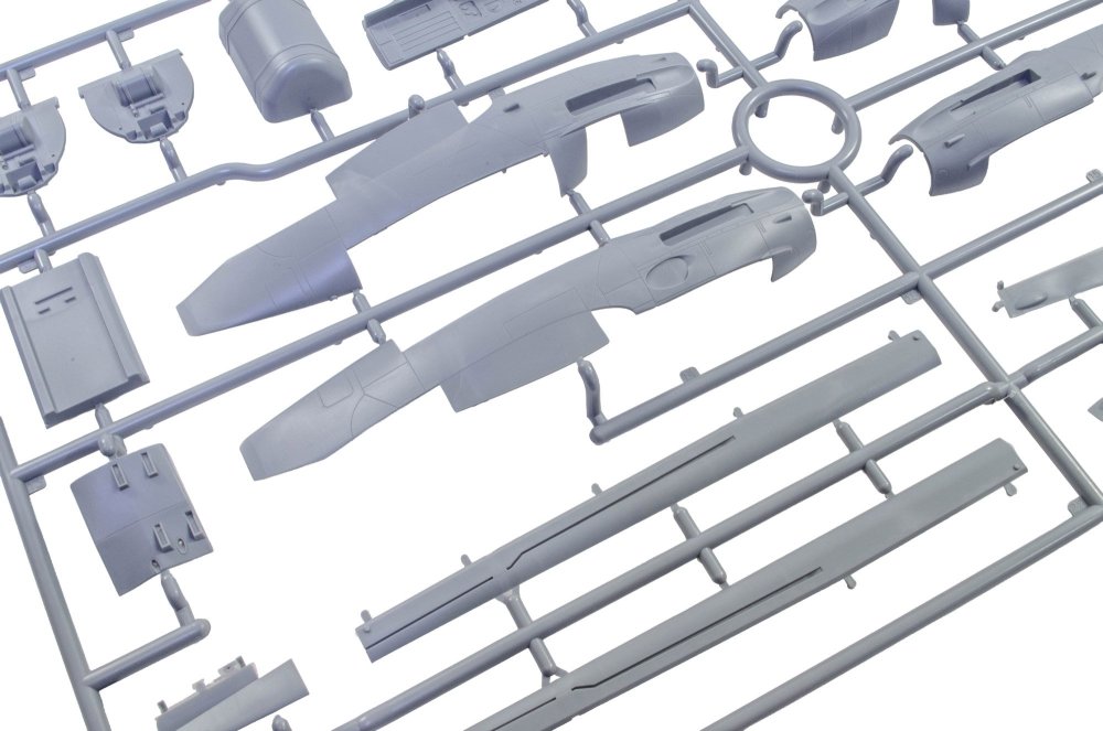
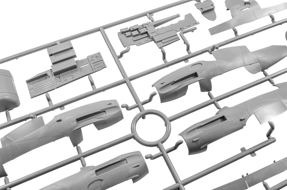
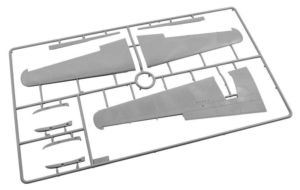
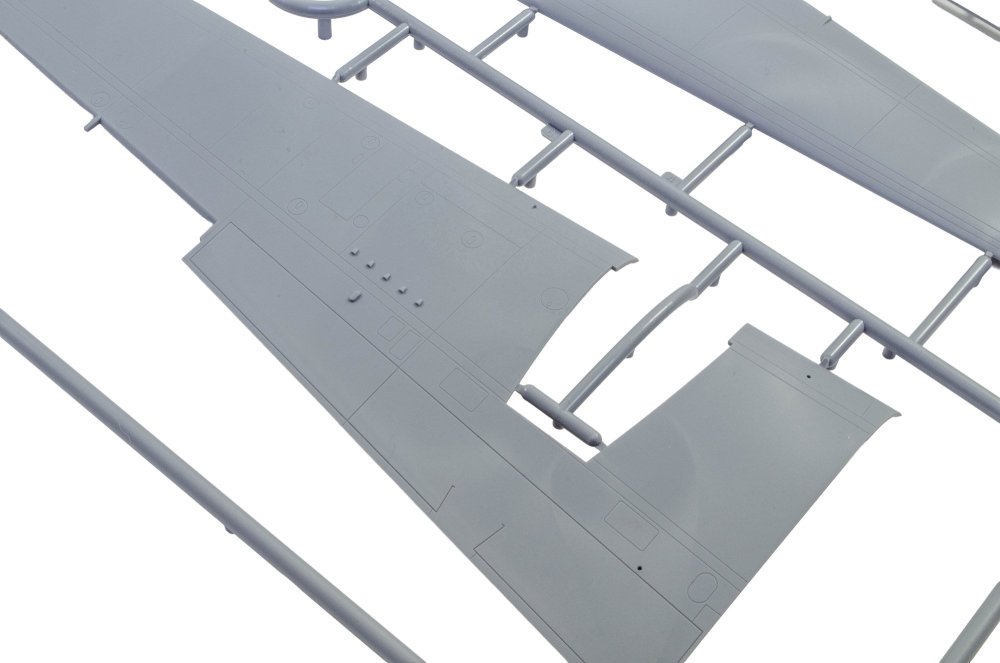
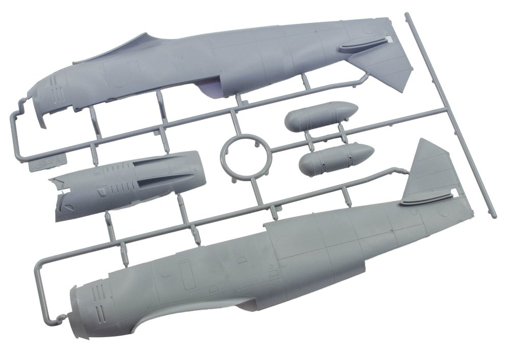
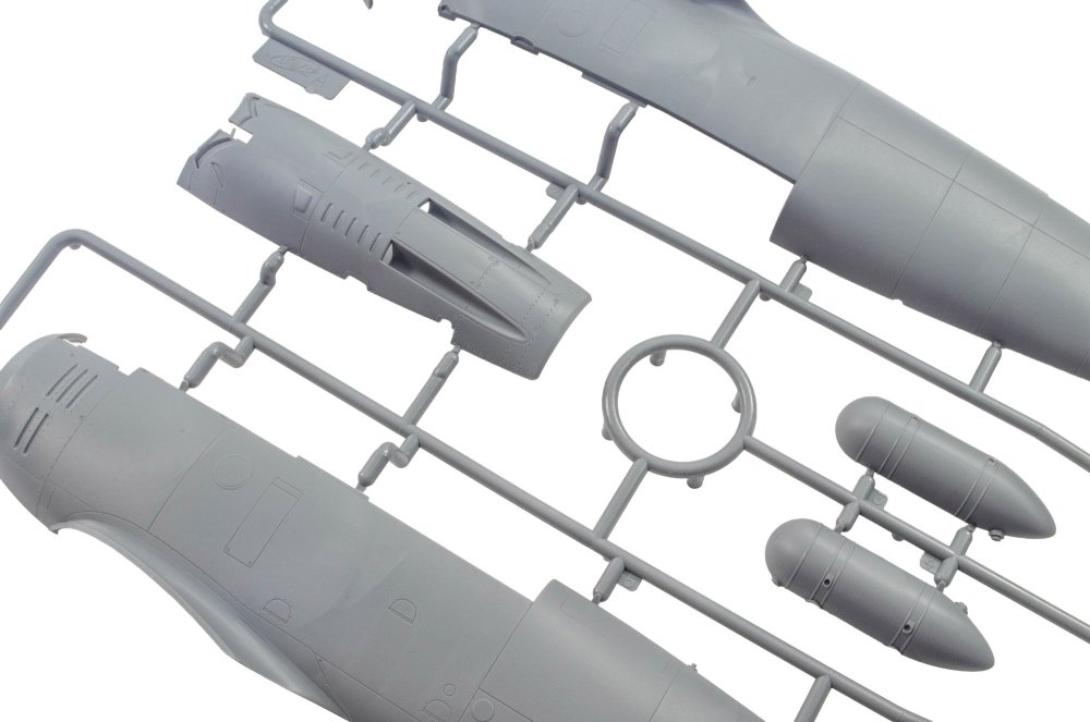
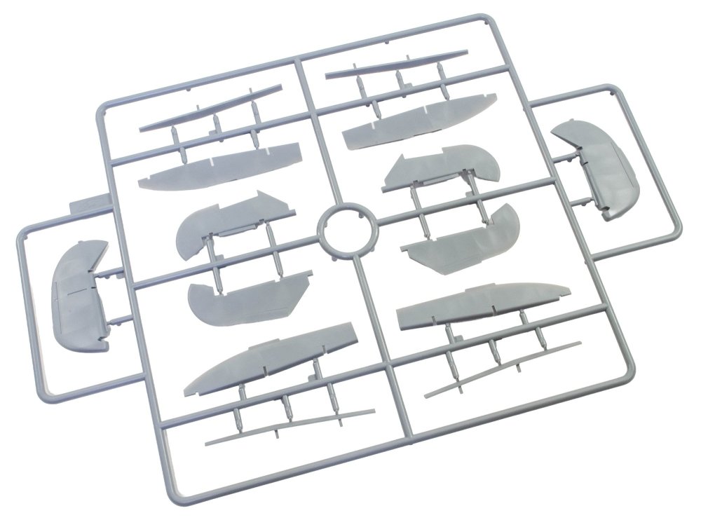
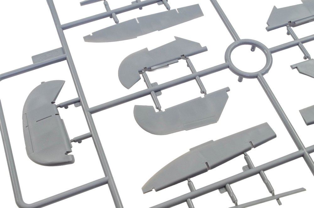
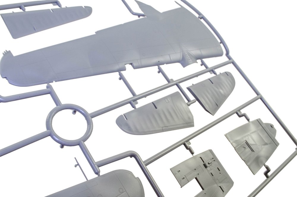
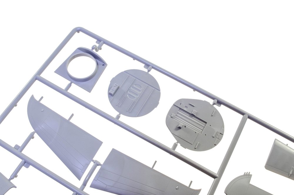
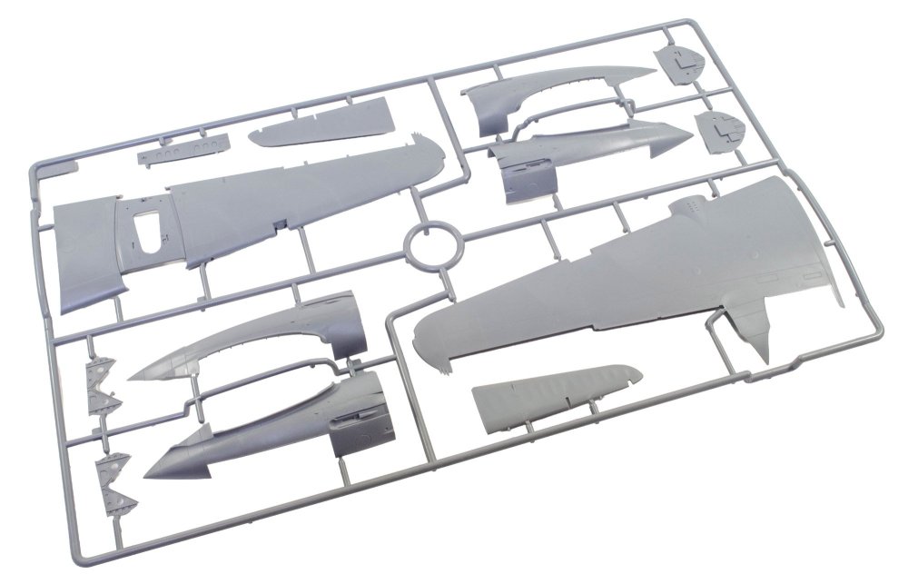
1:35 Heinkel He 111H-6 Border Model Catalogue # BL-018 Available for around £150 The Heinkel He 111H-6 was one of the most widely used versions of the famous German medium bomber developed by the Heinkel during the early years of World War II. The He 111 itself was originally designed in the mid-1930s by the brothers Siegfried Günter and Walter Günter, initially disguised as a civilian transport aircraft to bypass restrictions imposed after World War I. By the start of the war in 1939, the bomber had become one of the primary aircraft of the Luftwaffe, serving extensively in early campaigns and gaining recognition for its distinctive glazed nose. The H-6 variant appeared in 1941 as an improved model designed to increase performance and payload flexibility. It was powered by two Junkers Jumo 211F-1 engines, which provided greater reliability and allowed the aircraft to carry heavier ordnance. One of the defining features of the H-6 was its ability to carry torpedoes, enabling it to operate as a maritime strike aircraft. Because of this capability, the aircraft was frequently used against Allied shipping in areas such as the North Sea and the Arctic Ocean, where German forces attempted to disrupt supply routes. During the middle years of the war, the He 111H-6 served in multiple roles including level bomber, torpedo bomber, and sometimes as a transport aircraft. It participated in operations on the Eastern Front and during the Battle of the Atlantic, often flying long missions over hostile territory. However, as Allied fighters and air defenses improved, the He 111 design began to show its age, suffering heavy losses by 1943. Despite this, the aircraft remained in service for much of the war due to Germany’s limited ability to replace it with newer bomber designs. The kit This is my first experience with a Border Model kit, and this release may or may not be indicative of how the previous releases faired, so forgive me for basing this solely on how I see this new kit. The He 111H-6 comes in a large and deep box with a very rigid lid which gives a lot of protection for the many sprues within. Some of the more fragile sprues are stored within boxes of their own, printed with images of contents. One such box contains the three clear sprues. In total, there are around eighteen sprues of mid grey styrene. For some reason, two of these aren't shown on the parts map, despite being used. There are also three clear sprues, one fret of photo-etch metal, two decal sheets, and one large instruction manual. SPRUE A This sprue is the first thing you see when opening the box lid, as it sits on a boxed sprue immediately below it. You can straight away get an idea of the size of this subject in 1:35, albeit minus the tail cone and forward cockpit glazing. The main parts here are obviously the fuselage halves. I've played about with the lighting for a number of my photos, so you can see that oil canning that is one of the main features of this release. Addressing an elephant in the room here, you'll also see the raised riveting. Looking at plenty of images of the He 111, both historical and museum, the riveting is somewhat of an anomaly, but then again, so are the rows of divots we also see, albeit less of an issue to the average modeller. Maybe Border are also aiming at armour builders, hence some of the agricultural aspects of surface detail! Anyway, this is no deal breaker for me. The breakdown of the fuselage is clear to see, with joints along panel lines, removing the need to start sanding, filling and adding more rivets. I quite like this aspect, also seen on the big scale Airfix birds, and most recently on Kotare kits. The upper section of the fuselage is a separate part, as is the belly and lower gondola too. Internally, the fuselage contains stringer and ribbing detail. Other parts on this sprue include the gondola itself, and internal wing root insets which plug onto the main internal framework. SPRUES B & C Apart from a few smaller parts, these sprues are for the wings. Again, I've tried to show you the surface textures in my photos. I do quite like that canning. Not sure how many 111s ever survived long enough to stress like that, but hey! Also note how the wing leading edges are separate parts, so no seams to eradicate. Spacers are moulded within the wings to separate the halves when glued together. This is instead of spars and any possible sinkage along internal construction elements. SPRUE D This sprue contains the inboard landing flaps (cumbersome as they are), wing leading edge strips, undercarriage doors and gear bay side walls, and oil cooler air intakes. The surface textures are quite obvious in these images. PART TWO in a short while...


-
Local courier just delivered this beastie today.
-
Lovely blades! Jeroen, hi.
-
Just got these from Hannants, ready for the 1:35 He 111 landing here. Ignore that code on sheet
-
I should be at Telford this year. Not made the trip for a long time now. Been 14yrs since I worked the Zoukei-mura stall. Time flies.
-
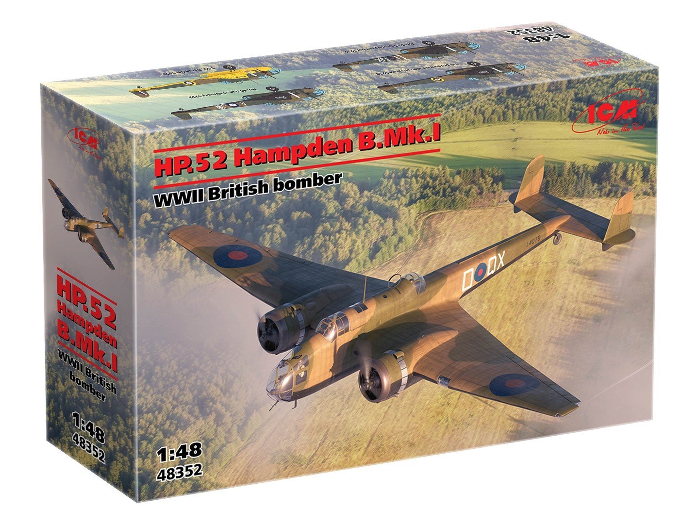
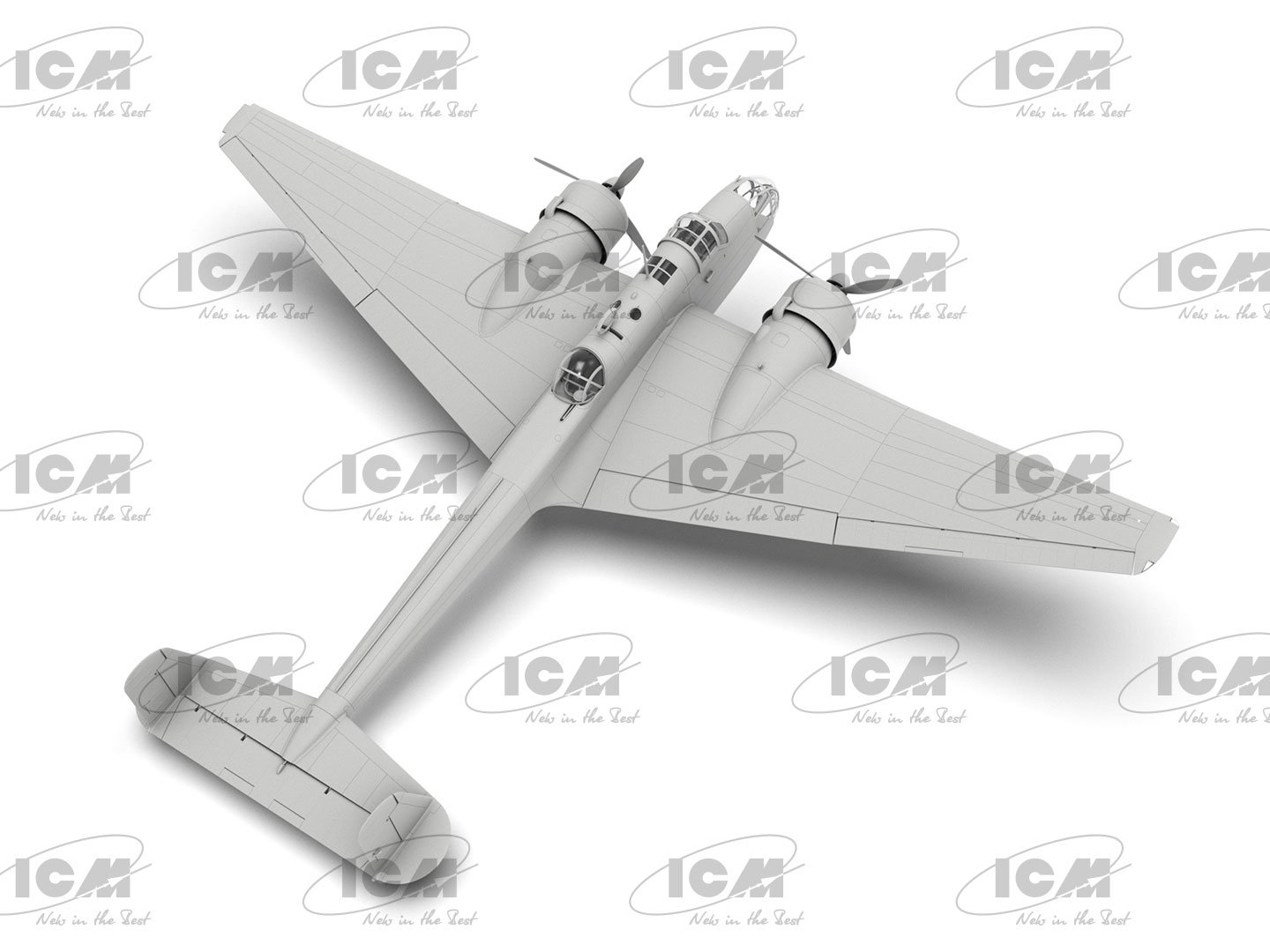
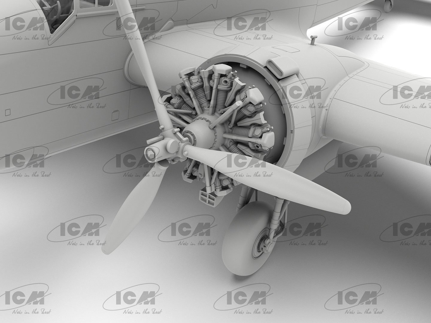
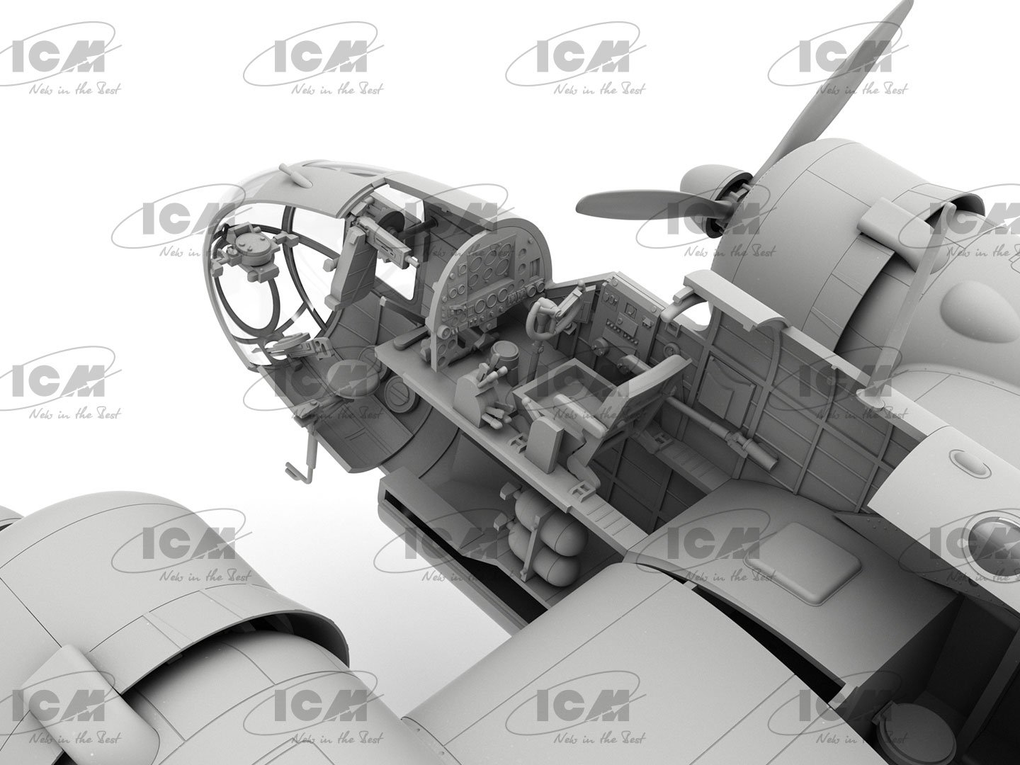
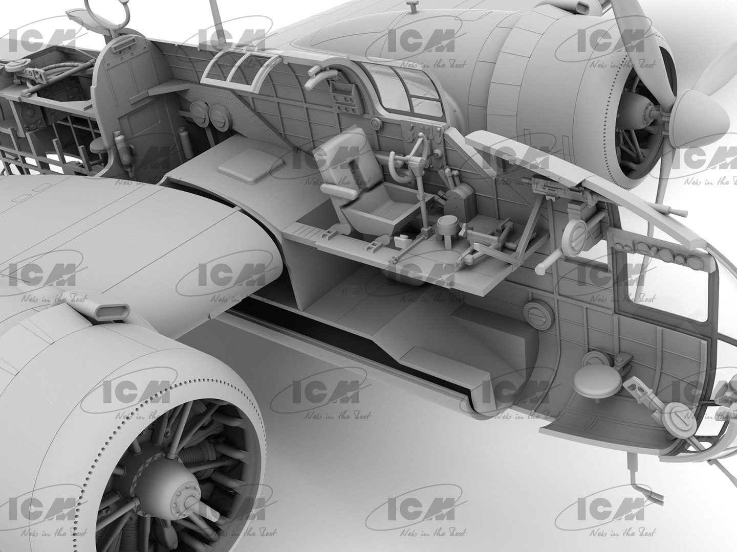
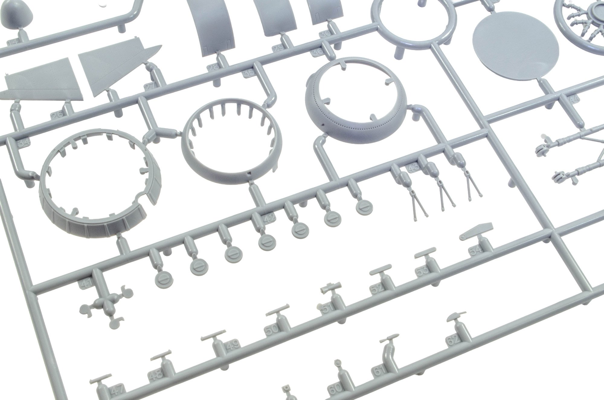
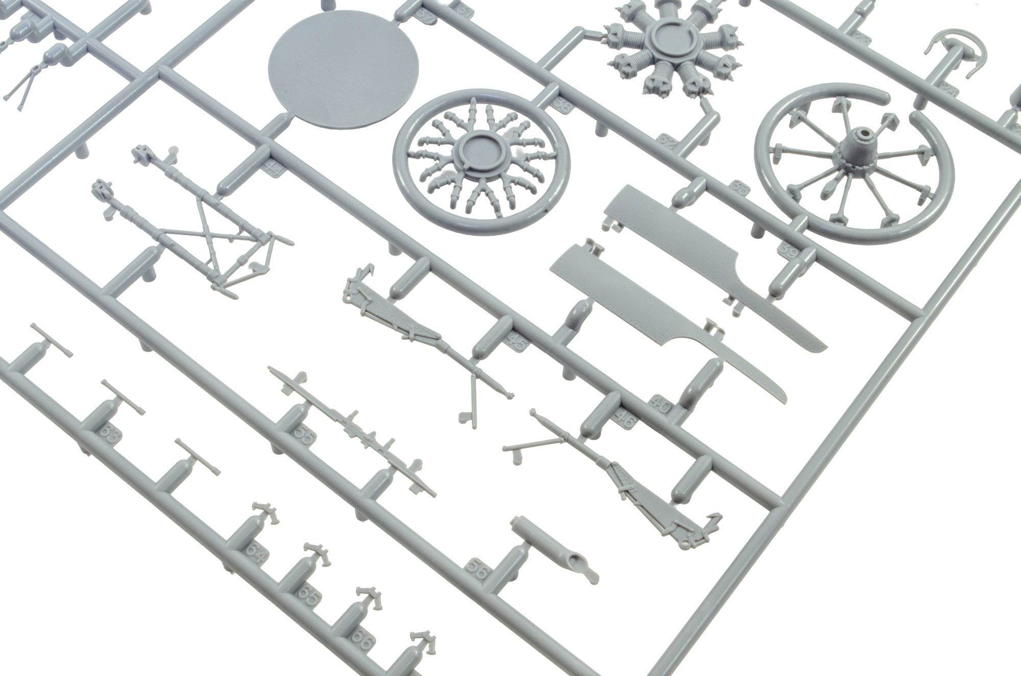
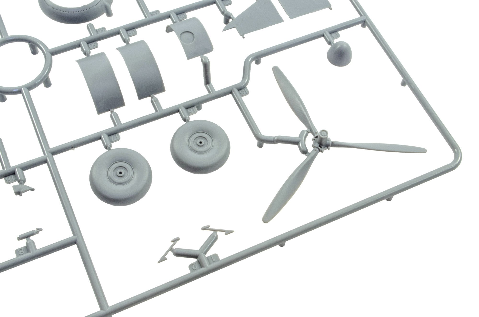
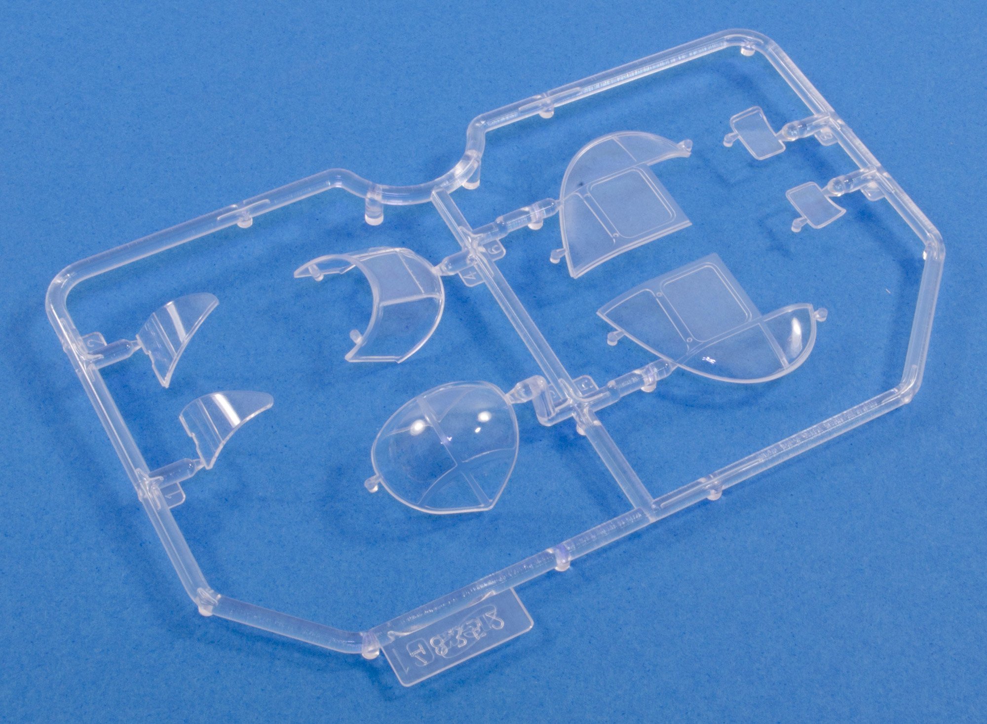
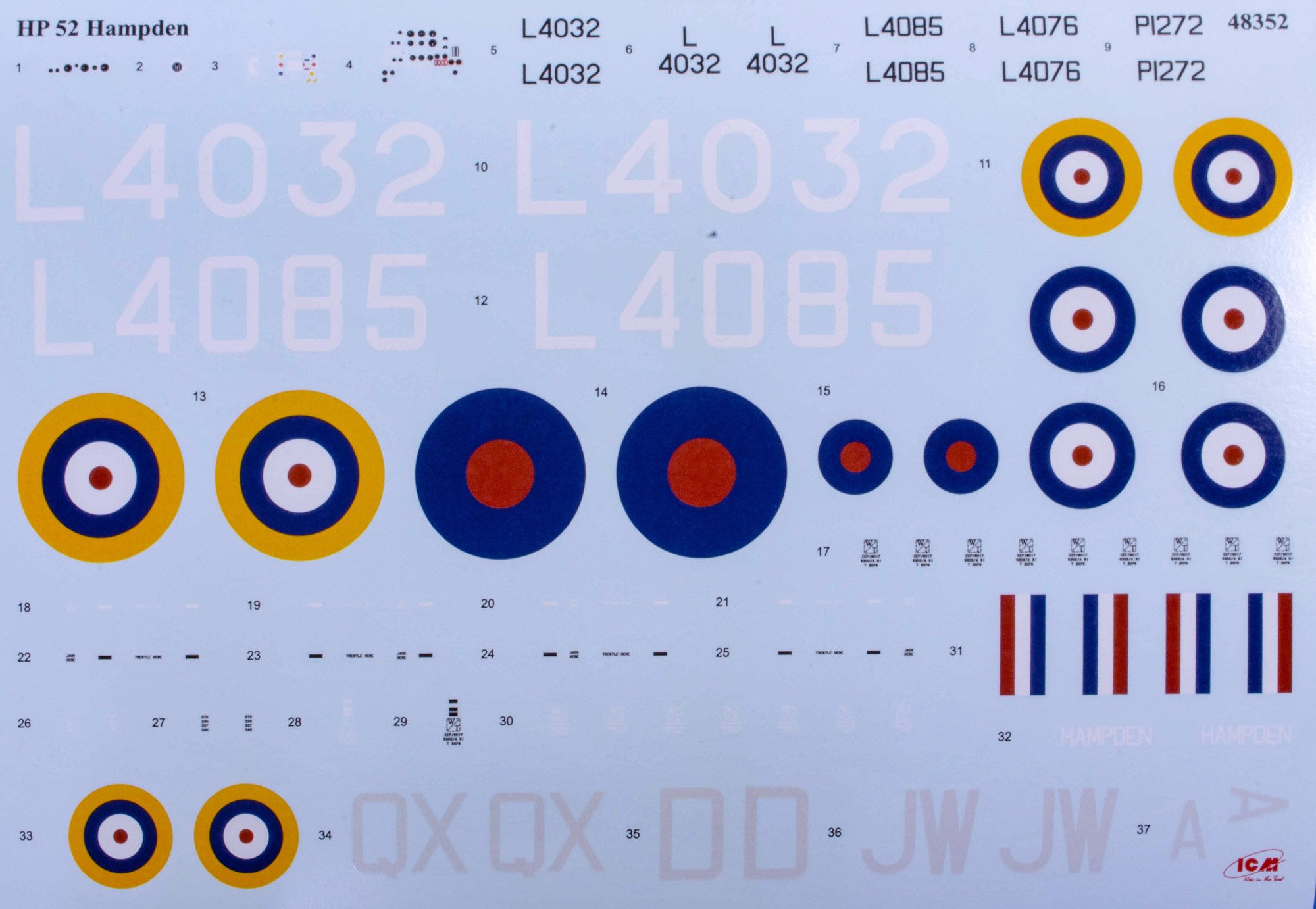
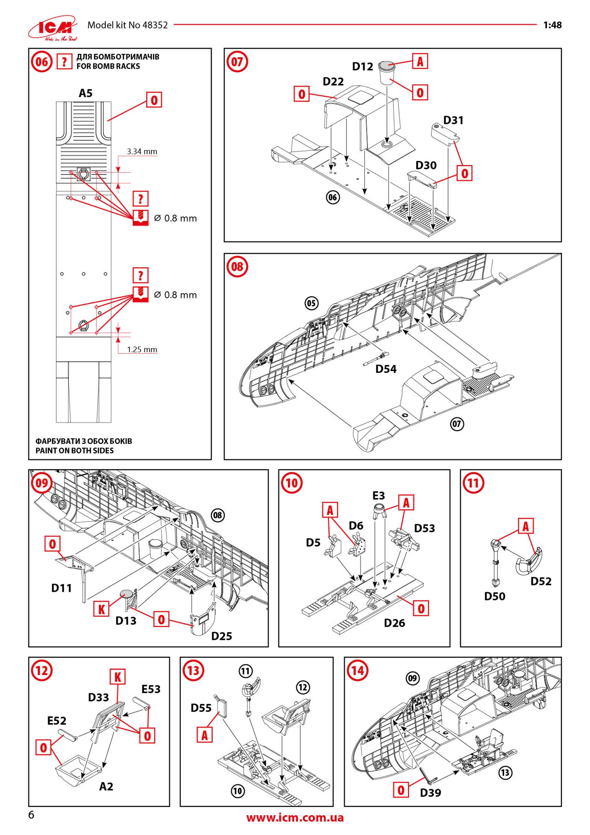
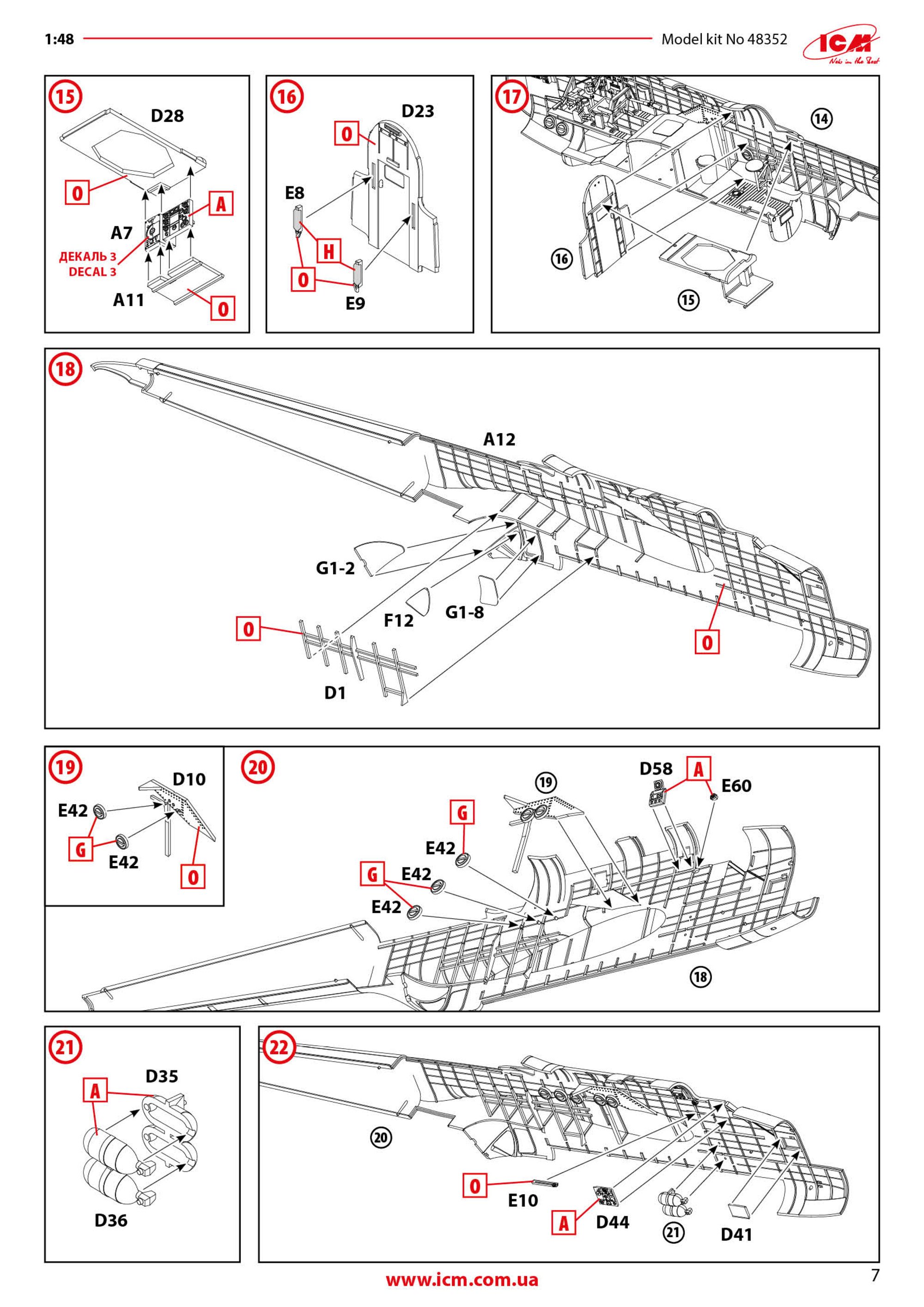
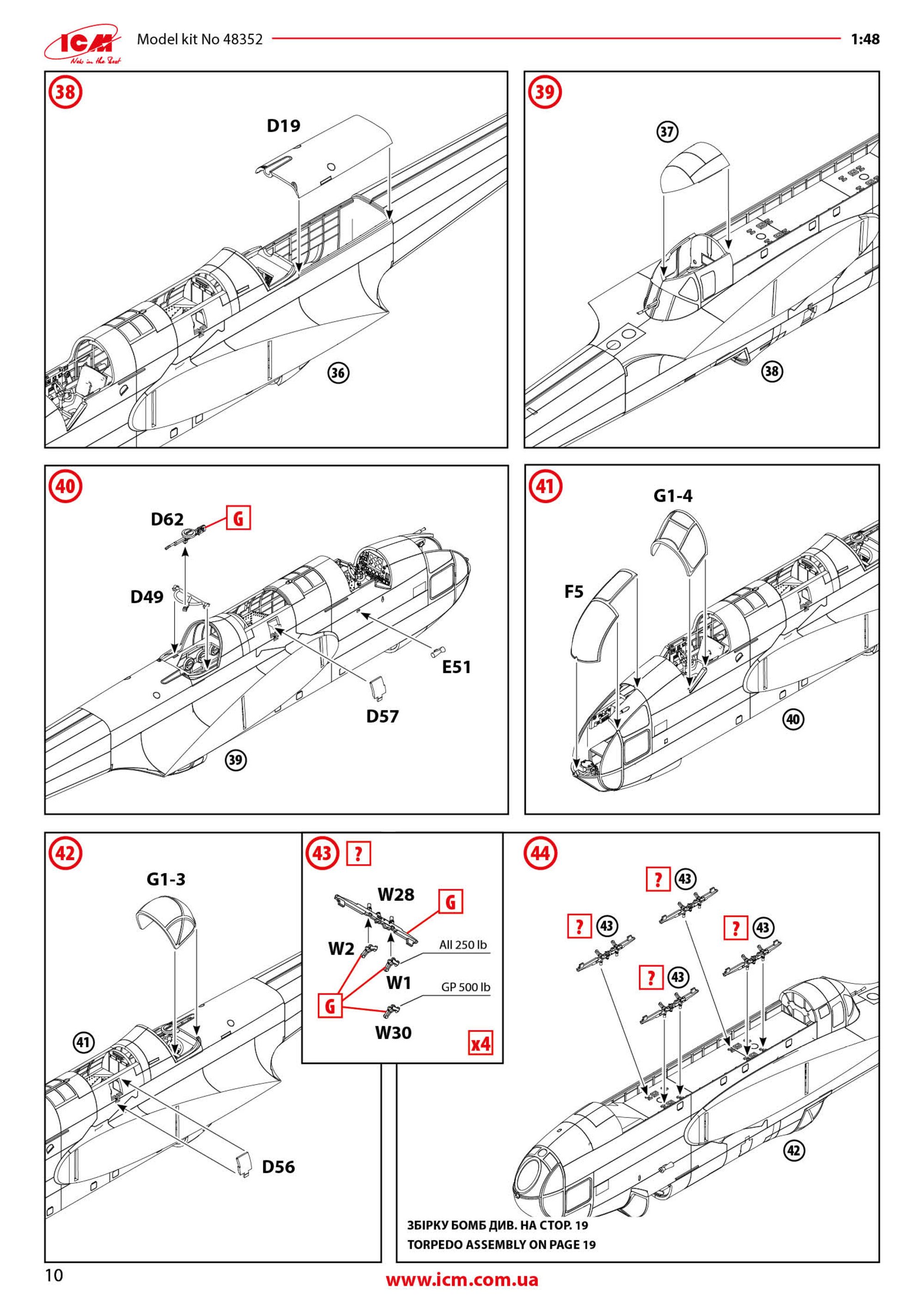
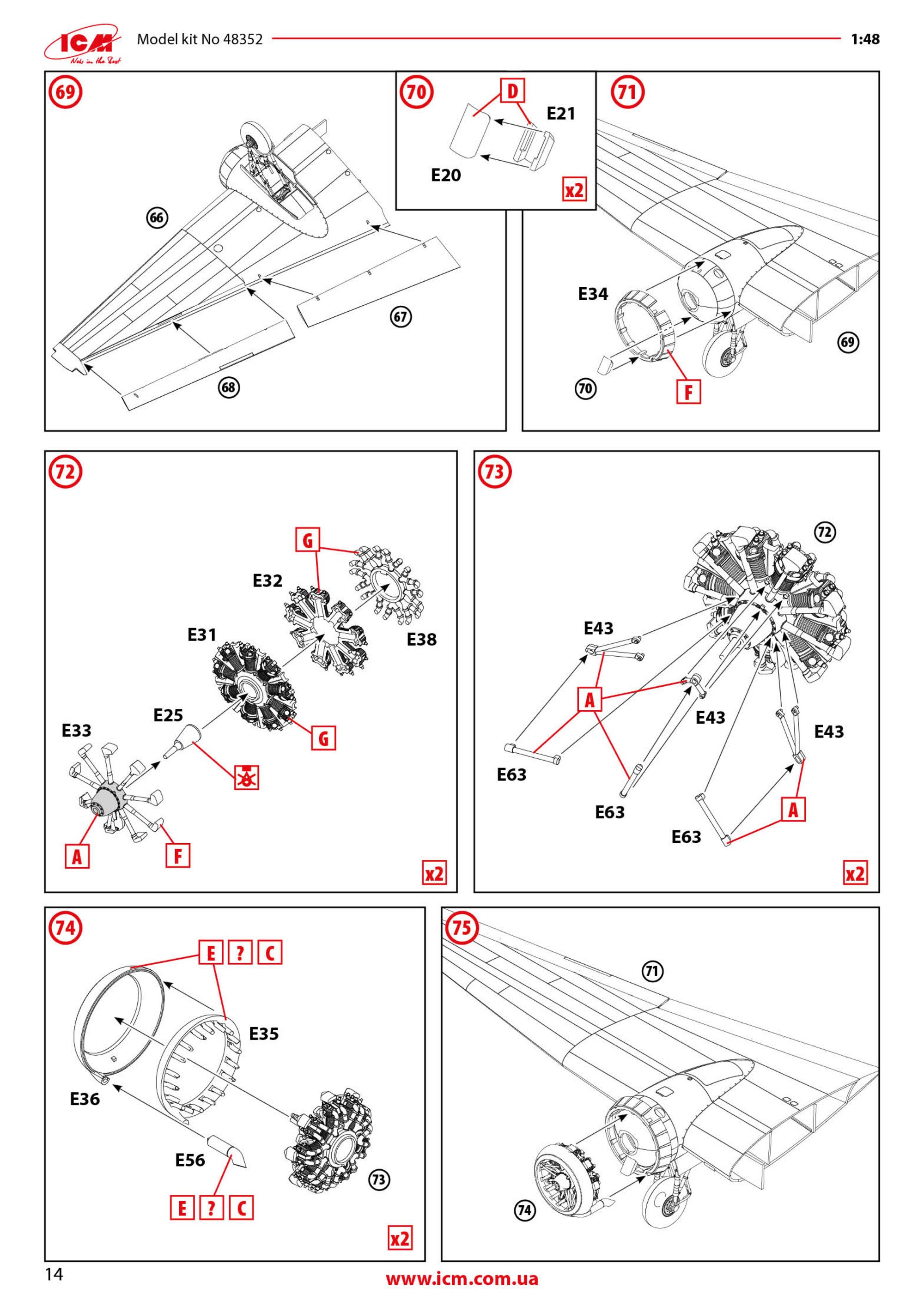
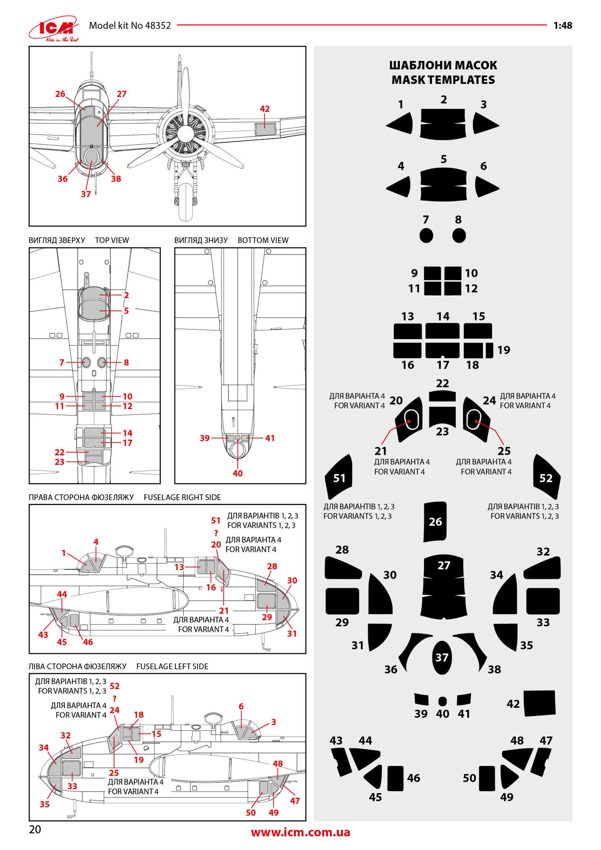
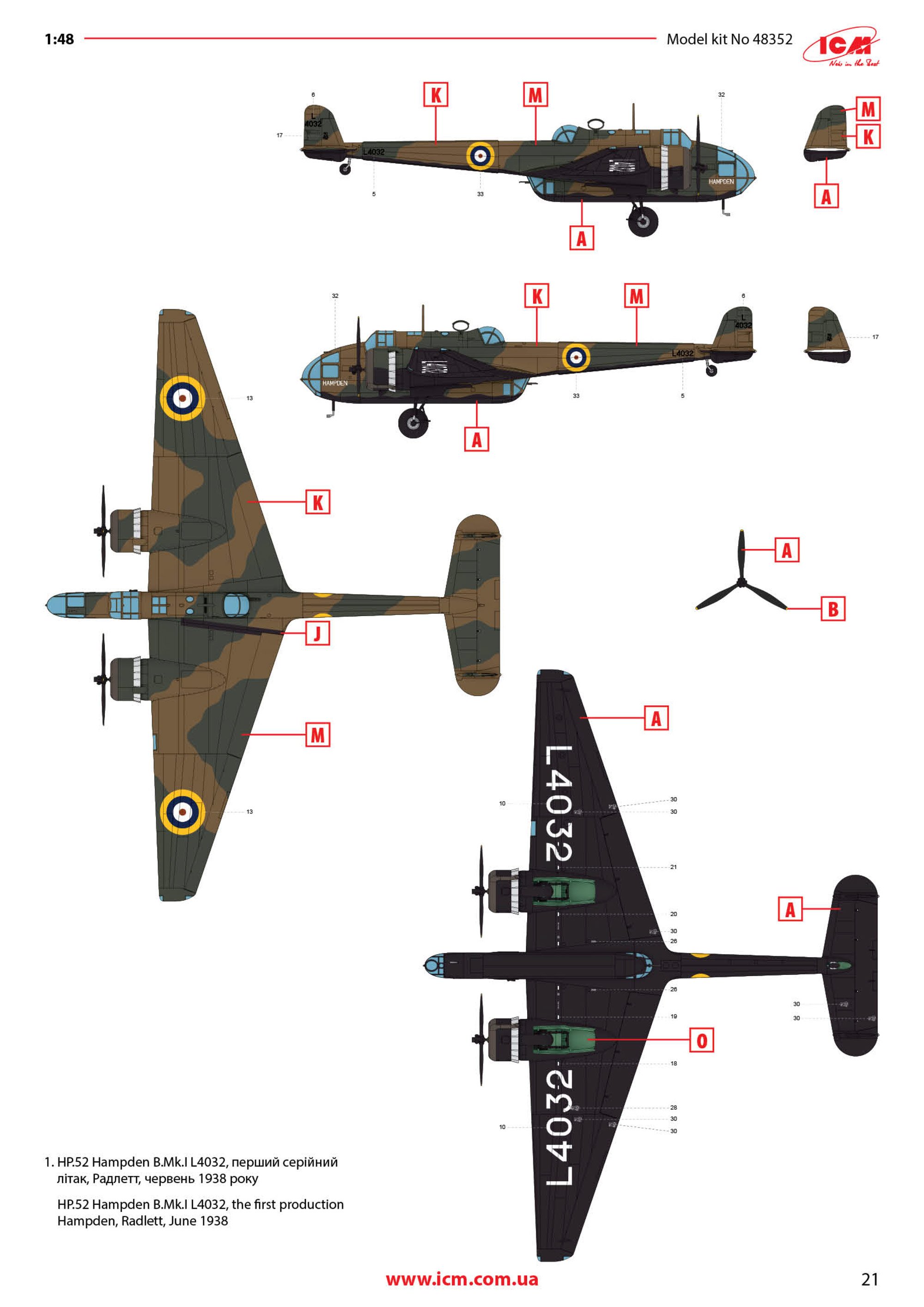
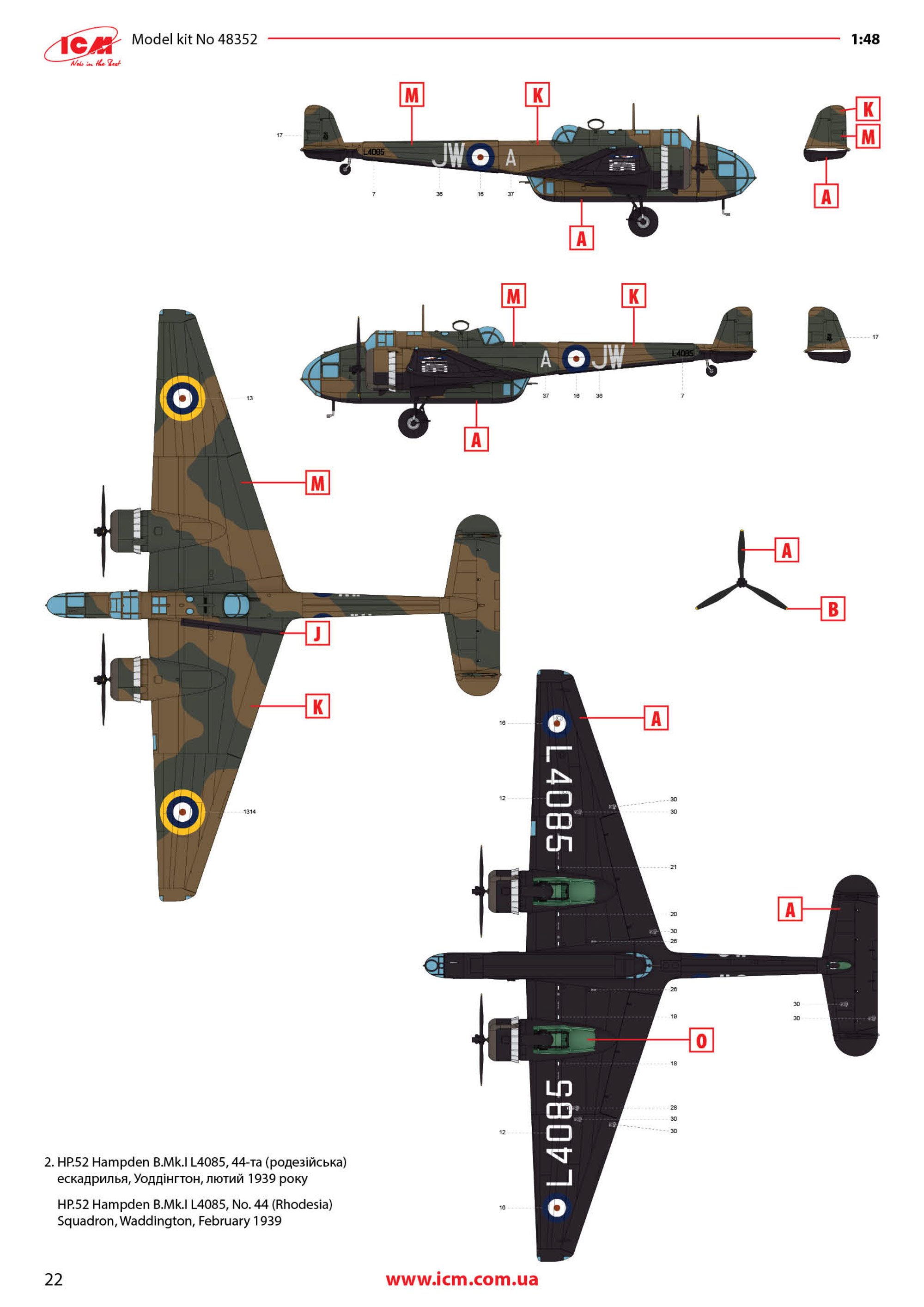
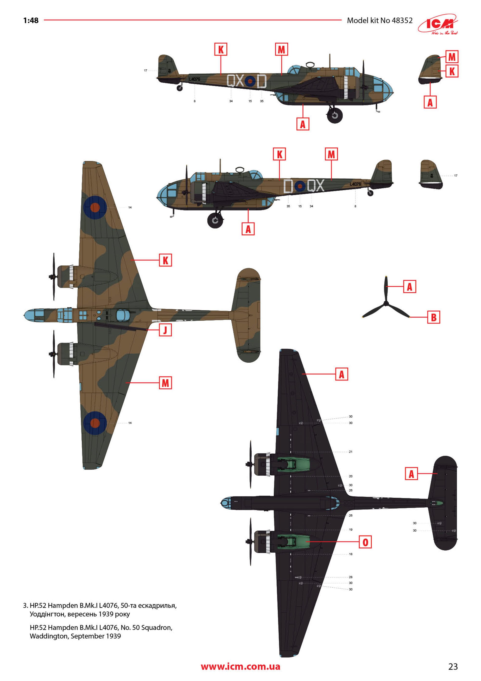
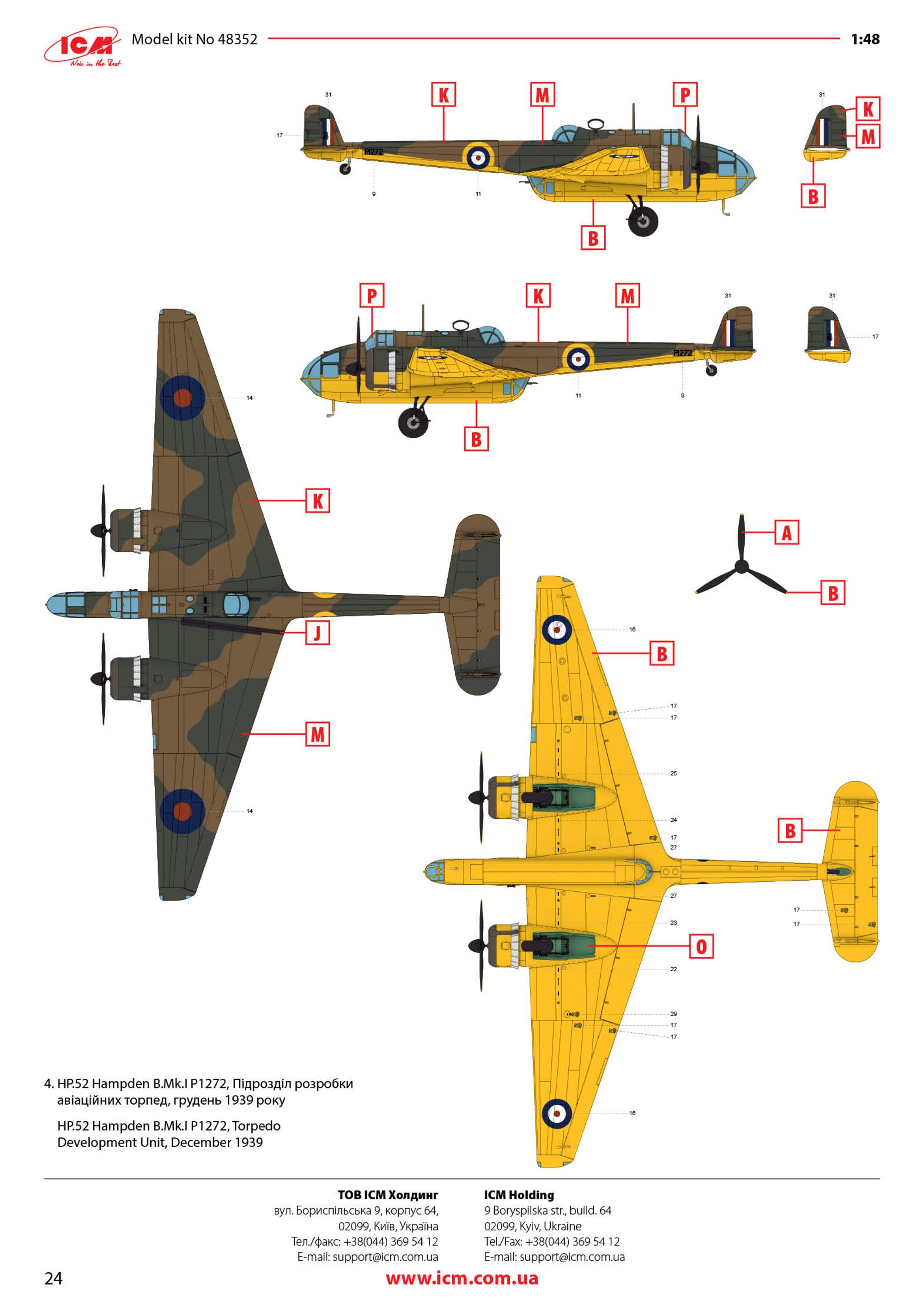
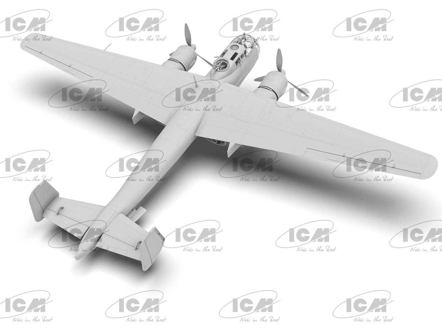
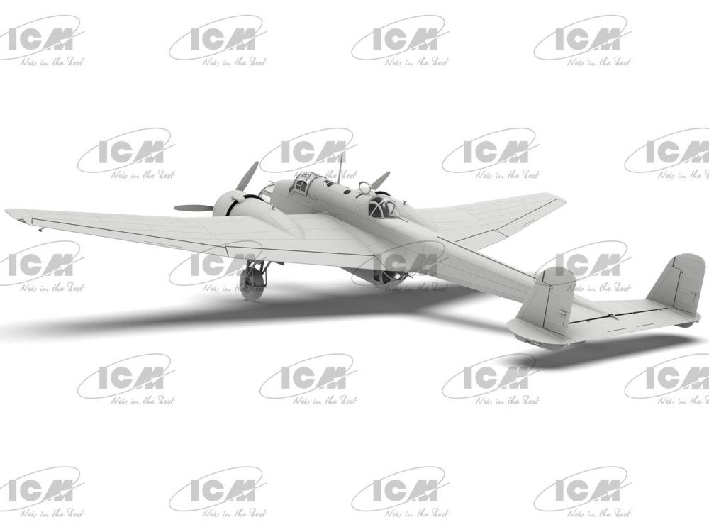
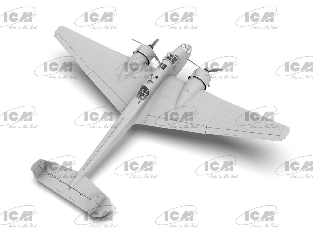
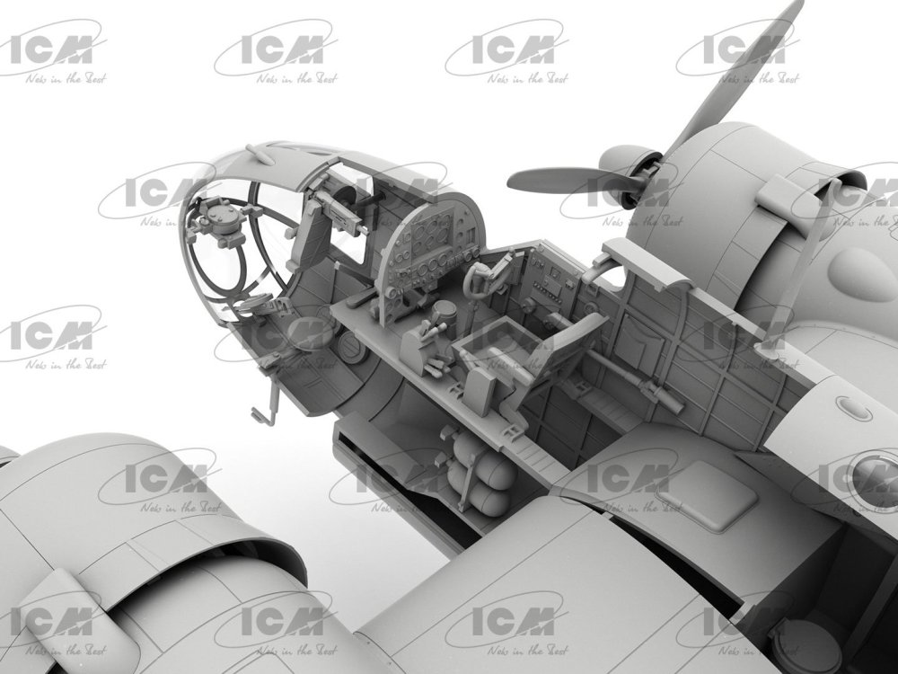
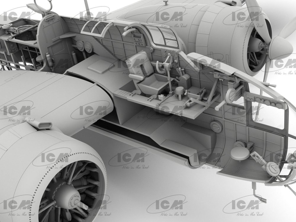
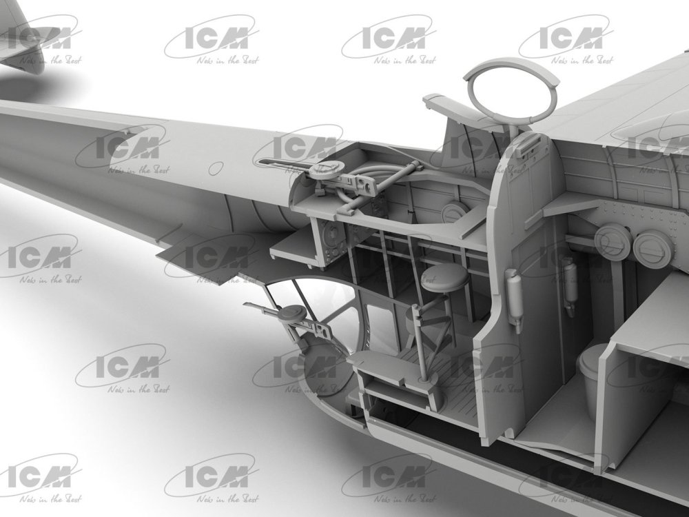
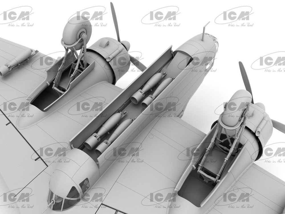
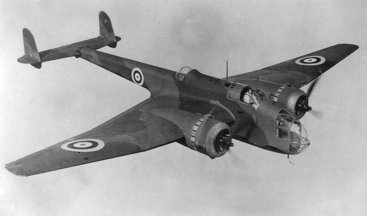
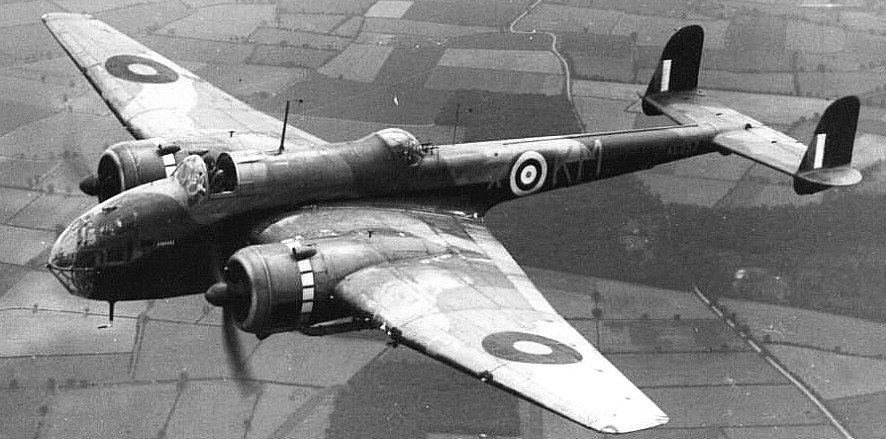
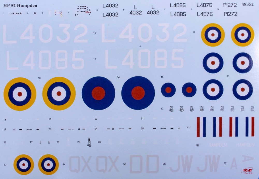
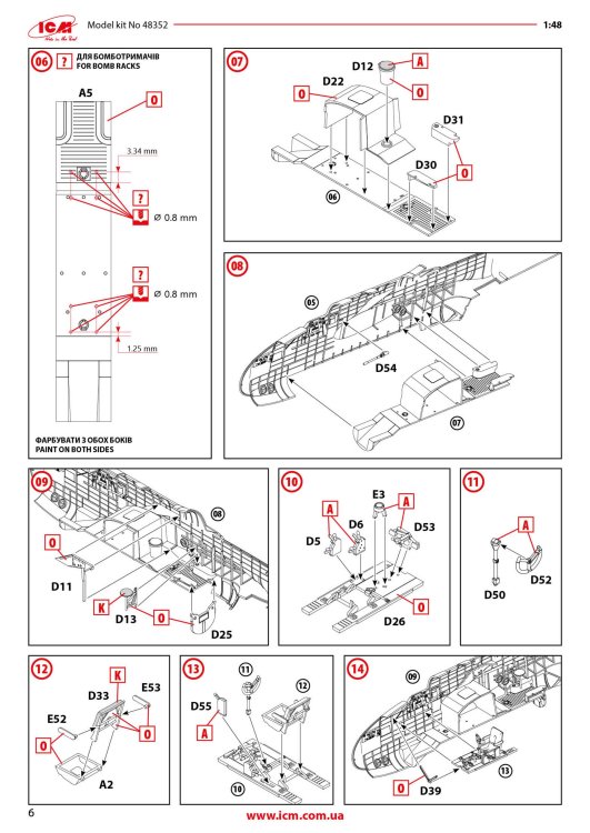
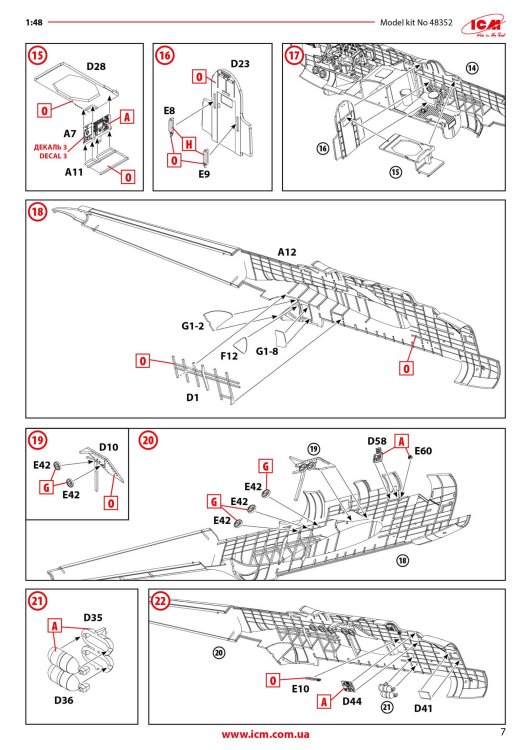
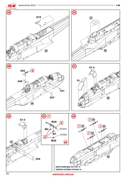
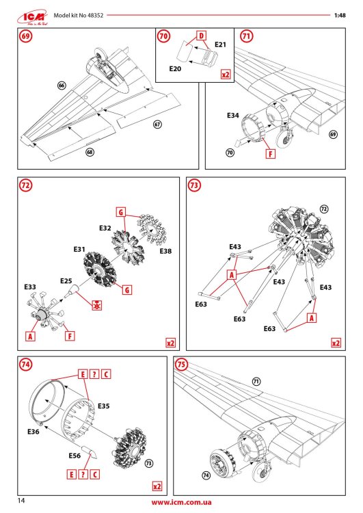
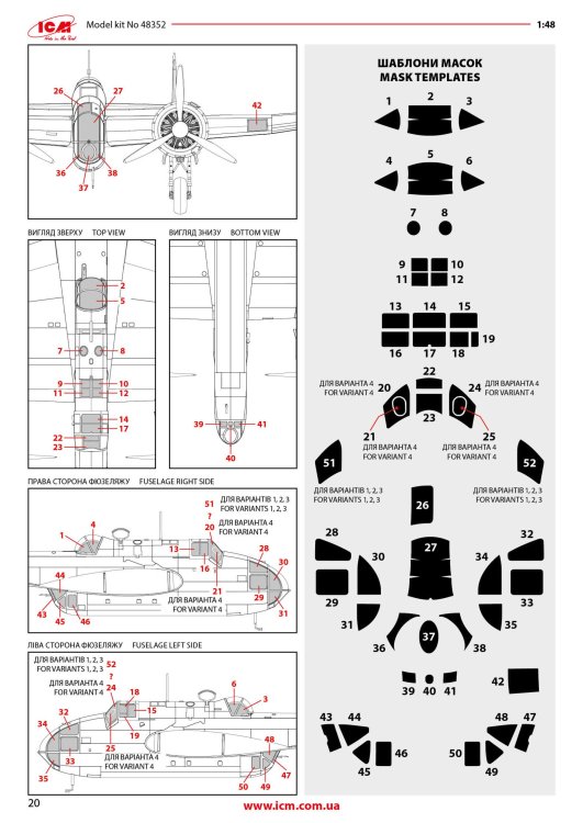
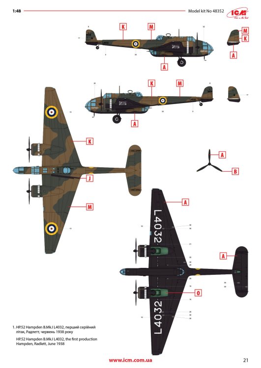
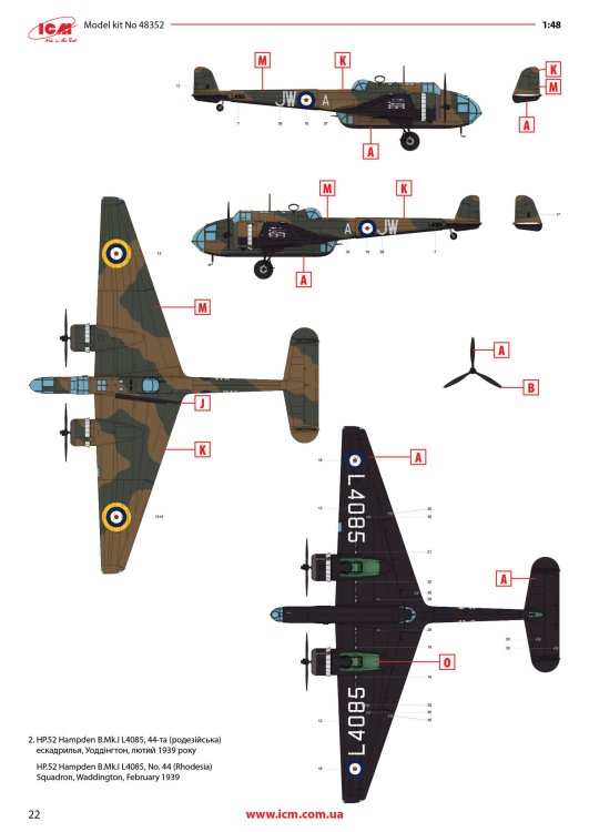
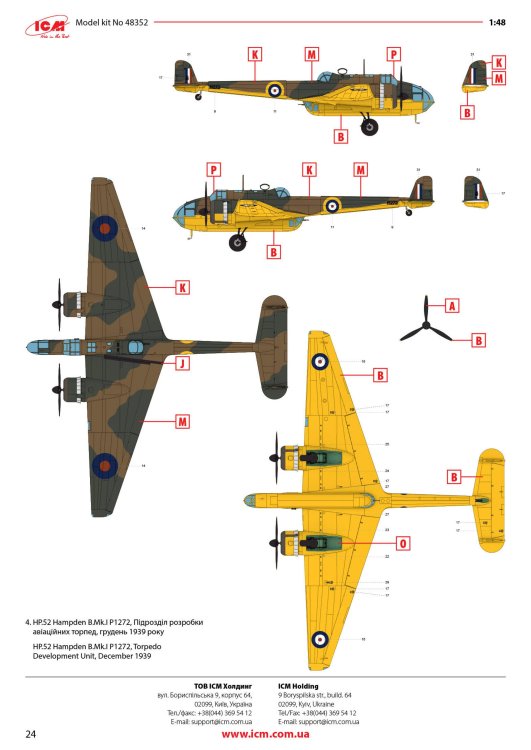
1:48 HP.52 Hampden B.Mk.I ICM Catalogue # 48352 Available from Jadlam for £62.95 he Handley Page HP.52 Hampden B.Mk.I was a British twin-engine medium bomber developed in the 1930s to meet the Royal Air Force’s requirement under Air Ministry Specification B.9/32 for a fast, modern bomber. Designed by Handley Page and first flown on 21 June 1936, the Hampden featured a distinctive slender fuselage and stressed-skin all-metal construction with two Bristol Pegasus radial engines. Its compact, streamlined shape earned it nicknames such as the “Flying Suitcase” or “Flying Tadpole” from crews, who also found its interior extremely cramped for the four-man team of pilot, navigator/bomb-aimer, wireless operator and gunner. Early production Hampden B.Mk.I’s were ordered in 1936 and began entering squadron service by late 1938 with units such as No. 49 Squadron RAF. When the Second World War broke out in 1939, the Hampden was one of the main bombers in RAF Bomber Command’s arsenal and flew a wide range of missions in the early part of the air war over Europe. It participated in night bombing operations, including the first RAF raid on Berlin in 1940 and the massive 1,000-aircraft raid on Cologne in May 1942, and was used for leaflet drops, mine-laying over the North Sea and other strategic tasks. Despite respectable speed and manoeuvrability for its time, the Hampden’s defensive armament was initially too light to protect it effectively from enemy fighters, which eventually saw its role in daytime raids fade as losses mounted. By late 1942, Hampdens were being withdrawn from front-line Bomber Command duties. After leaving the main bomber force, many Hampden B.Mk.I aircraft found a second life in Coastal Command, where they were adapted for torpedo-bomber and maritime reconnaissance roles through 1943. Modifications included deeper bomb bays to carry torpedoes and additional under-wing racks, enabling the type to serve in anti-shipping missions until the end of its operational career. A total of around 1,430 Hampden aircraft were built in the UK and Canada before production ceased in 1942, and although none remain in flying condition today, several examples survive in museums or under restoration, preserving the legacy of this early wartime workhorse. The kit As is standard with ICM kits, the Hampden is packaged into a rigid, corrugated box with a top opening flap, and a separate glossy lid that sits atop it. Inside the box, there are three resealable cellophane sleeves that contain a total of NINE medium grey styrene sprues, and a further TWO in clear styrene. The latter sprues are also wrapped in foam and separately bagged within the main sleeve too. A full colour 24-page instruction booklet and decal sheet are also included. At the time of writing, there is also a follow-up Hampden release, but despite that, the parts breakdown will require all items on this sprue to be used in this build. The most obvious are those fuselage halves, showing what a narrow width aircraft this was, and must've been fairly cramped in comparison with contemporary aircraft of this type. Unusually for ICM, the whole external airframe is also riveted! The rivet detail is perfectly subtle and will look great with a little dirt and weather over it. Internally, the fuselage has a wealth if stringer and former detail that'll be hidden amongst the avionics you will install. The long inner floor is also here, and on there other side, it doubles for the bomb bay ceiling at the rearmost area. As this is a universal part between Hampden releases, you will need to drill out a series of holes for the munitions mounts. This is clearly seen in the manual. Also moulded here are the aft access hatch, open/closed bomb bay door options, radio equipment, and aileron wing mounts. This is the first of two sprues that contain wing parts; starboard upper and port lower. Wings are moulded with separate ailerons and landing flaps of which you can see them here, typically provided as halves. The tail lower fin halves are moulded here too. The next sprue contains the other two wing halves. You will find more control surface parts here, as well as the rudders and internal wing reinforcing structures. Most of the cockpit elements are to be found on this sprue, as well as bulkheads and stabiliser upper/lower halves. There are TWO of these sprues included, containing many of those items duplicated around the airframe, such as engines, props, main gear bay doors, cowl sections, fins, main gear struts, and wheels. Detail is excellent throughout with some decals also supplied to supplement some of the finer cockpit detail parts. THREE of these sprues are included, but quite a few of the parts here will be relegated to your spares box. Bomb racks are moulded on this sprue, for use with this release. Both of these sprues are crystal clear; something I can never clearly show in my photos. Some of these parts have options present too, depending on which machine you will opt to build. Framing lines are also sharp, meaning masking should be quite easy. Mask templates are included in the manual, but to be honest, I'd likely decide to use a set of pre-cut masks from Eduard etc. Decals A single decal sheet is included that contains markings for FOUR machines. Printing is excellent, with the inking being thin with solid colour, minimal carrier film and perfect registration. Marking options are: HP.52 Hampden B.Mk.I L4032, the first production Hampden, Radlett, June 1938 HP.52 Hampden B.Mk.I L4085, No. 44 (Rhodesia) Squadron, Waddington, February 1939 HP.52 Hampden B.Mk.I L4076, No. 50 Squadron, Waddington, September 1939 HP.52 Hampden B.Mk.I P1272, Torpedo Development Unit, December 1939 Instructions The 24 page manual is printed in full colour, with clear line drawings for each step of construction. Plenty of clear annotation is supplied for specific details, and colour call-outs are supplied for ICM's own paint range. I've not tried those yet and it'd be quite interesting to see how they hold up against my regular brands. A colour page is supplied for each scheme, shown above. A parts maps is also included for each sprue. Conclusion I've never built a Hampden in any scale or material before. It was always one of those types for which was only available either in vac or limited run styrene with crap metal castings with bad vac form canopies. Being able to buy one as a regular styrene kit with loads of in-the-box details was a dream come true, so you can imagine how it felt to know ICM was sending one out to me. Nothing in this kit disappoints, and it even has plenty of exterior rivet detail too, so need need for a few sessions with Rosie. I absolutely love this release, from the subject, to the engineering and amazing depth of detail. The schemes are excellent choices too, with that yellow belly one being really appealing to me. My sincere thanks to ICM for sending this sample for review on Large Scale Modeller. To buy, click the link at top of article.


-
As soon as I finish my current project in a couple of months, this is being cracked open!
-
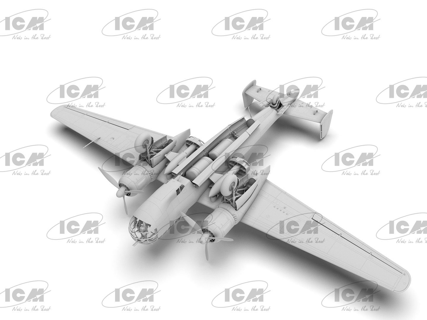
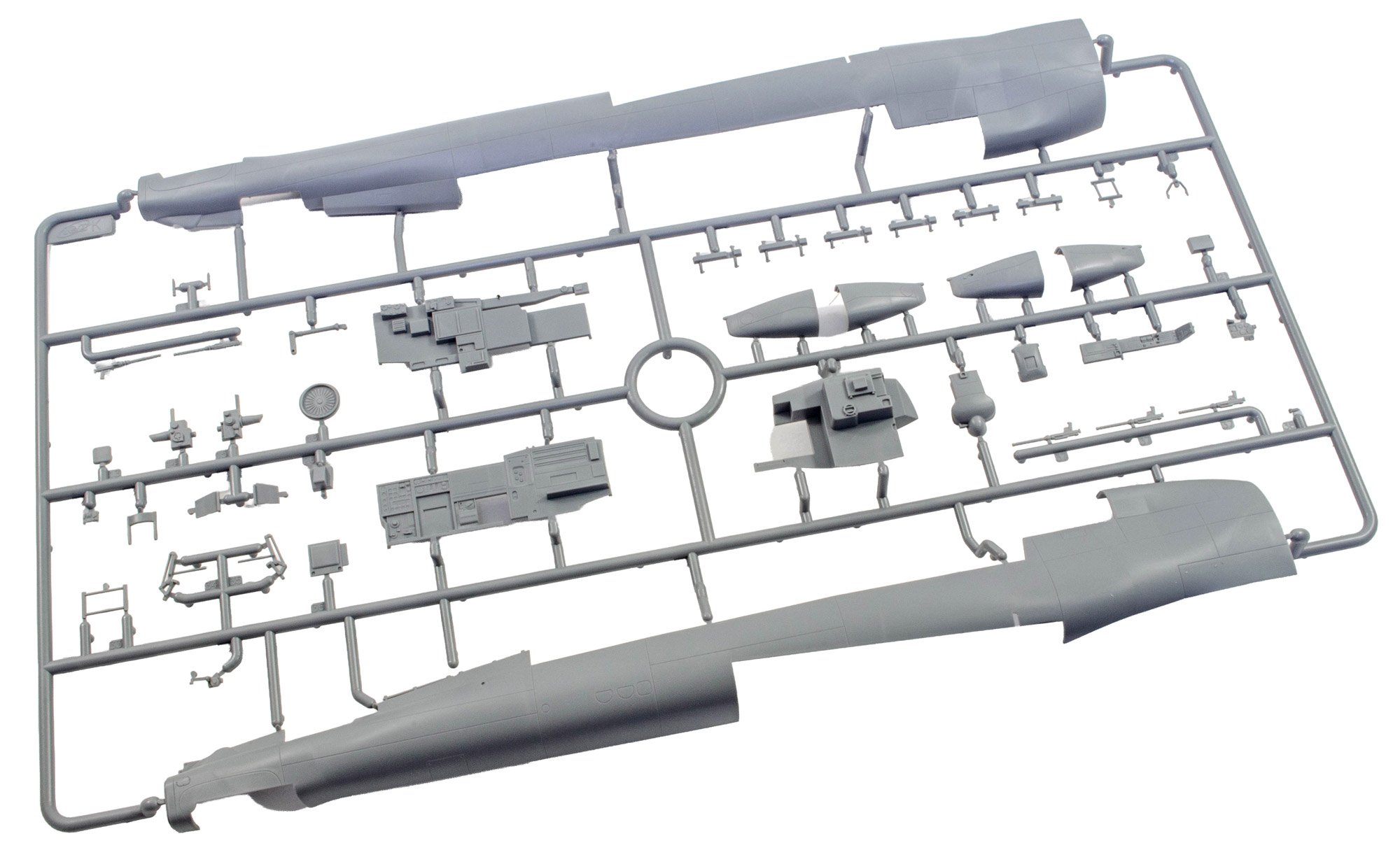
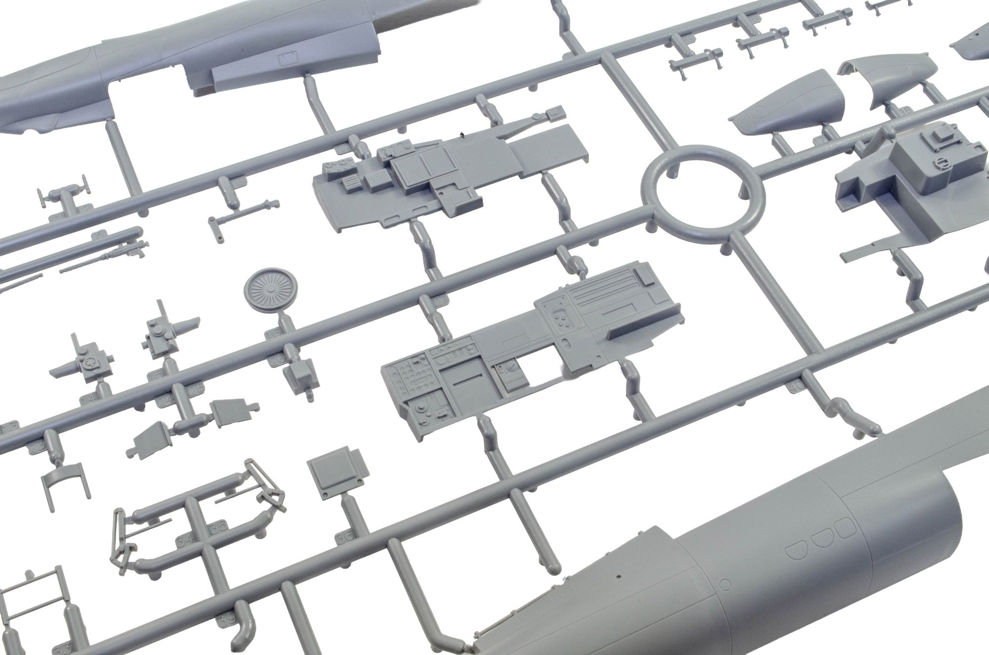
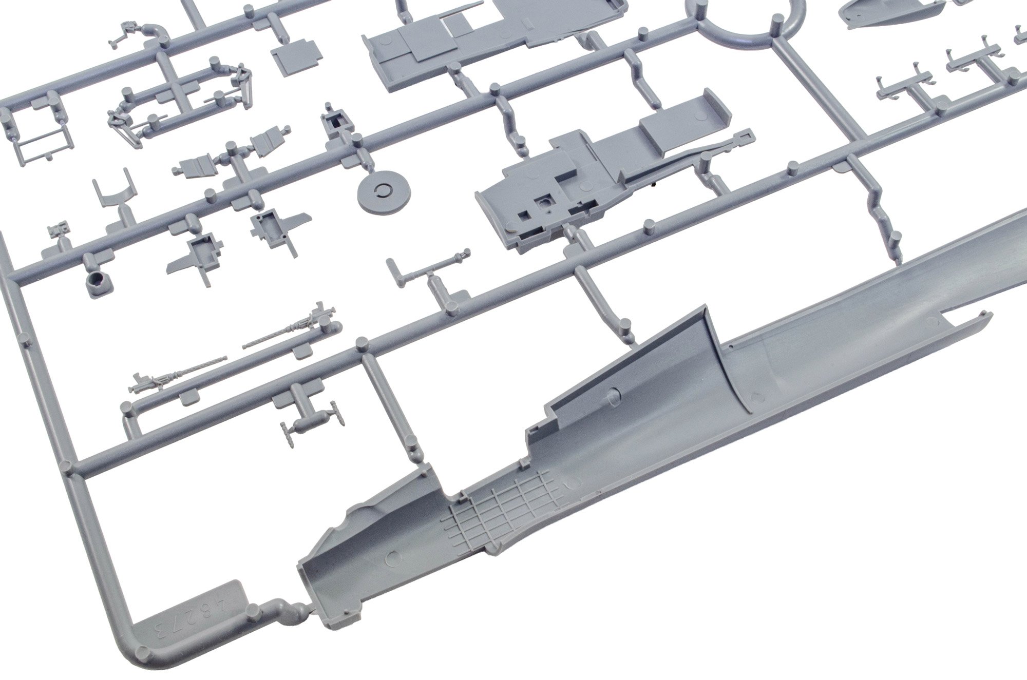
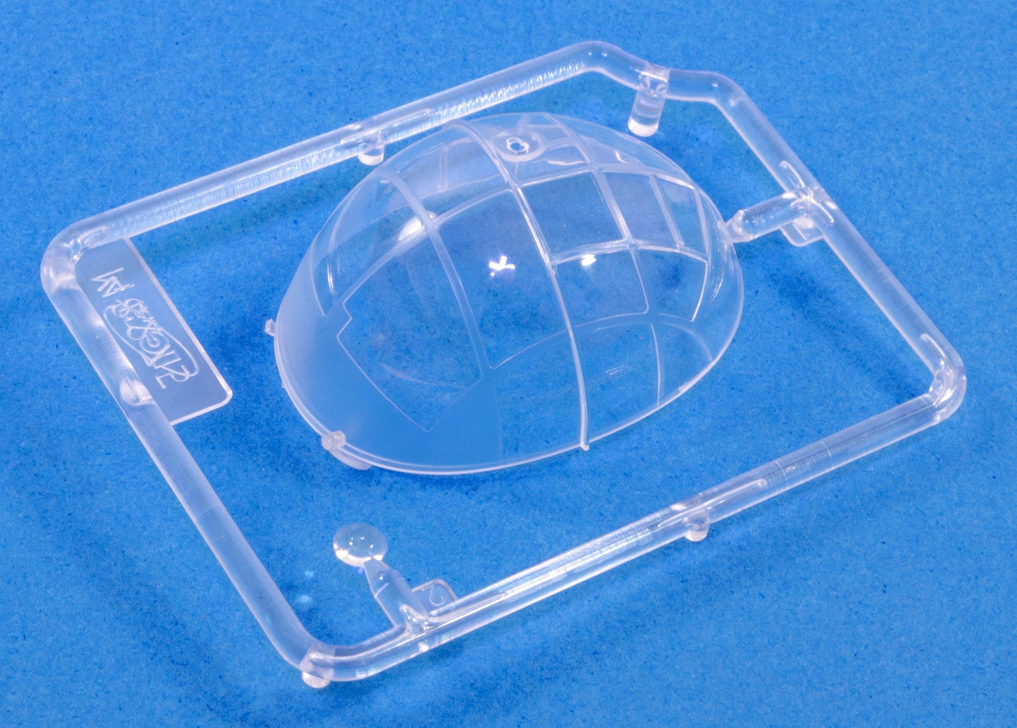
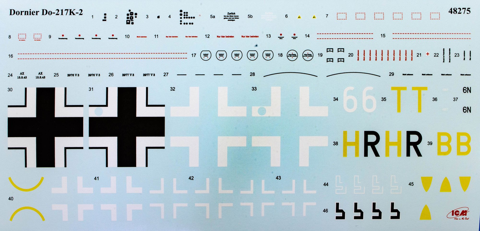
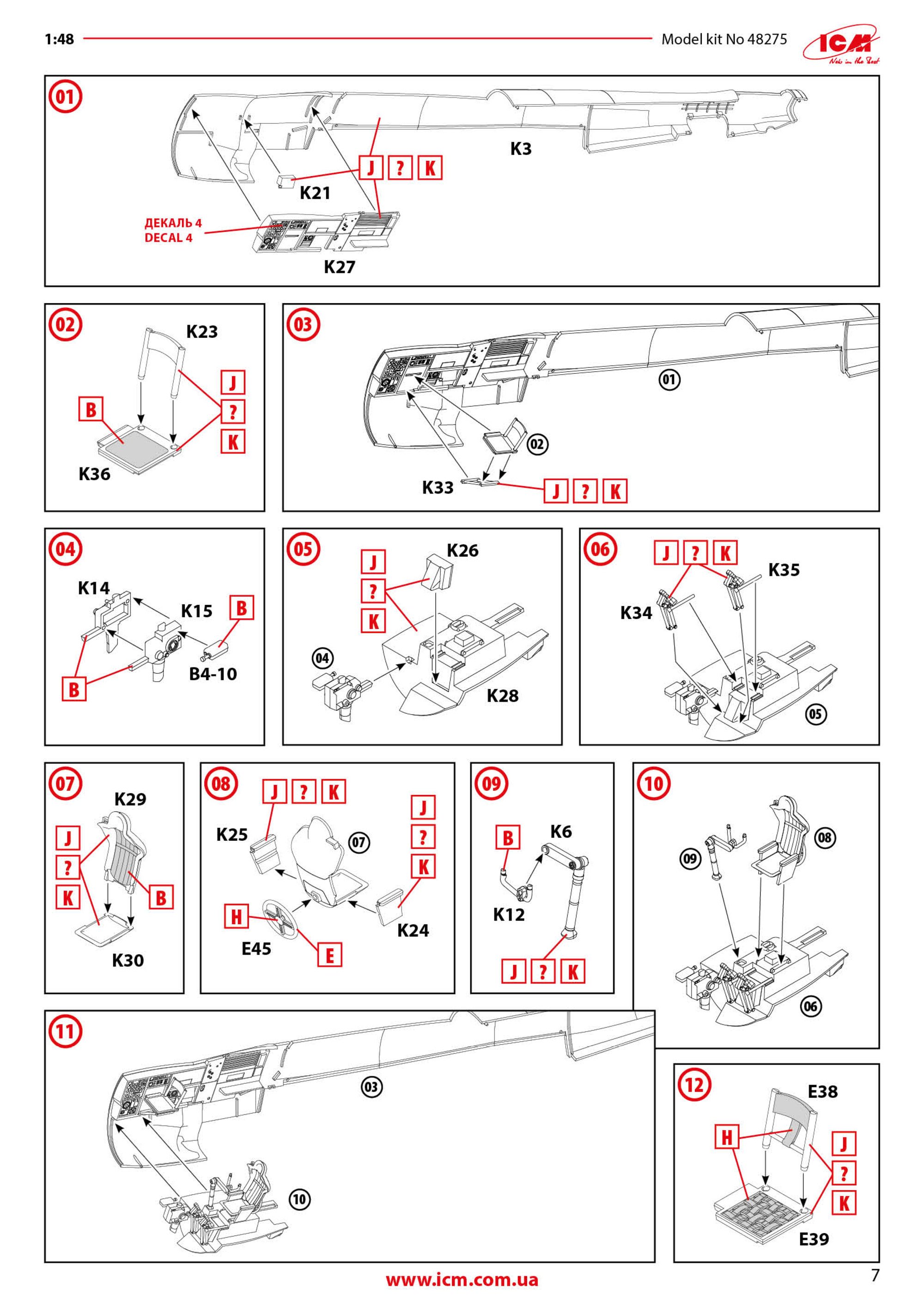
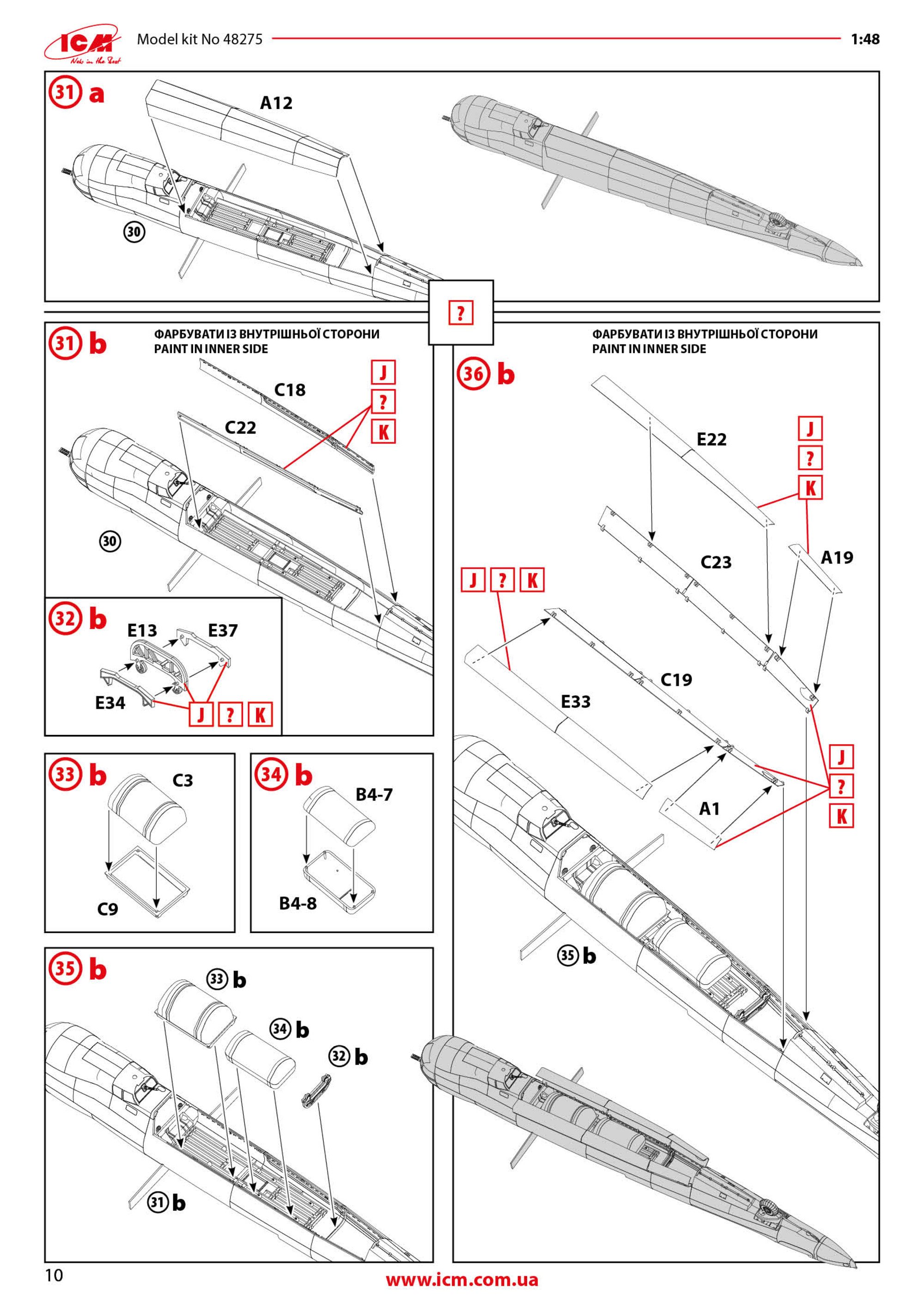
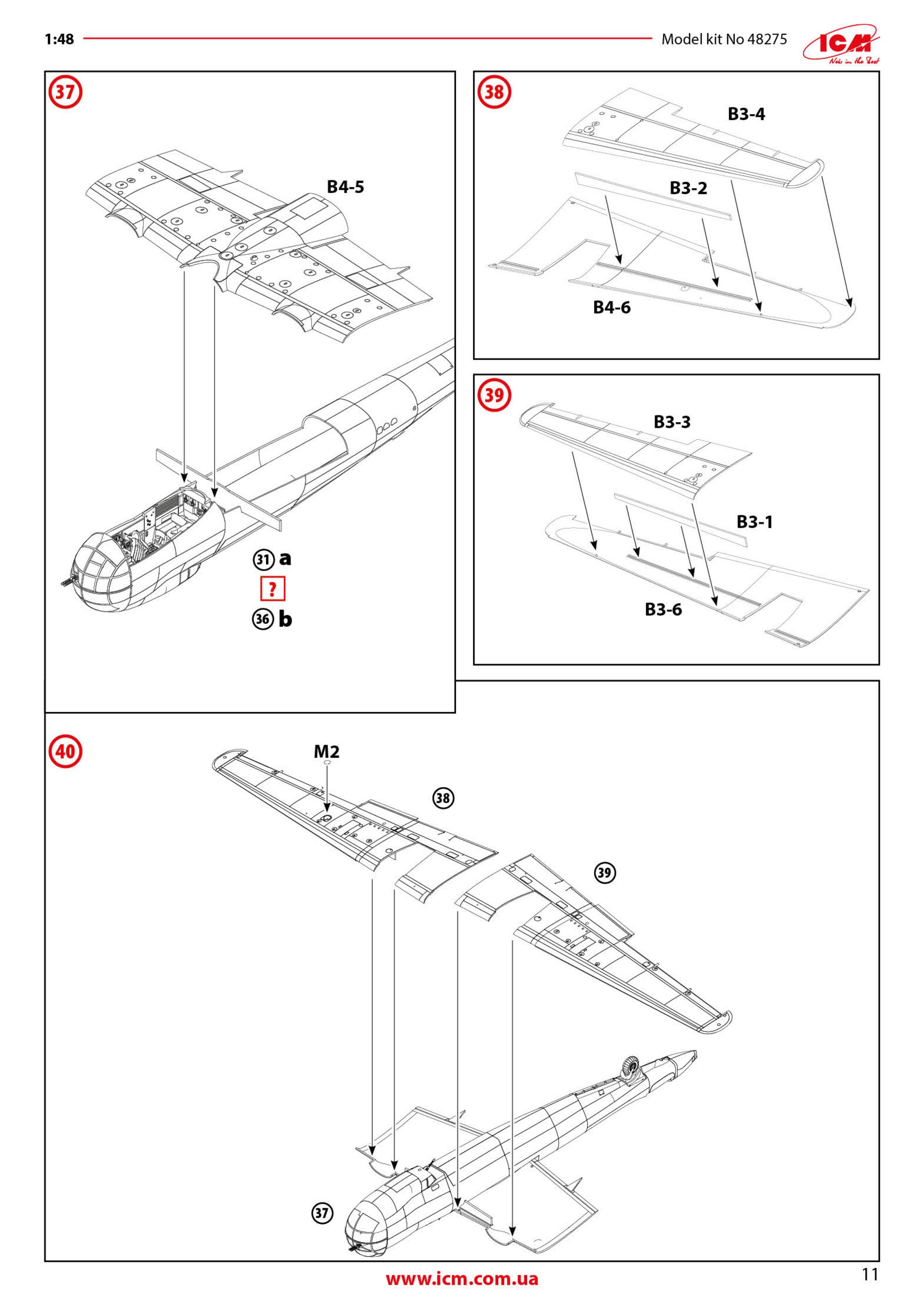
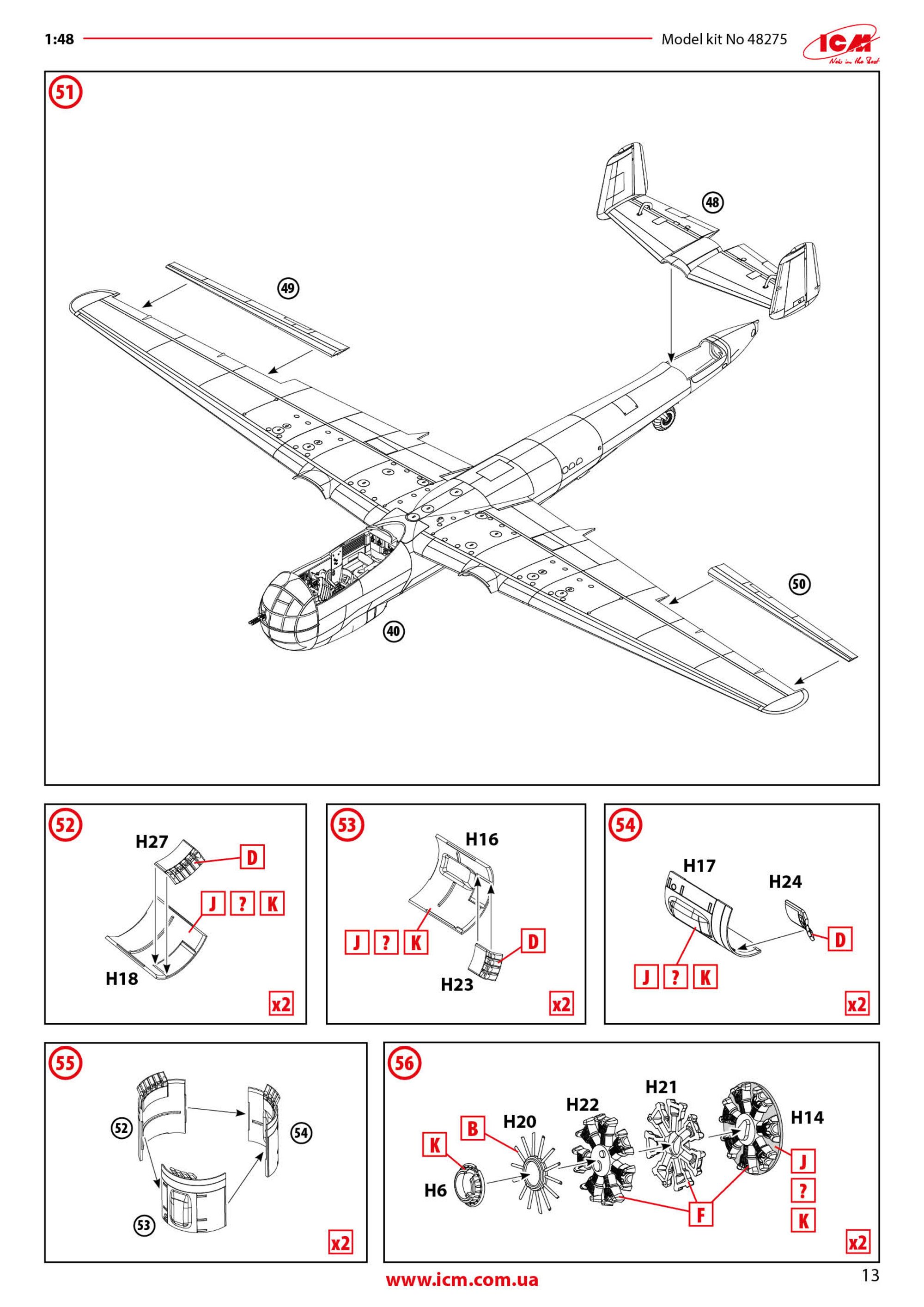
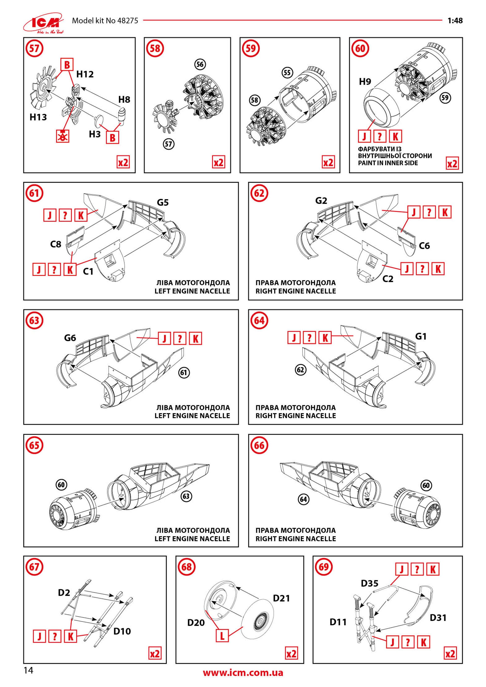
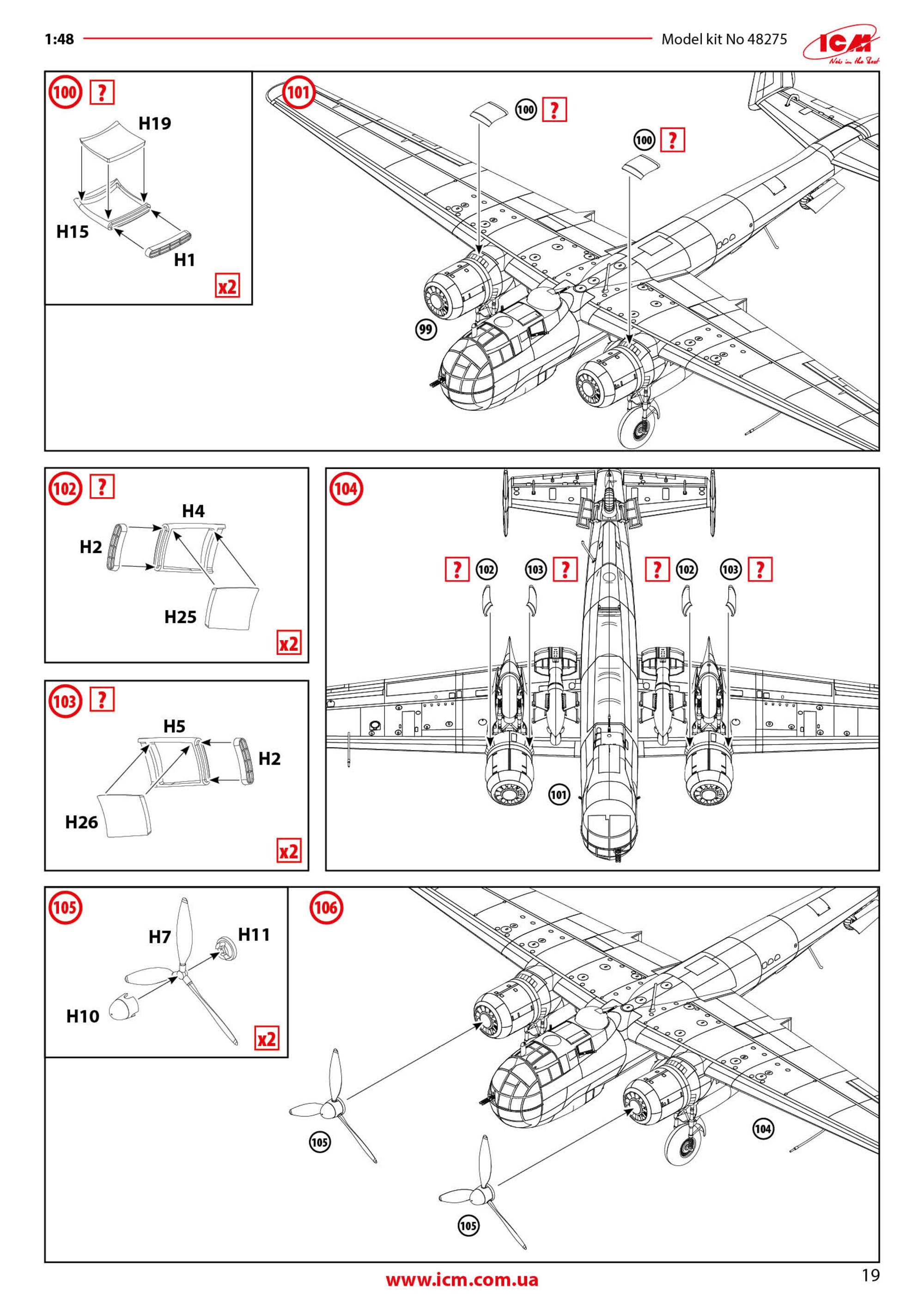
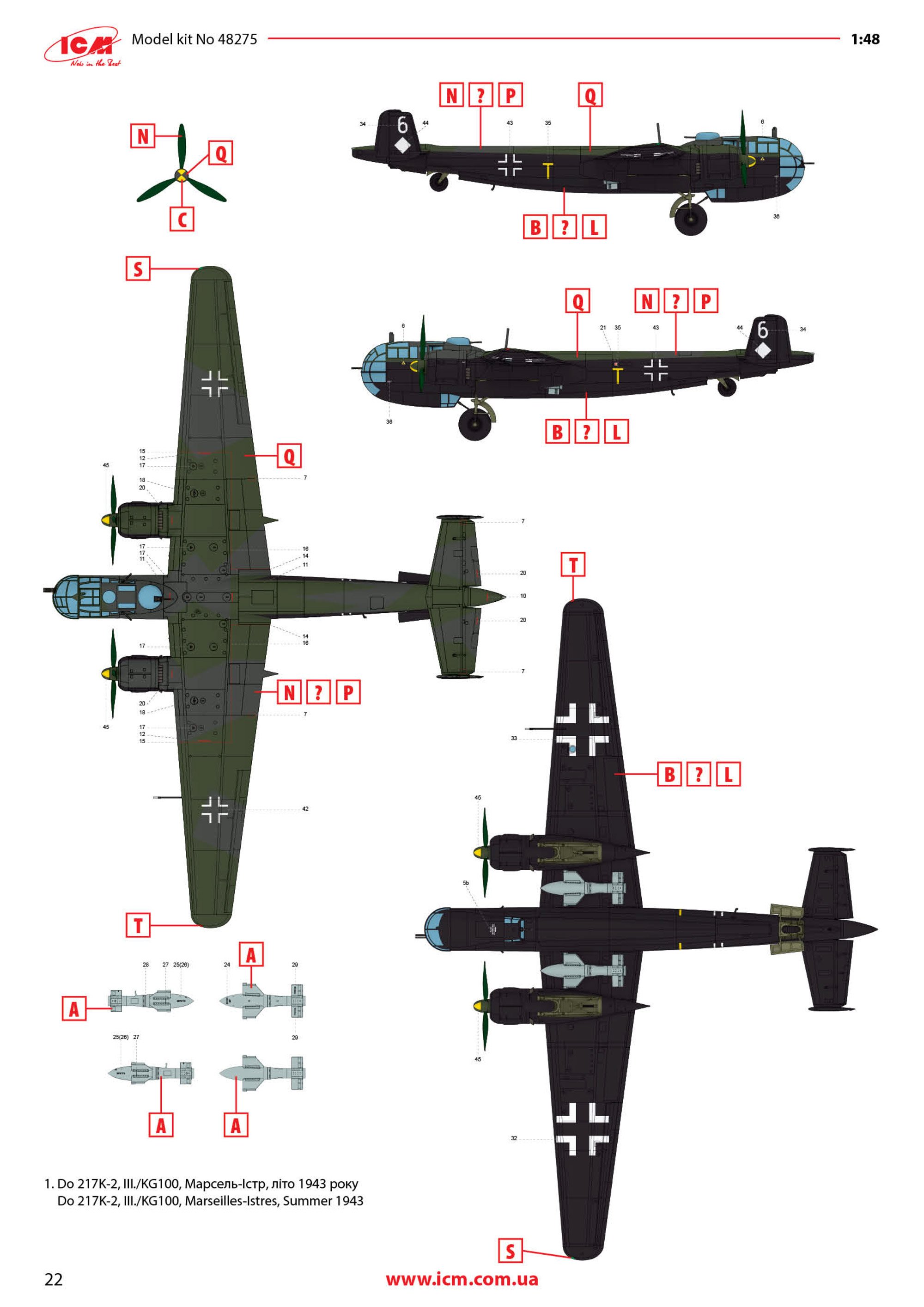
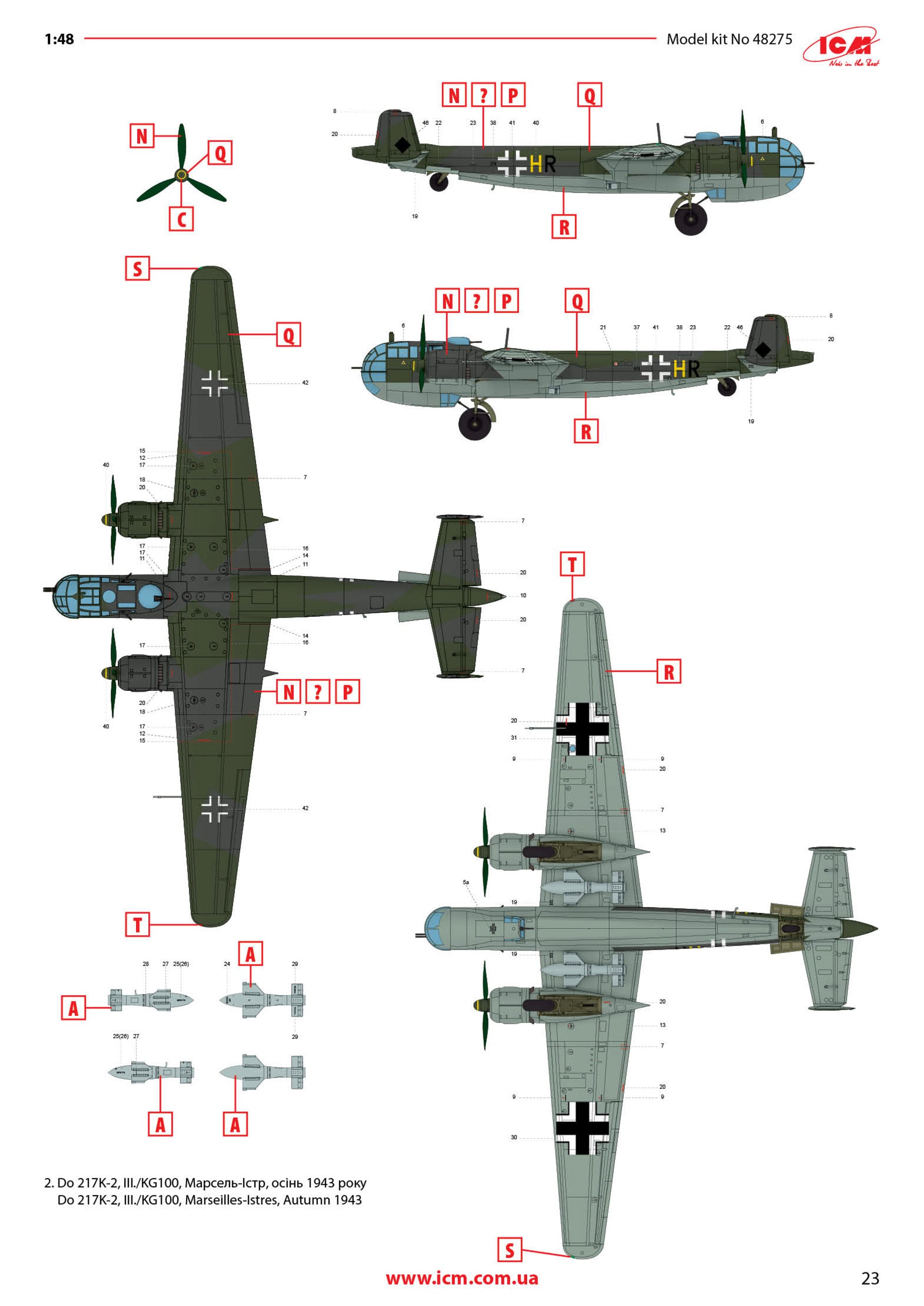
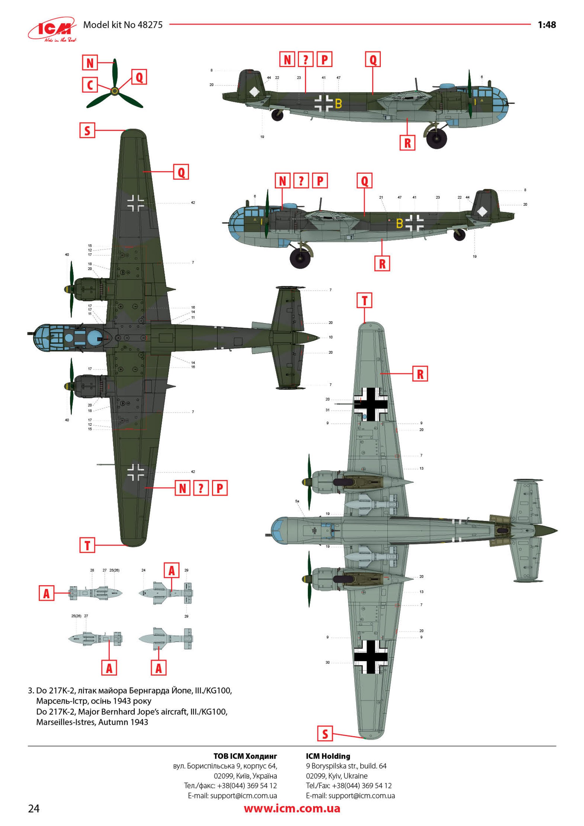
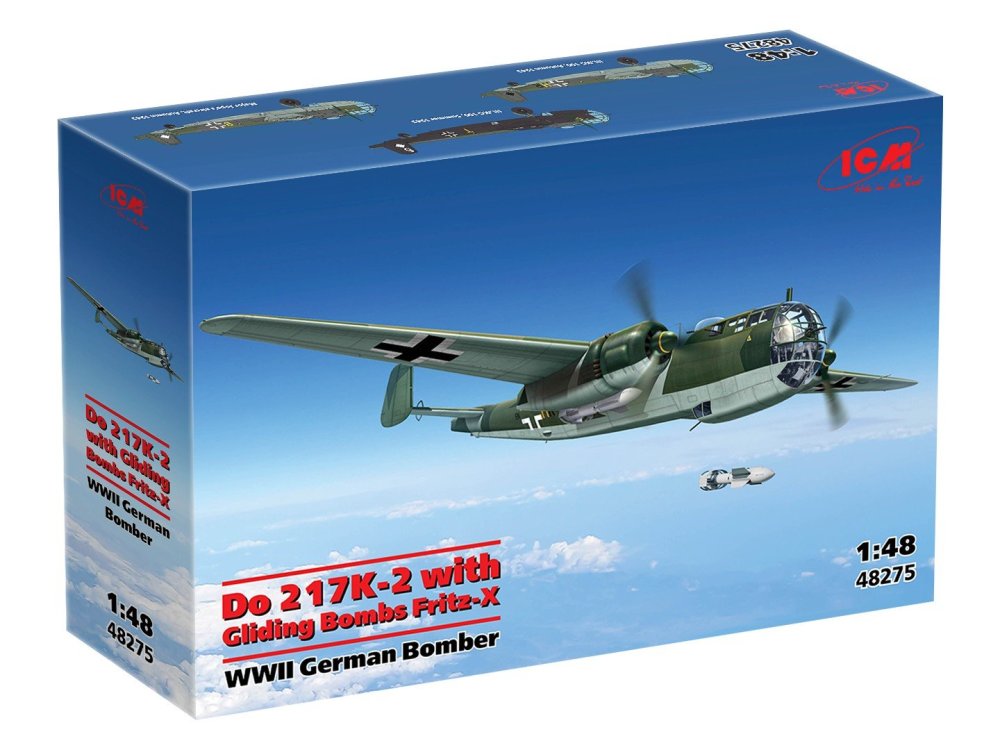
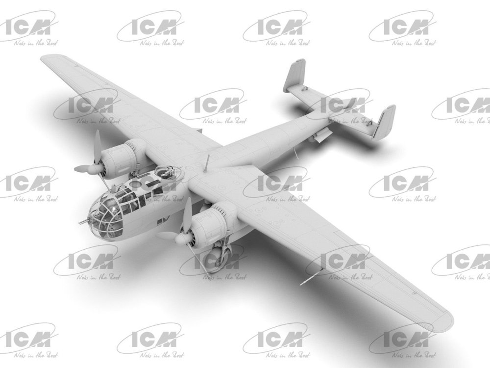
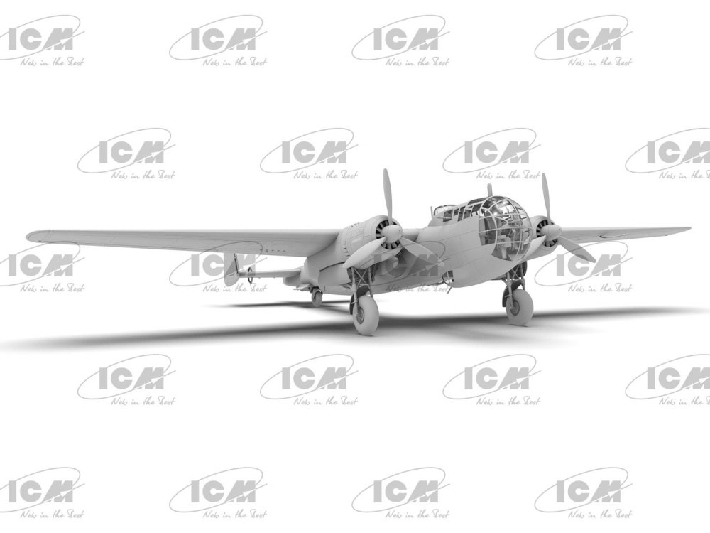
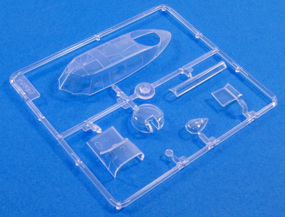
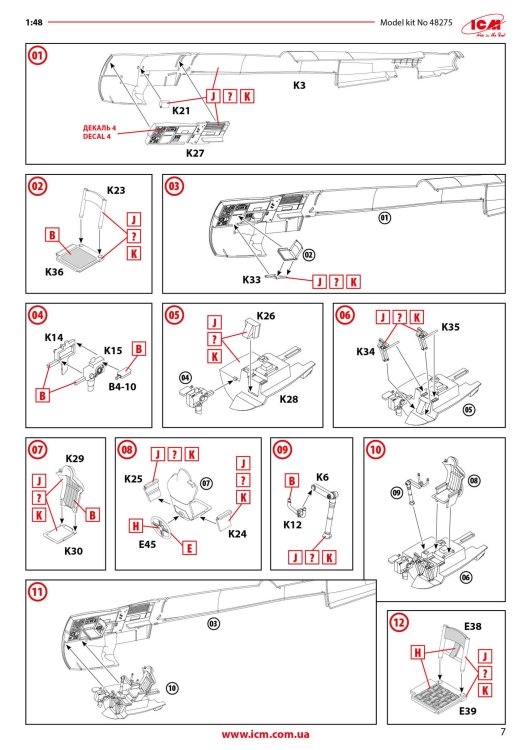
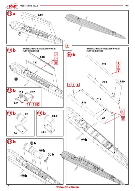
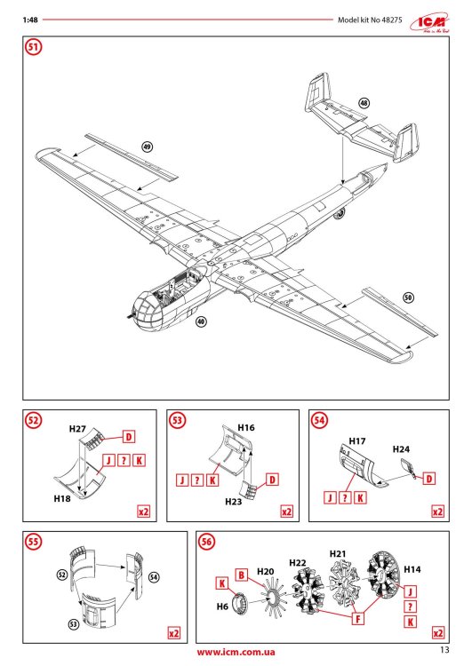
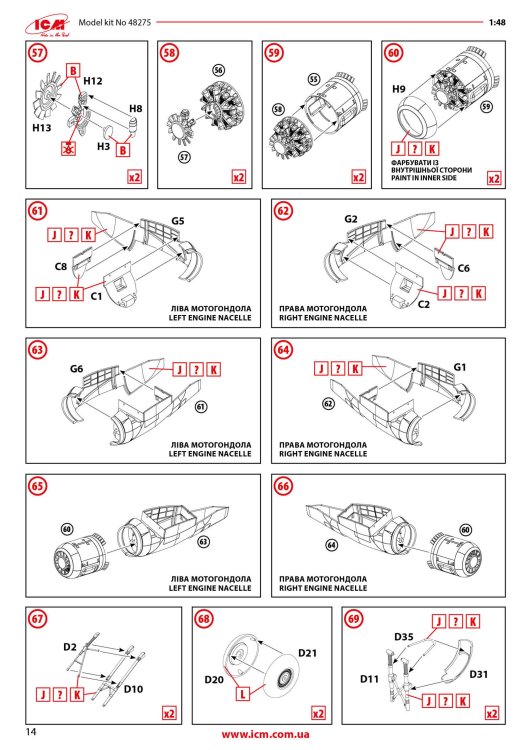
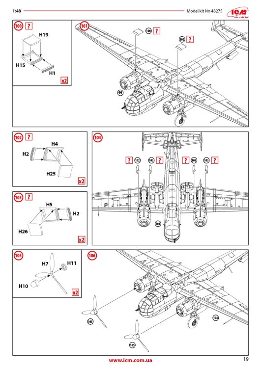
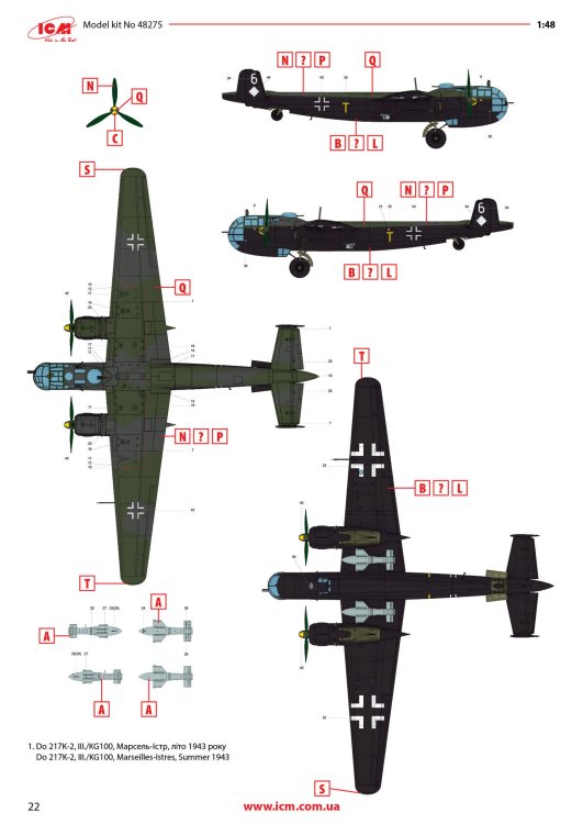
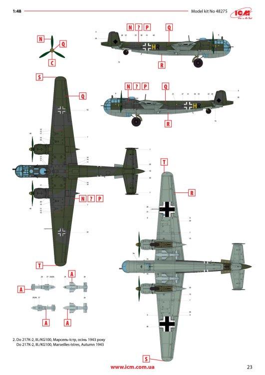
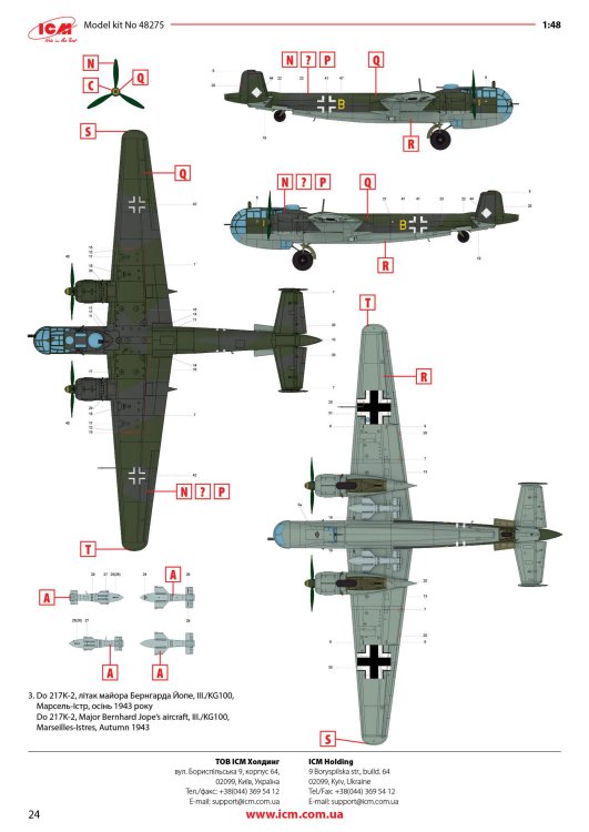
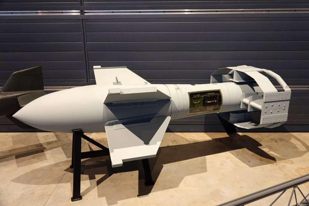
1:48 Do 217K-2 with Gliding Bombs Fritz-X ICM Catalogue # 48275 Available from Stockton Modeller for £67.99 The Dornier Do 217K-2 was a specialised variant of the German Dornier Do 217 bomber, developed during World War II as part of Germany’s effort to enhance its long-range bombing and anti-shipping capabilities. The Do 217 series itself evolved from earlier Dornier designs and was intended to replace older medium bombers such as the Do 17. The “K” series featured a redesigned glazed nose and improved aerodynamics, while the K-2 variant was specifically modified to carry the revolutionary Ruhrstahl Fritz X radio-guided bomb. Introduced in 1943, the Do 217K-2 represented one of the most advanced precision-strike platforms in the Luftwaffe’s arsenal. The defining feature of the Do 217K-2 was its role as a carrier for guided munitions, particularly the Fritz X, an armour-piercing bomb designed to destroy heavily armoured naval targets. To support this mission, the aircraft was equipped with specialised radio-control systems and carried trained operators who guided the bomb visually after release. The K-2 could typically carry two Fritz X weapons under its wings, giving it unprecedented striking power against Allied warships. Powered by BMW 801 radial engines, the aircraft had sufficient range and altitude capability to conduct attacks from outside most naval anti-aircraft fire, although it was still vulnerable to enemy fighters. The Do 217K-2 achieved its greatest success during operations in the Mediterranean in 1943, most notably in the sinking of the Italian battleship Roma after Italy’s surrender and in attacks against Allied shipping near Italy and southern France. These missions demonstrated the potential of precision-guided weapons decades before they became standard in modern warfare. However, the aircraft’s impact was limited by Allied air superiority, electronic countermeasures, and production constraints. By late 1944, increasing losses and fuel shortages reduced its operational effectiveness. Despite its relatively short service life, the Dornier Do 217K-2 remains historically significant as one of the world’s first operational platforms for guided weapons and a precursor to modern precision strike aircraft. The kit This kit is packaged into one of ICM's deeper boxes. The rigid, corrugated box has an upper flap lid, and a separate, glossy lid which shows the Do 217K-2, releasing a Fritz, to stunning effect. Under the hood, there are TWELVE sprues of medium grey styrene, and THREE crystal clear sprues. The latter are individually packed so to prevent scuffing. All sleeves are tough cellophane with a self-sealing adhesive strip. An instruction booklet and a decal sheet complete this release. This kit actually has two sets of fuselage halves, but THESE parts are the ones you will use. The other can go to your spares box. In fact, these release has a number of unused parts which hark back to the numerous previous versions of this Dornier family. The expansive Dornier cockpit with that greenhouse canopy, will need plenty of detail tucked away below it, and some of that cab be found here such as the cockpit sidewall panels, cockpit floor, seats, bomb aiming device, MGs, bulkhead, consoles, control column etc. Outside of the cockpit, there are very few parts, but you will find the two-part tail cone. Externally, the whole model has beautifully fine panel lines etc., but there isn't any rivet detail, which is quite common with ICM releases. There are two of these sprues, and the parts breakdown is pretty obvious. You have engine cowl sections, and all the parts to build up the two BMW 801D engines themselves. Exhaust arrays and the three-blade props are also found here. When you consider this Dornier family, there were so many variations between certain types, and many similarities. Not all of them seem logical, so ICM has included a good number of parts on common sprues that won't be used here, but with others that will need to be used. This sprue is a good example of this. The four parts used here are the engine/gear nacelles with some lovely detail, with an unused nosecone tucked in between them. On this release, the upper wing is built from three parts. The first is the upper centre section, and then the extended wing panels to outboard side of this. One panel is moulded here, as are both sets of ailerons halves, belly fuel tank, and canopy periscope parts. Of course, these fuselage halves will NOT be used with this release, but almost everything else is. Clearly seen here are the full span upper tailplane and lower halves, as well as the fins and rudder parts. more bulkheads, bomb/fuel bay ceiling and the single piece belly for if you simply wish to depict the doors in the closed position. Referencing parts that varied between types, you will find unused parts here for the cockpit side consoles, plus those large nacelle sections. You've already seen the parts this release will use, so these others can be relegated to the spares box.That includes the small nose cone nd bulkhead. What will be used are nacelle bulkheads , secondary belly fuel tank, forward wing spar/bulkhead combo, tailwheel well, and multiple belly bay door parts for if you pose in the open position to show all that internal detail. Again, there are TWO of these sprues, duplicating multiples of items found throughout the build, such as wheels, gear strut parts etc. However, most parts here will NOT be used in this release, including those impressive four-blade props. As there two Fritz-X gliding bombs slung underneath the wings of this beast, there are TWO sprues to cater to them. Impressive! Just a few parts not used here, so plenty will make their way onto your finished Dornier. Used parts are main gear bay doors, more cockpit detail (seats, MGs etc.), plus more belly door parts and belly details, elevator halves, etc. Very self-explanatory. The remaining lower extended wing panel and both upper panels, along with trailing edge inserts and both Fritz mounts. External detail is commensurate throughout. Landing flaps are moulded in the closed position, although I'm sure Eduard will have something for you if you wish to pose them in a dropped position. THREE clear sprues are provided. All are crystal clear and exhibit fine framing. Solid colour areas are shown as frosted so the finish will match the airframe. Again, several parts won't be used with the 217K-2. Make sure you use the right parts! Decals One single decal sheet is included for all three schemes. The printing is excellent, with solid colour, minimal carrier film and a load of stencils and cockpit decals also included. The three schemes supplied are: D o 217K-2, III./KG100, Marseilles-Istres, Summer 1943 Do 217K-2, III./KG100, Marseilles-Istres, Autumn 1943 D o 217K-2, Major Bernhard Jope's aircraft, III./KG100, Marseilles-Istres, Autumn 1943 Instruction A full colour 24-page instruction manual is included which depicts the build as clear line drawings with obvious annotation for colour callouts etc. Colours are given for ICM's own paint range. Parts maps are included as well as those full page scheme sheets that I included above. Conclusion Out of all of the Dornier 17/215/217 lineage, I didn't think I'd ever see a long-span Do 217, especially with Fritz slung below the wings. Not only that, but in 1:48 too. That extra span makes this quite an imposing model in this scale, with a span of 524mm! I have a number of ICM Dornier kits either ICM boxes or as 3rd party releases, so I sort of knew what to expect here, but I do think this has surpassed my expectations. I've been away from real plastic modelling for around 6yrs, and I do know this will be my first foray back into building. I really can't wait! The detail is excellent throughout although I will be using my Rosie to rivet the airframe for some extra interest.


-
How easy would it be to retrofit a Trump or Revell kit to a prototype?
-
Cheers!
-
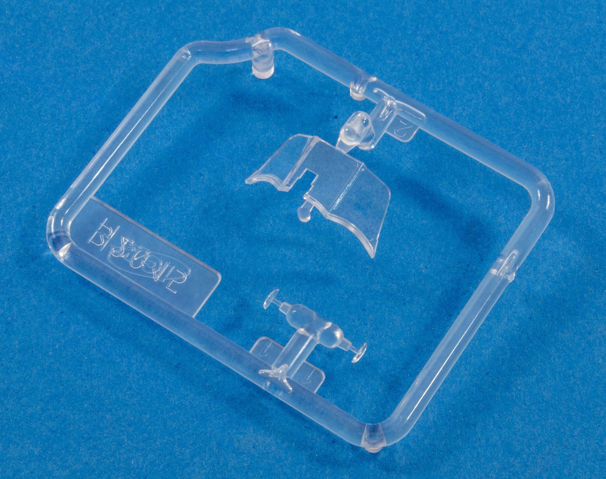
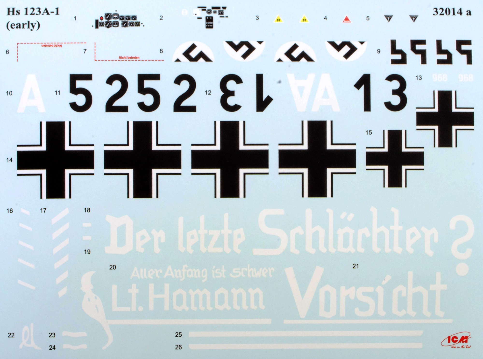
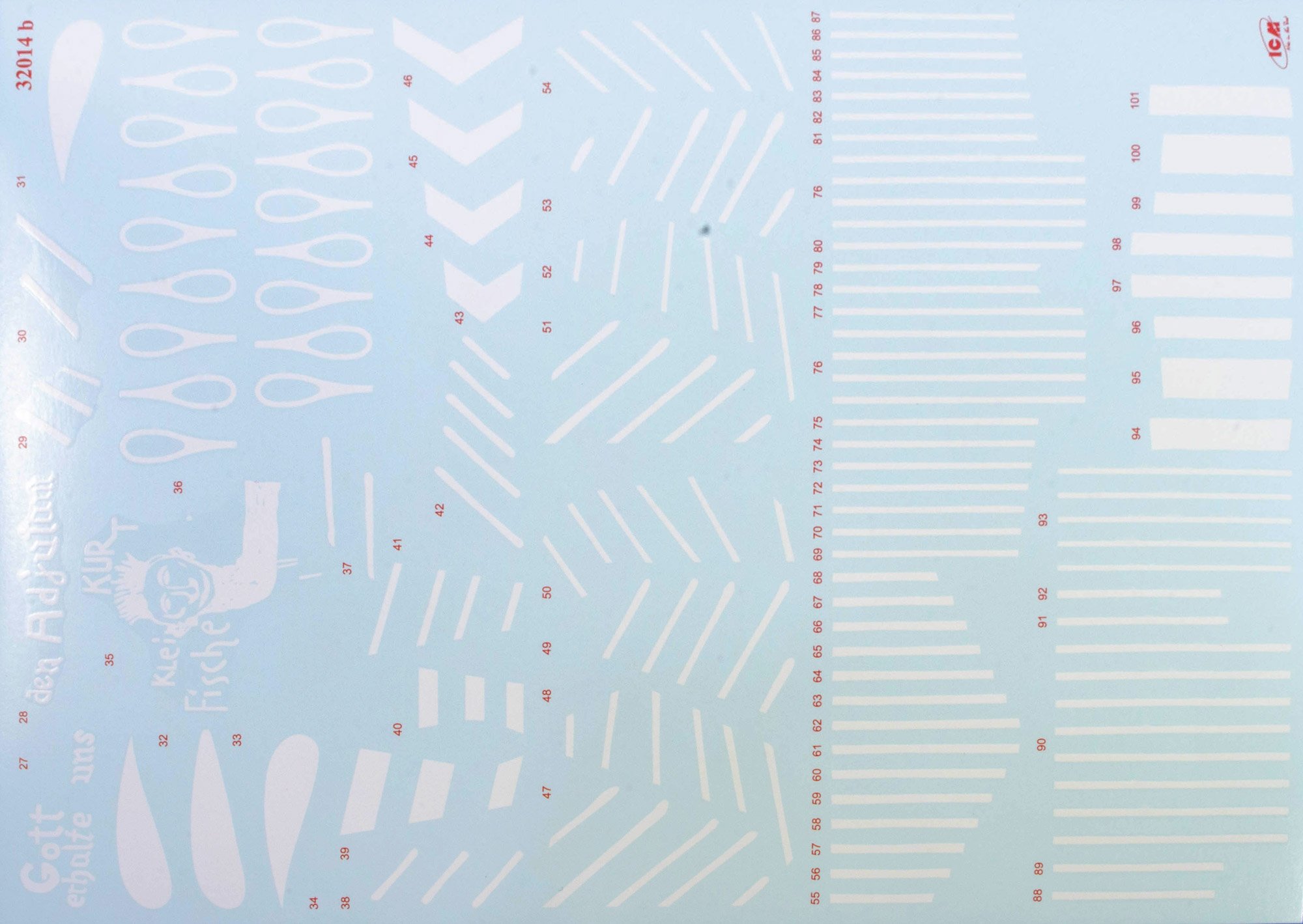
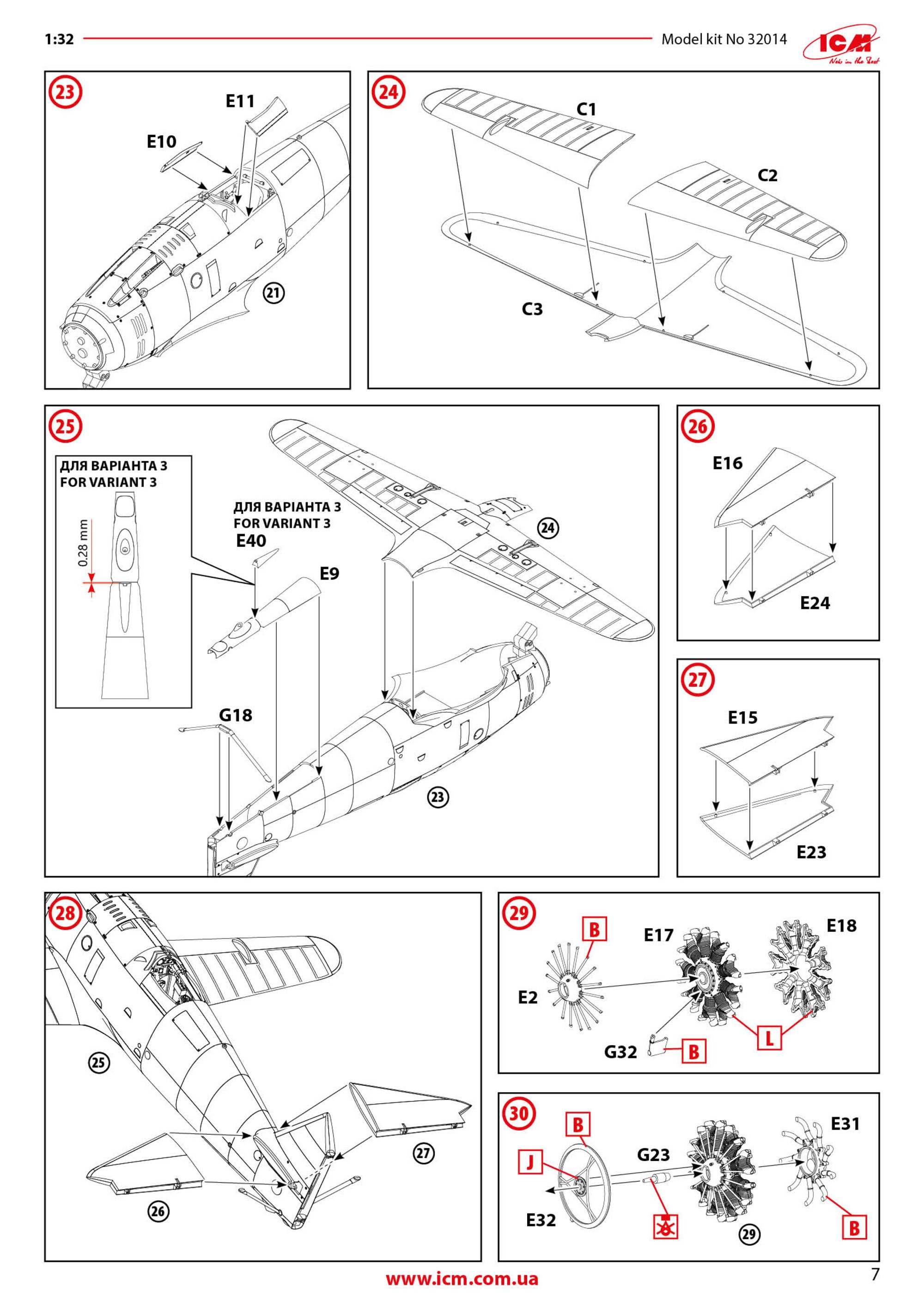
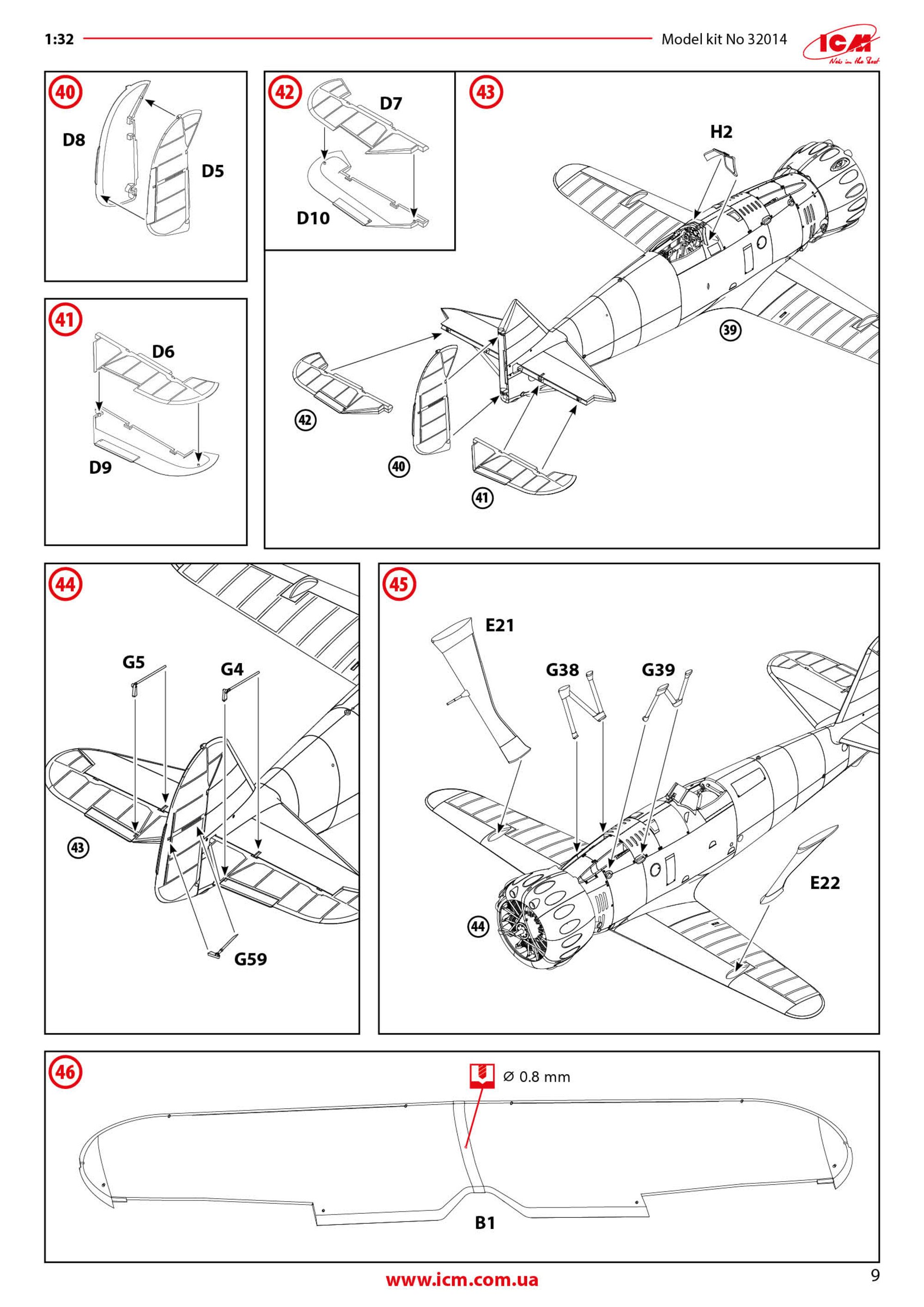
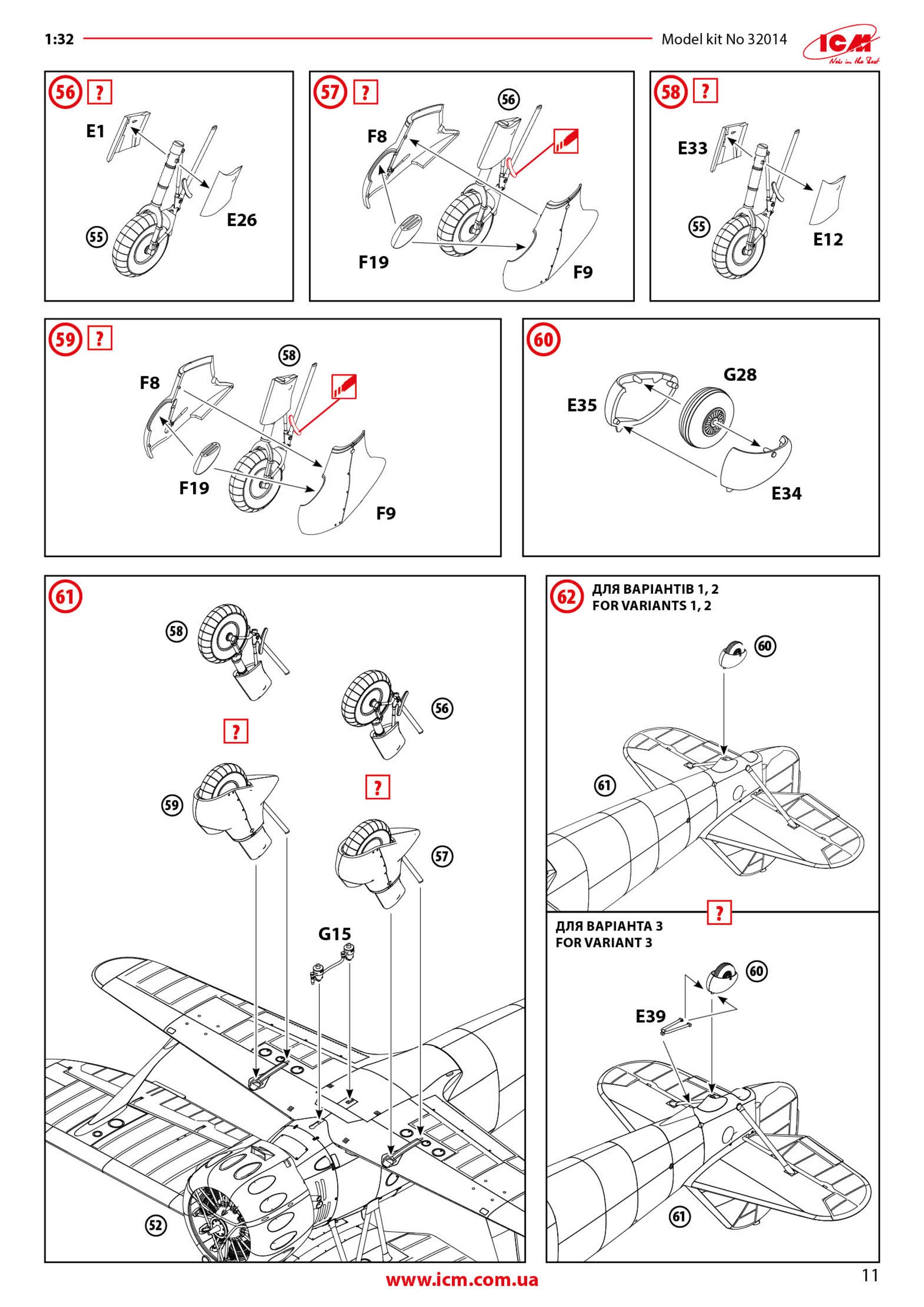
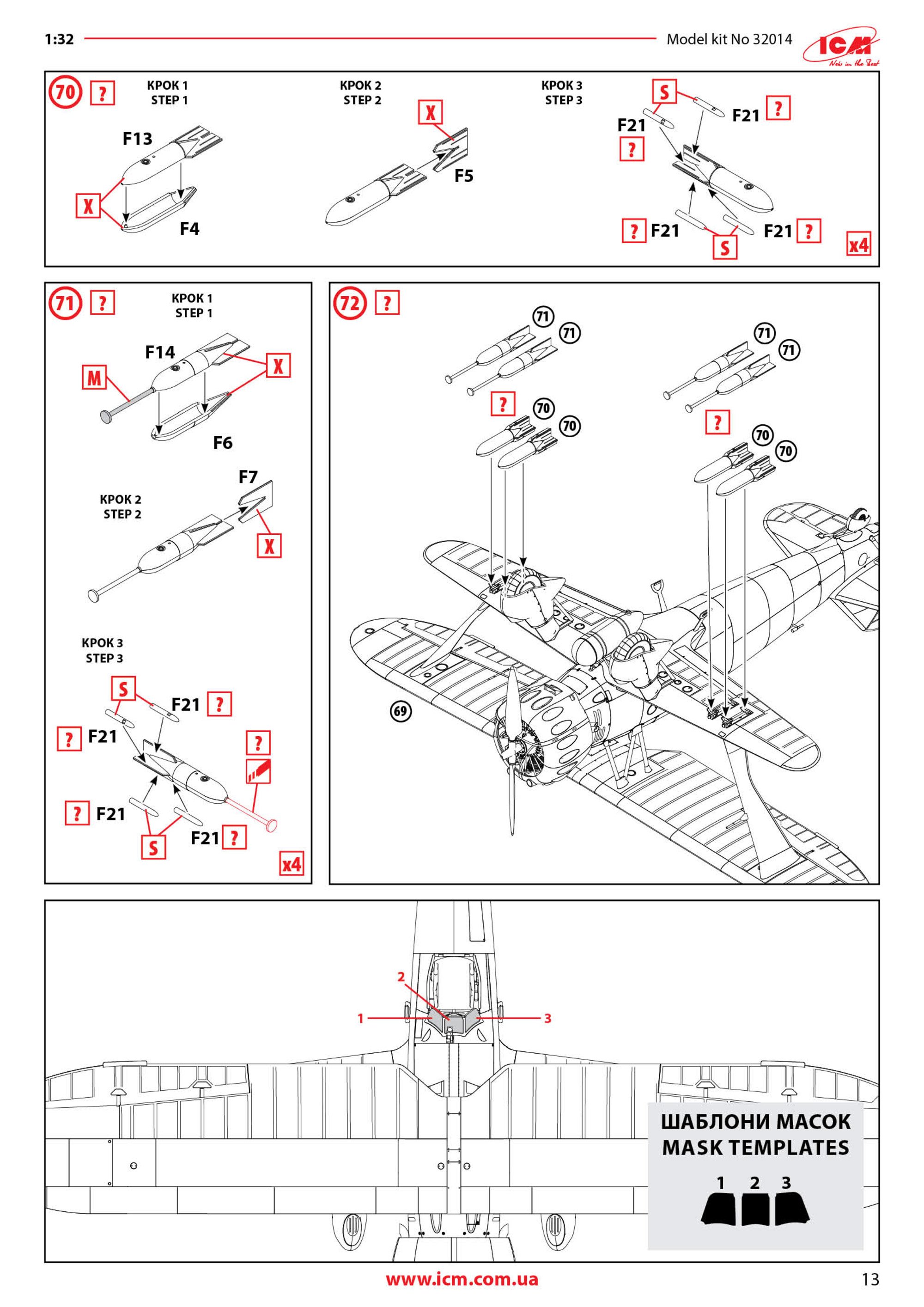
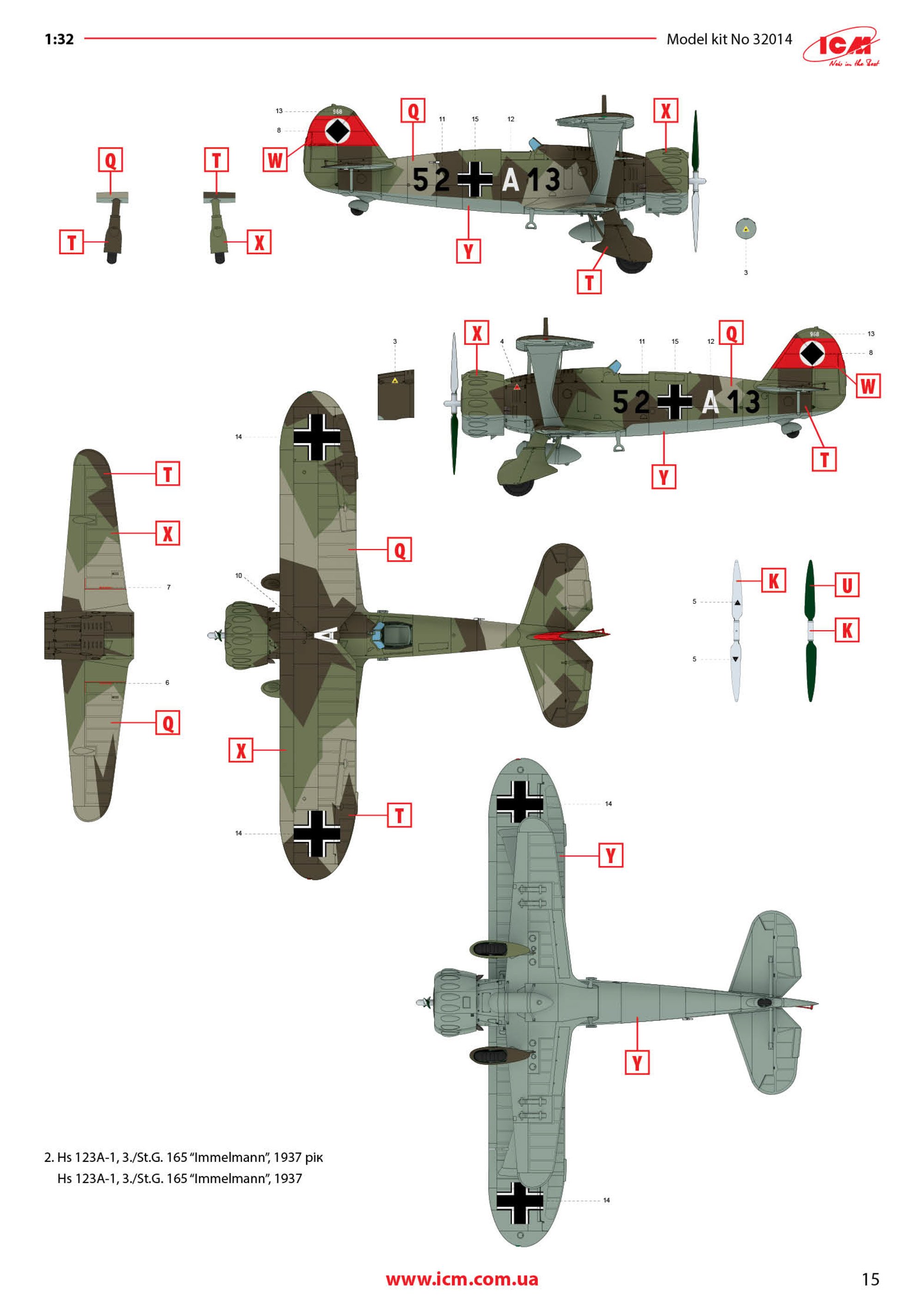
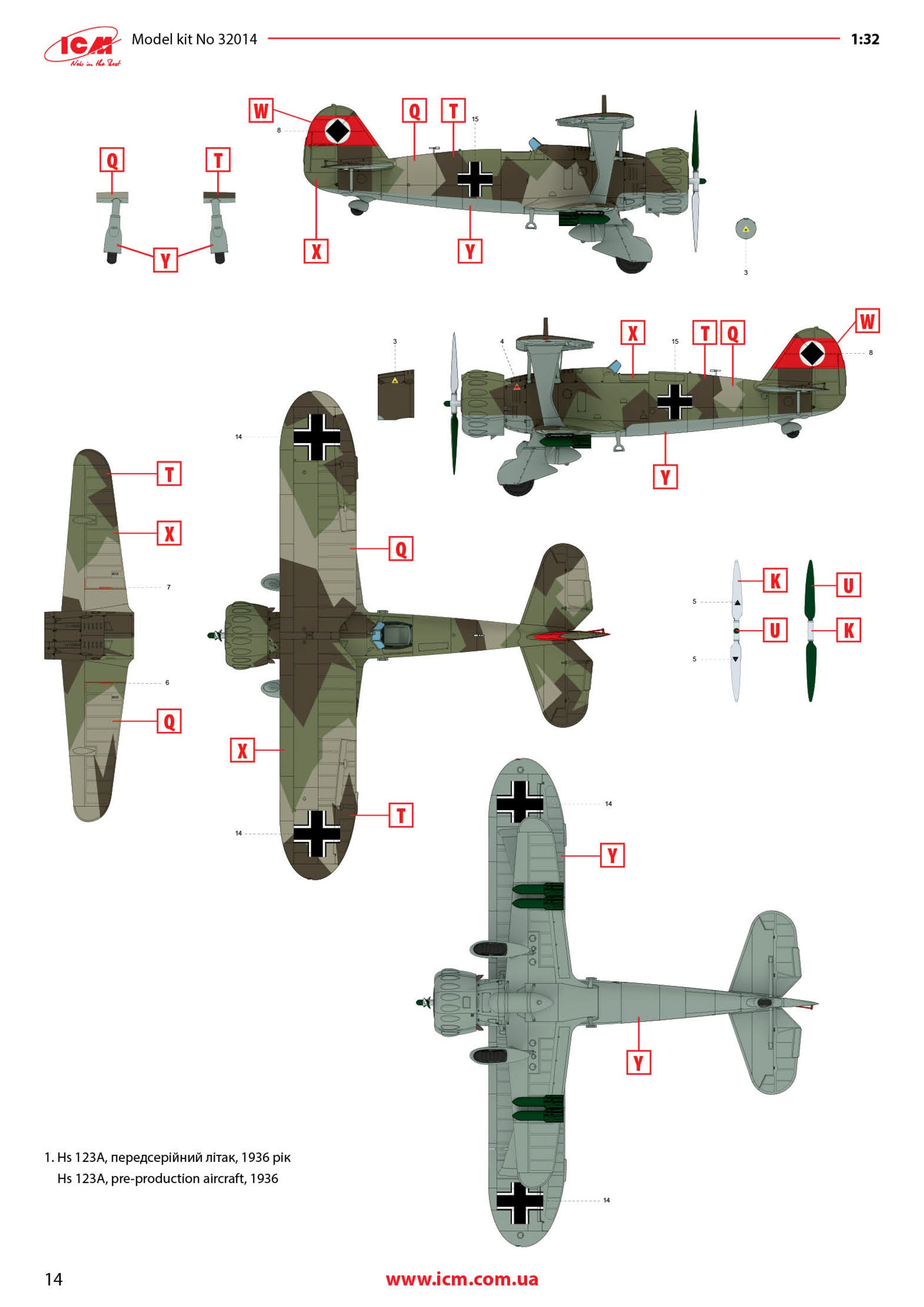
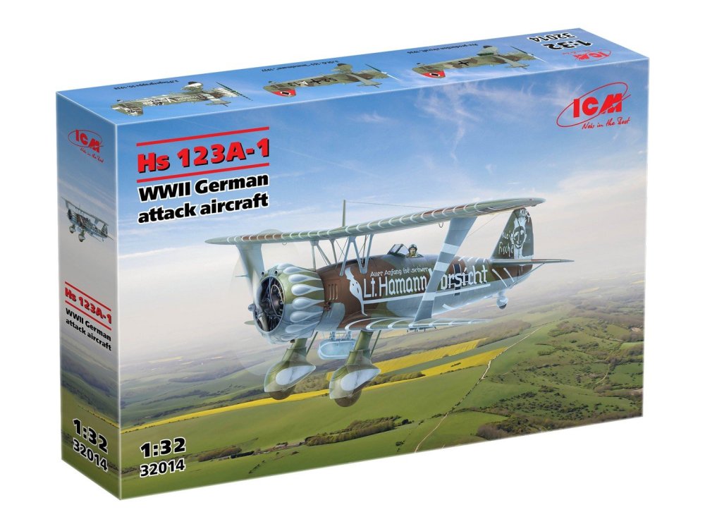
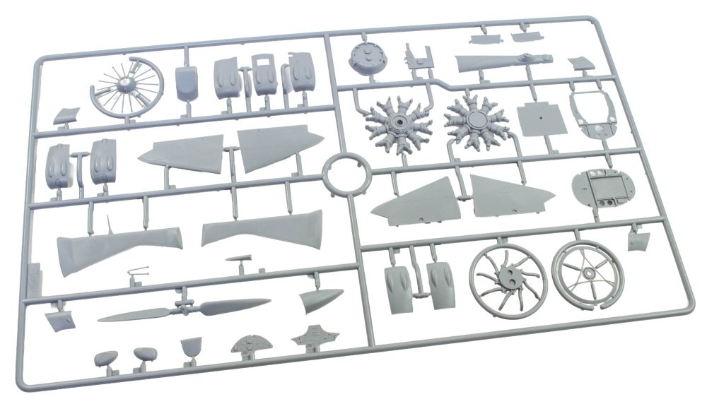
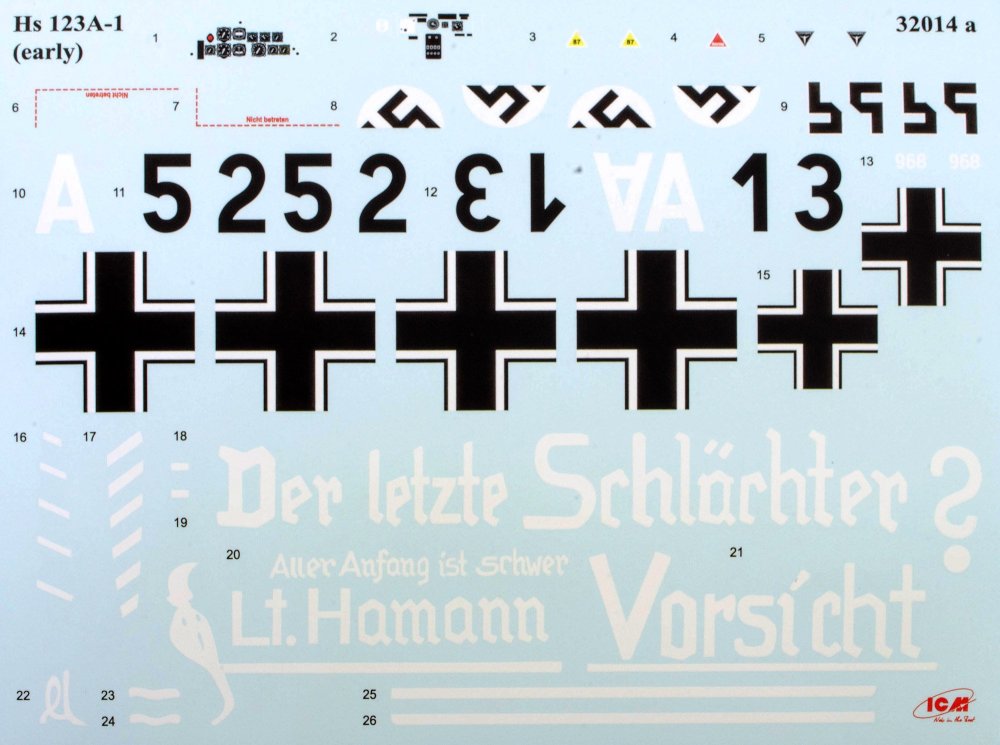
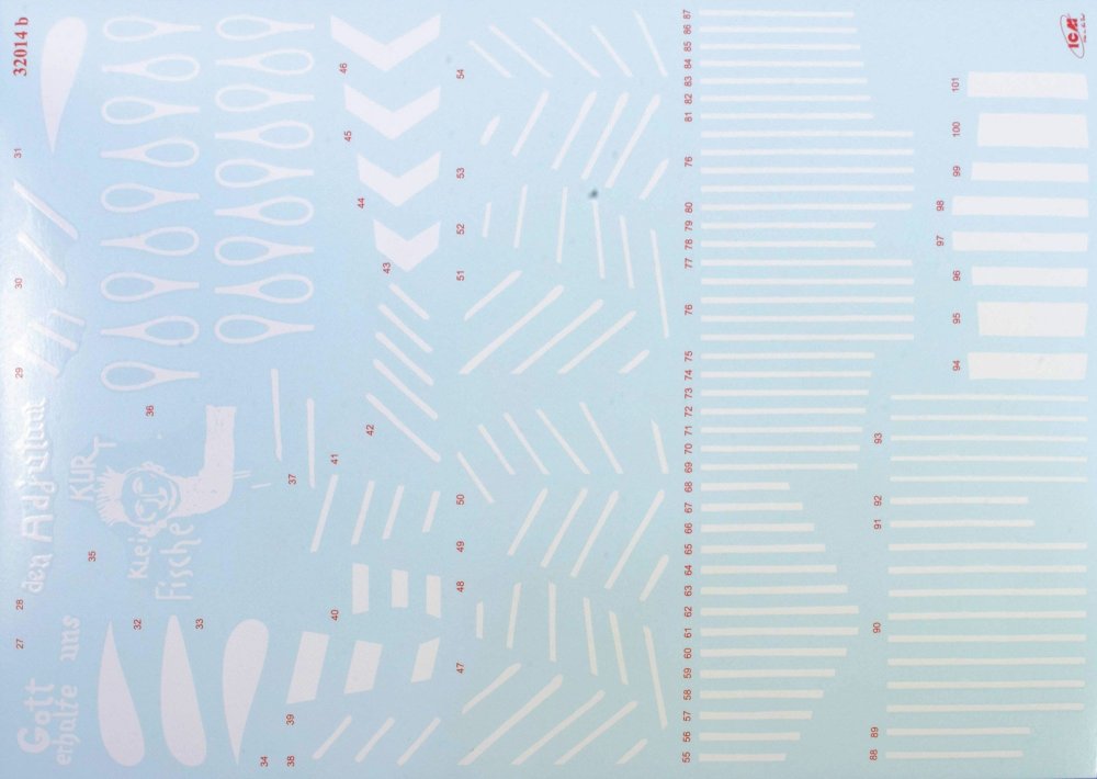
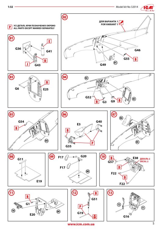
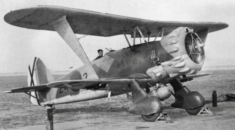
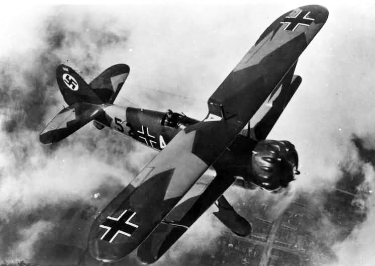
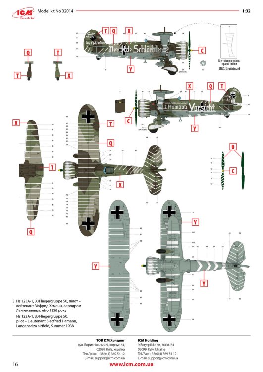
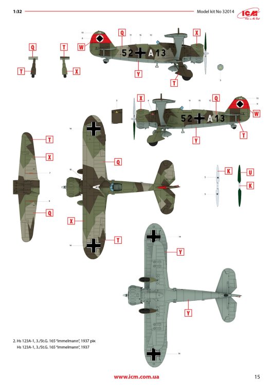
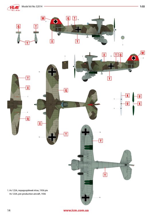
1:48 Hs 123A-1 ICM Catalogue # 32016 Available from Jadlam for £47.49 The Henschel Hs 123A-1 was a German single-seat biplane dive bomber and ground-attack aircraft developed in the early 1930s, during a period when the Luftwaffe was still in its formative stages. Designed by Henschel Flugzeug-Werke, the Hs 123 first flew in April 1935 and was initially intended to serve as a modern dive bomber for Germany’s rapidly expanding air force. At the time, biplane designs were becoming outdated, but the Hs 123 stood out for its strong construction, excellent manoeuvrability, and reliability. The A-1 variant was the first production model and entered service in 1936, helping to establish Germany’s early close air support and tactical bombing capabilities. The Hs 123A-1 saw its first combat use during the Spanish Civil War (1936–1939), where it was flown by the German Condor Legion in support of Nationalist forces. In this conflict, the aircraft proved highly effective in ground-attack missions, using bombs and machine guns to strike enemy troops, vehicles, and fortifications. Pilots praised its ruggedness and ability to operate from rough airfields close to the front lines. The aircraft’s radial engine produced a distinctive sound in dives that was designed to intimidate enemy troops, adding to its psychological impact. Experiences in Spain demonstrated that, despite its outdated appearance, the Hs 123A-1 was well suited to low-altitude battlefield support. During the early years of World War II, the Hs 123A-1 continued to serve with the Luftwaffe in campaigns in Poland, France, and on the Eastern Front. Although more modern monoplanes were becoming standard, the Hs 123 remained in use because of its durability and effectiveness in harsh conditions. It was especially valued in the Soviet Union, where it could operate from primitive airstrips and withstand heavy ground fire. By 1942, most Hs 123 aircraft had been replaced by newer designs such as the Junkers Ju 87, but some remained in frontline service until 1944. The Hs 123A-1 is remembered as one of the last successful combat biplanes and as an important contributor to early German close air support doctrine. The kit This kit is ICM's fourth incarnation of the Henschel Hs 123 kit, since its inception in 2024. For me, this probably has the most bizarre but extremely attractive scheme that ever adorned this type. The kit itself is packaged into one of ICM's very sturdy top flap opening boxes, with a separate glossy lid depicting that particular machine that I mentioned. Inside, there are EIGHT sprues in grey styrene, and one in clear. There is also a 16 page, full colour instruction booklet, and TWO decal sheets. Ok, let's take a peek... Not too many parts on this sprue, but we do start with a view of the fuselage halves. The kit is moulded in ICM's usual mid/light grey styrene which melts beautifully with a decent cement like Tamiya's hot stuff. The fuselage is typical of ICM in that there's no rivet detail, but the panel lines are nicely represented with some finesse. If you want rivets, then it's time to put Rosie to use. You could, I suppose open the louvres up a little, but I'm not convinced that it would be necessary as the gap would be tiny. Some wash in there would probably have the same effect. Internally, the fuse has some moulded detail onto which to add further detail. One particular machine will need hole(s) drilling out, clearly shown in the manual. Also supplied here is the forward upper fuse with integral MG channels, and a two-part drop tank that will be slung underneath he fuse centreline. Three parts comprise the lower wing, with the underside being full span (yet relatively small in 1:32). Again, no rivet detail, but pretty much everything else. The landing flaps are moulded in a closed position. The lower wing doesn't have ailerons, so no need for such details. The strut sockets are reasonably deep too, meaning fitting and mounting the upper wing should be quite easy. All parts here are used except for two upper wing inserts which would be used to hang the ailerons. There is a set to use here, so not quite sure what the difference is except for a possibly different aileron style. Here you will fine the aileron, elevator and rudder halves. all with excellent fabric and rib details...not too harsh to my eye. There are TWO of these sprues, duplicating all of the parts of which there are two or more. Here you will find undercarriage struts, spats, ordnance (plus percussion bombs), wheels, bomb racks, fuselage MGs, etc. Everything on this sprue is to be used with this release. This is where you'll find many of the cockpit details, as well as two-part intake unit, cabana struts, tailplane support struts (moulded as a single part), engine exhaust array, and things such as control surface push/pull rods. Now we can see the various parts which construct the BMW 132D radial engine, These are moulded in beautiful detail, and with some quite fragile parts that could use some decent quality nippers to remove from the sprue. You will also see the multipart engine cowl with its familiar blisters, wing struts, tailplane halves, two-blade prop, cockpit bulkheads, seat, and instrument panel etc. The entire upper wing is moulded in two full-span parts, minus the ailerons. The detail nicely represents the fabric covered original with its dope-shrunk scalloped surface. There is only one clear sprue, and it's tiny. This comprises the windscreen and wingtip lights. You can't see in this photo, but the clarity of the parts is every bit as good as other contemporary manufacturers. Decals The are TWO decal sheets in this release, catering to THREE different schemes. One sheet carries decals for just one single machine, meaning all those whacky white lines and graffiti don't have to be done by hand or masked. All decals are thinly printed and in perfect register, with minimal carrier film. Colour is solid, which is just as well with all the white coloured decals to add to a Spanish splinter style scheme. The three schemes supplied are: Hs 123A, pre-production aircraft, 1936 Hs 123A-1, 3./St.G. 165 "Immelmann", 1937 Hs 123A-1, 3./Fliegergruppe 50, Lieutenant Siegfried Hamann, Langensalza airfield, Summer 1938 Instructions A full colour, 16-page manual is included, complete with parts maps and multiple elevations for each scheme. Construction is shown in clear line drawing format, with good paint notation given for ICM's own paint range. Conclusion ICM did a great job of recreating this aircraft in 1:32 and really has done it some justice. Moulding is excellent with zero flash and ejector pin marks aren't of any issue here. So much detail is to be had, and for those wanting more than regular Luftwaffe splinter camo, this has it all...from a simple looking machine to possibly the most incredibly unique machine of them all; that of Lieutenant Siegfried Hamann. Go ahead and treat yourself! My sincere thanks to ICM for sending this kit out for review on Large Scale Modeller. To buy direct, click the link at the to pop the article.


-
Yup, that's why I said it. In fact, I've been out of the hobby for 6yrs now. Much has changed.
-
It IS a subject that interests me, but paying a lot of money up front for something at least 2yrs away....nope. It's actually a Mk.V I would love to have but I still don't think I'd be paying for what is a kickstarter.
-
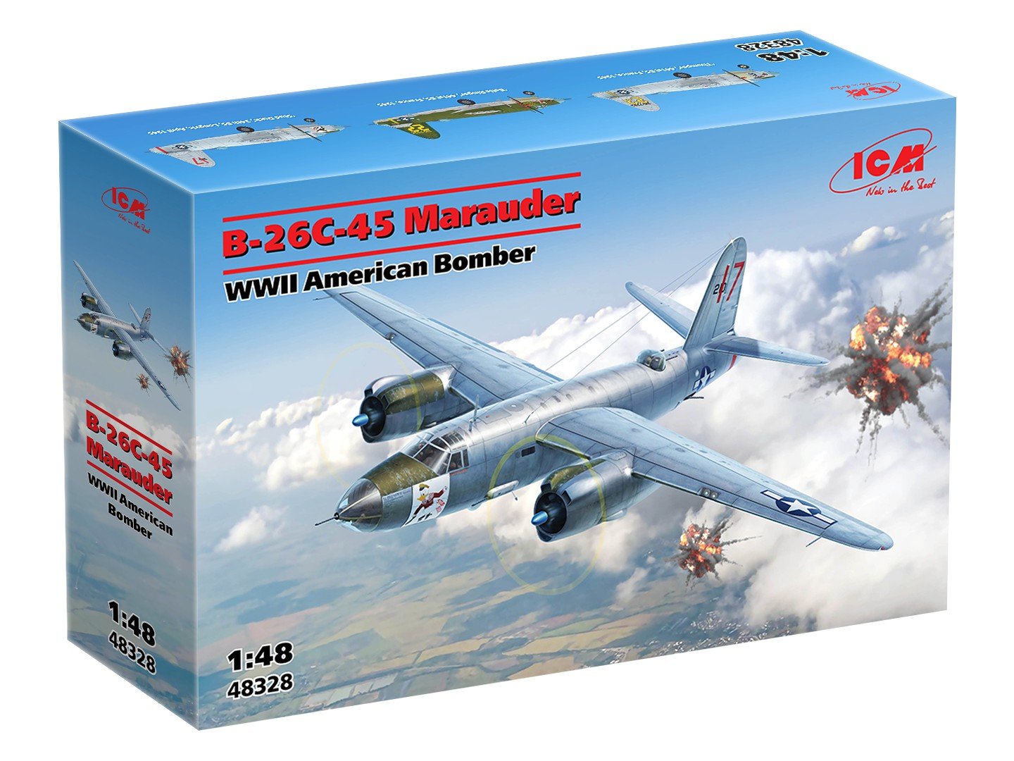
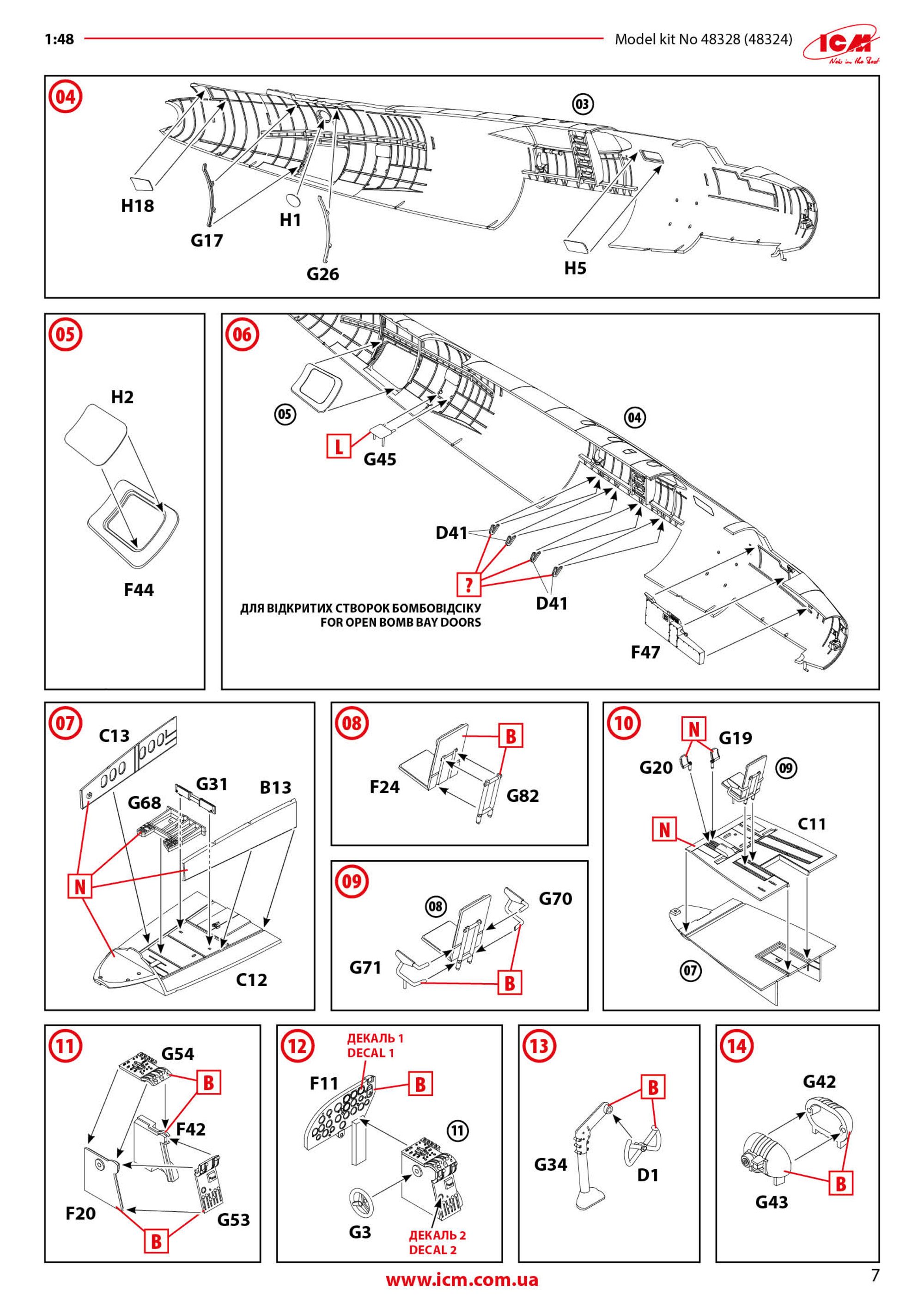
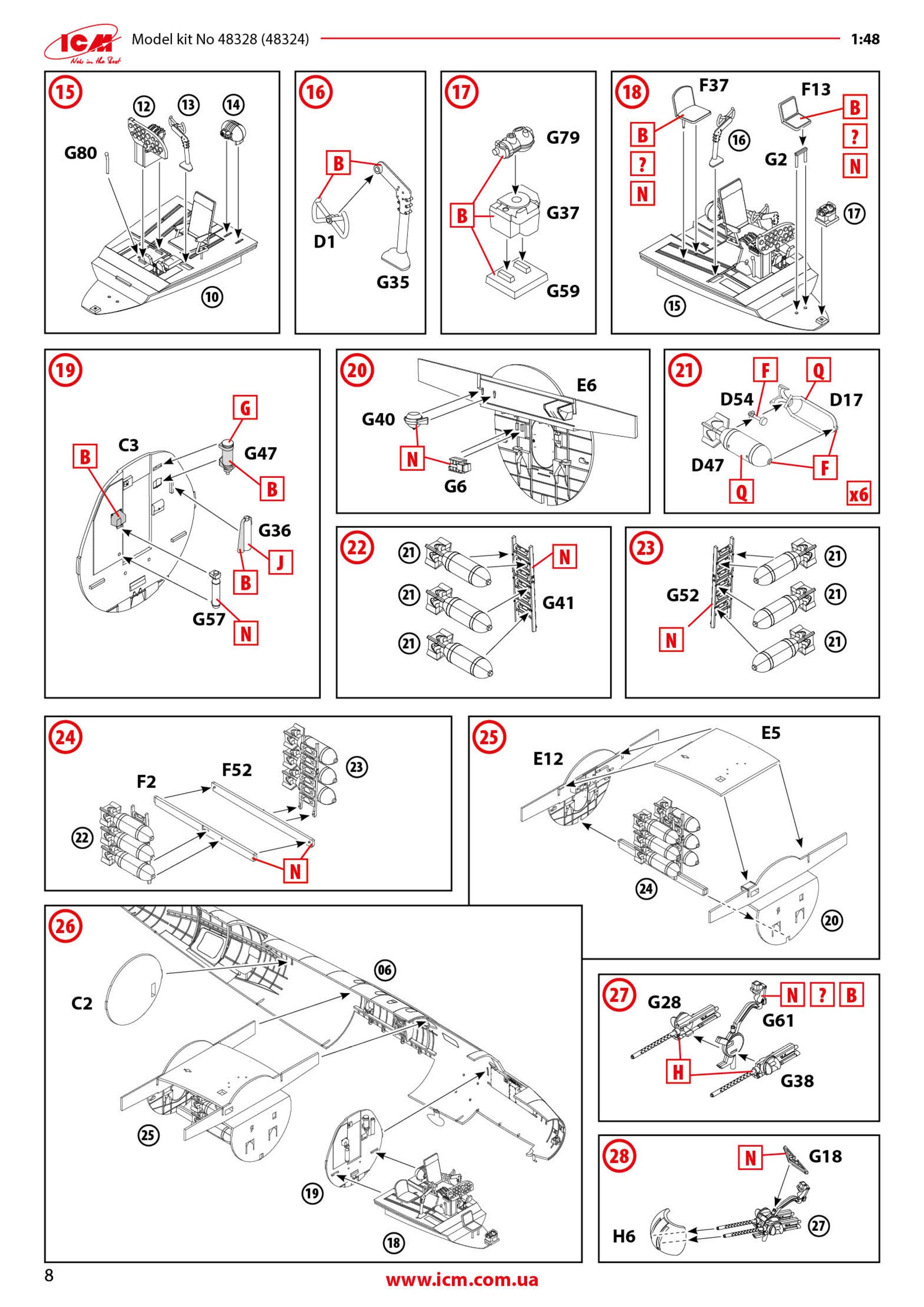
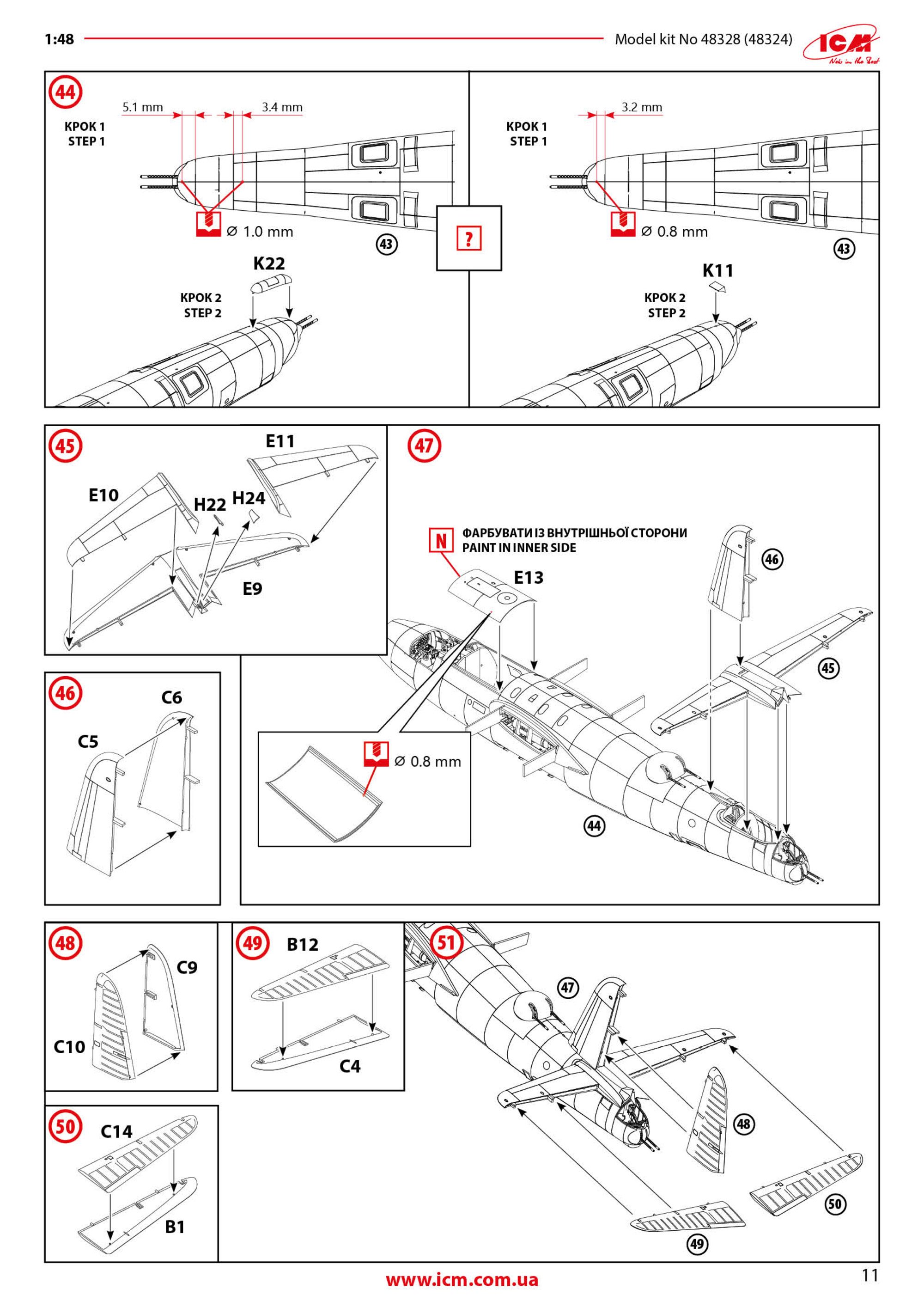
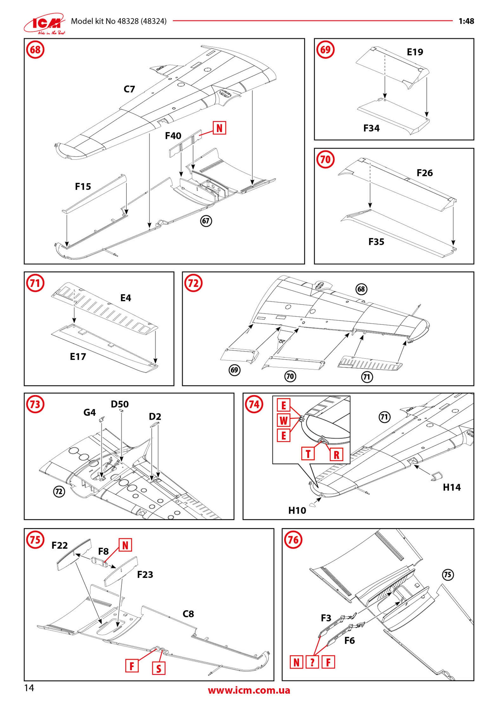
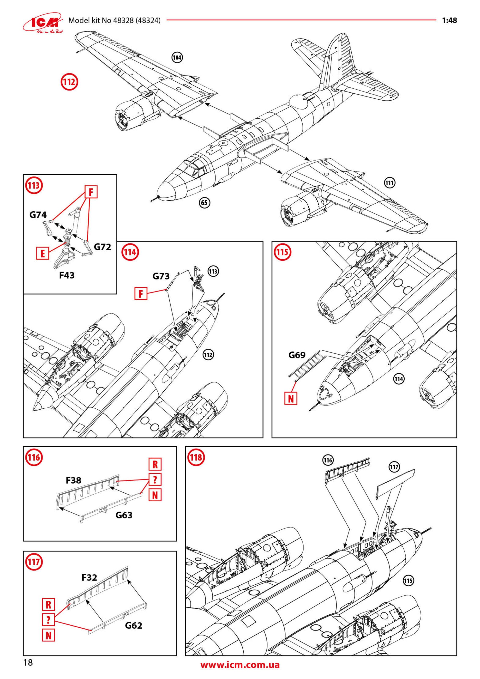
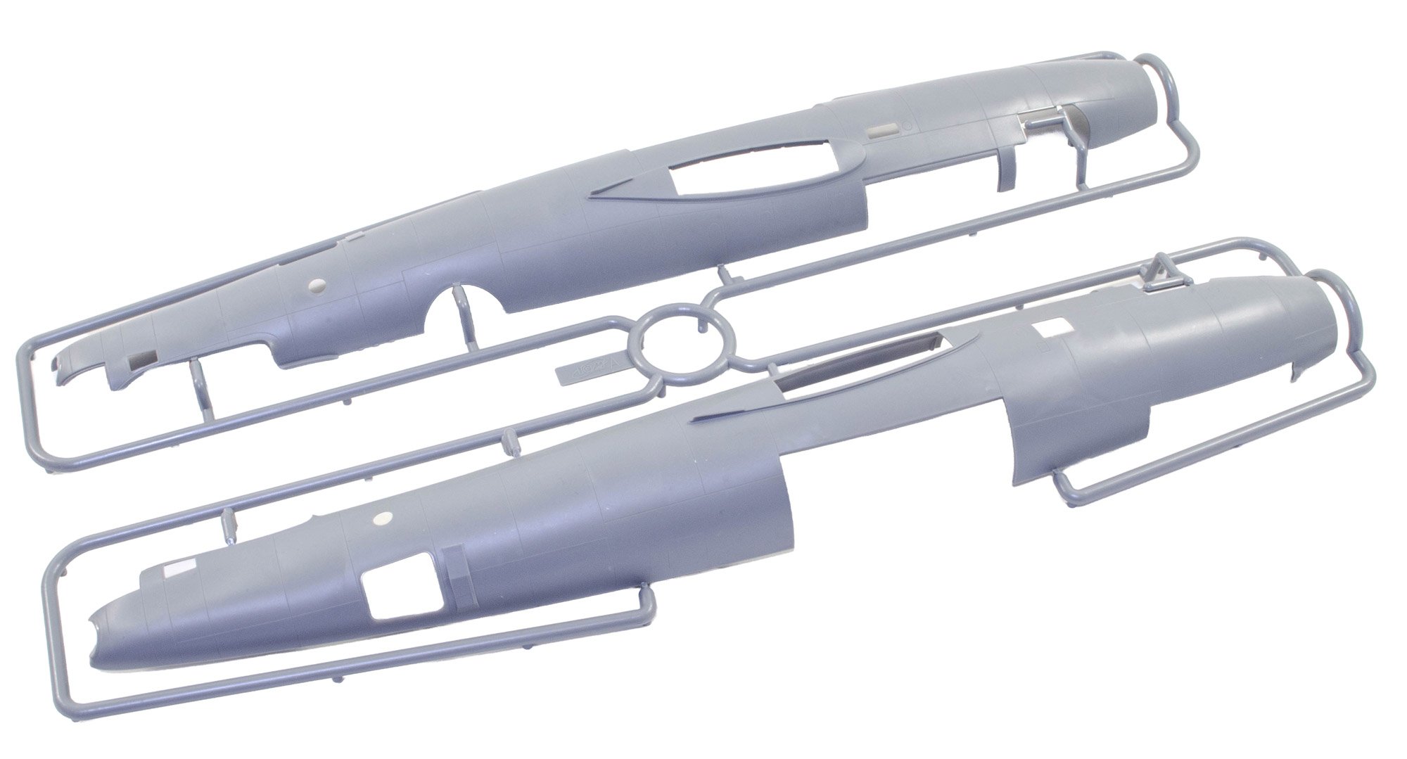
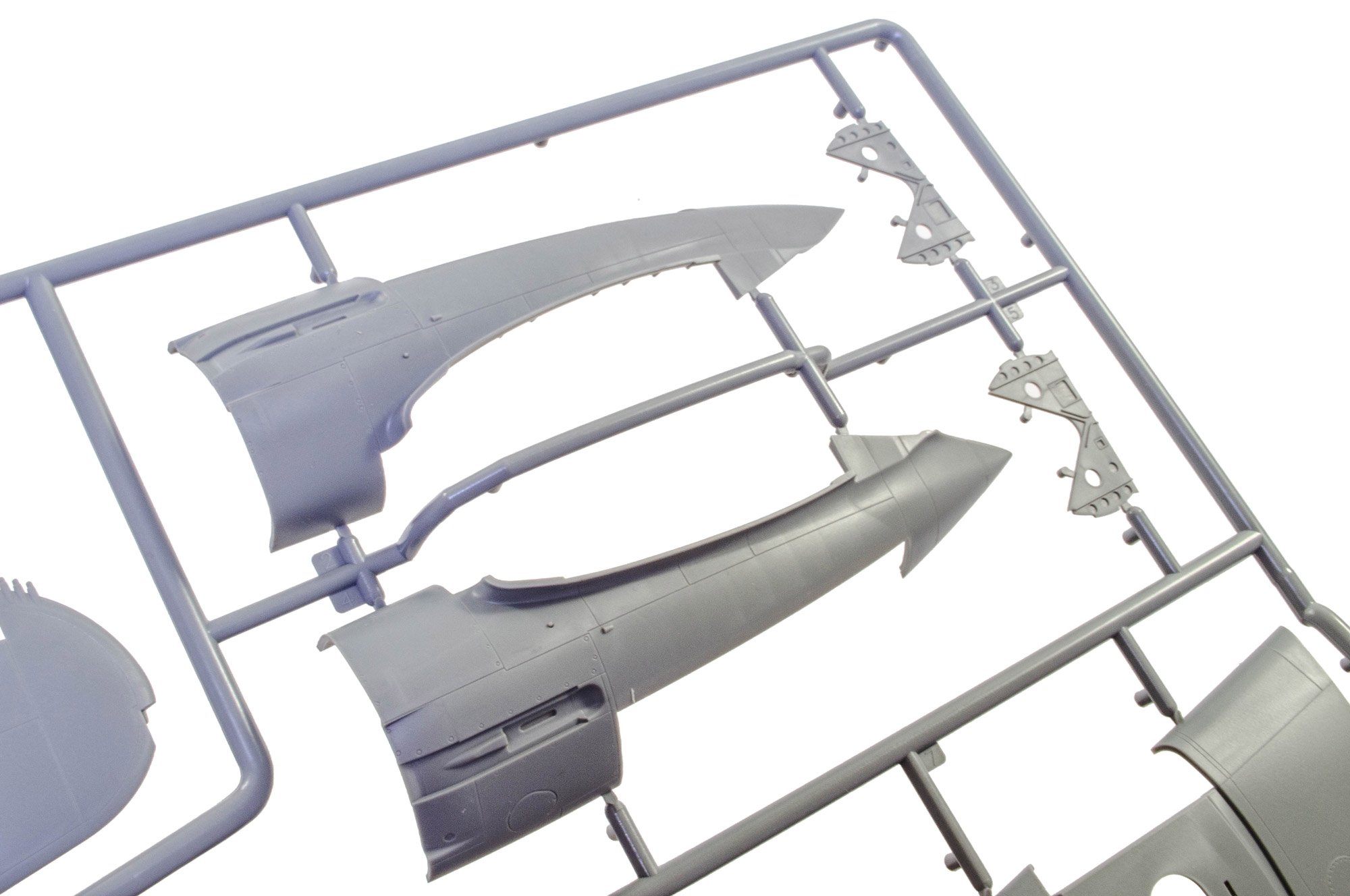
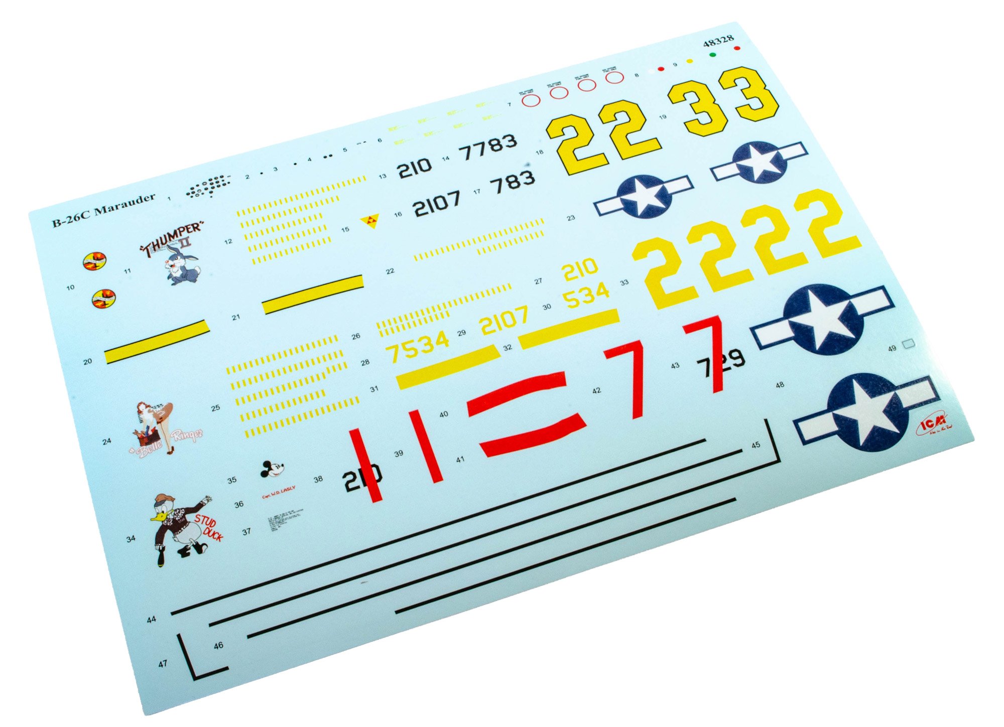
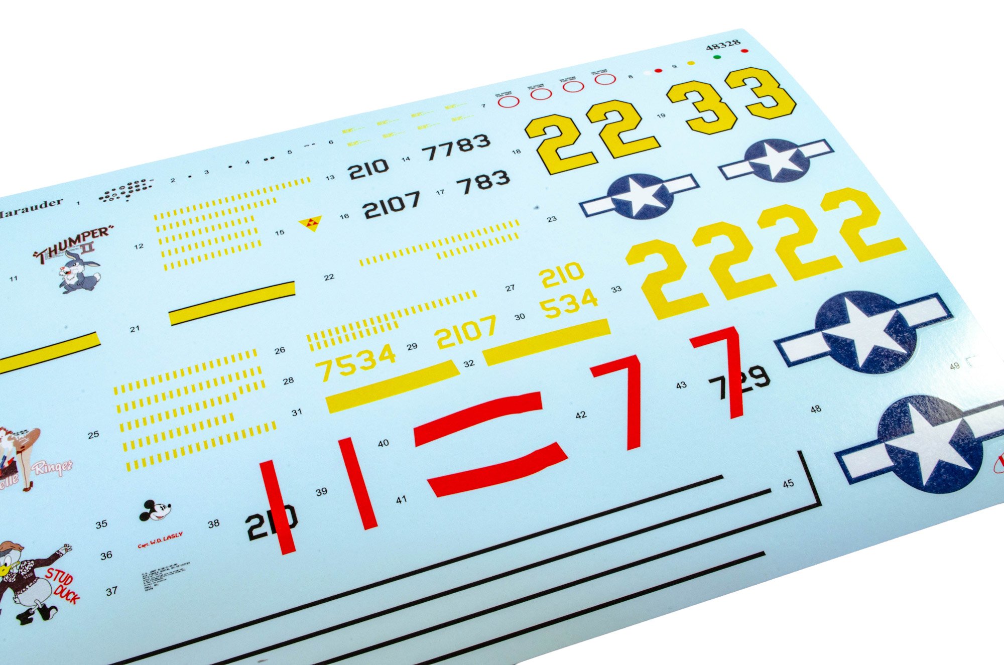
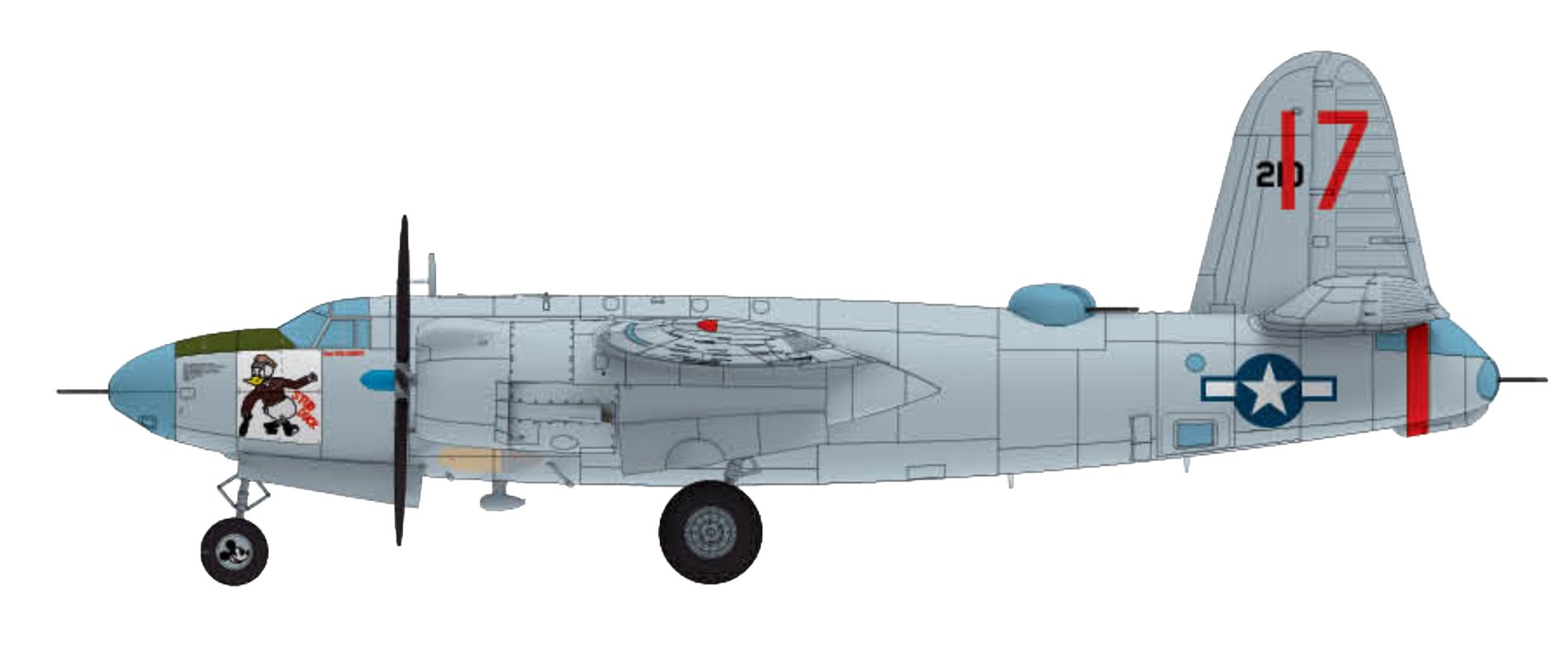
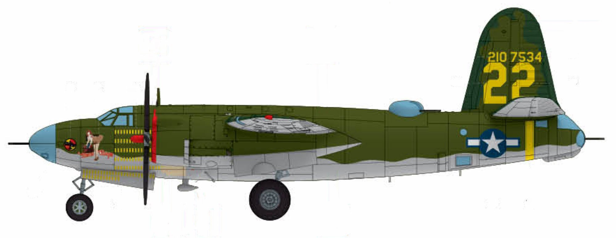
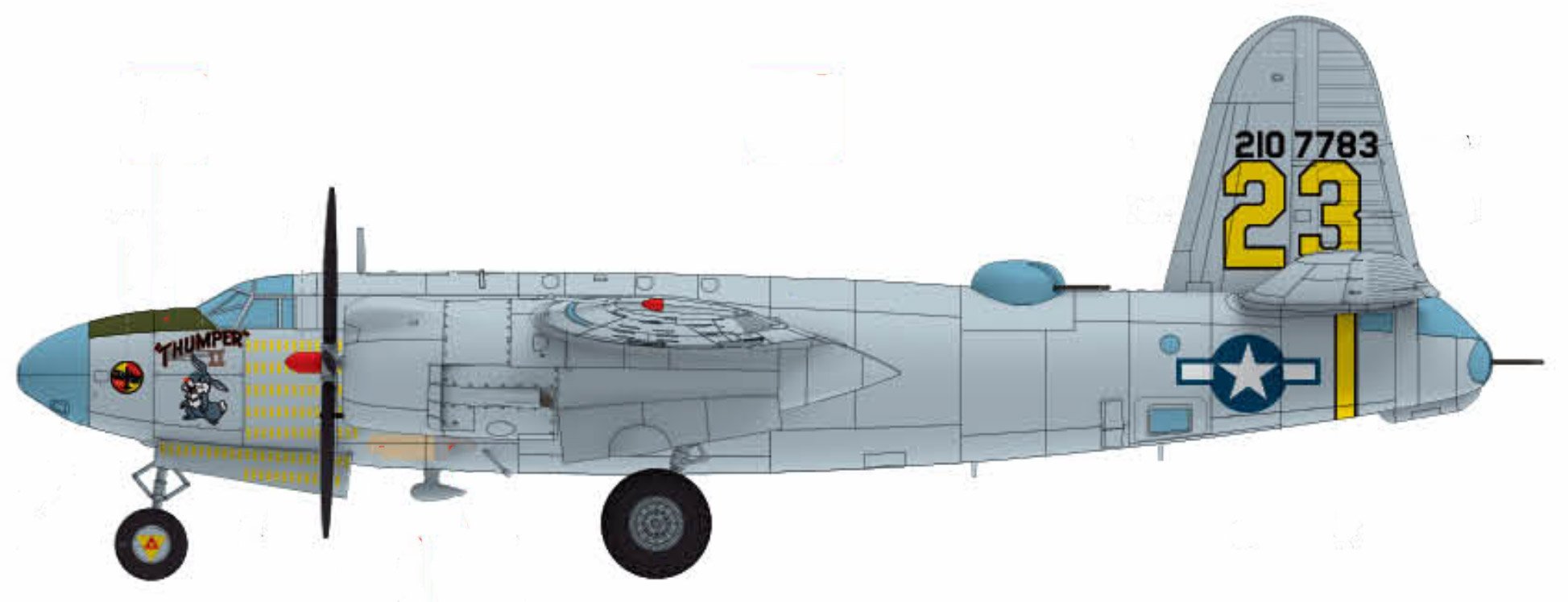
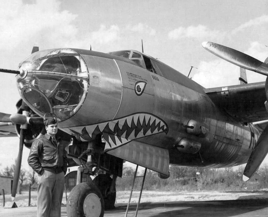
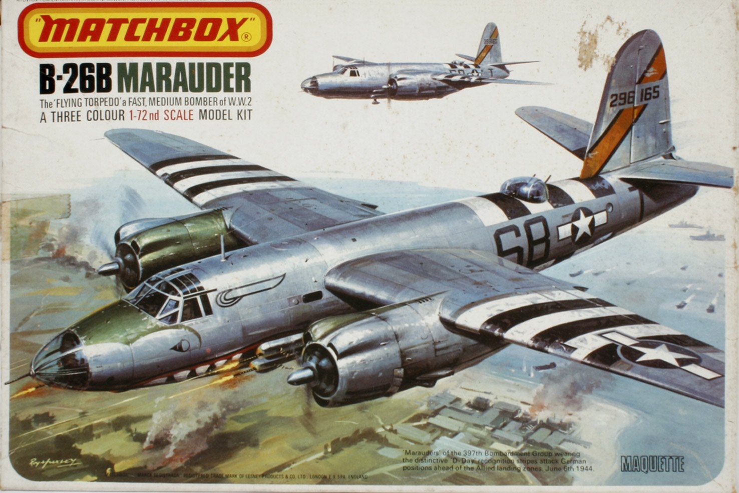
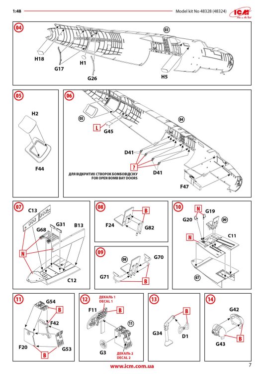
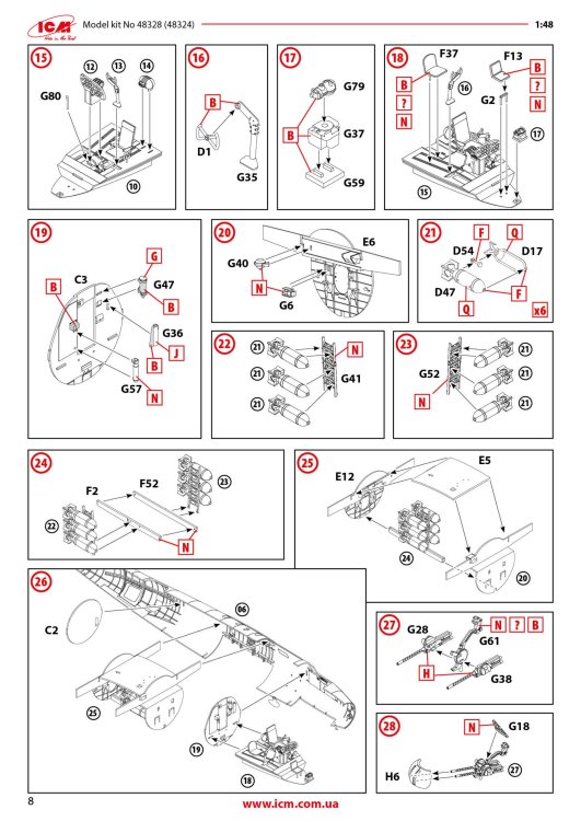
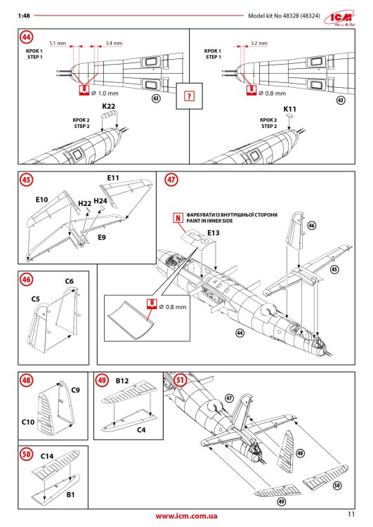
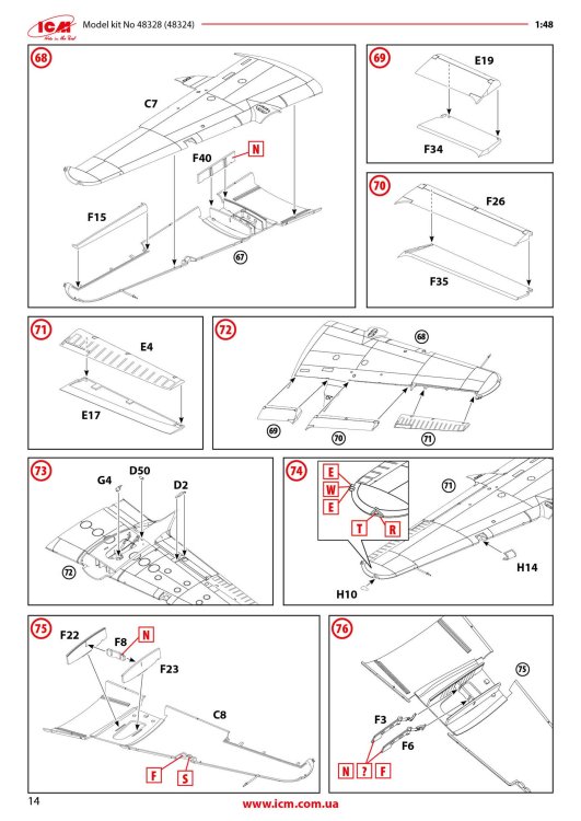
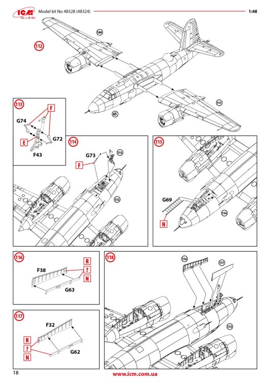
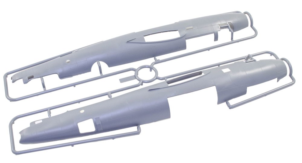
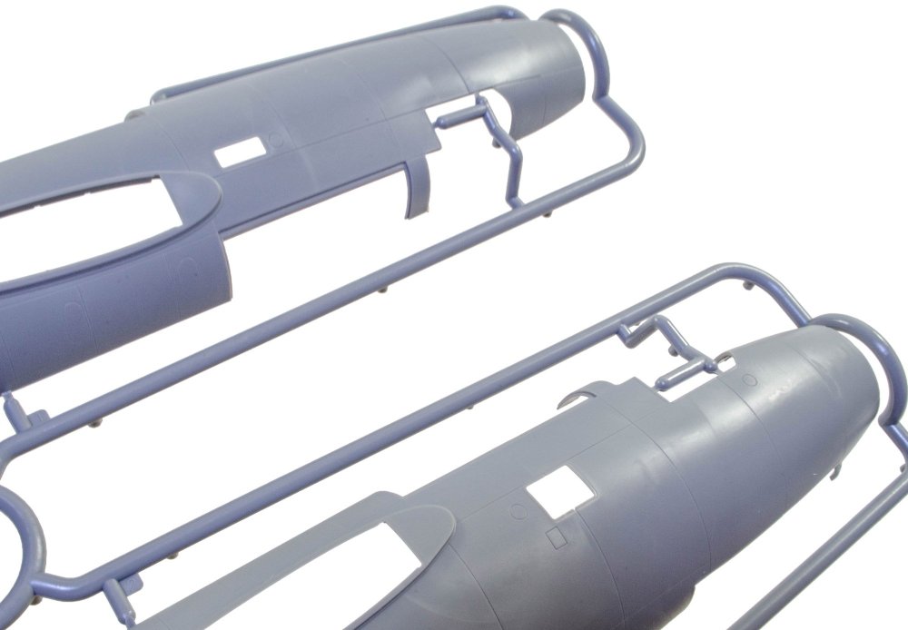
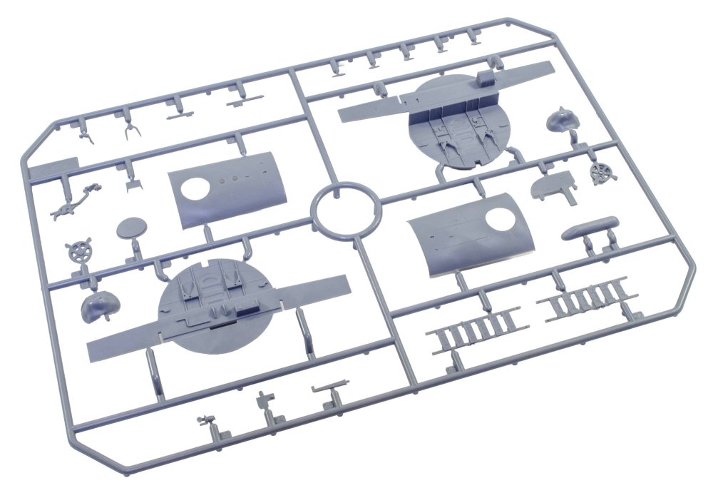
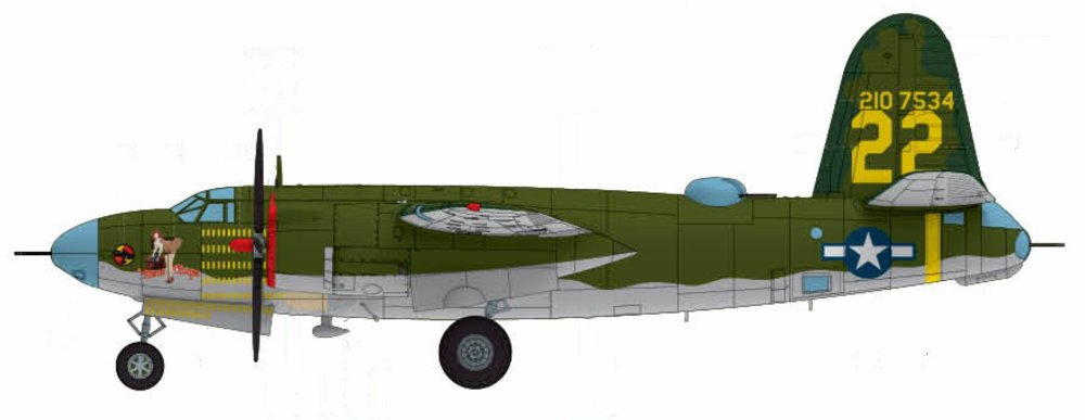
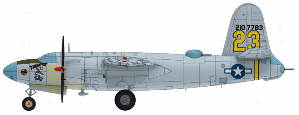
1:48 B-26C-45 Marauder ICM Catalogue # 48328 Available from Scale Model Shop for £67.49 The Martin B-26 Marauder was an American twin-engine medium bomber developed in the late 1930s and early 1940s for the U.S. Army Air Corps. First flying in 1940, it was designed for high speed and efficiency, featuring a sleek, narrow wing and powerful engines. These features made it one of the fastest bombers of its time, but they also resulted in demanding flight characteristics, especially during take-off and landing. Early in its service, a high accident rate earned it the nickname “Widowmaker,” raising concerns among pilots and commanders. As World War II progressed, improvements in pilot training and aircraft design greatly reduced accidents. The B-26 was deployed widely in Europe, North Africa, and the Pacific, with its most significant impact in the European Theatre. There, it was used primarily by the Ninth Air Force for medium-altitude bombing missions against German transportation networks, airfields, and military installations. Its speed, durability, and ability to carry a substantial bomb load made it an effective tactical bomber once crews mastered its handling. By the later years of the war, the B-26 had earned a strong reputation for reliability and survivability. It achieved one of the lowest loss rates of any American bomber in combat, thanks to its rugged construction and disciplined operational use. After World War II, the Marauder was quickly retired from frontline service as newer aircraft became available. Nevertheless, it remains remembered as a plane that overcame early difficulties to become one of the most successful medium bombers of the war. The kit This is around the 9th or 10th incarnation of the ICM B-26 Marauder kit since its initial release in 2024…and remember we are only just into February of 2026. This time we see the B-26C-45 (Block 45) The B-26C-45 Marauder was a specific production block of the Martin B-26C; the Omaha-built counterpart to the Baltimore-built B-26B series. The Block 45 possessed larger wings and tail, refined defensive armament and sights, stronger bomb gear and standardised late-production fittings. The kit itself is packaged into ICM’s standard and very robust corrugated box with a top opening flap, and a thinner, glossy and separate product lid. Inside the box, we are met with a number of thick cellophane sleeves that contain NINE sprues of light grey styrene and ONE clear sprue. The size of the model is hinted at with the main fuselage halves. Like all/most ICM kits, the exterior doesn't contain rivets but is plenty rich in just about all other detail. The finish of these large parts is excellent. Internally, you can see stringer and former detail that will adorn the crew areas. You can see here that the wings aren't just simple tab and slot connections. There are two bulkheads which flank the bomb bay and these have the mini spar sections onto which the completed wings will slide. The tail unit sits atop of the rear fuselage and again, aren't just surfaces which plug into the fuse. There are some holes that will need drilling out of these parts, specific to this version. The manual clearly illustrates these. You can see some bomb bay bulkheads in this sprue, BUT, these aren't used in this build. Instead, we have alternative parts which you'll see soon. In fact, there are only eight parts that will be used off this sprue, and they aren't any of the larger ones either. Most of this sprue is redundant. On these two sprues, you will find many common parts for which there are duplicates, such as props, engine parts, ordnance, weapons, optional cheek gun pods (fitted to one machine), cowl parts, u/c door hinge units, and main gear bay doors. Absolutely lots of finesse in the moulding here. No flash or awkward elector pin marks. Another detail sprue. There's only one single part not being used here, showing you the sheer level of detail and number of parts that will go into your final build. ICM state this version of the Marauder contains 362 parts, accounting for the optional gun pods on one machine. Parts on this sprue include cockpit and bulkhead details, bomb rack ladders, armaments, bomb bay door actuators (if posing the doors open), gear scissors, cockpit access ladder, etc. All parts here are slated for use. Here you will find more cockpit elements, parts for the split landing flaps, crew area and ammunition feed detail, wall mounted bomb racks, turret details, u/c gear bay parts, etc. The most obvious parts here need no explanation. The wings are simply fitted out with their internals for the gear bays and then the halves can be glued together before things like ailerons, flaps and nacelles are added. Other sprue it4ms include bulkheads, turret mounting plate and both sections of the forward cockpit floor. Here are the bomb bay fore and aft bulkheads with their associated wing spar detail onto which the main wings will mount, as well as the single piece upper tail section with their set dihedral, as well as the lower panels, supplied as individual parts. There is more split flap detail here, and crew floor sections for the various areas such as the tail gunner, and also the ceiling for the bomb bay. This sprue almost mirrors the previous one containing the wing sections. On here though, you will find parts for the internal nacelle gear bays as well as the nacelles themselves which are moulded as halves. A single clear sprue is included, protected by a foam wrap and separately sealed. The clarity of these parts is excellent. Both of the main cockpit windshields are for use with this release, depending on which machine you build. One of them has more framing than the other. Only one of the glazed nose parts can be used though, common to all three machines offered in this release. Decals A single decal sheet is included, with markings for THREE machines. These also include walkway lines and a small number of stencils, as well as some cockpit decals. I'm unsure of who prints these, and they could of course be done in-house. These glossy decals have solid colour, perfect registration and minimal carrier film. There is a similarity to the HGW decals here in that when the decal is applied, the 'carrier film' can be carefully removed from the model, leaving just the ink in place on your project. You can then seal that as normal before weathering. The three schemes are: 1. B-26C-45-MO 42-107783, Thumper, 441st Bombardment Squadron, 320th Bombardment Group, France, 1945 2. B-26C-45-MO 42-107534 Belle Ringer, 441st Bombardment Squadron, 320th Bombardment Group, France, 1945 3. B-26C-45-MO 42-107729 Stud Duck, 34th Bombardment Squadron, 17th Bombardment Group France, Longvic, April 1945 Instructions A full-colour 24 page instruction manual is included, detailing every step is clear line drawing format, including images of parts maps for you to check against construction. Where options are presented in construction, those notes are clear and unambiguous. Full colour illustration is supplied for all three schemes. A set of mask templates are also printed so you may use them for making your own masks, although it would be nice to have masks included as standard. Conclusion My first encounter with the Marauder was back in around 1982 when I built the 1:72 Matchbox kit. There was just something about the shape of the bomber that gave it real presence. I saved my pocket money up for about 3 weeks to buy it. This is the first time I've seen this in 1:48 (yes, I'm a little late to the ICM Marauder party!), and I am absolutely thrilled to see what this Ukrainian company have done with this legendary aircraft. This has all the hallmarks of a potential masterpiece. I've done some trawling of builds of the earlier ICM releases and there certainly doesn't appear to be any areas of concern. Simply put, an amazing release which I hope to see some builds for here on LSM. VERY highly recommended! My sincere thanks to the good folk at ICM for sending out this sample for review on Large Scale Modeller. To buy, click the link at the top of the article.


-
So this is essentially a 'kickstarter' project? 2028, seriously? I'm out.
-
FAQ 2 - Aircraft Scale Modeling By Daniel Zamarbide
JayDee replied to Fran's topic in Tools, Books & Misc.
I should get one as I need to re-learn. -
This looks like a carbon copy of my work, with that styrene rod section too. I also had a lot of shrinkage in the outer shells and had to add card to it to make it all fit.
-
5 Cylinder Radial Engine (TECHING) - EngineDIY
JayDee replied to JayDee's topic in LSM-Related Reviews (military figures etc)
Oh, and if anyone wants one, I have a code that I'm told will give 16% off. -
5 Cylinder Radial Engine (TECHING) - EngineDIY
JayDee replied to JayDee's topic in LSM-Related Reviews (military figures etc)
Here is the main event! The model is actually quite large and weighty, and we haven't finished yet. The ejector rods and sleeves are now to be fitted. This is done one cylinder at a time, and needs to the rocker arms to be lifted to allow the ejector rods to sit. The base is now fitted, and a spacer mounted between the base and engine. Once fitted, the battery charger port, switch and motor cables are threaded into the base. The cables are then plugged into a control board, along with a battery pack. The circuit is then screwed into the base and a cover fitted to hide it all. The kit also includes a USB charging cable too (not shown). COMPLETE! And here is a video I made of my review build. The instruction manual is clearly illustrated and the average builder should find zero difficulty in following each stage. Conclusion I didn't know what to expect before seeing this kit in the flesh, and I was very pleasantly surprised. I'd had a hankering for building something like this for a while, but I suspect the mixed reviews I'd seen were from cheap copies. This kit very much surpasses my expectations in presentation, quality, and also the final result. This model took me about 5hrs to complete, but that's also because I was setting up photos of each stage. I think it's fair to say that the manufacturer expectation of about 3hrs is reasonably accurate. The instructions are very easy to follow and should present no problems, even to a beginner who has no sort of modelling or engineering experience. All parts fit perfectly together with no issue. The only things I would criticise are the hex keys which are a little soft and round off easily, making tightening the screws hard. Also, there is no lube in this kit any longer, so you will need to source your own. In all, a fantastic kit. My sincere thanks to EngineDIY for sending out this kit for review on Large Scale Modeller. I'm more than sure you'd really enjoy this one. To buy direct, click the link in the header of this topic. -
5 Cylinder Radial Engine (TECHING) - EngineDIY
JayDee replied to JayDee's topic in LSM-Related Reviews (military figures etc)
If you see any black flecks as are visible here, these are just some debris from the foam trays. Parts with this are just blown clear before assembly. Here are the cam and gear which are simply fastened with four small screws. The cam drive gears are now selected and assembled as shown. You'll notice the mounting pins are machined to accept the gears. The gears must also be fitted in the orientation shown in the manual. Yes, you see that correctly....a metallic red prop! Whilst I understand that it's better to include a machined metal prop as there won't be any balance issues, I might well have selected a different colour to anodise it. Still, this is a display model and it does looks strangely attractive when fitted. Here you see the prop and the front crankcase with the bearing, collar and prop hub parts. Now it's onto the rocker arm assemblies. It's here you'll find the only plastic parts of the engine, seen here in black. The quality is still excellent and these parts aren't at all fragile. We turn our attention to the five cylinder head assemblies. Lots of screws to use here and you can see the exhaust ports and valves here. The valves do actually work too. The rocker arms are now fitted to the top of the valve assemblies, and little reproduction spark plugs added. You could choose to paint the insulators in white, but I opted to leave in natural metal. The cylinder blocks themselves are now fitted to the completed cylinder heads. -
5 Cylinder Radial Engine (TECHING) - EngineDIY
JayDee replied to JayDee's topic in LSM-Related Reviews (military figures etc)
The lack of lube in the kit meant that I needed to buy some. I opted for this stuff, and used cotton buds to apply to the various connections. The manual us very clear about where lube is to be added, and this generally centres around the pistons and crankcase...not inside the piston heads. Piston assembly is very easy. All you need to do is to sit the linkages into the piston head and then insert a pin which is then locked into place by two circlips. As with the real engine, one of these has a master rod which connects to the crankshaft and does NOT articulate. Here, that is the second from the left. You can see a section machined out of the base which then is pinned to the crankshaft. The others will articulate. The crankshaft now sits within the crankcase. I add a little lube to this. This part is then added to the crankshaft and provides the base onto which the pistons will fit. This is supplied with a small bearing that neatly pushes into it before assembly. The pins you see are for locating the pistons into the recesses in the assembly. There is one task in assembling this engine, that could drive you to distraction, and that's adding the pistons. Without a doubt, this is awkward as there are five of these which will persistently try to fall out as you add the next. The best way to do this is to sit the crankcase into one of the cutouts in the foam parts tray and then carefully prop up each of the piston heads so they don't fall away from the centre of the crankcase. When you have them all in position, you can then add the linkage cap and screw it into position. This stage feels like a real achievement. This crank can now be fitted into place. This is a working model, so a little cheat needs to be fitted, in the shape of an electric motor which will drive the gearing. This is also very nicely hidden when complete. The completed rear crankcase now now be screwed to the main casing. One thing the manual does not make clear is that the motor needs to be adjacent to the stand connection on the main crankcase. I did fathom that out, but I have seen at least one video where a builder has a wire stretched around the back of the crankcase, down to the stand which contains the battery. The motor is then covered over.