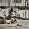
krow113 Posted January 1, 2014 Posted January 1, 2014 Seeing the excellent tutorials going on here I noticed a request for techniques to replicate the high/low voltage magneto wiring on WW 1 aircraft. There are numerous ways to achieve this , very little that is "new" in modelling techniques . The issue for me was a way to replicate the texture of the insulation used during the period in question. Some HV wiring had ceramic discs the wire would go through and keep it away from conductive surfaces, remember those candy necklaces' when you were a kid? More common would be the woven fabric covering with some kind of insulative wrap inside ,around the wire. This is the one I chose for my Biff. Seeing the use of wire to do this I realized that sometimes it just doesnt look right to me. I had purchased some ship rigging rope for another project , I dug that out and chose to use it .The rope has a texture and 'look' , also it has some weight to it that replicates the HV wires a little more realistically. To my eye at least. The rope also measures to a suitable scale size. WNW provides accomodation for the HV wiring on the BIff magneto's: Eyelets are Athabaska Scale Models HO railroad P/E: The eyelets keep things sano while replicating the guides of the real thing . Researching mags will show some other connections , most notably the spark advance control , usually slaved to the throttle , and a Low Voltage wire for instruments etc. After atteching your HV wires to the mag mounting and routing takes place, the eyelets allowed a hole to be drilled and the eyelet mounted: HV wires get routed and pulled through ,gravity and a clothes peg help: continued... 2
krow113 Posted January 1, 2014 Author Posted January 1, 2014 When I wire custom bikes guys see me staring at the chopper , pulling wires this way and that, routing and re-routing to find the best, and safest path for the wires to go. The same with a model engine , take your time and use reference pics to determine the best way to route the HV wires. I see in WW1 aircraft some routing that would be out of the question on later aircraft. Getting there: WNW 's Biff has placed the spark plug 'posts' in a slightly diffewrent manner than the real Falcon , I chose to drill out the posts and attach a p/e nut from Top Studio: I ran the rope through the nut and into the hole, painting the tiny bit entering the nut: Tough to see! Piling textures/colors/etc into an engine compartment is a good thing , right Martha? As you can see the effect is a positive one: I hope this is good info for forum members. I look forward to seeing the different ways this is done by them. I have WNW's Gotha on deck so I am intersted in the Mercedes engine detailing shown here. 8
Administrators James H Posted January 1, 2014 Administrators Posted January 1, 2014 Superb tip! Thank you very much! I have some model ship rigging thread here, and I never thought of using that for the HV leads. Your magneto wiring idea has cured me of the usual worry of doing that on my forthcoming Albatros. 1
krow113 Posted January 1, 2014 Author Posted January 1, 2014 No worries James - thanks for the immediate interest guys! . I should mention the 'fuzz' (not you Lawman 56) on the threads can be subdued with a thin wash when the model is nearer completion.

Recommended Posts
Create an account or sign in to comment
You need to be a member in order to leave a comment
Create an account
Sign up for a new account in our community. It's easy!
Register a new accountSign in
Already have an account? Sign in here.
Sign In Now