chek
-
Posts
13 -
Joined
-
Last visited
Recent Profile Visitors
-
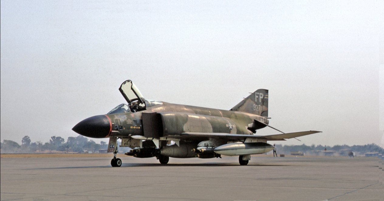
Not so fast, cowboy. The final block of F-4Cs (and initial block F-4Ds) were delivered with 'clean' radomes (like the F-4J) with no undernose sensor fairing. The fairings did reappear later.

-
Some gunners removed sections, others the entire panel to faciltate clearer vision of what lurked in the night sky.
-
RCAF Lanc 10MP. This really is a group effort
chek replied to Clunkmeister's topic in LSM 1/35 and Larger Work In Progress
I have an as yet not fully proven theory that suggests some caution when interpreting photos for Lancaster exhaust stain patterns. The (usually) wartime aircraft fitted with the exhaust shrouds tend to show soot stains on both sides of the inner engines, but only on the inner side of the outer ones. Over time, a less heavy trail may also develop from the outer side of the outer engines but it's much less common. I suspect it to be due to some kind of venturi acceleration effect caused by the shrouds. On post-war Lancs without the shrouds, the staining seems to build up fairly evenly on both sides of the outer engine across the top of the wing. Being heavier, most of the greyish/white lead deposits are stuck to the cowling sides and go under the wing, with much less evidence over the wing. No doubt there are exceptions to be found, but that seems to be the general pattern I've observed from several hundred photos, -
Build BEAUFIGHTER they said, it's FUN they said :)
chek replied to Martinnfb's topic in LSM 1/35 and Larger Work In Progress
Good going Martin, those cannon look like actual heavy armament. I guess the relative simplicity of the main gear bays is to be welcomed. -
Build BEAUFIGHTER they said, it's FUN they said :)
chek replied to Martinnfb's topic in LSM 1/35 and Larger Work In Progress
Wet sanding helps a lot in reducing heat build up when sanding the ali tube. If you have a size handy which will slide into your plastic tubes, a light greasing with vaseline or similar would allow you to build up the rear edge of your cannon troughs with some superglue and plastic power from all the sanding, and then sand it back to a curved edge as seen below. -
Build BEAUFIGHTER they said, it's FUN they said :)
chek replied to Martinnfb's topic in LSM 1/35 and Larger Work In Progress
Having done similar with a Hunter, one small tip I can offer is to ensure the nose contours remain well defined. I used auminiumi tubing on mine, and was pleased at getting not only perfectly shaped gun troughs, but a nice flange effect from the tube's thickness itself. Unfortunately, while the troughs looked great, I'd abraded and polished away too much nose which gave the poor old normally pugnacious looking Hunter's nose a decidedly skinny, receeding chinned look. For the next one, I scribed lines at the trough edges, and superglued in some phone wire with the chrome burned off and drawn through a pad of wire wool, so it was flush where the surface needed to be. Once you're sanding and the bright copper makes an appearance through the filler, you know to hang back on further heavy sanding and keep the nose shape true. -
Build BEAUFIGHTER they said, it's FUN they said :)
chek replied to Martinnfb's topic in LSM 1/35 and Larger Work In Progress
Nice work so far Martin. Be aware though that the cannon are mounted asymmetrically - due to the breeches not being handed. It's subtle and not by much, but is there. This is the best photo I can find without having access to a real Beau. -
RR Spey powered RAF Phantom conversion
chek replied to Wingco57's topic in LSM 1/35 and Larger Work In Progress
Hi Cees - another pic of the aud door interior for you.- 414 replies
-
- 3
-

-
- conversion
- phantom
- (and 1 more)
-
RR Spey powered RAF Phantom conversion
chek replied to Wingco57's topic in LSM 1/35 and Larger Work In Progress
Good progress, Cees. One suggestion involving some extra work for you: saw along the inner edges of the Sparrow bays too. If you don't, I've seen one conversion result in bent missile bays which was not a good look. It'll probably help with the spreading as well.- 414 replies
-
- 2
-
-
- conversion
- phantom
- (and 1 more)
-
RR Spey powered RAF Phantom conversion
chek replied to Wingco57's topic in LSM 1/35 and Larger Work In Progress
Also as a historical aside, Macair was considering the switch from turbojets to turbofans and the Spey (or a US built version) was to have been the powerplant for the swing-wing Phantom FVS project, had it proceeded. That was in the days when only the benefits in fuel efficiency from turbofans were seriously considered and the problems of integration (increased drag) hadn't yet been discovered.- 414 replies
-
- 1
-
-
- conversion
- phantom
- (and 1 more)
-
RR Spey powered RAF Phantom conversion
chek replied to Wingco57's topic in LSM 1/35 and Larger Work In Progress
Barry, yes the model in the lower frame showing the two fuselages looks pretty good to me and the intake rise looks about right. It will be easier to tell when it's been primered that the lines flow smoothly. My original point was directed to Cees, whose model was following Frank Mitchell's method which dealt well with the increased width, but not the depth as your model has done. I'm still holding out for the HKM version because I really wouldn't look forward to doing the home-baked conversion two or three times.- 414 replies
-
- 1
-
-
- conversion
- phantom
- (and 1 more)
-
RR Spey powered RAF Phantom conversion
chek replied to Wingco57's topic in LSM 1/35 and Larger Work In Progress
This drawing from Tommy Thomason probably shows it best. The whole Spey turbofan nacelle from intake to jetpipe was through-putting much more volume that a J79 turbojet. The intake topside has an upward slope to approx station F13 on the drawing below Regular F-4J in black, Spey mods added in red,- 414 replies
-
- 2
-
-
- conversion
- phantom
- (and 1 more)
-
RR Spey powered RAF Phantom conversion
chek replied to Wingco57's topic in LSM 1/35 and Larger Work In Progress
No Note though Cees, it's not only a widening of the intakes, but they also rise to a point about level with the rear canopy fairing. Despite Frank's valiant effort, this omission was enough to spoil the look of his method for me. The whole intake of the Spey Phantom looks like it's been cranked downwards, and without the vertical rise, you can't get enough of that downward crank.- 414 replies
-
- 3
-
-
- conversion
- phantom
- (and 1 more)