

One-Oh-Four
-
Posts
1,757 -
Joined
-
Last visited
Content Type
Profiles
Forums
Events
Gallery
Posts posted by One-Oh-Four
-
-
Fit the canopy last, don't let that slow your Meteor down.
Cees
Was nice meeting up with you at the Aviation Megastore yesterday! As we discussed the Meteor too; I WILL let the canopy slow the Meteor down. It may be my own autism-thingy but I can't put my heart and soul in a build if not all the parts are sorted. I then have simply a fear that the whole model would sit almost finished for months in the cabinet, waiting for that last part.... And yeah, even with my track record of finished builds I have that fear....
So the Meteor goes on hold for a little while. In the near future, Huub and I are going to try to make a master for a vacform canopy. If that's succesful and I find someone that can form the canopy, the race is on again!
In the meantime, since I have also bought HK's Mosquito, I'll start that build! I'm looking forward to extra detail the cockpit on that one!
-
Just ordered the HK Mossie and PM stencils at the Aviation MegaStore!

-
 3
3
-
-
Jeroen, is it worth the extra price to get the ProfiModeller stencils as HK provides stencils in the kit?
-
Wow! Great model, really original to finish it as an air racer!!
-
2
-
-
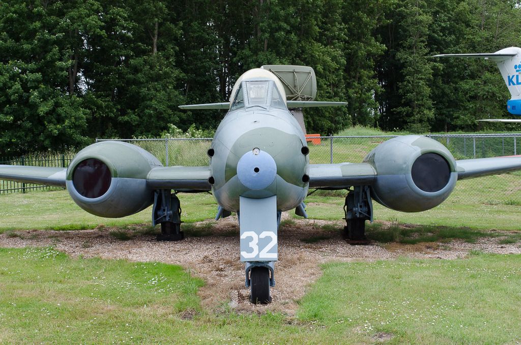
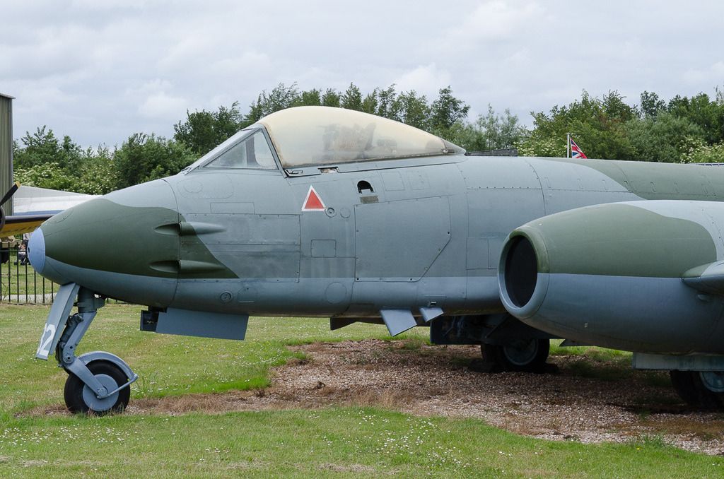
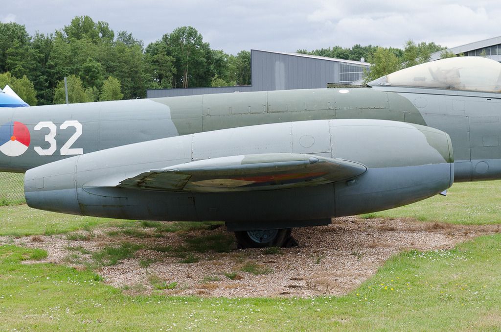
Gloster Meteor F.8 Walk-Around
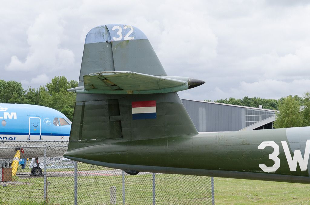
In March 1953, the Fokker built Gloster Meteor F.Mk.8 c/n 6466 was delivered at Soesterberg as '3W-50' to the 322 sqdn. of the L.S.K. Within a week the aircraft was damaged in a landing accident. The aircraft re-entered service in November 1953. The next incident with this airframe, re-serialed '3W-50', took place in May 1954. The canopy exploded in flight. In spite of the damage the aircraft landed safe. October 1956 the aircraft re-entered service as '7E-12' with the 327 squadron. Early 1957, the Meteor was moved to the 322 sqdn. as '3W-32'. On 28 May 1958, the airframe was phased out, but the Meteor survived as a monument at Soesterberg AFB. Since 1958, the Meteor was on static display first as 'I-187', but in 1981 the registration on the aircraft was changed to 'I-147'. Striking on the displayed aircraft is that it carried the red of the 327 squadron at the top of the tail and on the nose, although the last operator was 322 squadron that carried blue... After over forty years of open-air display at Soesterberg AB the airframe was in bad condition and the canopy was missing.
On 14 February 2006 this Meteor F.8 arrived at Hoogeveen airfield. The new owner of the Meteor was ATN Aircraft Division, a specialist in restoration of aircrafts. After the restoration of the aircraft, it should be displayed on a pile at Hoogeveen airfield. This plan did not go through and the aircraft was donated to Aviodrome. Early 2009, the Gloster Meteor was moved to Lelystad. Today, the aircraft is displayed as 3W-32 in the Royal Netherlands Air Force '322 Squadron' colours by Aviodrome at Lelystad.
Text: Jack Wolbrink; avia-dejavu.net
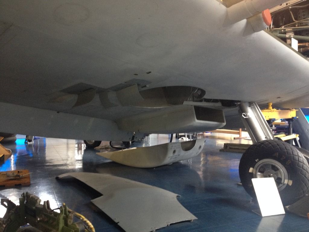
Interesting to see is that the aircraft is fitted with the late all-plexiglass hood but not with the big breather intakes! Other F.8's in the Royal Netherlands' Air Force were, however, photographic evidence exists. Do note that the F.8 had different trim tabs on the ailerons than the F.4. A difference that is not addressed in the Fisher conversion set.
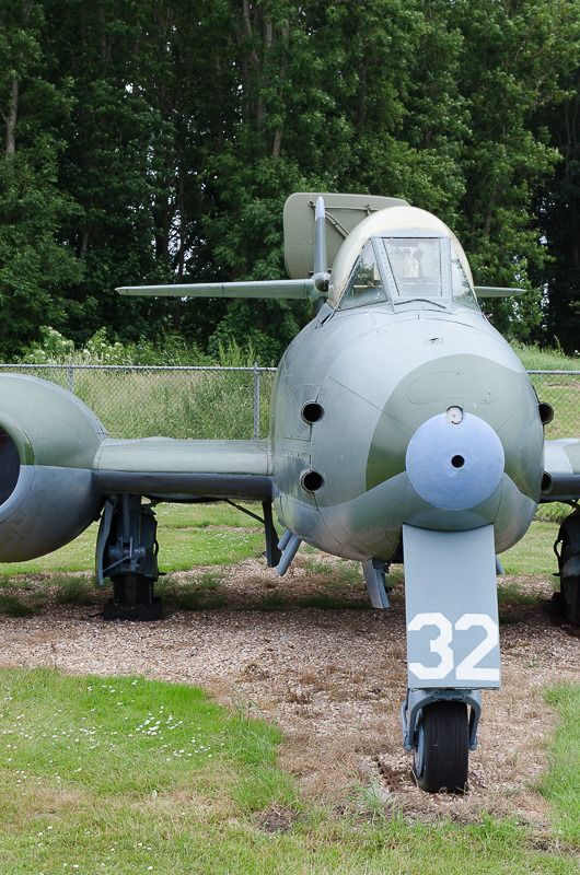
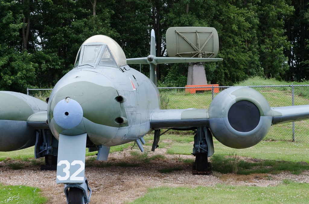
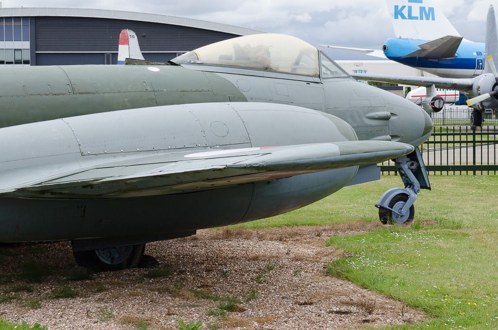
A couple of photos to get a feel of the curvature of the fuselage at the cockpit. Since I'm of the opinion that the standard HK F.4 canopy is too squat I was wondering if the fuselage of the model may be too wide. Luckily that seems not to be the case!
The profile of the leading edge of the wing. Sand the kit's leading edges to this profile:
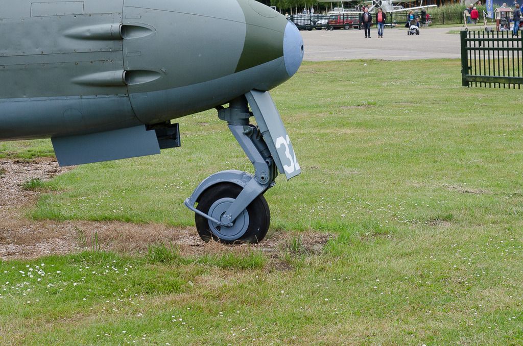
The stance of the nose wheel. It may be that this is too high since the a/c is basically a hollow shell but the nose-low stances on other museum aircraft are because of leaks in the oleos.
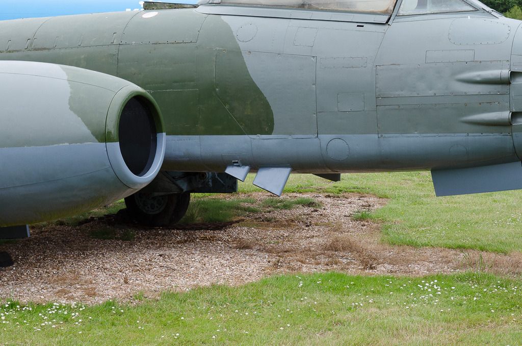
The standard intake. As can be seen the Fisher correction is very good!
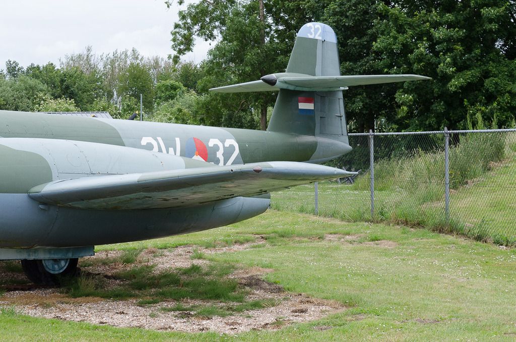
The wing tip.
At the aft end of the tip is -what I believe- the fuel dump nozzle.
The Meteor F.8 had two trim tabs spanning the length of the ailerons as opposed to the single tabs of the F.4.
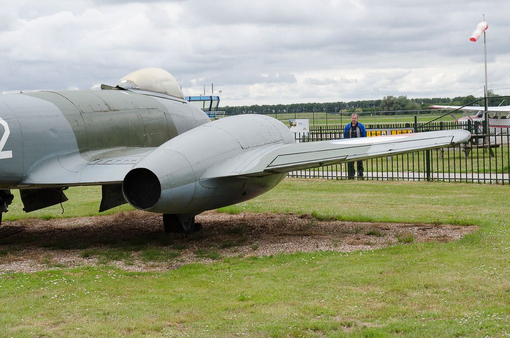
Both upper and lower (the trim tab actually) rudder parts have a metal strip at the trailing end as opposed the F.4 where only the upper part has it.
Cheers,
Erik.
-
1
-
-
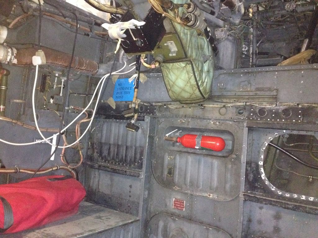
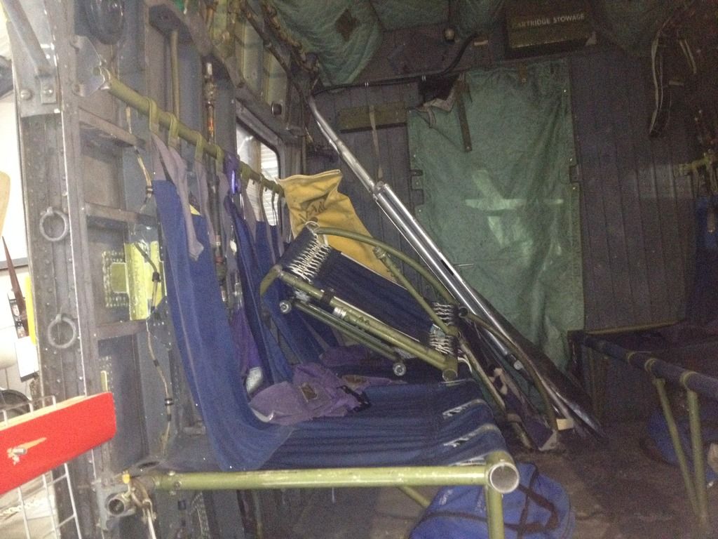
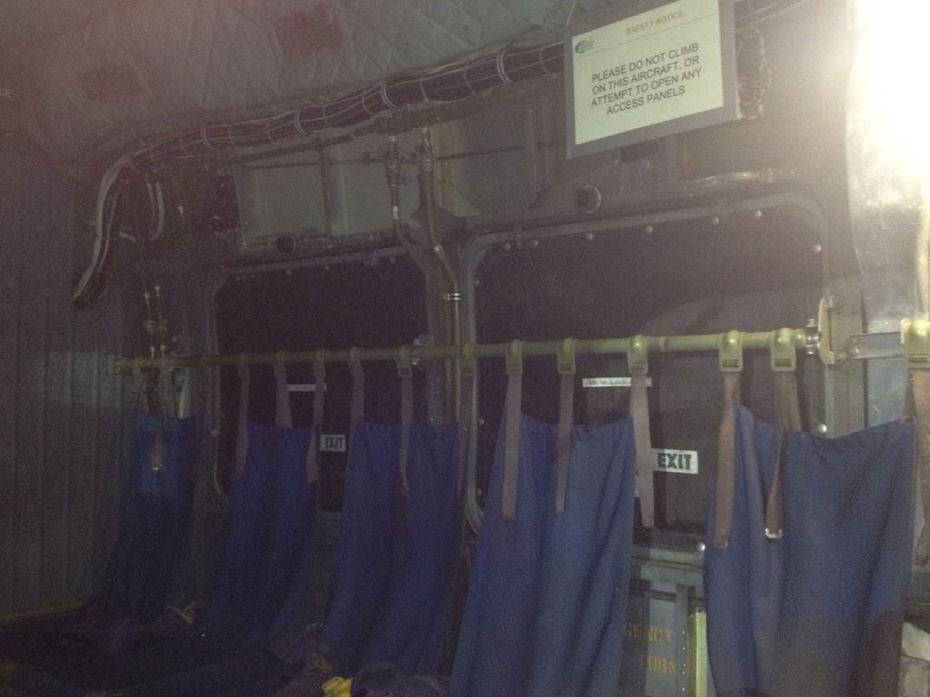
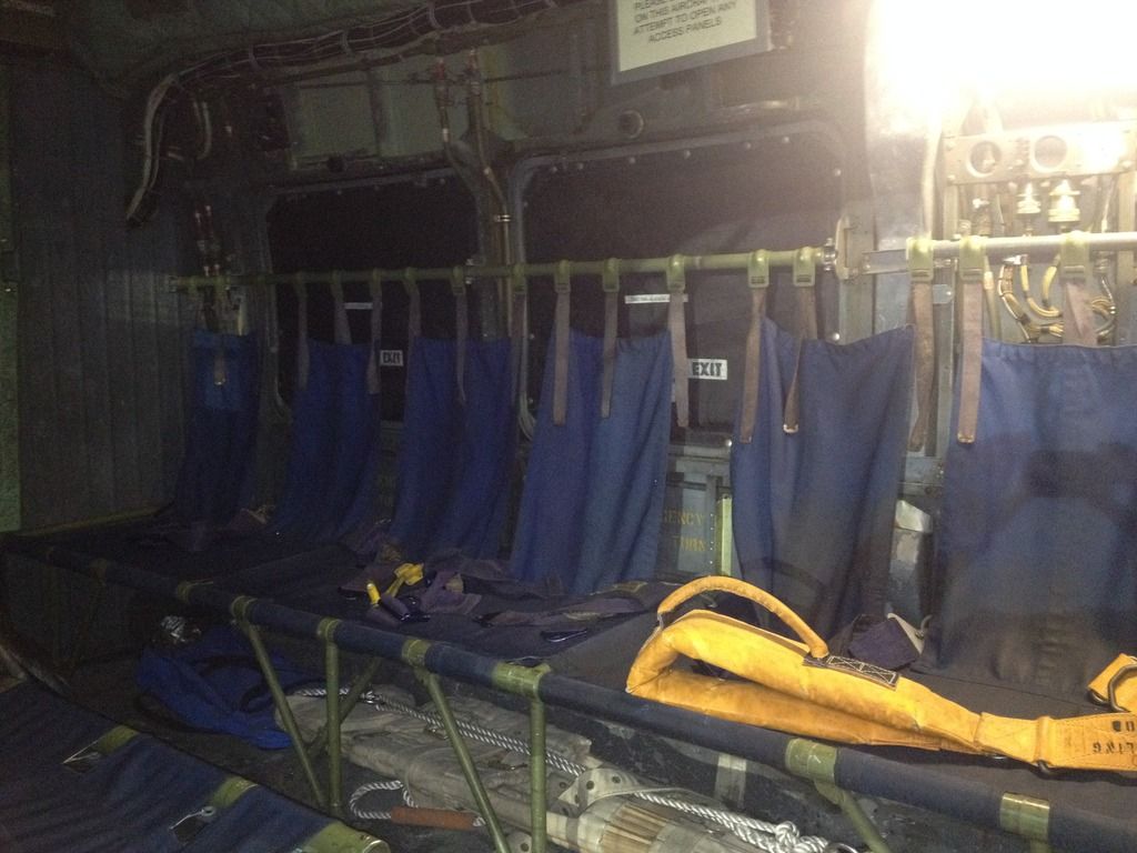
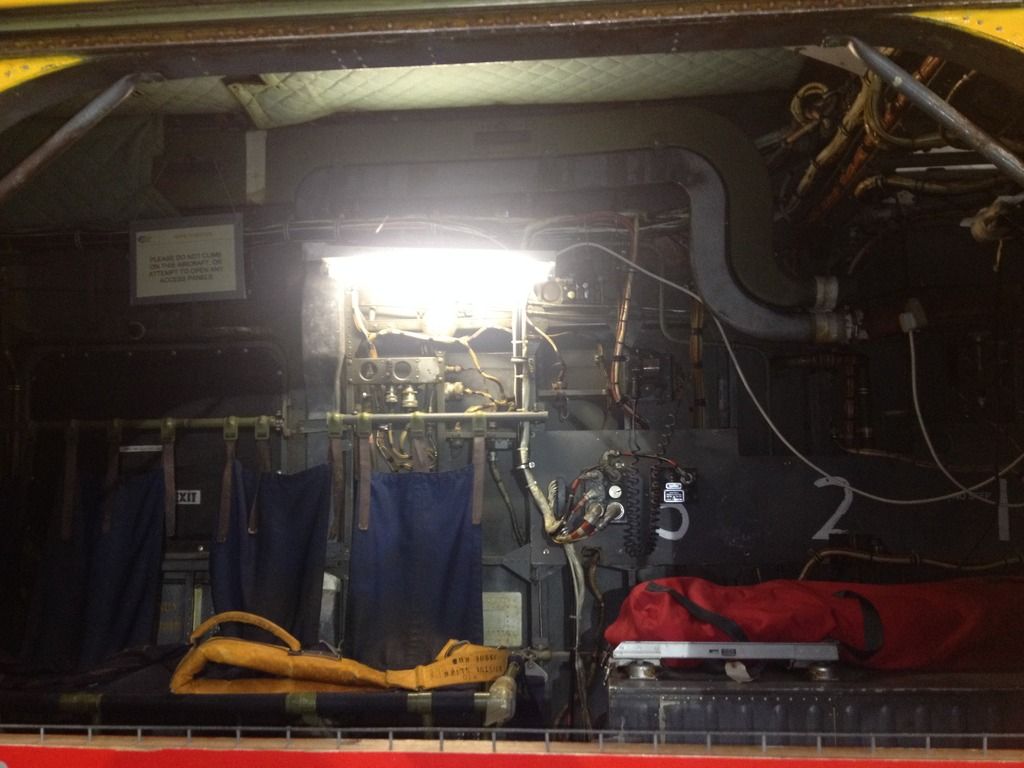
Cargo/passenger compartment Wessex HU.5
In the Manston Airfield Museum, one can find a Wessex HU.5 in HC.2 RAF Rescue colours. Anticipating the Fly Models 1/32 Wessex HU.5, I decided to take some shots of the cargo/passenger compartment. Not wanting to dig through the kit on my motorbike to get to my Nikon, I once again used my iPhone to take the pics....
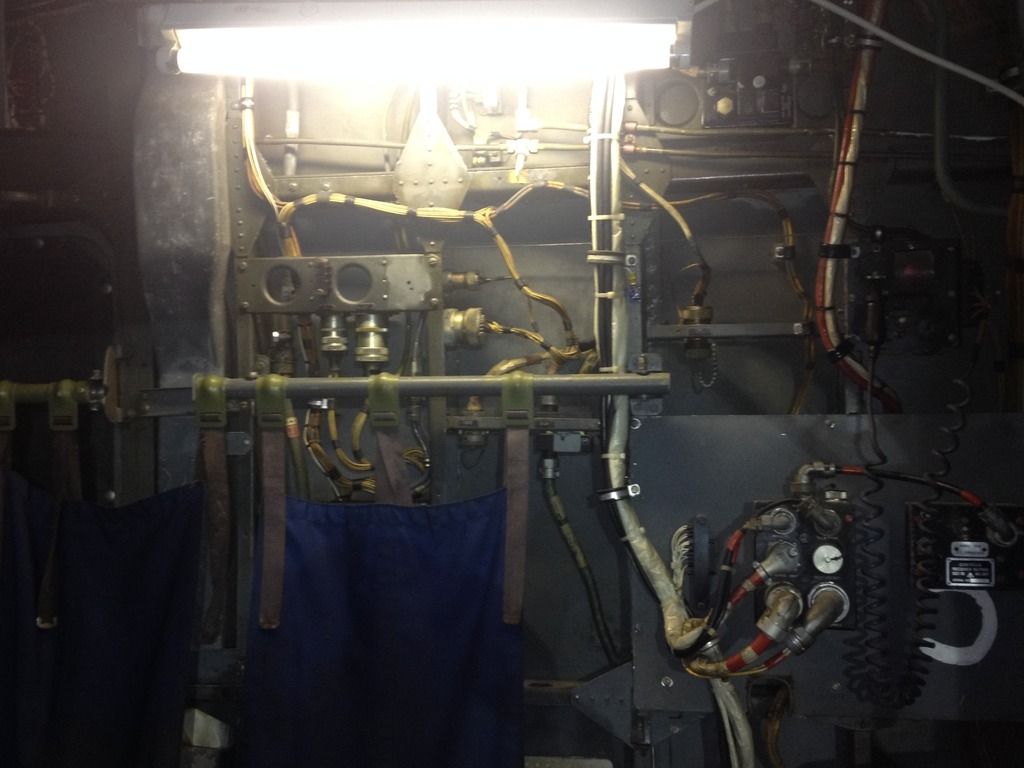
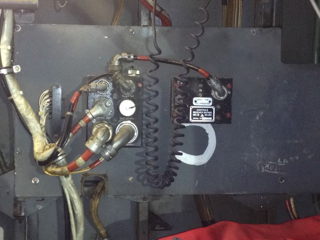
The front bulkhead, the pilots' seats are located in the "void" above:
The right sidewall in front of the sliding door. Two seats and the hoist controls:
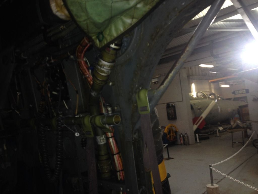
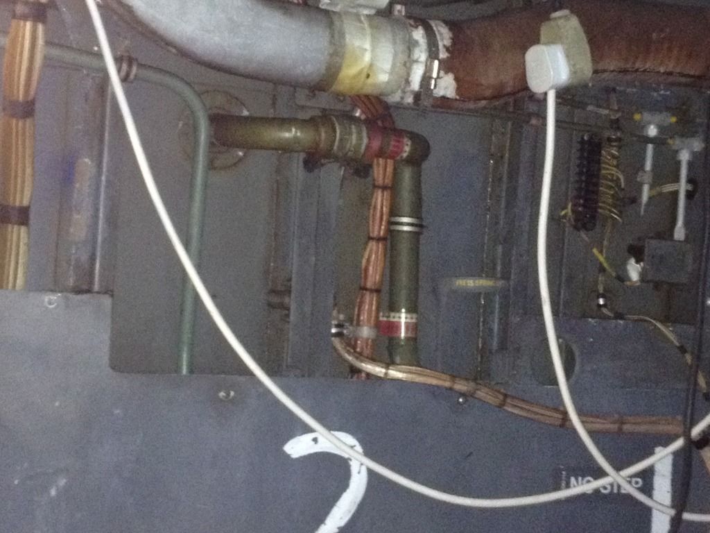
The right sidewall aft of the sliding door:
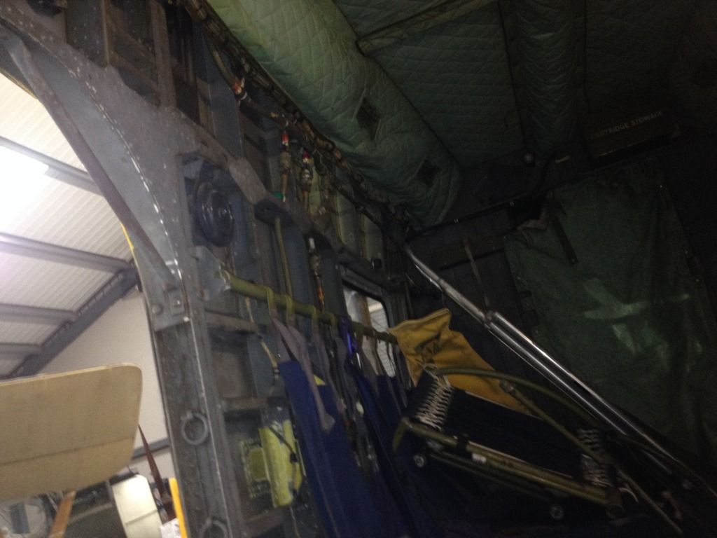
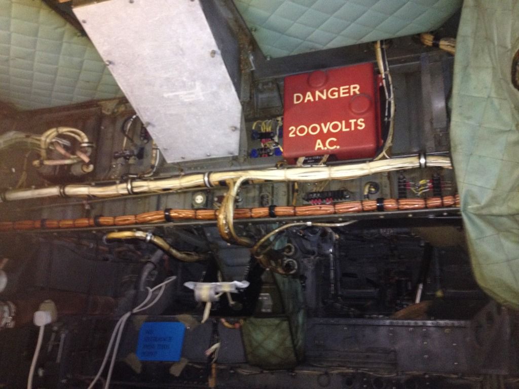
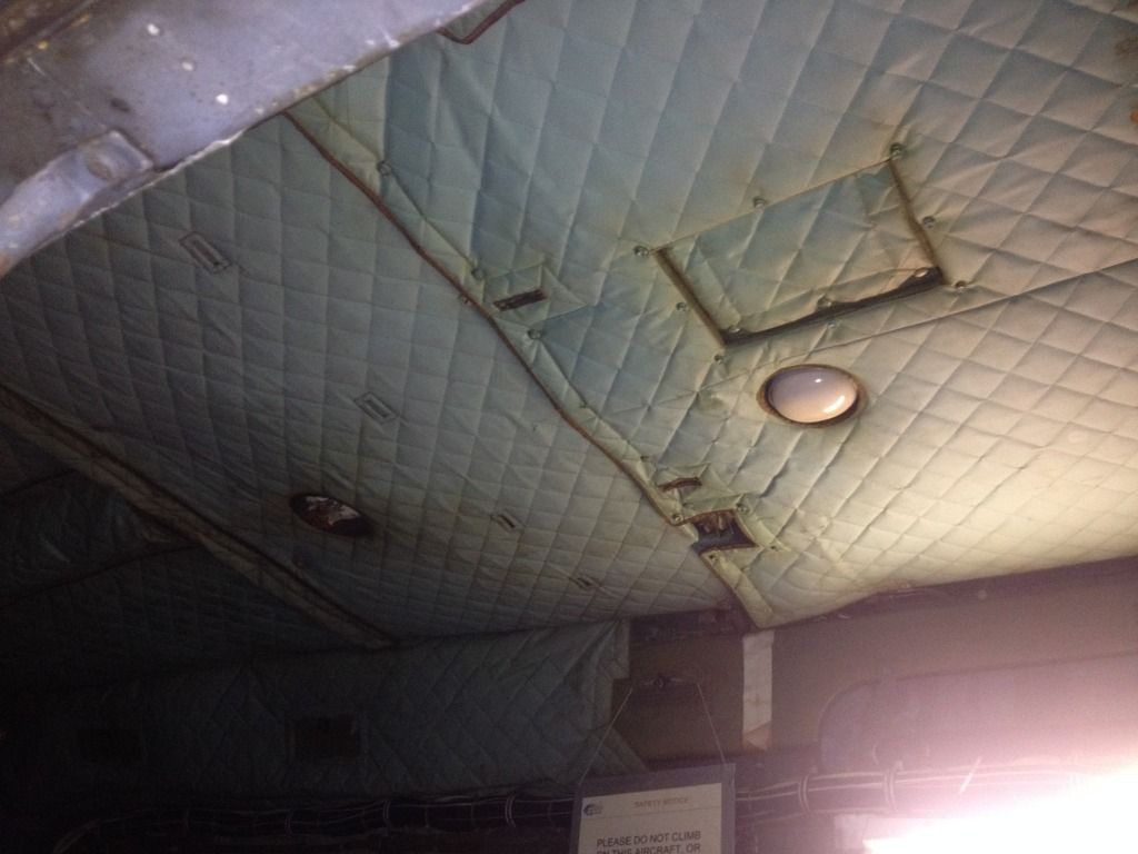
The ceiling above the sliding door:
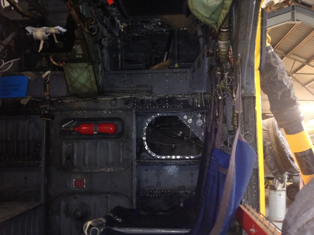
The rear bulkhead:
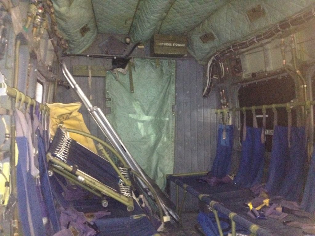
The opposite (left) sidewall:
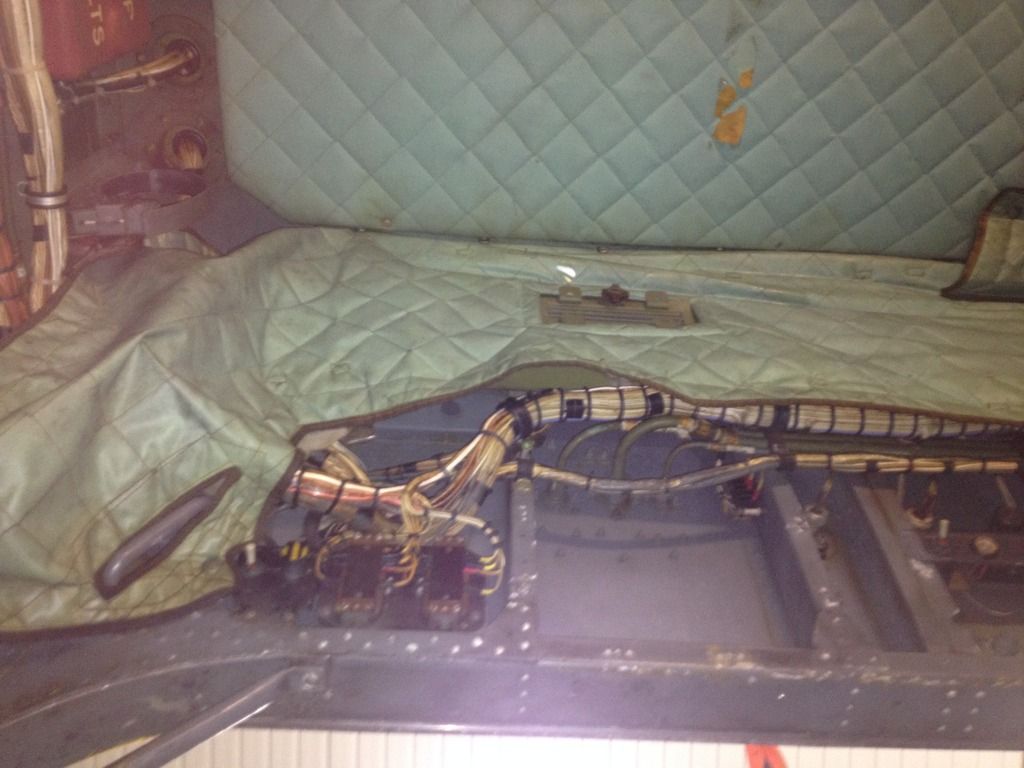
The ceiling of the compartment. Above the soundproofing is the gearbox of the main rotor and the shaft driving the tail rotor. The angled metal part on the right encloses the main shaft from the engines to the main rotor gearbox.
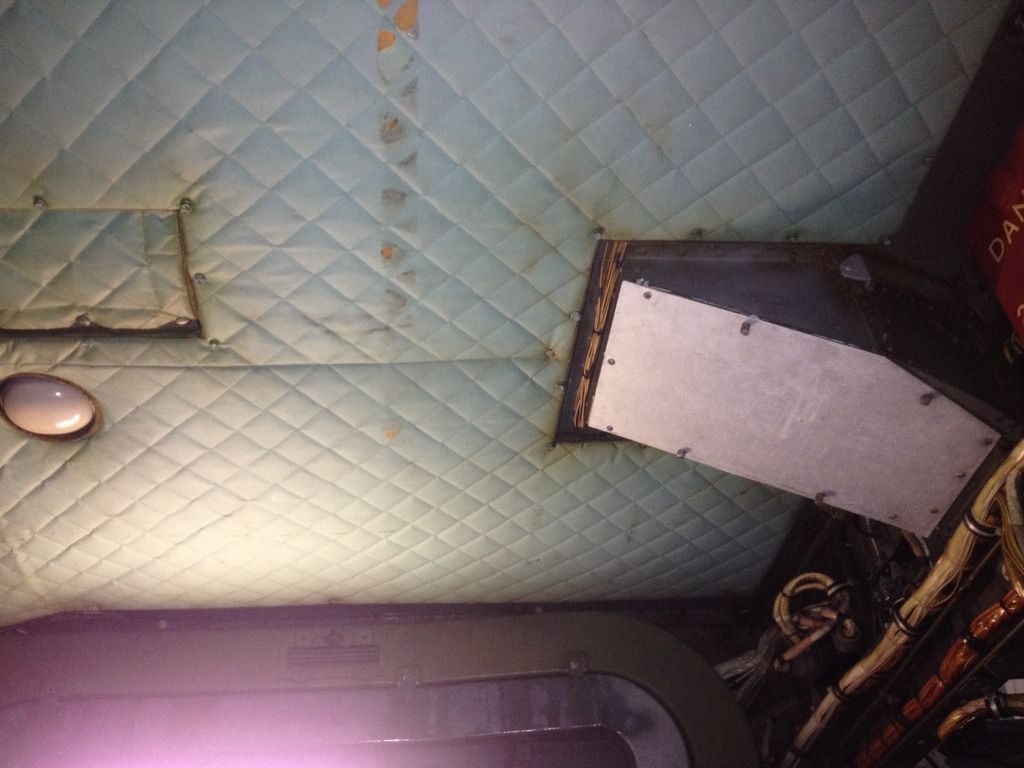
I hope these pics are some use to you when building the 1/48 Italeri or 1/32 Fly Junglie Wessex!
Cheers,
Erik.
-
I don't know about Italeri. I've read that the Revell Mirage III is quite correct in it's outline. Treat it as a vacform of which the parts are already cut out.... In any case you are going to need this:
Fisher Mirage III cockpit set for the Revell kit
and for an exhaust:
I know it isn't about an Italeri release, maybe with these sets your pole is shortened to 3 feet?
Cheers,
Erik.
-
1
-
-
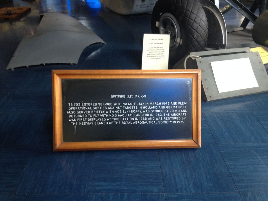
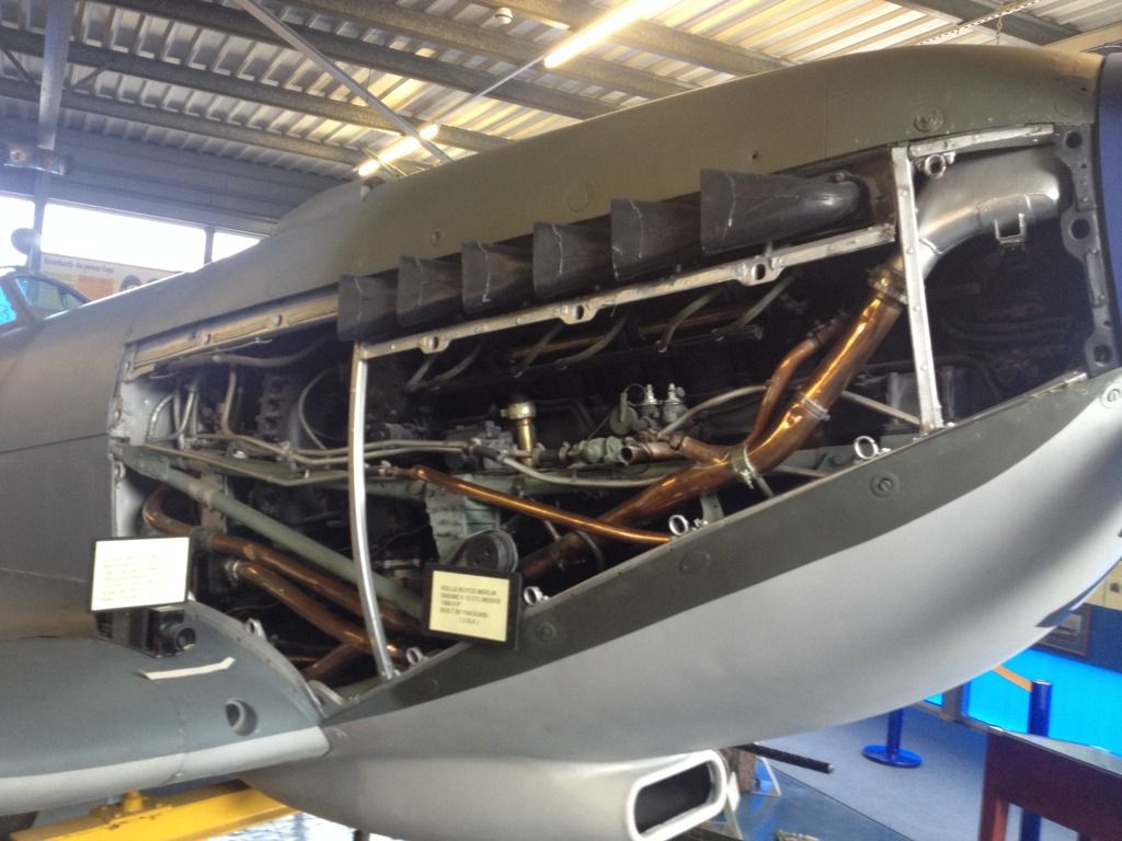
Spitfire LF. Mk.XVI engine & armament photos.
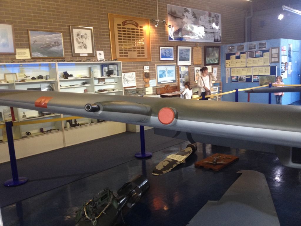
Last Sunday on the way back from Flying Legends at Duxford I visited the Spitfire Memorial at Manston. They have a Spitfire LF. Mk. XVI on display, complete with 250LBS & 500LBS bombs plus wing hardpoints. The remarkable thing about this Spitfire is that it's fitted with the "e"-wing but it's quite clear that it's in fact a modified "c"-wing, since it has the .303 gun apertures in the wing leading edge and the cartridge/link ejector chutes underneath the wings. Also remarkable are the deflectors underneath the wings to guide the cartridges/links clear of the bombs. I have no idea if this was a post-war mod or already in use during the war.
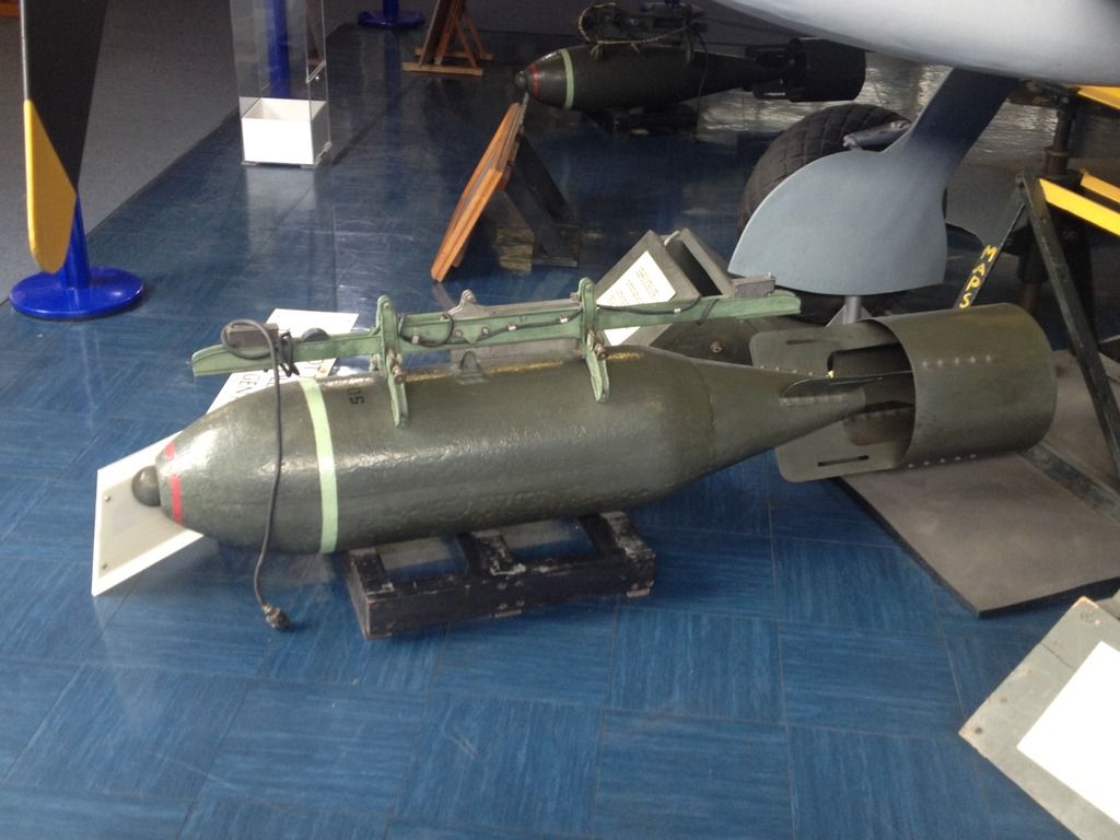
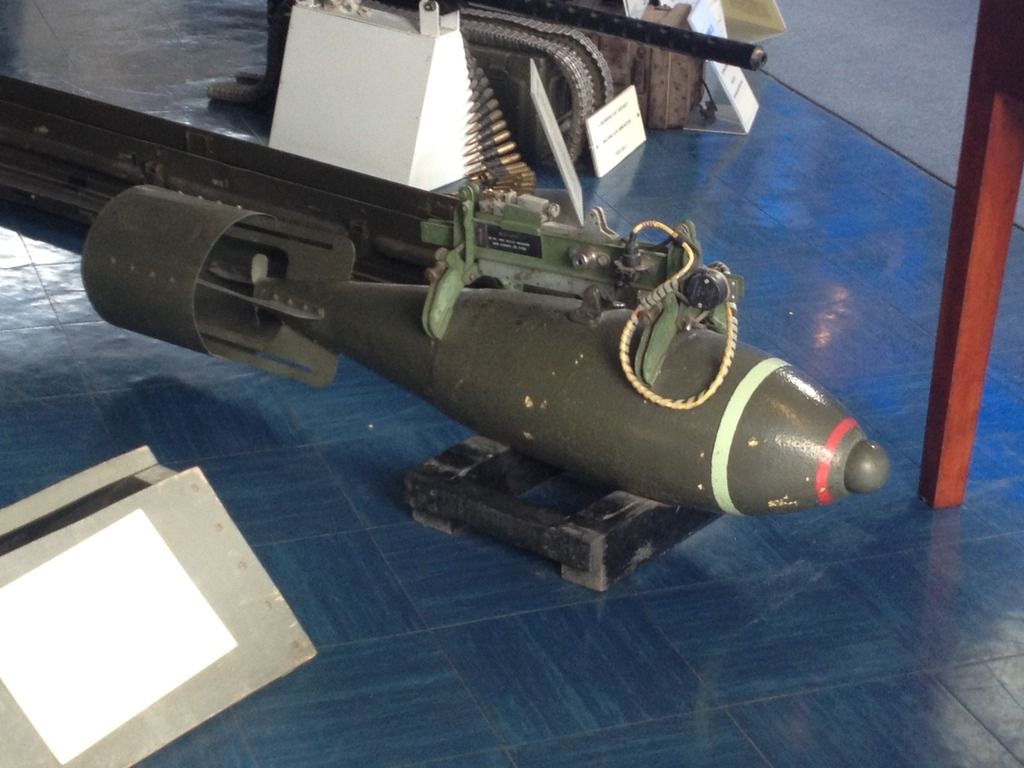
The 500-pounder:
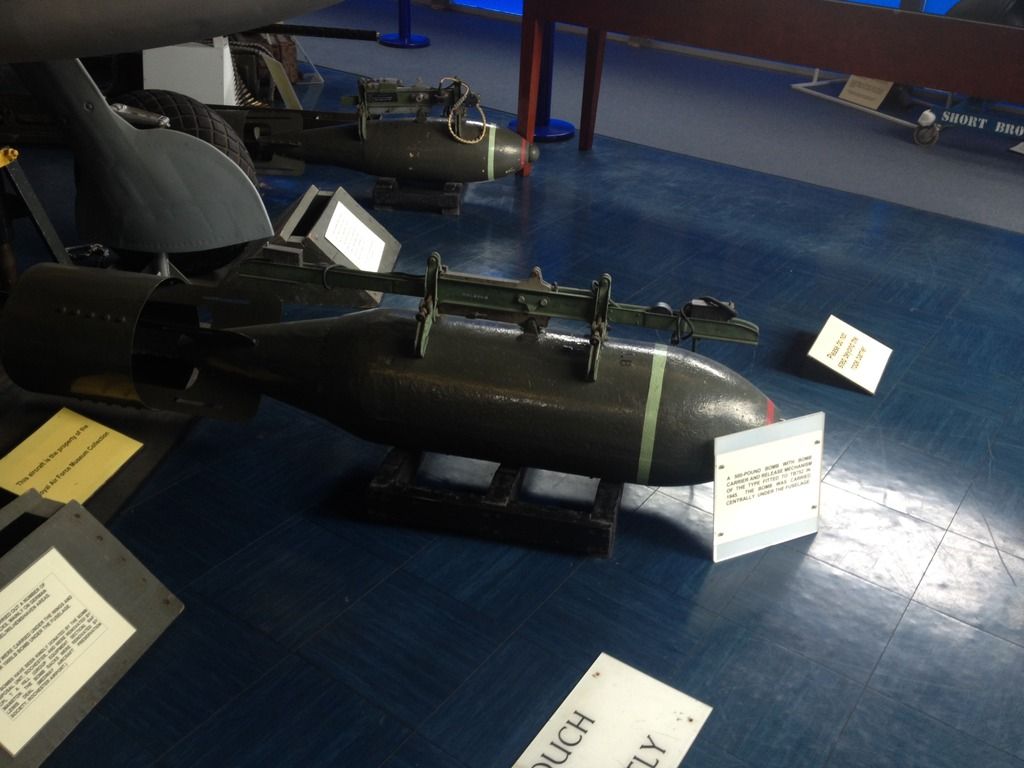
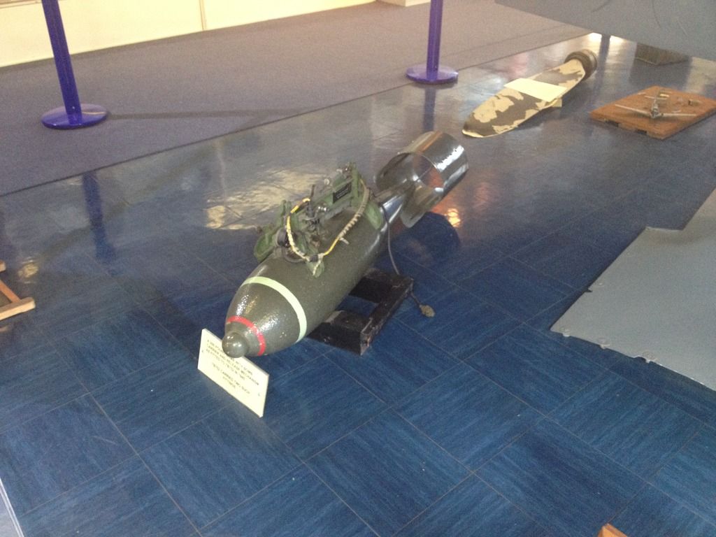
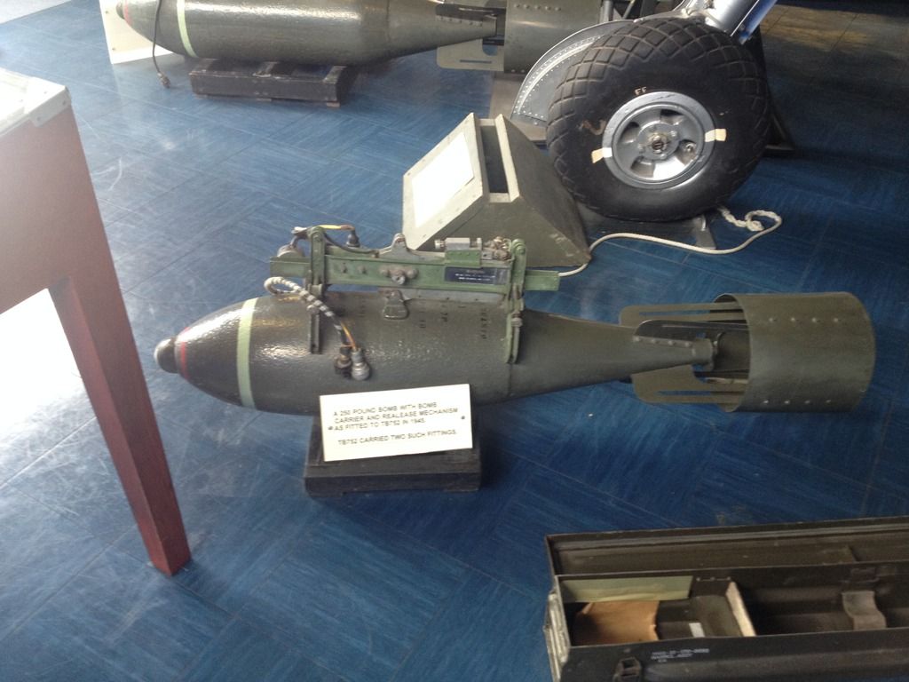
The 250-pounder:
The Hispano 20mm gun:
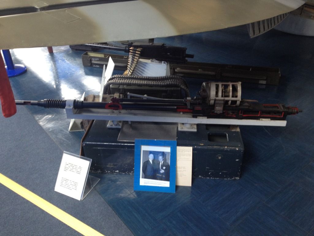
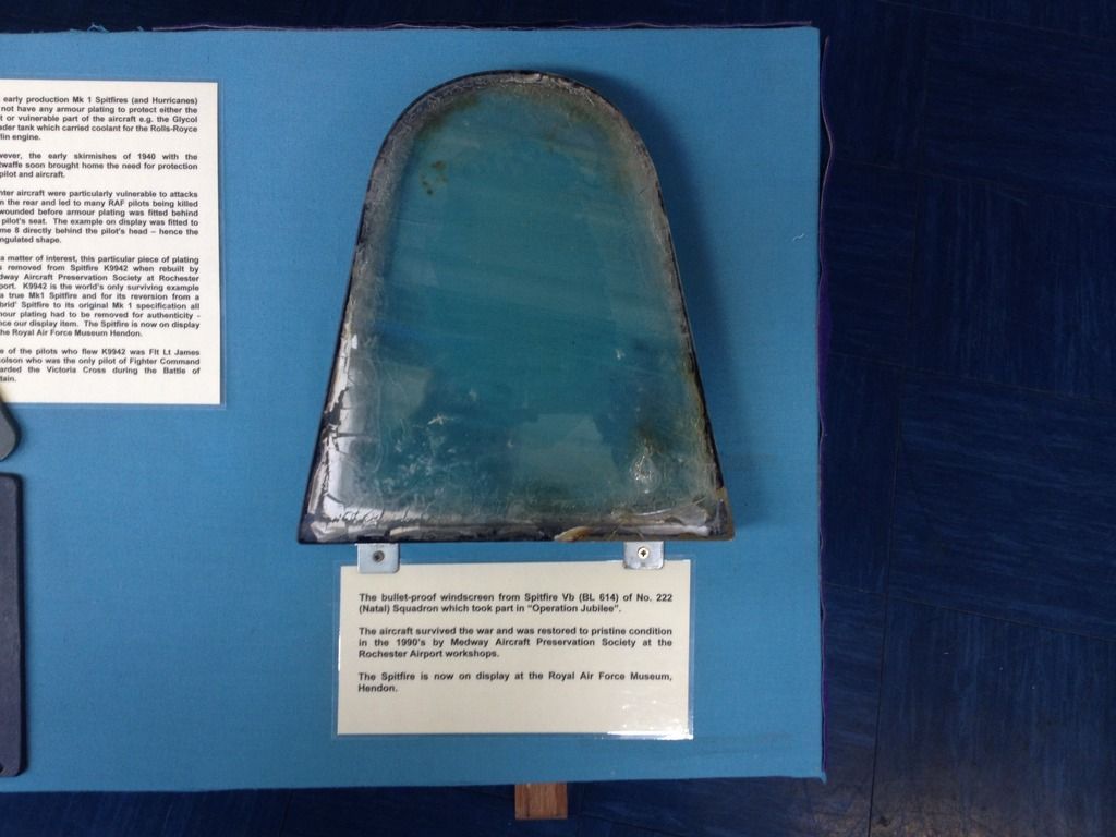
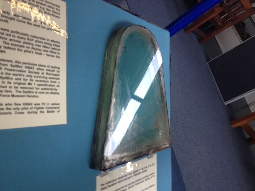
The armored windscreen of a Spitfire Mk.V:
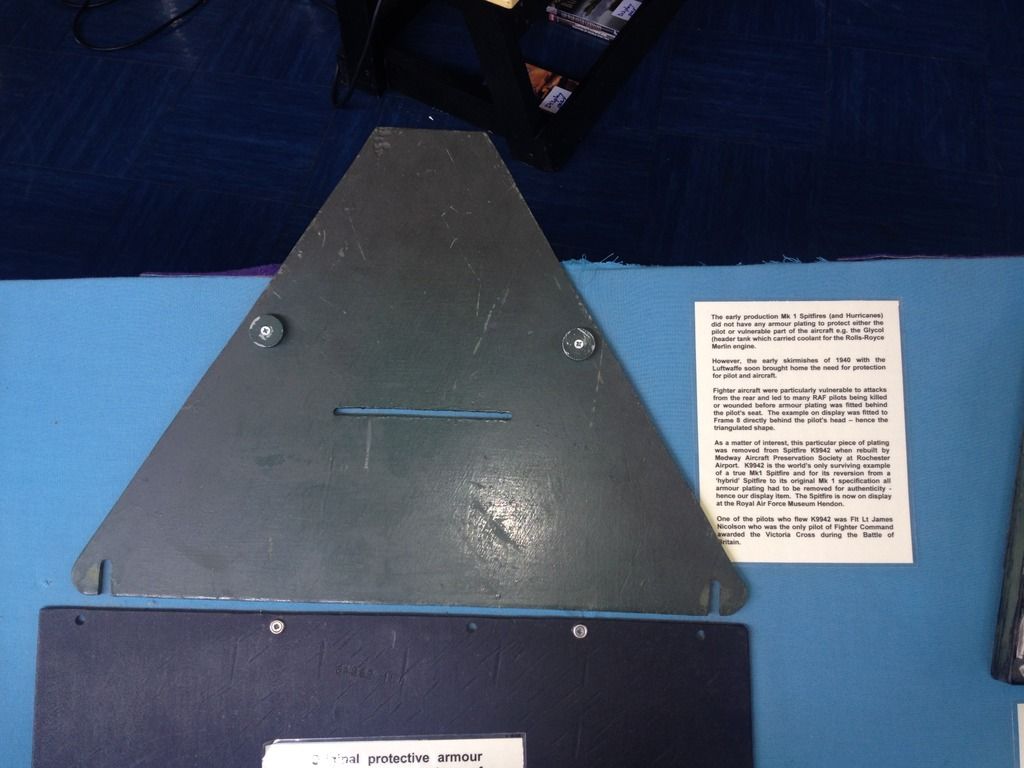
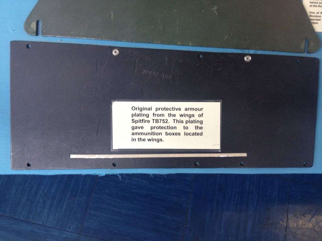
This back-amour was retro-fitted to a Spitfire Mk.I. When the airframe was completely restored to original Mk.I fit, the armour was removed from the cockpit and ended up in the museum.
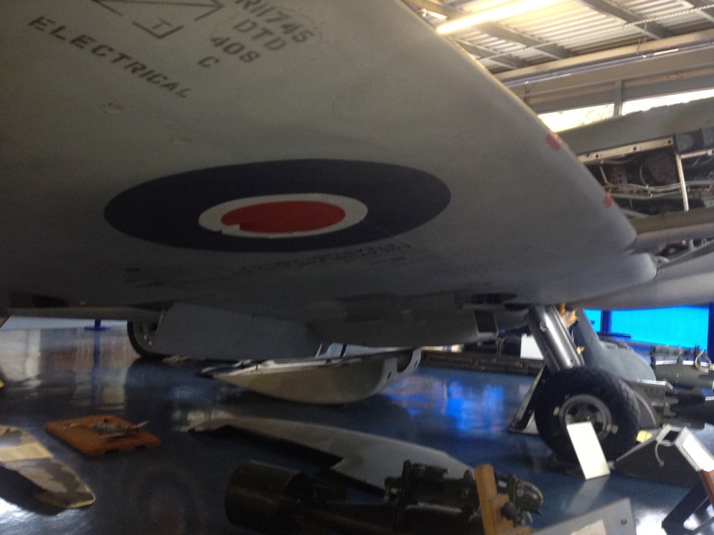
The "e"-wing armament of this Mk.XVI. The rounded "later" cannon-tubes can be clearly seen, but also the taped .303 gun openings. Underneath the wing the shell ejector chutes for the .303's may also be observed:
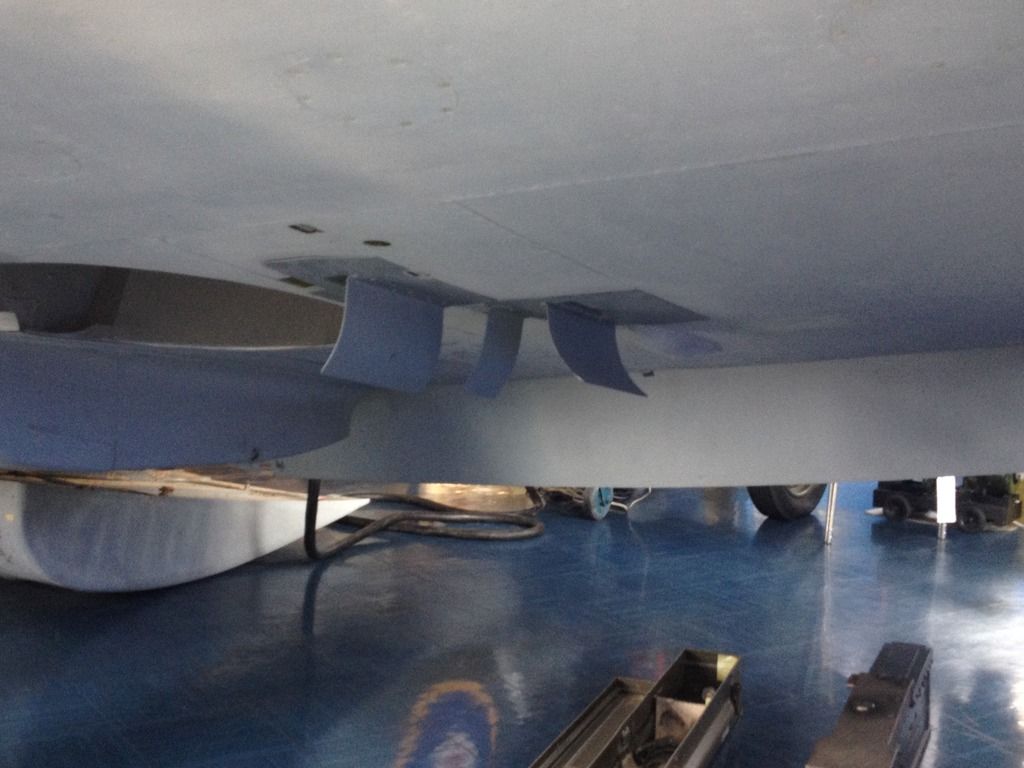
The afore mentioned deflectors:
Wooden prop blade of the Rotol airscrew. The leading edge was strengthened with copper strip.
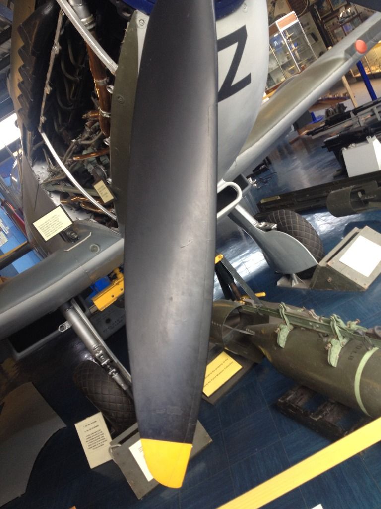
I made these photos with my iPhone, so quality lacks a little. However, I hope these photos may be of some use to you.
Cheers,
Erik.
-
1
-
-
Off to a great start, Jason!!
-
Hi Wouter,
Thnx! I'll bring it to Nieuwegein if i can
Cheers,
Jeroen
You can, you will and you WILL enter it in the competition there, too! Otherwise I'll whip your peachy ass!!!!

-
Thnx guys!
Yes, it's my intention to bring it to telford.
Not to enter in competition, but display.
Cheers,
Jeroen
Just enter it in the competition, Jeroen! I think you might be pleasantly surprised by the results of the judging. And no, I don't judge 1/32, or the vac/resin categories, nor do I know the people (personally) who do / will. But I have seen the results of the last 15 years and based upon that, an award might just be possible!
BTW, great model! But I did't really need to say that anymore, did I?
-
Yes, and I'll saw the head armor loose from the aft cockpit bulkhead so the canopy, head armor and fixed aft canopy can be replaced!
-
-
Still in the UK, some pics from my iPhone, so awful quality..
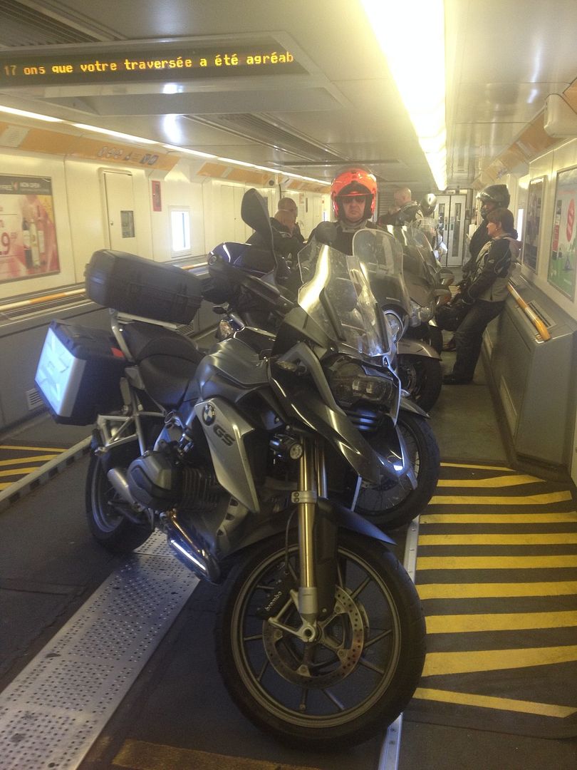

-
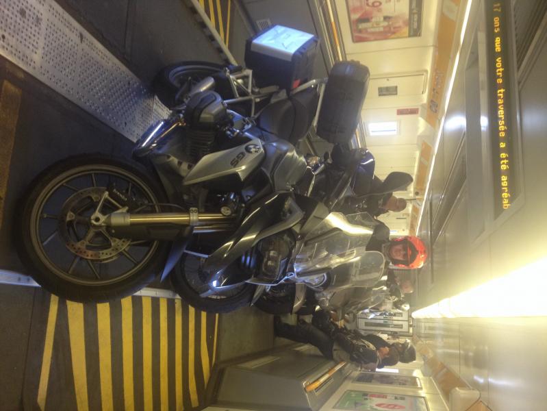
I cheated a little, I tool the Shuttle-train from Calais to Folkestone...
-
Time to get your license for motorbikes, Jeroen. Seeing as you're an Alfa (Romeo) male, you'd be just the type to ride a Ducati!
-
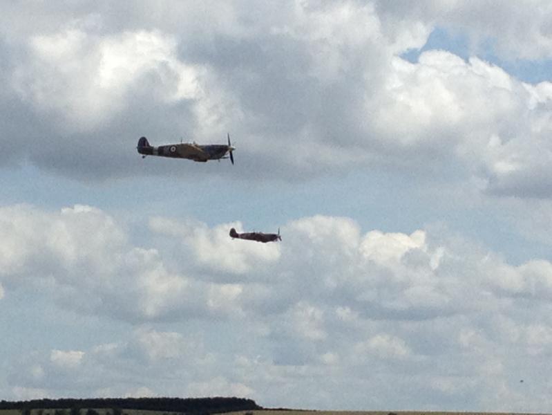
I'm off on the motorbike to England tomorrow, to visit Flying Legends. Any other LSM Members present at Duxford?
Cheers,
Erik.
-
Wellllllll, building the F.4 looks to be rather trouble-free and potentially
fast. I'm not convinced by the curvature of the sliding (and fixed aft) hood and still waiting for Paul Fisher's F.4 canopy correction set. But if that shape doesn't bother you, chances are that the shape of the front of the engine nacelle doesn't either. Get one and build it!Converting the F.4 into the F.8 with the Fisher set is somewhat more involved.......
-
That really looks great! Imagine the trouble you'd get over here in the Netherlands if you were to take that Work In Progress to your local IPMS meeting!

-
1
-
-
Eduard F-104C Exterior set for Italeri kit.
Product number 32 363.
Available from many online stores or directly from Eduard for €18,75.
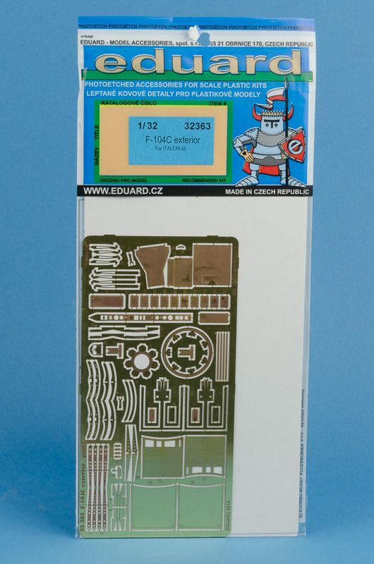
This set is practically the same as the Exterior set for the F-104G. The big difference is that you get an extra PE fret for the same price as the sole fret in the F-104 G set. That second fret contains details for the Mk117 bombs, the AIM-9B Sidewinders as well as the Sidewinder launchers and wing pylons in the bombing configuration.
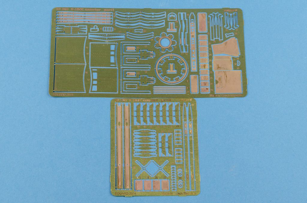
The main fret basically contains parts for new airbrakes and details for the airbrake wells. The airbrakes are pretty involved assemblies, requiring the builder to add a rib-pattern with a ball-point or similar and the build up the brake from an outer part, inner part and several ribs. It has the potential to look stunning, but be sure to use a quality folding tool to get nice straight lines. Remember also that when parked, the F-104’s airbrakes were usually closed, they were only opened for inspection, maintenance and during the start-up procedure. The rest of this set provides some details for the tailhook, the underside of the centerline pylon, parts for the flameholder of the afterburner, a small part for the gun aperture that doesn’t add much in my opinion and some panels that you are supposed to glue on top of the aircraft “skin”. Although these panels can be seen on photos of the Starfighter, they don’t stand proud of the rest of the skin. I wouldn’t bother unless you’ll try try to fit the spine panels 25 and 11 in the spine. In that case you’ll heve better defined details than the soft kit panellines. What is indeed a useful detail is part 34, on the real aircraft that is a reinforcement panel on the dragchute housing. During every landing that housing opens downward and “scrapes” the tailhook!
Click here to view the instructions.
It is a nice set, for sure, but in my opinion only the airbrake parts make it stand out, and as noted above, those were usually closed during daily operations. If you have the F-104G kit, I'd buy this set instead of the dedicated F-104G set as it isn't that dedicated and this set gives you extra details for the same price.
Because a lot of the parts in this set aren't a clear cut enhancement to the base kit in my opinion I will give this set only a:
Recommended
I'd like to thank Eduard for providing the review sample
-
1
-
-
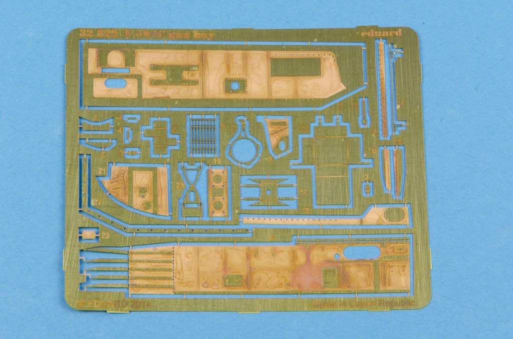
Eduard F-104C Gun Bay set for Italeri
Product number 32 822
Available from many online stores or directly from Eduard for €14,95
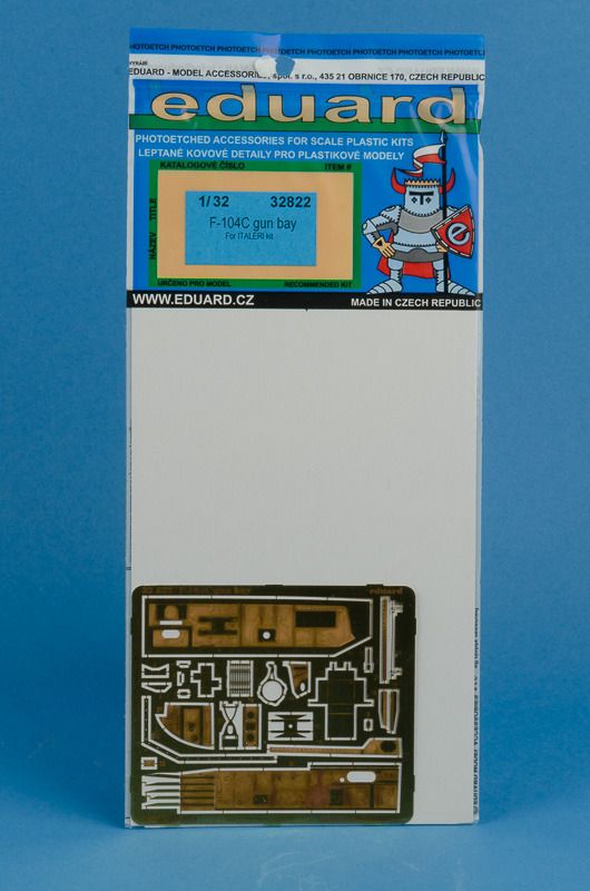
This set adds some nice details to the basic kit part. Keep in mind though, that usually only the hinging aft hatch was opened for day-to-day maintenance / checks. Only for more extensive maintenace was the front hatch removed.
And the compartment in real life:
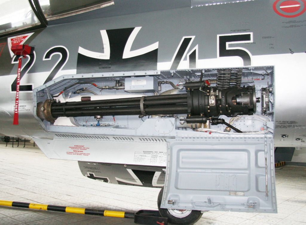
Michael Wolf
These photos give a bit of insight how the compartment looks with the M61A1 gun removed:
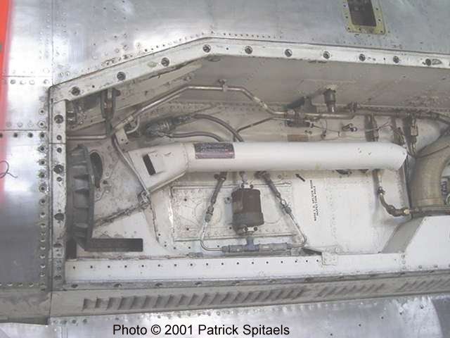
Patrick Spitaels, aircraftresourcecenter.com
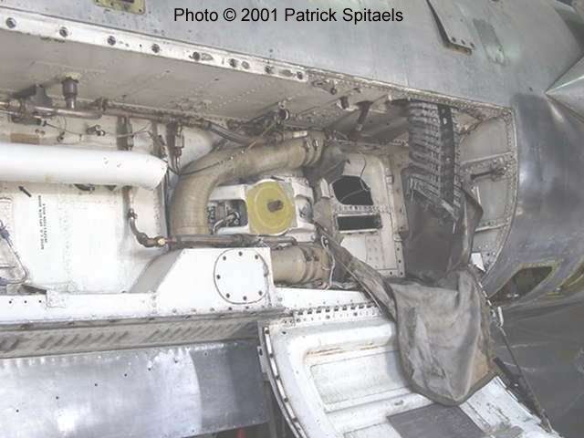
Patrick Spitaels, aircraftresourcecenter.com
As can be seen, the compartment will need some wiring added as well. If you are planning to add this detail to the bay itself, I'd recommend putting in the Master barrel set for the M61A1 Vulcan gun too!
The Eduard instructions.
There were no differences in the gun compartments between the F-104A, C and G that I'm aware of, so this set can also be used for Italeri's F-104G.
Highly Recommended
I'd like to thank Eduard for providing the review sample.
-
1
-
-
Very nice review, makes me want to buy one too!
-
Eduard F-104C Interior Set
Product Number 32 819 for Italeri
Available from many online stores or directly from Eduard for €22,95
As mentioned in the F-104A Zoom-set review, Eduard also markets sets with more details than just the bare necessities. This is such a set for the F-104C. Although the coloured fret at first looks like it's the same as the one provided in the F-104A set, that isn't the case.
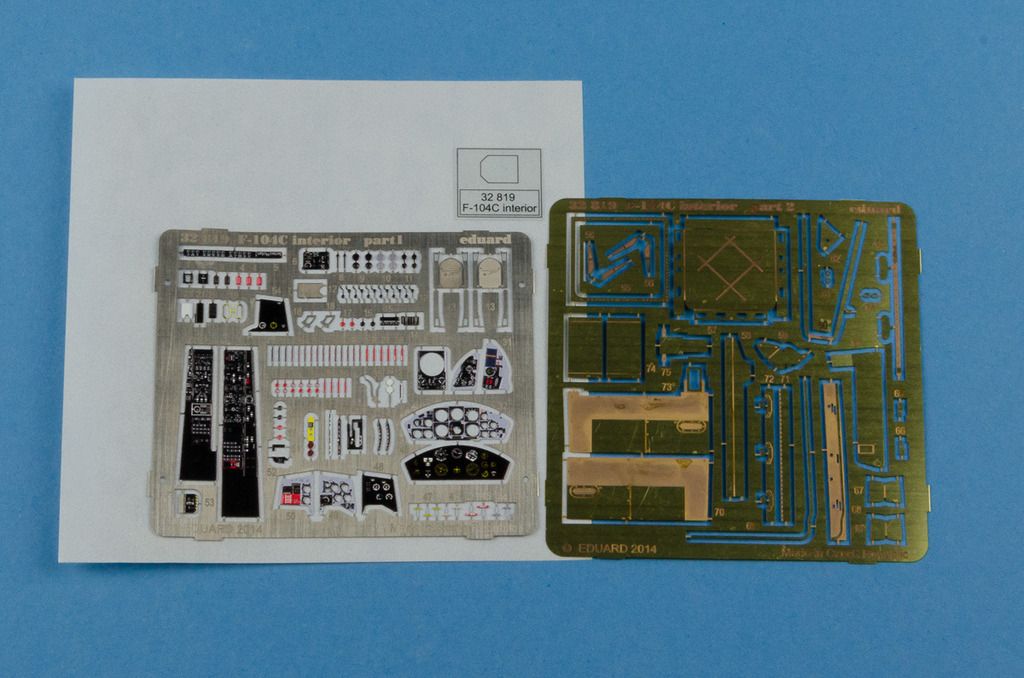
If you look at the right side of the main IP you see one of the main differences between the F-104A and -C IP's. The F-104A has three small gauges above each other (tachometer, exhaust temperature gauge and exhaust nozzle position indicator) flanked on the right side by one large gauge; the fuel quantity indicator. The F-104C has those same three gauges, but on the right side one can find three small gauges instead of one large: the fuel flow indicator, oil pressure gauge and the automatic pitch control indicator. Eduard copied this admirably.
What is probably NOT accurate is part 50; the armament control panel. As in the F-104A set, the part of the gunsight control switches is red, which is not the case on the F-104C in the Air Force Museum; F-104C-5-LO 56-914. BTW, note the triangular shaped ejection handle on this C2 seat, indicative that it's an early C2:
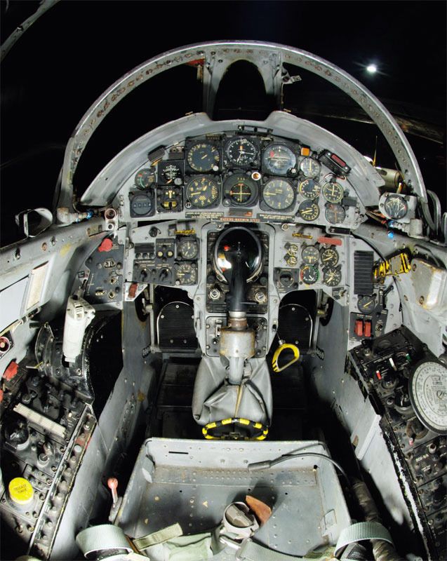
militaryfactory.com
Michael Benolkin, TacAir Publications
Michael Benolkin, TacAir Publications
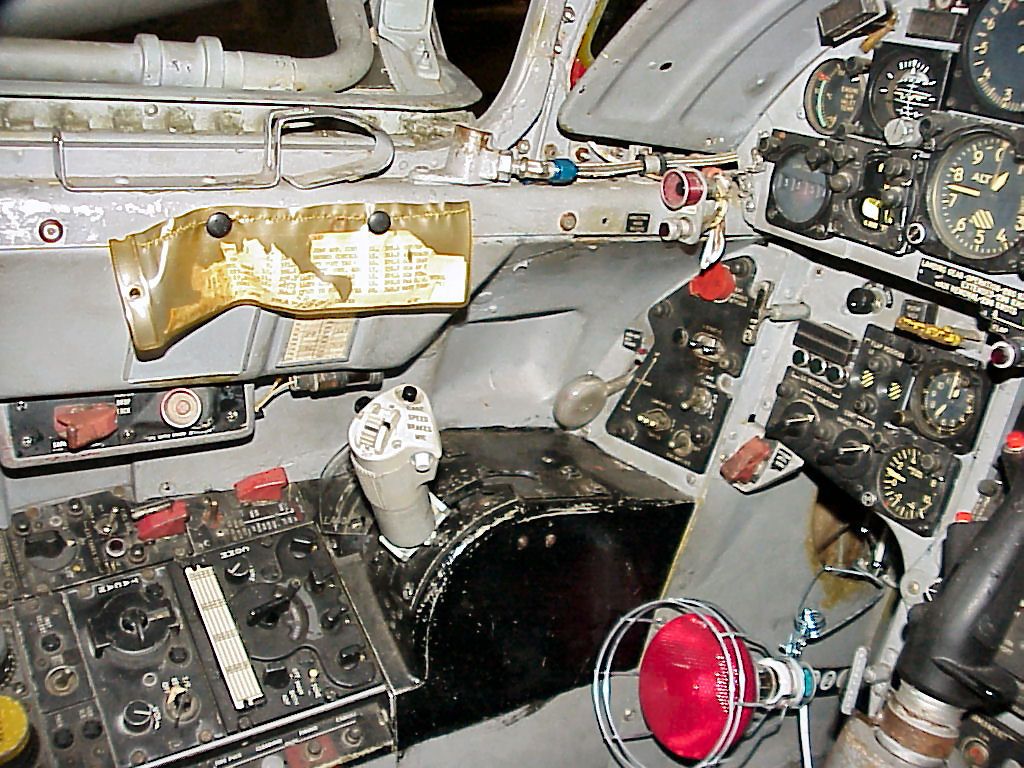
The second fret contains mainly parts for the walls of the side consoles and the inside of the hatch that was originally used for the downward ejection seat. The set doesn't provide the parts in such a way that you can dispense with the cockpit floor altogether. That would've been the most accurate as the F-104 never had a true cockpt floor. Somewhat like the F4U Corsair...
PreservedAC
In practice, between the stick, the foot boards and the sidewalls there wasn't much room, so it may not be too noticeable. But since you cannot show the model with it's seat removed, the parts for the inside of the lower hatch are somewhat of a waste of metal... I think that providing sidewalls that go no further than the imaginary floor is a missed opportunity, even if Eduard always claims "only to add detail, not to improve accuracy".
Look at Eduard's instructions to see what I mean.
Although I REALLY am a bit dissapointed about the floor issue, I still give this set a Highly Recommended as it provides enough other details that really enhance your F-104C Starfighter cockpit.
My thanks go to Eduard for providing us with the review sample.
-
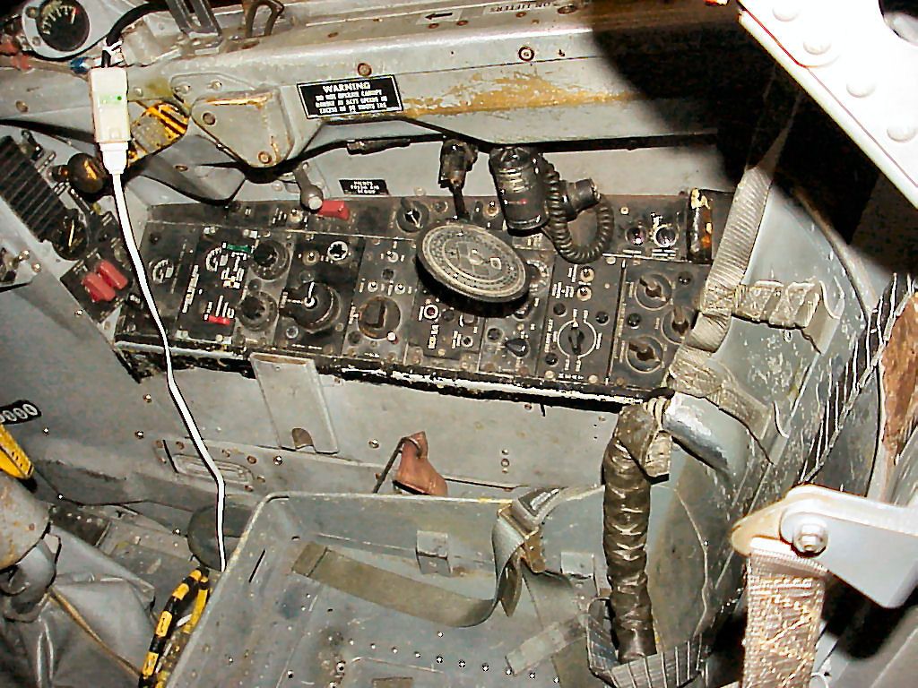
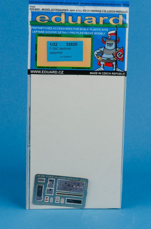
Eduard F-104C Electronic Equipment.
Product number 32 820.
Available from many online shops or directly from Eduard for €18,75
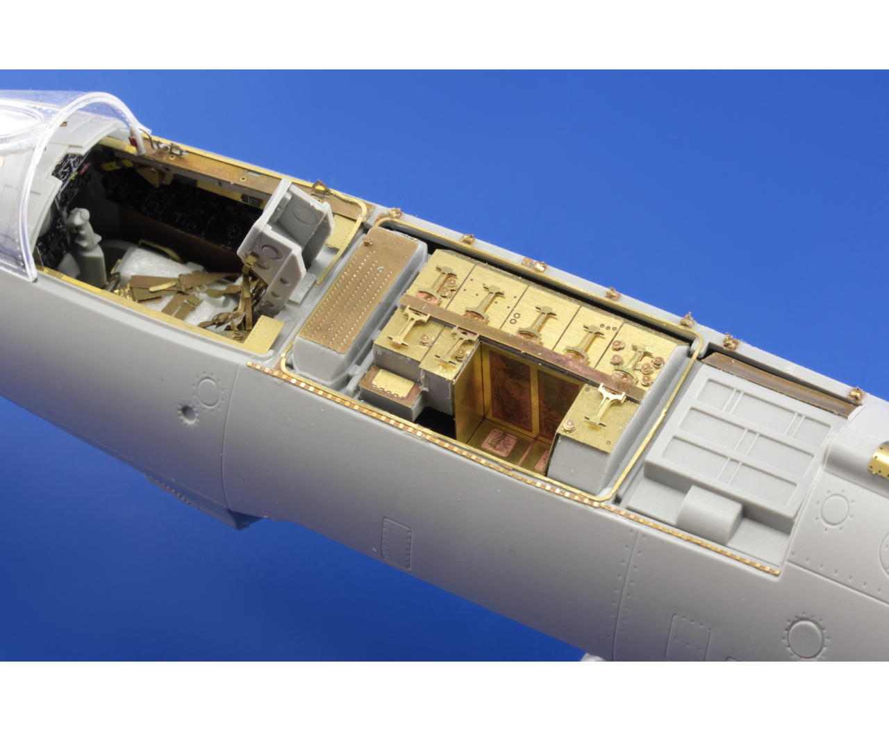
This is really quite an involved sit to detail the avionics bay behind the cockpit by adding detail and through the deletion of a couple of "F-104 Jeep Cans" add depth to the bay.
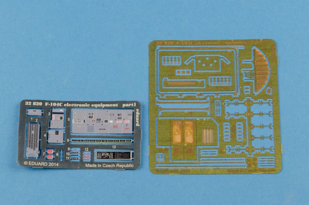
Those two frets look deceptively easy to use. You are required to cut away some of the moulded jeep boxes and build up part of the bay with PE parts. It looks to me that the end result can be quite stunning. Especially the detail parts that deal with the sills of the bay and the hatch will make a big impression, even if you would decide not to cut in the jeep cans. As the jeep cans were separate boxes that could be added and removed as the mission required, I hope that the single part 5 that makes up the sides and tops of 5 jeep cans doesn't detract from that "loose components look". I'm afraid I can't really answer that until I use this set on my F-104C...
The Eduard instructions will show you what has to be cut & sawn...
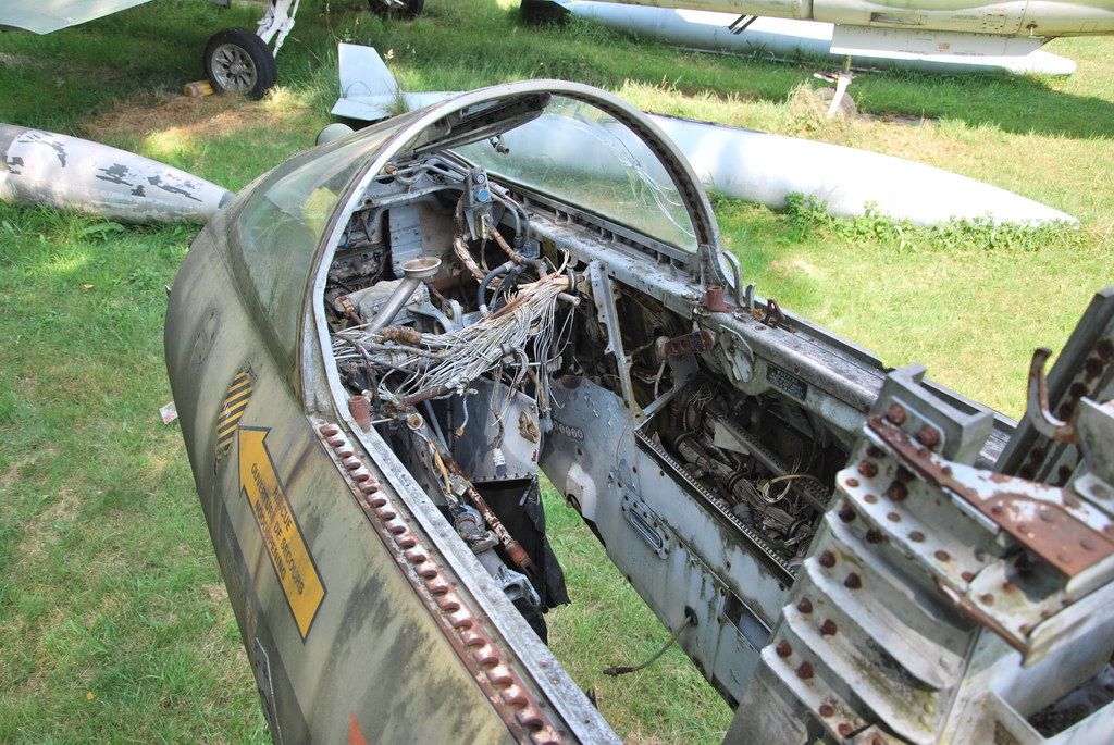
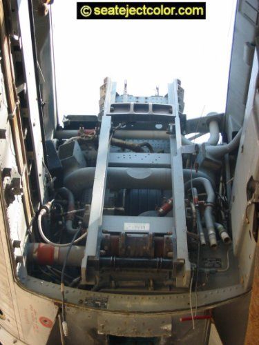
The jeep cans in an F-104G, compare with the contents of the set:
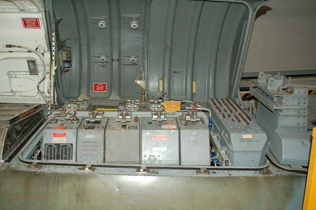
Pablo, flickr.com/photos/pabloaircraft
As for accuracy, I could find only 2 photos of the F-104C compartment, -B&W and quite small- in the Detail & Scale book. That aircraft has a different set of jeep cans installed, but that doesn't say anything. The DACO book "Uncovering the (T)F-104G Starfighter" by Danny Coremans and Peter Gordts show 3 F-104G's that all 3 have a different jeep can and circuit breaker configurations... I wouldn't be afraid to use this set for an F-104G too, to be honest! BTW, the big box in the aft compartment isn't an electronics box, it's the magazine for the 20mm ammunition. So, if you would decide to use this set for an early F-104A, RF-104G or CF-104, be sure not to show the magazine, but the equipment that the aircraft carried instead!
I would say Highly Recommended, but check out the instructions to decide if you want to put in the extra effort this set asks. For the right depth of the different jeep cans you may even have to separate part 5 into 5 different parts.
My thanks go to Eduard for supplying the review sample.

1/32 HK Models Mosquito B Mk.IV
in LSM 1/35 and Larger Work In Progress
Posted
Jeroen, looks superb! Although I have no photographic evidence, it may be that this aircraft flew with Medium Sea Grey spinners that had a white tip. Makes it look even prettier!
The Profimodeller stencils are indeed far more extensive than the kit ones. Sadly, some stencils contain spelling errors - although it's not unknown to see spelling mistakes on actual aircraft, too!
But that the 24 Volt socket is signed as a socked....? Small stencils where the locks for control surfaces have to be placed are labelled as looks, although these are small enough not to stand out too much. But if one knows about it.....