
James H
-
Posts
3,247 -
Joined
-
Last visited
Content Type
Profiles
Forums
Events
Gallery
Everything posted by James H
-

1:64 HMS Indefatigable (1794) - prototype for Vanguard Models
James H replied to James H's topic in Non LSM 'WIP
Not great photos, but I have been asked several times about the size of Indy compared to Amati's 1:64 Victory prototype, so here's a couple of photos for you. Remember that the angle of the first pic makes Indy look bigger than Vic. It isn't! That's why I did a photo of Indy sat on Vic's lower gun deck. -
1:64 HMS Indefatigable (1794) - prototype for Vanguard Models
James H replied to James H's topic in Non LSM 'WIP
Just for some info, Indy will be approx 880mm tall. Ok, onto business. The hull is now faired. This isn't really a task you can sit there with a piece of sandpaper and hope to achieve inner calm. Chris finally talked me into getting a palm sander (mouse), so I splashed out on a Black & Decker one. Even with this, fitted with an 80 grit pad, this job still took me a total of about 5 hours, along with the final task of wrapping some sandpaper around a 12 inch piece of thin ply to absolutely ensure the curves were right....plus the joyous task of blending those last bulkheads and fairing blocks into the keel. There is a lot of regular planking on Indy, but the inner core of the outer bulwarks are laser cut. So as not to stress out the forward bulwarks and those temporary gun port sections, these were first soaked and clamped in place. These were left for a full 24hrs to dry out and shrink back to their normal size. Pear has a hell of an expansion, even when soaked for 30 mins in hot water, so you really need to find a book to read, guitar to play, or TV to watch while this dries. Now that the parts are completely dry, I draw around the forward position of the bulwark so that I have my positions for the flow of the first plank that runs below the gun ports, and also the extent of the planks above this. It's important to know here that this pear part sits along the top of the gun ports on the main deck. The pear bulwark is now removed and the first 1.5mm thick lime strip laid along the bottom edge of the gun port sills, and along the lower line I've just drawn. On the prototype, each plank is 500mm long, and they meet up on the double thickness bulkhead #9. We're not yet sure if that will be the case on the final product. The back end of the same plank run is now installed. These planks are pinned until dry. If you pin all the way through, they will penetrate through the inner bulwarks, but that doesn't matter as any holes will be in the area covered by the spirketting. The pear bulwark sections are now temporarily clamped into position so the bottom edge runs along the top edge of the gun ports. You don't need top do this but I just considered that it was good insurance that the plank that runs directly underneath these pear parts, would be properly installed and a snug for in that area.It also gives you something to finally sit these parts onto later so you have a much better chance of both sides being exactly equal. Care is taken not to get any glue on those pear bulwarks. The spaces between the gun ports are now filled up with lime strip. This doesn't need to be neat at this stage. They'll be cleaned up later. A razor saw is now used to cut away the lime strip in the top row, that is partially obscuring the gun ports. The pear bulwarks can now be reinstated, but before this happens, you need to know a little bit about the side framing of the rear half of Indy. Not all of it will become a part of your finished project. When it comes to gluing the rear sections on first, the area in red here WILL NOT have any glue applied to it as that section will later be cut away. You can see the area with glue covers the the lower area just underneath the red area and for the rear section, it terminates at the point where the longitudinal strips were installed in sections. When you look at the model and my previous photos (without red marks), you can see that split in the strips, denoting the two areas. The rear bulwarks are now finally glued into position after some final measuring, ensuring both sides are in exactly the same position. This isn't too difficult now that this part sits upon that lime plank. Other factors also help too, such as the two rear gunport frames on the quarterdeck and the quarter gallery doorway. Just check at the back end to make sure things align with the stern timbers. Of course, you don't need to worry about gun port alignment on the rest of the quarterdeck gun ports as those frames will later be removed, as discussed. 2 inch clamps are very useful here to make sure the bulwark is squeezed into the hull curvature, as they can hook through the gun ports. The mid and fore pear bulkheads are now glued into place. And for the last part of this update, here's how she currently looks. Next job is to cover that lower real estate in lime planks. Remember, this is the same size as Agamemnon! Until next time.... -
1:64 HMS Indefatigable (1794) - prototype for Vanguard Models
James H replied to James H's topic in Non LSM 'WIP
Another update. Not too much to show this time, but there was a lot of work in terms of sanding and waiting for soaked parts to dry before gluing etc. Before I could proceed, I needed to sand the inner bulwarks. This isn't too bad of a job...just time consuming. Despite my pic, you're best rolling the hull onto its side on a towel, and applying pressure downwards when sanding. This is done until everything is nice and even. Each 1mm interior bulwark is split into four easy to manage sections. To lessen any load on the frames, so as not to cause any spread in them, all inner bulwark parts were soaked for 30 mins before clamping into place until dry. These were left 24hrs so they were entirely back to their normal size. Pear swells a lot in water, so it's vital you know, beyond doubt, that there's no swelling left. Once dry, all parts were carefully aligned to the port frames, glued into place, and clamped until set. Provision now needs to be made for the eventual deck beam positioning. This is done using some 2mm MDF frames which slot into the bulkhead beams, above the inner bulwarks. There are two per side. These fit with a nice, reassuring push, but at this stage I don't glue them. A good number of the 6mm pear deck beams and 5mm boat beams are now sotted/hooked over the MDF parts I just installed. This is done to check that the position of those MDF parts are absolutely in the right place. These beams are NOT glued in yet, obviously. At this point I've also reinstated the MDF temporary beams across the quarterdeck bulkheads. Again that's just to make sure every dimension is exactly as designed. Once happy with everything, the MDF deck beam mounts are brush glued into place. Lastly, the pear beams are removed and carefully put away somewhere safe. The temporary MDF beams remain in place to help me with the hull fairing, and that's the next job. That's all for now. -
1:64 HMS Indefatigable (1794) - prototype for Vanguard Models
James H replied to James H's topic in Non LSM 'WIP
Continuing today's update: Time to get rid of that blank section in the last bulkhead. That was there to protect the bulkhead while work was being done on it with shaping the stern. A gentle twisting removes this from the hull. Time for the stern timbers to be fitted. These slot across the rear two bulkheads, creating the correct angles for the parts. They also sit on the shaped stern upper block. First the inners, then the middles, followed by the outers. Some filler blocks are now added to the outside of the outer timbers, creating the rest of the platform and something to plank to also. Those fragile rear bulkhead ears are now bolstered with the addition of more longitudinal strips, all slotted to fit. The gap you see between some of them is to house the fore bulkhead screen. That's designed so you get zero gaps. You'll see that later in the build. Door frames are added from the captain's cabin to where the quarter galleries will eventually fit. Once dry, the inner horizontal parts of the frames are cut out. Part of bulkhead 18's ear is now cut out as this is the only one that would obstruct the gun port. That is sawn out and filed flush before the last gun port frames are glued in. To create a rigid structure for fairing, the rear of the hull has some temporary MDF sections that are held in place with pegs. These are totally solid and shouldn't come loose. And that is it for today. I'm whacked! -
1:64 HMS Indefatigable (1794) - prototype for Vanguard Models
James H replied to James H's topic in Non LSM 'WIP
Time for another Lego update. Next job was to bolster those bulkhead ears by adding the gun ports. As with Sphinx, these are built into the frame. The main gun deck longitudinal frames lock into the bulkheads and comprise two parts upper per side, and two parts lower. Lower in first of course. The vertical gun port frames now need to fit in. These are all specific, to suit the curve of hull. Each port has two verticals apart from #7, as that one uses the side of a bulkhead for the other vertical. The main gun deck ply layer is pre-engraved to help you with laying the planks. It's also supplied in halves, to make it easier to fit. Both deck halves are turned upside down and a strip of narrow tape is applied full length, and then the various openings cut out. The deck is then turned over and bent down the tape hinge before being glued into place. Deck edges lock into slots in the base of the bulkhead ears, so there's no problem with it popping up. It's just a case of making sure it's glued down across the deck beams and then weighted down while it dries. No need to pin anything here. -
1:64 HMS Indefatigable (1794) - prototype for Vanguard Models
James H replied to James H's topic in Non LSM 'WIP
Small update as I hated leaving it without a bow and stern from the last update 😁 First, the bow. The foremost 'timberheads' near the prow are pear inserts to the MDF former so there's lots of strength up front when later work is carried out. Bulkhead #1 is temporarily fitted to the hull and then the formers are fitted in. The reason for doing this on model is so I can get the innermost formers snug against the keel. All these parts are numbered and the relative slots on the bulkhead are numbered too. The assembly is now removed from the hull before the outer formers are set and the upper parts (35) are glued into place as seen here. Too stiffener pieces are also glued to the exposed side of the pear inserts. The assembly is now left to properly dry. A sanding block is now taken to the bow and the whole lot is sanded and shaped in readiness to fit to the hull. The back side of this also hooks onto bulkhead #2. When I was happy with this, it was glued to the hull. It's now the turn of the stern and fitting out the final bulkhead. As with the bow, this is fitted with a series of formers that are numbered in relation to the bulkhead slots. It's a no-brainer! This is now carefully sanded to shape. It will doubtless be refined later when it comes to fairing the hull. Once happy with it, it's glued onto the hull. Until later! -
1:64 HMS Indefatigable (1794) - prototype for Vanguard Models
James H replied to James H's topic in Non LSM 'WIP
This photo shows the standard ply engraved section for the lower deck. As I've said, you'll be hard pressed to see this stuff, unless you're an ant that's crawled in. But in case you are, or have that endoscope I mentioned, the detail is there in part. Here you see the ply engraved part along with the optional maple deck section which I have opted to use for this build. The deck section is now glued into place. Two, 2-part grates are now built and added. And of course, you'll need some steps down to the dinky orlop deck. These two beams are now added, again without glue. These two beams hole them firmly in place and are located with two pegs each, glued into the slots. And lastly for this update, a whole raft of deck beams are fitted between those two longitudinal parts. -
1:64 HMS Indefatigable (1794) - prototype for Vanguard Models
James H replied to James H's topic in Non LSM 'WIP
Work has now begun. First, the obligatory disposable cradle shot 😃 Indy certainly isn't short of bulkheads. There are 18 in total, with #9 midships being a double layer bulkhead. There are no bevel marks on Indy. They simply aren't needed for a kit of this level. Fairing will be an easy task. All bulkheads are 4mm MDF, as is the keel. The keel slots are numbered too so you get things in the right place. Indy is a strange build in that practically all you see in this update, with the exception of lower deck/orlop detail, can be assembled initially with no glue. All bulkheads you see being added here are put into position as such. Now this is where the magic happens. Once all bulkheads (apart from #1, #2, #15, #16, #17 and #18 because they aren't needed yet) are slotted into their position, these keel doublers are added, bulking out the keel to 12mm! What these do is to hold the bulkheads in their exact position. while pegs slot through the holes to lock everything into position. Zero glue apart from the pegs themselves. Bulkheads #15, #16 and #17 are now added because the fairing parts will now lock them into position as with the other bulkheads. Bulkheads #1 and #2 are now fitted, but NO GLUE at this time. The fairing patterns are now added. You will see these as No.s 37, 38 and 39. Like the others, these are pegged into place. Is there an orlop deck? There certainly is. This is it 😆 Nothing more is needed. In fact, you'll probably not even see this without an endoscope. This part is glued into place. The 3mm MDF sub deck is now fitted. Care needs to be taken around the bulkhead ears. You should have no problem....just don't go charging in. To fit this, I ran some Titebond down the 12mm wide keel centreline. Nothing here needed to be weighted down or pinned. It fit perfectly with a reassuring push. Pegs are now pushed into position which give a further aid to making sure everything is level. At this stage, things look like this: -
1:64 HMS Indefatigable (1794) - prototype for Vanguard Models
James H replied to James H's topic in Non LSM 'WIP
This photo gives a rough idea of the size of Indefatigable to Amati's 1:64 Victory. -
1:64 HMS Indefatigable (1794) - prototype for Vanguard Models
James H replied to James H's topic in Non LSM 'WIP
Continued. I've grouped most of these photos into thickness of sheet, and there are a lot of various thicknesses with multiple sheets for them. You can see the tabbed gun carts here too. Those tabs are on the forward 'bulkhead', closest to the inner bulwarks. You're going to have to make FIVE ship's boats for this one! Inner bulwarks are split into three sections to cover the entire length. There will also be doorways from the cabin into the quarter galleries. 3D printed stuff, like belfry, anchors etc. and I do see some copper tape there too. Quirks of prototyping. Various cabin floor sections. LOTS of strip too. Decals for name and depth markings. Also, there is no white edge on that text. It's merely the light catching the ink edging! I have checked. -
1:64 HMS Indefatigable (1794) - prototype for Vanguard Models
James H replied to James H's topic in Non LSM 'WIP
Time for a quick update. This will be the last one before work starts very shortly. I'm making this update over TWO posts due to number of pics. These are just camera photos and won't represent anything you see in the manual. Indy turned up with UPS this morning, and the box is large and heavy. In fact, the box isn't large enough yet as the masting, rigging, manual and plans also need to be included, as well as PE etc. The box was packed out as it was. This one took up two seats on my sofa. Take a look through and you'll notice some little things here and there. One of those is that the main gun deck carriages are tabbed so they slot into the deck and can't be knocked free later in the build. This is only an optional feature as the modeller can, if they wish, plank over the tab slots and remove the tab from the carriage. That would be up to the individual but this is a perfectly good solution that will be invisible when implemented. If also means the guns will be perfectly spaced too and the barrels therefore evenly protrude from the hull. Those barrels will also be fitted after the hull is painted, so attaching them later won't dislodge a gun cart. This is the engraved maple deck which won't be included as standard, unlike the other kits. This kit will have traditional planks for the deck, but it is quite likely that this option will be provided on release. If that happens, then the gun carriage location slots aren't likely to be there, and you'll simply open them up if you want use that kit feature. Oh, these parts are BIG!! My cutting mat is in 1cm squares, as a guide. Not fantastically clear here, but the ply sub decks are engraved with planks. This isn't the finish. It's designed to give you a template onto which to lay the kit planks. That will save the modeller having to mark up stuff themselves. -
1:64 HMS Indefatigable (1794) - prototype for Vanguard Models
James H posted a topic in Non LSM 'WIP
A little history (edited from wiki!) HMS Indefatigable was one of the Ardent-class 64-gun third-rate ships-of-the-line designed by Sir Thomas Slade in 1761 for the Royal Navy. She was built as a ship-of-the-line, but most of her active service took place after her conversion to a 44-gun razee frigate. She had a long career under several distinguished commanders, serving throughout the French Revolutionary Wars and the Napoleonic Wars. She took some 27 prizes, alone or in company, and the Admiralty authorised the issue of four clasps to the Naval General Service Medal in 1847 to any surviving members of her crews from the respective actions. Indefatigable was ordered on 3 August 1780 (long after Slade's death), and her keel was laid down in May 1781 at the Bucklers Hard shipyard in Hampshire owned by Henry Adams. She was launched in early July 178, and completed from 11 July to 13 September of that year at Portsmouth Dockyard as a 64-gun two-decked third rate for the Royal Navy. She had cost £25,210 4s 5d to build; her total initial cost including fitting out and coppering was £36,154 18s 7d (around £6.6m in today's money). By that time, she was already outmoded for the role of a ship of the line as the French only built the more powerful 74-gun ships, and she was never commissioned in that role. She was broken up in 1816. The kit This is quite literally hot off the press with regards to what you see here. Indefatigable is being represented in this new kit as the razée, and quite rightly so. I do have a lot of affection for the stuff built at Bucklers Hard, having visited there a couple of times myself. It's a beautifully tranquil place in England's New Forest, which really does betray the hive of activity it used to be. It even has the original shipwrights houses and the pub there, as part of the tour. Just to think, Indefatigable was definitely built in one of these two slips, as was Agamemnon etc. I took these photos a couple of years ago. This is very stuff for Indefatigable, as all I currently have are the cannon, carronades, and also the cutter. It will also become very obvious that when building these models, I never do anything in chronological order as seen in the manual. I work on whatever Chris has completed and sends over to me, with other work infilling between main tasks. I try to waste as little time as possible in order to keep to fairly tight release schedules. For the first time you'll see me work on stuff like this before the big hitters are sent to me. Even then, I will feed back with my findings and things will possibly be changed to reflect my own build. Not too much to see at the moment, and work won't start proper for a week or so, so keep checking in to see if things have progressed. Here's the two sheets of 2mm pear which contain the gun carts... I also have three bags of guns. These are: 12-pound long 24-pound long 42-pound carronades I do need to wash these guns in some isopropyl, especially the carronades as the initial washing left then with tissue debris on them. Also, the carronade carriages will also have 3d-printed wheels! Indefatigable will have many of the design traits of Sphinx, but this time incorporate more traditional planking around the upper bulwarks and gun ports etc. Indy will also feature a traditionally planked deck too. Here are the parts for the cutter: -
I really don't know what to say about the engineering choices on this kit, except that you'd think ZM would learn a little from previous kits which were over-fussy to assemble, going right back to the dog turd that's the P-51D. I really, really was thinking about the forthcoming Henschel Hs 129B-3, but don't know if I should be spending hard-earned cash at a time like this. Kudos in cracking on with this build.
- 89 replies
-
- 6
-

-

-
- zoukei-mura
- 109
- (and 1 more)
-
This is something I just can't replicate. Have you tried a different browser?
-
I just can't seem to replicate this. Try to send me the same image in a PM.
-
Sort of reminds me of the Trump Avenger. That was one I always wanted to build, presumably designed by their 'A-Team' who did the Me 262.
-
The site PHP was updated yesterday but to a version incompatible, so I've fixed it. See if that's ok.
-

-
Hi Laurent, You can just click the 'forgot pass' and reset it yourself.
- 1 reply
-
- 2
-
-
The banning isn't about the posts that were removed from that topic. It's about this shitshow of a topic that the guy started.
-
When someone is openly attacked in a topic like this, using puerile and immature crap, the poster does not deserve to be a member of this forum, irrespective of the circumstances that led to him posting it.
-
In fact, fuck it. You're gone.
-
It must be me then who has their 'baby pants' on then? It was me who removed those two unwarranted posts (identical) from a build log. Am I elitist? If you have a problem, take it up with me, that's if you can discuss without using insults. If it's the latter, you're history here.
-
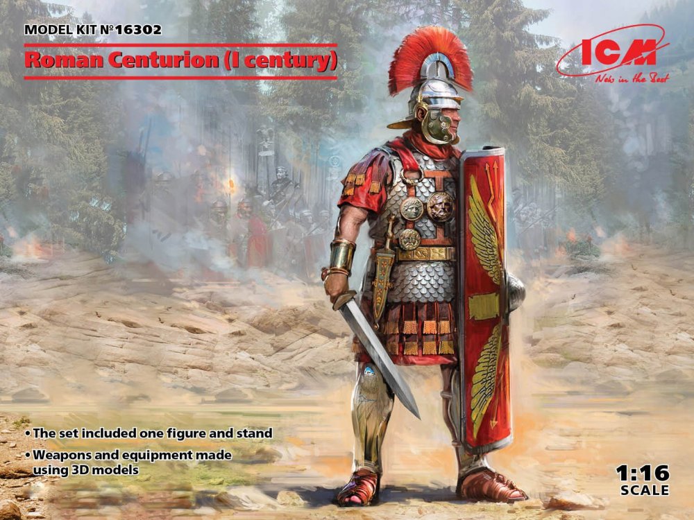
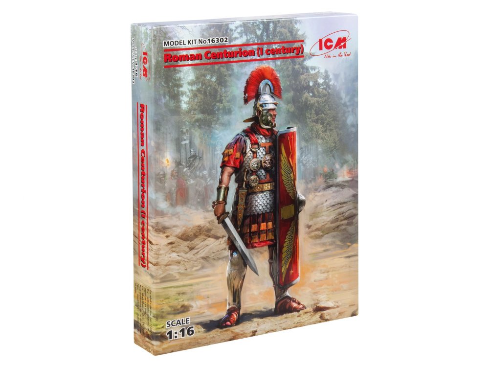
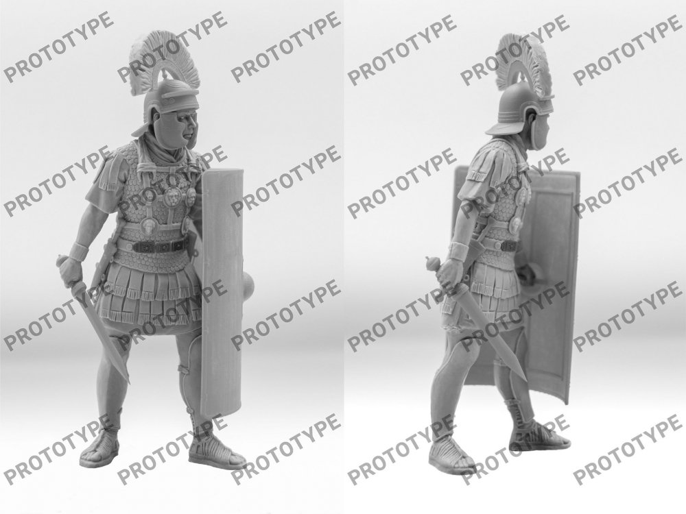
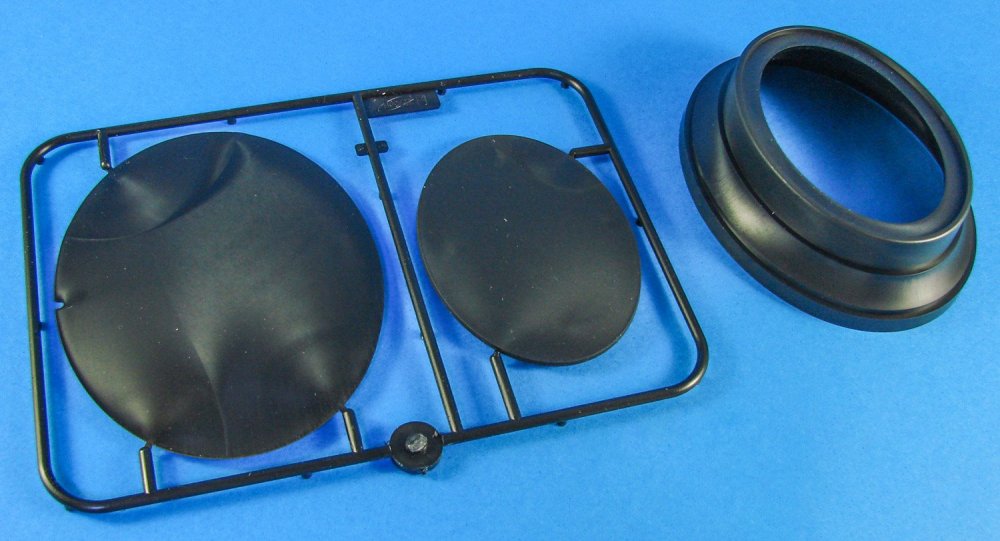
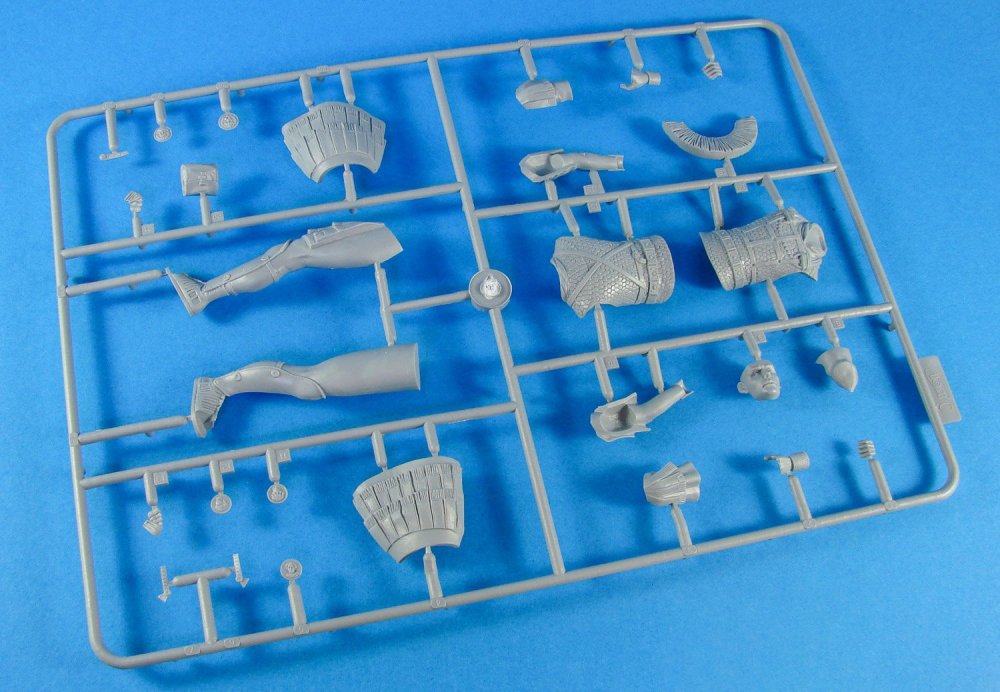
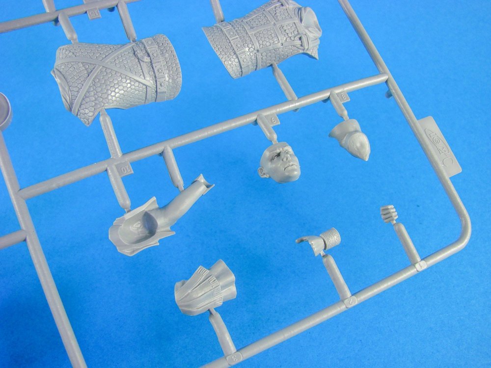
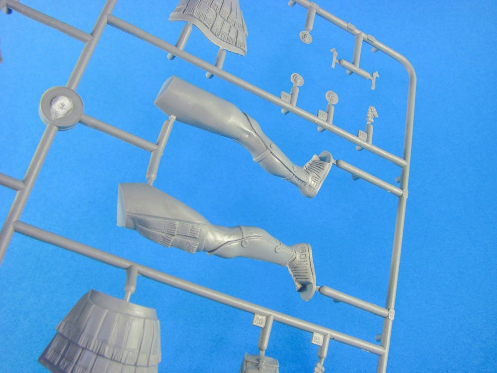
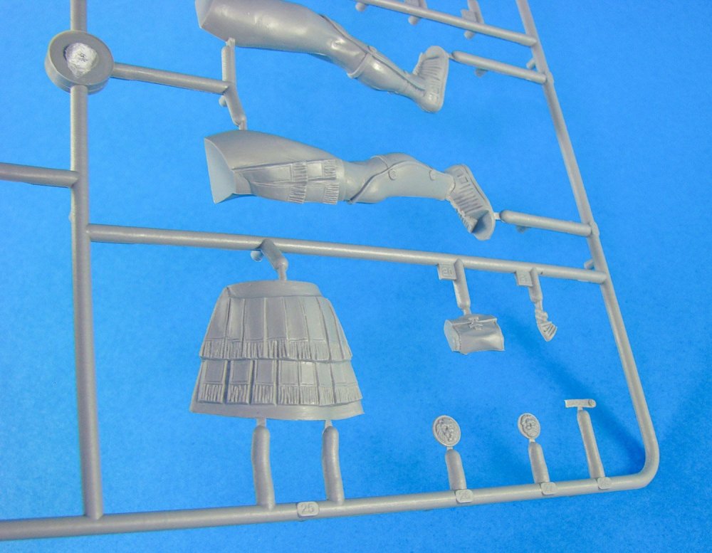
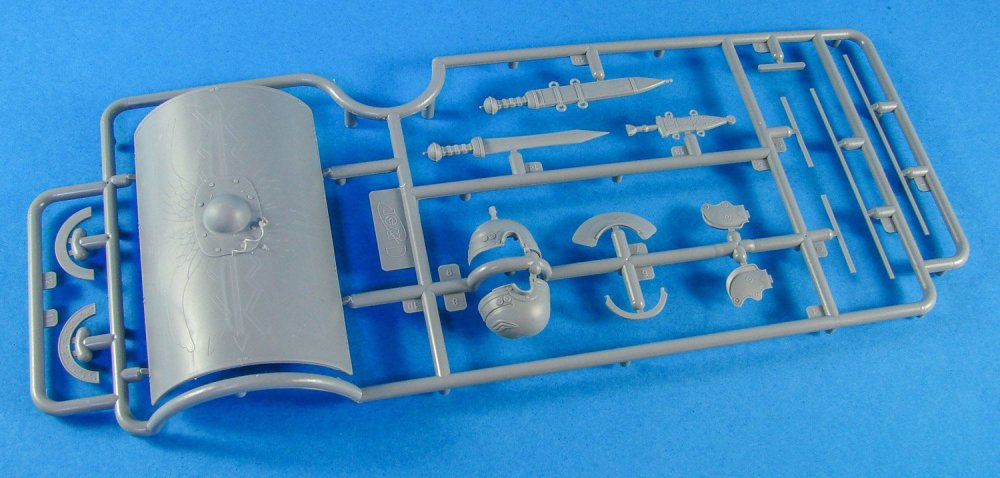
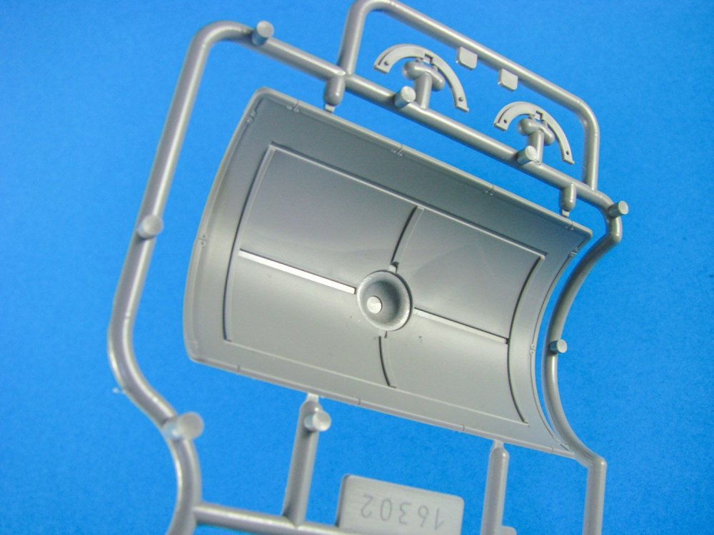
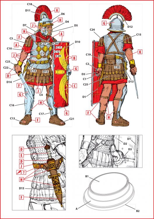
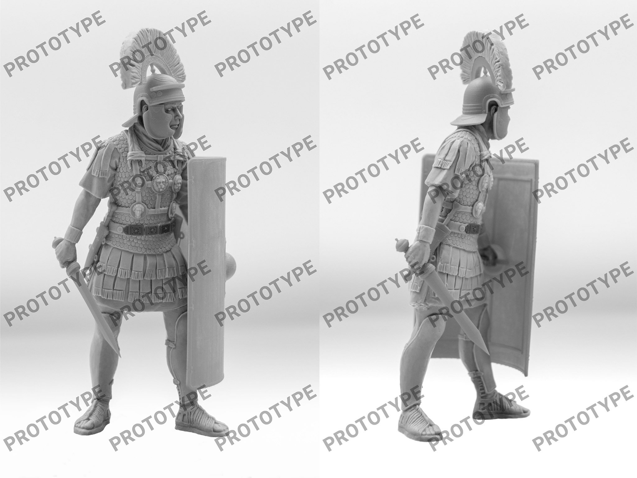
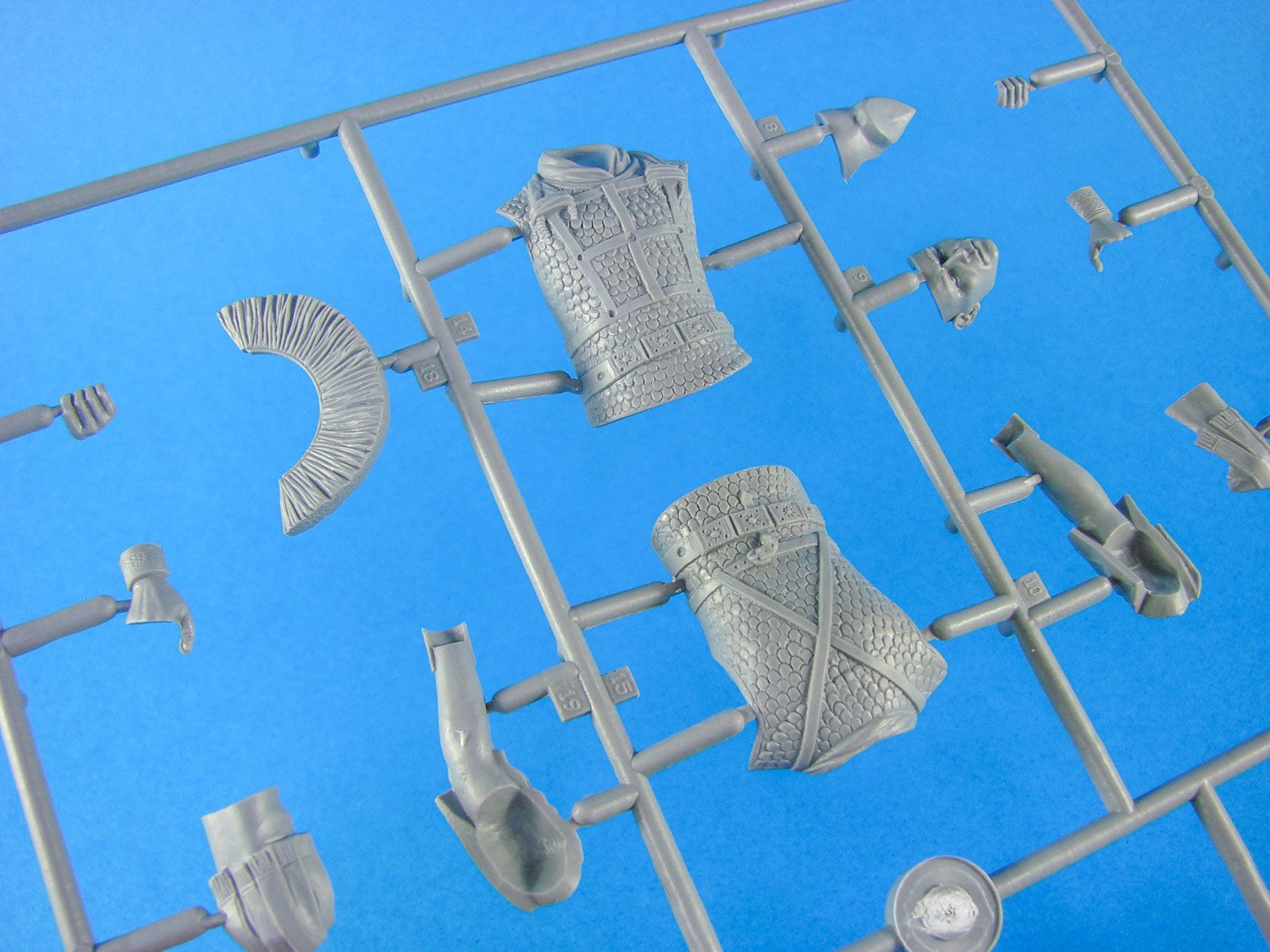
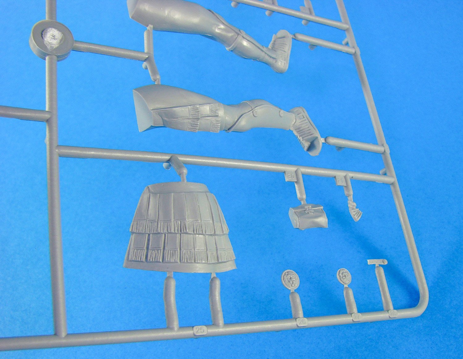
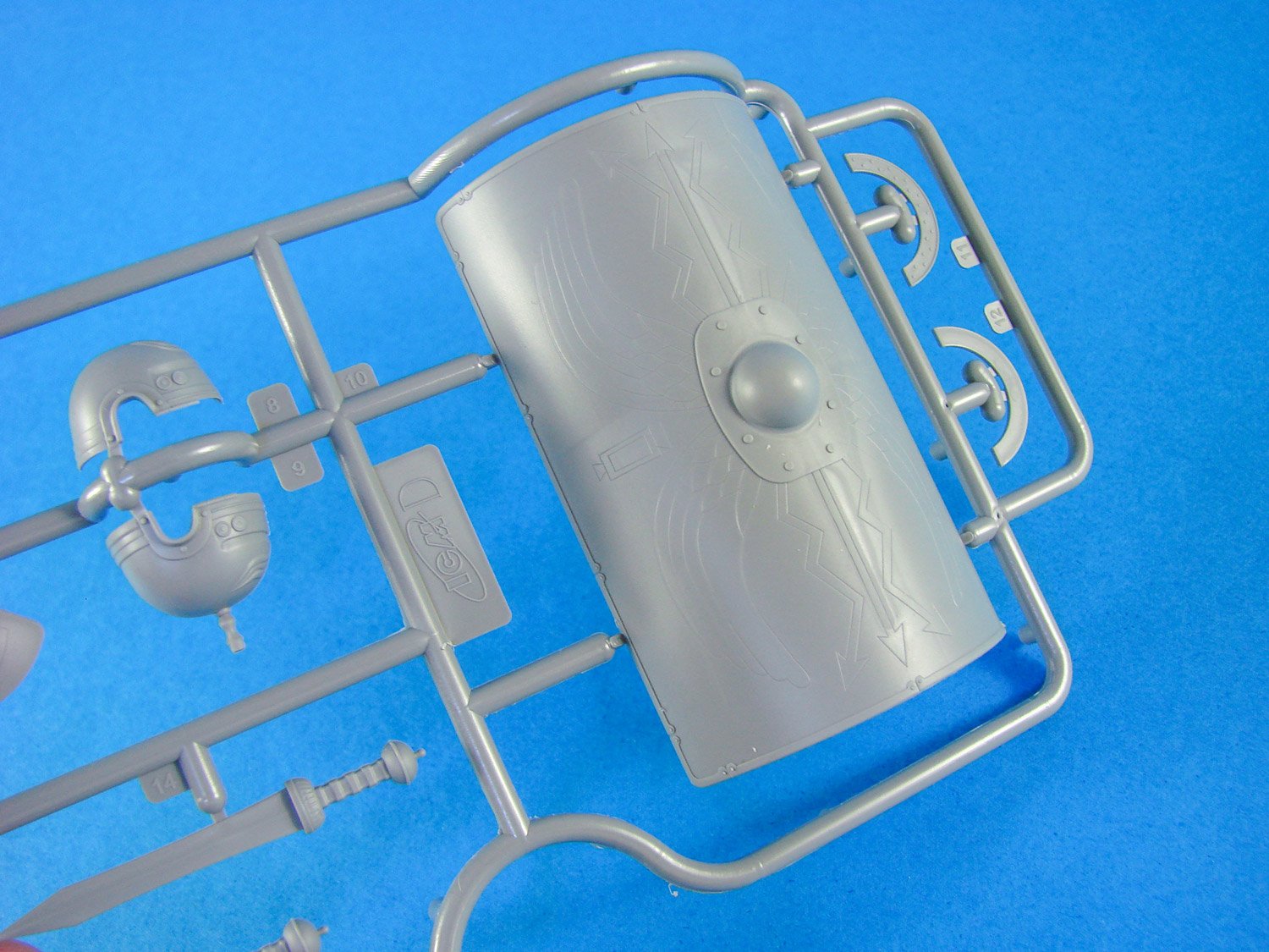
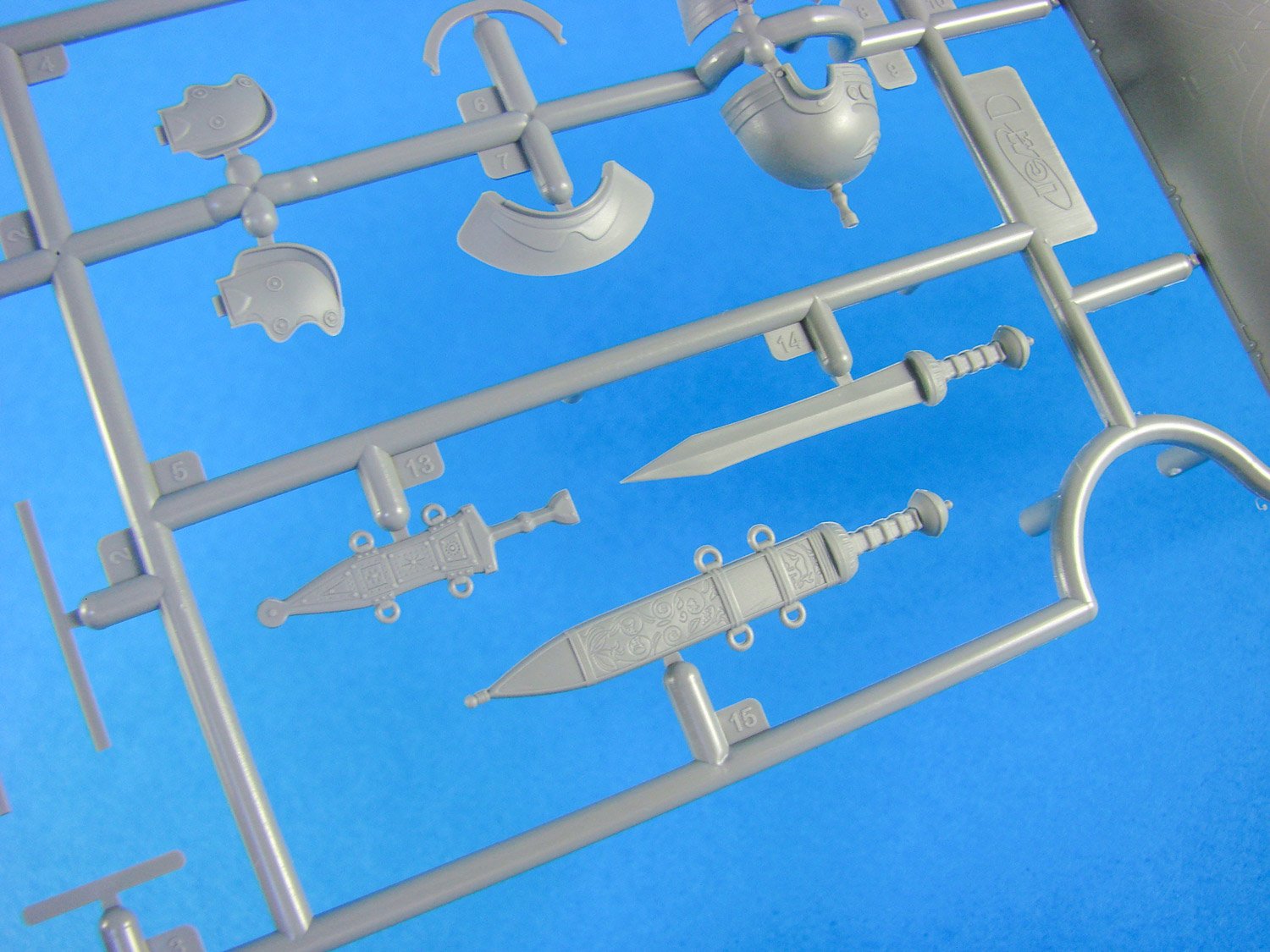
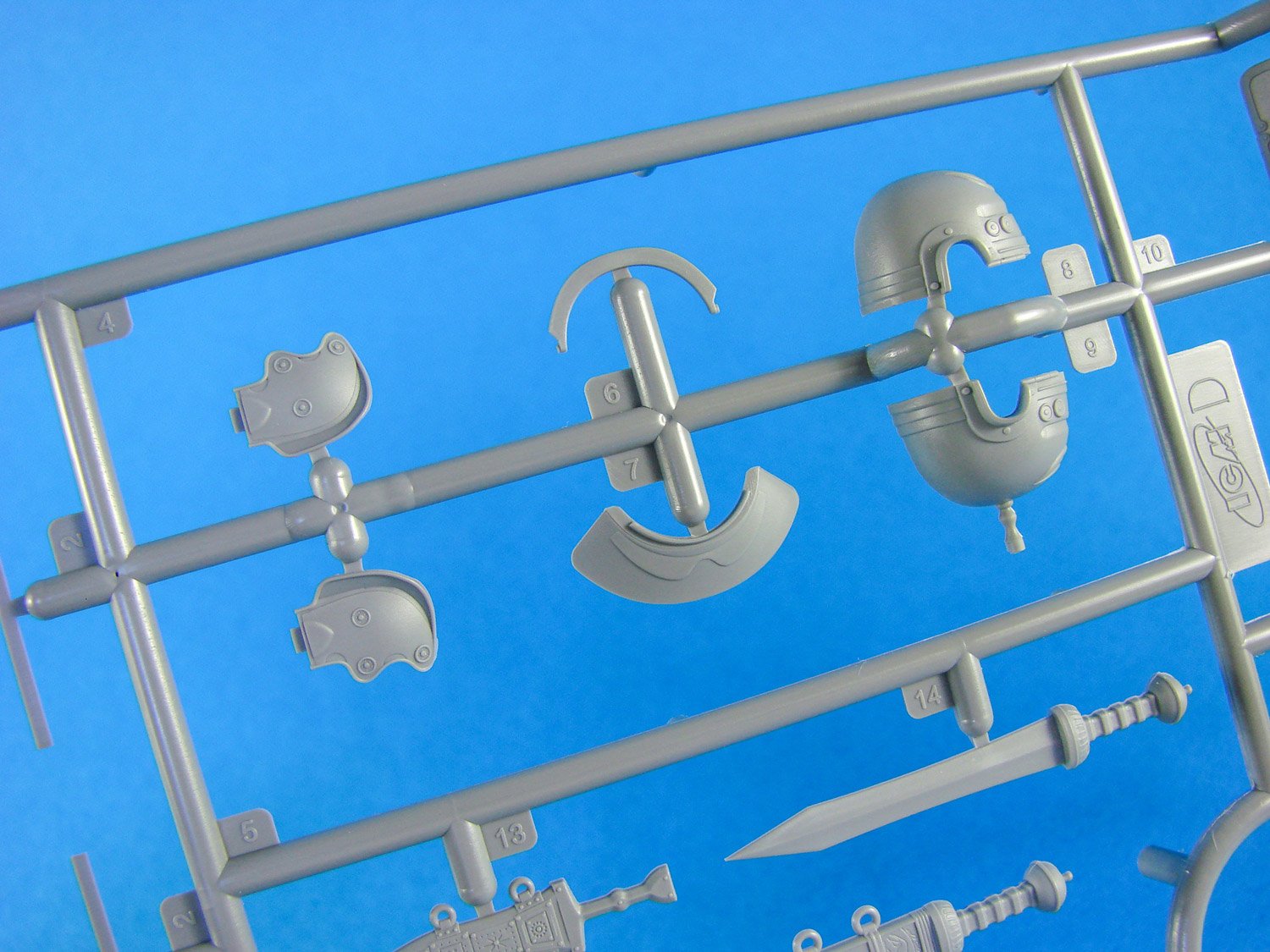
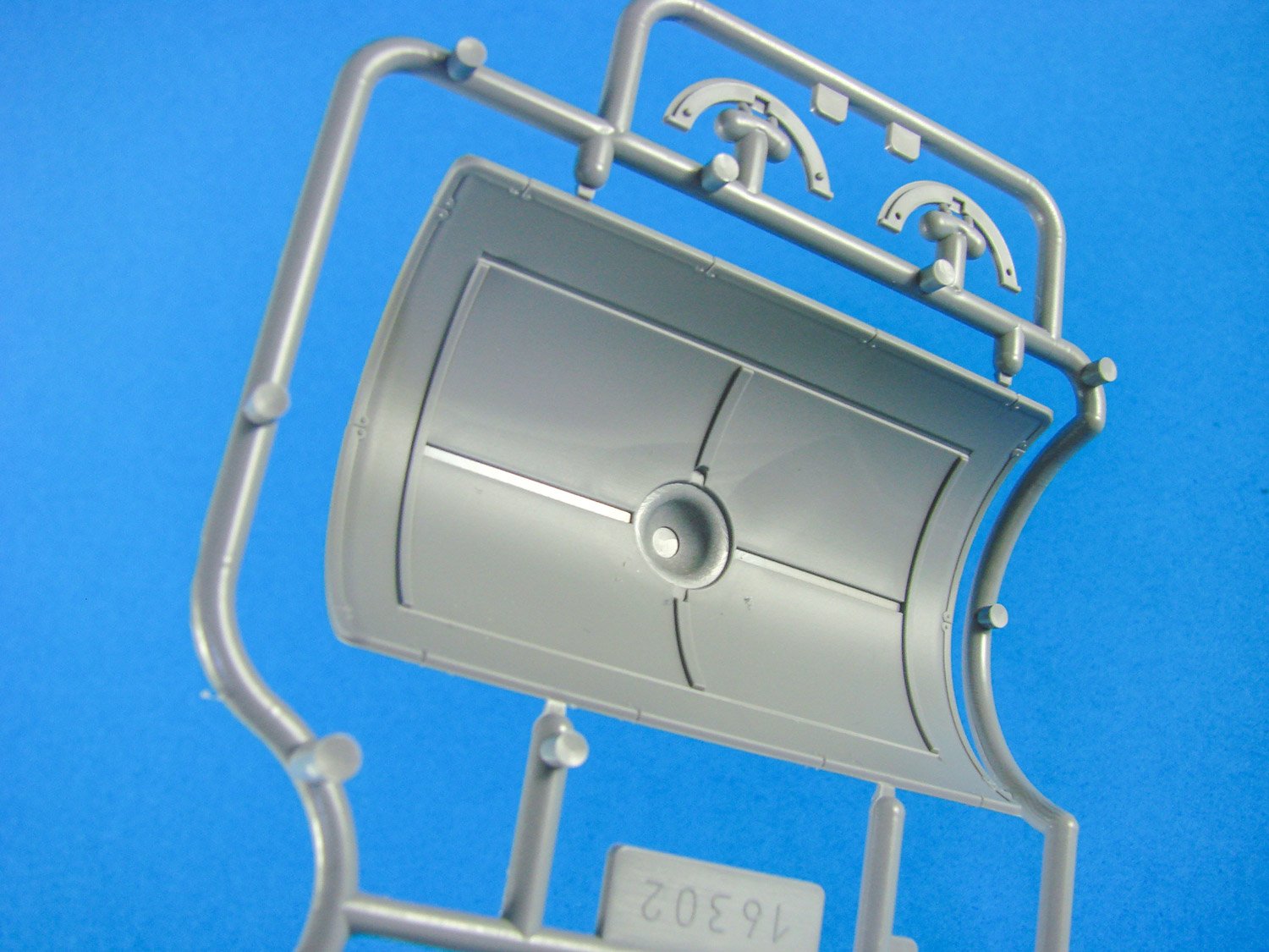
1:16 Roman Centurion (1st Century AD) ICM Catalogue # 16302 In the Roman infantry, centurions commanded a centuria or "century". During the Mid-Republic these centuries were grouped in pairs to make up a maniple, each century consisting of 30 - 60 men. After the Marian reforms a century typically composed of around 80 men, with six such centuries forming a legionary cohort. Later, generals and emperors further manipulated these numbers with double and half-strength units. Julius Caesar, for instance, made the first cohort of five double strength centuries. Centurions also received a much higher rate of pay than the average legionary. Veteran legionaries often worked as tenants of their former centurions. The kit Something a little different for LSM in that we don’t usually look at figures, and especially 1:16. This is one of two releases from Ukrainian company, ICM, that we’ll look at over the next week. The approach for this is quite simplistic in that while it’s generally easy to gauge an armour or aircraft kit, you really need to be something of a buff on military antiquity to judge how authentic the dress of a Roman or a Viking, for instance. This review will simply look at what’s in the box and the features. We’ll have to trust ICM on how much research has gone into the various items of dress. When I was a kid, I used to build the large-scale Airfix historical figures, and I loved the artwork on these. ICM’s box illustrations are certainly next generation in terms of depiction, and the boxes are certainly sturdier with that glossy lid tightly sitting on top of a whole box with a tabbed lid. All parts to build the Roman Centurion figure itself, are provided on just two sprues of light grey styrene. Another sprue contains the upper and lower base ‘lids/caps’, and a single part is the base itself. The oval base parts are moulded in black styrene. All plastic parts are provided in the same cellophane sleeve. No PE parts are included/needed with this release, and that is very typical of ICM kits. Of note are the instructions which simply depict the competed figure from front and rear, with the part numbers pointing to specific locations, and of course, the illustrations are in colour, so they double as your painting guide. Supplementary illustrations are supplied which show details for the Gladius (sword) and the Scutum (shield) handle. You can depict the sword in its scabbard or in the soldier’s hand. To depict with the soldier holding the Gladius, you need to remove the handle from the one mounted to the belt, and then try to hollow out the scabbard a little to make it convincing. A complete Gladius part can then be used to fit into the Centurion’s hand. The figure itself is quite easy to build, comprising around 49 parts, with a completed height of about 110mm. Whilst the upper and lower torso comprise a front and rear part each, the legs and arms (with exception of shoulder area and hands) are moulded as single pieces onto which the various parts of soldierly equipment will fit. Sprue B generally concerns the limbs, torso and head of the soldier (although not exclusively so), while Sprue D is for equipment and also the multipart Galea (helmet) with its famous brush top and cheek armour. The shield is generally moulded as a large, single part, but with some frames that need fitting to the rear, as well as the handle. All moulding is superbly executed, and whilst there will still be minimal seam removal, ICM have made a very nice job of not needing to add lots of supplementary stuff, such as the old styrene belts that we saw on the Airfix kits of yore. Conclusion It’s kits like these that really make me wish I could figure paint, as well as the 1:6 Eivor figure (Assassin’s Creed) that I have. The assembly of this ICM kit is nice and easy, and I don’t doubt whatsoever that the resulting figure really will look every bit the centurion he is, and with plenty of detail to keep the modeller and viewer captivated for a good while. Moulding quality is first rate too, as is always the case (IMHO) with ICM. Definitely a kit to get if historical figures interest you at all, and one that also retails for only around £20!