

ThomasProbert
-
Posts
410 -
Joined
-
Last visited
Content Type
Profiles
Forums
Events
Gallery
Everything posted by ThomasProbert
-
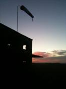
 Evening all I've dusted this off in time for a trip to Telford and decided to tackle the rudders over the last couple of weeks. You'll have to excuse the terrible photography as I haven't had the time to get the proper camera set up so I've been snapping away with my camera phone in the dark winter evenings... I carefully removed the fins from the stabilsers and using the set of plans I have, cut the shape of the rudder from plastic card. As the real thing is an aerofoil shape, I cut what would become the leading edges from sprue, and mated these to the rudder hinge line: Next up was to add some thicker plastic card to the forward third of the rudders to aid with the thicker forward part of the structure: The thicker forward sections and aerofoil shape were then made up and blended together with filler: They were then primed with filler-primer, sanded sooth with some micromesh, and then I scribed the basic panel detail on to them. The riveting will have to wait as I can't find my riveting tool anywhere at the moment: The rudders now fit nice and snugly to the fins themselves, which have now been reattached to the stabilisers: And here she is sitting pretty on the kitchen table and ready for a trip to Telford next weekend: As you can see I have also started playing around with the propellers, but more of that next time: I'll hopefully catch some of you at the Nationals - the Shackleton will be on IPMS West Kent so do pop over and say hello! Tom
- 185 replies
-
- 7
-

-
- Scratchbuild
- 1/32nd scale
- (and 1 more)
-
The decals were nice and thin and responded to decal softeners well. The upper wing roundals are slightly out of centre however, and there's a thin white 'shadow' around them which needs careful trimming before applying. Other than that, no problems.
-
Evening all The latest off the bench is Revell's new 1/32nd Spitfire MkIXc, which as I'm sure you know follows their release from a few years back of a Spitfire MkII and thus the breakdown of the kits is almost identical. This was a very pleasurable build and it went together relatively trouble free; the only filling needed was as the wing root fairings where the moulding was slightly short - I've seen this on many other builds and know it wasn't just my kit which has this issue. The simple solution is to add a small plastic card shim to each fairing and smooth it in with Milliput and a wet finger, and the problem is solved in under 10 minutes. At £25 I thought it fantastic value for money and will definitely be purchasing a few more. Decals for this one came from Xtradecal as the code-letters were off colour-wise on the Revell sheet. Paints were from the Xtracolour enamel range and it was finished with a coat of Humrol Matt varnish. Supermarine Spitfire McIXc, 132 Squadron, RAF Detling, November 1943: And alongside the MkIIa which I completed earlier in the year: Let's hope Revell keep giving us 1/32nd Spitfires at such reasonable prices - and roll on that P-51D! Tom
- 10 replies
-
- 2
-
-
- revell
- 1/32nd scale
- (and 1 more)
-
Afternoon all With the school holidays upon us and me entering retirement for the summer, I thought it time to get this project back on to the bench... As you can see, it doesn't fit all that well! I'd got to the stage of completing one outboard engine nacelle, so decided to get the other one done. This began by adding a series of strips (or planks) cut from plastic card and slowly adding them to the framework of the nacelle I'd made earlier: These were then built up over a couple of evenings until the basic shape of the nacelle was formed: With the glue allowed to harden for a week, I then coated the nacelle in a generous helping of car body filler: This was then sanded back and a coat of filler-primer applied, before this too was then sanded and polished to leave a beautifully smooth finish to the nacelle: After a serious sanding session, some light refreshment is called for I wasn't completely happy with the leading edges of the wings, so I also took the opportunity to re-profile them: I then primed and polished up the 3D printed 'power-eggs' and test fitted them to the firewalls - thankfully my careful measuring and planning paid off, and although they're not quite a Tamiya fit, they fitted pretty well: After the power-eggs were glued to the firewalls, it was a simple job to blend them in with filler and then give the wings a primer coat of grey - here the engine fronts are just taped in place as I still need to make the radiators and oil coolers before the fronts can be permanently attached: And so now a major milestone has been reached, about 18 months after starting this build, and the airframe is now complete: Underside: And here she is with a 1/72nd scale Revell Shackleton as a useful size comparison: So now I can concentrate on the detailing of the model - the cockpit and flightdeck may well be the next task as the upper fuselage still needs blending in. The extreme rear of the fuselage needs some tweaks too, but the main construction is now over and I'm pleased to have reached this point in the project - it's all down hill from now on! All the best, Tom
- 185 replies
-
- 7
-
-
- Scratchbuild
- 1/32nd scale
- (and 1 more)
-
Fantastic as always, Cees. Good to see the Manchester getting some bench-time. Tom
-
Evening all It's been a while since any kind of update on this project, but life and a general lack of motivation for it has got in the way over the last few months. However, I have been doing a bit of work on the outboard engine nacelles... The first task was to establish exactly where the outer engines were on the outer wing sections. I used a combination of my plans as well as scaling up the Airfix 1/72nd scale kit's measurements, and then made the firewalls from 1.5mm plastic card - these were stuck to a 'spine' which was cut to the profile of the nacelle which was in turn stuck to the underside of the wing. Confused? May be the following pictures will explain in better... Here are the firewalls in position on the leading edges of the wing: With the firewall and spine on the correct position, I could then begin to build up the basic shape of the nacelle with bulkheads (or formers) which again were checked against the plans I have as well as the Airfix kit to ensure the shape was correct: With the shape of the nacelle sorted, I then began planking the formers with 2-3mm wide strips of plastic card: The extreme rear of the nacelle has a too-steep profile for the planks, so this was made from Milliput and wet-sanded to shape without too much of a headache: And now we have an outboard engine nacelle completed: As you can see from the pictures, the surface is far from smooth. This won't be a problem though, as when the glue is properly cured (and thus there's no more movement in the plastic as it dries) it'll get a coat of car body filler and a thorough sanding, before a few coats of filler primer will be sprayed on to finish the job. Now one nacelle is done, I've got to get cracking with the other. The thought of cutting a load more planks doesn't instill me with joy however, but I keep telling myself it's the last of the main structural work on this project, and then it can be the fun detailing of the airframe. Until next time, Tom
- 185 replies
-
- 7
-
-
- Scratchbuild
- 1/32nd scale
- (and 1 more)
-
I picked up this long out of production single-seat 1/32nd MiG-29A cheap recently, and fancied doing a Polish version so also ordered a set of Decals from Techmod. I built this more or less out of the box, but did close the upper air intakes with plastic card, made some FOD guards for the exhausts and intakes, and added a seat belt set from Eduard, but kept the cockpit closed as it's fairly basic for this scale. Paints were from Xtracolour with varnish coming from Humbrol. I thought about coating it in gloss, as the Polish MiG-29s are very shiny and clean, but decided to do more of a satin coat for a better scale effect. The Revell kit is actually a MiG-29A version, but after doing a little research the differences between that and the G version very mainly internal so I could get away with it without too many problems. MiG-29G, Polish Air Force, 41st Tactical Fighter Squadron, Baltic Air Policing, 2012. With the new Trumpeter kit hitting the shelves, no doubt a few more of these will be sold off - hopefully I can snap another one up at some point. Tom
-
Still not finished yet, Cees? All joking aside, it's good to see some progress again. I'm sure you're like me and pick up long term projects like this as and when the mood takes. Slow and steady wins the race! Tom
-
Thanks for the pictures, Cees. I've got this kit on order and am very much looking forward to it being delivered so I can get cracking. I recently built the MkII and loved it - I'm sure the MkIX will be the same. For 30 of my finest English Pounds you can't go wrong really! Tom
-
Cheers, chaps! And yes, she's getting rather tricky to handle. Notice both fins are off as one took an unscheduled encounter with the wall adjacent to the bench, and thus I removed the other to protect it whilst there's still sanding and filling to do...
-
Evening everyone Not a lot of progress to report on the big Shackleton project, but work has been going on, albeit at a glacial pace... I've been getting the wing surfaces sorted, as after the outer wings were attached a coat of filler-primer revealed a multitude of sins to be sorted. The original plastic of the Lancaster kit was quite bumpy from the start, and the rather rudimentary panel detailing needed to go, too. So, the pictures you see below are the results of three coats of filler-primer that have now been sanded back and polished, to leave me with a lovely and smooth surface for the final priming: I've also begun the process of marking out the position of the outboard nacelles in preparation to make those: Have I said before that this model is rather large? Here's a 1/32nd Spitfire snuggled up and shows the massive span of this thing - it's not far short of the 1/32nd B-29 I did a few years back: Not the most enthralling of updates, but I wanted to assure you that this project is still ticking along slowly... On a final note, does anyone know of a good source of plans for the radome set-up on the AEW2? I'm going to redo my earlier one and need a lower, side, front and rear profile of the 'dome itself is anyone knows of a good set of drawings? Until next time, Tom
- 185 replies
-
- 7
-
-
- Scratchbuild
- 1/32nd scale
- (and 1 more)
-
I fancied a quick and easy project and seeing Spitfires overhead daily during the summer months (I'm under the approach to Biggin Hill) I didn't need much inspiration to dig this one out of the attic This model simply fell together and was an absolute joy - construction of the main airframe only took a few evenings and I only used a smidgen of filler at the wing to fuselage join. Decals were from EagleCal and I also added the MDC corrected spinner and oil cooler,to more accurately replicate a MkIIa. The model depicts P8088 of 118Sqn during April 1941. All paints were Xtracolour enamels finished with Humbrol Matt Varnish. I'm really looking forward to the MkIX that Revell are about to release to go with this one. All the best, Tom
-
Wing Update Part II Attaching the outer wing sections was done by cutting slits in the inner wing ends and allowing the spar stubs from the outer wings to slide through and interlock with the inner wing spars I'd made earlier in the build. The outer sections are quite chunky, and I wasn't confident that normal poly cement or superglue would be strong enough in the longer term, so instead I've used this stuff: It's actually are two-part exposy-resin glue that dries so hard it's like concrete. It can be sanded/sculpted and with a workable drying time of 20 minutes, it allowed me to set the wings level and then they could be left overnight to harden. The join is now absolutely solid, and there's very little flex across the entire length of the wing which is rather pleasing for a model of this span. It was important to get the correct dihedral, and because the Shackleton's outer wing sections have a less pronounced upward lift than the Lancaster, the fact I was using Lancaster wings meant I needed to modify the join - you can see in the picture below the plastic card spacers I added to each wing to get the correct angle: I then set about blending the inner and outer sections together, and applied a liberal coating of my trusty P38. This was then sanded back over a couple of evenings. Building a model this size requires thinking out of the box, and sanding it over the sink was the only option because 1) it keeps the amount of dust to a minimum and 2) it's one of the only spaces big enough to maneuver it properly! The wife wasn't best pleased, but I explained this was a better option than coating the rest of the house in an inch or two of sanding dust... And here we are - it's suddenly become a lot bigger... about three-and-half-feet-across-the-wings-bigger! You may have noticed that the fins are missing - this was because one was broken off when it had a too-closer encounter with the wall adjacent to my workbench, and thus I removed the other one as well before that took some irreparable damage, too. They will be reattached when the main filling and sanding is complete. In the photo you can see the amount of filler needed to correct the warping on the left wing - it's more or less corrected now but it will be clearer to see if further work is needed when it's been primed: So the next step will be to have a bash at the outboard engine nacelles... should be fun Until next time, Tom
- 185 replies
-
- 6
-
-
- Scratchbuild
- 1/32nd scale
- (and 1 more)
-
Hi Jan - you're quite right, and having looked at the Avenger radome I've used in comparison to the real thing, the plan is now to 3D print a new radome. Watch this space... It's been a while since I updated this thread, but there's been plenty of work going on with the big Shackleton... Wing Update Part I Using the ID Models Lancaster wing as a base, I set about removing the fuel booster pump fairings, as well as the flap and aileron sections. I also removed the wing tip as a new, extended tip would need to be made: Here the basic outline of the new extended tips are being tested: A set of spars were made from 1.5mm plastic card: And then the top half of the wing was added - here is the outer wing section alongside a 1/72nd scale Shackleton as a size comparison: The extended tips were then finished off with some spare Beaufighter stabilisers which were reshaped slightly, as well as lots of P38 filler. The rear skins were made from laminated plastic card: When completed, they were ready for attaching to the inner wing sections:
- 185 replies
-
- 1
-
-
- Scratchbuild
- 1/32nd scale
- (and 1 more)
-
Don't blame you, Cees. This'll save a LOT of work and hopefully keep the motivation going... Tom
-
Evening all, The radome section of the big Shackleton has progressed well over the last few days. The forward bomb door section I'd made earlier had a skimming of filler and was sanded smooth: This then received a few coats of filler primer, and when dry I added the slightly raised ribs on the exterior of the doors from 5mm Tamiya masking tape, cut to the correct shape. These were all completed together to keep the cutting consistent, and when done applied one side first, then its opposite number in order to keep them all correctly aligned. The radome itself has had the excess resin that enabled it to fit the Avenger removed, and I've amended the shape slightly in order to make it more like the shape seen on the Shackleton. The rear is still too 'pinched' if I'm being honest, but there's not enough resin left to sand away without going through it. I imagine the shape is different at the rear of the radome due to the narrower nature of the Avenger fuselage/bomb bay structure. The flat spot has also been sanded into the lower part of the dome and the rubber skirt that is present between the radome and the bomb doors was replicated with Milliput - there certainly isn't a smooth join on the real thing so I didn't spend too much time neatening the join here either. Finally, I added the rivet detail with a Trumpeter riveting tool - this served as a good practice for the rest of fuselage when the time comes! A splash of Halford's grey primer finished the job: I'm afraid I've not had time to get the proper camera set up out as I'm everything is packed up ready for my impending house move, but the following images give an idea of how it looks on a test fit to the fuselage: All in all, it appears to look close enough to the real thing for my liking. This will be the last update for a while now as we move into our new home on Wednesday so the modelling equipment (Shackleton included) is all boxed away ready for the move. And then I imagine the wife will have me decorating rather than modelling so it may go a bit quiet here for a bit Thanks for stopping by, Tom
- 185 replies
-
- 3
-
-
- Scratchbuild
- 1/32nd scale
- (and 1 more)
-
Hi Cees, I'm not sure if Alan Clark used the planking method of not - the truth is I was at the coast one day and just happened to walk by an old fashioned fishing boat and the idea struck me how subtle shapes and curves can be recreated using planks. Next thing I knew I was building a 1/32nd Shackleton! Yes indeed the strengthening strips will go on above the bomb bay in due coarse - another trademark Manchester/Lancaster/Lincoln feature. I'm excited about the new house - it's much bigger and also has a huge attic which I have reserved for my big bomber fleet. Tom
- 185 replies
-
- 1
-
-
- Scratchbuild
- 1/32nd scale
- (and 1 more)
-
Cheers, chaps. I've only got a couple of weeks of the holidays left and then it'll all go a bit quieter on the modelling front for me. I've also just bought a new house and am moving next week so this might be the last update for a while... I've made a start on the forward bomb bay and radome over the last couple of sessions. When the MR2s were modified to AEW2s, the radar was fitted in the forward part of the bomb bay, which was then separated from the rear section which was still free to operate as usual. The picture below (used for illustrative purposes only) shows this to good effect. Notice the 'flat spot' on the bottom of the radome too - every extra inch counts for ground clearance when the radome hangs this low! My model has been constructed with a full length bomb bay, as when I started the project I hadn't at that point committed to an AEW2 and was originally going to make a MR2. Therefore, the forward part of the bay needs filling in, and the closed doors recreated - there's nothing like making a bit of extra work for yourself... So, a basic frame to support the radome was made from 1mm plastic card, with care being taken to follow the outline of the bay doors from my trusty set of plans: Test fit under the nose: This framework was then planked with my trusty plastic card method: When slung under the nose it looks ok so far: The radome itself has come from the Braz Grumman Avenger AEW conversion set, as in essence they were the same unit: However, as you can see, there's going to be a lot of fettling needed to get it to fit to the Shackleton properly: So, I'm off to busy myself with that this afternoon... Tom
- 185 replies
-
- 1
-
-
- Scratchbuild
- 1/32nd scale
- (and 1 more)
-
Many thanks, Arnold. Just thought this was worth sharing - here's the design for the tail wheels that a friend is 3D printing for me. This man has some serious talent! Saves on some serious scratch-building time Tom
- 185 replies
-
- 1
-
-
- Scratchbuild
- 1/32nd scale
- (and 1 more)
-
They look very effective, Cees. Once under a coat of paint they'll look very good I'm sure
-
This week I've spent some time finishing off the nose section of the big Shackleton. When the MR2 airframes were converted to AEW2s, the nose armament of cannons and sighting gear was removed, but the turret fairing itself remained with the gun apertures blanked over - see here on this image of an AEW2: To replicate this, I first cut a piece of plastic card to the correct width of the nose, and heated it some hot water around a section of dowel to get the correct curvature. This was then glued to the nose and allowed to dry thoroughly: Next, more plastic card faired in the sides, but you can see the sides don't match the contours of the fuselage yet: These aerodynamic fairings were sculpted from Milliput and then finally blended with P38 and the whole area sanded smooth: A bit of paneling and the covers for the guns were made from thin Evergreen strip and plastic card: And hey presto - the nose was done! The camera angle and my poor photography skills makes everything look a bit elongated, but you get the idea! Until next time, Tom
- 185 replies
-
- 4
-
-
- Scratchbuild
- 1/32nd scale
- (and 1 more)
-
I love the effect you've created with the tape on the ailerons - noted for future projects! Lights look good, too.
-
Thanks for dropping in Cees, and for you kind words once again. Yes the size is an issue and handling it is not easy - the lamp has gone flying on numerous occasions! The difference between P38 and Milliput is primarily that the former is used in the automotive industry. It is in two-parts (the filler and hardener) and dries absolutely solid in about 15 mins with no shrinkage. It's very easy to sand and can be scribed without problems, too. The bonus is also the fact that it's very light but also very strong. Milliput, as you know, is easier to sculpt when wet but takes an age to dry and doesn't sand quite as well. Each has their own strength for different jobs I suppose. The P38 absolutely stinks though, so I'm banished to the garden if I want to use it. I'll look forward to seeing you tackle the nacelles on your Manchester when the time comes. Tom
- 185 replies
-
- 2
-
-
- Scratchbuild
- 1/32nd scale
- (and 1 more)
-
Thanks for stopping by and your kind words. Yes Jeroen, I'll bring it along as a work in progress and there's no chance it'll be finished by then. A bit more progress to report... I've got the inboard engine nacelles and fairings completed this week, which began by once again using plastic card 'planks' to cover the frame of the nacelles built previously. This method is time consuming, but allows the complex curves of the shape to be replicated far more easily than using sheets of larger card, as bending this to shape and getting it to conform to the desired shape is more hassle than it's worth. It all looks a little rough and ready in this picture, and you can see how the donor Lancaster nacelle starts to taper a lot sooner than on the Shackleton as the Lancaster nacelle fairing is of course in line with the trailing edge - unlike the Shackleton. This mis-shape would be solved with filler: In this photo you can see how the extreme rear of the nacelle would be very difficult to get right with the plank method, so instead I sculpted this complex shape with Milliput, seen here after an initial sanding: After the usual P38 automotive filler treatment and a thorough session with the wet and dry paper, the nacelle took on the shape of the real thing and is now as smooth as a baby's bottom - you can see how the filler has built up the dip at the taper at the end of the Lancaster donor parts and planks, solving the shape problem: I'm really pleased with the results, and I think have captured the complex shape of the real aircraft reasonably well - or as well as I could hope for, anyway! You've probably noticed the nacelles haven't had their usual coating in filler-primer, and that's because I've run out... and I've also just run out of P38 too; that's a whole tin used on this project so far. A trip to Halfords, me thinks... ...but when you consider this project has cost me nothing more than the price of some plastic card sheets and £7.99 for a tub of P38, that's pretty good going! Until next time, Tom
- 185 replies
-
- 5
-
-
- Scratchbuild
- 1/32nd scale
- (and 1 more)