

ThomasProbert
-
Posts
410 -
Joined
-
Last visited
Content Type
Profiles
Forums
Events
Gallery
Everything posted by ThomasProbert
-
1/32 Short Stirling
ThomasProbert replied to ThomasProbert's topic in LSM 1/35 and Larger Work In Progress
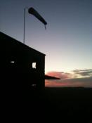
Howdy folks, time for an update on the big Stirling! I’ve been pottering away on this in the background and have finished off the gear bays (minus the oil tanks) and have given them, the wing bomb cells as well as the undercarriage a squirt of RAF night: I have also been playing with the props as I’m putting off finishing the cockpit interior as I hate doing them! With the sun out I’ve taken the old girl outside for some ‘this is how far I’ve come’ pictures - with one on the kitchen table for a size reality check, too! I suppose I better stop procrastinating and dive into that cockpit sooner rather than later… Until next time, Tom -
1/32 Short Stirling
ThomasProbert replied to ThomasProbert's topic in LSM 1/35 and Larger Work In Progress
It’s been a while since I’ve posted an update here, but work has been slowly progressing in the big Stirling… The nose turret has been done, using the HK Lancaster parts. The turret innards are identical so this part was easy, but the glazing had to be sanded smooth (the Stirling turret was frameless) and polished back to clarity. I then built a new fairing from plastic card and viola - the nose turret was done! The kit supplied bomb aimer’s glazing is incorrectly shaped so I’ve made my own framing from Evergreen strip and will drop the glazing in at a later date: I’ve also made a new fairing for the HK Lancaster rear turret - again these are identical in the later Stirlings and Lancasters: The kit canopy is woefully inaccurate - too big and the wrong shape: So… I contacted Peter at Airscale and he’s 3D printed a super thin canopy frame that sits on top of a new vac clear part: Unfortunately I’d previously cut the fuselage to fit the kit glazing, so some remedial work was needed to make the fuselage fit the new canopy: This was then done with plastic card and Milliput, and I now have a Tamiya-like drop fit so I can add the canopy just before painting: And that now brings you up to date. More when there’s more… Tom -
Greetings all - and all the best for coming year. Airfix 1/24th Hellcat II NF (F6F-5N), KD127, 892 NAS, Drem, Scotland, mid-1945. Here's my first completion of 2024 which nearly made 2023 but the cold, wet weather was against me for the final varnish coat! The Airfix 1/24th Hellcat is well known and documented so I'll save the background information but suffice to say it's one of the most enjoyable builds I've ever done - it's an absolute beauty of a kit and I loved building it. Whist there are some nice marking options in the box, I decided to go off-piste a little and do something different, hence buying the excellent Aerocraft set to make this into a Royal Navy night-fighter variant: The level of detail is sublime out of the box, and it went together beautifully with virtually no fit issues whatsoever. What I will say though, is tolerances are very tight indeed and the parts benefit from having their mating surfaces sanded slightly to cater for the thickness of the paint. The gun bays, for example, have a lot of the wing structure to add and thus very careful test-fitting was required to get that satisfying 'click' as it all goes together. The engine is a small model in itself - it took a total of three weeks to get it together and painted. Airfix give you a very detailed construction guide and this enables the builder to add the mass of wiring associated with the ignition harness - I used some aftermarket braided wiring and the effort was well worth it. The surface detailing is some of the best I've ever seen and gives a wonderful 3D effect - when you catch the right light it looks so realistic: Considering this was built OOB with the only additions being the seatbelts (I felt the kit examples were a little over-scaled), the ignition wiring and conversion set, it's exceptional value and quite a presence on the modelling desk. Paints were all Xtracolor enamels and I kept weathering effects to virtually none - these were, in reality, high gloss Dark Sea Blue and pretty clean. The stressed skin effect does most of the work for you to be fair, and other than some light exhaust staining I kept this in line with period photos of late-war Royal Navy Hellcats. To anyone considering building this, a few observations of the build process which may come in useful: As mentioned above, tolerances are very tight - gentle sanding of gluing surfaces and test-fits are a must and it will be very easy for things to become misaligned, especially in the gun bays; If you can, build the engine and main airframe as separate parts and bring them together after painting. I installed the engine as a completed unit prior to the main airframe being painted and this resulted in some very complex masking around the exhausts! The main canopy was quite a bit wider/flared at the base than the runners it is supposed to sit on. I had to coat the inside of the canopy with some Future (to avoid 'fogging') and then attach it with CA glue; The wing tip light lenses are slightly too large for the apertures they sit in - in hindsight I should have test-fitted these earlier in the build and not after painting! Be really careful when following the instructions as to whether you are doing wings folded or extended - the build sequence is very different between the two! Anyway, that's enough waffle from me! All the best, Tom
-
RN FG-1 Phantom 1/32 scratch conversion
ThomasProbert replied to Wingco57's topic in LSM 1/35 and Larger Work In Progress
This is looking so cool - and I’m so pleased to see the decals being put to good use!- 76 replies
-
- 1
-

-
- revell
- 1/32 phantom
- (and 1 more)
-
1/32 Short Stirling
ThomasProbert replied to ThomasProbert's topic in LSM 1/35 and Larger Work In Progress
A few more details added to the Stirling of late. As I’m doing a MkIII, they were fitted with the later FN50 mid upper turret which is a bonus, as I can utilise the HK turret from the Lancaster. However, the fairing around the turret was not provided in this kit so I’ve had to improvise a little… The fairing itself gave a little aerodynamic assistance, but it’s main purpose was provide a runner for cams that provided an automatic cut off to the guns, stopping over excited gunners blasting parts off their own aircraft. I initially wondered if I could use the HK models fairing from their Lancaster kit, but quickly discovered that their shapes were quite different. One day, I’ll get my backside in gear and learn how do design and print such items in 3D, but for the time being it’s back to the old-skool…Milliput to the rescue! Step one was place some masking tape over the area the fairing will sit. Once I’d consulted plans, I transferred the basic outline of the fairing onto the tape. Next, I made some Milliput ‘sausages’ and placed then in position, before using my long-forgotten sculpting skills from my school art lessons and set about creating the approximate form of the fairing. Milliput acts just like clay when wet, so it wasn’t actually hard to get the basic shape - just lots of consulting of pictures and plans needed: With the Milliput given 24hrs to harden fully, I peeled it off from the tape and fuselage, and with some fine sandpaper did the final shaping: This was then glued back to the fuselage, and viola! It won’t be perfect, but it’ll do. Next up was the gear doors. These were cut away as a whole when I made the wings. Astonishingly, I hadn’t lost them: The gear doors are a very complex shape - there are various gaps for the other doors to slot into as they retract as well as an opening for the lower part of that massive wheel to protrude. Again, looking at plans and pictures of the real aircraft, these were cut and shaped accordingly and some ribs added to the inner surfaces: Finally, they were attached to the gear: Here she is sitting pretty on the bench… my kitchen table! I now need to finish detailing the forward part of the main landing gear bays before I can squirt some paint on the bays and the gear to see how it all looks. Until next time, Tom -
rose of york Hong Kong Model 1:32 B-17 G “Rose of York” Limited Edition
ThomasProbert replied to Fran's topic in Aircraft Reviews
Waist guns are still staggered - therefore not strictly correct of BoL. You'd also need the earlier 3-pane windows. Tom -
RN FG-1 Phantom 1/32 scratch conversion
ThomasProbert replied to Wingco57's topic in LSM 1/35 and Larger Work In Progress
This is shaping up really well - it’ll really ‘pop’ when the decals start going on. Tom -
1/32 Short Stirling
ThomasProbert replied to ThomasProbert's topic in LSM 1/35 and Larger Work In Progress
Having returned from Telford (which was absolutely fantastic!) I've been all enthused/inspired and have made some more progress on the Stirling... The elevators were my next job - the molded hinge lines are often quite poor vacs such as these so I removed them when I made the stabilisers and planned to try to improve them a little. This also gives the advantage of being able to model them drooped like they usually were when the Stirling was at rest. Thankfully, I saved myself a bit of bother when I cut them away from the sabilisers and remembered to label which part of non-descript plastic was which... These were then sanded to reduce the thickness of the trailing edges and ensure the fit to the sabilisers was as good as it could be - I made a basic spar for each to get the thickness at the leading edges correct with the reduced taper as they progress outwards towards the tips. These were then attached to the stabilisers. The surface detailing is somewhat lacking, but looking at pictures of the real thing there is a very subtle fabric effect on the control surfaces, so I decided to do a little experiment. The ribs produce a very slightly raised line, with the unsupported fabric spaces between then sagging slightly. Therefore, I carefully cut the areas in between where the ribs would be with masking tape, and stuck these to the upper and lower surfaces: Three coats of primer were then applied: ...before removing the taped areas to leave very subtle raised ribs: These will need a very gentle sanding once the primer has cured for a couple of days, but I'm confident that under paint it will have a really good effect. Far better than anything I could have scribed, anyway! With this success I think I'll do the same for the ailerons and rudder... Next up will making the fairing around the mid-upper: Until next time, Tom -
1/32 Short Stirling
ThomasProbert replied to ThomasProbert's topic in LSM 1/35 and Larger Work In Progress
Morning guys and gals! I’ve been working on the huge flaps on this beast of late - they are absolutely massive and I imagine vital in providing extra lift to get this behemoth off the ground. These two pics (used purely for illustrative purposes) show them fully deployed as they often were seen when parked up: I set about them by carefully cutting plastic card to the correct shape for the upper and lower skins, bending the upper surfaces carefully in some very hot water (ouch!) to best replicate the aerofoil shape. I then cut out the runners for the flap tracks and scribed some surface detail - incorrectly at first as the plans I was using were wrong! The uppers and lowers were then carefully glued together over a wooden dowel to act as a spar and help keep the aerofoil correct: As with all scratch building, test fit, test fit, test fit… I then made all the rough edges good with Milliput white and added the distinctive bullet fairings beneath - these were actually old and spare H2S scanners from 1/48th Sanger Halifaxes and with some minor mods did the job perfectly! These will then fit the wing like so: And the undersides: I’m well ‘appy with those! Onwards and upwards! Until next time, Tom -
Pictures of the test shot build look very promising. The wing has been corrected (or at least is a big improvement on the 1/32 offering) and they’ve captured the aero foil shape much better to my eye. Unfortunately, it does seem like there are joints down the centre of the turrets again though 😞
-
1/32 Short Stirling
ThomasProbert replied to ThomasProbert's topic in LSM 1/35 and Larger Work In Progress
Howdy, partners… I’ve now completed the main bomb bay structure as well as the wing bomb cells on the Stirling. 250+ pieces of individually cut Evergreen has got the job done - quite tedious but the results are worth it. There will still be some more to add when the bomb load goes in such as racks and some piping, plus the doors of course. On the real aircraft the divider between the gear bays and the outermost bomb cell is actually open with the truss work exposed, but I’ve gone for strength over accuracy as beefy card is needed for the wheel bays and general wing structure to give it enough strength to support the model. I need to finish off the main gear bays but I’ve had enough if cutting plastic strip for the time being so will focus on something else! All the best, Tom -
Evening folks, With the summer holidays here, there's been some welcome additional modelling time and this was finished off over the weekend. I was given this by my dad who had in turn been given it by an old family friend - I think it is an original issue, and if not it's a very early issue of this classic kit from Airfix: I just wanted to build this more or less as it comes and enjoy it. However, I couldn't let the gaping hollow wheel bays pass so made some simple mods by adding plastic card sidewalls and some Evergreen stiffeners to at least make them sort of passable: Other than that, I used some Eduard belts for the pilot's seat, Barracuda wheels as the kit's had dried out and cracked when I tried to apply them to the hubs, and some aftermarket decals from Techmod to represent Von Werra's machine who crash-landed not far from me in Marden, Kent - and became 'the one that got away'. Although old and basic by modern standards, this kit is a joy and went together pretty well. Surface detail is sublime and the super-detailer could really have a field day if they were so inclined. I really enjoyed it as nostalgic build from days gone by and that's what it's all about! Evolution: here is the 109E alongside the G-model: like the Spitfire the basic airframe had huge potential to evolve and did so as the war progressed: Paints were all Xtracolor enamels with some weathering using Mig-Ammo pastels. A really enjoyable build - don't overlook these oldies as they scrub up really well! All the best, Tom
-
1/32 Short Stirling
ThomasProbert replied to ThomasProbert's topic in LSM 1/35 and Larger Work In Progress
Hi all, The engines have been my recent focus, and considering the Stirling shared the same ‘power-egg’ as the Beaufighter, I utilised the cowls and engines (from the Revell Beau) which has made work much easier - considering all you get in the kit are these bumps in plastic: First up, I assembled the cowls themselves, tarting them up a bit with some Evergreen and plastic card: The engines from Revell are actually quite good out of the box, and considering everything is black and very little will be visible, I built them OOB, painted them satin black and weathered them lightly with some oils. Atop the engine nacelles are big carb and supercharger intakes. The MkIII Stirling had a longer intake than the earlier MkI, and handily the Revell Beau gives a good starting point to use. These were sliced and then extended with Evergreen: And then blended with filler: Next, the finished power-eggs were mounted to the plastic card firewalls I’d made previously when constructing the wings, the intakes added to the 12 o’clock position on the cowlings, and viola: A lot of this work has taken place al fresco as it’s been so warm of late: So, here we are as of now: I need to have a think about the oil coolers which hang low under the nacelles, but that’s a job for another day. All the best, Tom -
1/32 Short Stirling
ThomasProbert replied to ThomasProbert's topic in LSM 1/35 and Larger Work In Progress
Time for and over-due update on the landing gear legs. The sprue structure has proved plenty strong enough so over the last few weeks I've been slowly making, adding and building up the details on these and have now more or less got the basic structures done and test-fitted. Lots of plastic card and Evergreen has been added to the basic sprue structure, and gradually it's all come to life: And after a glorious weekend away walking in The Lakes... ...I thought I'd have a proper test-fit of the gear as well as take some piccies using the decent camera set up. The undercarriage isn't attached yet as there's lots of detail still to be made and added to the bays - not to mention the painting of both the bays and legs - but a set of metal pins inserted into the spars as mounting points and holes of the correct size drilled into the upper-most past of the gear legs means they are a snug push-fit and support the model without glue. I've also made the basic twin-rear wheel set up by utilising Beaufighter tail wheels and legs, which with some mods have done the job. Not perfect replicas, but once the bays and doors are finished off not much will be seen anyway. It all looks very gangly at the moment, but when the undercarriage doors are added as well as the bomb bay doors, it should look the part. What to tackle next? The bomb bays or engines? Decisions, decisions. Onwards and upwards, as the old saying goes... Until next time, Tom -
You are quite correct - it is fitted with the standard D-model tail with the wider-chord rudder. I think it's just poorly written - the original rear fuselage as damaged and then replaced with another from a fellow D-model at the radio room fuselage break, hence the 'half and half' nickname being given. Tom
-
1/32 Short Stirling
ThomasProbert replied to ThomasProbert's topic in LSM 1/35 and Larger Work In Progress
I do it over the sink in water so dust is minimal. The wife does tend to get a bit excited if I don’t! Well… progress has slowed a little of late due to work, but I’ve made a tentative start on the very complex landing gear. This is a bit of an experiment, if I’m being totally honest, as I’ve knocked up some gear using spare sprue. I’ve no clue about working with metal or solder, so this may (literally) fall flat on its face, but we’ll see. I always keep large sprue trees as it’s so useful when it comes to scratch work. I’ve chosen some that’s a little thicker (by 0.25mm) than the HK Lancaster gear legs as my logic is if such diameter can support the heavier weight of that kit, it should be able to hold the much lighter vacform Stirling. So… some sprue and lots of small metal pins which will be used to reinforce each join: Following plans, I cut the main parts of the structure and these were then slowly put together. CA glue secured the metal pins in pre-drilled holes, and then when each ‘leg’ was complete TET was run into each join and allowed to dry for 24hrs to make a very strong join: Great care was taken to ensure each part of the gear was identical: The joins were then reinforced further with Milliput and sanded smooth: Next, the main cross members were added using more sprue and again strengthened with metal pins: And with the wheels added, they are starting to resemble the complex structure of the real thing: What I’m now going to do is temporarily fix the gear to the bays and leave it standing for a week. I’m off to Italy skiing so when I return, if the model is still standing securely on its gear I can call this a victory and crack on making and adding the rest of the detail - of which there is lots! If not, and I come back and it’s laying flat on its belly, it’ll be back to the drawing board and I may have to invest in a soldering kit and a whole lot of reading… Stay tuned! Tom -
1/32 Short Stirling
ThomasProbert replied to ThomasProbert's topic in LSM 1/35 and Larger Work In Progress
Very kind, Kev - thank you! The landing gear is certainly going to be the most challenging part of this build, so I thought I’d start with something relatively straightforward as a first, tentative step. When I inherited Cees’ parts he kindly threw in some spare HK Lancaster wheels which has been most helpful. The Stirling and Lancaster shared the same hub, but the Stirling’s tyre was larger. Plans consulted, I came up with a cunning plan… First up, I used some Evergreen block strip of the correct size to enlarge the Lancaster tyre to the correct diameter. Using strip, rather than a sheet of plastic card, means they follow the contours of the tyre well and reduce the amount of sanding needed later. Here you can see the modified wheels with the strip added: Next, I used some tape to protect the hubs, and layered on some P38. The rear-most tyre has already begun the sanding to shape: Both tyres sanded: And then primed: Not bad - although the shoulders need rounding off a little more. A job for another day. Until next time, Tom -
Ha ha! Due to table space limitations I'm not sure I'll be bringing the Sunderland - I may bring a few of my smaller builds instead!
-
1/32 Short Stirling
ThomasProbert replied to ThomasProbert's topic in LSM 1/35 and Larger Work In Progress
Greetings all More progress to update you on with the Super-size-Stirling! Since the last update the wings have been glued into place and the joins with the fuselage made good. Due to some careful planning in regard to the the spars and mating surfaces, very little filler was actually required which was a bonus. Next up I thought it made sense to tackle the fin and stabilisers as then the model will be structurally complete and the major sanding and preparing of parts will be completed. The kit parts are pretty basic but the shapes are good: Each part was scribed after careful consultation of plans. I concentrated initially on the fin - it was sanded to the correct depth and then I epoxied a wooden dowel more or less along the rudder hinge-line to act as a spar and strong attachment point to the fuselage: After more checking of plans a hole was then drilled into the top of the fuselage for the dowel to pass through and into the top of the spar-box I'd made for the stabilisers, meaning a very solid join. This is not the case with the real aircraft I hasten to add (there are very beefy rear fuselage frames that support the fin) but none of this is visible on the model so I went for strength over accuracy: With the fin set and filled, I then turned my attention to the stabilisers. Stirlings are more often than not seen with the elevators in a drooped position when at rest, so I thought it best to do the same with mine. First I removed the elevators from the stabilisers: And then glued some thick plastic card along the hinge-line to blank off the rear of the stab and also act as a spar: More dowel was then run through the rear fuselage: And then the stabilisers we epoxied in place, with the dowel butting up against the rear spar of the stabs making a very strong join. I made a rudimentary jig on the kitchen table with pots of paint and bits and bobs (nothing too technical in this house of mine!) to ensure everything was good and true: The small protrusions on the rear of the fuselage was different shapes on either side, and one slightly higher on the fuselage than the other, so lots of P38 was used to correct the shapes and help align everything properly: When all the filling, sanding and rescribing was done - and a splash of primer applied - everything came out ok: Deciding to have the flaps dropped meant the gaping hole along the rear of the wing needed addressing. This is curved metal skin, upon which flap tracks run on the real thing. There are also some fuel cells visible, but my skills don't stretch that far and neither to have the inclination when so little will be seen when the flaps are in place. The solution to making this was remarkably simple - I just cut some thin plastic card to the approximate shape and glued it to the lower wing skin, allowed this to set and then gently bent it to shape and aligning it with the upper surfaces. This was then clamped whilst everything dried: And when dry it was trimmed to the correct shape, primed and... success! When it comes to making and adding the flaps themselves, the flap tracks etc. will be added then. I have also removed the opening for the front turret: I am not completely convinced the shape is exactly correct yet - the nose may be a smidge too wide - but I'm going to leave this for a bit and see if any further remedial work will be needed whilst i get used to the new nose profile. So that brings you up to speed - something resembling a Stirling is slowly emerging from some bumps in plastic so I must be doing something right! As always, thanks for stopping by. Until next time, Tom -
I'll certainly be there - pop by the IPMS West Kent stand and say hello! Tom
-
They are hosting a model show there on May 14th this year - if you pay a visit then you'll get the bonus of Mosquitos and lots of models to look at! Tom
-
1/32 Short Stirling
ThomasProbert replied to ThomasProbert's topic in LSM 1/35 and Larger Work In Progress
Afternoon all, Lots of progress on the big Stirling to update you on. Being a teacher on half term has its benefits and there's been a lot more bench-time than usual this week. The interior areas that are visible have had some more details made and added and a squirt of paint applied. Here’s the forward fuselage and cockpit area: And the rear: It goes without saying that there is a huge amount to be added to the cockpit, but this is easily accessible and will added just before the canopy goes on to avoid any damage from the filling/sanding/scribing that’s to come. With the interior painted, I could join the fuselage halves together - the fit was pretty good and the interior bracing and bulkheads I'd made meant everything aligned as it should. With the joints glued and set I removed the opening for the mid-upper turret, and used plastic card to blank off the kit wing-roots which are incorrectly positioned: All the joints then got a coat of P38 car body filler, and were then sanded smooth. With this done, scribing could begin. I'm often asked about the tricks of scribing kits such as this, and the truth is it's very simple. Using plans as a guide and some dymo-tape, panel lines are instated with a Bare Metal Foil Co. scriber and then sanded smooth with some fine sand paper. This allows the curves of the fuselage to be done as well as the straight, flat panel joints. The whole fuselage on this only took an evening: These pictures show the finished fuselage - although being white my handiwork with the scribing doesn't show up at all well. Note also I've now added the wing spars: So now it's time to start thinking about adding the wings - they will slide nicely over the spars which interlock with the interior structure I made previously: The wings are just resting in the following two shots and the correct dihedral not set, but it gives an idea about the overall shape: As you can see, she's a big old brute. And once again, the wife isn't impressed - but nothing new there... The next task will be adding the wings and making the joints good - with the classroom beckoning again tomorrow things will slow a little again but I'll update this when there's some more progress to report. Cheers, Tom -
1/48th HP Halifax BIII - Fonderie Miniatures
ThomasProbert replied to ThomasProbert's topic in Non LSM 'WIP
Thanks for the kind words, chaps. It was indeed a bit of a struggle and therefore it one of those builds that I dabbled in when I felt brave enough. It certainly is not a kit for the inexperienced builder but a decent result can be obtained if you give it time - as Cees is so ably demonstrating. And yes - a modern tooling in 1/48th would be a good seller for sure! A very underrated aircraft in need of some love and recognition! -
This build has been on and off (more off than on to be fair) the bench for the last 7 years! It finally crossed the finish line earlier this week and thank Christ for that! Fonderie kits have a poor reputation but when I first bought this and fellow modellers imparted their horror stores I didn't think it could be that bad. I was wrong. It was worse. It didn't look too bad in the box to be fair - lots of flash but nothing a good clean up with a new blade and a sanding stick couldn't put right. It was when I started building the thing that the true horrors emerged. The fuselage was badly warped, the interior parts simply didn't fit, wings were different thicknesses, one stabiliser was positioned higher on the fuselage than the other, the vacformed canopy and tail turret were hopelessly inaccurate and not worth using, the rear fuselage had the turret faring missing and it was too narrow, props were completely the wrong shape, most white metal parts, including the undercarriage legs, were badly warped and mis-shaped, dropped flaps fouled the bomb bay doors and the decals, probably due to age, had yellowed and broke up when I tested them in water. In short, it was a nightmare and was a resident on the Shelf of Doom for long periods as I plucked up the courage to do some more work to it. 7 years later and it was finally done. Work completed is summarised here: - Interior mostly made from scratch - Scratch-built bomb-bay and wing bomb cells - Bomb load from the Tamiya Lancaster - New vacformed canopy (thanks Neil!) - Rear fuselage widened and new turret fairings made - Sanger vac rear turret transparency used - Prop blades slimmed down and rounded (I'm still not happy with the shape!) - 100 Group aerials added - Xtracolor enamels - DK decals Anyway, it was fun I suppose and she's not come out too badly. My model represents Handley Page Halifax B Mk III MZ913, Z5-N of 462 Squadron RAAF, Foulsham (100 Group), April 1945. All the best, Tom
-
1/32 Short Stirling
ThomasProbert replied to ThomasProbert's topic in LSM 1/35 and Larger Work In Progress
I can guarantee that as soon as I put the finishing touches to this, one of the mainstream manufacturers will step up!
