

sandbagger
-
Posts
1,328 -
Joined
-
Last visited
Content Type
Profiles
Forums
Events
Gallery
Everything posted by sandbagger
-

1:32nd scale - Bristol M1.c
sandbagger replied to sandbagger's topic in LSM 1/35 and Larger Work In Progress
Hi all, All decals applied now and weathering done. Weathering is a mix of 'Flory' Grime clay wash, 'Tamiya' Weathering Master Set A, C and D (Gunmetal, Mud, Sand) and 'AK Interactive' enamel wash (Kerosene 2039 and Engine oil 2019). All seal in with 'Alclad' Light Sheen lacquer (ALC311). Now onto construction and rigging, Mike -
1:32nd scale - Bristol M1.c
sandbagger replied to sandbagger's topic in LSM 1/35 and Larger Work In Progress
Hi all, I decided to employ the same technique I used for the Ansaldo 'Baby' and create the linen effect using the 'Aviattic' weave effect decal (ATT32236). This was not an easy task for the fuselage, as it has a round section which also tapers towards the rear of the fuselage. This meant that I couldn't apply the decal as large pieces, as they would have folded and creased as they were applied towards the tapered rear of the fuselage. Instead I had to cut multiple paper templates to span only two fuselage longerons at a time. Then trace these templates onto the decal sheet, cut out the decals and apply them one by one, which took 9 hours. However I think the effect may have justified the effort. Now it's onto the wings, ailerons, fin, tailplanes and elevators, which should be easier, Mike -
1:32nd scale - Bristol M1.c
sandbagger replied to sandbagger's topic in LSM 1/35 and Larger Work In Progress
Hi all, I've replaced the kit supplied Vickers Mk.1 machine gun with one from 'GasPatch'. The actual aircraft had a ring site fitted to the weapon, which wasn't on the kit part, so I used a spare from a 'Wingnut Wings' Sopwith Camel kit, Mike -
1:32nd scale - Bristol M1.c
sandbagger replied to sandbagger's topic in LSM 1/35 and Larger Work In Progress
Hi all, The underside of the wings and fuselage were said to be a light blue colour, in order to reduce the absorbed heat reflected from the ground. It is thought the propeller spinner was of the same colour. The colour of the upper surfaces has been depicted as either a red/brown (PC 12) or an olive green (early PC10). The kit instructions and most colour profiles have the PC12 colour. However, the ‘Windsock’ Data file No:52 colour profile is PC10. As always the definition of colours from early monochrome photographs has always been problematic and the shade differences between PC10 and PC12 are no exception. The ’Windsock’ Data file states that it is possible that these aircraft were painted with PC12 when routed through the aircraft depot at Salonika, Greece. However, it was more likely the colour of aircraft operated in Macedonia was PC10, with the possible exception of No.72 Squadron. I decided to use the PC10 colour, based on the ‘Windsock’ data. The paint used was 'Hataka' lacquer Dark Olive Green (C301). Mike -
1:32nd scale - Bristol M1.c
sandbagger replied to sandbagger's topic in LSM 1/35 and Larger Work In Progress
Hi All, I've been working on the undersides of the Bristol, which had the lined doped in light blue to help reflect the heat whilst operating in Mesopotamia. First was to prime grey then mask off the wing ribs and fuselage longerons. Then pre-shade using 'Tamiya' Smoke (XF19). Lightly overspray with 'Tamiya' Light Blue (XF23). Then remove all masking and a final light top coat of the light blue. The propeller assembly was done at the same time. Now it's onto painting to top surfaces with PC10, which the 'Windsock' data file suggest would be correct (not the brown PC12 often used). Mike -
1:32nd scale - Bristol M1.c
sandbagger replied to sandbagger's topic in LSM 1/35 and Larger Work In Progress
Hi all, I've added the bungee type suspension cord to the axle ends, using 'EZ' heavy line (white). Also the half hoops at the axle ends, inboard from the base of the undercarriage struts. Made from annealed 0.4 mm diameter rod. Mike -
1:32nd scale - Bristol M1.c
sandbagger replied to sandbagger's topic in LSM 1/35 and Larger Work In Progress
Hi all, The wings are supported by a strut assembly over the cockpit. The kit supplied struts are intended to be 'butt' glued together at the top and into shallow recesses in the fuselage sides. Not a very satisfactory assembly and probably not really strong enough to take the weight of the solid wings with rigging. Therefore I've replaced them with aero-shaped tubing with 0.4 mm diameter rods for locating into the fuselage. The whole assembly is soft soldered for strength, Mike- 38 replies
-
- 10
-

-

-
Hi all, Here's the shots of the completed Italian Sopwith ‘Baby’ (Serial No. So.5005), built under license by the SA Aeronautica Gio Ansaldo of Turin. The resin model is from 'Lukgraph. The forum build log for this model can be found here: A fully detailed build log, in PDF format, will be available to view or download from gallery 2 on my site (just click on the PDF icon) in the site link below, Mike
-
1:32nd scale - Bristol M1.c
sandbagger replied to sandbagger's topic in LSM 1/35 and Larger Work In Progress
Hi all, Just a few updates. I've modified the front end to accept a 'ProperPlane' laminated propeller ('Lang' type). This entailed replacing the propeller shaft on the engine with 2.0 mm tube and filing the front face of the spinner support ring. Also sanding the rear face of the propeller hub, re-profiling the spinner cut-outs and thinning the walls of the engine cowl and spinner. The Vickers Mk.1 machine gun was replaced with a 'GasPatch' version, which required lengthening the fuselage recess to accept the weapon. The two ammunition feed guards were also slightly re-profiled. I also drilled out what was a solid ammunition ejector chute. The undercarriage struts attachment to the fuselage was poor and didn't allow for the struts to be angled correctly. These were modified to have 0.4 mm diameter locating rods and the tops of the struts chamfered to the shape of the fuselage. Also the two axle torque bars were replaced with stronger 1.0 mm diameter rod. Mike -
1:32nd scale - Bristol M1.c
sandbagger replied to sandbagger's topic in LSM 1/35 and Larger Work In Progress
Hi all, The cockpit is ready to be fitted into the fuselage, when most of it won't be visible (why do we do it). Additional pipes are 0.4 mm diameter lead wire. Engine control rods are 0.4 mm diameter Nickel-Silver tube, chemically blackened with 'Black-It'. The supplied seat harness was photo-etch and looked remarkably the same as the 'Eduard' set for the WW2 Fairy 'Swordfish' aircraft. Needless to say I replaced them with the coloured textile set from 'HGW Models', Mike.- 38 replies
-
- 10
-
-
-
1:32nd scale - Bristol M1.c
sandbagger replied to sandbagger's topic in LSM 1/35 and Larger Work In Progress
Hi all, Most of the cockpit has been assembled now. The control lines and bracing lines are 0.08 mm diameter mono-filament, with 0.4 mm diameter Nickel-Silver tubes and 'Gaspatch 1:48th scale turnbuckles. I've still fit the engine controls and rods and the pilot's seat with harness. Then it's a bit of weathering and finally sealing, to add the semi-sheen finish to the wood work and leather seat cushion, Mike -
1:32nd scale - Bristol M1.c
sandbagger replied to sandbagger's topic in LSM 1/35 and Larger Work In Progress
Hi all, I'm working my way through the cockpit assembly. Most is assembled ready for painting. There are other parts to add after they've been painted. I've drill 0.3 mm diameter holes and added 'GasPatch' 1:48th 'one end' turnbuckles to the rudder bar. Added a 0.3 mm rod to the control column to add strength to its attachment to the floor (hole drilled to receive the rod). I've also drilled 0.3 mm diameter holes across the control column for the elevator control wires. The instrument panel of the cockpit right side frame is orientated incorrectly in the instructions. The photograph shows how it was mounted, so I've gone with that, Mike -
1:32nd scale - Bristol M1.c
sandbagger replied to sandbagger's topic in LSM 1/35 and Larger Work In Progress
Hi all, The engine for the Bristol is done. It's the basic kit engine with just the ignition leads added. The leads were made from twisted 0.125 mm copper wire and annealed to soften and discolour them. The engine was painted with 'Alclad' lacquers - Black Base (ALC-305-60), Steel (ALC-112) and Exhaust Manifold (ALC-123). The kit engine was used as it is a good enough quality not to require an aftermarket version. Besides, once fitted, very little of the engine will be visible inside the engine cowl and behind the propeller and huge spinner. Now it's onto the cockpit, Mike -
Hi all, After the trials and tribulations of several resin model builds recently, I thought I'd do a 'mojo' build. I've chosen the 'Special Hobby' 1:32nd Bristol M1.c 'Bullet'. This particular model build will depict the Bristol M.1c ‘Bullet’, Serial No. C4907 of No.150 Squadron RAF, operating in Macedonia during 1918. This aircraft was flown by Lt. K.B. Moseley, who was credited with the shooting down of an Albatros D.V on the 9th of July, 1918 over the Rupel Pass. This same aircraft was also flown by Lt. J.P. Cavers, who was credited with the shooting down of a LVG on the 1st of September and another LVG on the 2nd of September. The underside of the wings and fuselage were said to be a light blue colour, apparently to reduce the absorbed heat reflected from the ground. It's thought the propeller spinner was of the same colour. The colour of the upper surfaces has been depicted as either a red/brown (PC 12) or an olive green (early PC10). The kit instructions and the colour profile by artist Ronnie Barr have the PC12 colour, whereas the ‘Windsock’ Data file colour is PC10. As always the definition of colours from early monochrome photographs has always been problematic and the shade differences between PC10 and PC12 are no exception. The ’Windsock’ Data file states that it may have been that these aircraft were painted with PC12 when routed through the aircraft depot at Salonika, Greece. However, it was more likely the colour of aircraft operated in Macedonia were PC10, with the possible exception of No.72 Squadron. I've decided to use the PC10 colour, based on the ‘Windsock’ data. Mike
-
1:32 scale Ansaldo 'Baby'
sandbagger replied to sandbagger's topic in LSM 1/35 and Larger Work In Progress
Hi all, I've now completed the bracing wires for the main floats. Now I'm finishing off the ailerons and their control cables. The cable pulleys for the upper wing are resin and I don't think are strong enough to take the tension on the rigging line. Therefore I disregarded them and instead made pulleys from 0.2 mm thick plastic card and 0.8 mm brass rod. Once the ailerons are sorted I only have a few items to do, such as the pitot tubes, pilots step, float keel etc. Also I'm waiting for the display case and propeller to be delivered, so I can complete this model. This will be the last update for this model. I'll post photographs of the complete build once it's done. Thanks for everyone's comments and support during this build - much appreciated, Mike -
1:32 scale Ansaldo 'Baby'
sandbagger replied to sandbagger's topic in LSM 1/35 and Larger Work In Progress
Hi all, The rigging for the wings has been done, apart from weathering and sealing. Rigging line is 0.12 mm diameter mono-filament with 0.5 mm diameter tubing. The crossed bracing wires from the top of the front cabane struts to the top of the fuselage are not shown correctly in the kit instructions. In reality, the two lines crossed through an 'acorn', similar to that for the Sopwith Camel. The acorn was made from plastic rod and drilled through with a 0.3 mm diameter hole. Next is to fit and rig the main floats and after that, fit and rig the ailerons, Mike -
1:32 scale Ansaldo 'Baby'
sandbagger replied to sandbagger's topic in LSM 1/35 and Larger Work In Progress
Hi all, I think I know what the problem is. Browsers, such as Google Chrome, are migrating to more secure browsing. Traditionally, images or web sites linked with a URL address with http:// are being superseded with https://. This entails someone like me having to purchased and install an SSL certificate for my hosting server, so my web sites and images will show using the various web browsers. I've started the process of SSL certification and once that's sorted I'll probably need to arrange re-direction of images previously linked to the http:// URL. Hopefully then me and others won't have the problem of my posted photo's not showing. We'll see, Mike -
1:32 scale Ansaldo 'Baby'
sandbagger replied to sandbagger's topic in LSM 1/35 and Larger Work In Progress
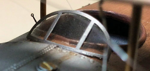
Hi all, The windscreen has been fitted using the kit supplied photo-etch frame and template cut out acetate transparency. The upper wing has also been fitted. I had the usual tricky problem of locating all of the struts and at the same time making sure the wings are correctly positioned and aligned. So now it's onto final rigging for the wings, Mike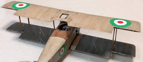
-
1:32 scale Ansaldo 'Baby'
sandbagger replied to sandbagger's topic in LSM 1/35 and Larger Work In Progress
Hi all, Just as a heads up. Last night I posted photos for this build in the same way I have for years, linked from my hosting provider to the forum. Later last night I went to the forum and found that every build photo, of any of my builds, had disappeared. Not only from this forum but also from others I post in. I could see everyone else's photo, just not mine. A couple of various forum members have experienced this problem over the past couple of weeks. When I checked on my android mobile and Apple IPad devices, I found my Ipad showed the photos, but my mobile did not. I then tried Microsoft Edge as the browser on my PC and the photos showed. Judging by comments made by forum members after I'd posted the photos', they obviously could see them, even though I could not. The only common factor stopping my photos from showing was Google Chrome, my default browser on my PC and mobile. I've checked all of the known problem settings, but still no joy. Therefore I've switched browsers to Edge and everything is OK now. Just thought I'd mention this in case others run into the same problem, Mike -
1:32 scale Ansaldo 'Baby'
sandbagger replied to sandbagger's topic in LSM 1/35 and Larger Work In Progress
Hi all, I've completed pre-rigging the fuselage and wings, apart from the main floats and ailerons. The rigging is 0.12 mm diameter mono-filament with 'Gaspatch' 1:48th scale turnbuckles and anchor points. The next step is the fitting of the upper wing before final rigging, Mike -
Das Kamel - Hansa Brandenburg W.12
sandbagger replied to DocRob's topic in LSM 1/35 and Larger Work In Progress
Hi Rob, Just caught up with this build. Great to see you building the W.12. I've built the W.29, but the W.12 is still on my 'to do' list'. I know your pain with some HGW decals and photo-etch. I only use their seat belts now, as I've also found their decals way too fragile and reluctant to stick and some photo-etch design/fit problems. Looking forward to your progress, Mike -
1:32 scale Ansaldo 'Baby'
sandbagger replied to sandbagger's topic in LSM 1/35 and Larger Work In Progress
Hi all, The tail unit is complete now. Rigging is 0.08 mm mono-filament for the control lines and float bracing wires - Fin bracing is 0.12 mm. Tubing is Nickel-Silver 0.4 mm diameter. I replaced the float rudder operating bar with tubing and had to create the rudder/fin bracing bar (not included in the kit). The tail plane support struts in the kit is just brass rod, so I made aerofoil struts from tube with internal support rod. Mike -
1:32 scale Ansaldo 'Baby'
sandbagger replied to sandbagger's topic in LSM 1/35 and Larger Work In Progress
Hi all, The bracing for the tail float is now done, apart from painting the tubing. I'm now working on the tail float rudder and aircraft rudder/brace bar (which is not included in the kit). There are several problems with the tail float rudder, which required modification using micro-tube, drilling of location hole and reprofiling the rear face of the tail float. Also the creation of the aircraft rudder/brace bar, which also required a hole drilling, Mike -
1:32 scale Ansaldo 'Baby'
sandbagger replied to sandbagger's topic in LSM 1/35 and Larger Work In Progress
Hi all, I'm now working on the tail unit, starting with the rear float. First is to pre-rig the eight bracing wires between the four support struts. The mono-filament used is 0.08 mm diameter with 0.4 Nickel-Silver tube and 1:48th scale turnbuckles from 'GasPatch'. Next step is to fit the float and struts then complete the rigging from the fuselage to the float, Mike -
1:32 scale Ansaldo 'Baby'
sandbagger replied to sandbagger's topic in LSM 1/35 and Larger Work In Progress
Hi all, The lower wing, the wing ailerons, tail plane assembly and rudder fitted. Now it's onto pre-rigging, the struts and then start assembly. Mike