CrankyCrafstman
-
Posts
1,350 -
Joined
-
Last visited
Content Type
Profiles
Forums
Events
Gallery
Everything posted by CrankyCrafstman
-
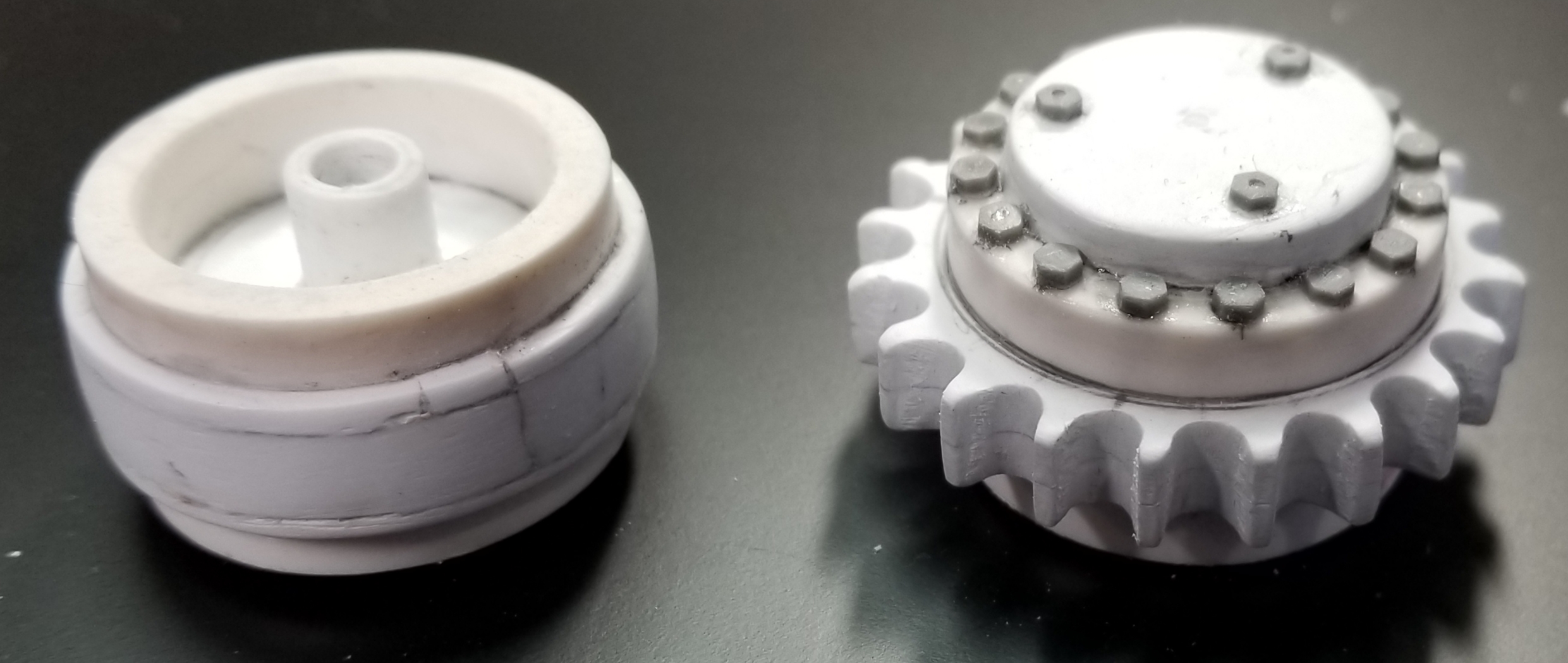
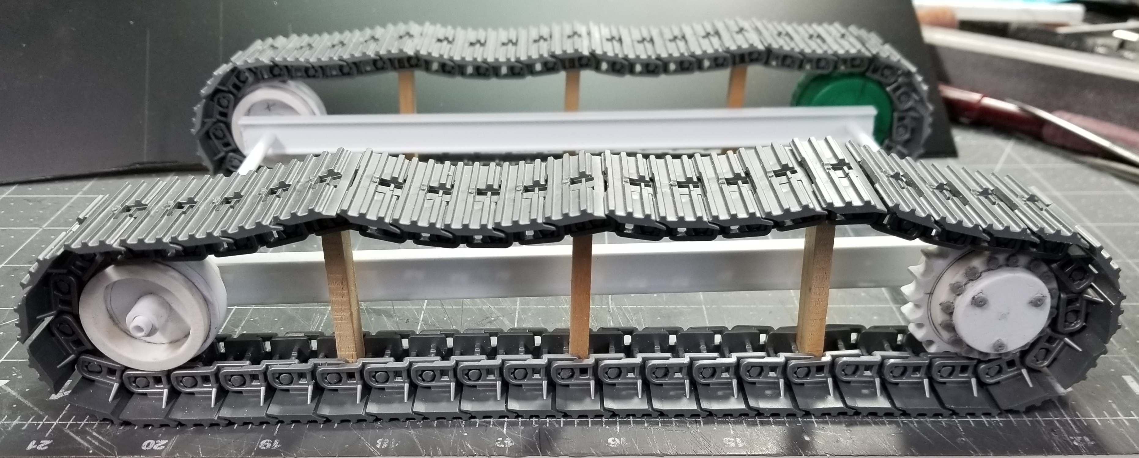
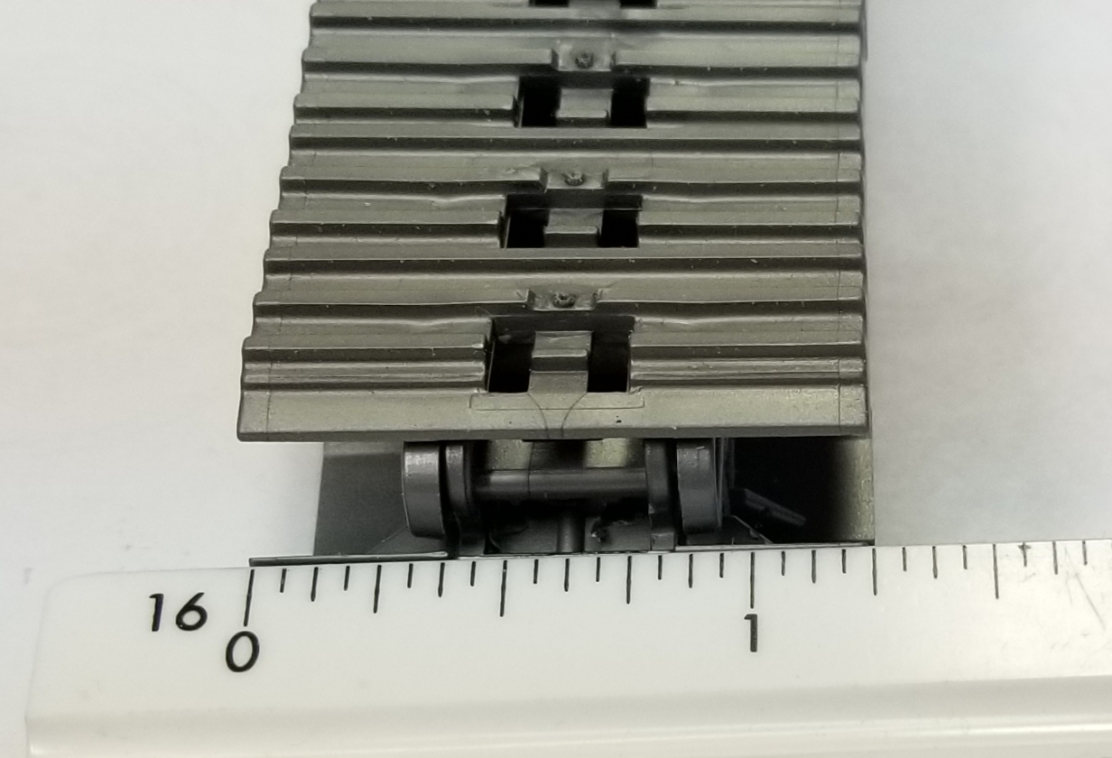
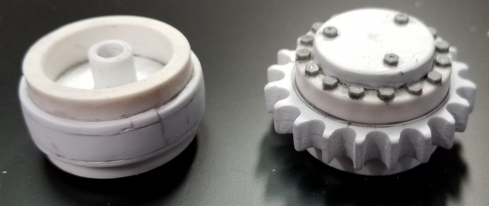
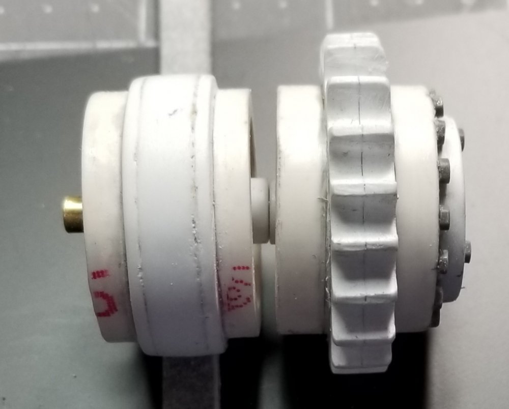
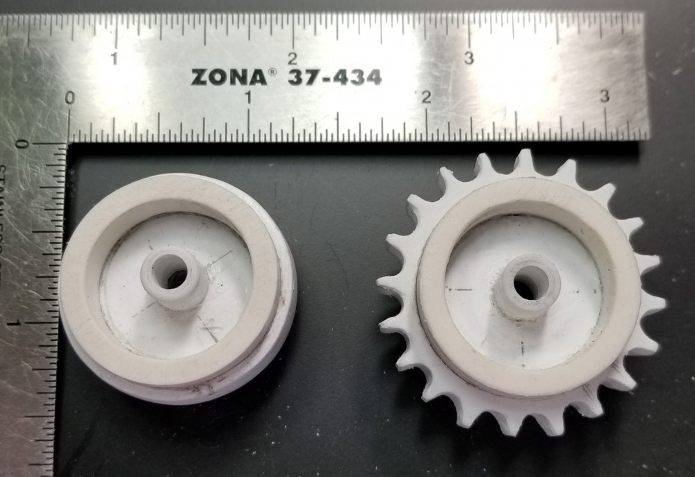
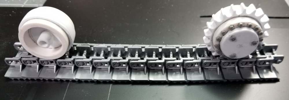
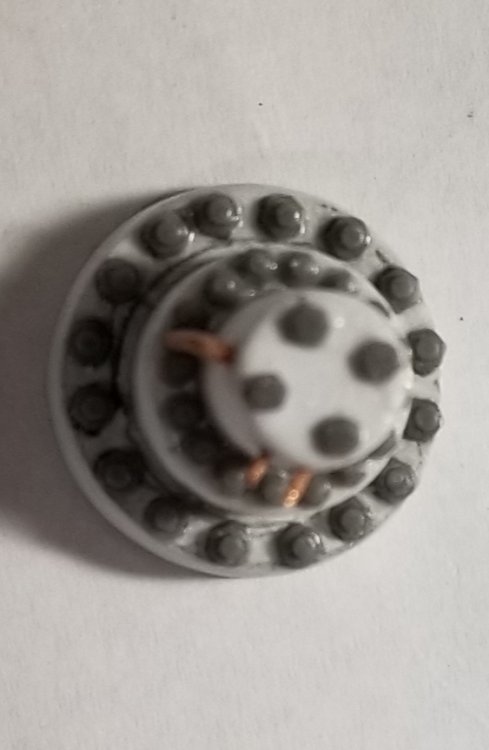
 Hey all Another small update for you all. I have one of the drive sprockets done. this view shows the drive sprocket and the idler together. I made the sprocket out of the same 3/4" PVC pipe that I used for the idler. The teeth are made from some 1/8" thick plastic sheet glued together to make it 1/4" wide. I drilled out the notches for the track link pins with a 1/8" diameter drill bit, all 20 of them. I then ground out the center of the sprocket teeth to the OD of the PVC pipe. I glued this to the center of the peice of pipe, I then sanded it to the correct diameter. I added a piece of 1/8" thick plastic sheet cut to the ID of the pipe and glued on to the outer edge of the sprocket and some 7/32" & 9/32" diameter plastic tube to create the hub. To this I added some 2.6mm Meng bolt heads, and presto chango you have a drive sprocket...lol more of a side view of the two. end view of the idler and the drive sprocket. this view shows them next to a scale. this view shows them sitting on some of the track peices. this view shows the idler and the drive sprocket in place in the tracks. Well that's it for now be back soon. Ron G
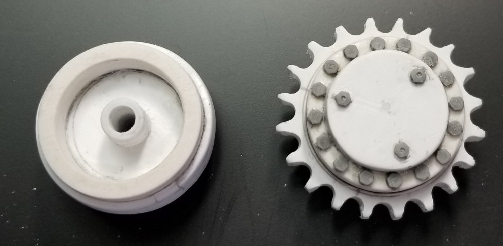

-
Thanks guys
-
Thanks Harv
-
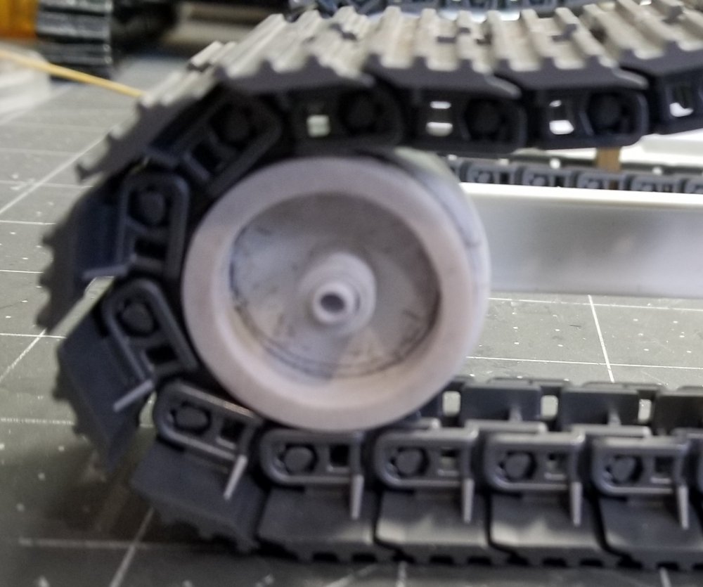
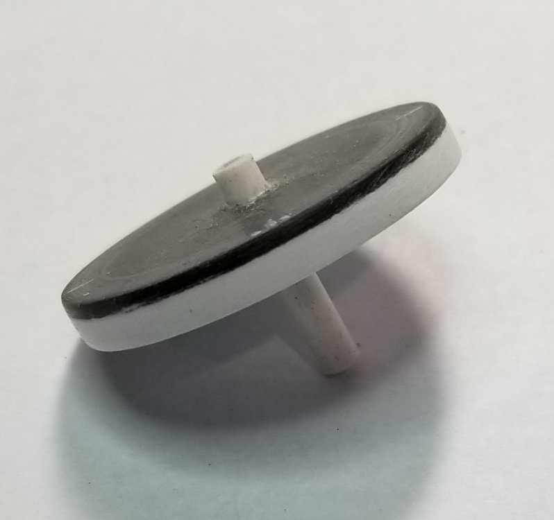
Hey all Small update for you all. I have the front idler wheels done. here it is, I made this from a piece of 3/4" P C pipe.that is 1.07" O.D. plus some plastic strips glued on the center of the wheel for the track guide. Then some 7/32" & 9/32" plastic tube for the hubs. this view shows both of the idlers. this view is were I'm at up to this point. It doesn't look like much but it was a real challenge to figure out and build. Ron. G
-
Hey Jeff It might be because they are going out of business, they were bought by Rustoleum Ron G
-
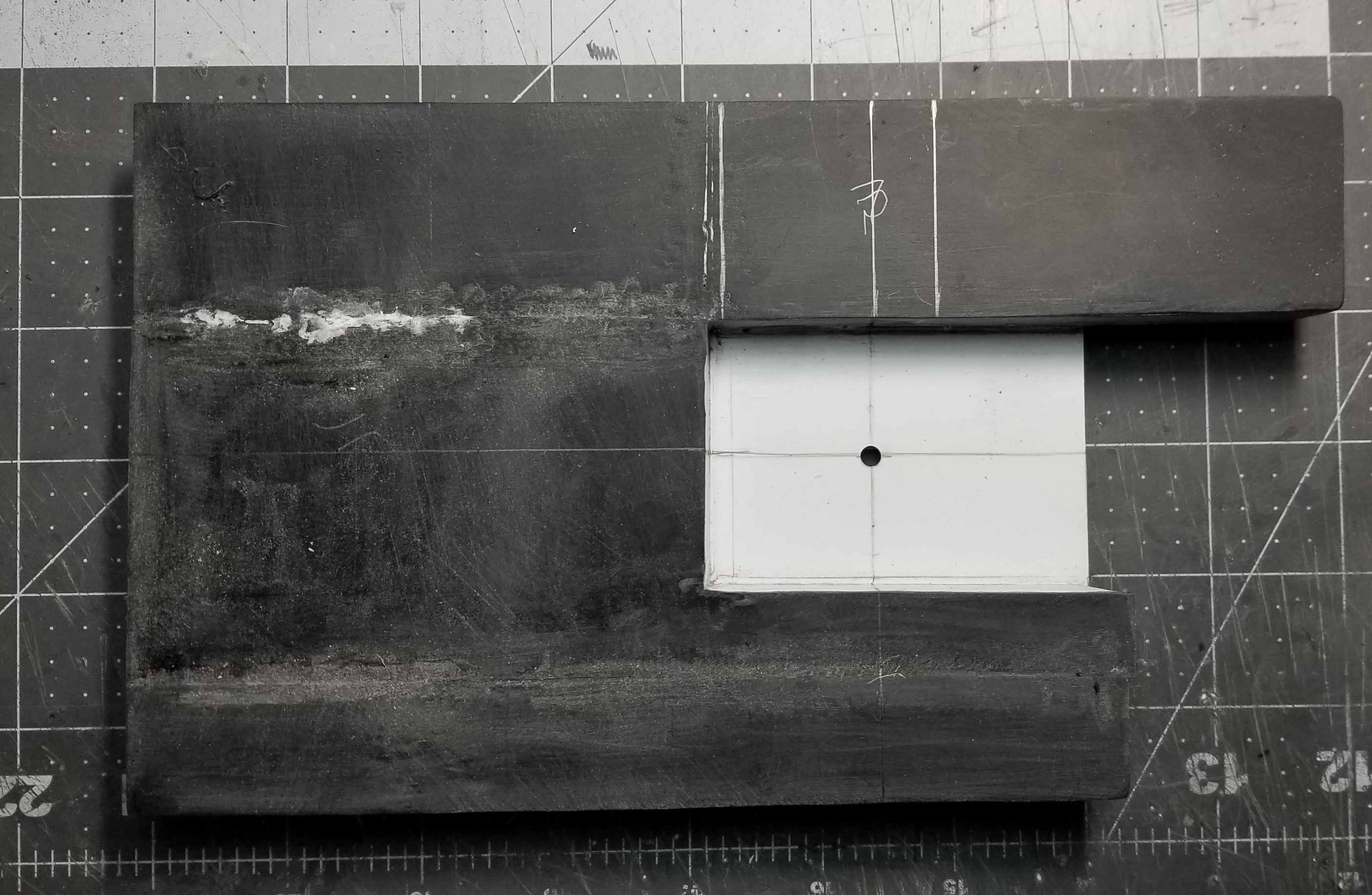
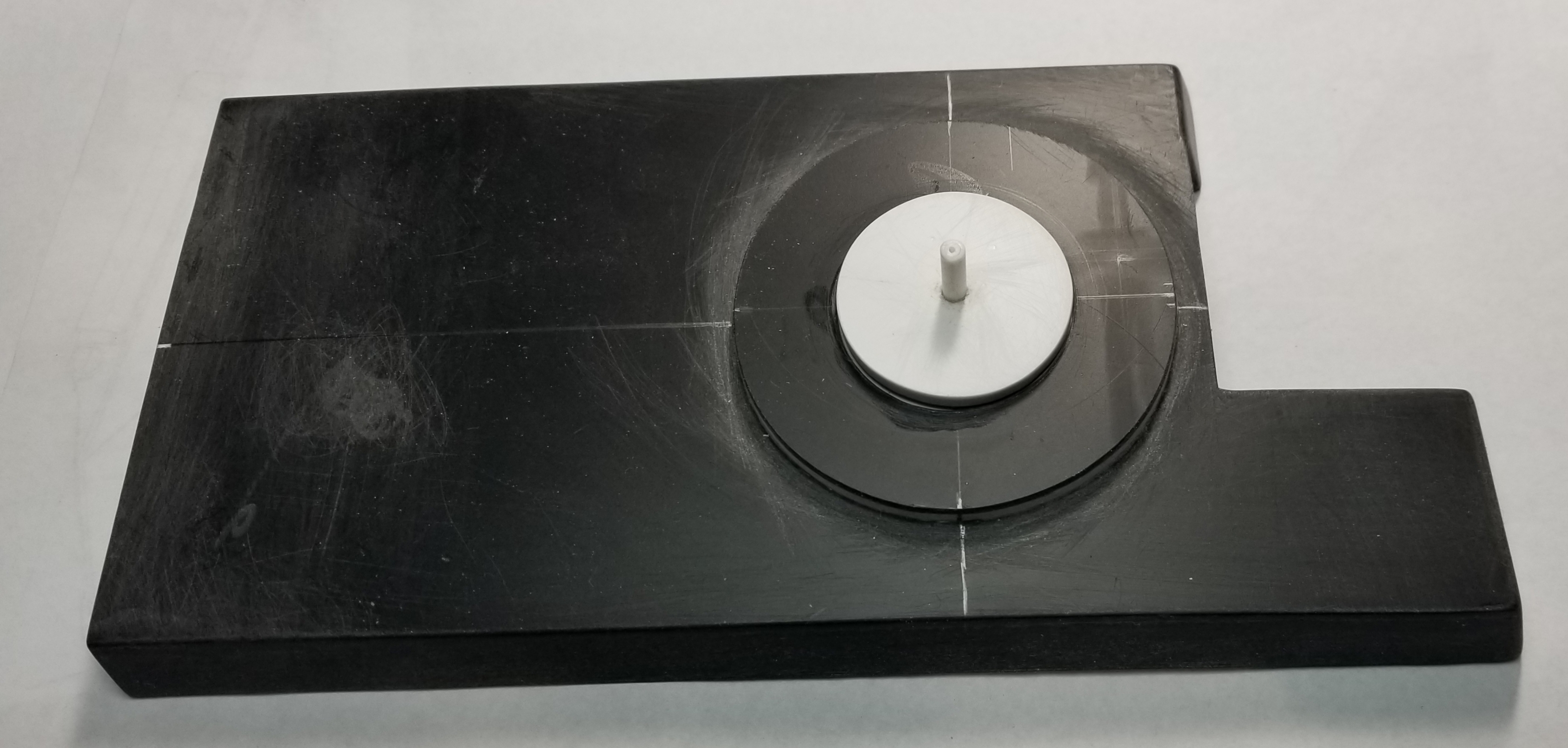
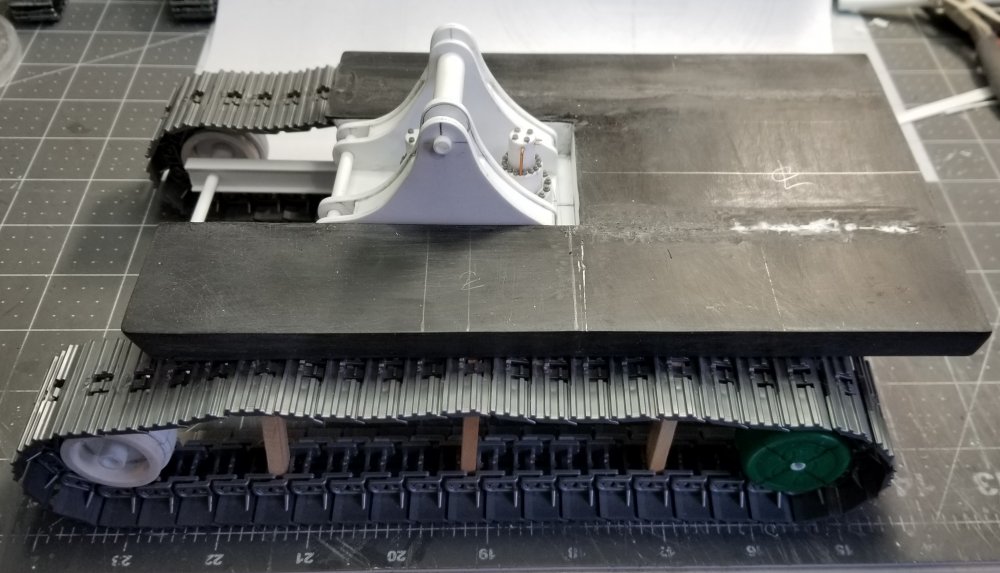
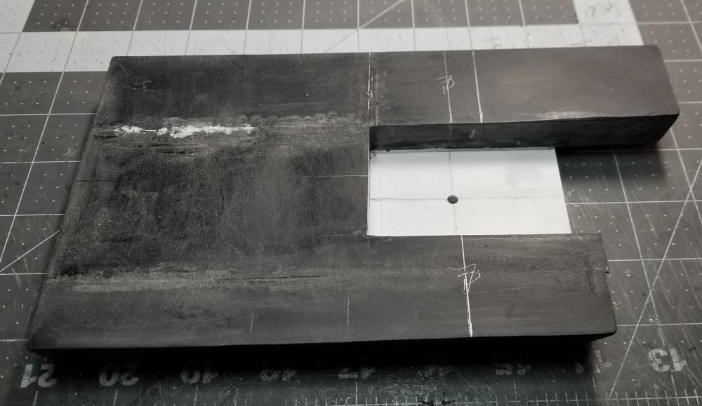
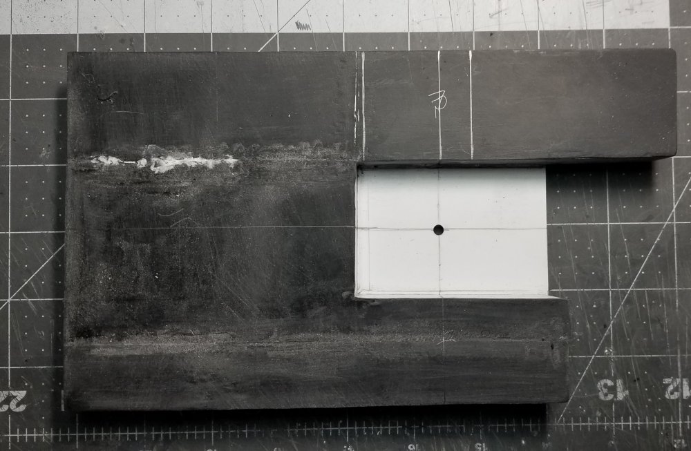
Hey all Well not so great Mark. You know the old saying 1 srep forward, 2 steps back. Well after rechecking my drawings and photos i found out I made an error.... When I started to draw the rear view in order to get the counter weight right I found out I made the base to narrow. I had it at 9' 0" which put the boom pivot bracket off center, plus it just lookedway to narrow, opps! So after some calculations I ended up making it 10' 6" wide, with 10' 0" track gauge instead of 9' 0" that I had. It looks way better now. Hey Jeff definitely going to need permits for this one...lol this view shows the newly reworked base. top view of the new base. this view is of the bottom of the base, you can see the piece that I had to add to the middle of the base this view shows the new base with the boom pivot bracket sitting in place on the base. Hopefully I won't mess up again, yeah right! who am I kidding. Ron G
-
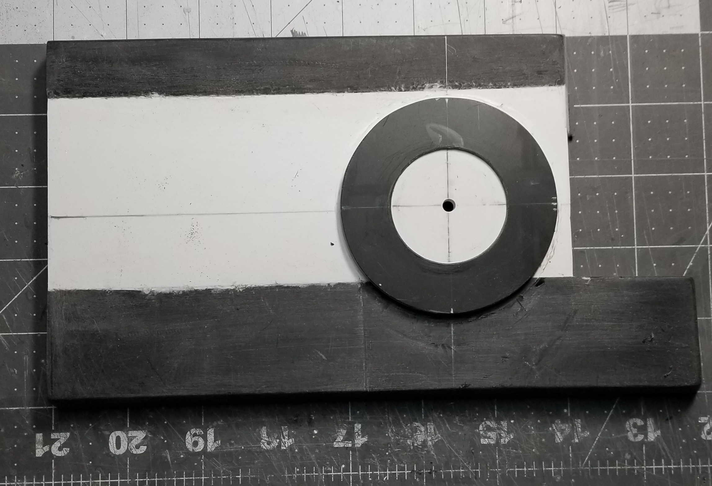
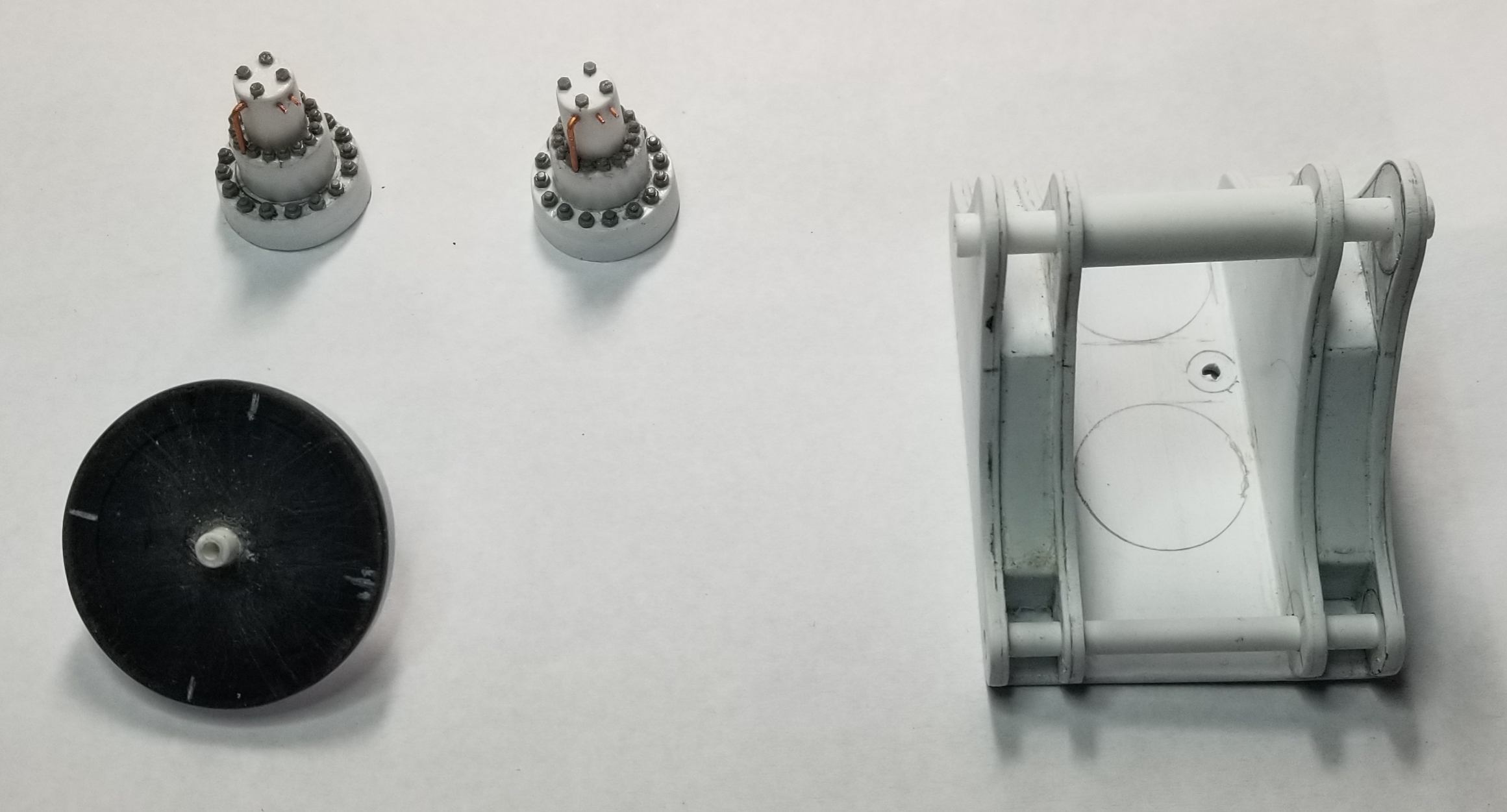
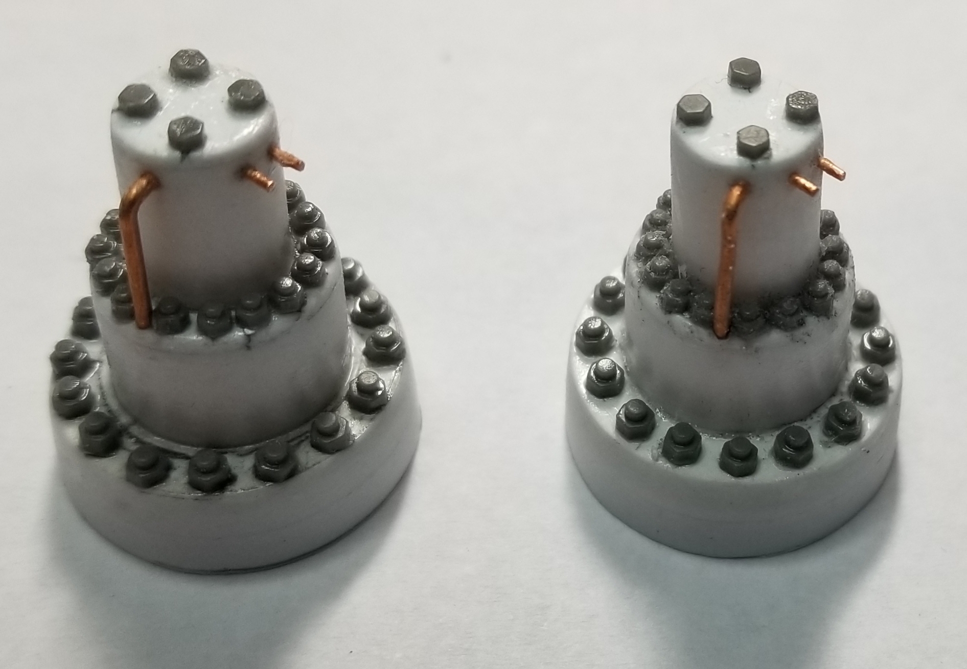
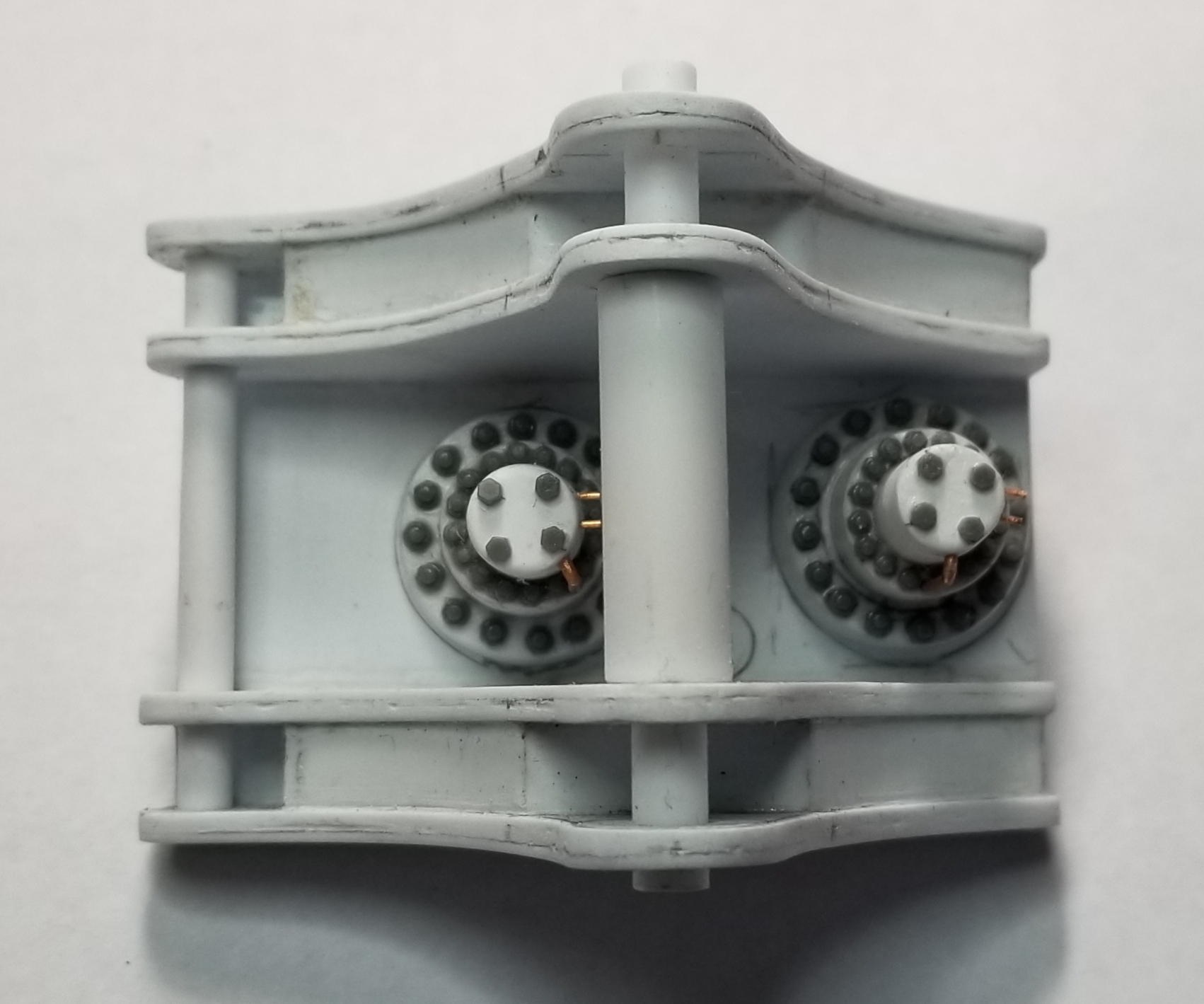
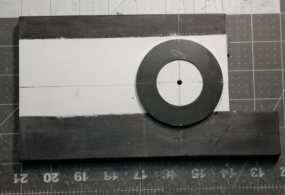
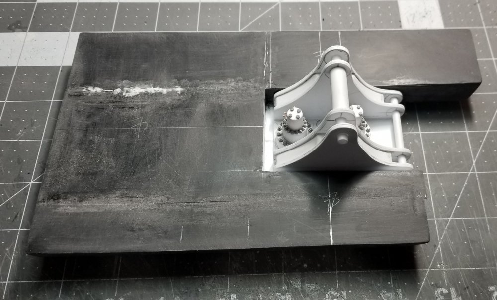
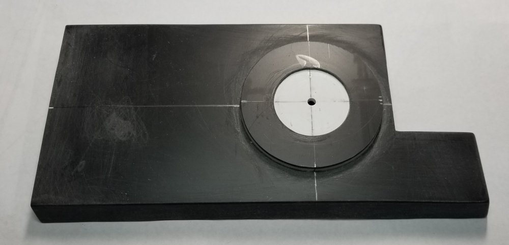
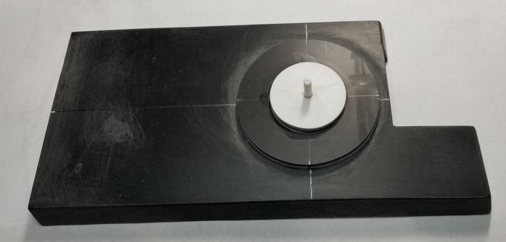
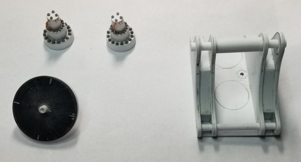
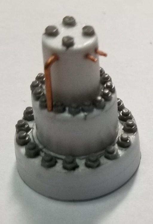
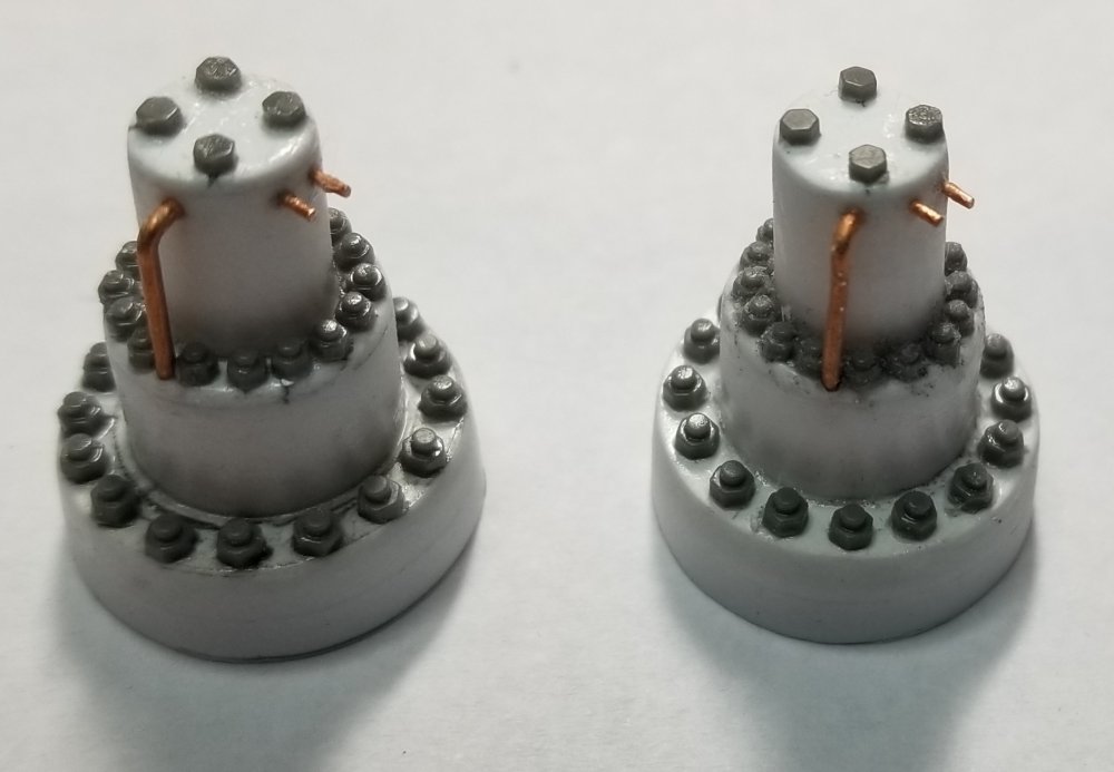
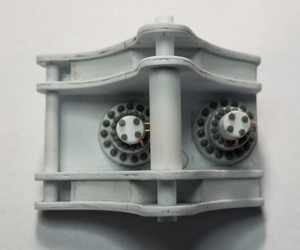
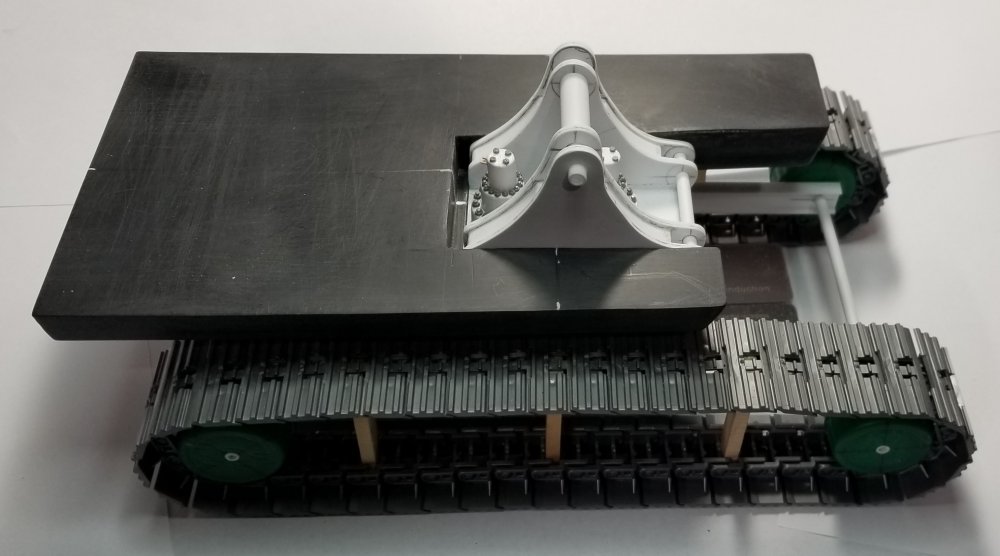
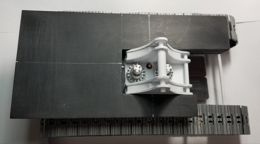
Hey guys Another update for you guys. I've done some more work on the base. I added the main pivot bearing to the bottom of the base. I made it so that it attaches with a 2-56 bolt that will allow it to rotate. I also made the 2 swing motors. this view shows the bottom of the base with the bearing surface added. this view shows the bottom of the base with the pivot pin area for the undercarriage sitting in place. this view shows the boom pivot bracket, the pivot pin part for the undercarriage and the 2 swing motors. this view is of the pivot pin area that will eventually become part if the undercarriage frame. top view of one of the swing motor. side view of the swing motor. this view shows both of the swing motors. I had to grind the bottoms out of some 1/8" thick plastic sheet. The rest is made from 1/2" & 5/16" plastic tube and some 0.03" thick plastic sheet pieces. The bolts are from Meng, 2.2mm and 1.8mm heads, that I had to individually cut off of the plastic piece they come on and install with some CA glue. Sounds complicated but it wasn't that bad. this view shows the swing motors in place on the boom pivot bracket. this view shows the boom pivot in place on the base. top view of the whole thing temporarily sitting on the tracks. Well that's it for now be back with more updates soon. Ron G
-
Hey Mark I have two of these kits. I'm using them to make a Michigan gravel train with a AMT Kenworth W-925 tractor to pull it. But since I'm doing the Cat 374F L, XL Specialized HD130 drop nose lowboy RGN trailer, XL 80 jeep, XL 80 booster/stinger and a Revell Peterbilt 359 heavy haul tractor it's going to have to wait...lol Ron G
-
Thanks guys Ron G
-
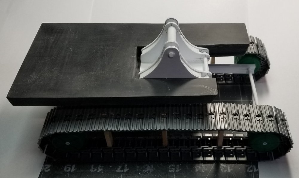
Thanks guys Small update for you. I have the main boom pivot and boom cylinders mounting/pivot bracket done. this view shows the pivot bracket in place on the body base. I also added the main deck to the base. view from the front of the boom pivot in place. I made this from some 0.06" plastic sheet glued to 0.03" plastic sheet in order to get to 0.09" thickness for the 4 sides. In between these I added some 0.04" x 1/4" plastic strips to form the 2 uprights. I glued these to a piece of 0.06" thick plastic sheet to create the pivot bracket. Well that's it for now be back with more updates soon. Ron G
-
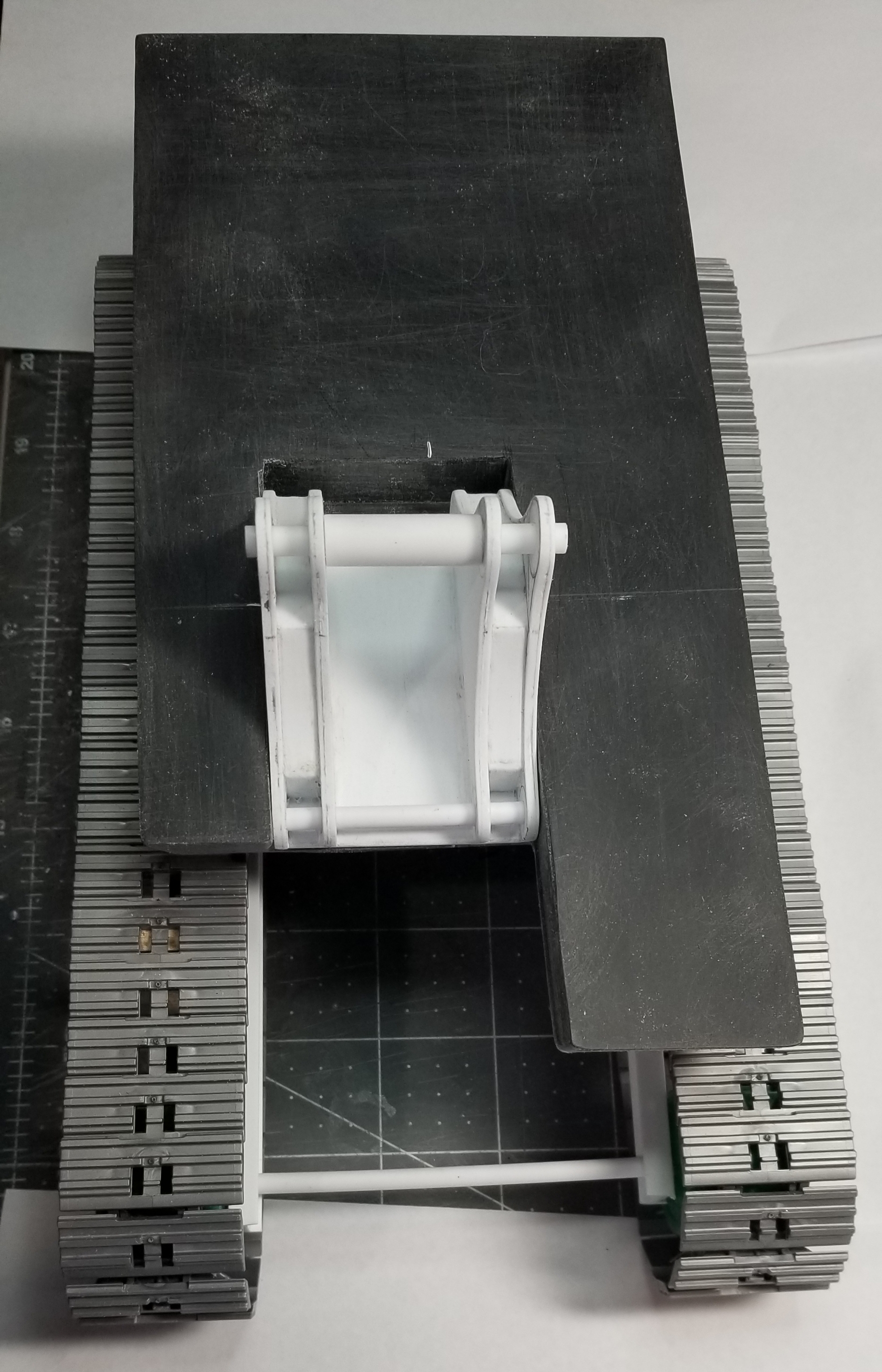
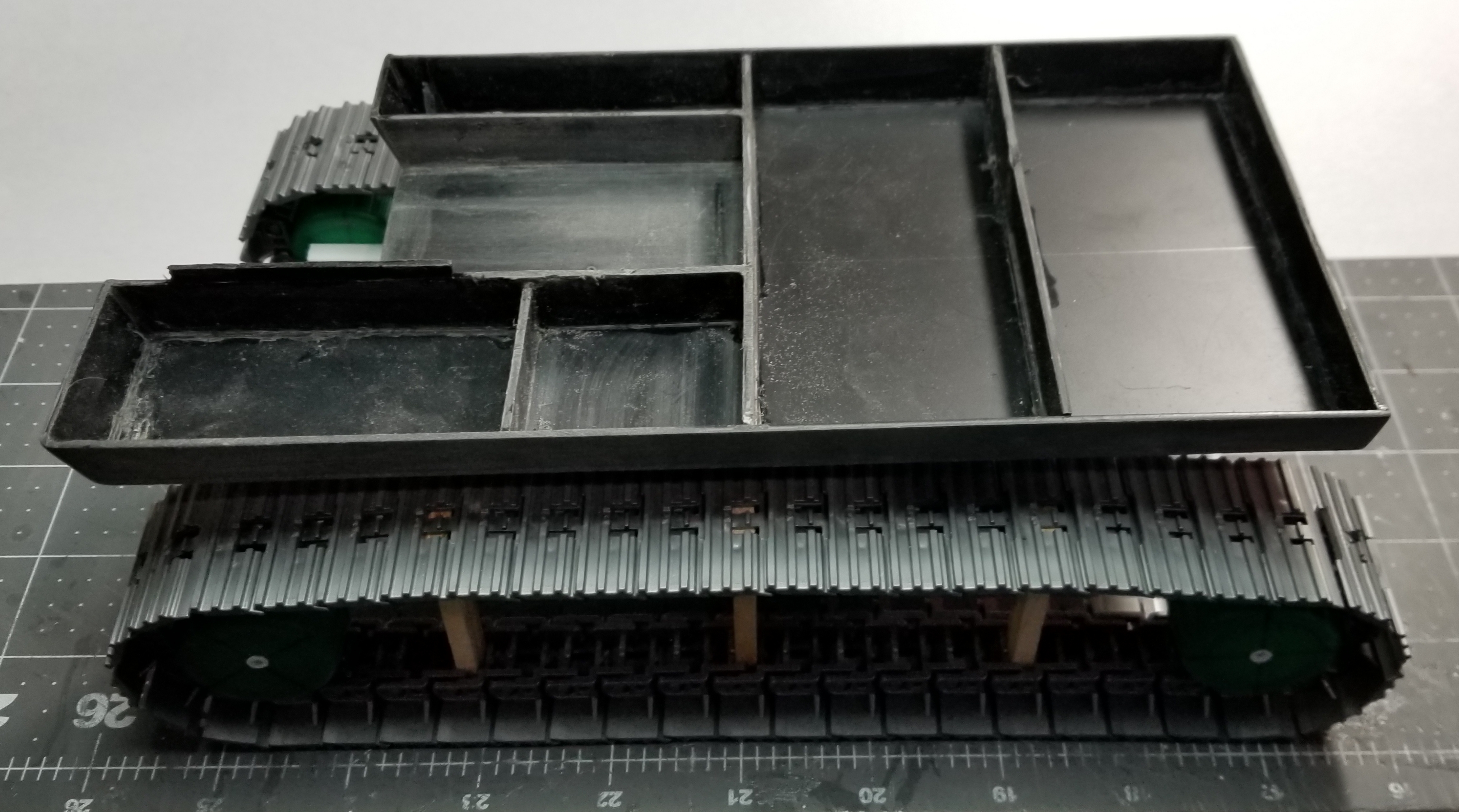
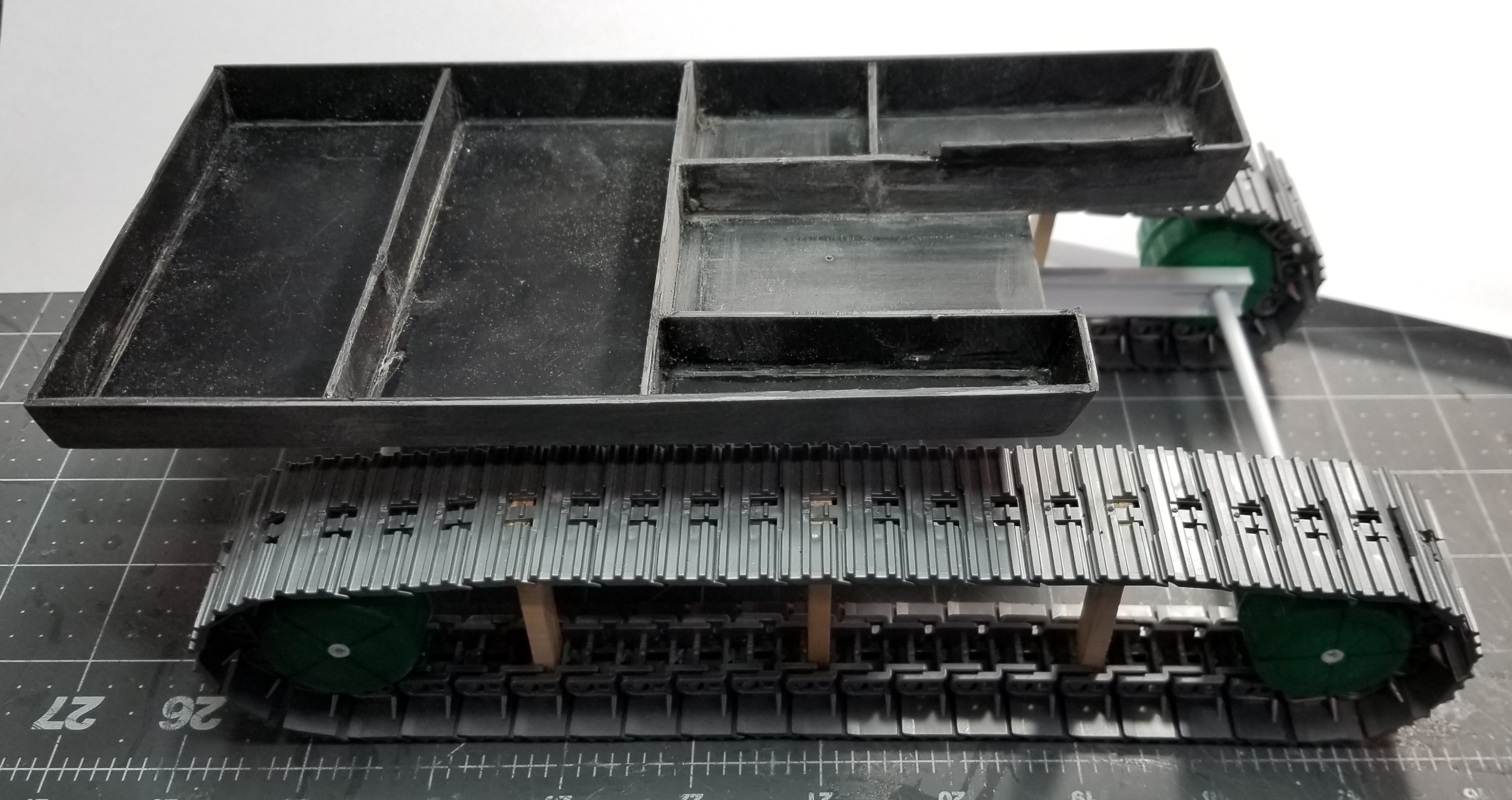
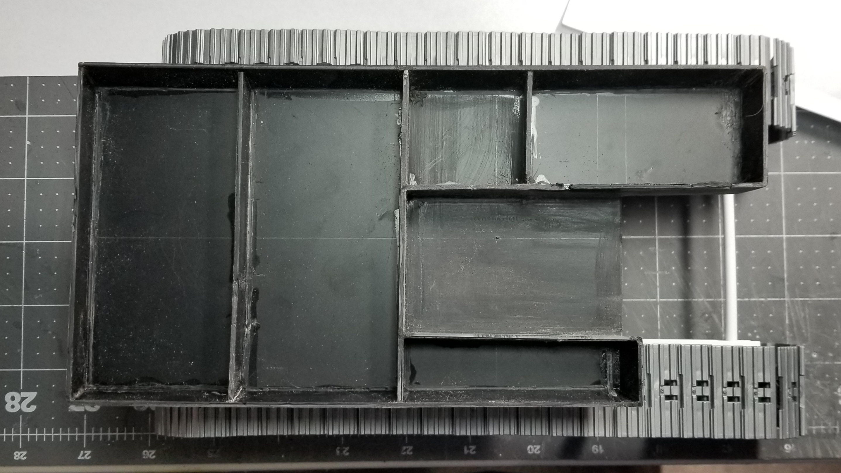
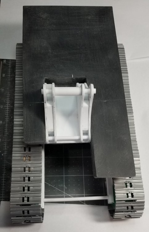
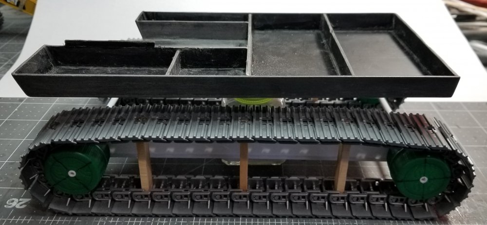
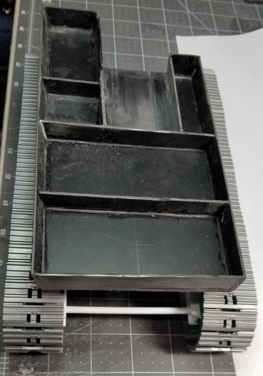
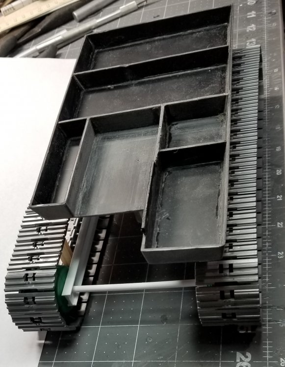
Hey all Small update for you all. I have the bodys base pretty much done. I made it out of some 0.06" thick black plastic sheet. this is a view of the operators side. same view, but more from the side. rear view of the base. view from the front of the base. this view is from the side opposite of the operator. top view of the bodys base. The cab area is in the upper right. The hydraulic tank is on the opposite side at the front. The area in between them is were the boom pivot and boom cylinders will be, also the swing motors will be here too. The rear most area is for the motor and in front of that is were the hydraulic hose stand for the boom and stick will reside. Well that's it for now be back with more updates soon. Ron G


-
Hey Mark I didn't make the tracks, they are from Bruder toys. There a kind of nylony plastic, but definitely workable. Everything else except for the C15 Cat engine will be scratch built. Ron G
-
Thanks Harv
-
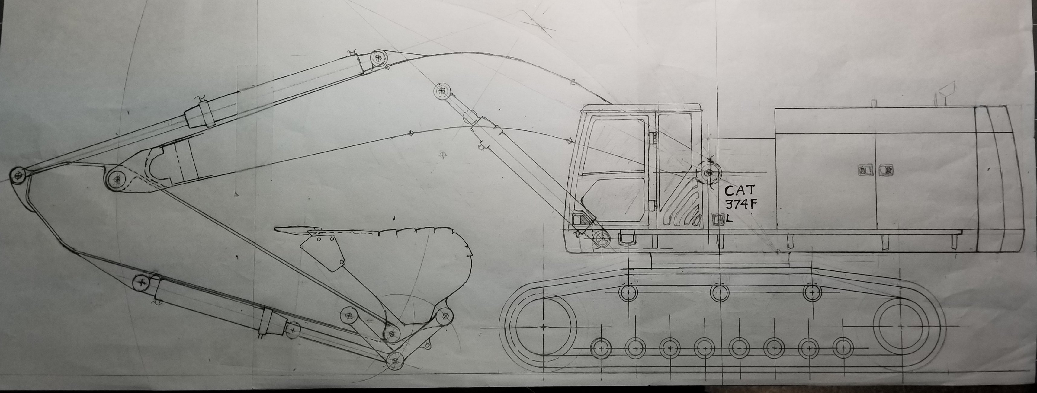
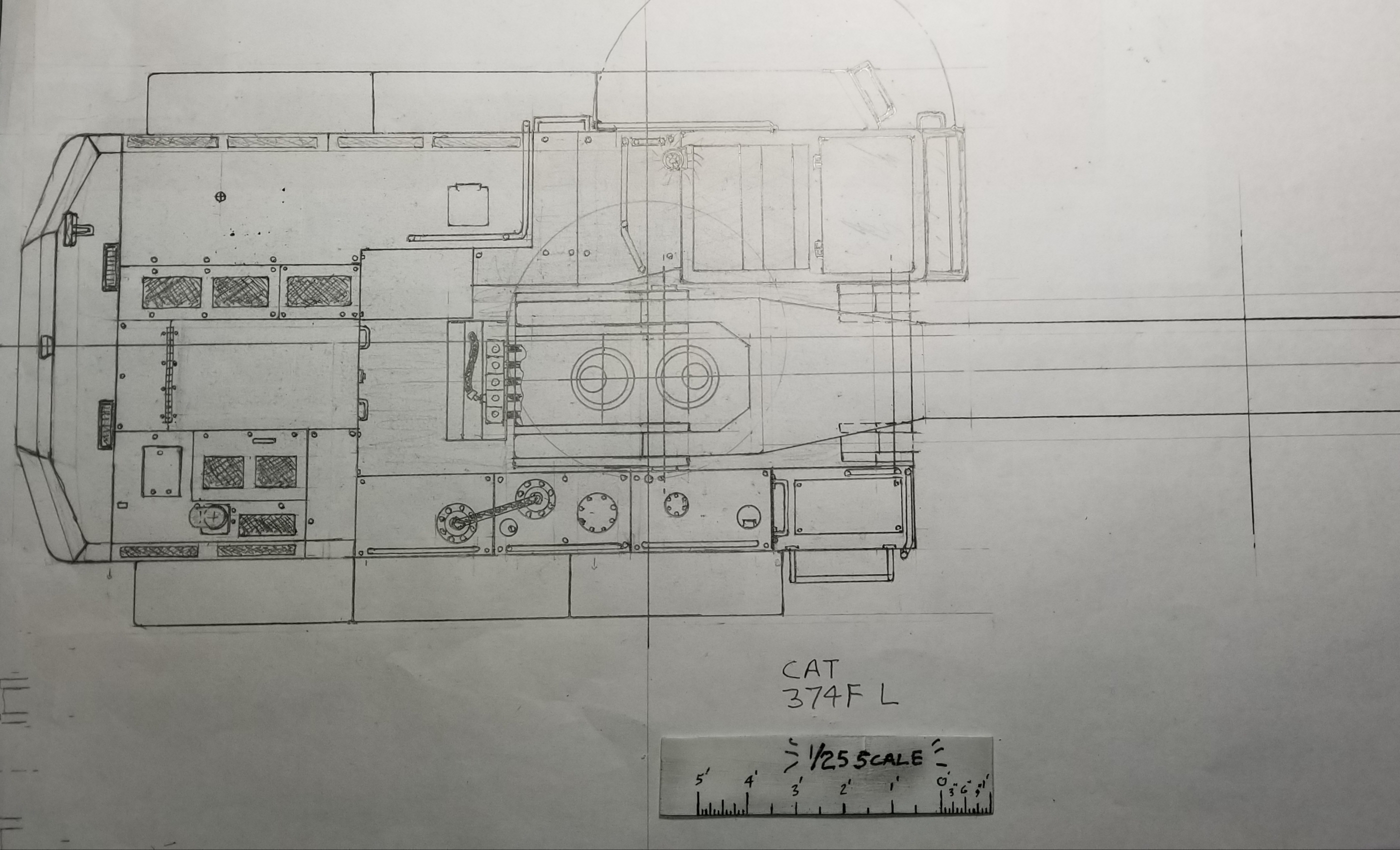
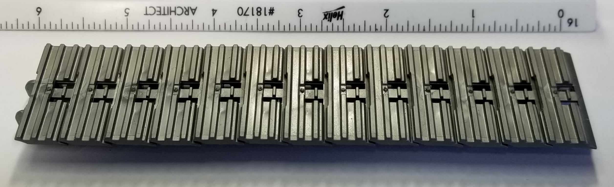
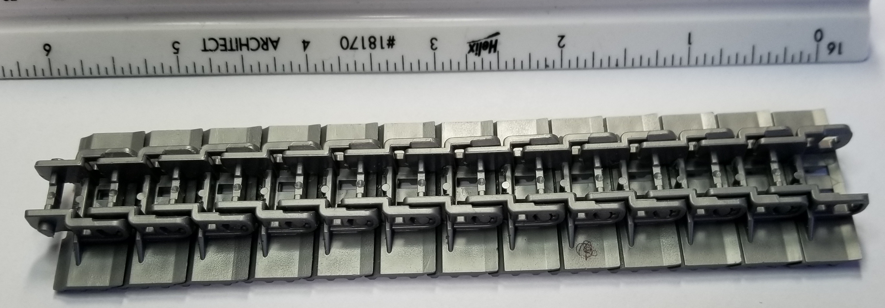
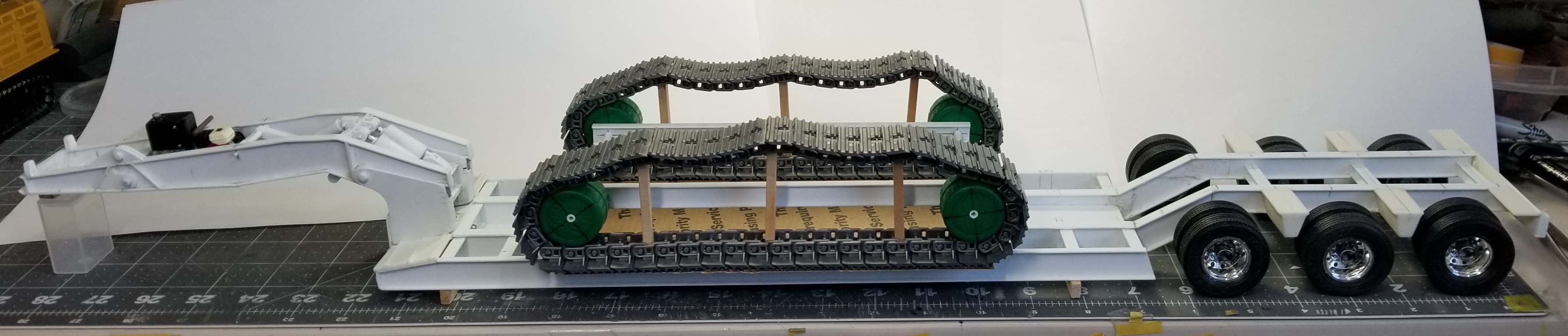
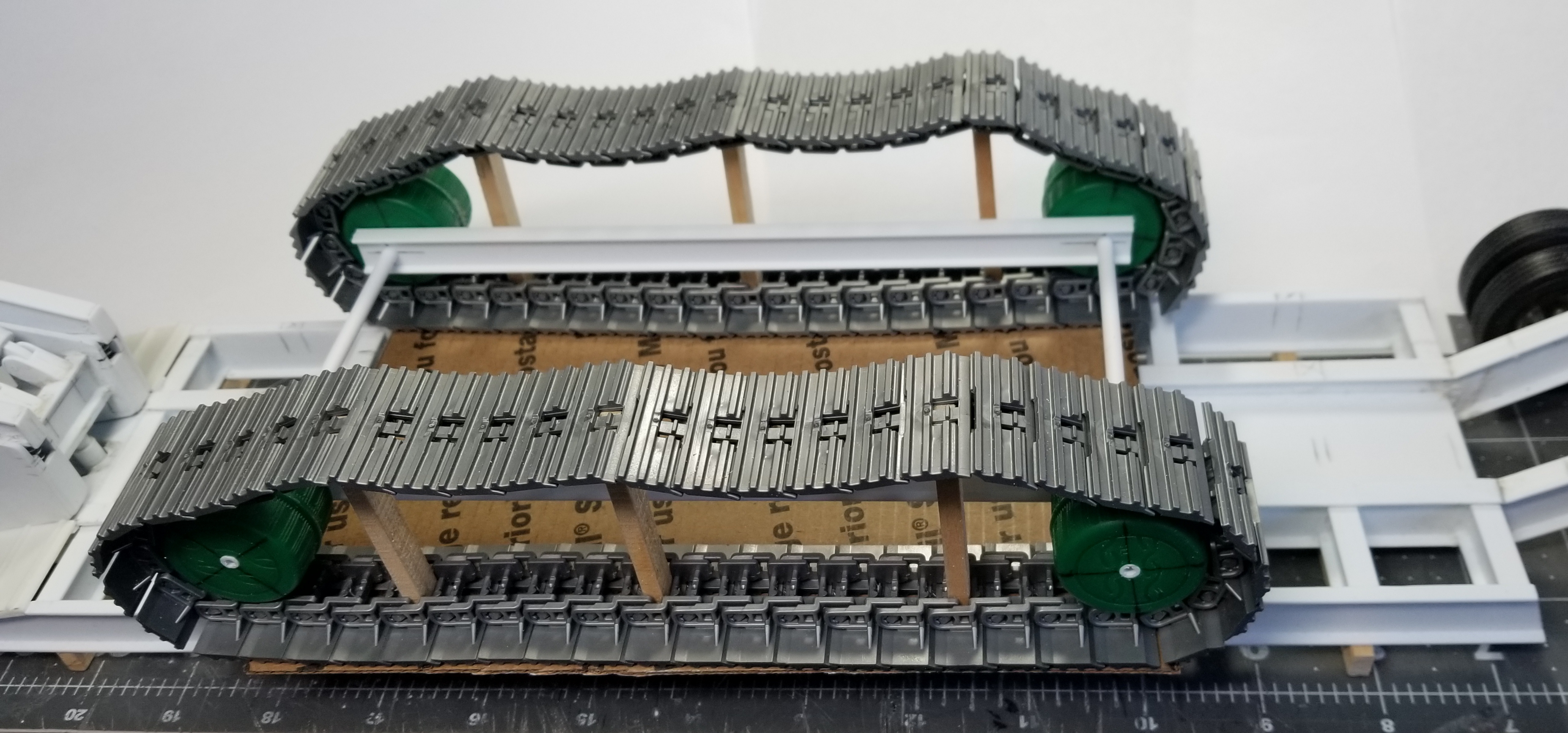
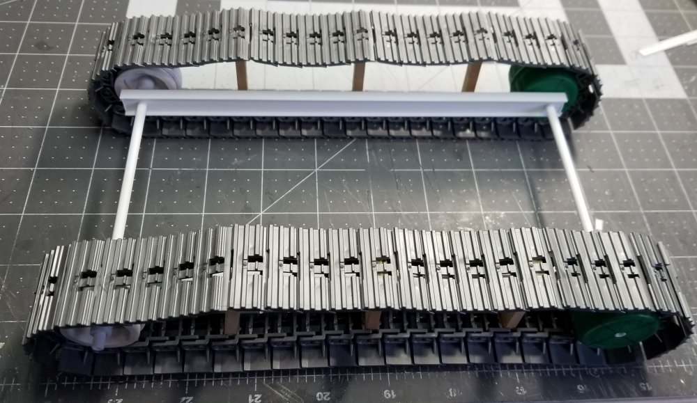
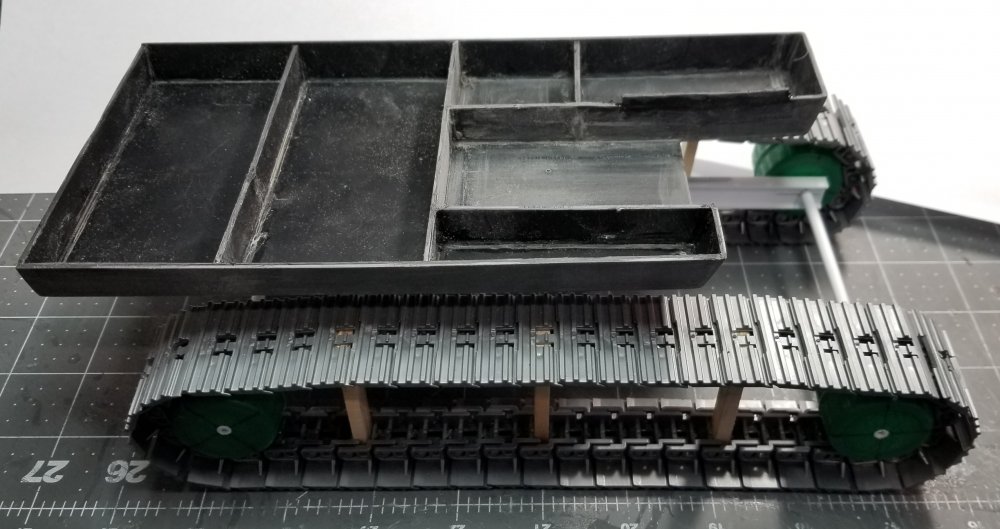
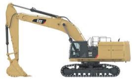
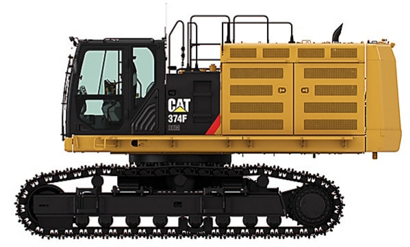
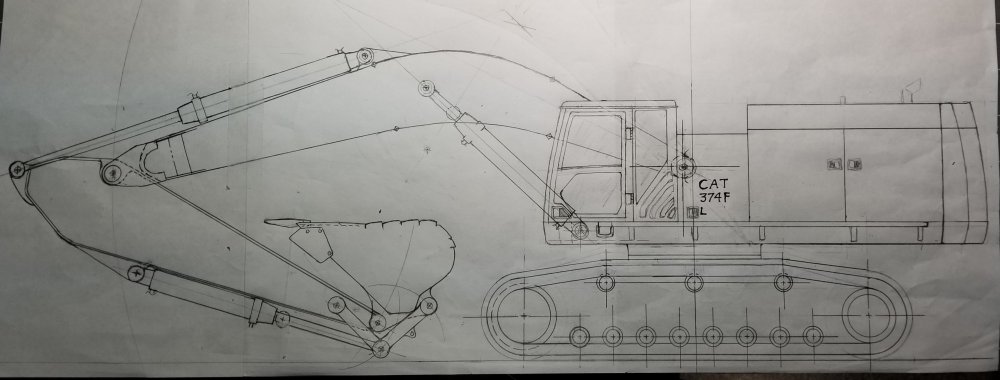
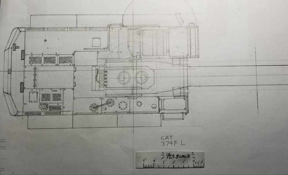
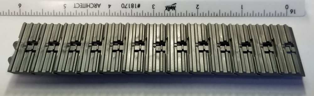
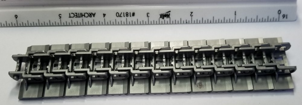
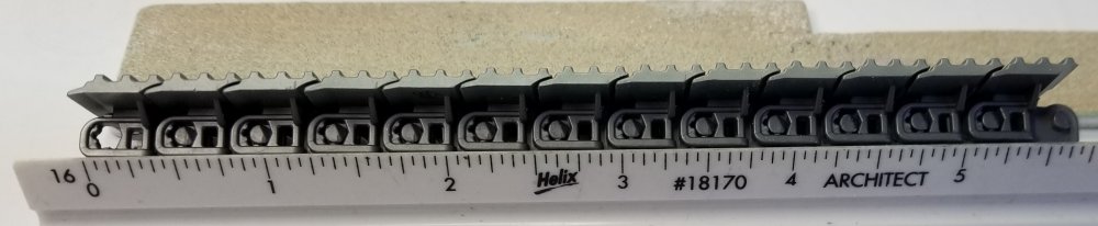
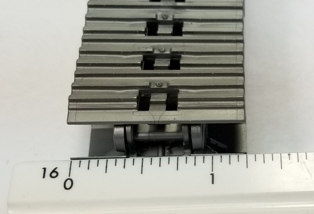
Hey all I'm at it again...lol. yes it's another project. Actually it's a load for my XL Specialized HD130 drop nose RGN lowboy trailer, XL 80 jeep, dual nitrogen charged booster/stinger and Peterbilt 359 heavy haul tractor. It's going to be a Cat 374F L excavator almost completely scratch built. I ordered a Cat C15 resin engine from Moluminum and I'm using some tracks I got from Bruder toys. This view shows the real Cat 374F L. This view shows a closer look at the body of the excavator. this view shows my scale drawing of the big Cat 374. this is a plan view of the big Cat. I don't have all the pictures of the 374 that I need, but I do have a 1/50th scale Cat 390F L and a Cat 349F L to use for references. here is a view of the Bruder tracks. These are actually for there mini excavator in 1/16 scale, but work out perfect for the big Cat 374. view of the other side of the tracks. side view of the tracks. end view of the tracks. They work out to be 1.25" wide which is 31.25" in 1/25th scale or 30" in 1/24th scale. this is my temporary undercarriage setup that I made to figure out all the geometry. more of a top view of the tracks. I have a feeling that this is going to take quite a while to get finished, but I'm plugging along...lol. well that's it for now be back with more updates soon. Ron G

-
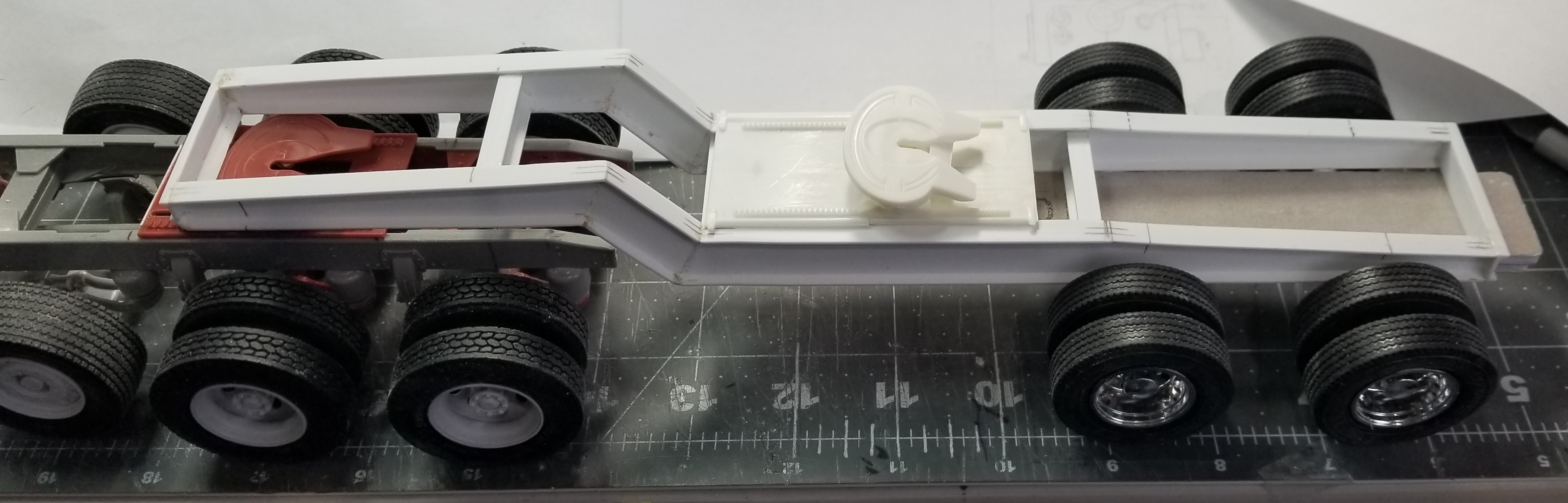
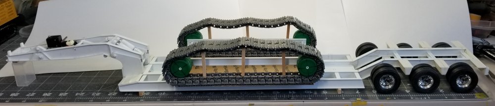
Hey guys Kind of a update, but not. I'm starting another project. Before you all go WHAT!!! it's a load for the XL 130 HD drop nose lowboy trailer. I'm going to start a new post for it. It's going to be a Cat 374F L large excavator. here is the temporary undercarriage sitting on the trailer. more of a top view of the tracks. These are from Bruder toys, there for there mini excavator, but are perfect for the Cat 374F L. So check out my post on this new project. Ron G


-
Thanks guys
-
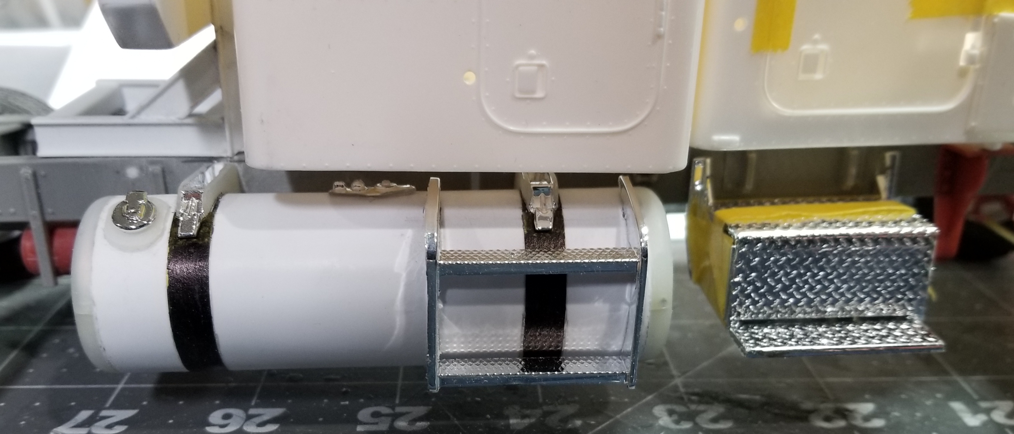
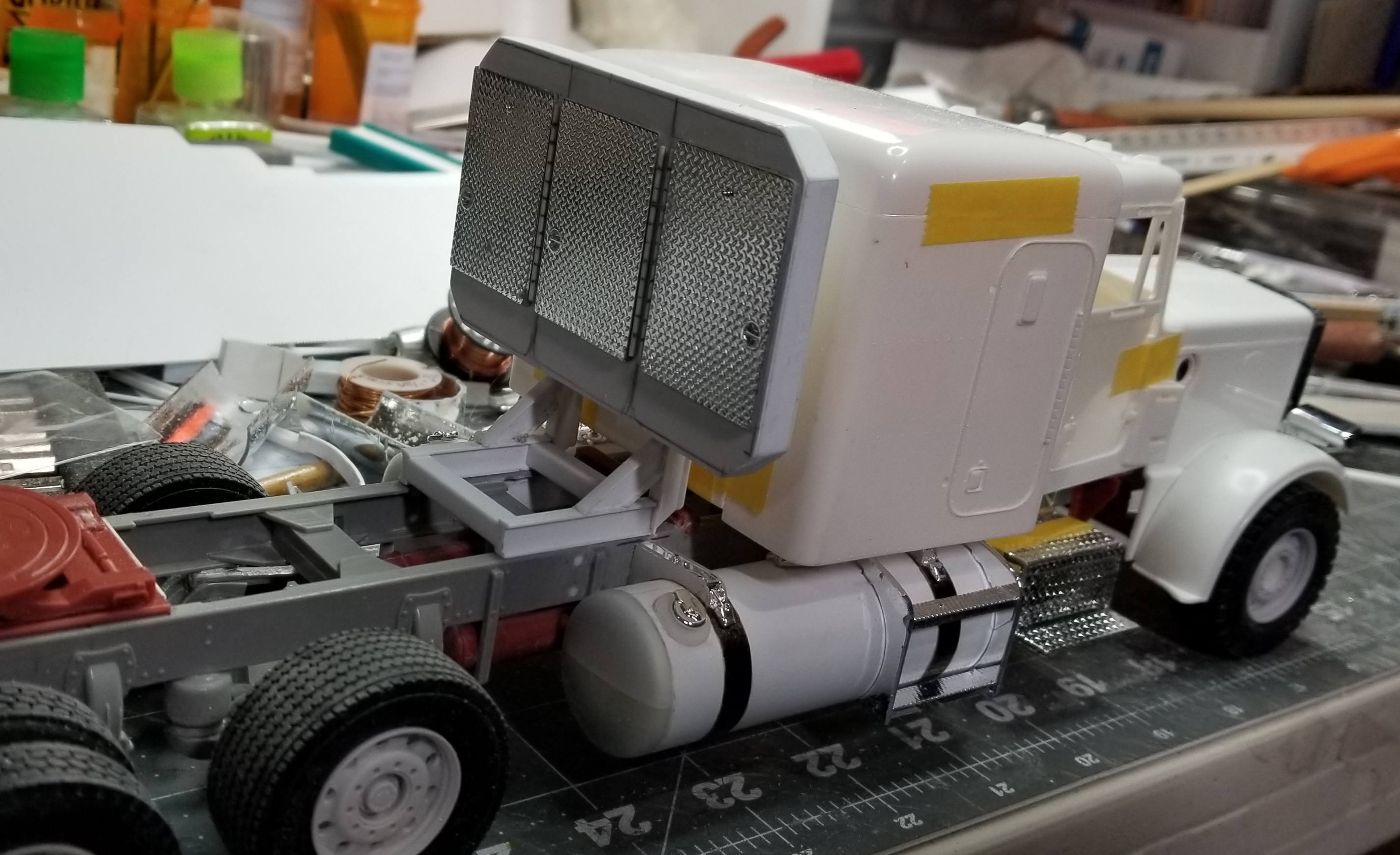
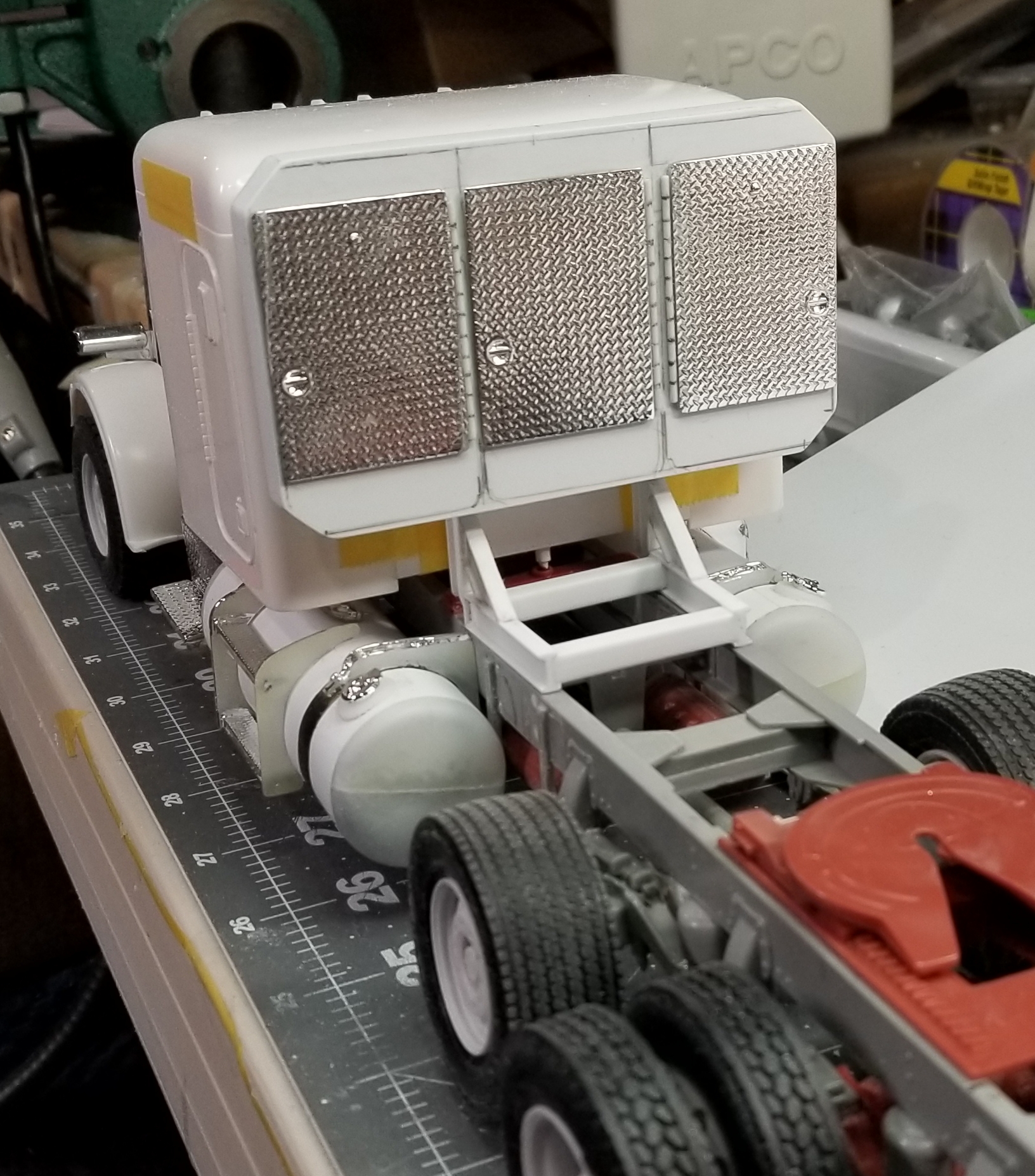
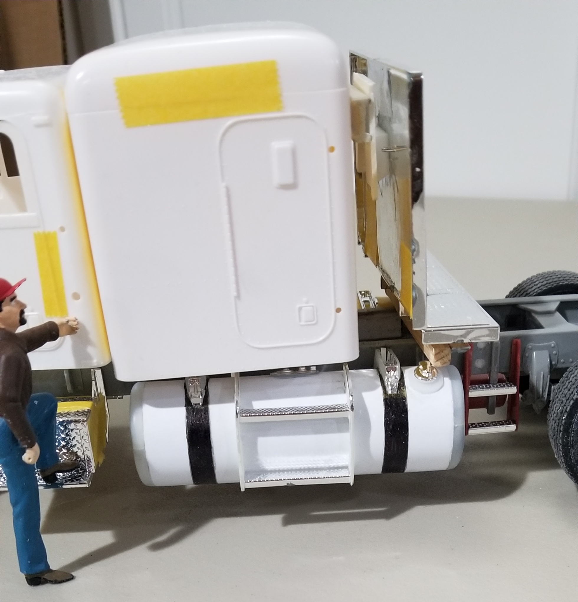
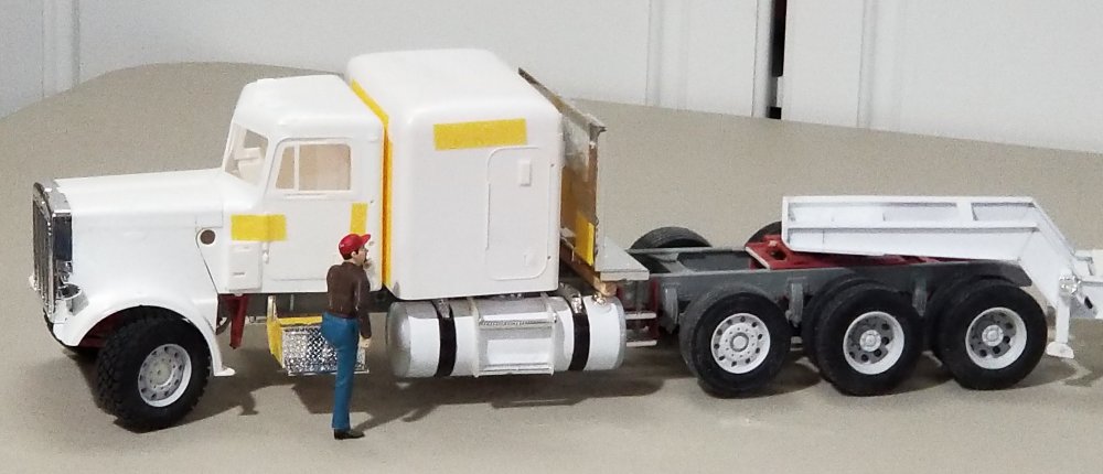
Hey guys Small update, I finished the passenger side fuel tank and reworked/scratch built a new headache rack. this view shows the passenger side fuel tank with steps. this view shows the whole truck and tank. this view shows the tank from the front. this view shows the new headache rack. this view shows the whole truck and headache rack. rear view of the headache rack. this view shows the driver side fuel tank. Well that's it for now be back with more soon. Ron G


-
Thanks Chris
-
Hey Mark Yes and no, I actually have this drawn/modeled up on Cad in Unigraphics NX16. I also drew some scale plans on paper. I was a draftsman for near onto 35 years, then transitioned onto Cad, so the drawing comes easy, plus I've been modeling building since I was around 7 years old (I'm now 70) Ron G
-
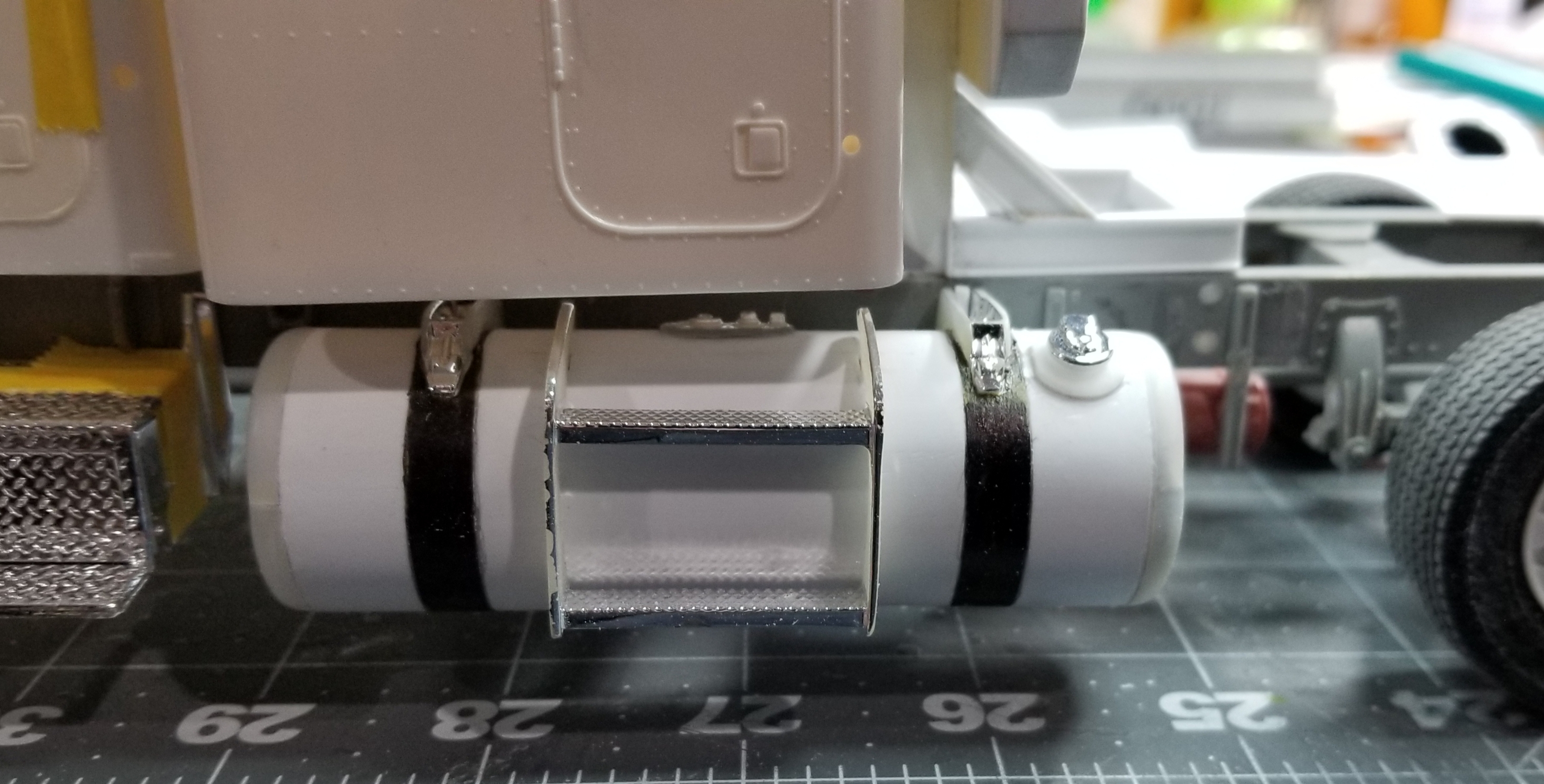
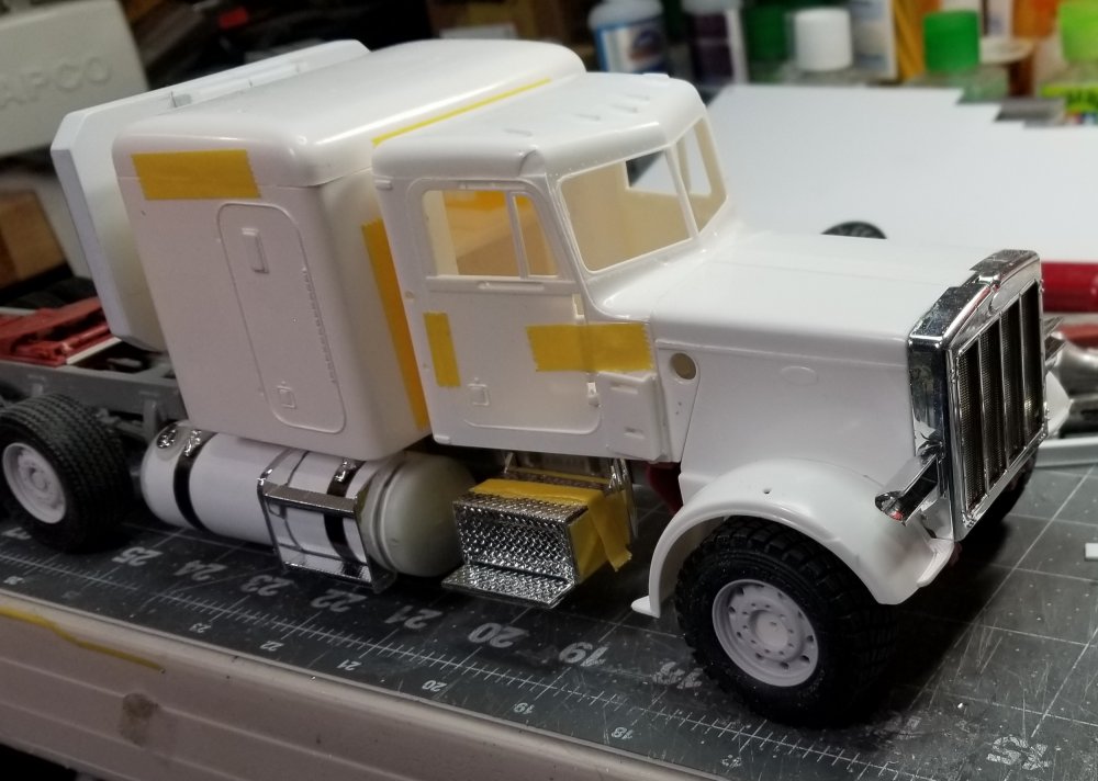
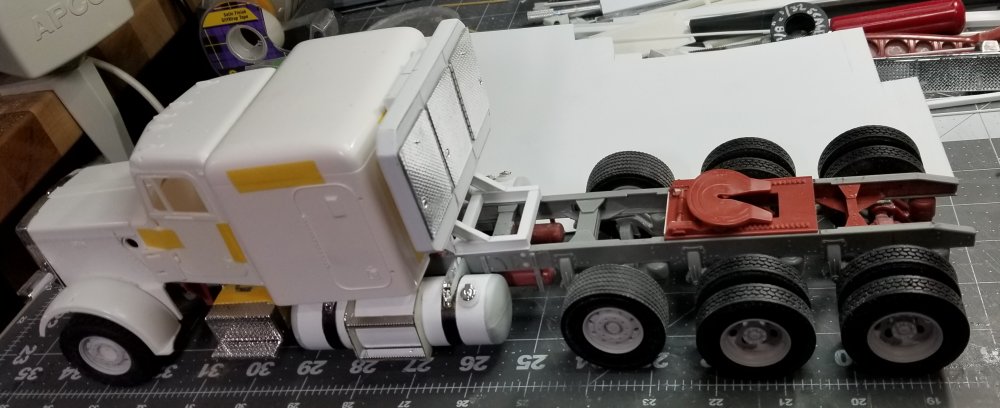
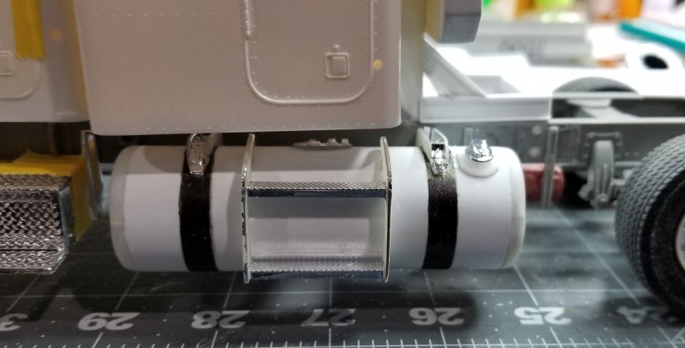
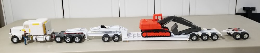
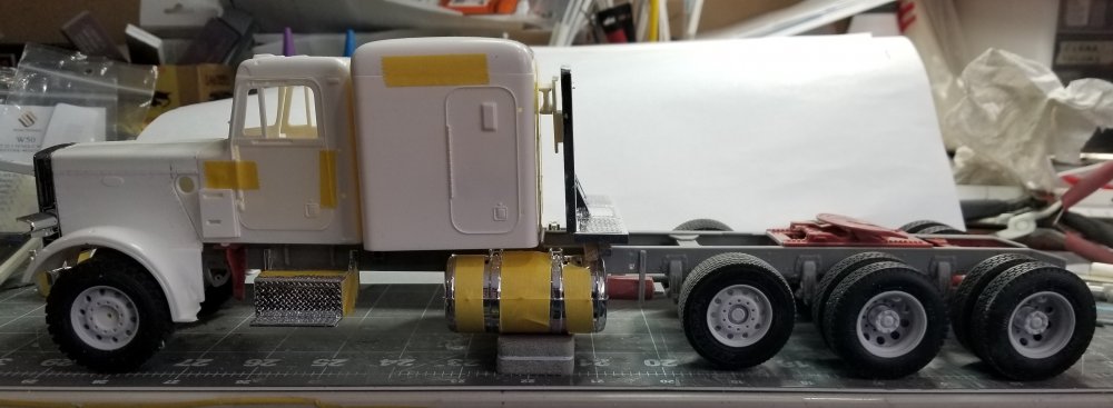
Hey all I did some work on my Peterbilt 359 heavy haul tractor. I made a new 28" diameter x 90" long 200 gallon fuel tank. I still need to do the passenger side tank. this view shows the tractor and the new tank. this view shows a closer look at the tank and steps. I made this from a piece of 3/4" pvc pipe that is 1.07" diameter. I Wrapped some 0.03" plastic sheet around the pipe to make it 28" diameter. I cut up the original tank that came with the kit to use the parts on my new tank. I put the whole thing together temporarily to show how big it is. YICKS!!! It's big! The excavator is a 1/32 scale Newray one and the booster/stinger is actually the dolly for my Michigan gravel train project. Ron G

-
Thanks Jeff
-
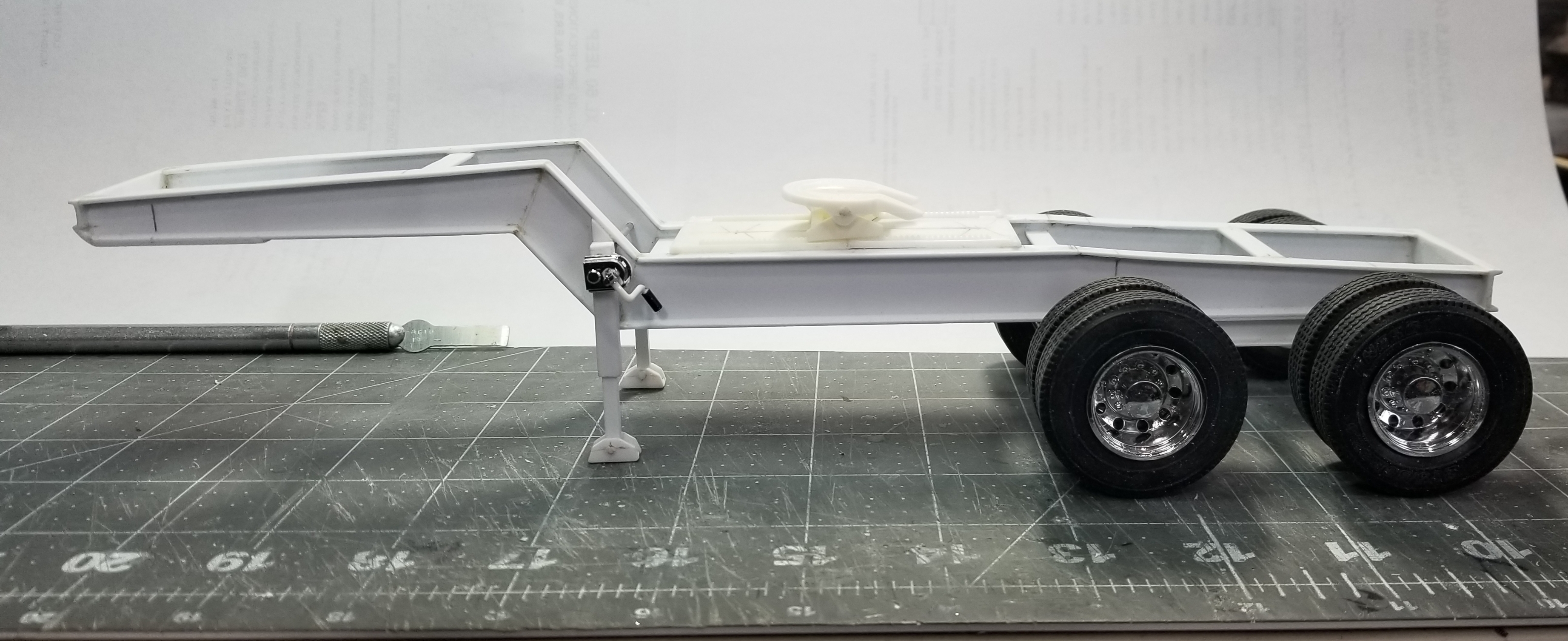
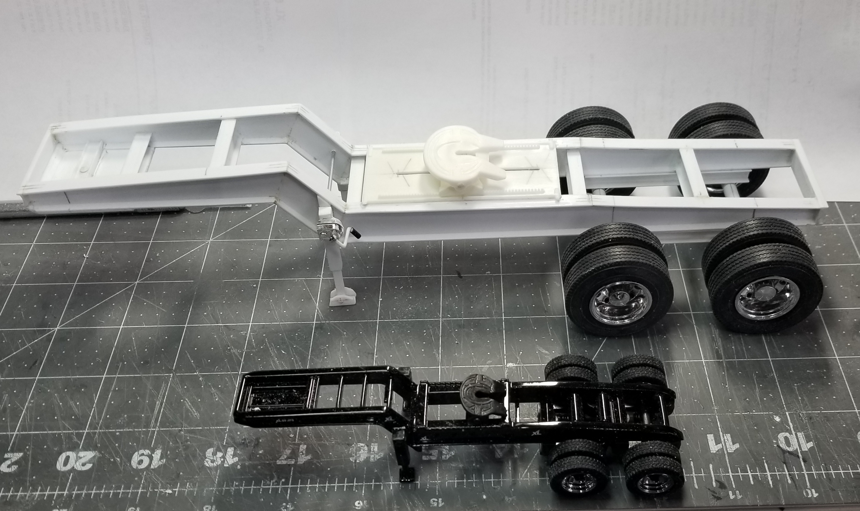
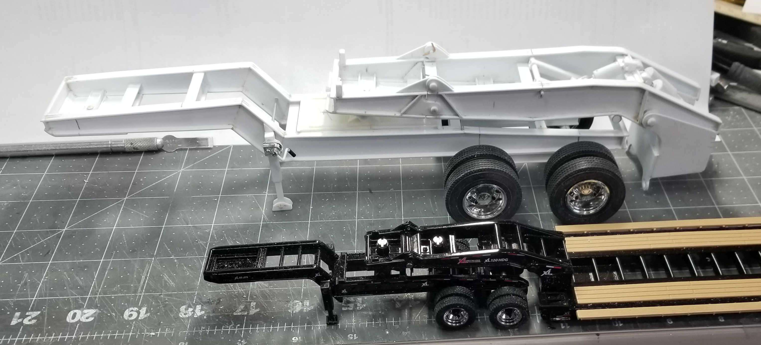
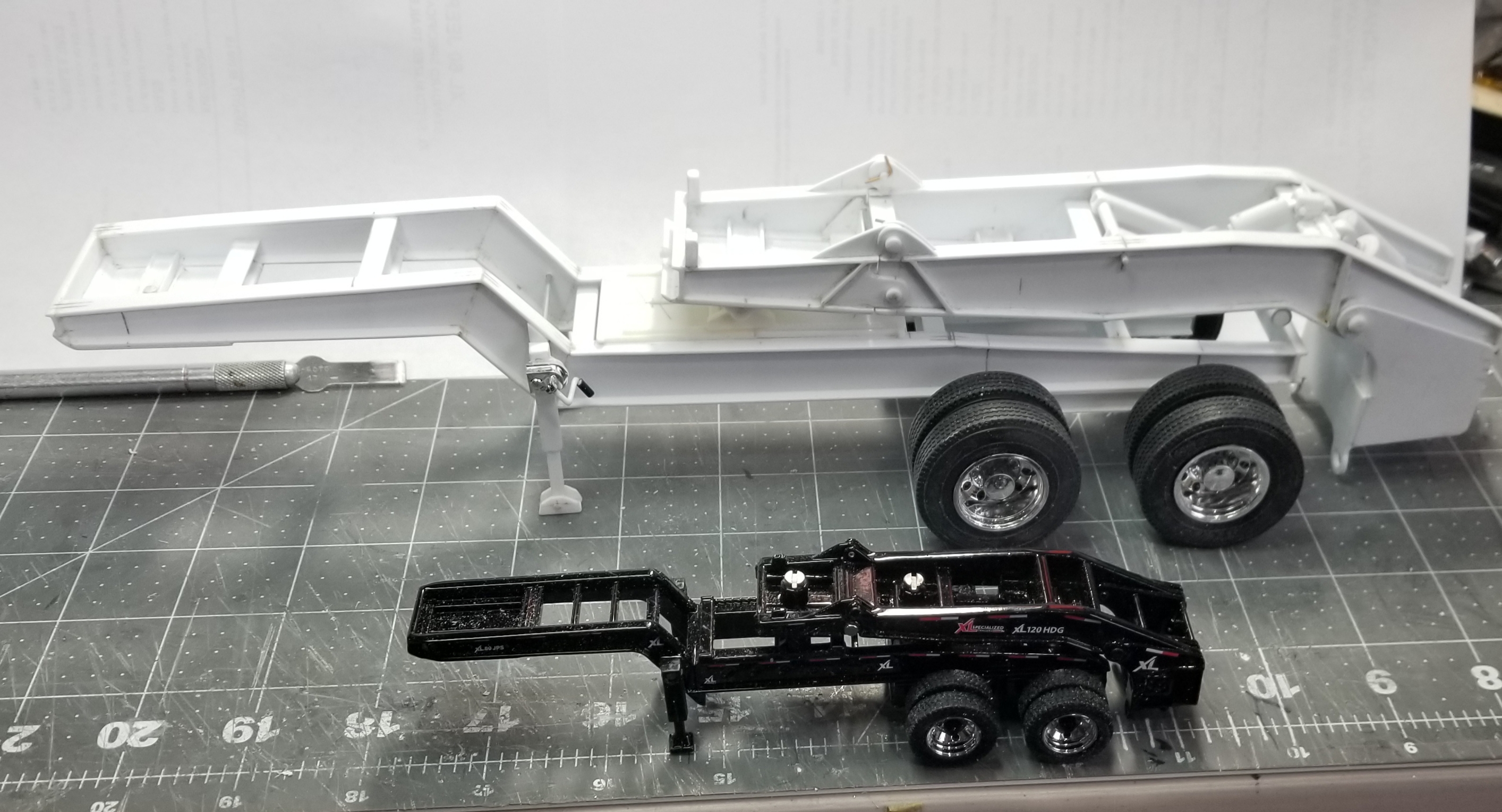
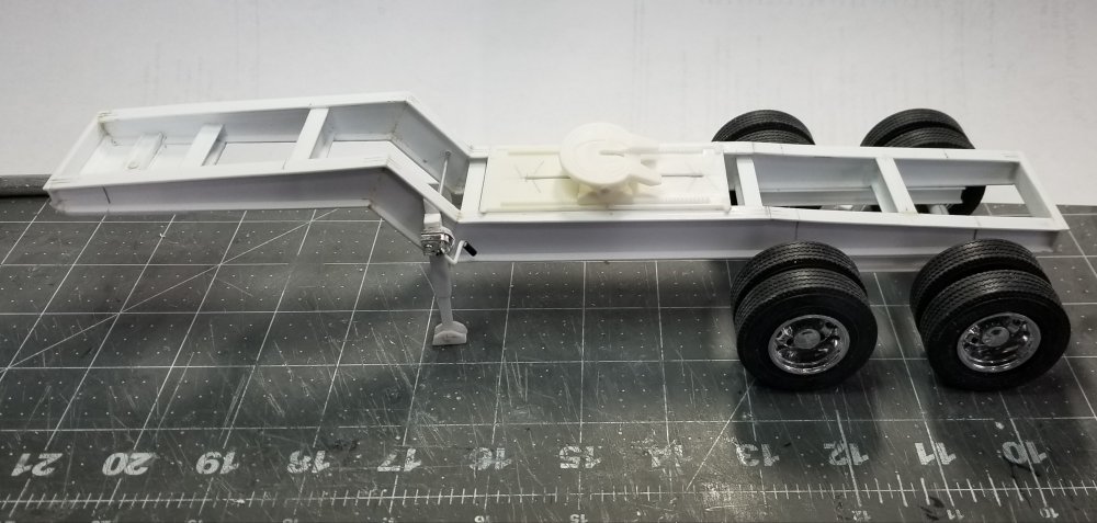
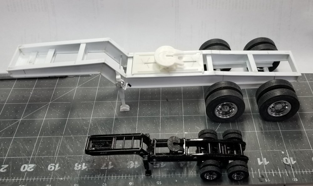
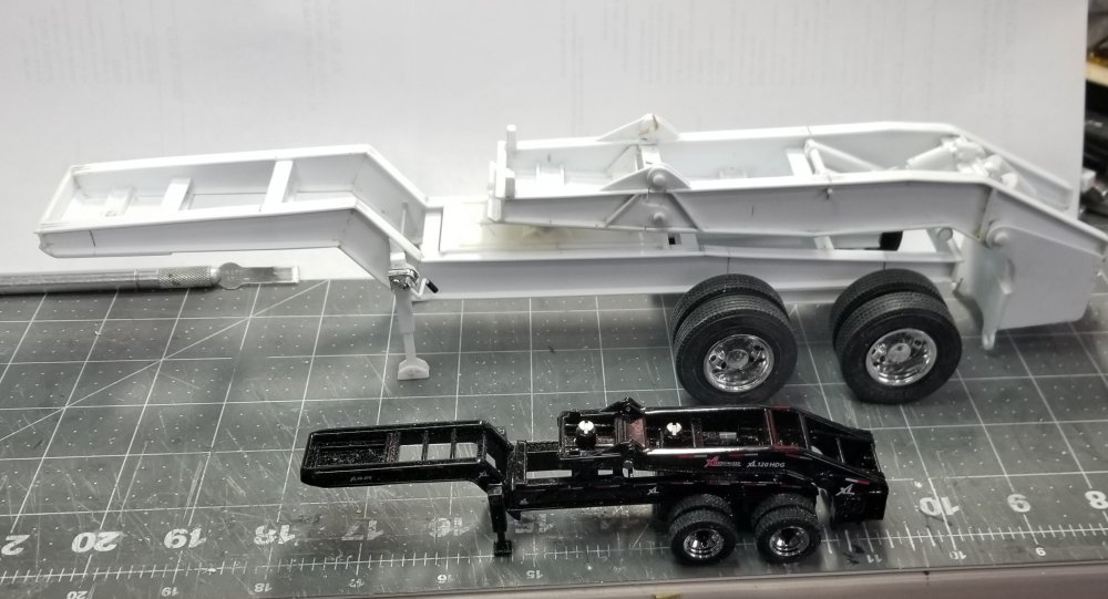
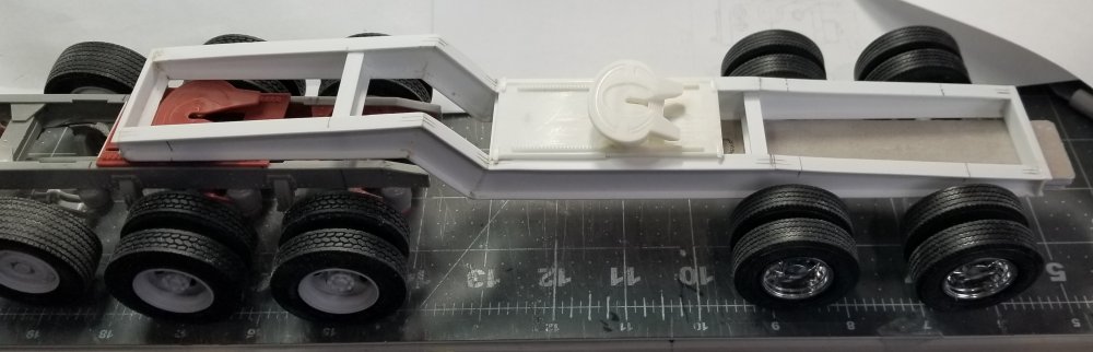
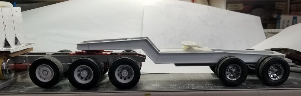
Hey all I did some more work on the XL 80 jeep. I have the landing legs made and installed on the jeep. I used some parts from the AMT twin trailer (Consolidated Freight) kit to make the legs. I installed the fifth wheel plate and the fifth wheel permanently to the jeep. I made it movable for/aft, but still fixed to the jeep. I made a temporary axle set up for the jeep, so I could get the legs right. this view shows the XL 80 jeep with the legs and fifth wheel installed. side view of the jeep. this view shows my XL 80 jeep next to the Diecast Masters version in 1/50th scale. this view shows my jeep with the gooseneck sitting on it and the 1/50th scale version bellow it. this view shows my 1/25th scale jeep and gooseneck with Diecast Masters 1/50th scale version bellow it. Well that's it for now be back soon with more updates. Ron G


-
Yupp, it sure will Ron G
-
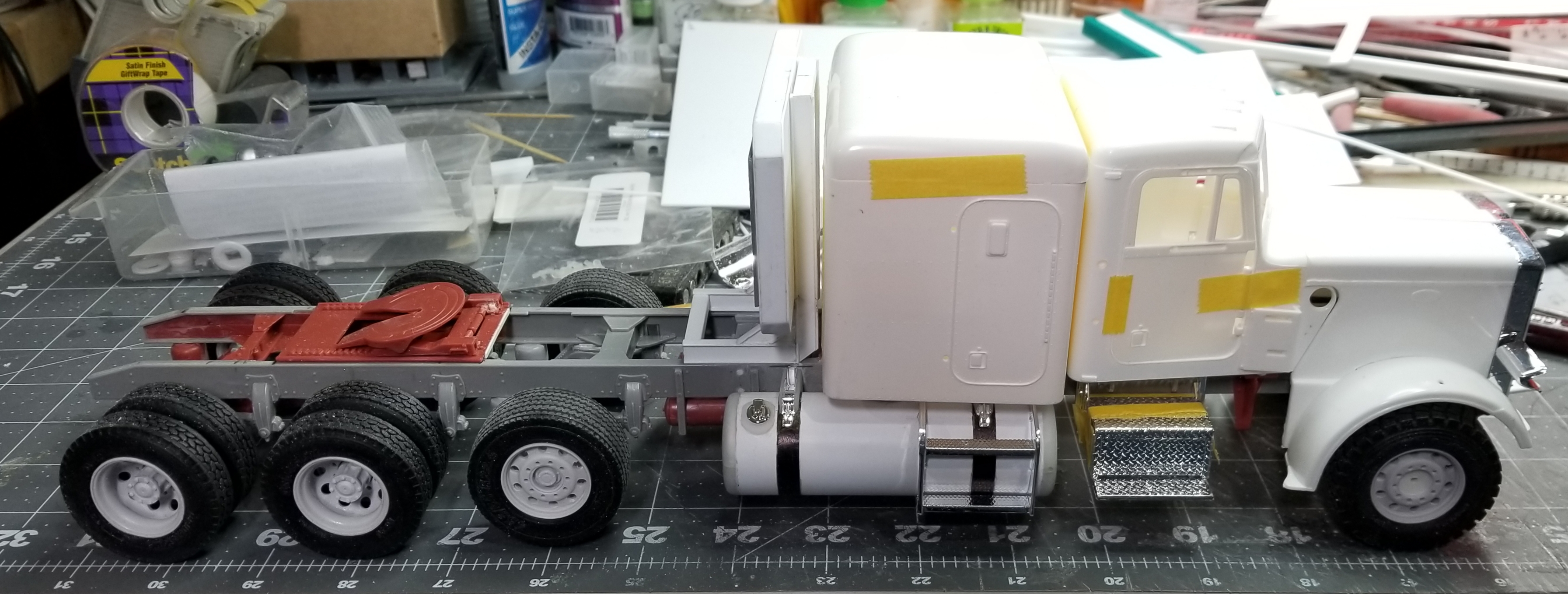
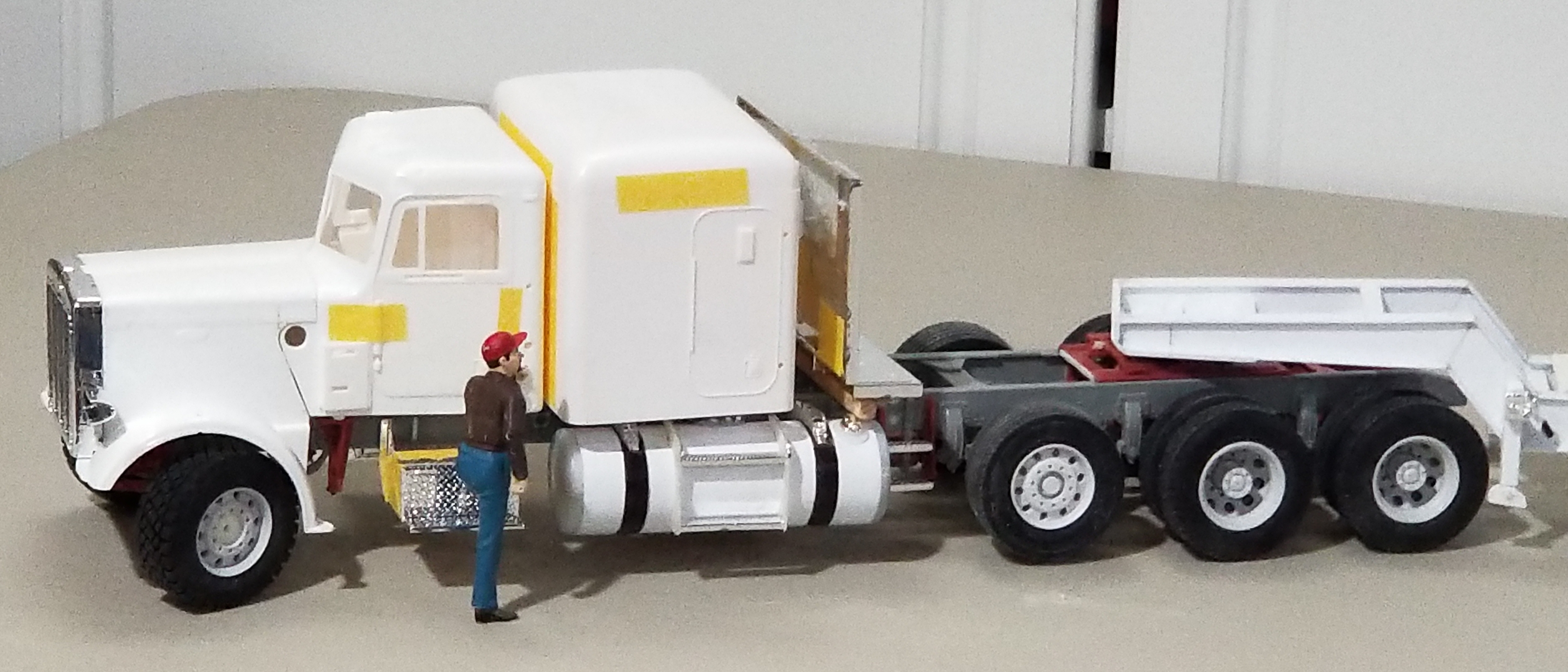
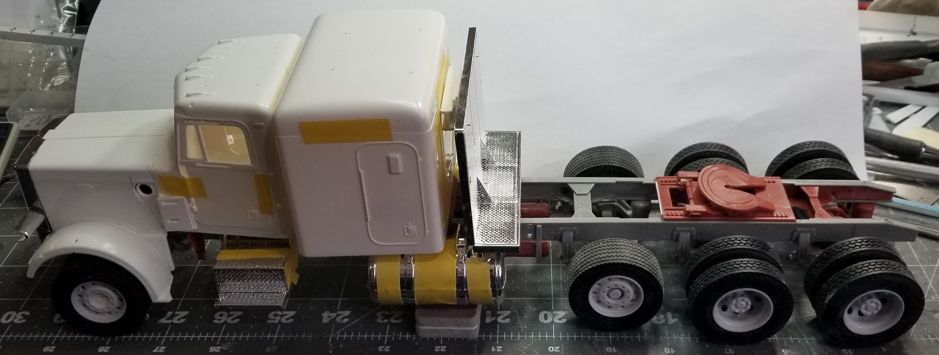
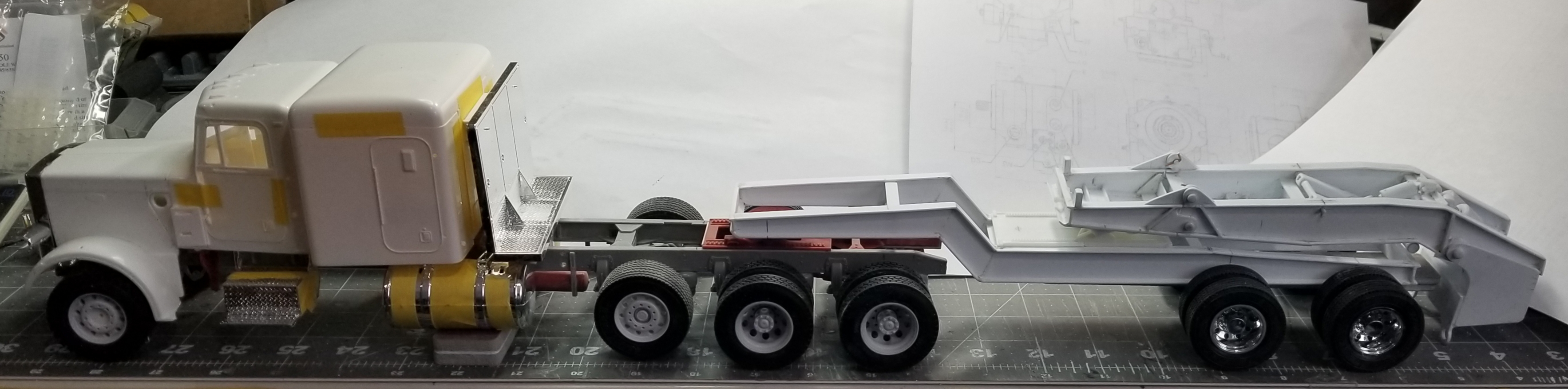
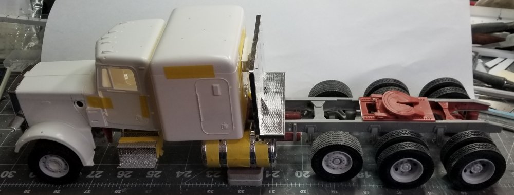
Hey all Ok, I shortened it to a 280" W/B. I think it looks right know. this view shows it with the headache rack in place, this will be modified to look more correct. The fuel tank is sitting in a position to represent where the rear of the new 200 gallon fuel tanks will be.They will be 28" diameter x 90" long. I'm going to make them from some 1" PVC pipe, that is actually 1.125" diameter, 28" in 1/25th scale. this view is more of a side view of the tractor. I also started on making the XL 80 jeep. I decided to go with a two axle jeep instead of a three axle one. The loads I have for the trailer aren't quite large enough to justify a 3 x 3 x 3 so it's going to be a 2 x 3 x 2 set up. this view shows the tractor, jeep and gooseneck of the trailer. this view shows the jeep in its beginning stage. side view of the rear of the tractor and the jeep. Well that's it for now be back with more soon. Ron G

-
Thanks guys