CrankyCrafstman
-
Posts
1,350 -
Joined
-
Last visited
Content Type
Profiles
Forums
Events
Gallery
Everything posted by CrankyCrafstman
-

HK Models 1/32 Lancaster Hints, Tweaks and Tips,
CrankyCrafstman replied to NigelR32's topic in Modelling Discussion
WOW! Those look really sweet. Ron G -
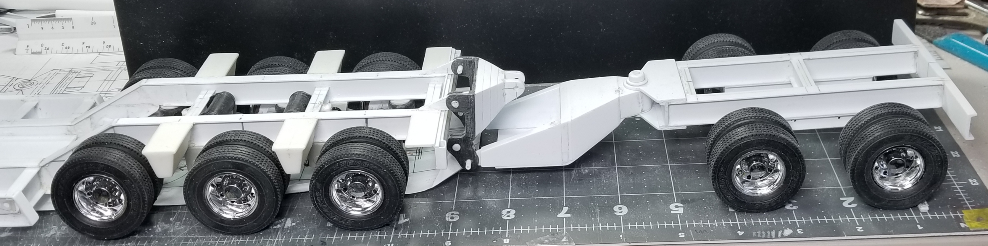
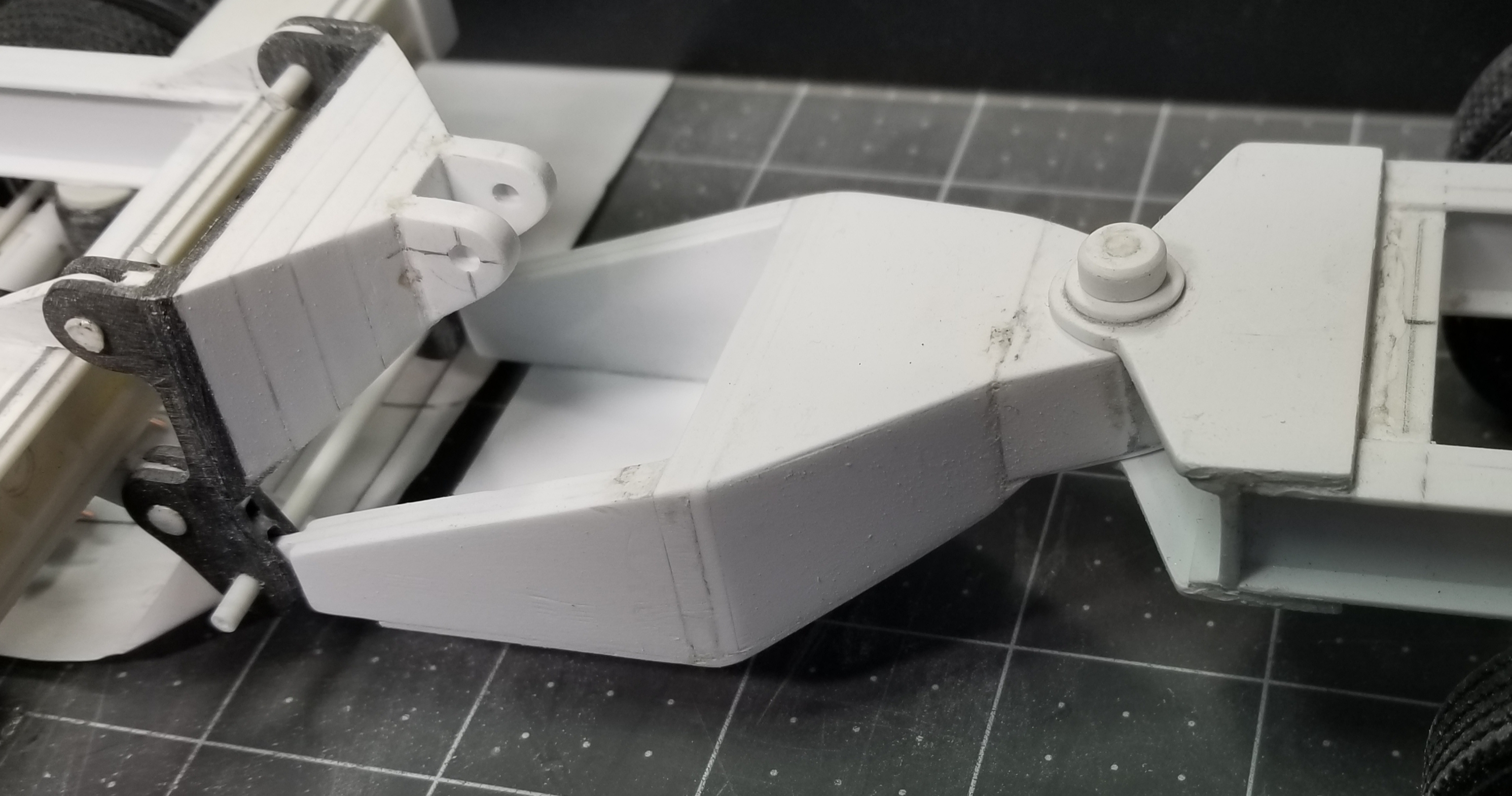
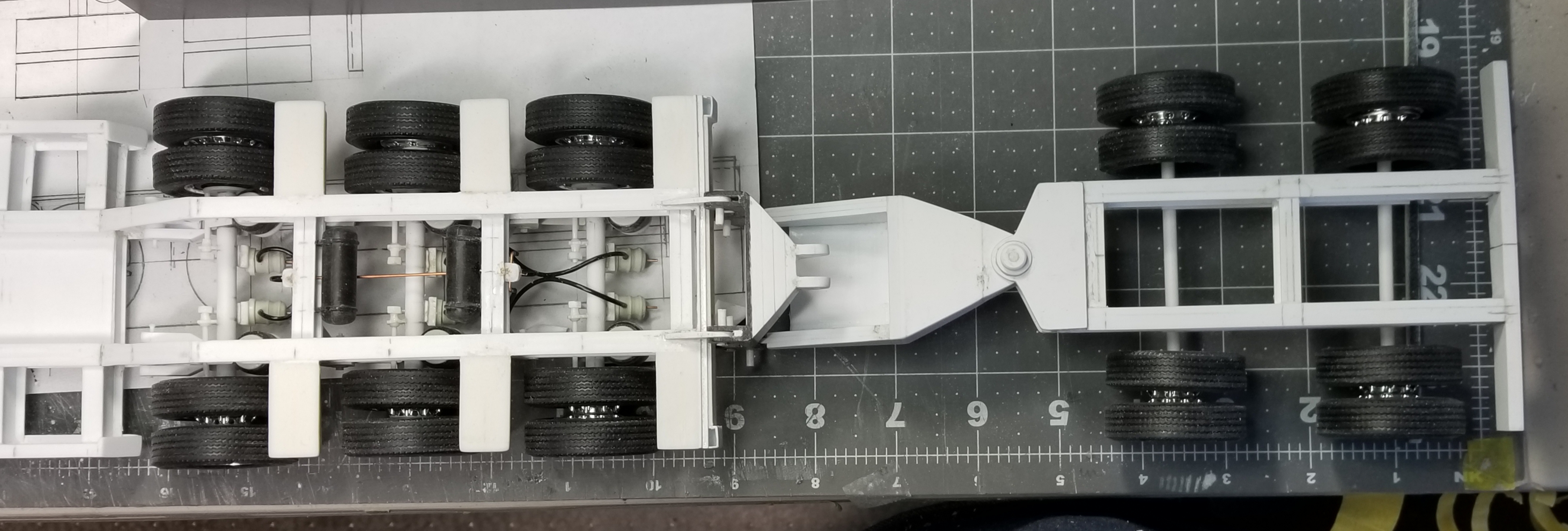
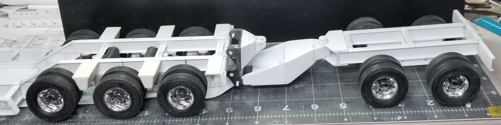
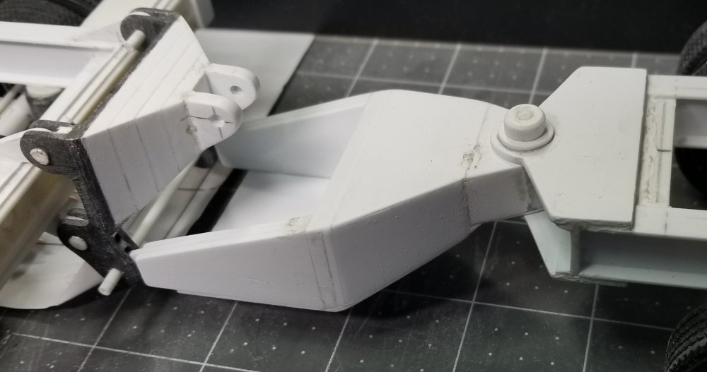
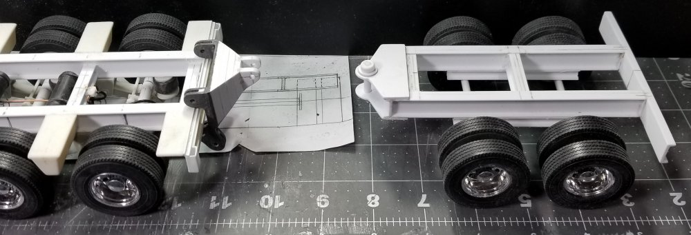
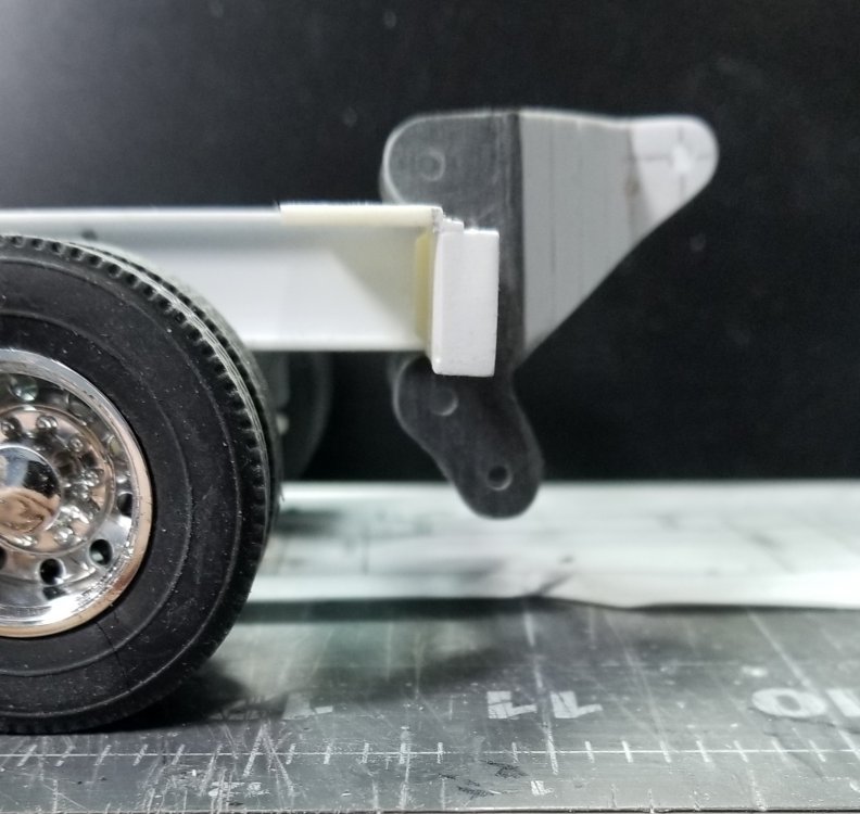
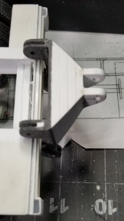
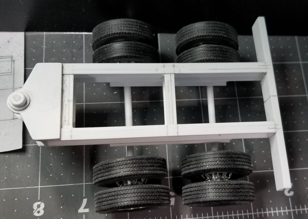
Hey guys I now have the bracket that goes from the mounting bracket to the booster/stinger pivot point. I still need to create the cylinder, nitrogen chamber and attachment mechanism. this view shows the rear of the trailer, mounting brackets and the booster/stinger. this view shows the mounting bracket and the attachment point for the hydraulic cylinder. top view of the whole set up. Well that's it for now be back soon. Ron G

-
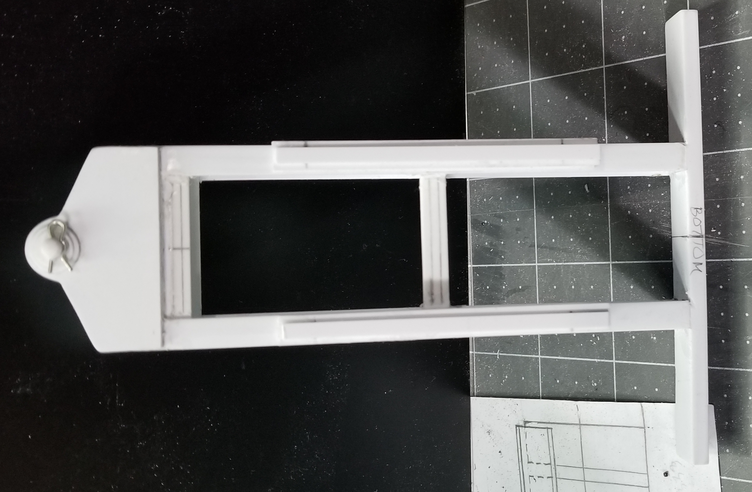
Hey all I started on the XL 42 PMB booster/stinger. Its a nitrogen charged hydraulic one. This allows you to adjust the ride height and load on the trailer. this view shows the booster/stinger and the mounting bracket that attaches it to the rear of the trailer. I need to make the bracket that attaches to the lower pivot on the mounting bracket and the upper attachment point for the hydraulic cylinder, also it attaches to the pivot pin on the booster/stinger. this view shows the mounting bracket. I still need to add the attachment points to the trailer. this shows the mounting bracket from the top. this view shows the beginnings of the booster/stinger and the pivot pin at the front. this view shows the booster/stinger from the bottom and the pivot pins keeper pin. There's a lot of work that still needs to be done. I'm waiting on air suspensions for it from Moluminum. Well that's it for now be back soon with more. Ron G

-
What is on your bench right now ? Share a picture :)
CrankyCrafstman replied to Martinnfb's topic in Modelling Discussion
Hey Hubert that looks fantastic, any chance on getting a copy of it in 1/24th scale, or better yet a copy of the digtal file so I can work on it in Unigraphics NX16 and then print it on my 3D resin printer? I need it for my 1/24 DeHaviland beaver kit thats on hold because of the motor...please Ron G -
Got it, thanks Ron G
-
Hey Jeff Please I would appreciate any help you can give. I have no real knowledge of how the brakes work, I've been going by pictures that I have gotten from the internet. Ron G
-
Thanks guys Jeff are you talking about the rods prtruding from the rear of the air chambers? If so how much should be sticking out? Ron G
-
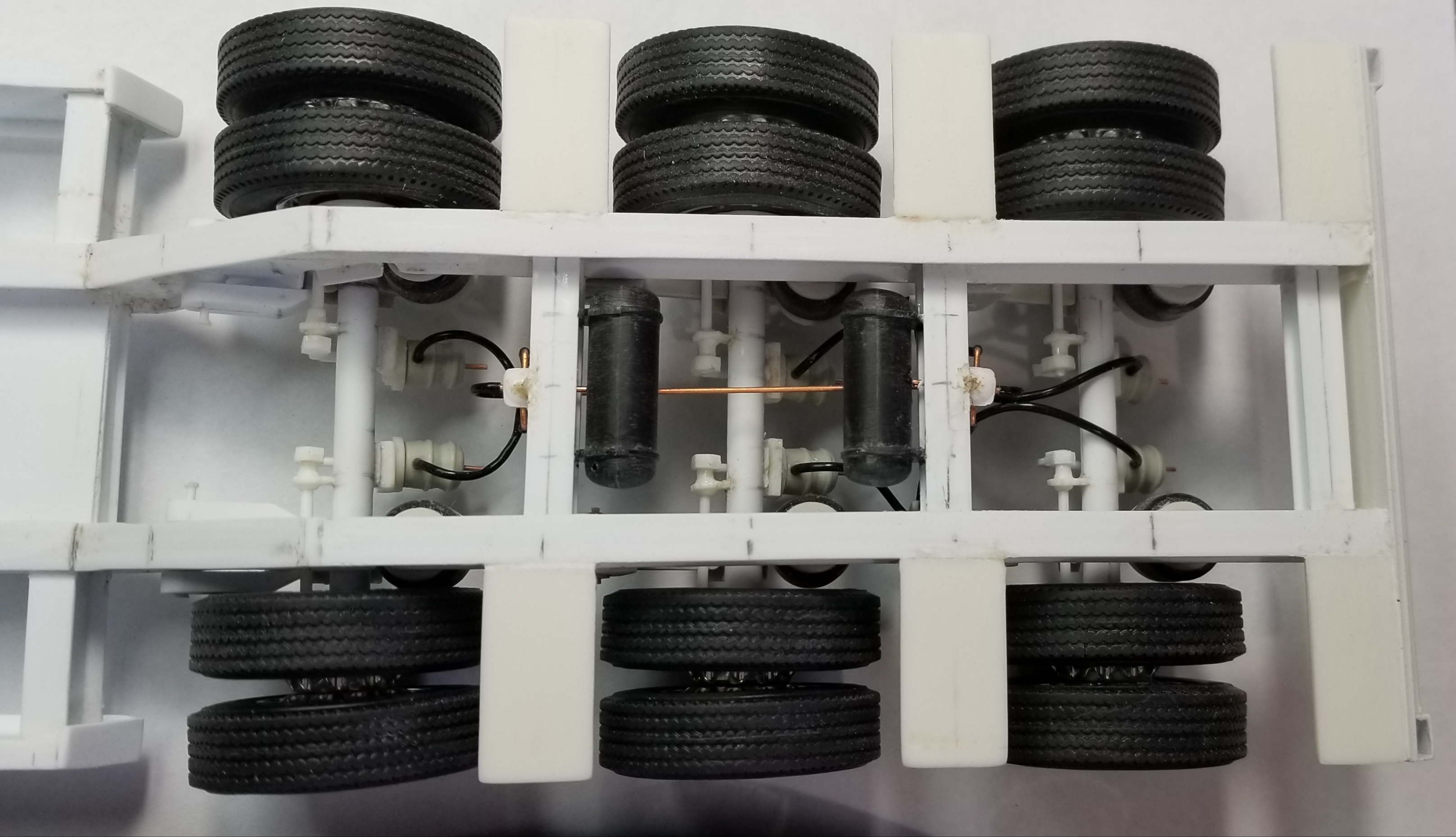
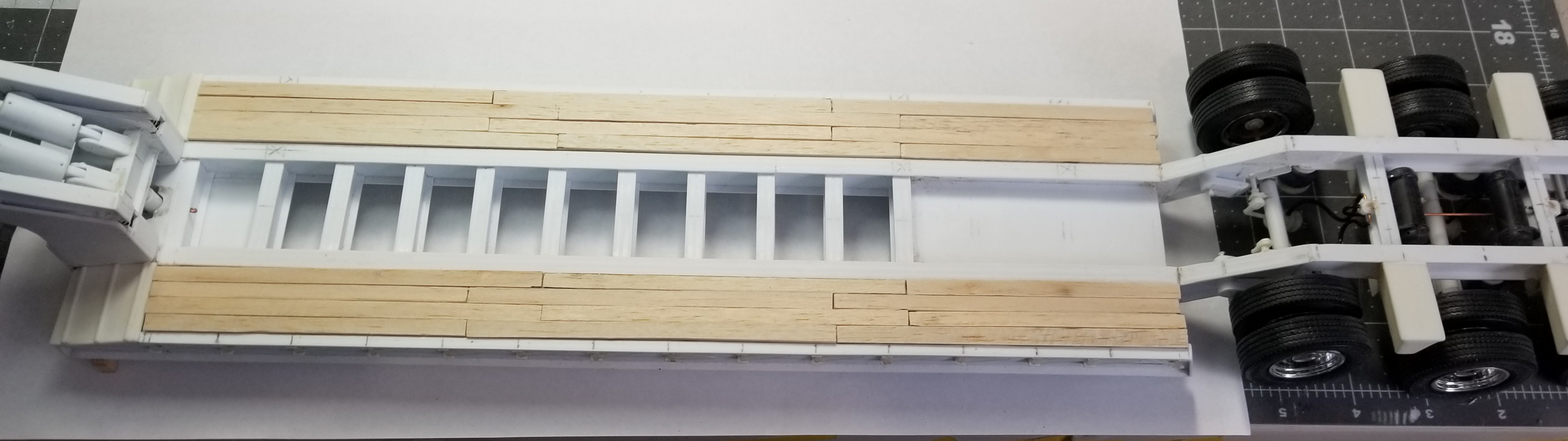
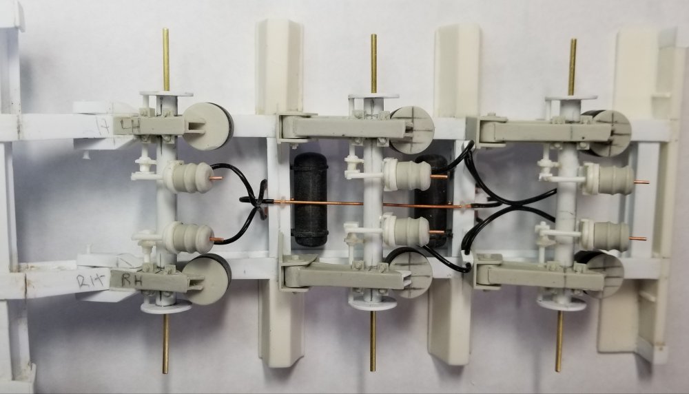
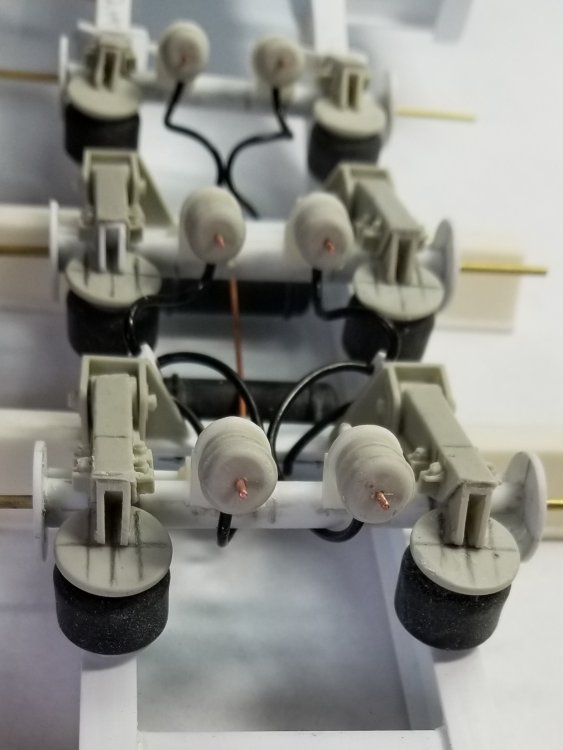
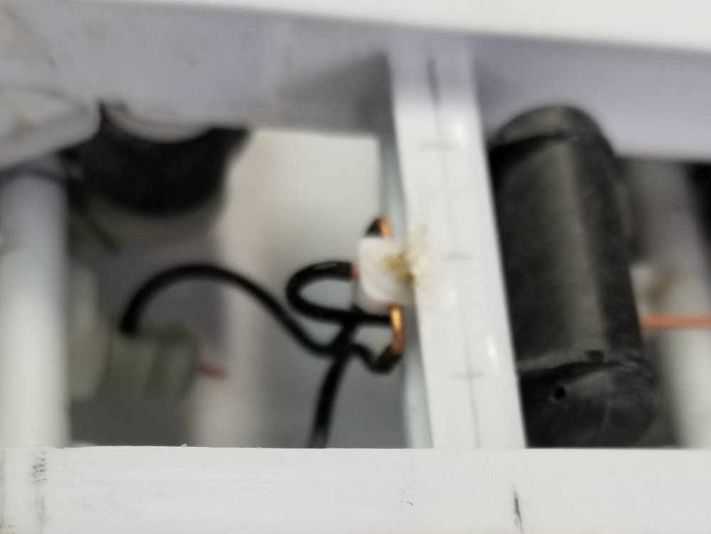
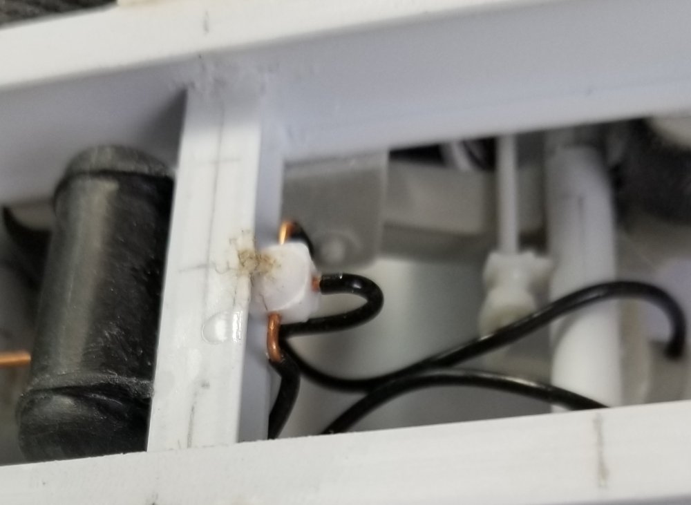
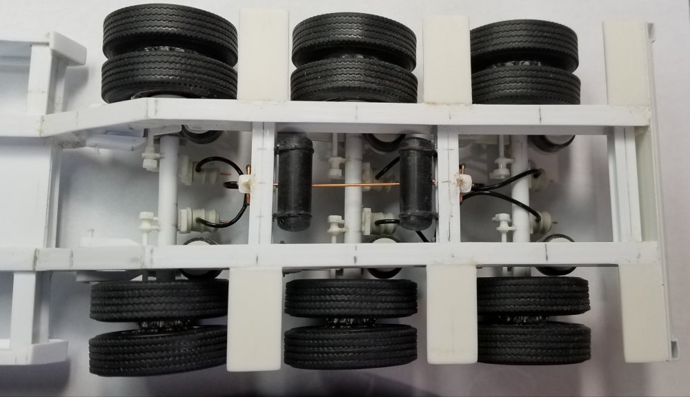
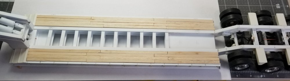
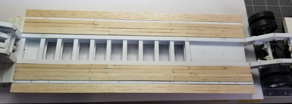
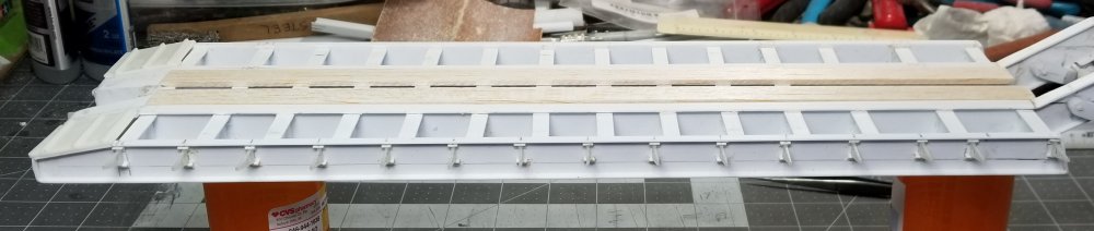
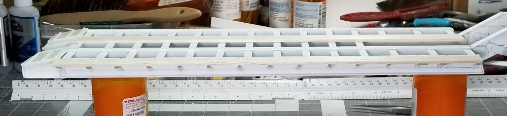
Hey Jeff I have the brakes fixed and plumbed. I also took some pictures of the trailer with the deck boards in place. view from the side. view of the bottom. You can see the "tee" fittings that I added to the rear axle pivot brackets in order to connect the center brakes and the rear brakes to the air control valve. view from the rear. This view shows how I added the Moluminum brake chambers to the ones I had on the axles already. front air valve. rear air valve. both air tanks and connection pipe. I still need to add the supply and control lines. View from the top with the tires added. this view shows the deck boards in place. this view shows the deck boards and the outrigger boards added. Well that's it for now be back with more updates soon. Ron G


-
WOW! that's going to be an ambitious project to tackle, but it sounds like fun. Lots of scratch building from the bits and bobs box, what...lol Ron G
-
Hey Harv...all the best buddy. Rember God will be looking out for you. Ron G
-
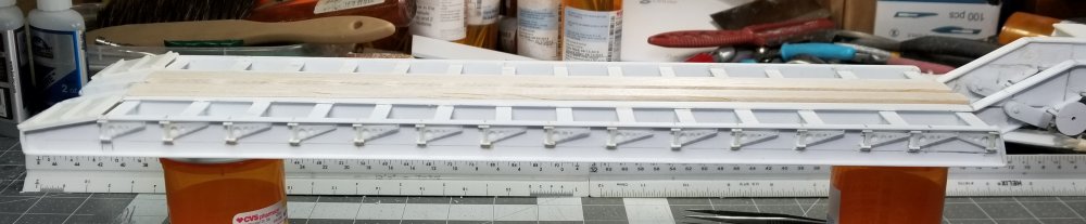
Hey all Today was a lot of small tedious work. I mounted one side of the outriggers to the trailer frame. Cut the two long outrigger boards and I have all the deck boards cut and sized, but didn't get any pictures of those. this view shows the outriggers folded in. this view shows them folded out. this view shows the outrigger board in place. I wish the outriggers were printed in the white detail plastic, because in the fine detail resin/plastic they are VERY!!!! brittle, and the whole weight of the excavator will be sitting on them. well that's it for now be back with more soon. Ron G
-
Got it, I have a fix, I still have the brake air chambers from the Moluminum set up, I can make them work. Ron G
-
Hey Jeff Spring brakes? Don't know what you mean can you post a picture or two? Thanks Ron G
-
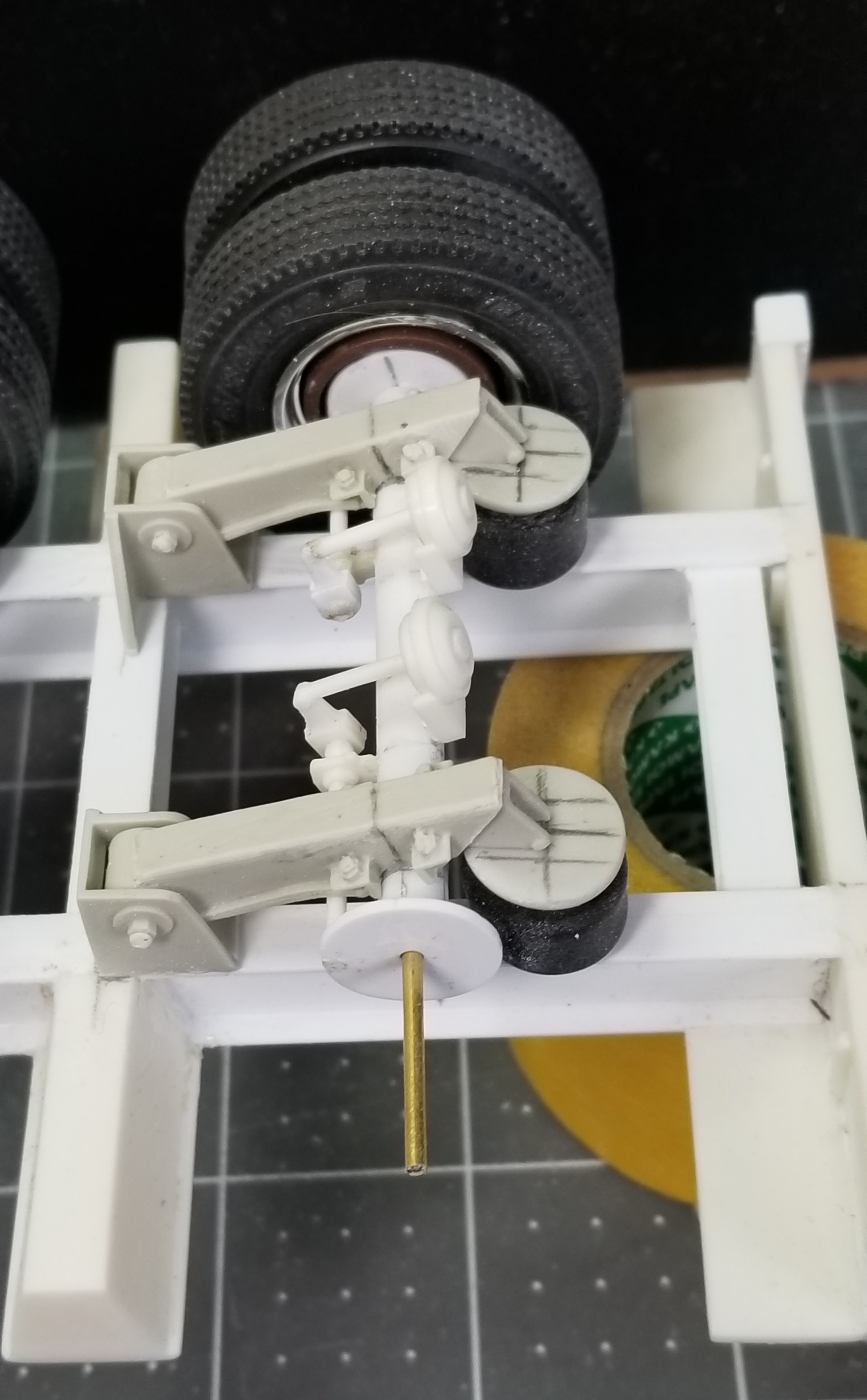
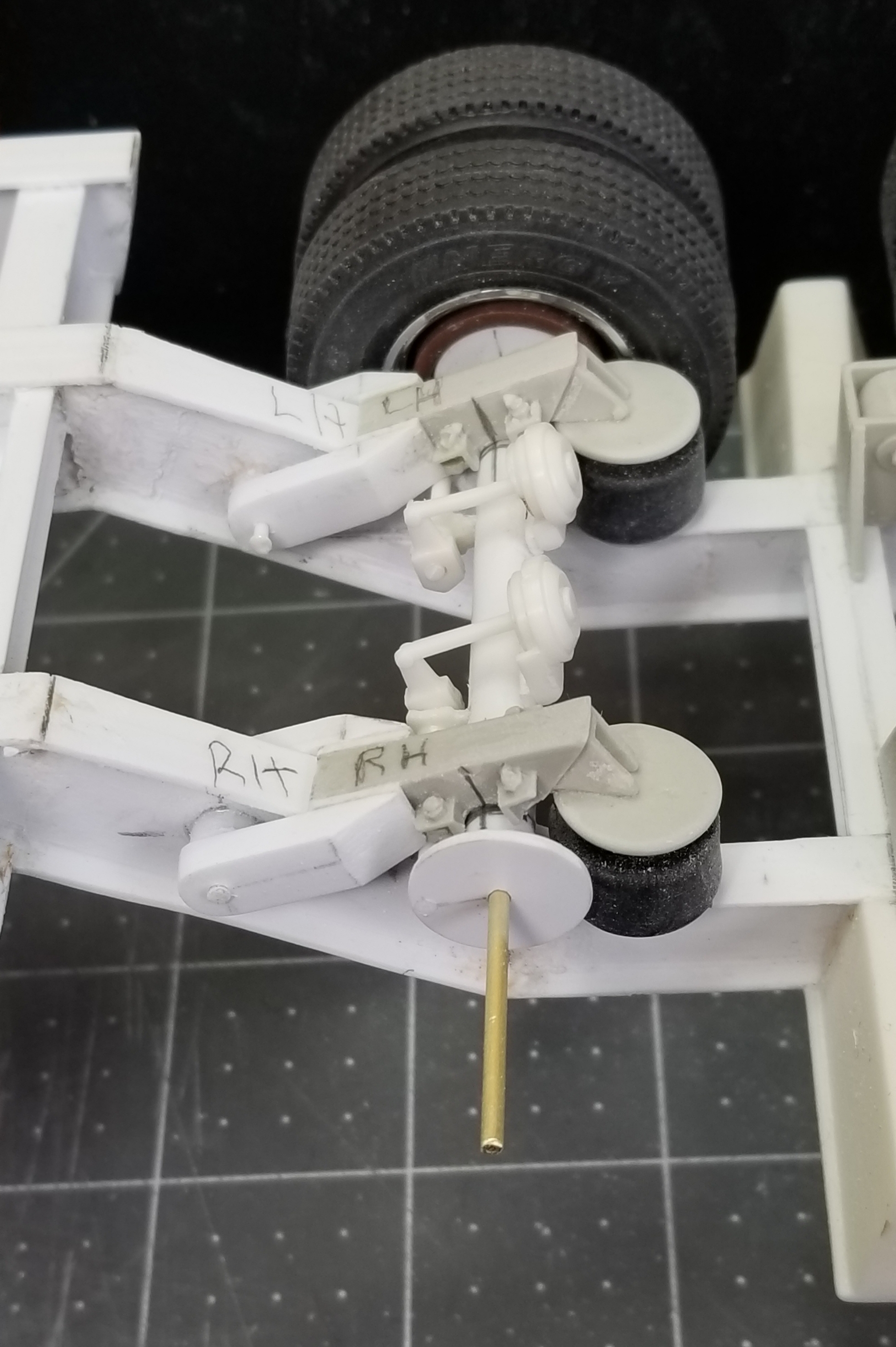
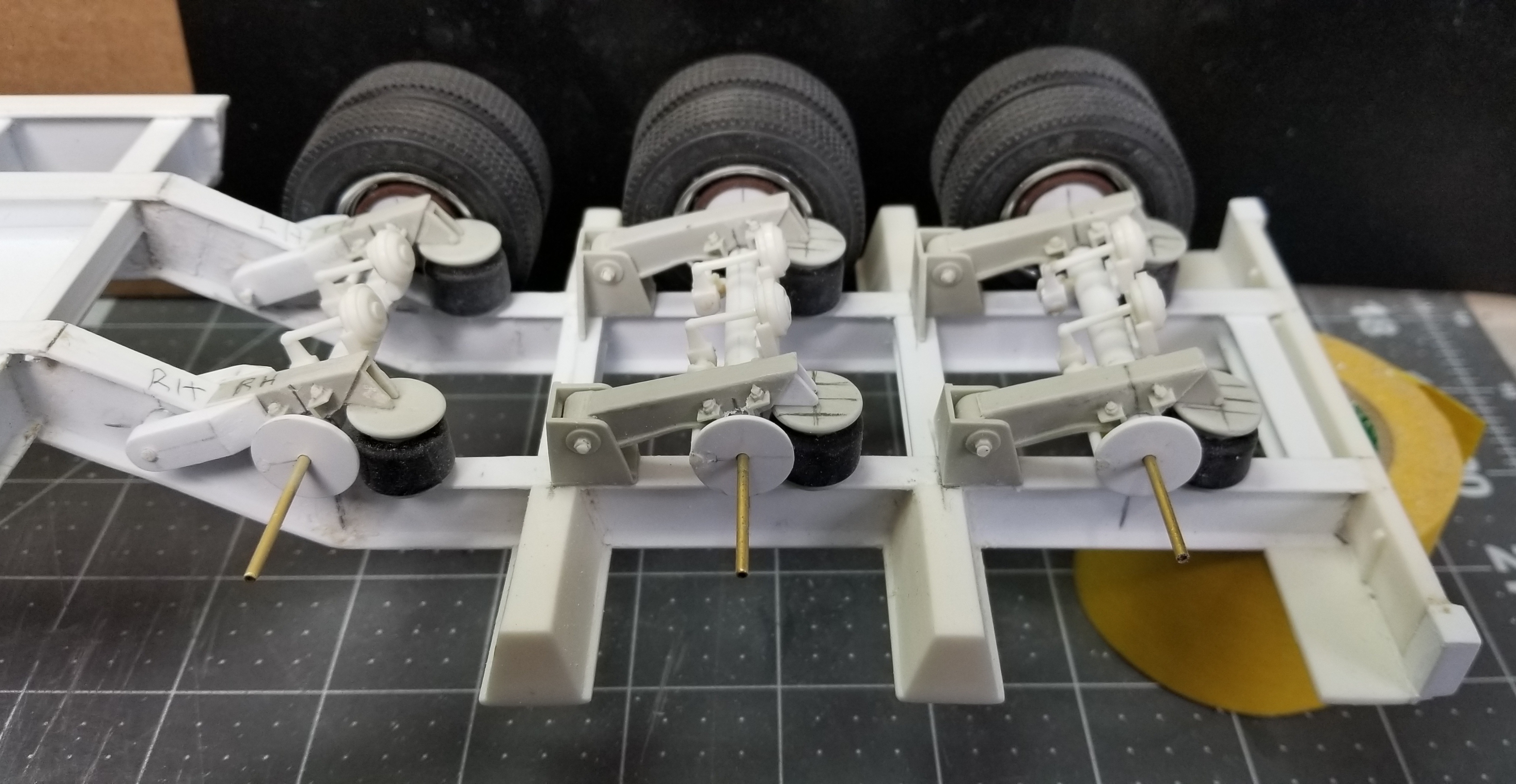
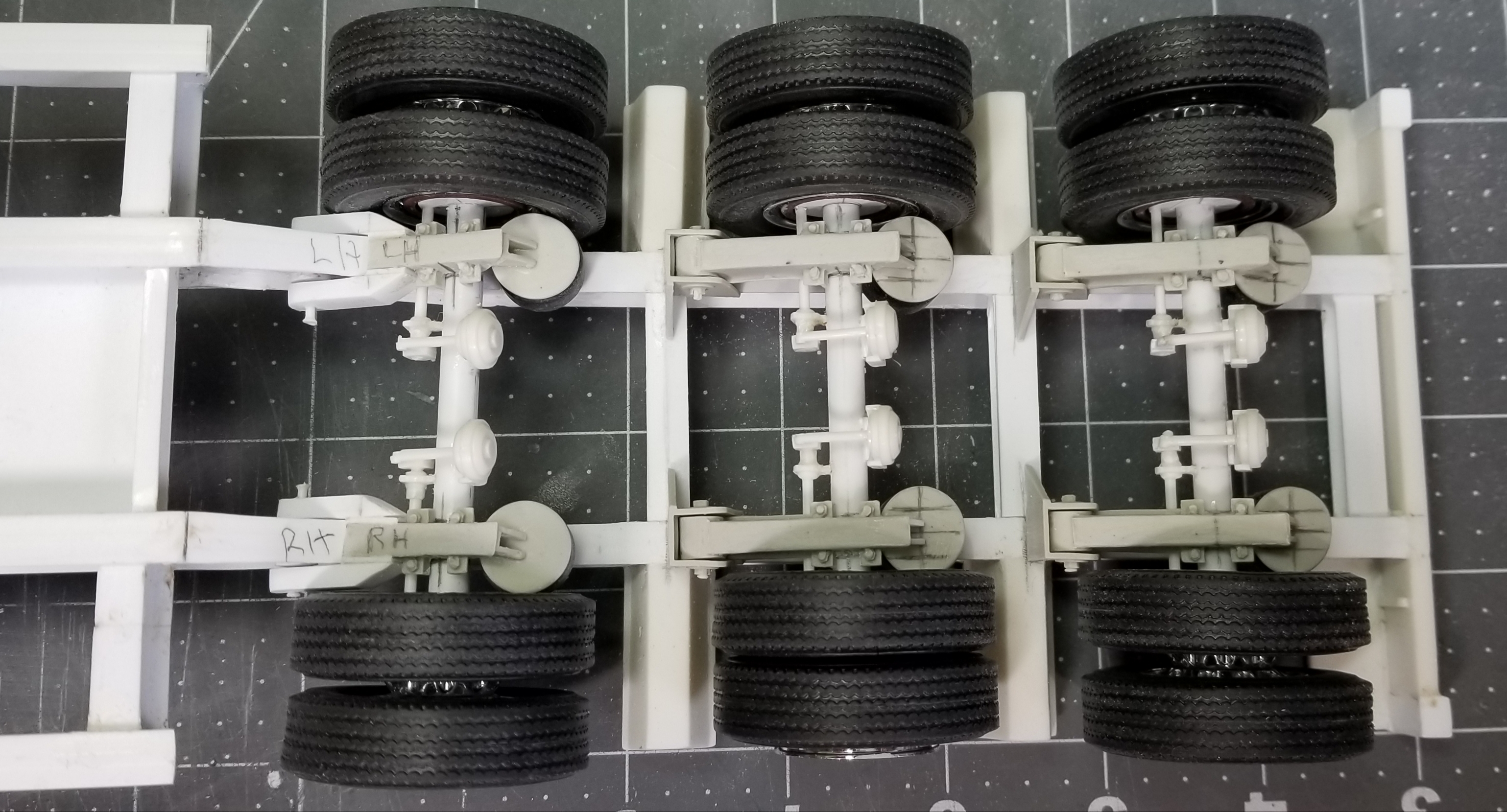
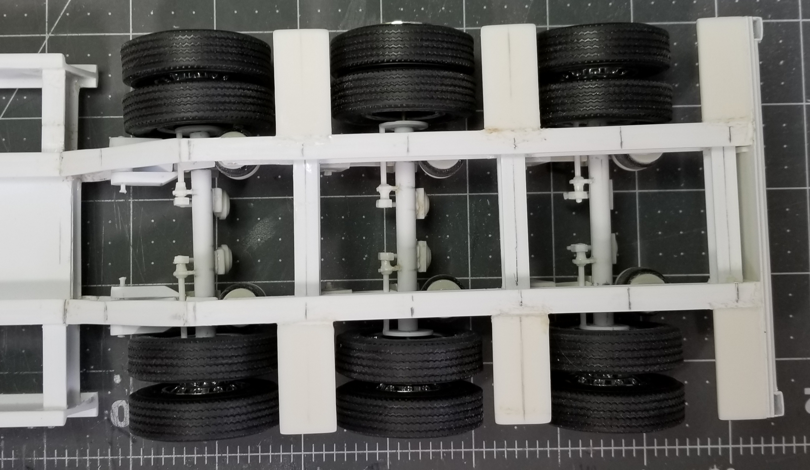
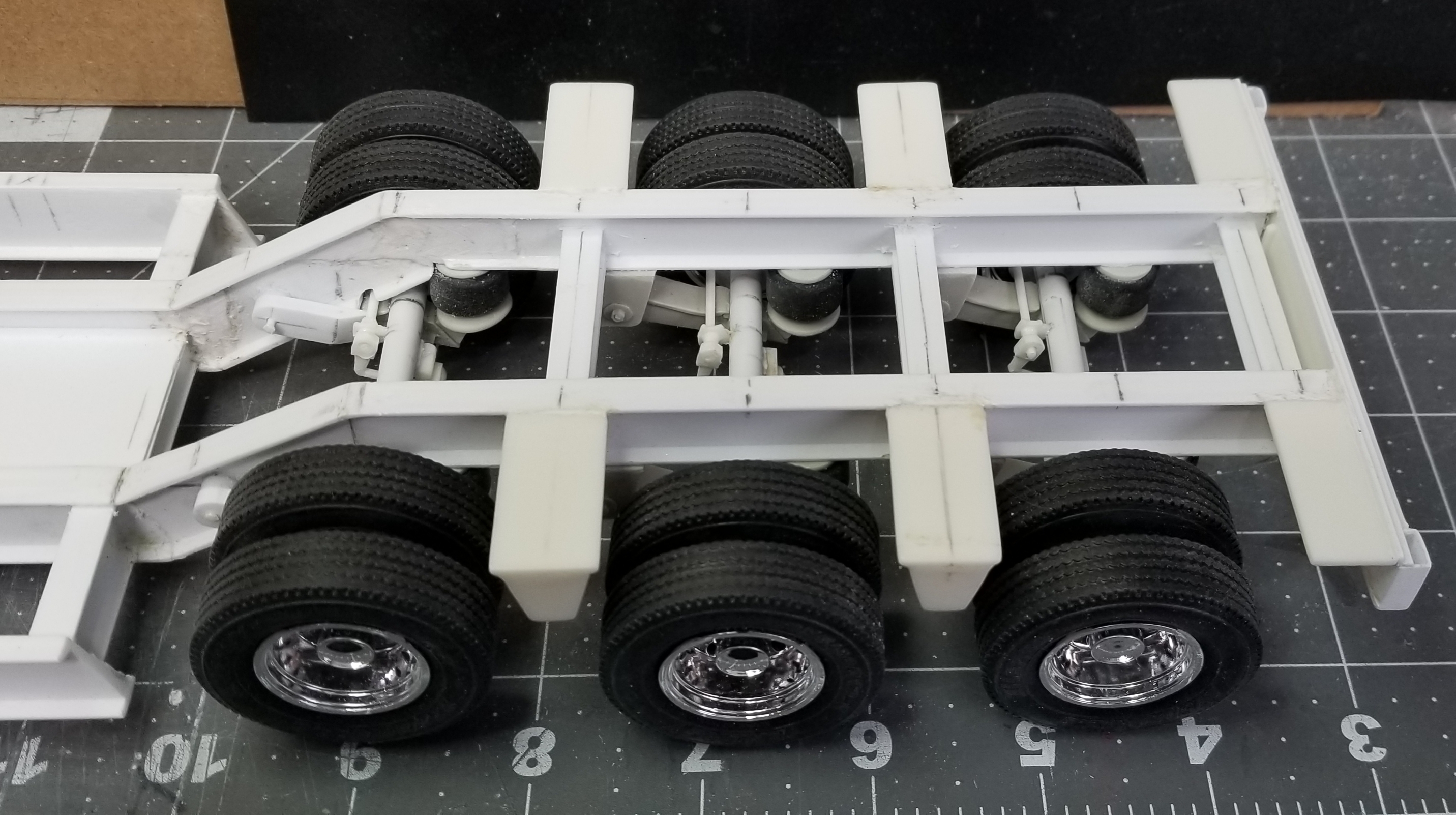
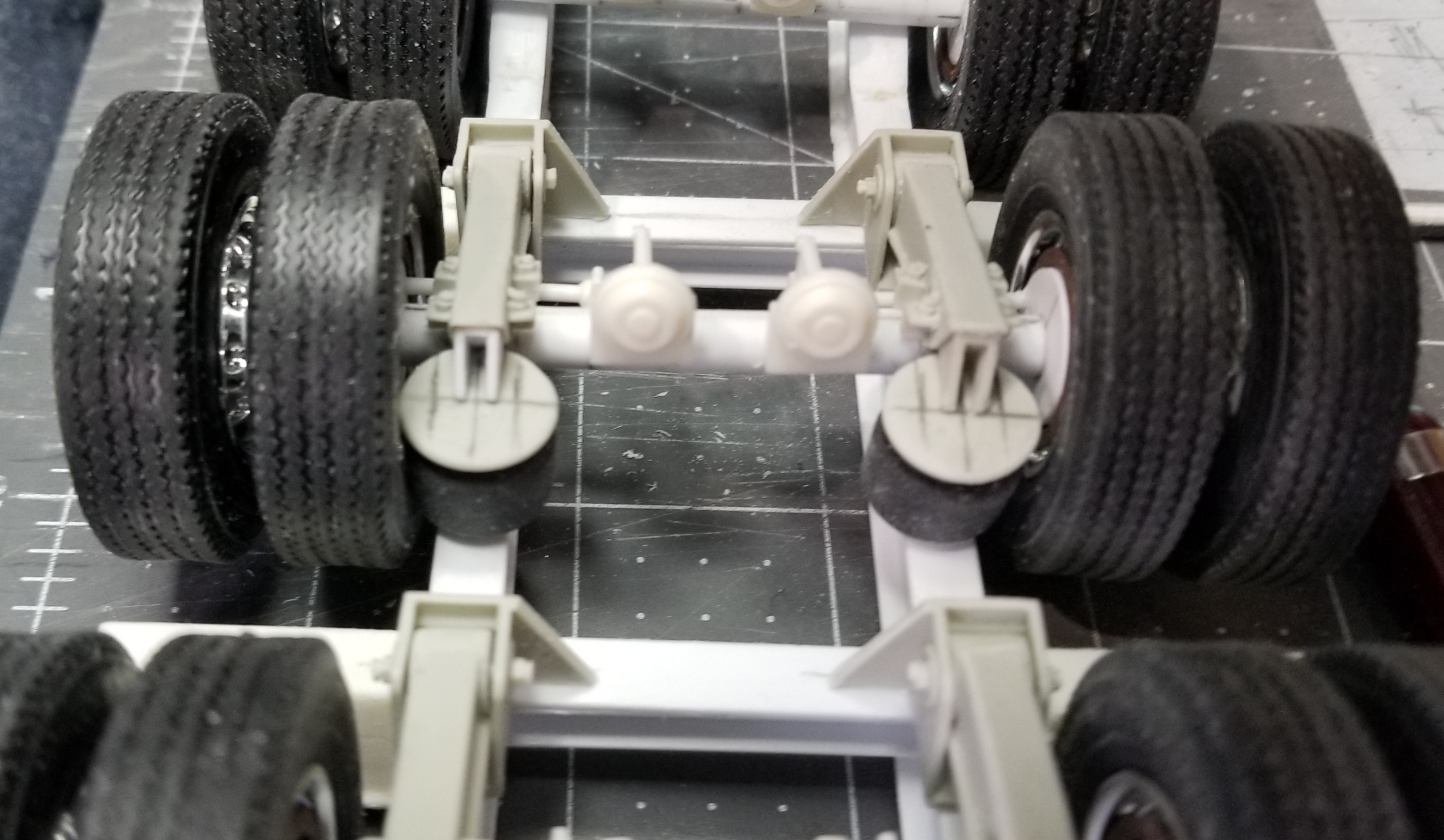
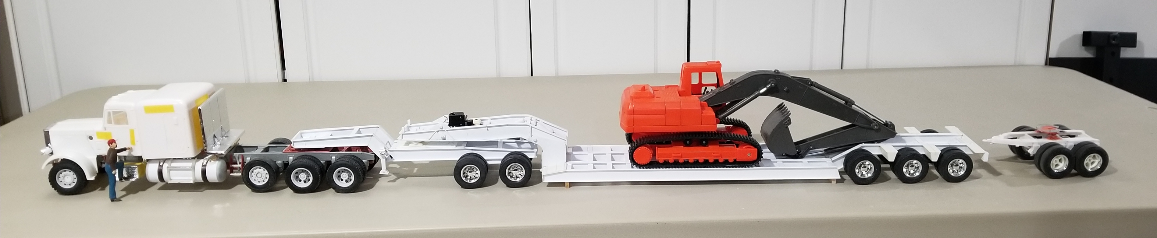
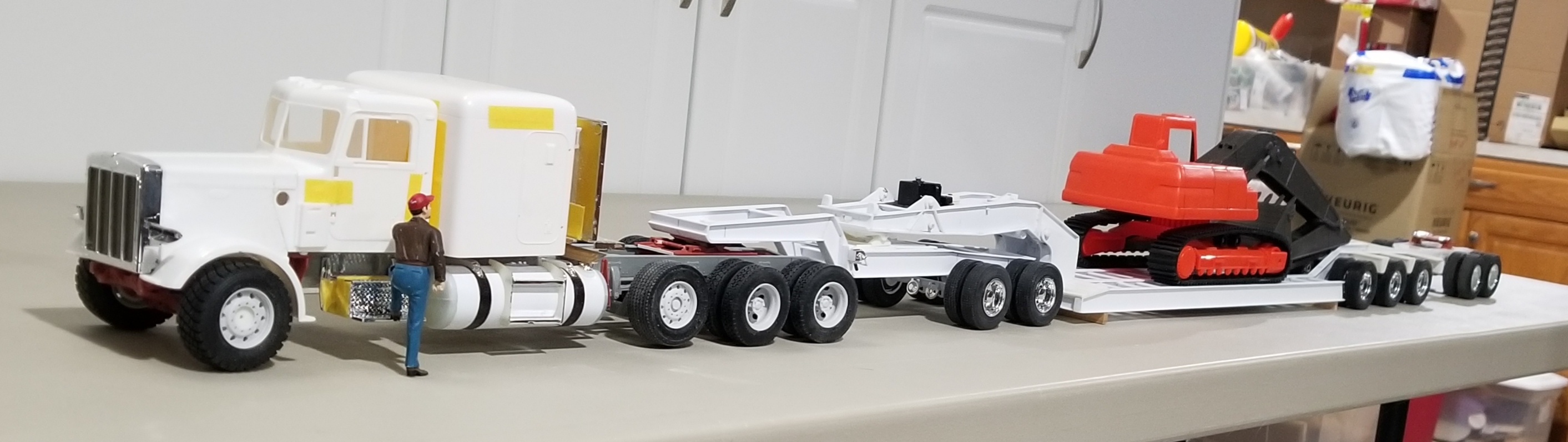
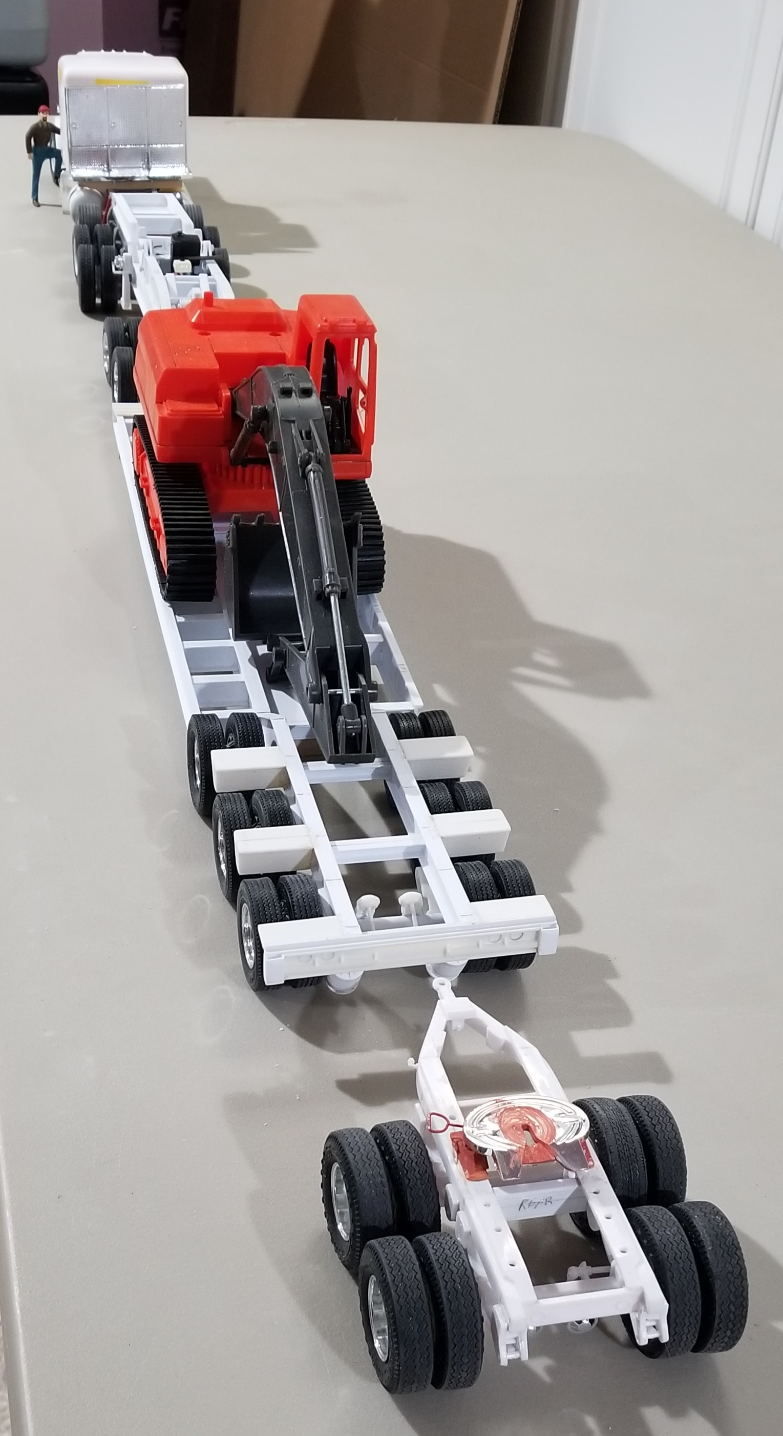
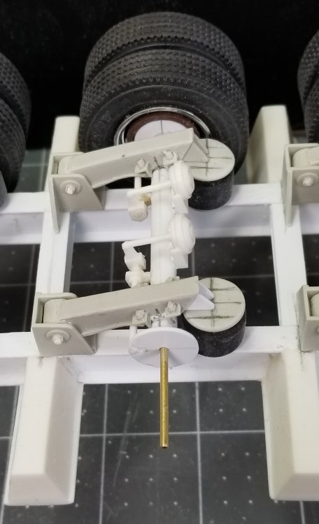
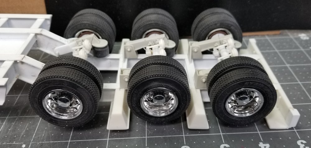
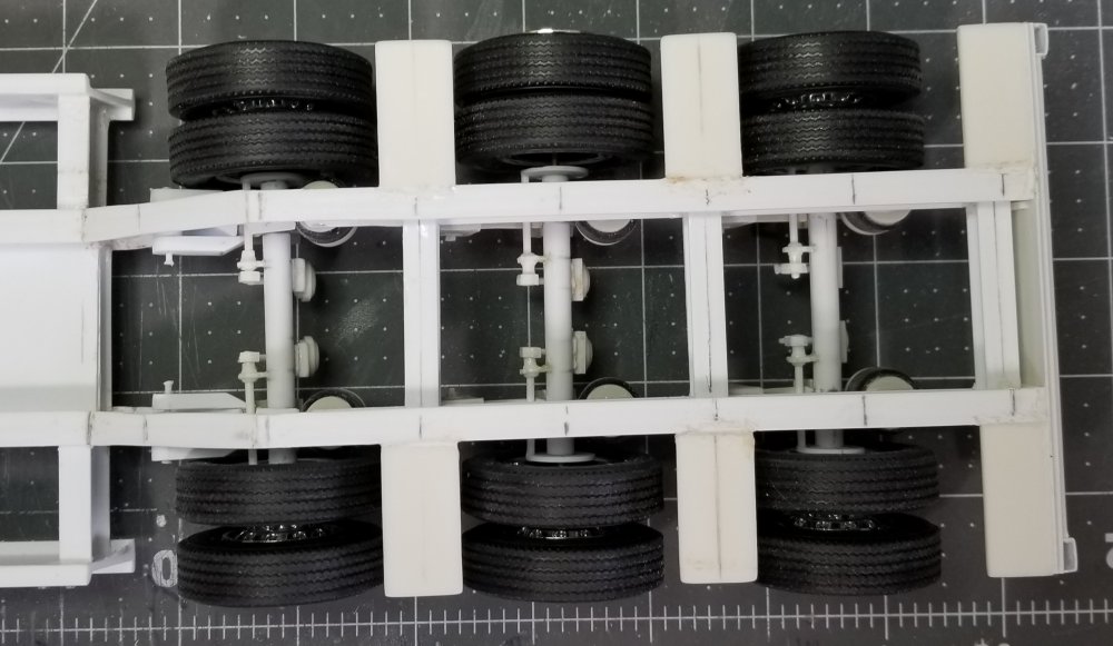
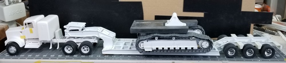
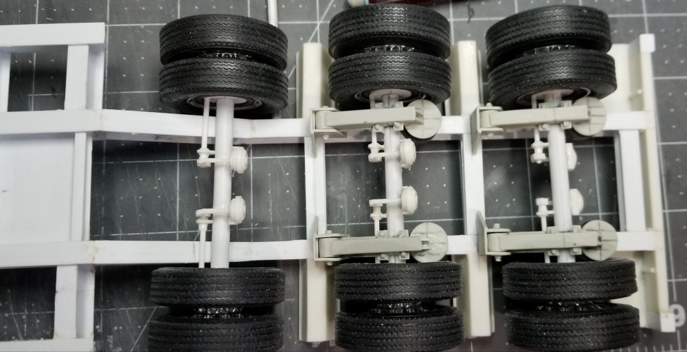
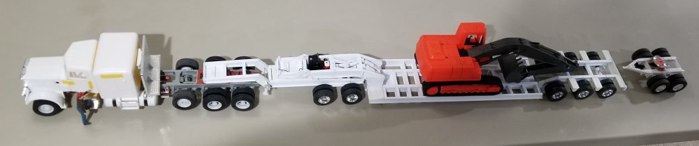
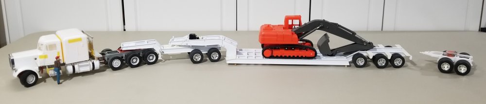
Hey guys I got the rear axle situation fixed and the front air suspension arms modified to fit around the trailer frame. this view shows the rear axle with the air brakes now on the correct side.duh! this view shows the center axle. this view shows the front axle and the modifications I had to make to the frame and the Moluminum parts so that they fit around the trailer frame. this view shows all of them. this view shows all of them with the wheels/tires added on. view of the bottom if the trailer rear. view from the top of the trailer rear. side view of the rear of the trailer. this view shows the trailer sitting on my Kenworth W925 and the Cat 374FL on it for perspective. I ordered some more Moluminum air suspensions for the jeep and the stinger/booster, so until I receive them in the mail there on hold. well that's it for now be back with more updates soon. Ron G


-
Peterpools is coming home!
CrankyCrafstman replied to Peterpools's topic in Site & Forum Announcements
Hey Peter it can be beaten, I'm proof, six years out from liver cancer. Ron G -
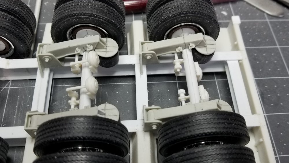
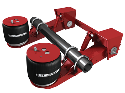
Hey guys Here's another update for you all. I received some 3D printed air suspensions from Shapways, but I guess I s#%*^ed up and got ones for a regular height trailer, not a lowboy. It would have been way to much work to rework them, so I went on line and looked around to see what I could find that might work. I went to Moluminums site and found just what I needed. this view shows the air suspension in place on the trailer. All that needs to be done now is add the shocks. another view of the air suspension from the rear. this view shows all the axles...WHOOPS!!!... I put the axle on the rear on upside down...#^*•☆... damn! Well tomorrow I'm going to have to fix it. This was not a good day, from the first part I dropped on the floor, to the second, to the third, etc., etc. to messing up the axle, so I decided to give up and go eat dinner. this view shows the real suspension that the model parts copy, Hendrickson 30ton. Well that's it for now be back soon. Ron G

-
Thanks guys I'm on my way down to the modeling bench as we speak, so look for an update soon. Ron G
-
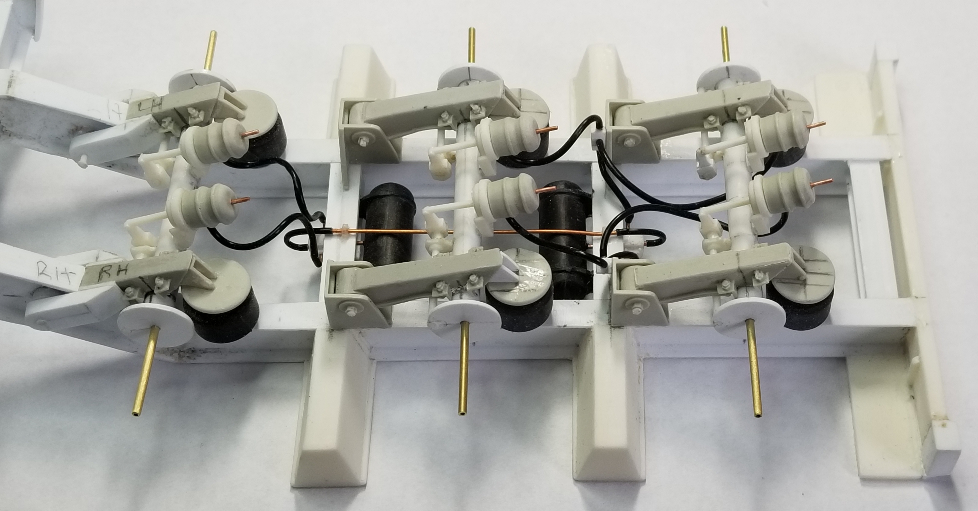
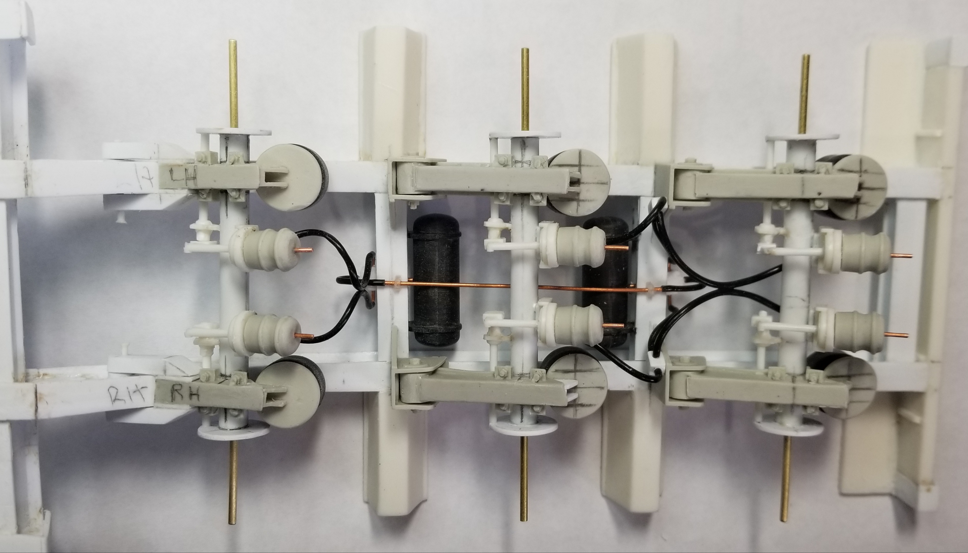
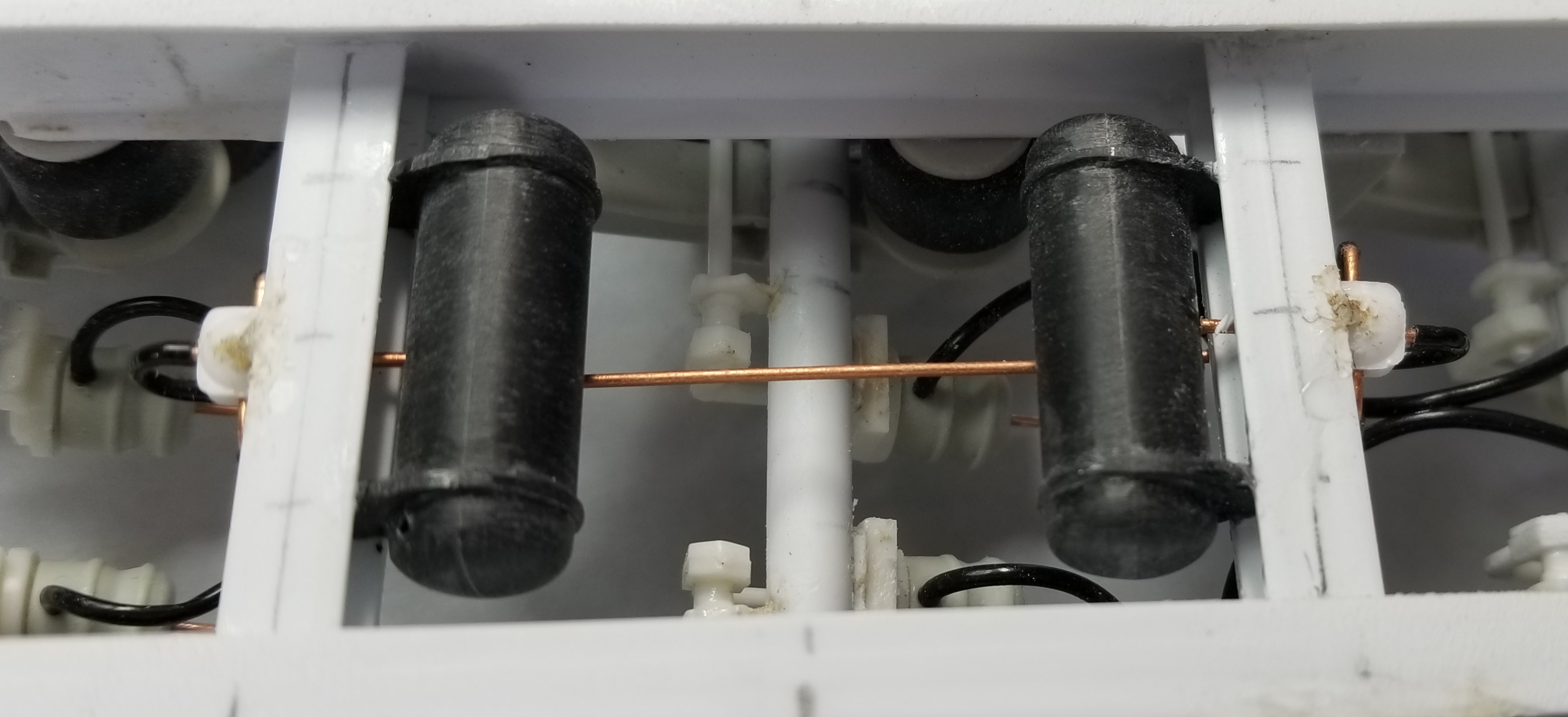
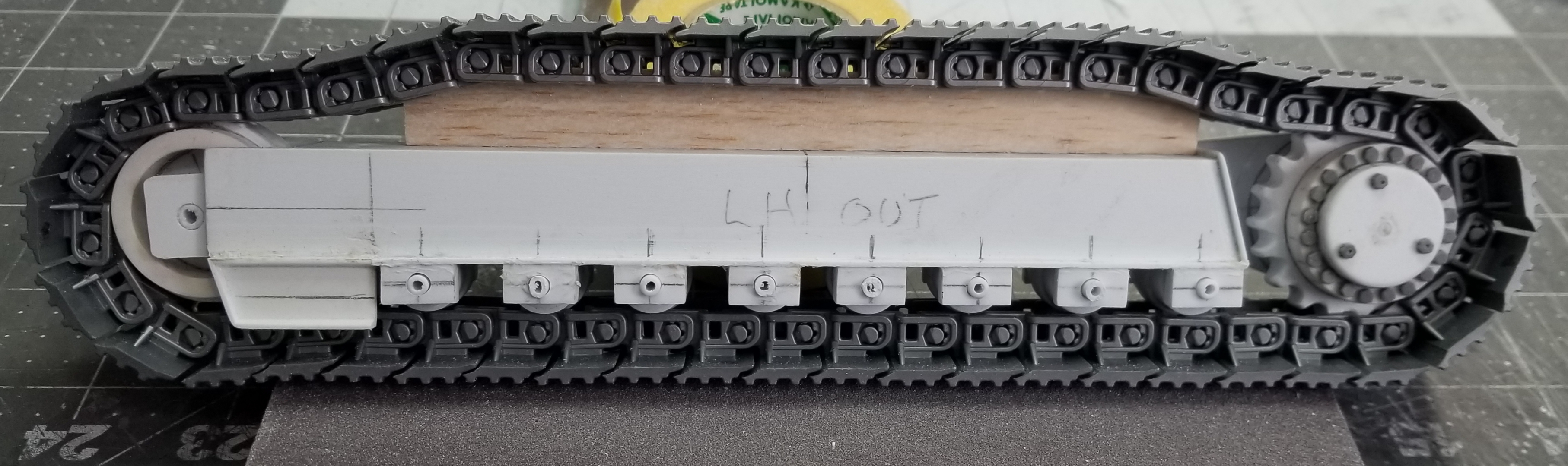
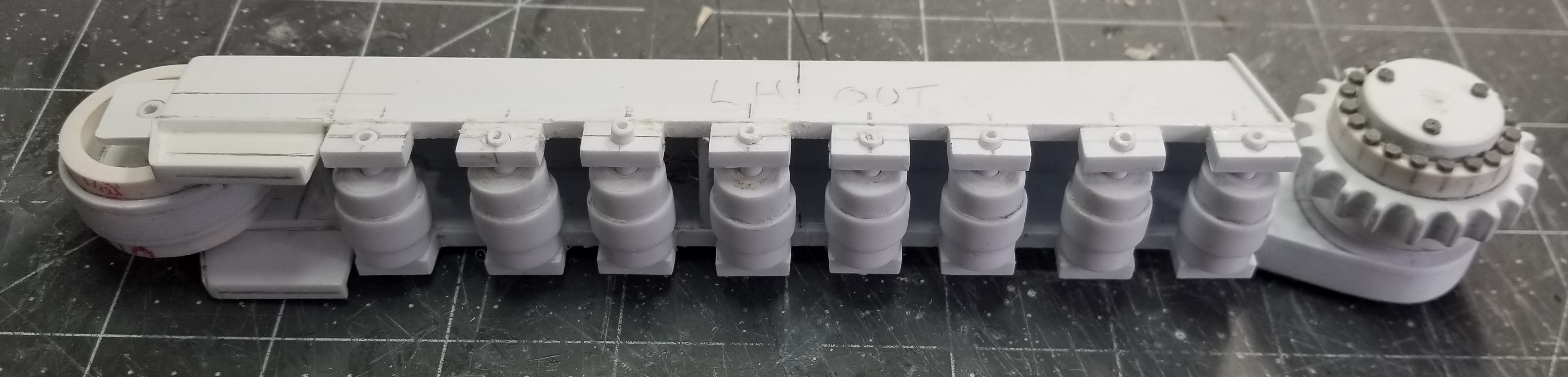
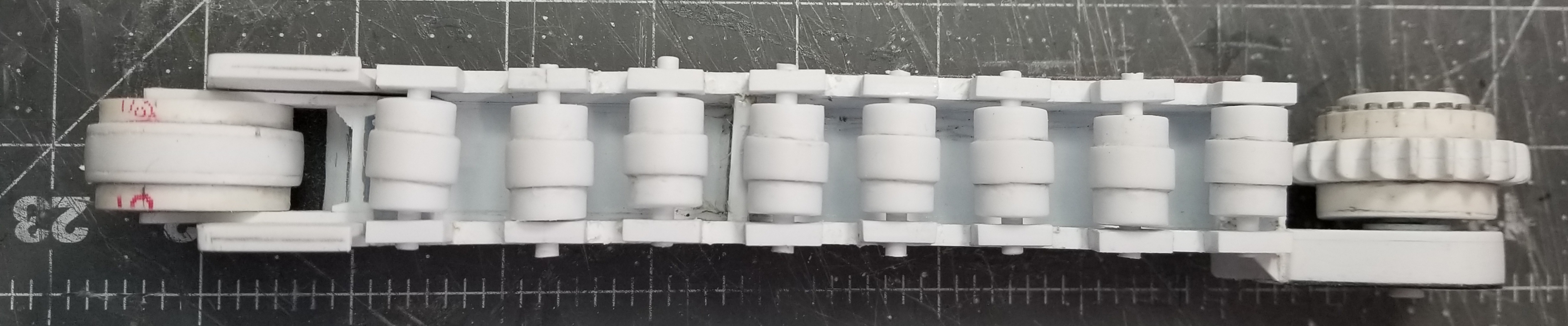
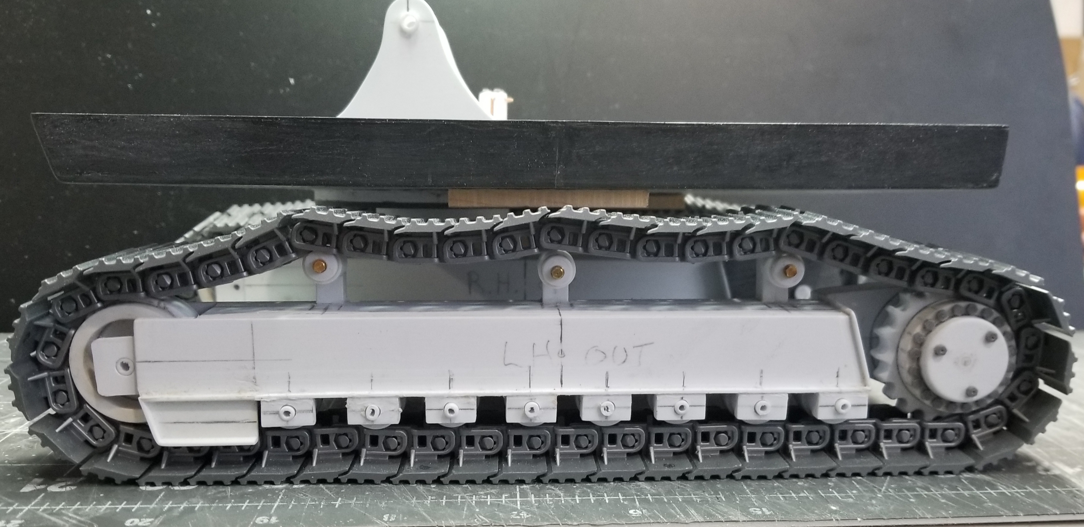
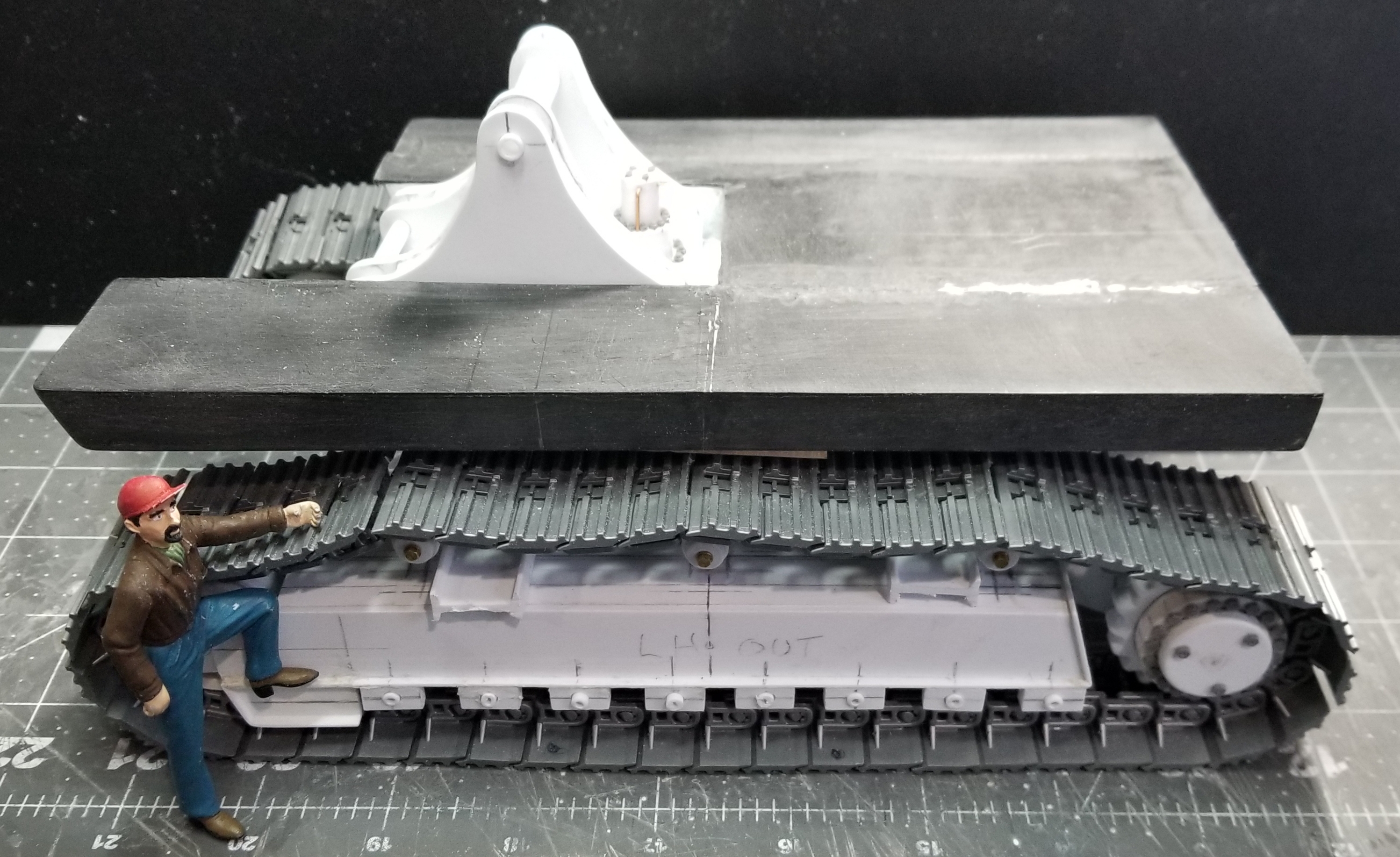
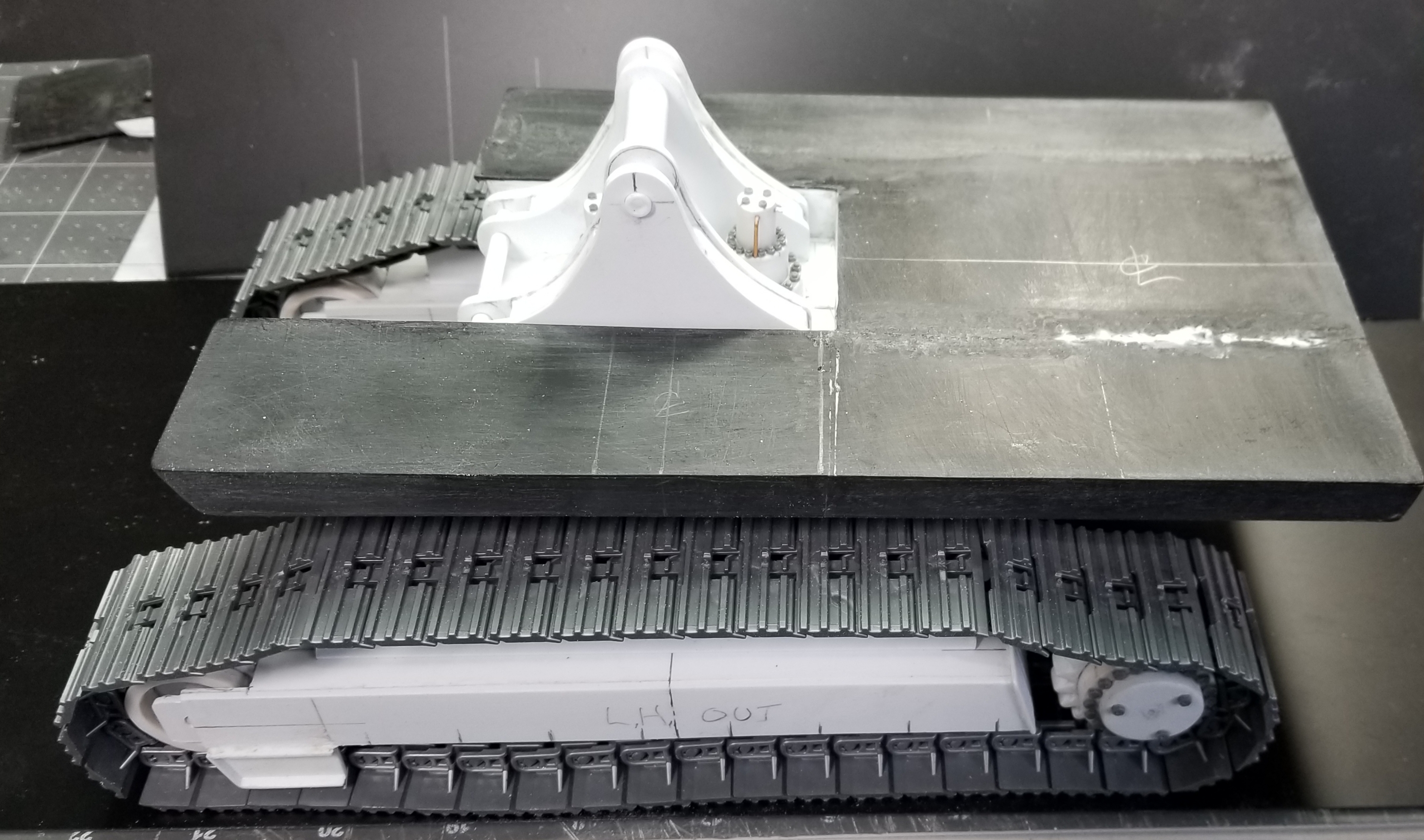
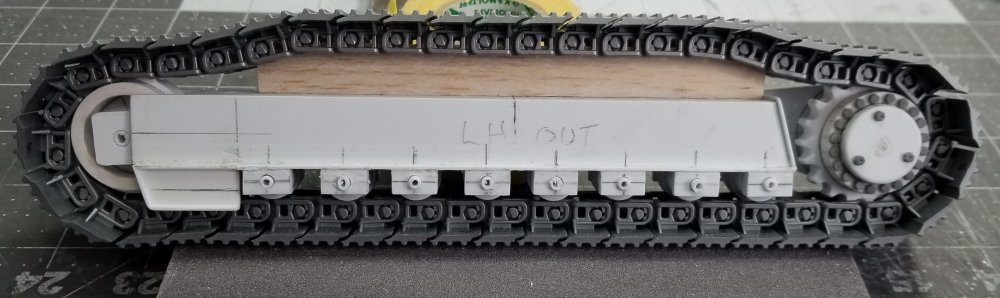
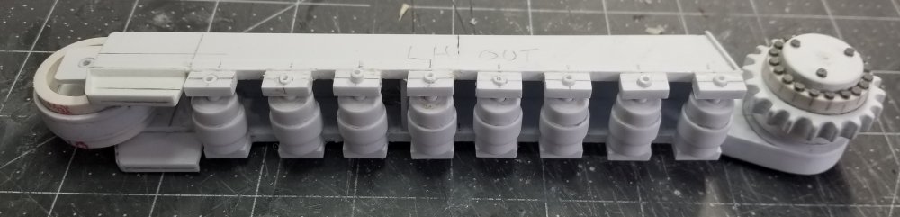
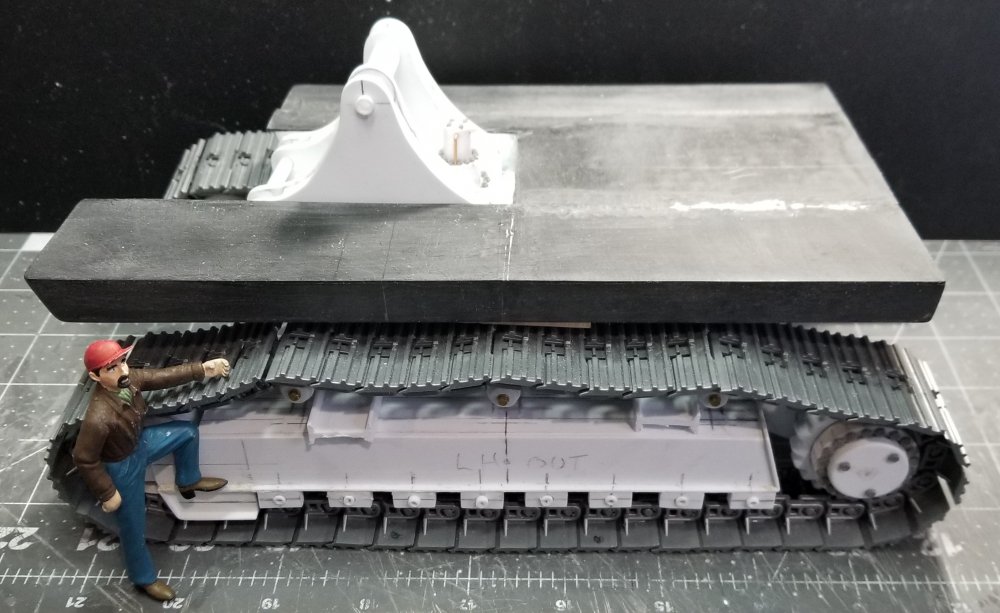
Hey guys Small update for you all. I have the lower rollers and the upper rollers done for the left hand side of the undercarriage frame. I took this photo early in the day before I added the upper rollers. this view shows the lower LH undercarriage frame after I added the rollers and mounting brackets. view from the bottom of the undercarriage frame. this view shows the upper rollers and their mounting brackets. this view shows the body base frame sitting on the undercarriage. I put my custom made figure in the picture for perspective. Well that's it for now be back with more updates soon. Ron G


-
☆☆☆ disregard☆☆☆
-
Hey Hubert Yeah I know, it's not finished yet, there are more reinforcements to add. Ron G
-
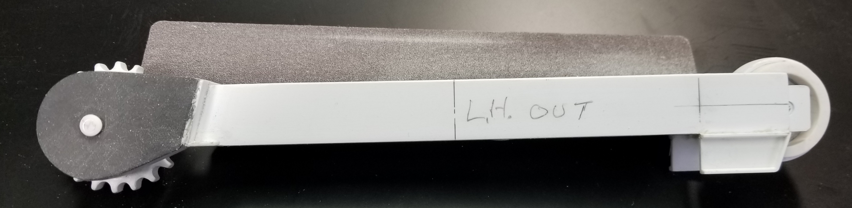
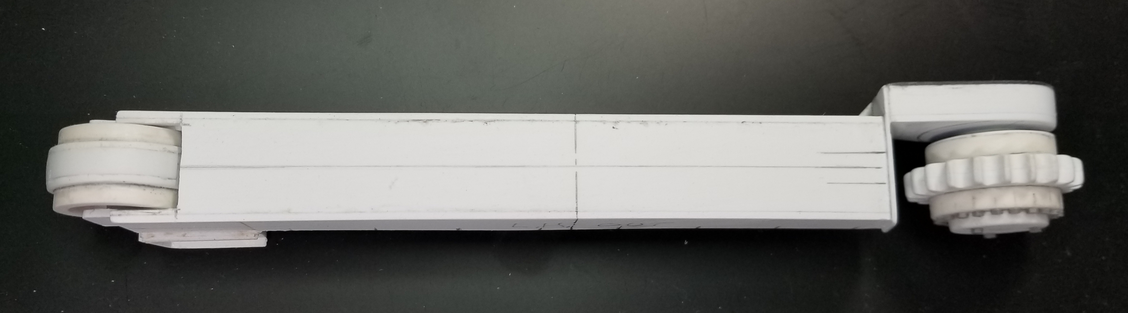
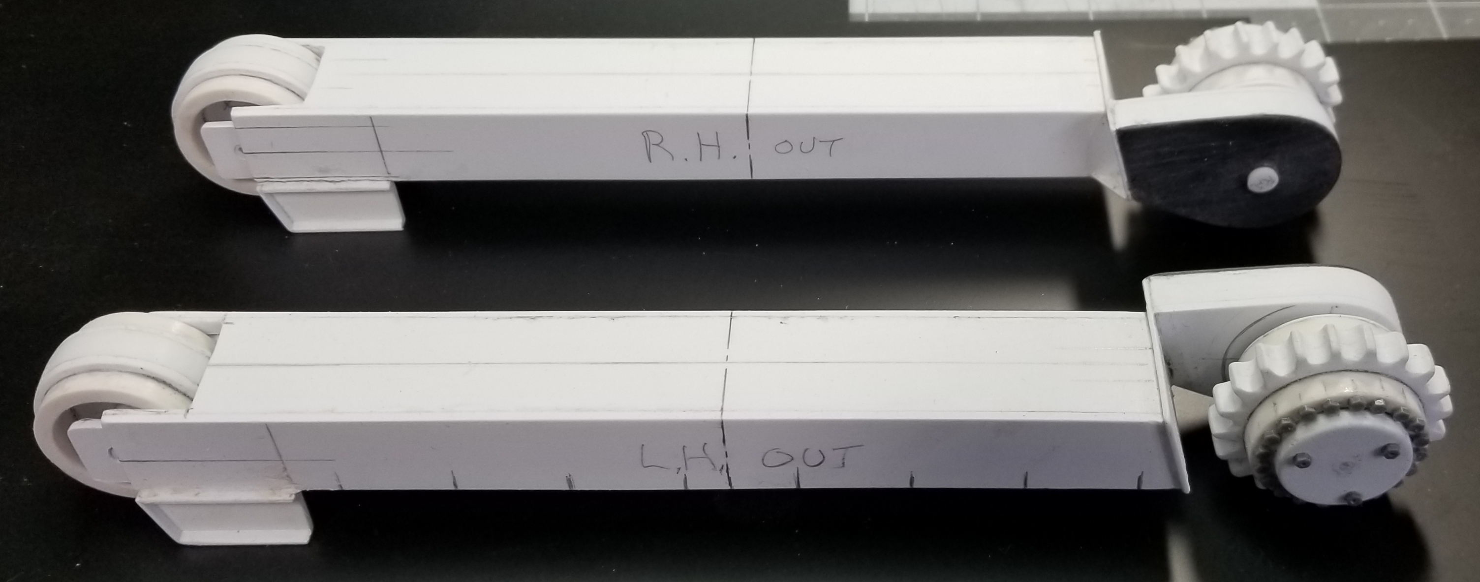
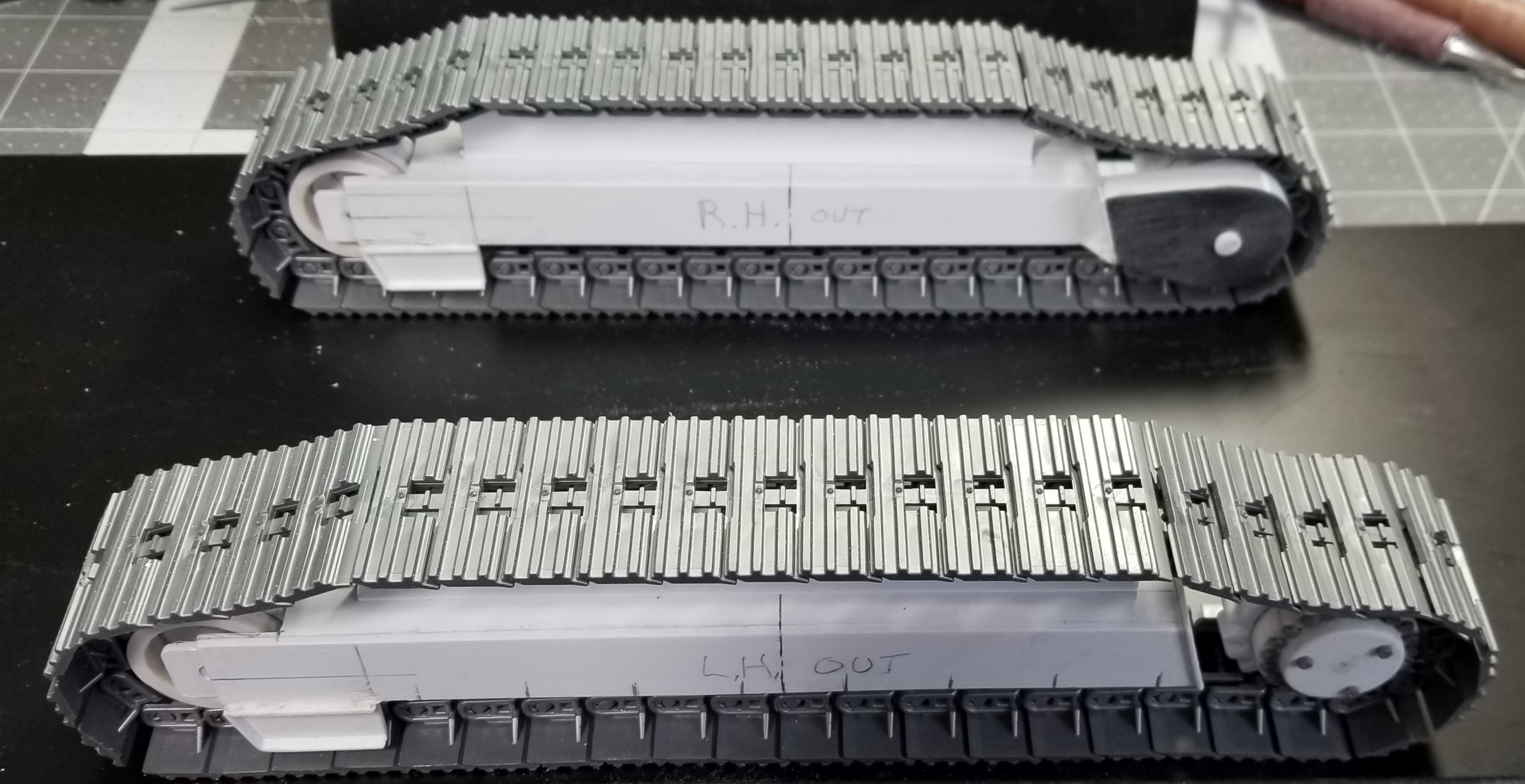
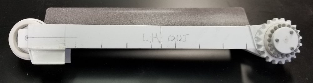
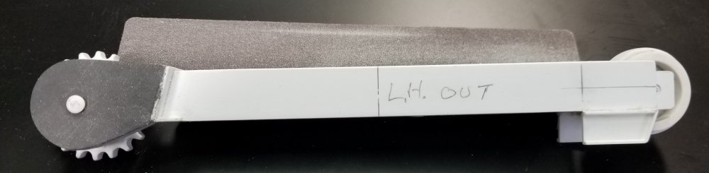
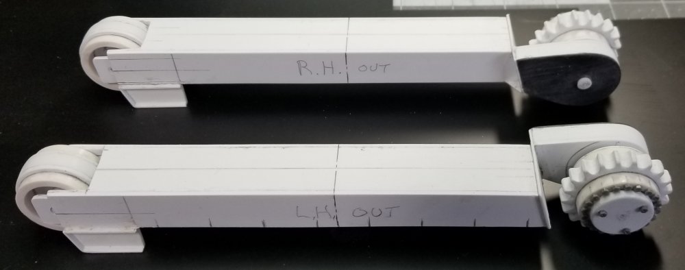
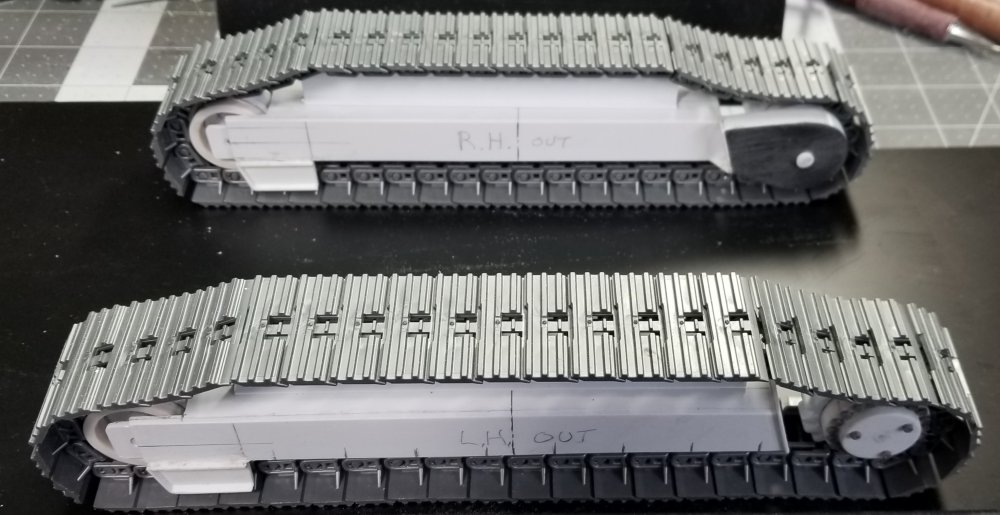
Hey guys I now have the two side frames about half way done. this view shows the LH side frame from the outside. this view shows the LH side frame from the inside. top view of the LH side frame. this view shows both the LH & RH side frames. this view shows them with the tracks added. this view shows them with the base frame in place. I still have to make the 3 upper rollers and the 8 lower rollers and there mounting brackets for both sides, plus the 2 steps on each side frame, both sides and the main center section that attaches to the 2 side frames and the main base frame together, plus all the bolt heads...! well that's it for now be back soon with more updates. Ron G


-
☆☆☆☆ disregard this☆☆☆☆
-
Hey guys Just some more pictures that I didn't post before.


-
oouucchh!!!
-
Thanks guys I have both of the idlers and the drive sprockets done now. Time to start on the undercarriage frame. Ron G