


Landlubber Mike
-
Posts
1,275 -
Joined
-
Last visited
Content Type
Profiles
Forums
Events
Gallery
Posts posted by Landlubber Mike
-
-
That's going to be quite the project with all that aftermarket. Looking forward to it!
-
 1
1
-
-
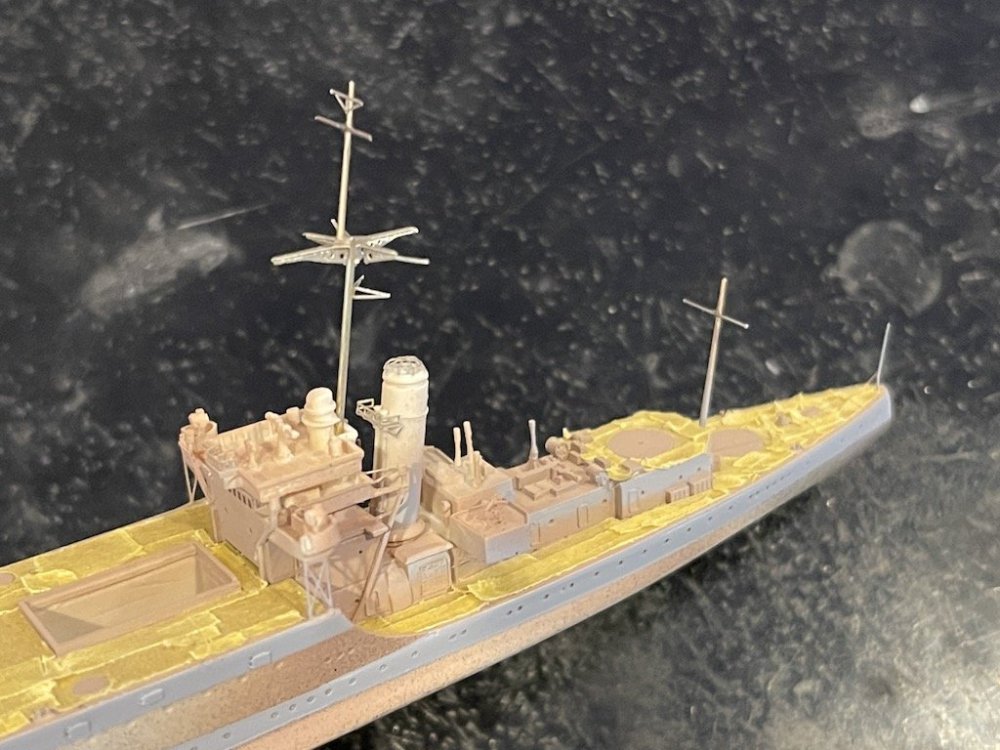
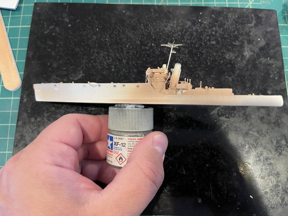
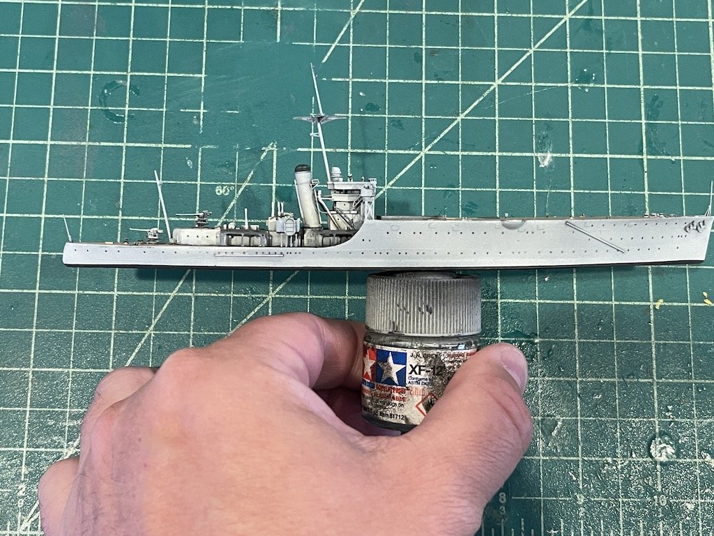
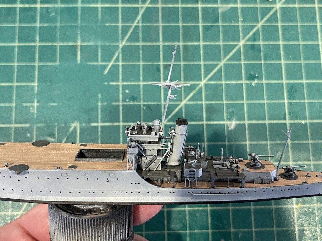
Primed, painted, and now adding in the remaining details before weathering and rigging. I've been very pleased with the details on the PE and resin parts for this kit. Niko did a really great job with this kit.

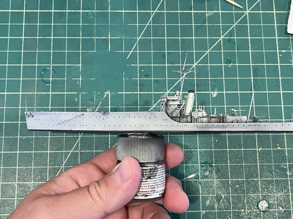
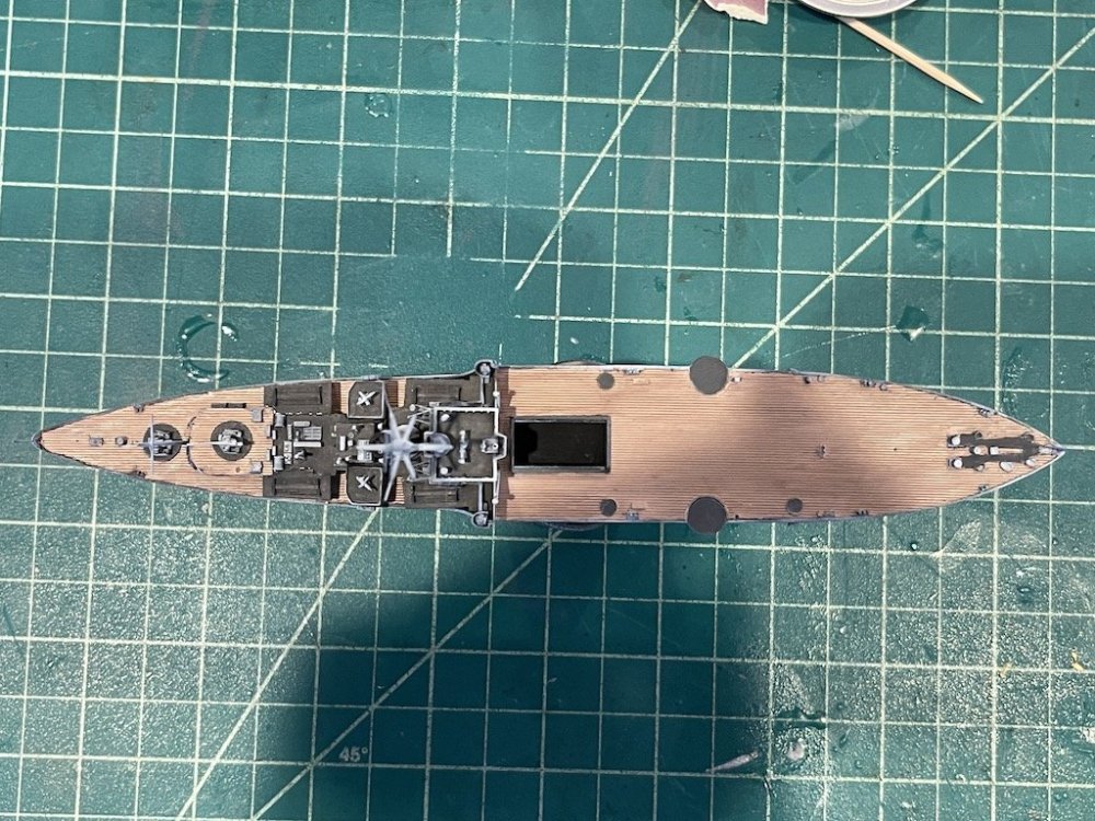

Thanks for looking in!
-
8
-
-
Looking great Rob. Nice smooth base there. Cool looking canopy on this subject.
-
2
-
 1
1
-
-
Wow, that came out really great Bill!! Nice job!
-
3
-
-
I'm in the DC area, and it smells like an active campfire and the sky is really hazy. I was outside for about 45 min this morning walking the dog and taking my kids to the bus stop, and now I'm definitely feeling it. Be safe everyone!
-
3
-
-
Wow!! Super cool display and model Gary! Really cool!
-
1
-
-
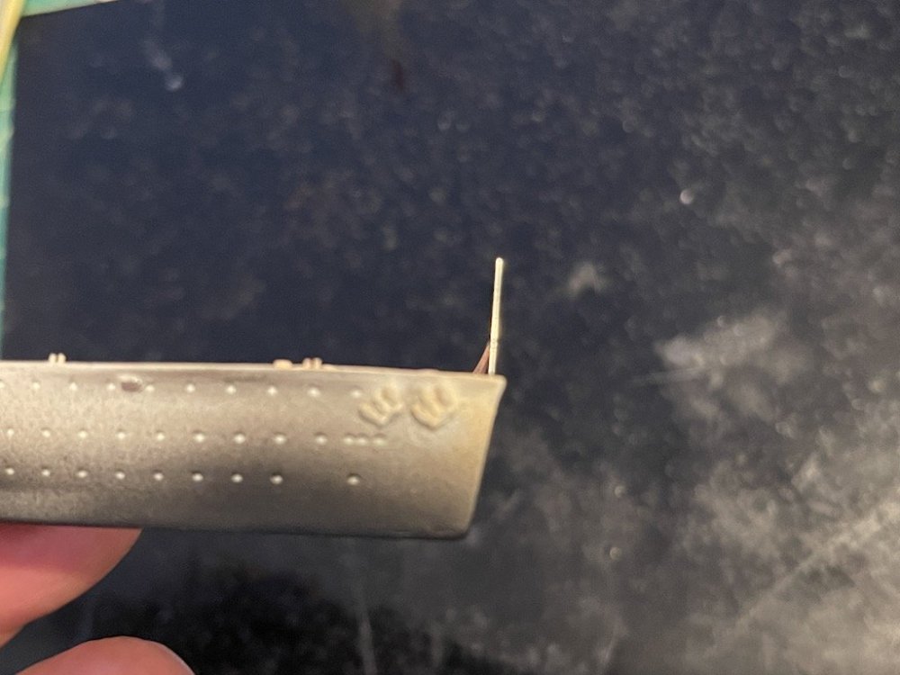
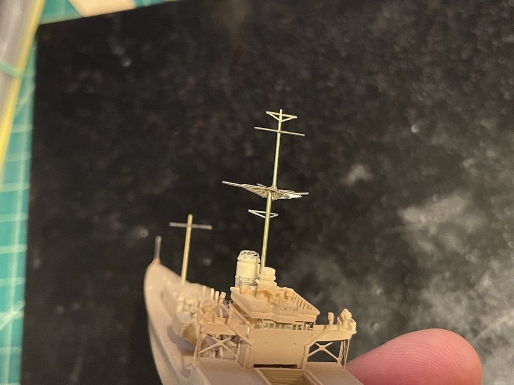
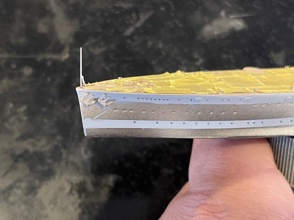
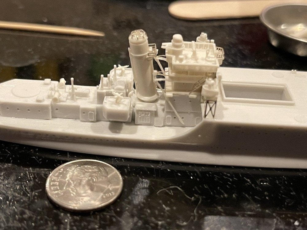
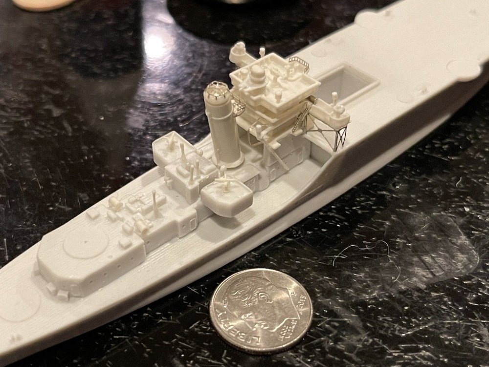
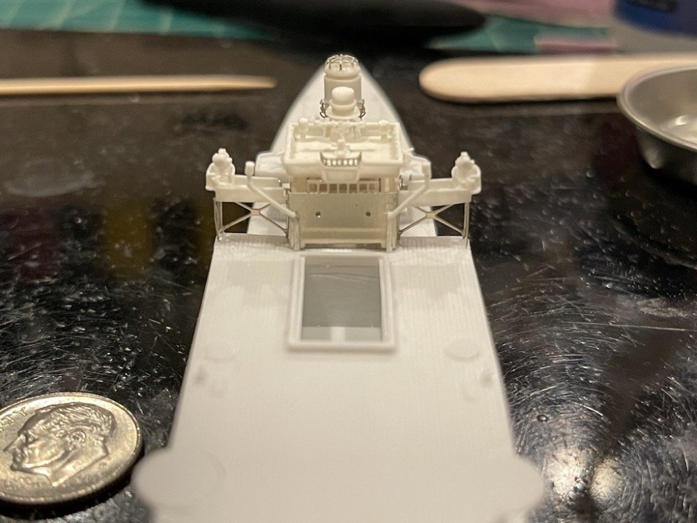
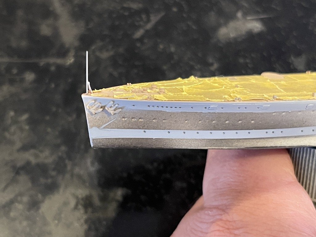
I've made some good progress on the Albatross. Added the bow and stern posts, and finished building the masts. I use cut down insect pins - which I think are stainless steel - for things like the posts that need a little more structural integrity and won't bend like brass or other materials when I invariably end up bumping into them.
After taping the wooden decks - which was a project in itself - I ended up trying to replicate the plating runs on the hull by taping off alternating rows, and then spraying a heavy coat of Mr. Surfacer 1200. We'll see how it goes - it's tricky in that you don't want to go overboard with too thick of paint as it will look out of scale.
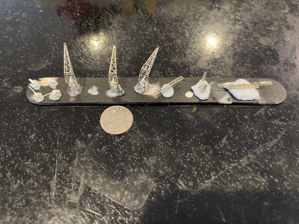
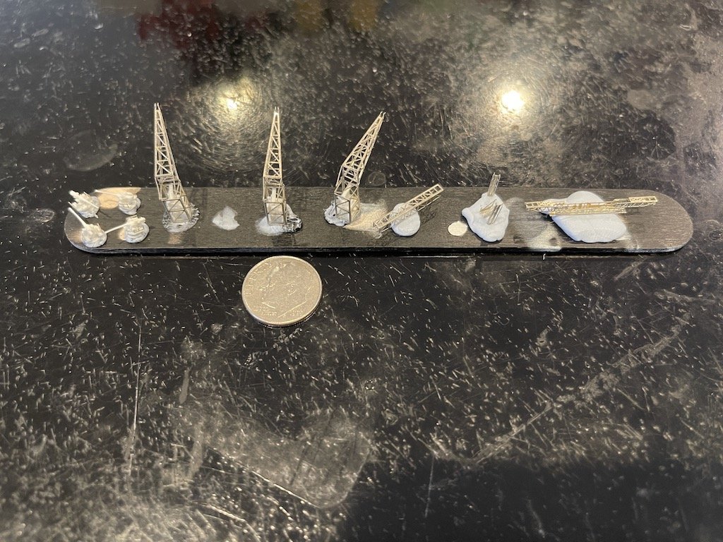
I also managed to finish the cranes by adding aftermarket hooks from Rainbow and put together the catapult:
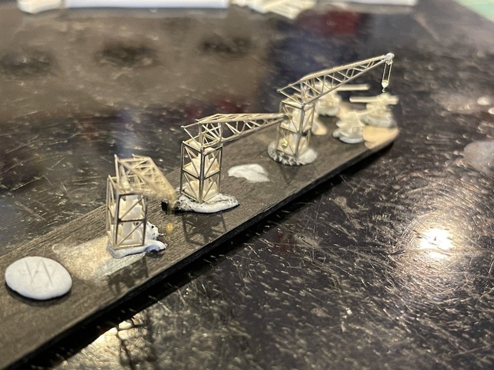
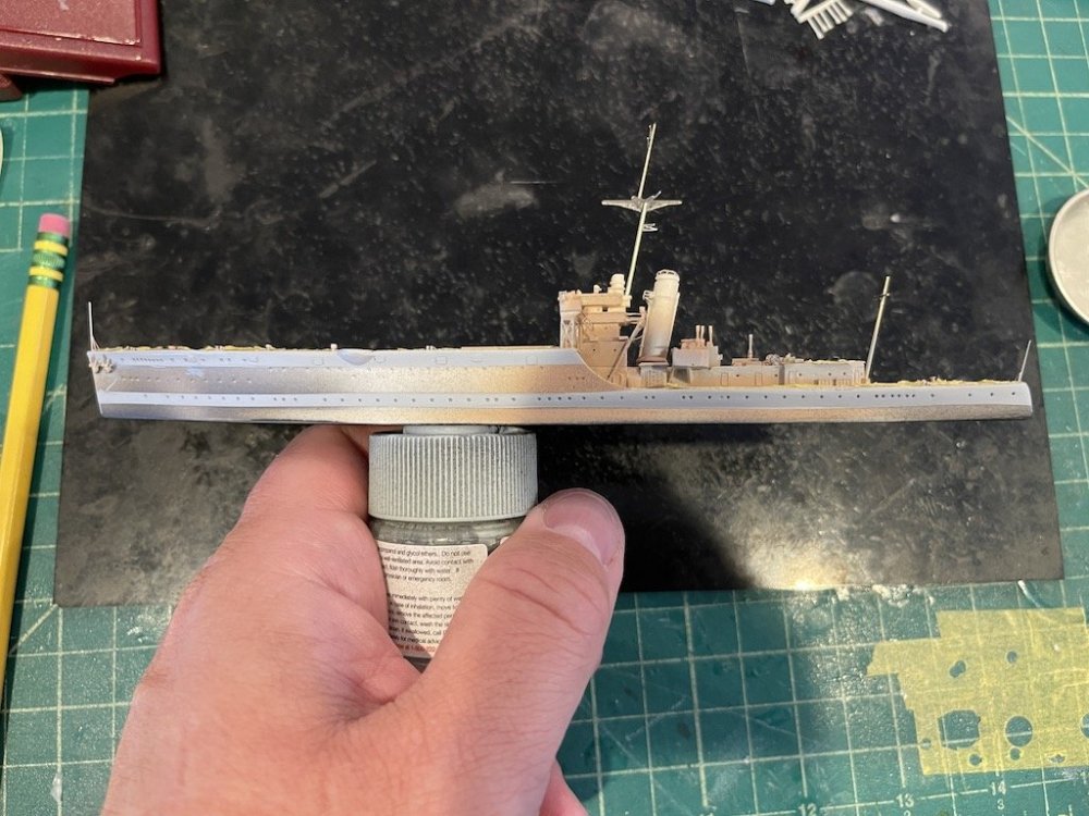
Next up I will clean up the hull plating lines and prime the full hull, deck structures, railings and other deck items using Mr. Surfacer 1500 black. That will give a good base to paint the ship, which is pretty simple with a light grey hull, and darker gray above the deck.
Thanks for looking in!
-
7
-
-
On 6/4/2023 at 3:46 AM, GazzaS said:
Doing a great job on both kits. PE slows me down... I really dislike working with it, so often find other things to do than sit at my bench.
Thanks! I just treat the PE as kits within the kit, as oftentimes it can be like an origami puzzle. 👍
-
Excellent Peter! Great start. Looking forward to your stampede!
-
1
-
-
1 hour ago, Peterpools said:
Mike
Just catching up and thoroughly enjoying your work. I'm just amazed at the level of detail you have achieved on both kits.
Thanks Peter, really appreciate the kind words. All the credit for the details go to the kits and aftermarket - I'm just trying not to screw it up too much.
Now I just hope to finish this all before the end of the month for the Group Build. Is going to be awfully tight 🙁
-
1
-
-
Wow, that looks fantastic!!
-
2
-
-
On 5/26/2023 at 12:25 PM, Peterpools said:
ebay - auction win:
Still shrink wrapped and brand spanking perfect! 🏆

Think Midway but don't forget the movie: Dive Bombers with: Fred McMurray, Errol Flynn, Ralph Bellamy and Alexis Smith and the movie was in full color. released in 1941.
Hey Peter, great subject! I have a build log going on the sister site in case you have any interest in seeing aftermarket and construction issues. Make sure you take a look to see if the fuselage halves have an indentation between the rear cockpit and the tail. Common issue in these kits. Otherwise, it's a really nice kit of a rarely modeled subject.
https://modelshipworld.com/topic/28510-sb2u-1-vindicator-by-landlubber-mike-accurate-miniatures-148/
-
2
-
1
-
-
Looking great Bill! Look at all that detail!
-
3
-
-
Wow that came out really nice NPB!! I was going to paint mine as a yellow wings version, but I might reconsider after seeing yours. What paints did you use for the NM finish? Looks excellent.
-
2
-
-
Hope everyone had a nice Memorial Day weekend, at least for those in the US and other places around the world where this important day of remembrance is observed. Thank you to all our veterans!
I managed to find some time this weekend to move the Albatross along. I have to say that I'm very impressed with the kit. The resin parts are very nice, and the PE is very well done for great details. Everything fits together very nicely, and seems to be accurate relative to the real thing from the sources I have.
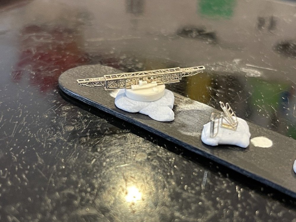
I decided that I'm going to install the deck items after painting the deck, as I think in the long run it will be easier, particularly with some of the hard to reach areas on the build. So, I primed the deck with a thin coat of Mr Surfacer 1500, then sprayed the decks with Tamiya Deck Tan. I also started to work on the main mast. My kit didn't include the rod for the main or rear masts, so I used 0.8mm rod for the main mast and installed the PE for the crows nest and other details. There is an upper section of the mast that needs to be included as well - I have some 1/700 aftermarket mast sections that I'm hoping will work.

I also worked on assembling the catapult components. The kit allows you to built the catapult extended or retracted. I built out the extended version which I think will match up with the extended version of the NeOmega catapult I'm planning on building for the 1/48 Walrus. Here's a picture of the guns, cranes, and catapult parts that will be painted and then separately added to the model after it gets painted.
Next steps are to finish building the main and rear masts, and rather than use the 2D PE parts for the bow and stern posts, I will scratch build them for a three-dimensional look. At that point, I can start painting the hull - light grey for the hull sides, and a darker gray for the sections above the decks.
Thanks for looking in!
-
5
-
1
-
-
30 minutes ago, KevinM said:
Well that is looking awfully Good there Mike.The PE on the 1/72 Walrus looks like you have reached Master Status Sir!

Thanks Kevin, really appreciate it! I'm slowly getting better at PE, and still have room to improve. It really helps to have the right tools - Optivisor, very fine tweezers, and a good hold and fold unit (I have the Bug and one of the larger units from The Small Shop which I highly recommend).
-
1
-
-
Yikes, that's quite a gap. Can I ask how you made that plug? Is it a solid piece? If so, did you laminate a bunch of plastic sheets together or are you running thin plastic card around a wooden/clay former? Just asking as I don't know that I've seen plastic card available in such a thickness. Looks great so far!
-
3
-
-
2 hours ago, Bomber_County said:
Amazing workmanship on both kits, the Walrus looks great……
Thanks BC, really appreciate the kind words!
-
1
-
-
5 hours ago, belugawhaleman said:
A trip to my local Ace Hardware resulted in this purchase......
Tamiya's Grumman F4F-4 Wildcat (61034) in 1/48.
Not armor, or large-scale......but ,still a nice little kit.
I have a couple of the 1/32 Trumpy kits of this.....but
I know this will be a smaller , Yet less frustrating build.
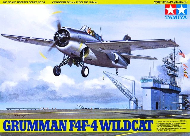
I enjoyed building this kit - goes together really nicely. I added a bunch of AM to it, but even without AM builds into a great model.
-
3
-
-
Thanks Hubert! The Walrus weren't too bad. I had to run them under hot water to straighten out the wings a bit, but other than that, the hardest thing was not losing the tiny things like the floats and tail wings.
For the nose, I think part of the look is an exaggeration from the extreme magnification, part is that the kit is trying to show the gun in the front turret. I'll have to figure out if I want to keep it or not, thanks for pointing it out.
-
1
-
-
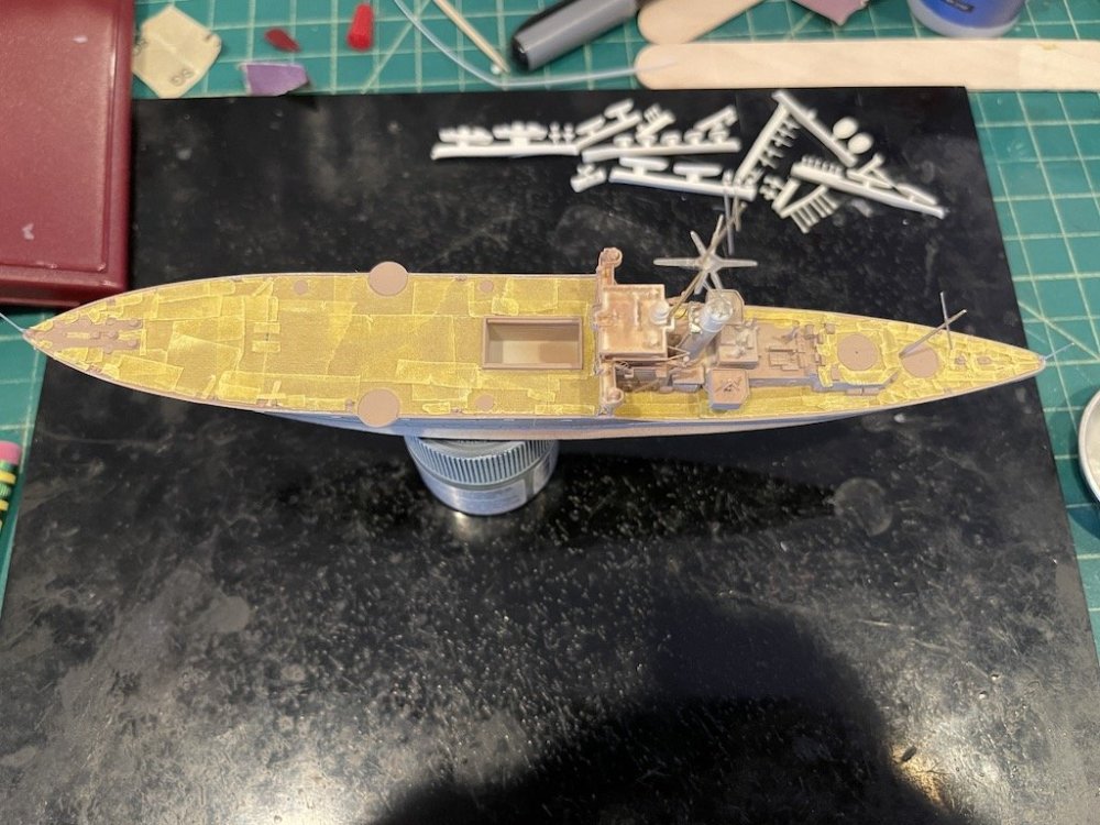
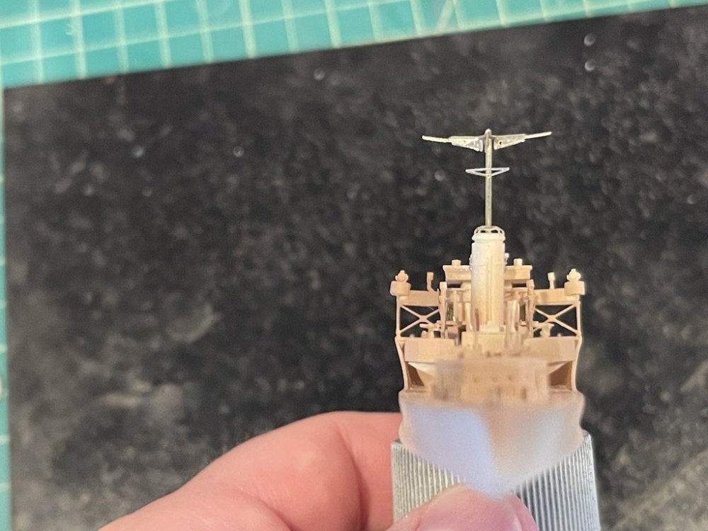
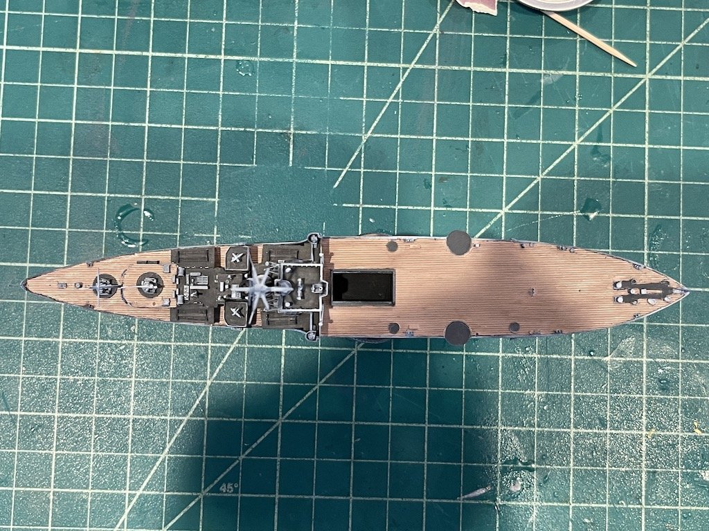
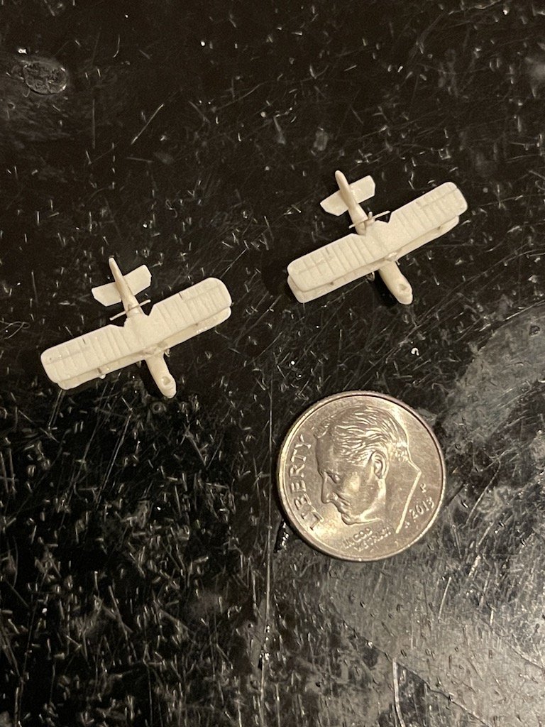
I made a lot more progress on the Albatross the past few nights. Managed to get the bridge completed, and added a bunch of other items to the rear half of the ship. I changed my mind and am going to paint the deck before adding all the various deck items. Part of the issue is that if I put on some of the platforms, I really won't be able to paint the deck underneath. Plus, a lot of the deck items are resin with their bottoms attached to the plug, so I can paint them off the model, cut them off, and then glue them onto the deck - at least that's the idea.
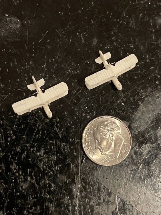
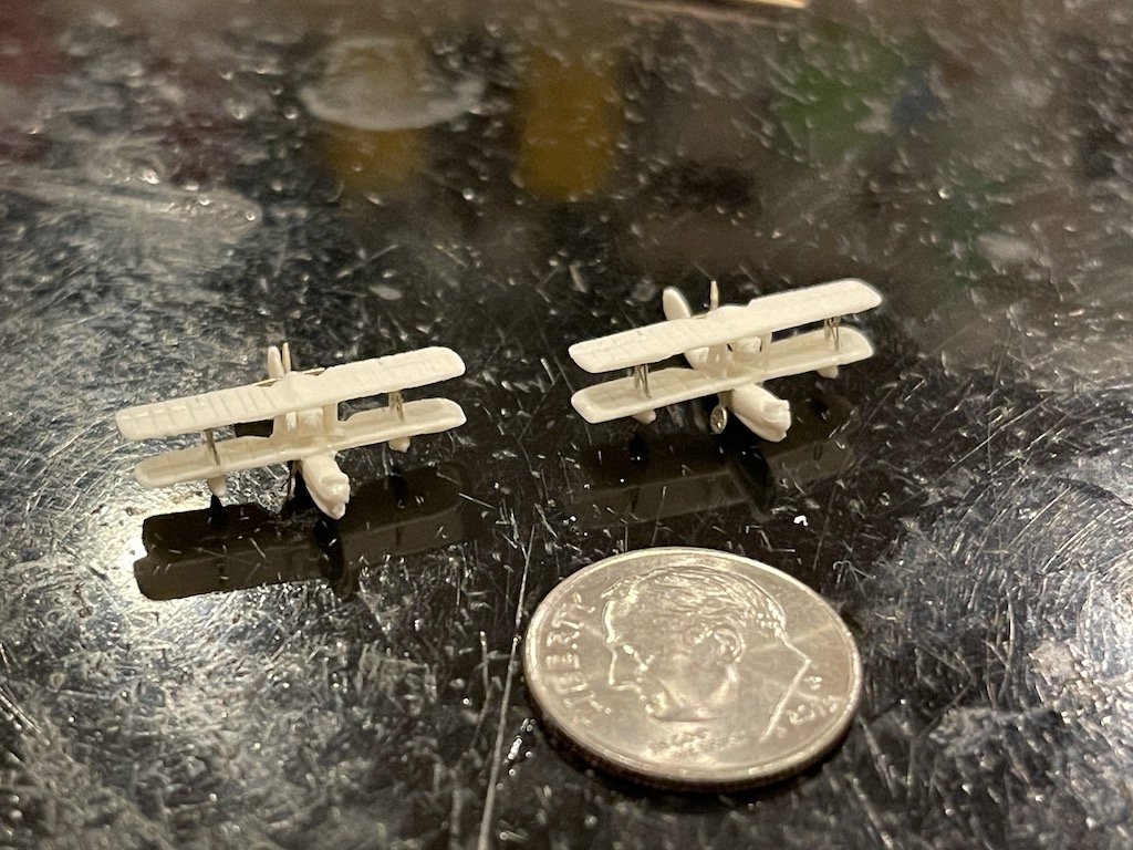
Next I worked on the Walruses. I probably only need one, but built the second up as a spare. I thought building a biplane in 1/72 was tricky - at 1/700, it's a completely different story! Good practice for future builds I suppose as I have a few 1/700 aircraft carriers in the stash.

Thanks for looking in!
-
6
-
-
Nice! Looking forward to this one. I love 1/700 models.
-
2
-
-
Wow, what a fantastic build Peter!! Beautiful work!
-
1
-
-
Wow, really nice looking model there Kevin. Great job!
-
1
-


Walrus (Airfix 1/48), NeOmega Catapult, and HMS Albatross (Niko 1/700) by Landlubber Mike
in Let’s Get Wet Group Build.
Posted
Thanks guys, really appreciate it! There's still a lot of goodies to add to the decks. So far I'm pretty pleased with how it's coming out.