DocRob Posted January 19, 2025 Author Posted January 19, 2025 On 1/17/2025 at 10:54 PM, ScottsGT said: Jeeze, I’m having flashbacks of building my 1:1 scale ‘66 Mustang. My body panels are all custom fitted with exact gaps. Nothing like the crap Ford put out back in the day. It´s nearly the same with this one, except, I can handle it with one hand, luckily. For a kit it is no lightweight though. I´m not sure, if exact gaps where to be found on the real one, as they were build up in great haste. Cheers Rob 3
DocRob Posted January 19, 2025 Author Posted January 19, 2025 23 hours ago, Bomber_County said: Good lighting, eyesight and steady hands is the order of the day and plenty of patience. Hats of to you Rob, when I rebuilt my Truimph GT6 Mk III (1:1) it had an E Type bonnet, at that scale it was a pain to align so at 1:12 wow……. Thanks Phil, with the Cobra, it´s the phase of the build, where everything has to come together and where all the tolerances and little errors show. I will find a way to get it done. Your Triumph must have been a nice one, but exact gaps were never one of the greatest virtues with British cars. Cheers Rob 3
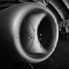
DocRob Posted January 24, 2025 Author Posted January 24, 2025 Poco a poco (little by little, like they say here where I live. I forgot to include the engine firewall into my final? assembly check. Getting everything together with the firewall, is extremely delicate, like a 3D puzzle, but after a lot of shuffling and breaking some pats off, it fits. Next, I reworked the areas of the bonnet, which connect with the chassis hinges for a better fit. Some modifications of the existing parts were needed. I also tested, how I could fit my first vac formed window in place with double sided transparent adhesive tape, which didn´t look promising at all. I need some better tape and luckily my wife flies to Berlin next week, where it is easier to get hold of better stuff. Finally, I found another method to lower the obstructing first cylinder funnels a tiny bit for a better bonnet fit. I removed the PE seal? under the aluminum funnel with a sharp blade and deepened the holes, which accept the funnels first with a 2 mm drill bit, then the outer diameter with a 3 mm drill bit (left side without PE and drilled out). As you can see, the front left funnel sits a bit less than a millimeter deeper, than the others. Not a lot, but it sure helps. I reglued the funnels and the rivets besides and like the result. You have to know, that something is missing to find it. Cheers Rob 9
Martinnfb Posted January 24, 2025 Posted January 24, 2025 Great progress Rob, with some insane detail, for a second I thought it's the real engine. 3 1
Landlubber Mike Posted January 24, 2025 Posted January 24, 2025 Looks great Rob! Nice work on finding a way to lower the cylinders. Nobody is going to notice that fix with all the detail with the engine. I'd rather do that than mess up the hood trying to shave it down for clearance. 3 1
DocRob Posted January 25, 2025 Author Posted January 25, 2025 21 hours ago, Martinnfb said: Great progress Rob, with some insane detail, for a second I thought it's the real engine. Thank you Martin, if it would be the real engine, I would be rich . MFH engines are the best you can get and great fun to build. They have separate engine kits in their portfolio, but that is too much special interest for me. Cheers Rob 4
DocRob Posted January 25, 2025 Author Posted January 25, 2025 20 hours ago, Landlubber Mike said: Looks great Rob! Nice work on finding a way to lower the cylinders. Nobody is going to notice that fix with all the detail with the engine. I'd rather do that than mess up the hood trying to shave it down for clearance. Thank you Mike, but I already milled and sanded away as much as possible from that area of the bonnet. It is now paper thin. Cheers Rob 6
DocRob Posted January 27, 2025 Author Posted January 27, 2025 Today, I prepared all the parts, which will be added to the firewall. Again lots of cleanup work and naturally drilling holes for mounting the parts and adding tubes and hoses later. Besides, I added tiny magnets to the rear hatch and the doors. The magnets have a diameter of 2 mm and are 1 mm thick. The doors were pre-drilled with a 2 mm drill bit and cautiously finished with a 2 mm milling cutter, to not drill through the door with the drill bits front cone. You can see the magnet shine through in the doors side view, it was close. The magnets will definitely help, to keep the doors in aligned in good position when closed. Cheers Rob 9
BlrwestSiR Posted January 27, 2025 Posted January 27, 2025 Some great work and problem solving there as always. Like Martin said, the engine looks real. 5 1
DocRob Posted January 27, 2025 Author Posted January 27, 2025 6 hours ago, BlrwestSiR said: Some great work and problem solving there as always. Like Martin said, the engine looks real. Thank you Carl, I hope, I don´t need to chop of more parts, to get the bonnet fit. With a few more steps, I think the painting stage is on the horizon. Cheers Rob 2
HubertB Posted January 27, 2025 Posted January 27, 2025 Ingenious solution for the doors, Rob. The fit is now better than on the original Hubert 3 1
CANicoll Posted January 27, 2025 Posted January 27, 2025 Amazing work, Rob both on the intake funnel issue and then the doors and magnets. Just superb. Love following along with your work. Agree with Hubert, the fit is better than the original! 2 1
Landlubber Mike Posted January 27, 2025 Posted January 27, 2025 Really impressive work there Rob. Love the magnet approach! 2 1
DocRob Posted January 28, 2025 Author Posted January 28, 2025 14 hours ago, HubertB said: Ingenious solution for the doors, Rob. The fit is now better than on the original 13 hours ago, CANicoll said: Amazing work, Rob both on the intake funnel issue and then the doors and magnets. Just superb. Love following along with your work. Agree with Hubert, the fit is better than the original! 12 hours ago, Landlubber Mike said: Really impressive work there Rob. Love the magnet approach! Muchas gracias amigos, I hope, I will not overdo it with my unrealistic even gap approach . I know, the originals were build up in a hurry and I guess, perfect fit was not the utmost goal. Finally there will be enough potential for errors and I will eliminate as many as possible before entering the painting stage. Cheers Rob 6
DocRob Posted January 31, 2025 Author Posted January 31, 2025 Hopefully these are the last preparations before entering the painting stage, but as often, there was one step back, before advancing. I had to remove the already installed internal framework and internal rear view mirror, because they would have interfered with masking the inside of the body later. I finalized cutting the transparent air scoop vac parts with a pair of fine scissors, sanded them to fit and dry fitted them for drilling holes for the rivets. The first side, I drilled with a 0,6 mm DSPIAE drill bit, which tended to lift up the clear part, when drilling through. I changed to a Tamiya 0,6 mm drill bit for side two and got much better results. No lifting and dramatically less burr, which is a pain to remove with these clear vac parts. When you compare the drill bits, the Tamiya is of the classic HSS style and angles, where the DSPIAE bit is like all the other PCB board drill bits and not good for drilling thin materials, as it "eats" into the material and leaves a lot of burr. Cheers Rob 8
HubertB Posted January 31, 2025 Posted January 31, 2025 The other difference is that the PCB drill bits are of a different steel grade, richer in carbon … Hence their propensity to break like glass … Hubert 3
DocRob Posted February 1, 2025 Author Posted February 1, 2025 17 hours ago, HubertB said: The other difference is that the PCB drill bits are of a different steel grade, richer in carbon … Hence their propensity o break like glass … Absolutely Hubert, I forgot to mention the buggers are absolutely brittle and break sometimes when you drop them on the workbench. Unfortunately it seems hard to find good HSS drills with small diameters in larger quantities. I once bought a box from China with drill bits from 0,3 mm up to 2,5 mm. Not expecting much, I was disappointed even more, as the smaller ones were only cut from a blank, seemingly with a wire cutter. They had no tip at all. Cheers Rob 4
DocRob Posted February 6, 2025 Author Posted February 6, 2025 The painting stage has finally begun . I cleaned all the resin body parts in warm soapy water with a large brush and sponge first and then primed everything with Mr. Surfacer 1500 grey. After drying, I sprayed the white sections with Tamiya´s XF white (bonnet inside and firewall and small parts of the main body) These areas got masked then. Finally, I sprayed two jars of Tamiya´s excellent LP-5 semi gloss black onto the inside of the wheel wells... ... and the inside and window framing of the body. Some interior parts got also sprayed during that session. Next will be an intense masking session for the interior and a lot of praying, there are no paint lifts after. Cheers Rob 8
BlrwestSiR Posted February 6, 2025 Posted February 6, 2025 The painting has begun. Can't wait to see your magic on this. 4 1
DocRob Posted February 6, 2025 Author Posted February 6, 2025 2 hours ago, BlrwestSiR said: The painting has begun. Can't wait to see your magic on this. 1 hour ago, CANicoll said: 1 minute ago, Landlubber Mike said: Thanks Carl, I hope it will not lead to four trials, like with your Beat. I have only three jars of the body blue metallic. Chris and Mike, don´t come too close with your crumbling popcorn, which will ruin my paintjob Cheers Rob 5 2
DocRob Posted February 8, 2025 Author Posted February 8, 2025 After an intense masking madness session, to protect the interior, I started with the body color. I fear, there will be color lifts with the interior, despite cleaning the resin properly, thorough priming and airbrushing, but this needs to be addressed later. It´s also one of the reasons, why I didn´t mount some of the ready painted inner fairings, before painting the body. A Kind Of Blue from Miles Davis was my soundtrack for the paintjob I used Number Five´s Cobra Blue as the main color. Other than with classic plastic kits, I had not to fear reactions with the resin and could coat a bit more liberal. I airbrushed three medium coats with a drying time of about 20 minutes in between. Number Five colors are ready to spray, but I added about a third of leveling thinner after some testing. They spray very fine and even, with extremely fine metallic grain and dry semi matte and fast. At first, I thought, coverage would be not too good, as the black overspray shined through the first coat, but after some minutes, the paint leveled and became more opaque. Besides the horribile smell, (I always wear a respirator) I absolutely love my first experience with Number Five colors. Besides, I used only one 30ml jar of color for the big Cobra, which is great to my eye. After checking, I found some tiny dots on the bonnet and will lay on a fourth coat tomorrow. Cheers Rob 10
FullArmor Posted February 8, 2025 Posted February 8, 2025 21 minutes ago, DocRob said: After an intense masking madness session, to protect the interior, I started with the body color. I fear, there will be color lifts with the interior, despite cleaning the resin properly, thorough priming and airbrushing, but this needs to be addressed later. It´s also one of the reasons, why I didn´t mount some of the ready painted inner fairings, before painting the body. A Kind Of Blue from Miles Davis was my soundtrack for the paintjob I used Number Five´s Cobra Blue as the main color. Other than with classic plastic kits, I had not to fear reactions with the resin and could coat a bit more liberal. I airbrushed three medium coats with a drying time of about 20 minutes in between. Number Five colors are ready to spray, but I added about a third of leveling thinner after some testing. They spray very fine and even, with extremely fine metallic grain and dry semi matte and fast. At first, I thought, coverage would be not too good, as the black overspray shined through the first coat, but after some minutes, the paint leveled and became more opaque. Besides the horribile smell, (I always wear a respirator) I absolutely love my first experience with Number Five colors. Besides, I used only one 30ml jar of color for the big Cobra, which is great to my eye. After checking, I found some tiny dots on the bonnet and will lay on a fourth coat tomorrow. Cheers Rob Impressive color. This is gonna be great👍. I can't wait 3 2
BlrwestSiR Posted February 8, 2025 Posted February 8, 2025 That looks great Rob. Looks very smooth. More importantly, it's dust free. 1 1

Recommended Posts
Create an account or sign in to comment
You need to be a member in order to leave a comment
Create an account
Sign up for a new account in our community. It's easy!
Register a new accountSign in
Already have an account? Sign in here.
Sign In Now