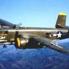
av8shunmodels Posted March 11, 2013 Posted March 11, 2013 This was started Feb 4th, my birthday on LSP, I'm moving the contents of the thread to here and will update posts at both sites. In this online build I will be building a "to be determined" version of the excellent HK Models B-25J glass nose version. I may do either a Crusader or Air Apache version and haven't decided on NMF or OD/Gray, I have PLENTY of time to decide as the insides will be the same either way. There are a few "issues" with the kit but some may elect not to deal with them. If you are a nit picker/ rivet counter or just REALLY love the B-25 you'll want to address the following issues: ( I just really love the B-25! ) NOTE Do not take this as a slam of the HK kit, I'd buy 5 more if I had unlimited funds and I am quite sure a great model can be made almost out of the box. I am simply pointing out obvious omissions for those who wish to go the extra mile and 3/4. OK this is the list of things I am planning to correct, there may be more: There is VERY minimal detail in the flight engineers/ top turret gunners position, no radio racks, no ammo feeds or charging handles for the "cheek" gun pods, no hydraulic accumulator, no wiring harness or box's, a whole "deck" of structure is not present, the rib detail is not repeated as it is in the cockpit so if you want to add it you're in for some work. There are no heater units or ducting for the forward or rear fuselage.There is no "tunnel" leading into the nose position so if you doing either version and want to see up into it from below you better be prepared to do a fair amount of scratch work or just live with the "void" The exterior perimeter of the top turret is not correct, see detail pics to see what I'm talking about. The leading edge of the wing doesn't not have the heater intake duct, the prominent "bolts" on the leading edges of the wings are missing, the landing light openings are to large. The life raft compartment that should be visible in the rear fuselage compartment is missing, all the folding seats are missing, there is no strike camera or opening for it in the lower fuselage, and most of the supporting structure for the main landing gear would have to be built unless you don't mind looking up into the wheel bay and seeing bare plastic and the mounting stud for the main gear legs. The interior structure in the rear fuselage is generally in the correct locations, but it needs substantial fleshing out as well as the proper floor structure installed. None of the canvas spent cartridge casing bags are present. The sextant and gun sight as well as the ring and bead back up sight is missing too. I will be addressing all of these issues. Suffice it to say, that if one really wanted to go all out and make a giant cut away model this one lends itself to that really well! To start with I have: HK's Kit, Eduards PE sets for the nose, cockpit, interior ( main fuselage ) and bomb bay Brassin Wheel set G Factor metal landing gear Profi-modelers sets for the antennas, and their brass gun barrels A few billion linear feet of various widths of strips and shapes polystyrene ( ok, maybe a little less ) Just shy of a billion linear feet of various gauges of wire, solder etc. ( Teresa says "I never throw anything away" ) AMS Resin's Excellent crank case and propeller blade replacements HGW's seat belts Various rivet decals from Archer About a dozen reference books to go along with the MAAM link posted above, but those are just in case as the website has almost all of the stuff I have in books and online. So here is a quick shot of some of the "stuff" ( not all of it is pictured here,it's already on the bench ) OK, so one of the first things I did was glue in the Eduard "structure" parts for the pit and check it with some Tamiya gray primer. First the lugs and plugs they locate into need to be removed to properly use the PE in the pit. some of the molded in details need to be removed as well. I also set about to scratch build the details in the tunnel. This area is still being refined and detailed, but I'm pretty happy with it so far, although you will hardly see any of it. I sheeted everything with .005 styrene and used RB productions rivet tools to add rivets.( hopefully they will show up under paint. I noticed some slight distortion in the molding of the forward nose area, and the rivet lines ghosted in and out in spots, so I had to fix that. Here are the sides I had to re rivet, I ended up using Radu's Rivet tool/wheel with the 1MM wheel installed, perfect match to my eye. Here are a couple of the brass interior parts so far. I'm trying to add the parts of these various sets that have to be interior green and then add the rest that are black after the interior color is on. The seat base on the ammo box's is just sitting there,not glued on yet.
av8shunmodels Posted March 11, 2013 Author Posted March 11, 2013 Test Fit of the engines, Test fit of the Gun pods and dry fit Profi Modeler barrels, the pods them selves seem to sit to low and the deflection of the barrels is a bit to extreme, should be 2-4 degrees down angle, both will be adjusted when I get there. Left is HK, Right is AMS resin..the AMS parts are shaped correctly and the profile from the side is scale thin, really nice work Harold! Now the crank case, please excuse my crappy pics but you'll get the point.. AMS on the Left HK on the Right, AMS's part much more closely represents the correct crank case in shape and relative size, they should look excellent when they are applied.
av8shunmodels Posted March 11, 2013 Author Posted March 11, 2013 I cant believe the engine took all dang day, and its still not done, but here is a pic of the front ( what you'll see in the cowling opening) I don't think it turned out half bad, I just hope I can get the other one to match! I'm going to knock out the building and painting of the other engine tommorow, may as well get it done! I decided to use .020 solder instead of the kit parts for the wiring, still have to add some parts to the crankcase and wire looms.
av8shunmodels Posted March 11, 2013 Author Posted March 11, 2013 Well, Somehow I got them to match..Two for the road! Err.. The wings! Here are a couple of Pics of the Eduard "Brassin" tires and wheels I painted up this morning, really nice addition to the kit I think. I made my own home brew rubber tire color, washed with Pro Modeler Dark dirt in the treads. The wheels themselves are a combination of Floquil "old silver" and Alclad "airframe aluminim", with a light Tamiya "smoke" wash around the details. So I am detailing or will be detailing everything behind the flight deck as closely as possible to the original. This required me to modify the bomb bay insert to do what I have in mind. The first couple of pics are the modifications I made to the bomb bay so far, you can see the cutting lines marked in pencil. I also traced the outline of the frame behind the flight deck to use as a template for more internal frames to be added in in a bit. Here is the forward part of the bomb bay modified so far, this will be "skinned" with plastic and details applied to it.once the internal section is all painted up and assembled.
av8shunmodels Posted March 11, 2013 Author Posted March 11, 2013 I got all the rest of the Eduard set in the bomb bay, and primed and shot duraluminum on the surfaces. The rest of the wiring etc. will be done over the weekend. There is a quite extensive amount of extra wiring I will do especially on the forward bulkhead per the prototype, but I wanted to get the tedious part of this done first so I can have some fun! Here are some pics of where I stopped for the night. First I had to modify the hatch interior ( the little round thing with 4 raised gussets and a latch ) per the prototype. Eduard gave me details to use here but they didn't match my references, so I made one and used their latch. Here it is painted prior to weathering, The sides of the bay..These will get more wiring and "lines" The bulkhead ends..Again, more wiring and plumbing to come as well as a wash and some weathering.
av8shunmodels Posted March 11, 2013 Author Posted March 11, 2013 Bomb bay is still a WIP ( more wiring and detail painting, weathering etc). I did give it a nice Tamiya "Smoke" pin wash and painted in the details that come molded on. I wanted to show you how much adding the kit supplied bomb load fills the bay. The other bomb bay details like the doors etc are worth the money but all that work inside is basically gone. I picked my best two bombs for the bottom row, you cant see most of the other 4 once everything's buttoned up. I'll have to get the random piece of hair out of the clear coat on the ceiling of the bay Here's some pics,
av8shunmodels Posted March 11, 2013 Author Posted March 11, 2013 OK so here is the before, as supplied by HKM, shot Alclad "duraluminim" with a Tamiya "smoke" wash. The after, once I was done with all the "fun". Seats, Cushions done in Milliput, belts are HGW and have since been "refined" they were a bit sloppy on the shoulder straps.
av8shunmodels Posted March 11, 2013 Author Posted March 11, 2013 he pics below are of the slightly modified Eduard instrument panel ( I added the correct yellow line around the critical flight instruments, pilots side) and as promised a couple of pics of how I hid 4 Oz's of weight below the flight deck and another 2 Ozs. behind the instrument panel. I did it this way so I didn't have to sacrifice "space" for details in the nose wheel bay ( something you wont really ever see, but I'm going to add some rudimentary details just for my own sense of fun.) What you don't see in the pics is where I hid the rest of the weights to bring the aircraft up to a nose heavy profile. I have an additional forward 1/4 of each Engine Nacelle FULL of weights hidden behind a fake firewall that are about 8 Oz's each, and each of the six bombs in the bay with weights in them total another 2 Oz's. This will allow me to add details to all areas of the aircraft without having to worry about being a tail sitter, and thank-you Ernie G for making such stout brass landing gear or this would probably not have worked out this well. The weights I used are self adhesive, come in 1/2 Oz "blocks" connected 8 long and are used commercially for tire weights for your car, In R/C Aircraft and model railroading. I got mine from my LHS and they are sold by A West for model train weights. The first pic is of the Instrument panel..Macro Zoom allows for no evil to be hidden, but thankfully the naked eye is much kinder on my work, either that or the paint fumes are blurring my vision just enough I think it will pass? The little red " buttons" on the pilots flight control yoke are the bomb and gun buttons, they will get a little more detailing shortly. There is also an instrument panel lighting switch just to the left at the top of the pilots wheel, it's pretty hard to see in the pic, but its there. I need to attach two "grimes" lights that are mounted on the right side of the columns as well, they are made, just not installed yet. The second pic is the copilots side showing the weights hidden beneath the flight deck and then covered with .030 sheet styrene to form the ceiling of the nose gear bay, I will detail the interior of this out later today. Next pic is of the pilot's side, Thankfully doing my weights this way allowed me to have a fully detailed "tunnel" under the flight deck, well it will be soon enough. As I said earlier in the post, it should actually have a "kink" in the profile going forward, but you wont see it so I went the easy route and just made it straight. You can also see the weights sitting up behind the control panel. I blocked off the area behind the rudder pedals with more plastic after leaving a .090 space behind them so there is realistic depth and shadow, you'll never see it but it's worth mentioning. I also wanted to point out that there is still room for more "hidden" weights under the floor on this side and a couple more up on top behind the panel, I don't need it but I may add a couple more just to be extra double positively sure This shot is looking straight down into the pit, and the dang flash is making my satin coat look like gloss..some day I'll learn how to light my pics better I hope. OK Last one, this shows the the seat back armor and head rests installed. The seat back armor should actually be a little wider then the seat, but I miscalculated, I can fix it before I install them or leave it.. I'll worry bout it later. I hope the weight placement I have shown and explained can help the next person with their build. It's a pretty easy to do method and leaves you no unsightly weights in areas you might want to dress up a bit. 1
av8shunmodels Posted March 11, 2013 Author Posted March 11, 2013 Then transfer the tape pattern to a piece of .010 sheet plastic, trace it, clean it up if need be, then cut it out. Now make another for the other side, they are identical. Test fit and refine if required. I used .010 because its minimal thickness allows it to easily bend into contours and isn't so thick it will cause problems later on trying to close the fuselage half's. Once everything looks like its going to fit, mark out your locations for the ribs, stringers and major bulkheads BEFORE gluing the new parts into the plane. This will give you more room to work, and keep everything "square" inside. Your can also pre- measure and cut your stinger parts in advance. Here are the new parts cut out and with the layout marks on them. Here they are glued into the plane. The last one for tonight shows how much of a difference adding that detail, even just the ribs and stringers and some bulkheads will enhance this VERY busy area of the B-25.
av8shunmodels Posted March 11, 2013 Author Posted March 11, 2013 For the side wall details I used the Eduard set, and made a couple of the correct shapes for the "box's" on the pilots side, Eduard got "close" but it appears they guessed on some of it. I used .010 and .015 wire, .010 and .015 plastic rod, and various miniature solder sizes to do the wiring, and the wire is run where it belongs according to the photos in the pilots manual and the MAAM B-25 Briefing Time. I twisted or braided .006 wire for the stranded cable and will add the wire clips next as well as a subtle wash to highlight the strands. I did not include any of the added items that wouldn't have been on a restored B-25 such as modern navigation or radio gear etc. The black box under the radio controls ( with the 3 sets of twin wires coming out if it on the Eduard set is wrong, so I made a new one to represent the correct configuration, and placed the Eduard panel on top, the one to its left is part of the war time fire extinguishing system and still needs to have its 3 "plungers" added to it. The area in the "tunnel" is still being detailed out, and I removed a black conduit that connects the miniature stranded wire that splits off into the control box and continues forward into the nose, and will make it more accurately shaped then I had it. On the Co Pilot side, a few smaller details need to be added. The flat square thing is a fold out table for navigation etc, and though it looks really cool on the restoration planes in natural wood, it would most likely have matched the rest of the low-viz interior at least initially until paint was shed from use. I used oils throughout to age the interior in a "restrained" fashion. My B-25J is a relatively new aircraft to the squadron I'm building it from and the time period it represents, so the entire cockpit and exterior is more realistically weathered in overall appearance to reflect this. This particular B-25 was delivered to it's squadron in October 1944 and was lost on a mission in March 1945, so it wasn't in terrible shape after 5 Mo's of service. Pilots side, Co-Pilots side,
av8shunmodels Posted March 11, 2013 Author Posted March 11, 2013 Today's update concerns the flight engineer/ turret gunners position. As I showed a few posts ago, I skinned the inside of the fuselage halves with .010 styrene, then marked out the locations for the stingers and ribs. I have now added those stringers and ribs and bomb bay bulkhead ( interior) wall detail. I painted starting with a pre-shade of Dull Dark Green, followed by Interior Green ( my own mix ) and lightly highlighted the center of each panel with highly thinned Flat Yellow. This area is still under construction because as stated earlier, there is a LOT of wiring and equipment that needs to be crammed in there with the turret mounted twin 50's, or "Bendix turret" and its associated hardware. What you see is the basic structure, ready for test fitting of the various breaker / junction box's, hydraulic accumulator and lines, corrected ammo box's for the fuselage mounted twin .50's and their feed chutes, control cables, radio rack and radios, dome light, flare gun port, jump seat, heater, various braces and larger sheet metal details, two armor plates, the roof support plate for the turret drive, etc, etc. I am making masters of the important detail items to be cast in resin so that when I do the next one I don't have to reproduce each one of these complicated assemblies by hand again. I will also treat the radio operator/ waist gunners position in the same fashion, making all of his equipment and detailing the center of the plane back to the tail gunners position as far as can be viewed through the blister windows and rear entry hatch. ( now you know why I made my nose end so heavy! ) Right now I'm finishing up the details for the forward parts so they can be cast. Rear Bulkhead Co-Pilots side Pilots side Looking inside What I am trying to replicate
av8shunmodels Posted March 11, 2013 Author Posted March 11, 2013 Sometimes you have to build a model to go on or in the model, and that takes time. Case in point, the turret. The kit offering is passable, ( though all of the kit's gun barrels are painfully to small in diameter and detail) but it is another one of those areas that's just crying to be corrected. So far my WIP turret has over 102 scratch built or aftermarket parts on it if you count all the steps to make the little assembly and bolts etc. I used the actual Tech Manual for the B-25 Bendix turret, dozens of pics and videos to try and get the thing to look like the real deal, and I'm getting there I think. The items that still need to be added are the "cages" that keep the operators appendages from being smashed that mount on each gun, the gun sight itself that sits next to the drive motor, a few more bolts and rivets, the shell collection bags that will sit below the spent shell casing chutes ( they still need to be modified ) the charging solenoids and various little box's, canisters and wiring that mount on the turret pedestal. The back support was made out of sheet aluminum and the 3 lightening holes drilled out. It also needs its rollers added that fit into the gun turret race ring at the base. The entire turret will rotate, but the elevation of the twin .50's is fixed. Finally, I'll add the ammunition itself over the two return rollers sitting between the guns and call it good. Once I had the turret this far, I needed to make sure modified parts fit, so I taped it all together to make sure So far it all fits!
av8shunmodels Posted March 11, 2013 Author Posted March 11, 2013 Almost done, Wont be long now and I'll be painting this little thing ( the turret not the plane!) The bottom of the turret dome itself sticks up to far out of the fuselage, this will be corrected when i mount everything inside the plane for good. 2
av8shunmodels Posted March 11, 2013 Author Posted March 11, 2013 Awesome work on the Mitchell! Thanks for the kind words Kojo, lots to do still but little steps lead to the top right? All the best, Paul
av8shunmodels Posted March 11, 2013 Author Posted March 11, 2013 Great Job! Congrats, Jamme Thank you Jamme! I am glad you like what I've done so far. All the best, Paul
Dave J Posted March 11, 2013 Posted March 11, 2013 Fantastic Work Paul! You are adding some fantastic detail! Looking forward to your next update.
Administrators JayDee Posted March 11, 2013 Administrators Posted March 11, 2013 All I can say is that I'm glad I'm more or less building WW1 now because this build would make me go out and buy this kit. Absolutely live the detailing and correction you've done. Will we see the B-17 next?
PAnderson Posted March 11, 2013 Posted March 11, 2013 Well, all I can say is wow. I had to stop reading and leave for work. I will come back to this later. There is so much detail and so much to learn I may have to read it more than twice. I am saving this. Nice work Paul, honestly. Paul
rkranias Posted March 11, 2013 Posted March 11, 2013 nothing like a little extreme detail work. really, really outstanding work on this and the extra effort with the scratch building is really paying off. this big Mitchell is going to be a beauty. watching for more...
wemattson Posted March 11, 2013 Posted March 11, 2013 Paul, Stunning! I'll be watching this one closely. Thank you for sharing. Wayne
Eighth Air Force Pilot Posted March 11, 2013 Posted March 11, 2013 I'm watching this in the hope I can summon the courage to build this beauty.. Nice work on the turret. You should build those and sell them!
harvey boyer Posted March 11, 2013 Posted March 11, 2013 Well, well, well, look who joined us ! good morning Paul , my friend ! You know I love watching............Harv
Grant Posted March 11, 2013 Posted March 11, 2013 Whoa !!! Paul, that's a fabulous build thread ... It's really worthwhile seeing some of those comparative shots between the kit parts and after-market parts too, it certainly highlights what you can get / achieve when you shell out on added items - accuracy and detail. << note to self .... HK models - consider adding to inventory ! >>

Recommended Posts
Create an account or sign in to comment
You need to be a member in order to leave a comment
Create an account
Sign up for a new account in our community. It's easy!
Register a new accountSign in
Already have an account? Sign in here.
Sign In Now