CrankyCrafstman
-
Posts
1,350 -
Joined
-
Last visited
Content Type
Profiles
Forums
Events
Gallery
Everything posted by CrankyCrafstman
-
 Hey Ernie It is a gem and will be really stunning when it is done, but it does have its flaws. Check out my other two posts on how to do the engine I think you will find them informative. Ron G
 -
Hey Ernie First I need to finish the bulid for the P&W R-2800-10W that goes in this kit. I already have an Airscale instrument panel set for it. I just purchased a 1/24 scale HGW p-51 seatbelt set for it (they were the same as the hellcat just a different color. I got a set of Master brass barrels for a 1/24 P-47 that I my use on it, the ones with no holes we'll see how it goes. Ron G
-
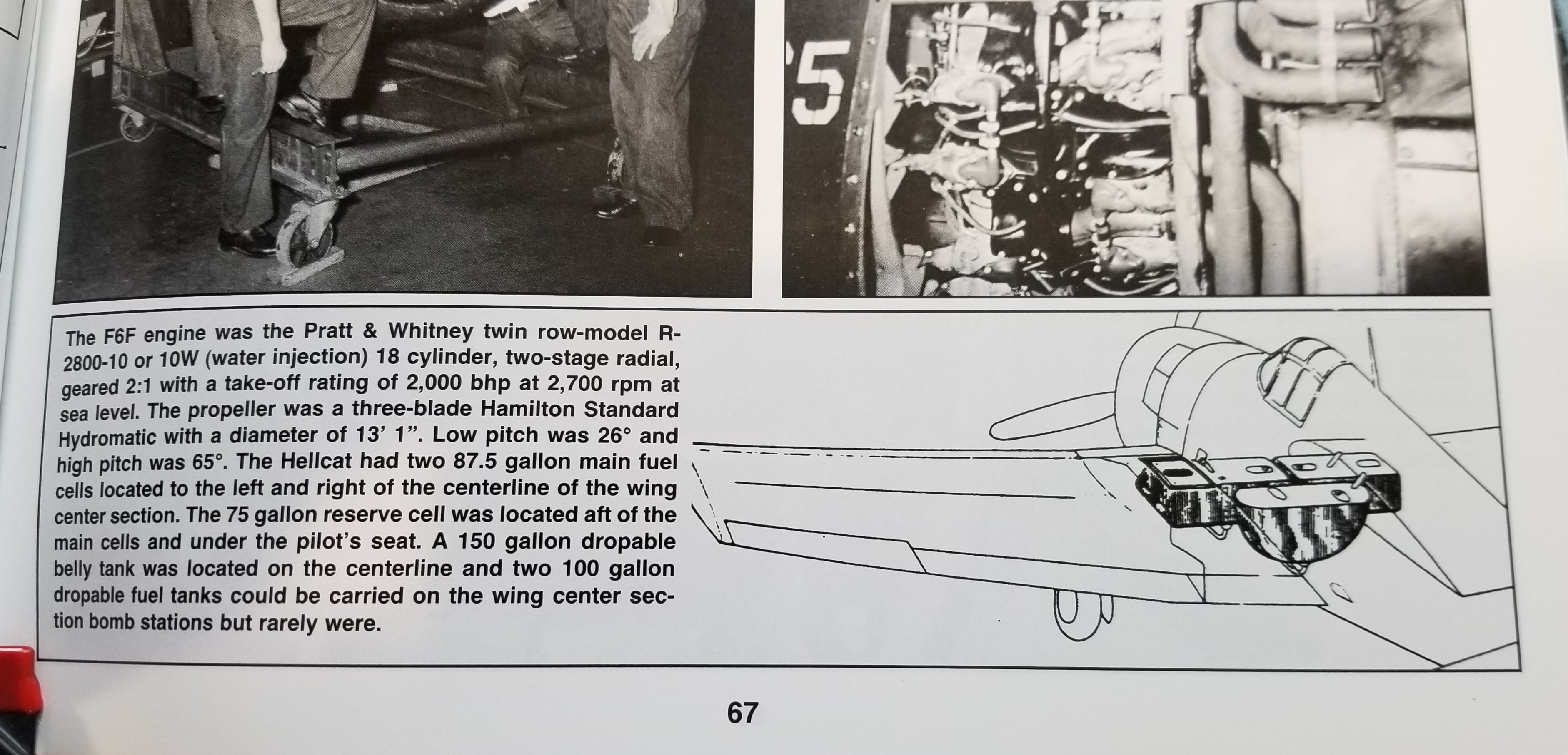
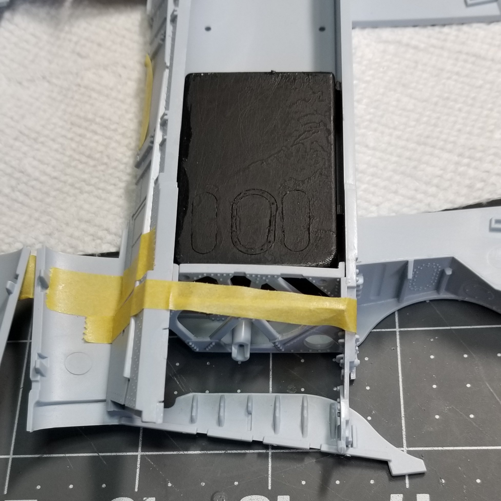
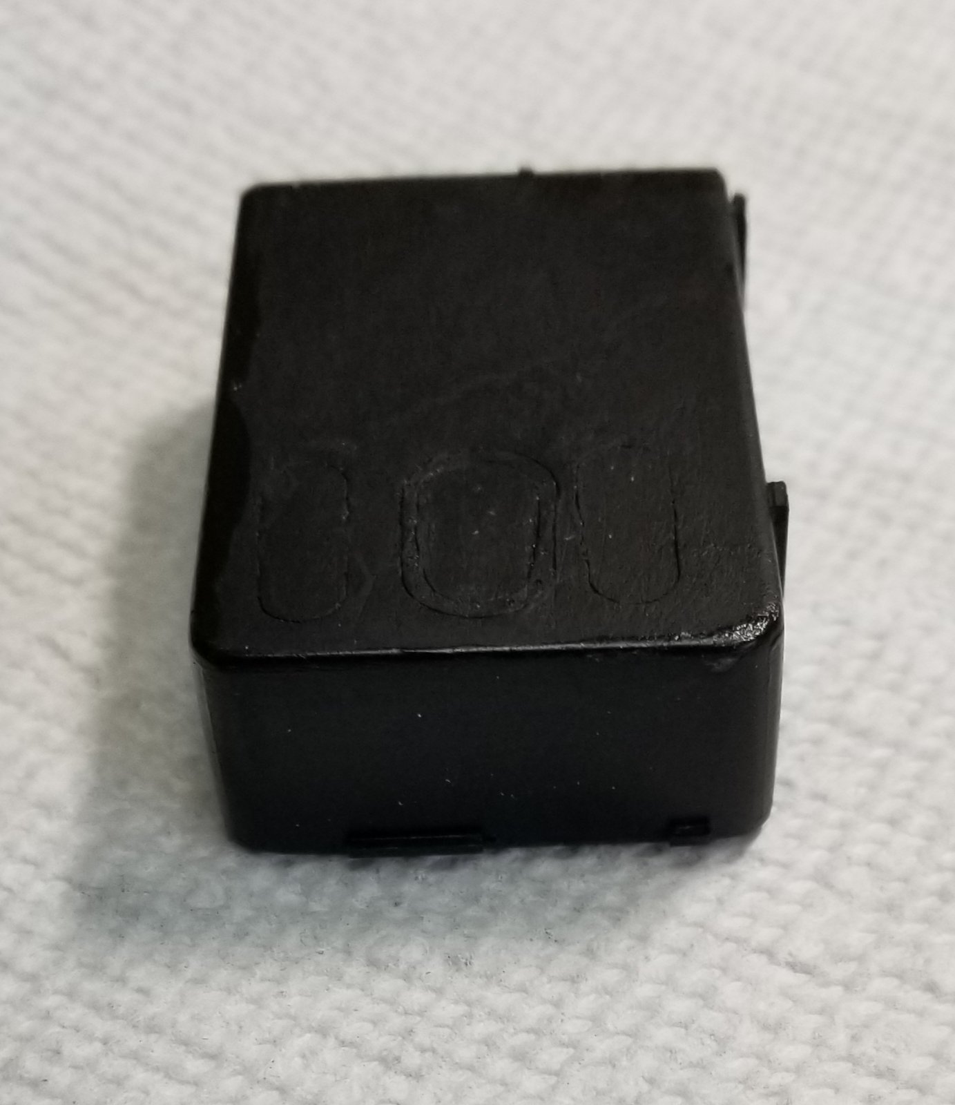
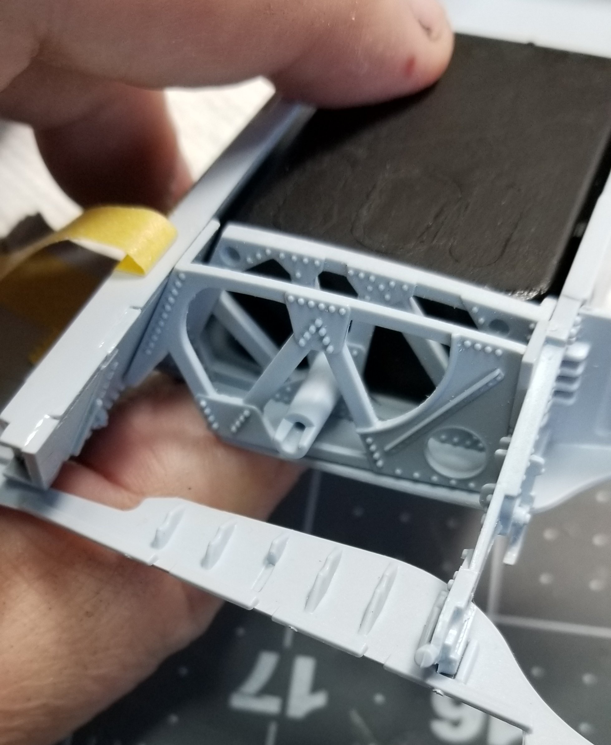
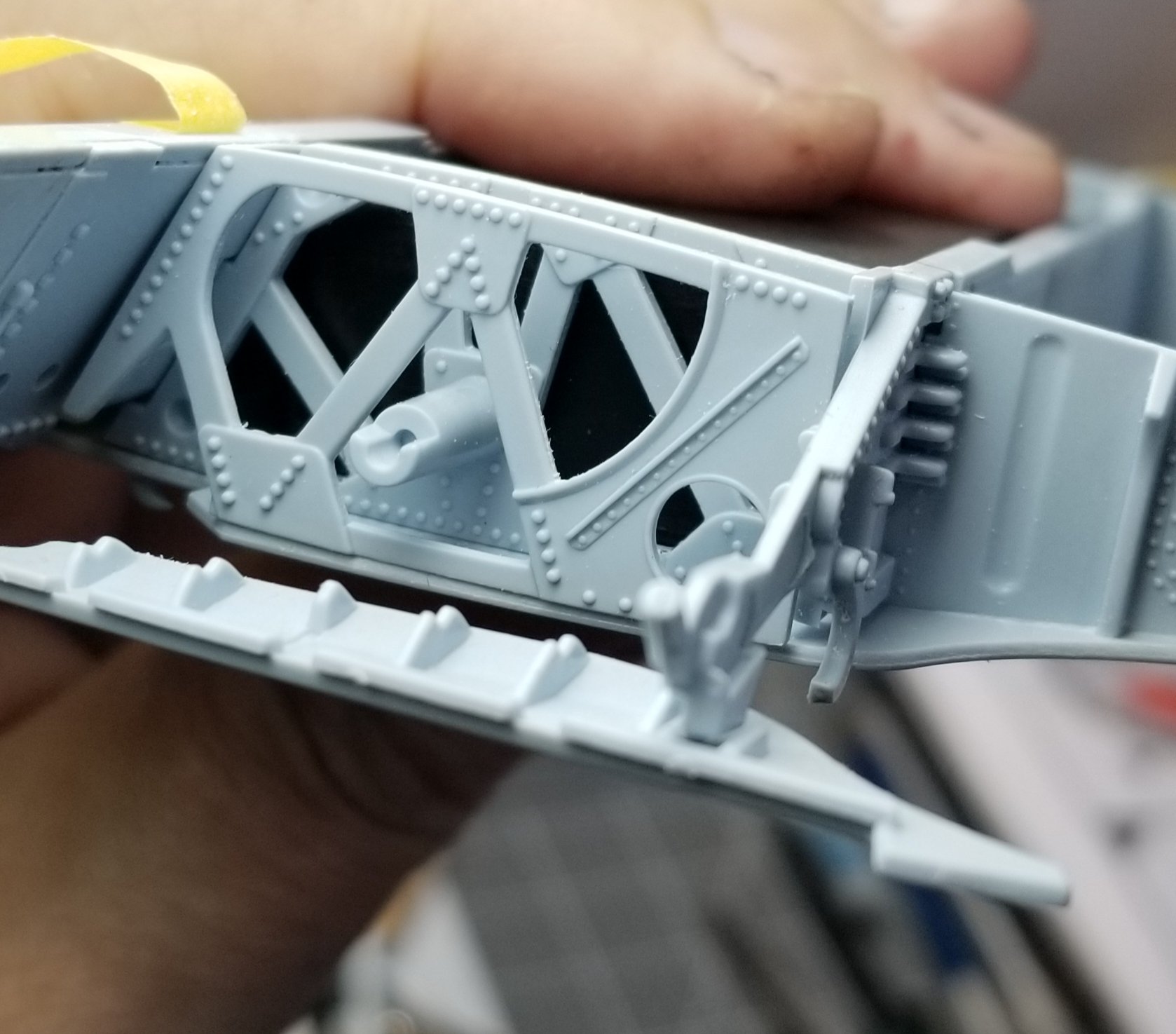
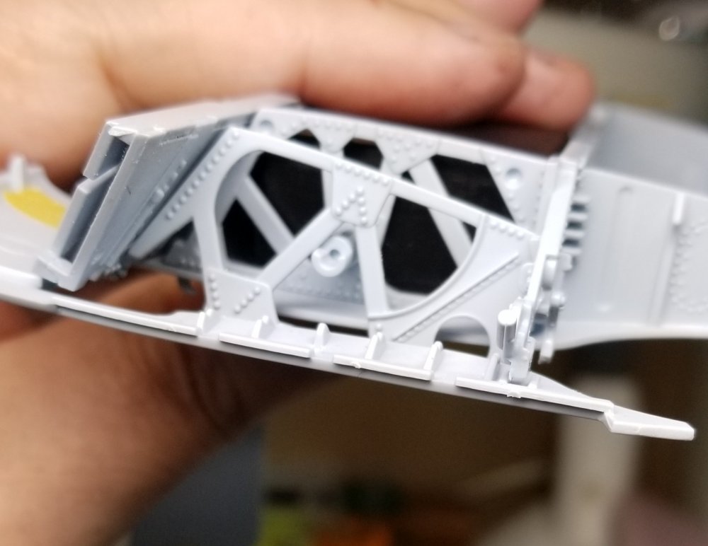
Well here goes. This is a pretty impressive model as has been stated before in reviews of this kit you have to follow the instructions to make sure you're building it the way you want, that is in flight. On the ground wings deployed or on the ground wings folded. Ok lets start. I'm going to jump ahead a little to show the fuel tanks I'm making so when you look through the wing structure you can see them instead of a big void. Here are some pictures. this tells sbout the fuel tanks on the Hellcat. this is the center section temporarily put together this is the center section with the port fuel tank that I scratch built out of .04" plastic card. this is the fuel tank by its self. this is looking through the wing structure. another view through the wing. another view. Thanks for looking Ron G


- 57 replies
-
- 10
-

-
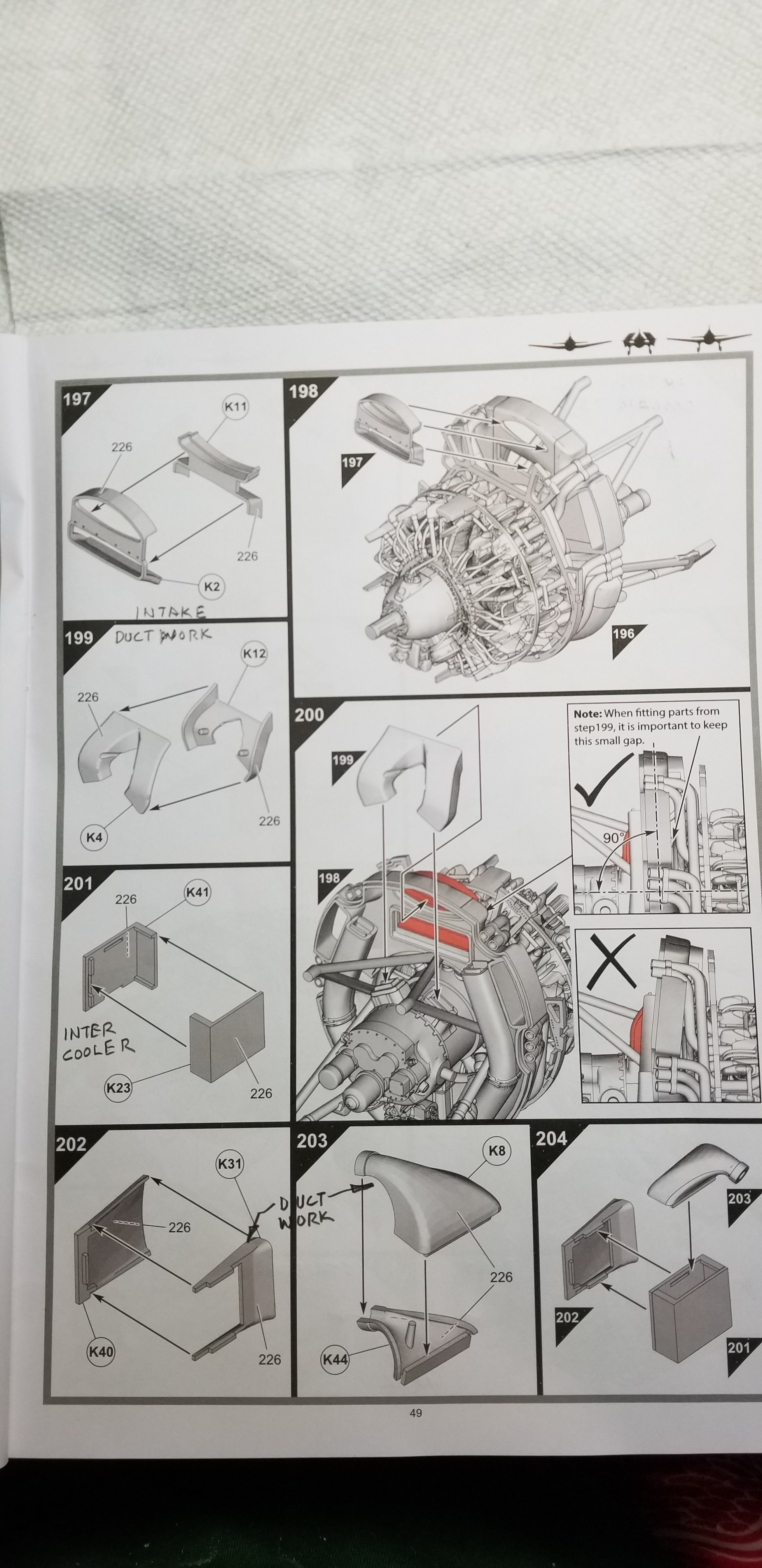
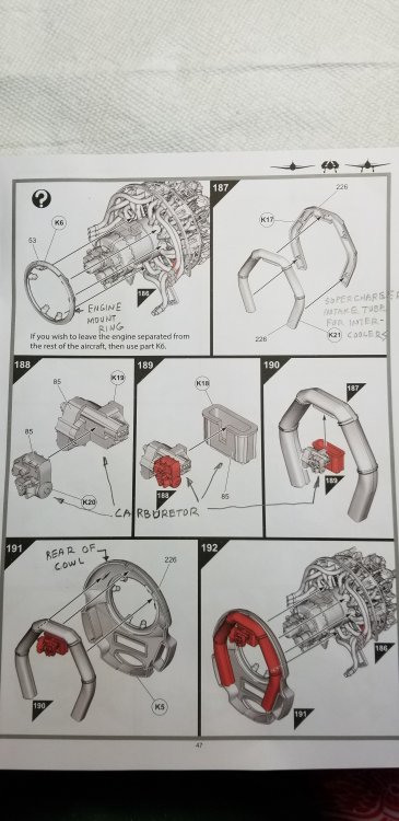
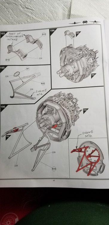
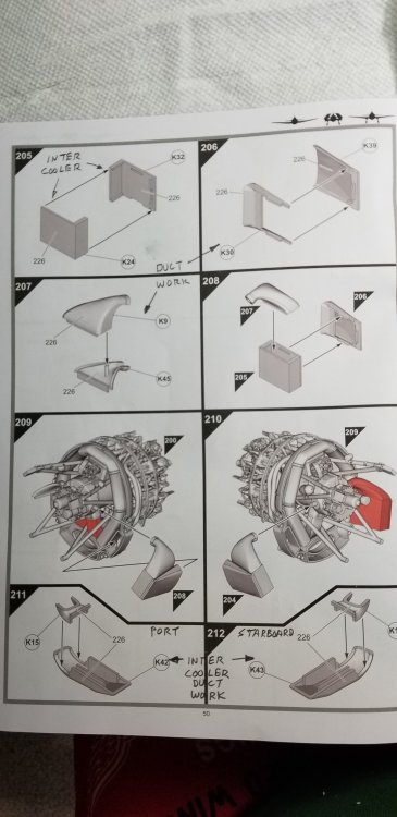
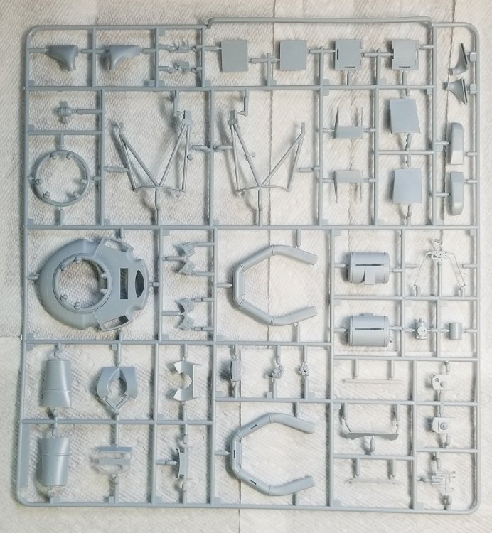
We continue on. this page shows K6 DON'T USE THIS PART!!! this is only if your not going to put the engine on the plane. It also shows K17 & K21 this is the duct work that attaches the carburetor to the inter-coolers. It also shows parts K18, K19 and K20 which makes up the Bendix PT-13 carburetor. It also shows how these parts attach to the rear cowl part K8. this page shows K13 & K14 which make up part of the supercharger housing. [NOTE] After investigating how all of these parts go together I have found out that these should be put on in <SEC. 152> on page 39. This is so you can add filler as needed in the gaps between these and the crankcase assembly and be able to smooth out the joint before you paint them. This page also shows parts K10 & K22 the engine mounting structure tubes along with part K7 which is an accumulating tank. this page shows part K2 & K11 that makes up into a air intake duct for the supercharger and oil cooler (supercharger upper hole oil cooler lower hole. Parts K4 & K12 make a intake duct for the supercharger. Then <SECS. 201 - 204> made of parts K8, K23, K40, K41 and K44 make up the port intercooler. On this page are <SECS. 205 - 208> made of parts K9, K24,K30,K32,K39 and K45 make up the starboard intercooler. <SECS. 209 & 210 show how to mount the intercoolers to the supercharger housing. Parts K15 & K42 make up the port connecting duct from the port intercooler to the carburetor duct. Parts K16 & K43 make up the starboard connecting duct from the starboard intercooler to the carburetor duct. WOW!...These things are more complicated then plumbing a turbocharged Promod...lol. I'll finish this off with pages 51, 52 and 53.see you in a bit. Ron G

-
Sorry guys I forgot to say I'm looking for them in 1/24 scale...opps
-
That sounds very interesting Jeff now if I can just get Airfix to sell me just the engine sprues that maybe a possiblity...lol Ron G
-
What to do, what to do...HELP!
CrankyCrafstman replied to CrankyCrafstman's topic in Modelling Discussion
I'll try that on her, but I will hold on to the family jewels will I do...lol -
Hey all Does anyone make WW2 US & British bomb stencils? Ron G
-
Hey Jeff By all means tag along. When I say it is the most accurate I mean it has almost everything included on the kit engine. There are a few things missing, but thats what modeling is all about. The molding to me seems pretty crisp, you need to be careful removing parts from the sprues so you don't cut of something that is supposed to be there. There are linkages missing but those are almost impossible to create by molded plastic. Now this is only one version of this motor and I'm pretty sure it was only in the Hellcat and Black widow. The P-47's, Corsairs were different variants. Ron G
-
Thanks Sapper If you have any questions please feel free to ask. I will try to answer them to the best of my ability. Ron G
-
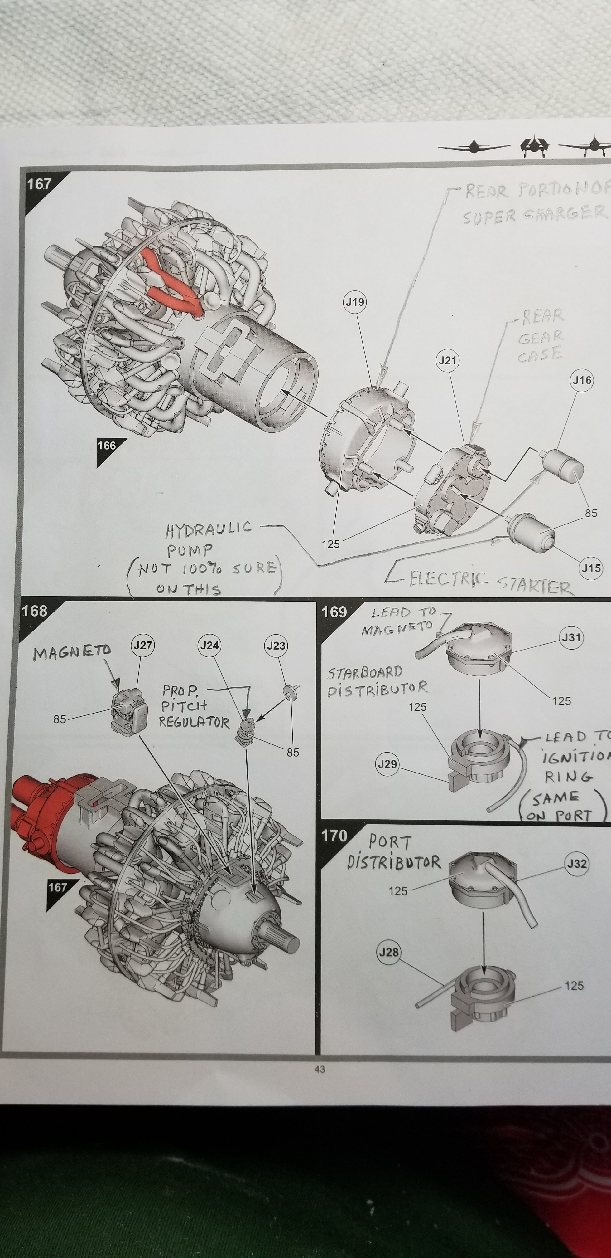
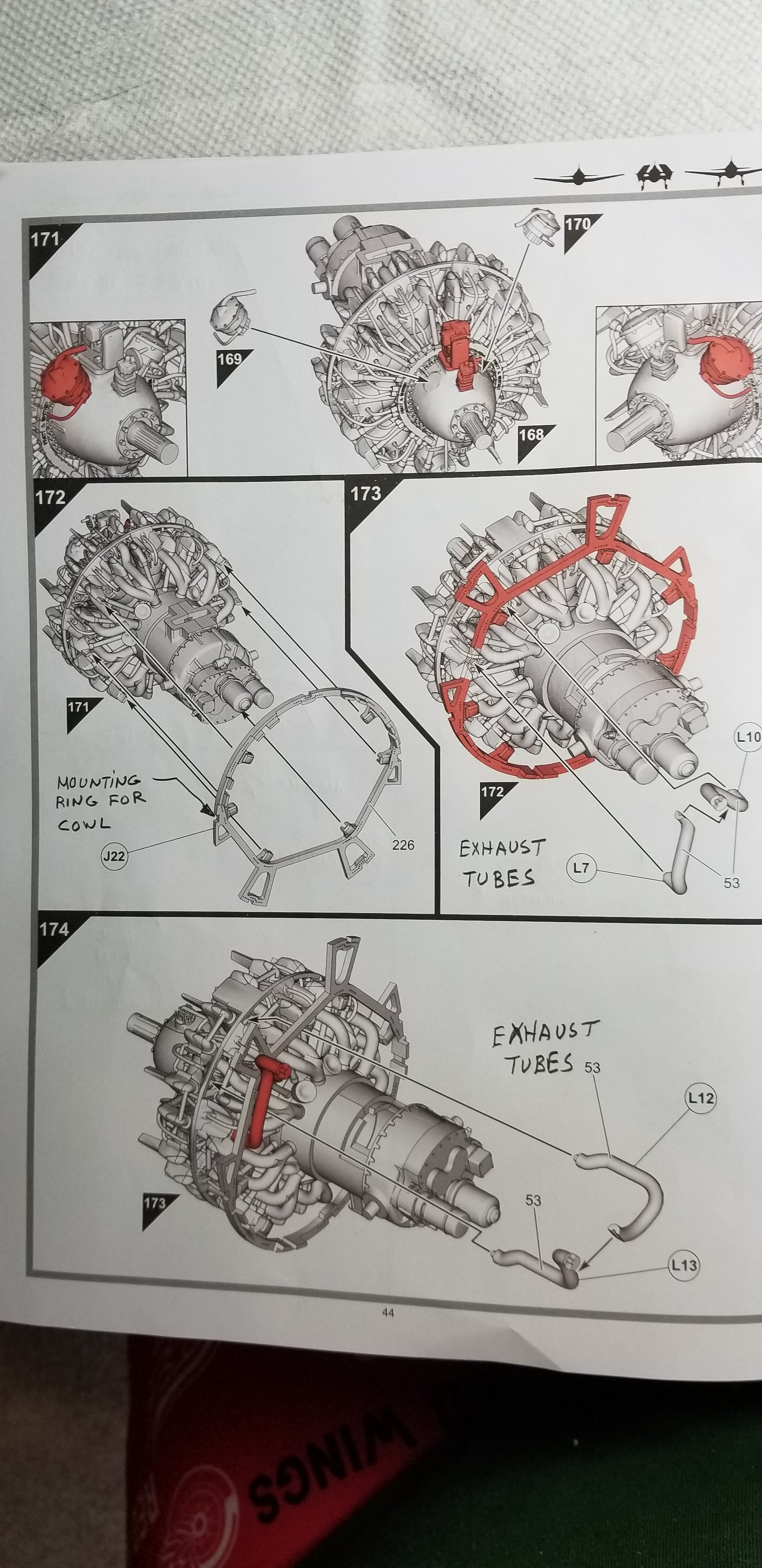
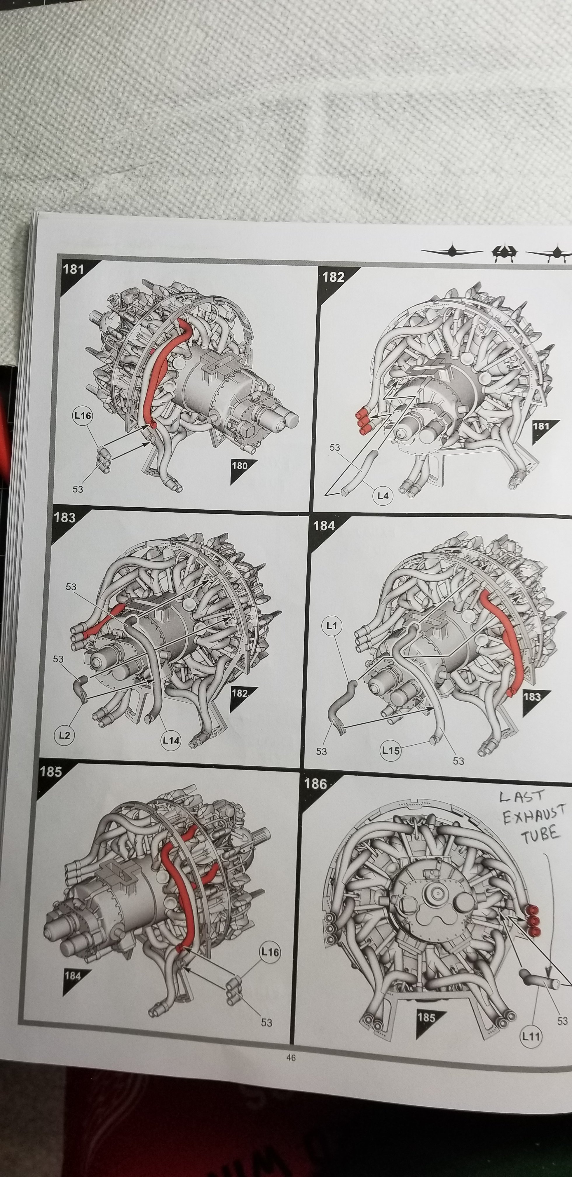
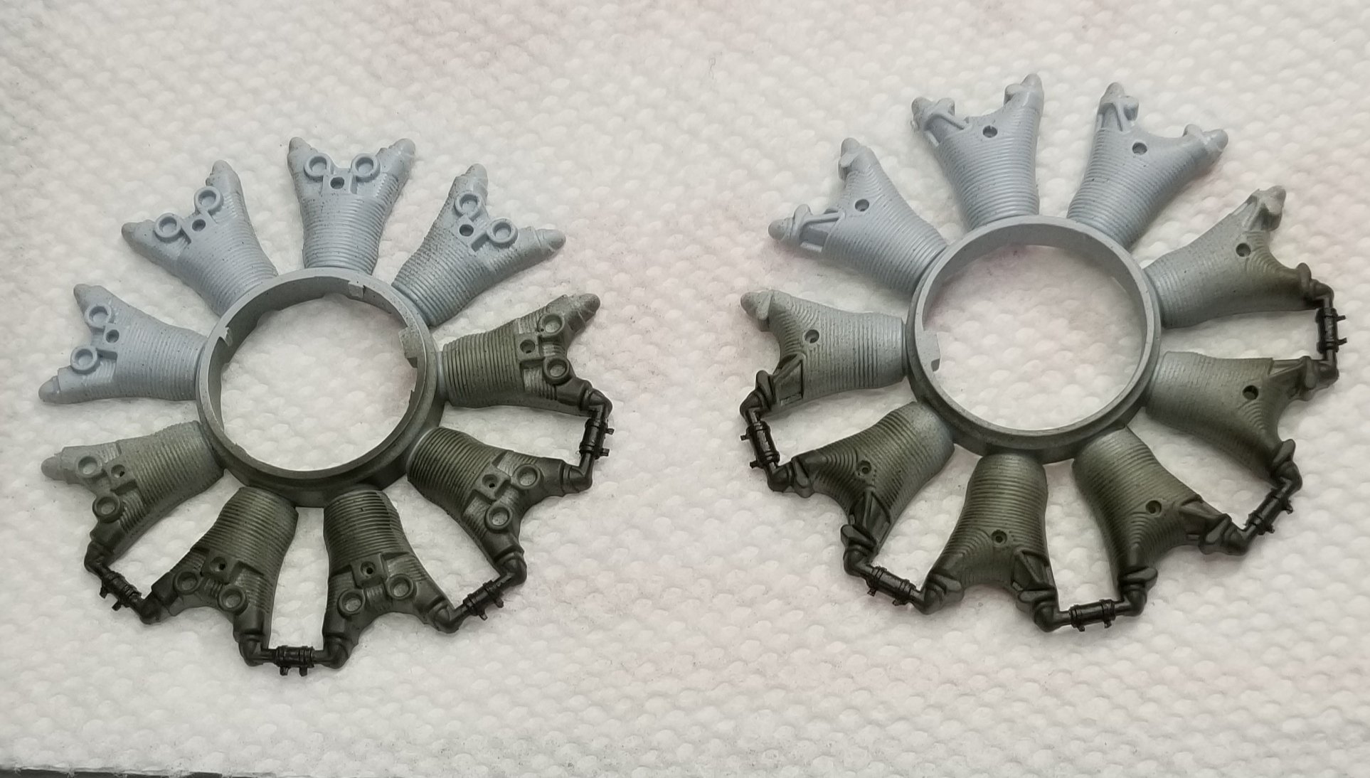
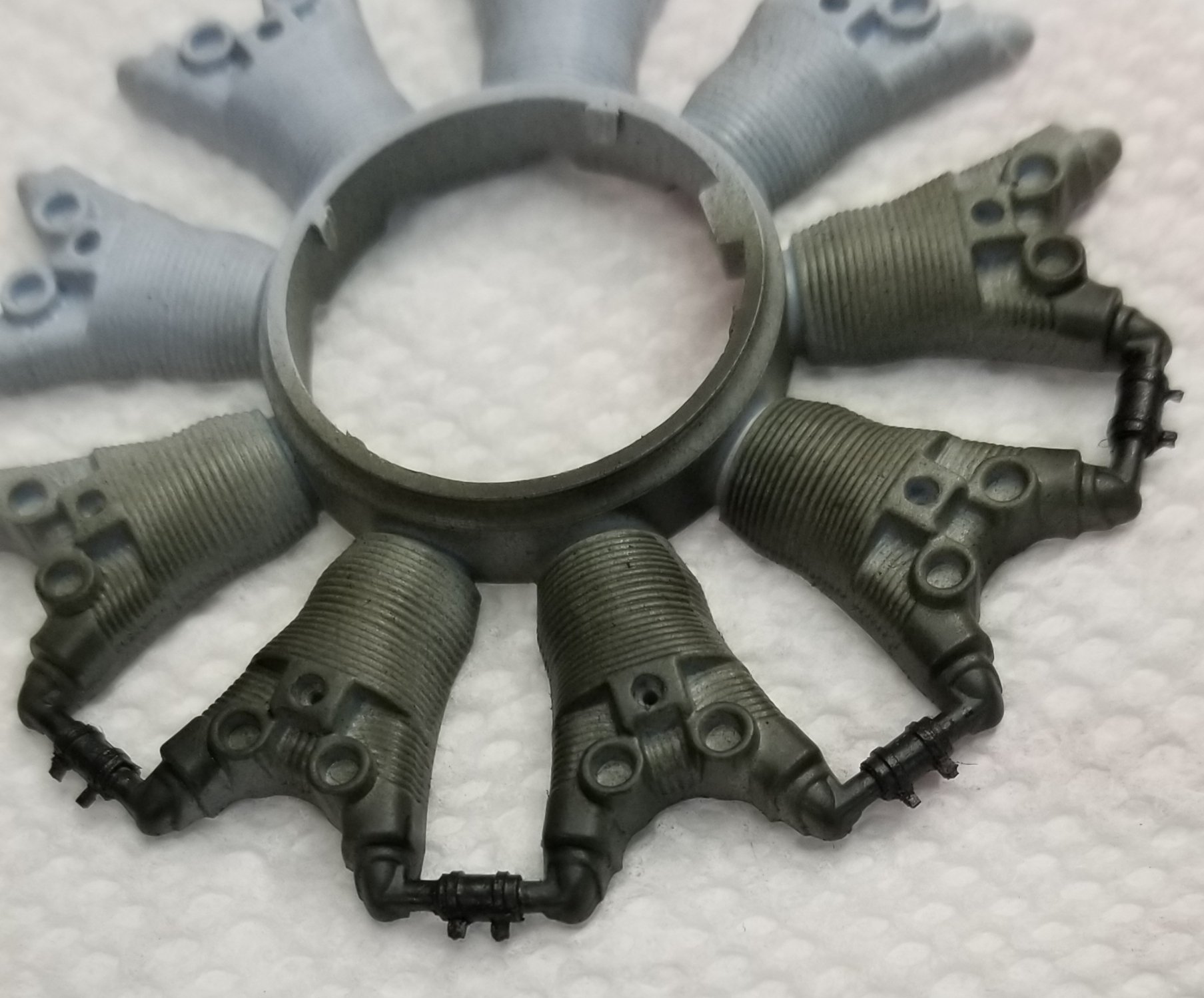
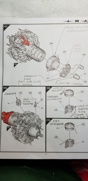
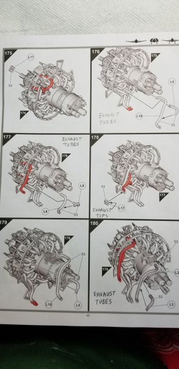
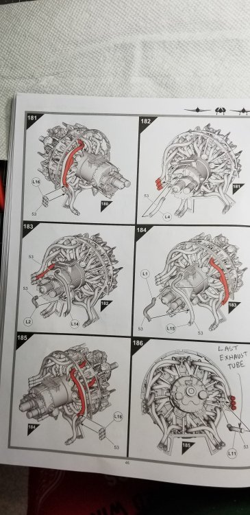
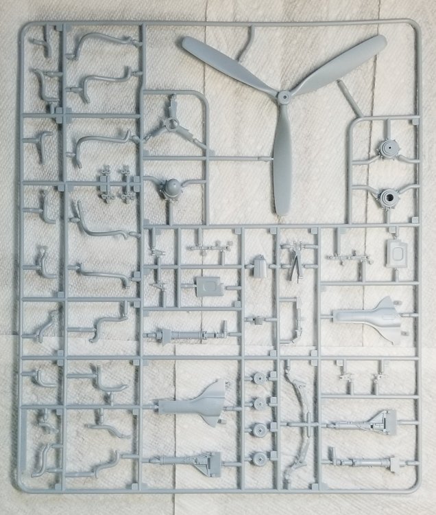
Ok here we go again. These next four pages cover the rear of the engine. this page shows part J19, J21, J15 and J16. Part J19 is the rear half of the supercharger housing and part J21 is the rear gear case. Part J15 is the electric starter and J16 is the hydraulic pump, this would be for the landing gear mostly. I'm not 100% sure that this is the hydraulic pump it could be a generator. This page also shows the Bendix-scintilla magneto and the port and starboard Scintilla distributors. You can see from my photo there are leads from the distributors to the magneto. These should be woven cloth covered like the ignition leads. They are about twice the size in 1/24 scale that would be 0.035"/0.045" diameter I plan on replacing these with braided wire like I'm going to use on the ignition leads. The ones that go from the distributor to the ignition ring my be ok I have to see when I get to that part. this page shows the rear cowl ring and inter-cooler mounts. It also shows the exhaust pipes being put on. this page shows more of the exhaust pipes being mounted along with the exhaust end pieces. this page shows the last of the exhaust being added with the remaining end pieces. Ok soak this in and I'll be back with page 47 and more. Ron G

-
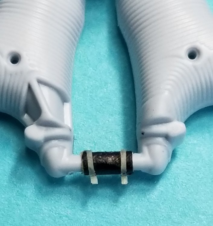
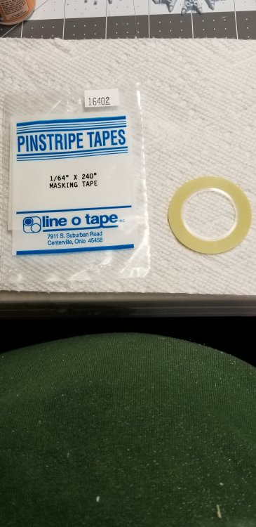
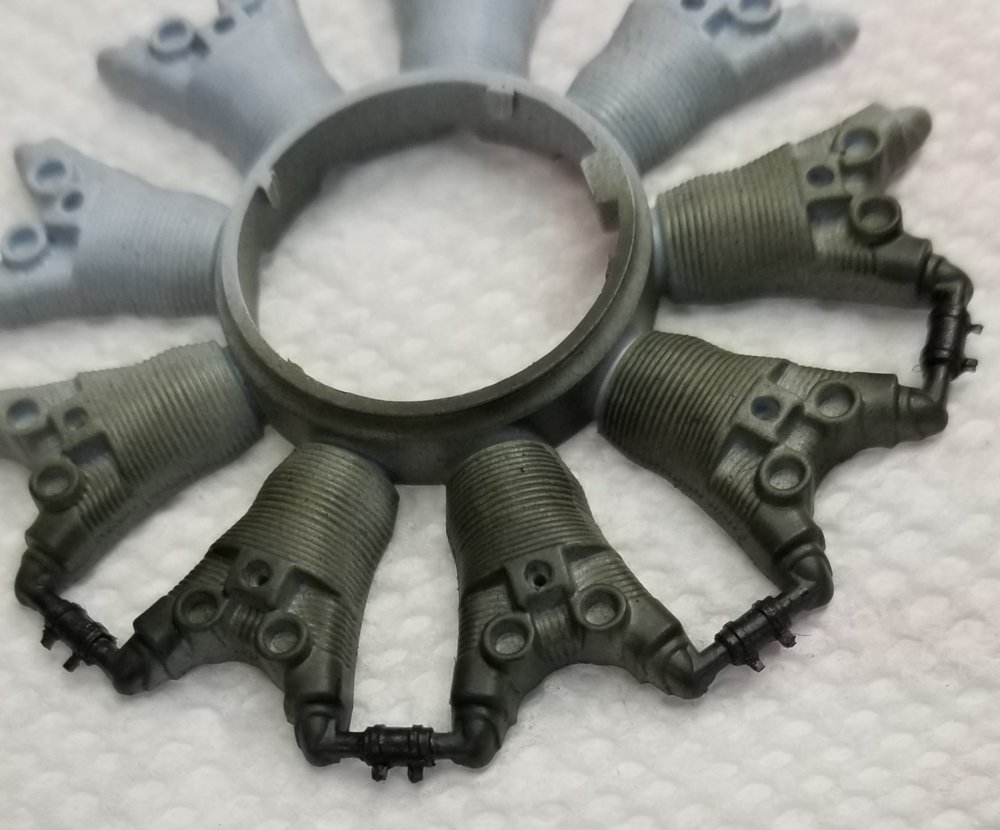
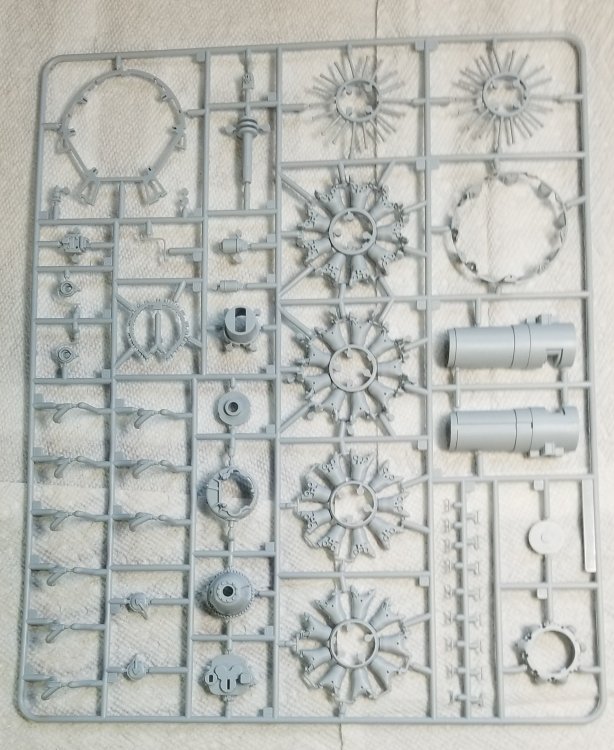
Hey all I decide to split this into two parts one on information on the actual engine and this one on the actual build. First this is the most accurately done model of this engine in any scale. This is my perspective, but I think I'm right. Its way better than Trumpeters 1/32 Hellcat engines even better than Tamiyas Corsair P&W R-2800 (Corsairs did have a different variant of this engine) and better then the 1/32 versions done in resins. Ok let's get started. First parts # J3 & J4 with J5 are WAY TO BIG!!!, that is the diameter of the area that the remaining engine parts go over is to TO LARGE. You will need to sand approximately 1/2mm to 3/4mm off of the area were the parts J8,J9,J12,J10,J11 and J20 fit you also need to remove material from inside the inner diameters of those parts in order to get them to fit. Sand carefully and test fit often. It's a lot of work but it will make up into a fantastic model. Rember you also need to do all the clean up to all of these parts that you would normally have to do. If you go to YouTube and watch Nigels builds he ex3it very good. His 5th video on the FAA one shows him removing material from the crankcase with his lathe. Good stuff. If you will notice on part J11 there are 4 tubes that are molded onto this part that go from one cylinder head to the next. Airfix represented these as a basic tube, when in actuality they have a rubber sleeve in the middle of each one and hose clamps on each end of the rubber tube. You can represent these with some Tamiya tape cut to 3 1/2 mm or 1/8" (0.125") and then wrap them around the tube 3 times. Then on the ends of the rubber tube just in form the end wrap some 1/64" pinstripe tape to represent the hose clamps. The rubber tube should be painted matte black and the clamps should be painted silver. If you don't want to go this far you can just paint a 1/8" stripe matte black around the existing tubes on part J11. This is how I'm doing mine. I will eventually paint these matte black and silver. this is the small pinstripe tape that I used. I got this of of Ebay. here are the parts painted with Vallejo tire black to simulate rubber. close up view.

-
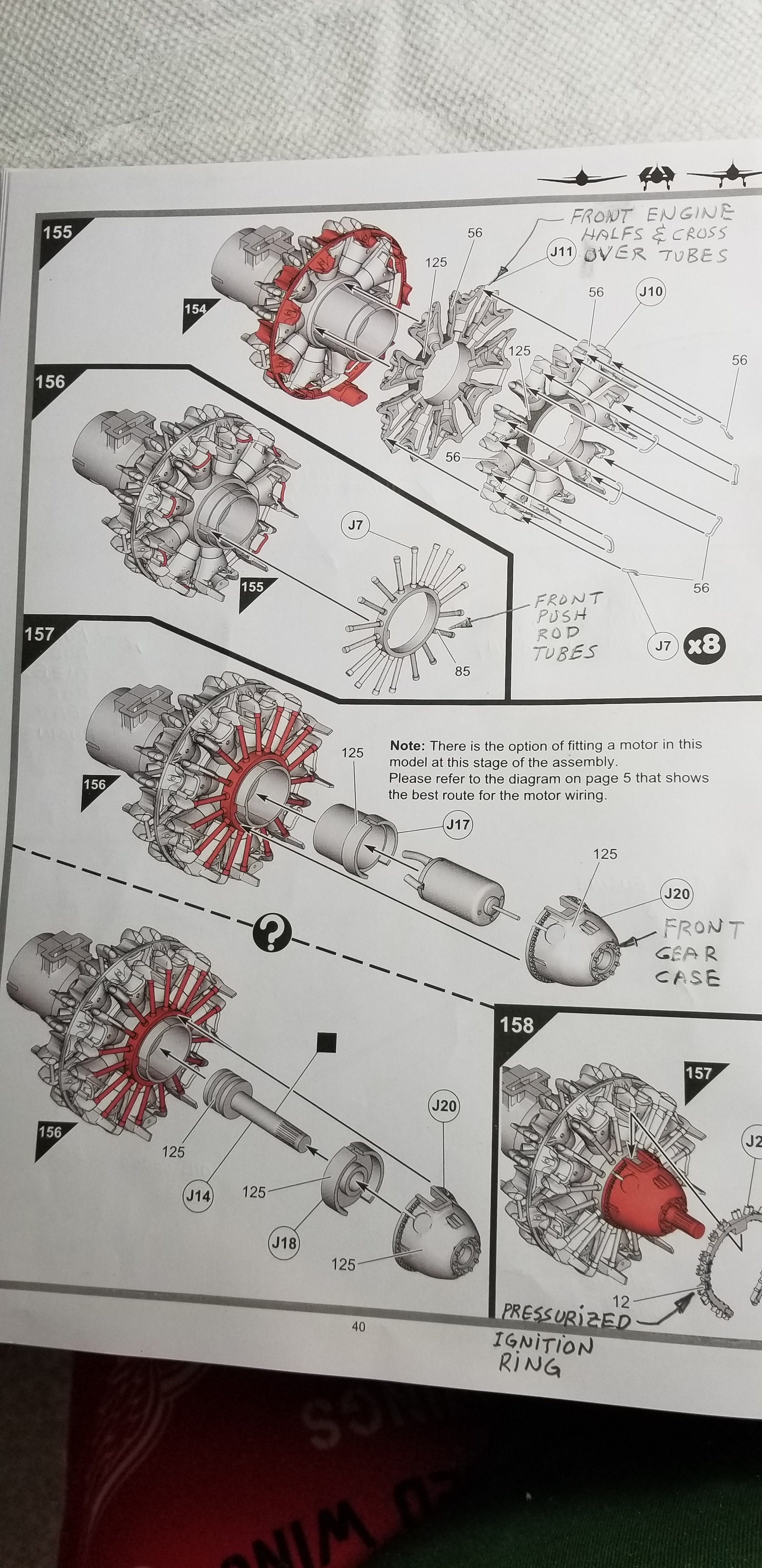
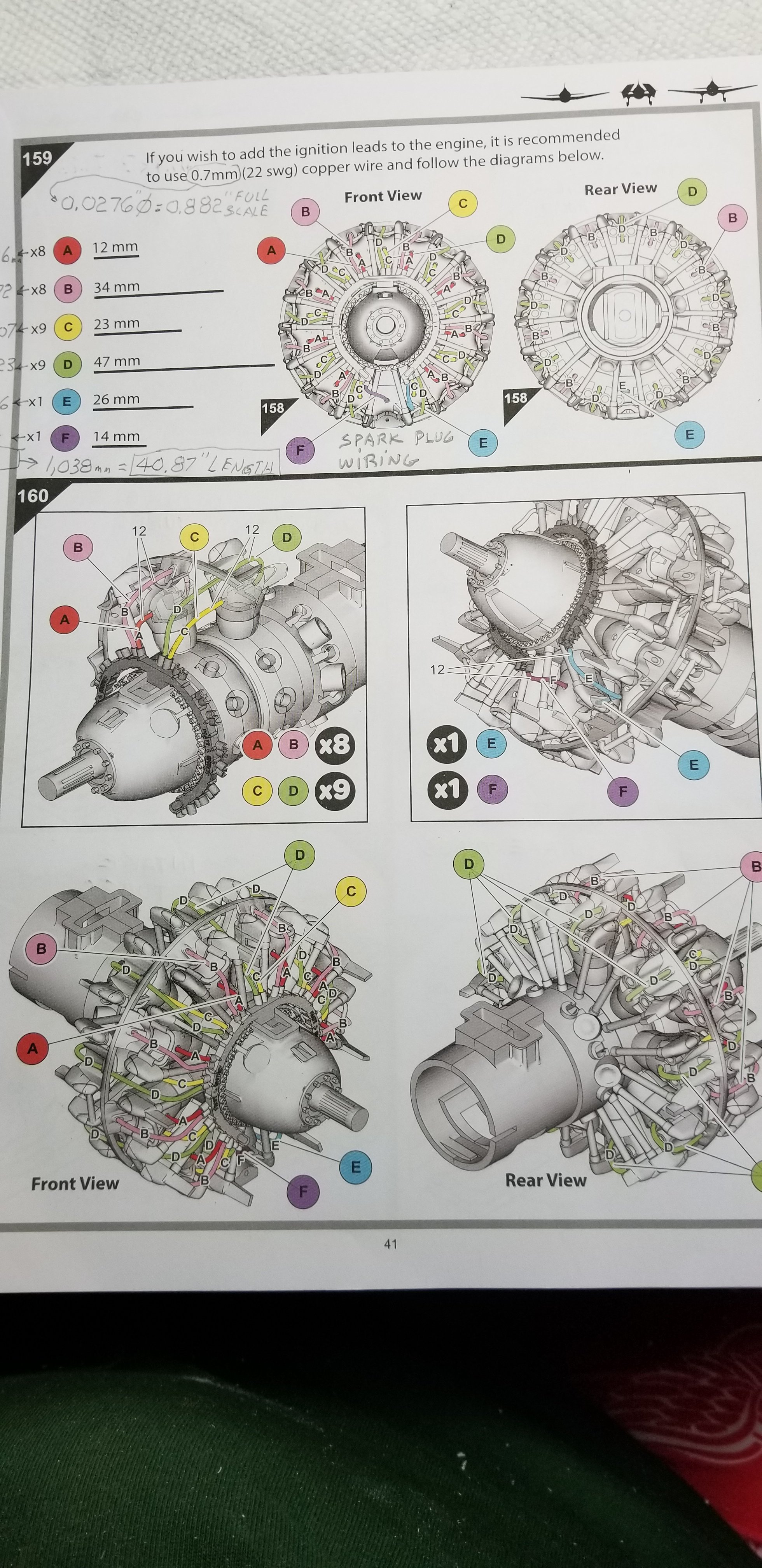
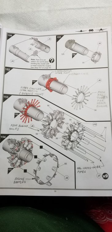
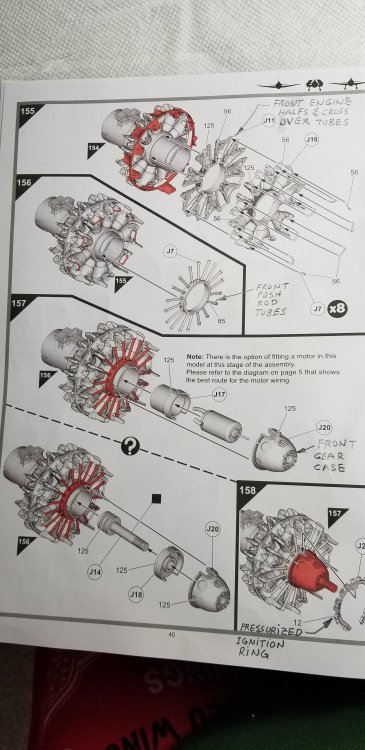
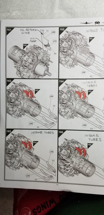
Hey all Ok here goes, this is going to be an informative post for all those who want to understand the intricacies of the Pratt & Whitney radial engine. My reason for doing this is after watching and reading many how tos on how to do the P&W R-2800-10 or R-2800-10W I've noticed that most people don't know what all the different parts are on this amazing engine. I'm not trying to put anyone down, far from it. I just want to put out some knowledge that I have accumulated over thirty some years in the automotive & aircraft engineering field. For those that don't know the radial is a basic internal combustion engine. It has a piston with a connecting rod incased in a cylinder. It has a intake valve and an exhaust valve with springs these are operated by rocker arms incased in the cylinder head and operated by push rods in tubes. This setup is very similar to a Harley Davidson motor. In the case of the P&W R-2800-10 or 10W there are 18 of these. I also want to show the correct way to paint this engine to make your models look that much more accurate and improve your modeling skills. I'm going to start by showing the kit instructions that I've marked up with the correct (as far as I've been able to discern) names for all the parts in the kit that correspond with the real thing. So here is the first picture. OH!...and by the way don't follow the instruction manual for painting this its totally wrong. this page shows J3, J4 &J5 which make up the crankcase and front supercharger section that contains the mounting surface for the Bendux PT-13 carburetor. It also shows part J6 which is the part of the engine crankcase that the intake tubes from the cylinder heads mount to, also it is the mounting area connection to the engine mount structure. [NOTE] Go to the third installment of this post for what to do about Parts K13 &K14 It also shows part J8 which is the rear engine push rod tubes. It shows parts J9 & J12 which are the rear engine halfs with the oil cross-over tubes. Finally it shows part J2 which is the baffle ring with the engine cooling baffles and a small oil collection tank. The kit doesn't contain all the cooling baffles. If you research you can find out what they look like and decide whether or not you want to scratch build your own. this page shows parts J10 & J11 the front engine halfs with the oil cross-over tubes. It shows part J7 the front push rod tubes. It shows part J20 the front gear case. This case contains all the gears for the distributor, front oil pump and propeller reduction gearing. It also has the front push rod tubes part J7 and the pressurized ignition ring part J25. This part is missing some mounting braces on each side that attach it to the part J20. If you look at pictures of this engine on the internet you can see what I'm talking about, I'll cover this later when I get to the actual build. this page shows how to create all the ignition leads (spark plug wires) from 0.7mm dia. or 0.0276" dia. Wire. The actual wires back in the 1940's were covered in a woven cloth. The best way to represent this is to use braided line, the kind that modelers use on automotive models. Detail Masters makes some #DM 1301 0.020" dia. You will need two packs to get enough to do all the wires. this page shows part J13 which contains part of the front gear case and the front oil pump. It also shows part J26 an oil line that goes from the small collection tank that is part of J2, the baffle ring, to the oil pump J13. The rest of this page contains parts J30 which are the intake tubes from the cylinder heads to the supercharger housing part J6. Thats it for know I'll pickup with page 43 next. Ron G

-
What to do, what to do...HELP!
CrankyCrafstman replied to CrankyCrafstman's topic in Modelling Discussion
Ok, now I just have to figure out how to talk the other half into letting me get the Typhoon...lol -
What to do, what to do...HELP!
CrankyCrafstman replied to CrankyCrafstman's topic in Modelling Discussion
If you look back at my previous post I already got the Mosquito. Ron G -
Just a heads up for everyone, the painting instructions in the Airfix kit are not correct for the hellcat. First the cockpit was interior green (FS 34151) over zink chromate yellow excluding the instrument panel and side panel parts that are black, the -5 (which is what this kit is) was interior green up to the bottom of the instrument panel and was matte black from there up. Next the cowl area was Grumman gray and the area from behind the cowl to the cockpit was interior green. The area from the back of the bulkhead that the seat is mounted on all the way back to the arresting hook area was also Grumman gray. The inside of the tail was interior green. The inside of the wings was done in zink chromate yellow and the belly area where the fuel tanks were was interior green. For the colors for the P&W R-2800-10W see my build for this part of the kit. I'm in the process of getting it ready as we speak. Thanks Ron G
-
Yes it does, you have to build it one way or the other. The wings do not actually fold. Hey Ernie the P&W R-2800-10 in this thing is the most accurate representation that I have ever seen. Look for my build of it for correct painting and detailing. Ron G
-
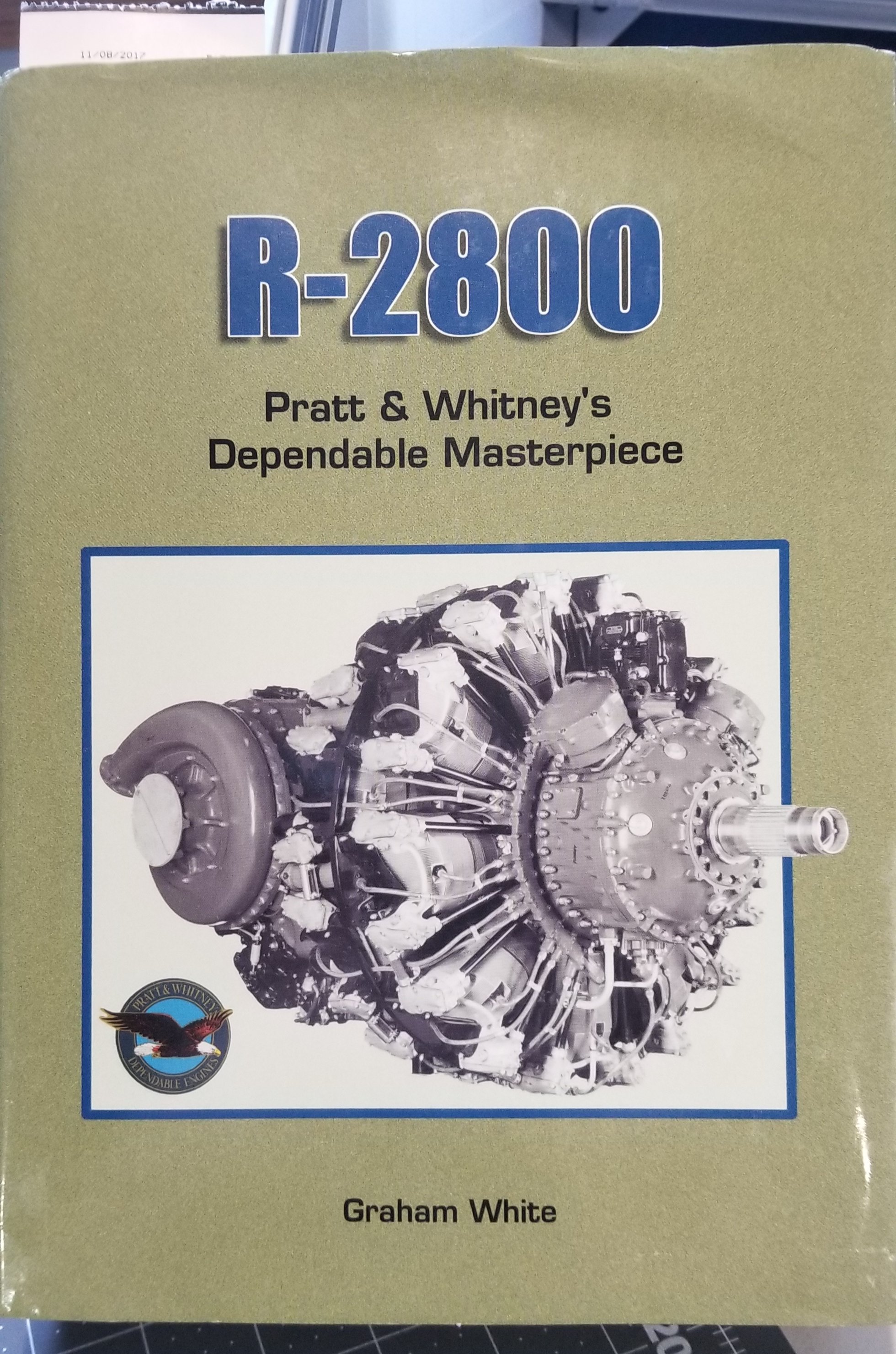
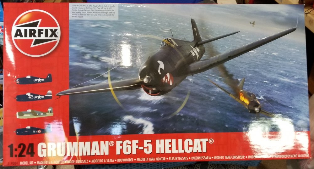
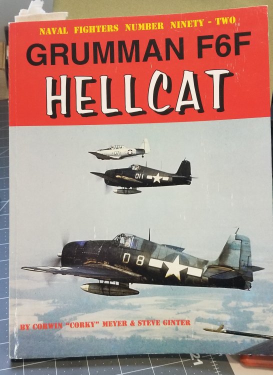
Well it finally got here Airfix 1/24 F6F-5 Hellcat. WOW this thing is ASSUME!!! This has the best and most accurate Pratt and Whitney R-2800-10 that has ever been modeled. I'm going to be doing mine as a F6F-3. I think I can do it there are three things that need to be done to create the -3 1) modify the front canopy, I have to ad some upper frame straps to it. I'll post pics when I get to that point. 2) add the bulge in the lower cowl just over the exhaust openings, you really don't have to do this, but it will make it more obvious that it is a -3. 3) add the windows to the fuselage just behind the pilots head rest. I also hve to add the little windows on either side of the head rest pad on the armor plate. Oh yeah I need to paint it in the tricolor paint scheme. I might do a build of the P & W R-2800-10 showing the proper why to paint one based on the book by Graham White "R-2800" pratt & whitney's dependable masterpiece. And a lot of reference photos I've accumulated over the years. Most people don't know how to paint it. Mostly because they don't understand how it works and what all the pipes, tubing and wiring are for. I plane on adding any wiring and linkages that are missing. I'm also going to add spark plugs with correct braided plug wires. Right know I'm investigating the parts and planning how I'm going to accomplish this. So for know here are some pictures. Ron G
-
What to do, what to do...HELP!
CrankyCrafstman replied to CrankyCrafstman's topic in Modelling Discussion
Yup they are very nice. Right now I'm more interested in the Yahu instrument panel for the Mossie. Ron G -
What to do, what to do...HELP!
CrankyCrafstman replied to CrankyCrafstman's topic in Modelling Discussion
Hey guys Ok I went for the Mossie. With the Master gun barrels. Now all I have to do is put a HUGE addition onto my condo to fit it in...lol RonG -
What to do, what to do...HELP!
CrankyCrafstman replied to CrankyCrafstman's topic in Modelling Discussion
My Hellcat arrives tomorrow. -
Hey all I need your guys input. I'm trying to choose between a 1/24 Airfix Mosquito for $175.00 US (these are selling fo close to $400.00 US on Ebay) or a 1/24 Airfix Typhoon 1b (bubble top) for $169.00 US. I'm kinda leaning towards the Mosquito, because it's been out of production for 9 to 10 years and they are getting scarce. The Typhoon on the other hand is also out of production although not for as long. I really like the Typhoon, looks so cool in full D day dress. I want to get both but can't afford to do both right away. So it has to be one or the other right now. I'll be able to get the other one in a year or so, but I'm having a hell of a damn time trying to figure out which one. So everyone chirp in and let me know what you think. Ron G
-
Nige does a great job on his videos. He's doing TWO! Hellcat builds on YouTube now. I'm waiting for my big cat to come in the mail so I can build along with him, although I plan on converting mine into a F6F-3. Ron G
-
Hey Clunky I don't know, haven't heard from him either. He's doing a build of the 1/24 Airfix f6f-5 on YouTube. Ron G
-
Hey all I haven't got it yet, but ordered the new Airfix f6f-5 hellcat. Hopefully it will be here in a week. I plan on building it along with Nige. I'll post pictures when it arrives. Ron G