CrankyCrafstman
-
Posts
1,358 -
Joined
-
Last visited
Content Type
Profiles
Forums
Events
Gallery
Everything posted by CrankyCrafstman
-

Trumpeter P-47D Razorback
CrankyCrafstman replied to crazypoet's topic in LSM 1/35 and Larger Work In Progress
I went through the P &W R-2800 book and did not see one photo or discription that said/showed they had tubes for spark plug leads. They had a pressurized ignition ring but not the plug wires. Plus they all didn't have pressurized ignition systems. Ron G -
Ok, thanks again Anthony
-
Thanks Anthony Actually I finished them Friday evening, before I got your photos, but thanks they helped to refine my plans. Hey did you ever find those Paragon exhaust shrouds? I could sure use em if you got em. This thing is a huge drain on ones modeling mojo, and I know you get what I mean.
-
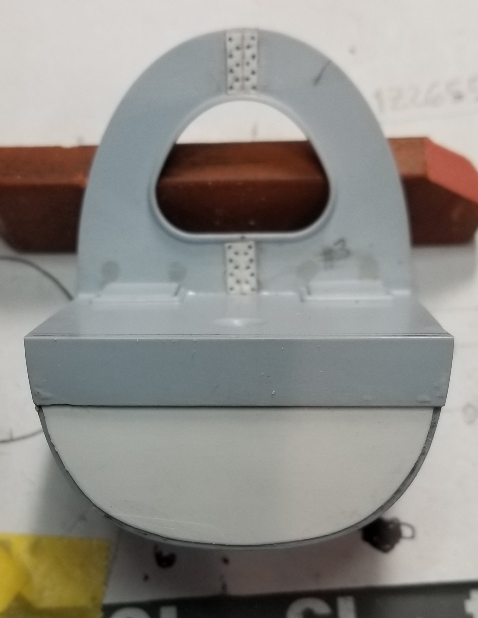
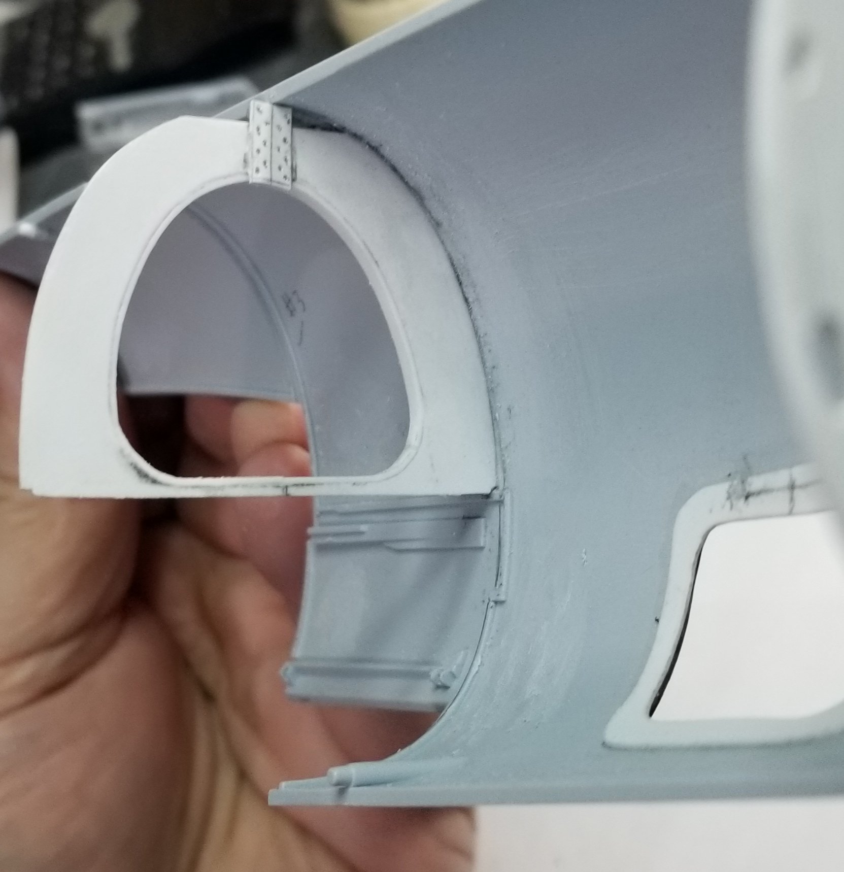
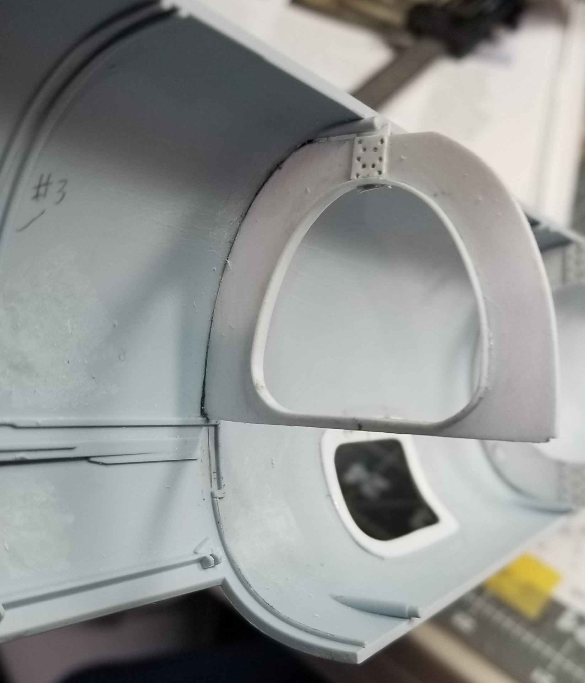
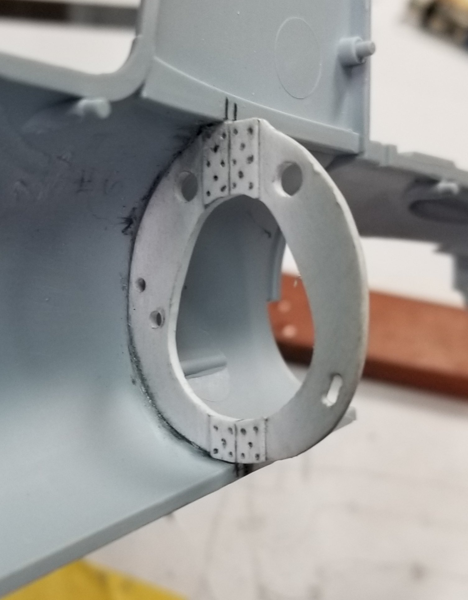
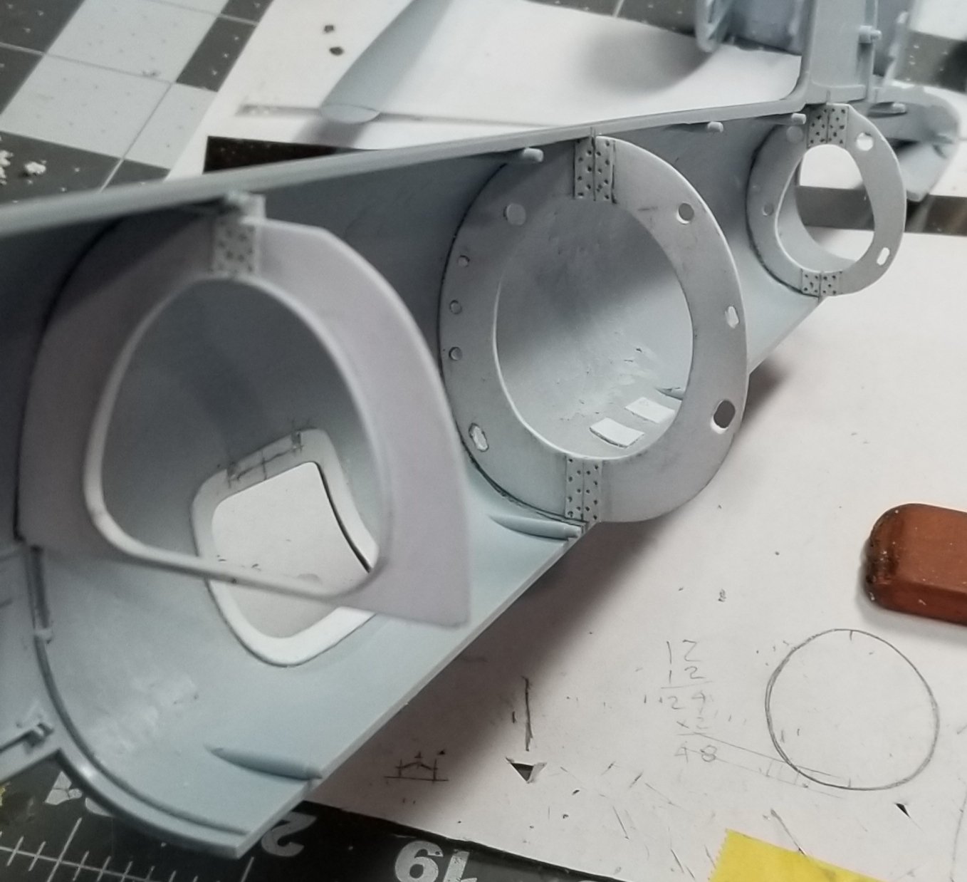
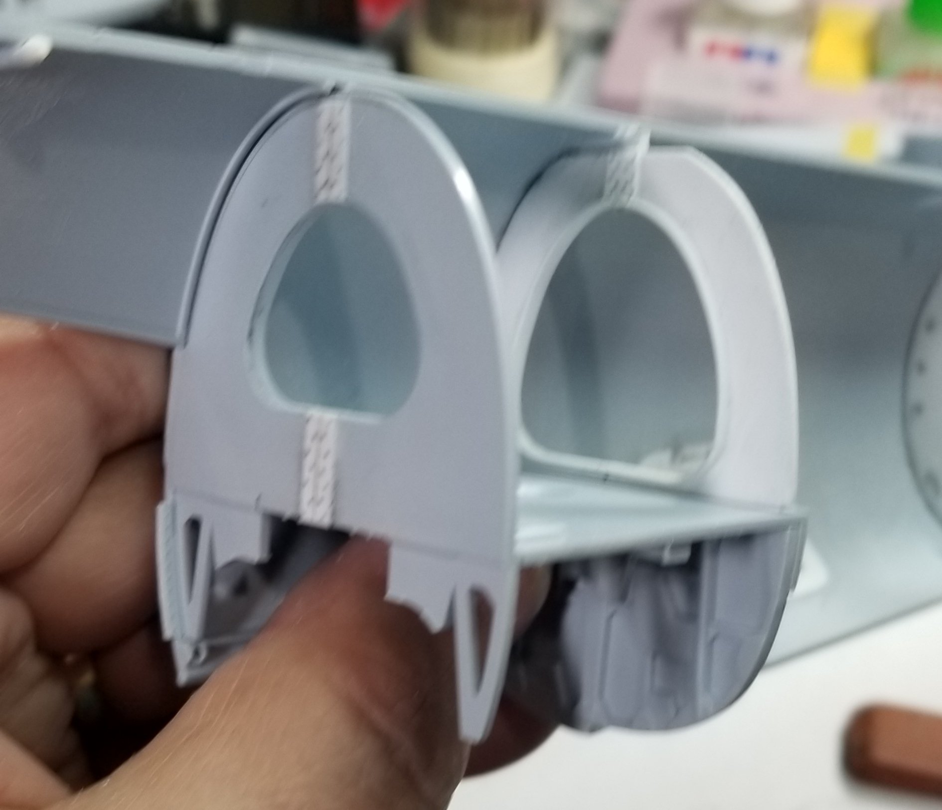
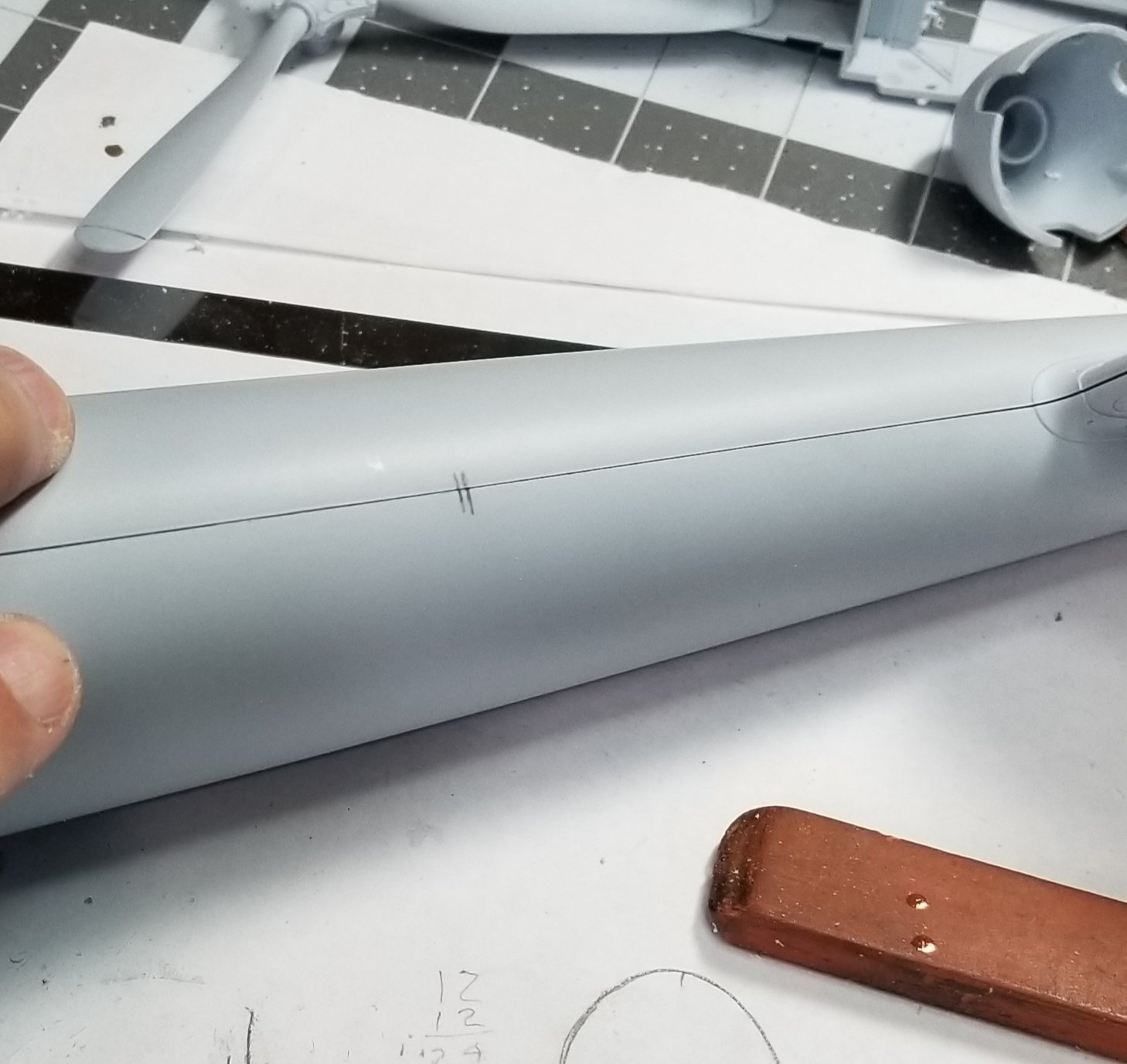
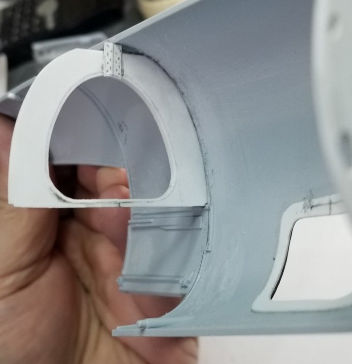
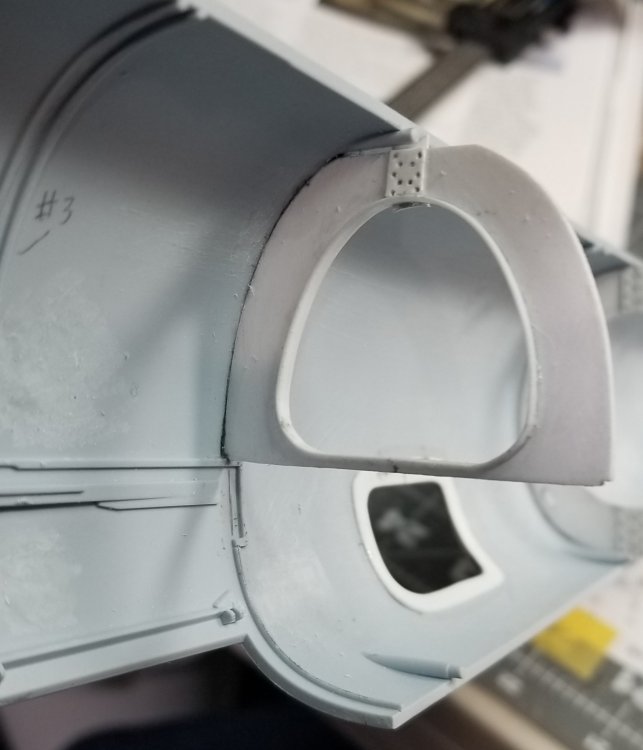
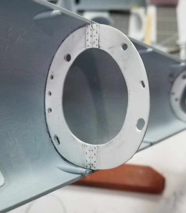
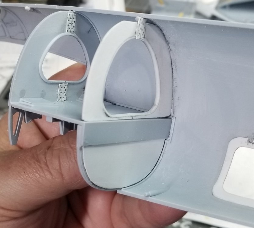
Some more progress on this beast. I decided to add all of the bulkheads from 1 through 7. Bulkhead 1 comes in the kit, 2 comes in the kit, 3 comes in the kit, 4 only has the lower half in the kit so I made the upper half of it. 5 is totally from scratch, 6 is totally from scratch and 7 comes in the kit. Here are some pictures. This is the rear of bulkhead 3 and lower portion of bulkhead 4. I added the two white peices of plastic card to represent the attachment plates that held the two halfs of the fuselage together. This is the front of bulkhead 3 and the added plates. This is bulkhead 4 upper, I added the plate and the inside of the cutout is lined with a piece of 0.015" thk. x 0.08" wide plastic card. Similar to what is on bulkhead 3. Front view of bulkhead 4 showing the added plate and card stock rib added to the cutout. This is bulkhead 5 with the added attachment plates. This is bulkhead 6 with the added attachment plates. This view shows bulkheads 4 upper, 5 and 6. this is a view looking forward at bulkheads 4 and 3. You can see how my part fits to the kit parts. I also added a piece of card to the lower half of the back of bulkhead 4. View looking rearward through bulkheads 3 and 4. View showing the top of the fuselage joint, not to bad of a fit. This view shows the fit of the lower fuselage. View looking into the rear radio hatch. A view looking down through the fuselage. This will all be covered up, but I will know that it's there. Thanks for looking let me know what you think. Ron G


-
Hey Charlie are you sure you want me to bang it on the ground? Ron G
-
Trumpeter P-47D Razorback
CrankyCrafstman replied to crazypoet's topic in LSM 1/35 and Larger Work In Progress
Looking good Crazy Ron G -
So, what's on your floor tonight?
CrankyCrafstman replied to [CAT]CplSlade's topic in General Discussion
ALOT of Golden Retriever hair!!! Have to remember to block entrance to hobby area. Ron G -
Yes I have Definitely thinking about those for the Mossie or the Typhoon. Ron G
-
Time for another CORSAIR! LOL
CrankyCrafstman replied to JohnB's topic in LSM 1/35 and Larger Work In Progress
Looking good as usual John Ron G -
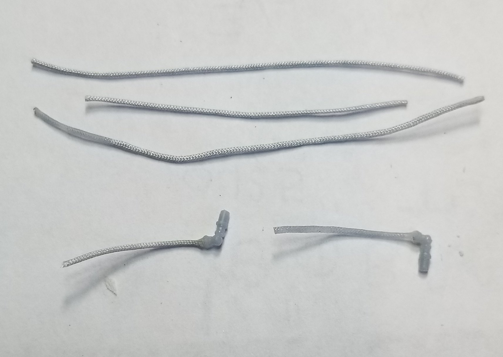
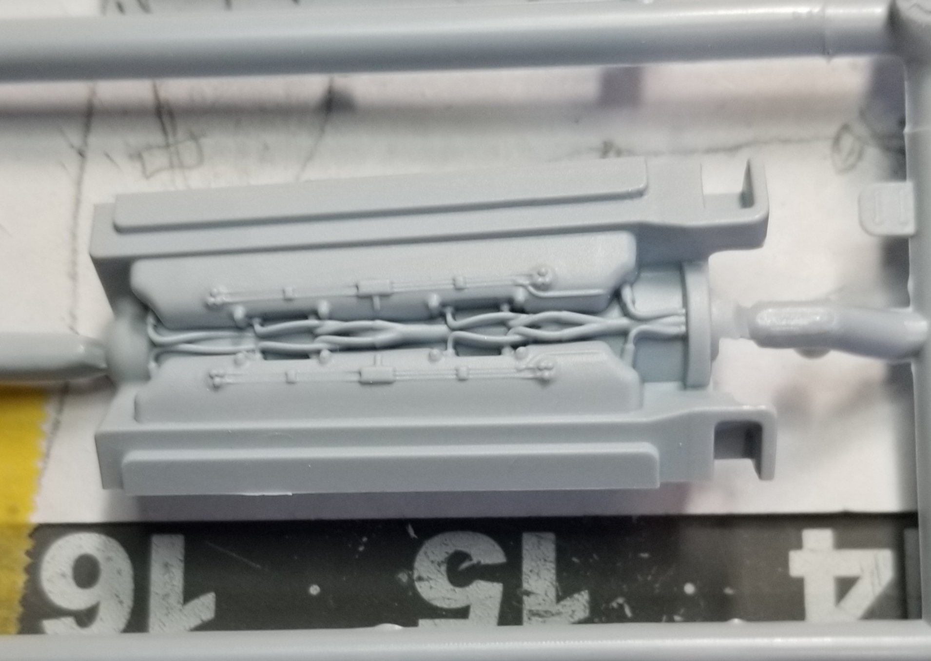
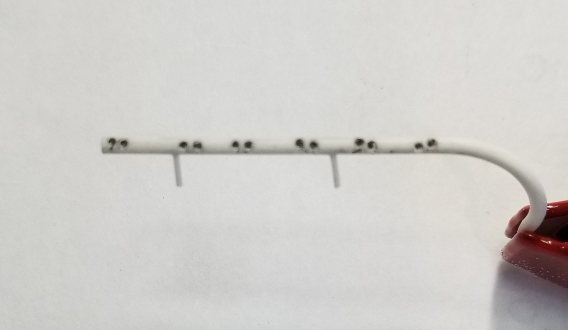
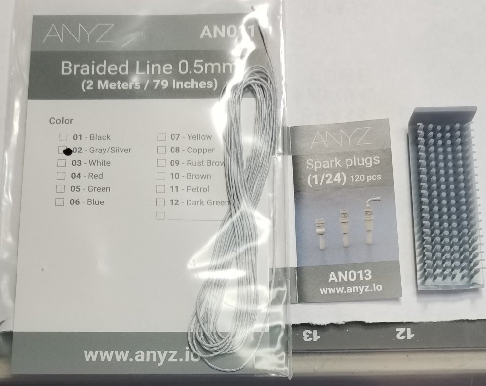
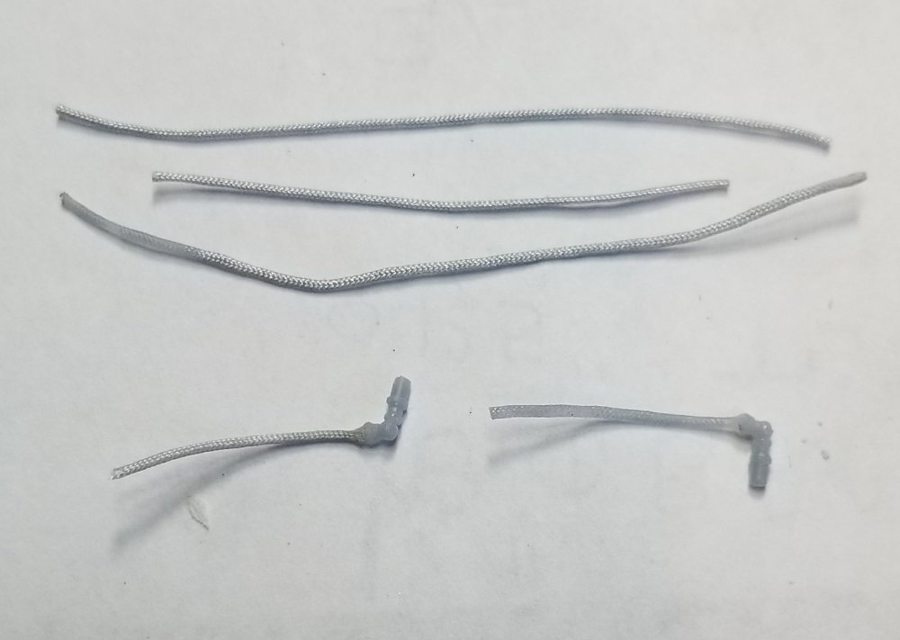
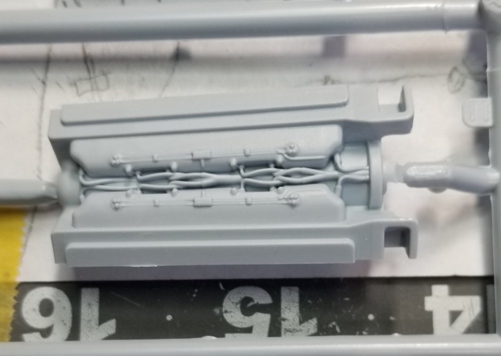
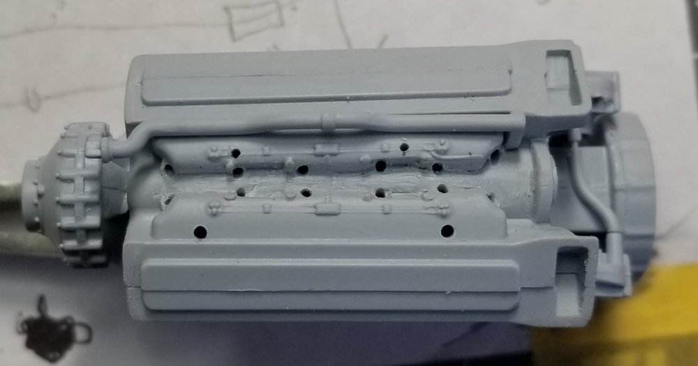
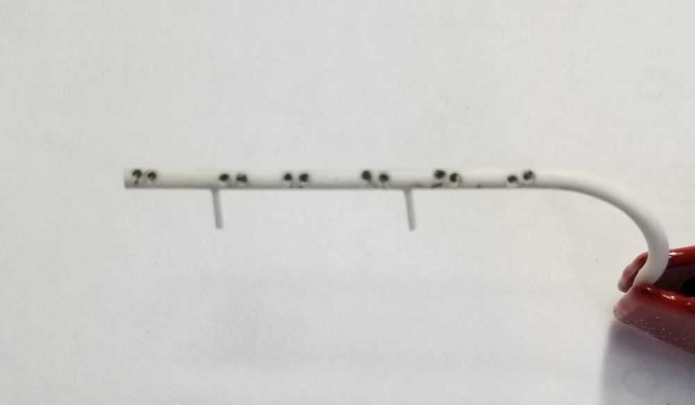
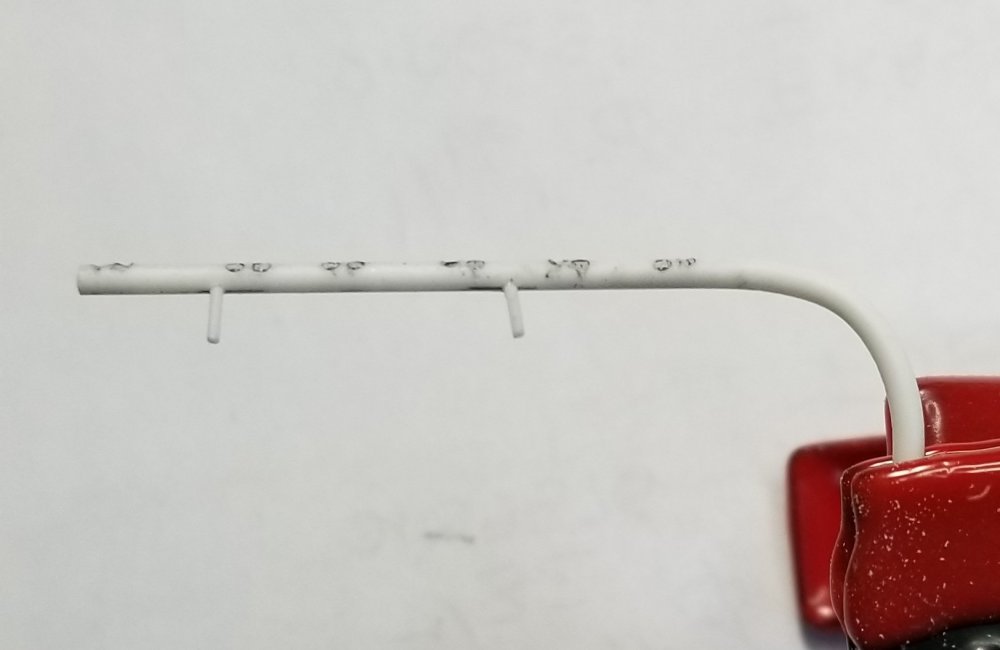
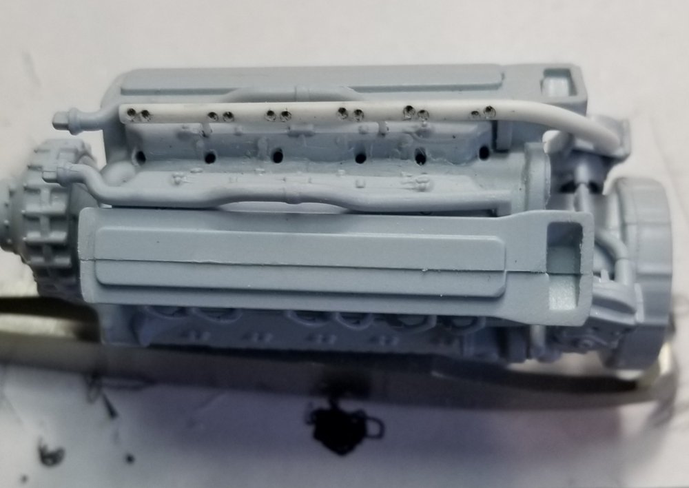
Hey all Ok I'm moving around on this build in order to keep my interest up, and not get burned out. I've started one of the engines. I figured out a way to be able to add the prop at the finish of the build, it will move, but not really spin, so it can be removed for transport. I forgot to take pictures of that, damn I'm getting old! I'm going to be adding the upper set of spark plug wires. I am using ANYZ Models super detailed spark plugs and wiring. These are from Thomas Anyz from Germany. First I had to remove the cast on ones, they are wrongly done anyway. I'm adding the pipe, made from some plastic rod, with the 12 plug wires and this will be attached to the right magneto (the right mag. fired the upper plugs and the left mag. fired the lower plugs on both sides.) This you can see on page 22, build step 81 by parts 7G right mag., 8G left mag. and 28G connecting pipe. Airfix almost got this right, they just forgot the pipe to the upper set of plug wires. 28G isn't connected to 7G correctly, but it's close, and it will be covered up by other parts so you won't really see it. Here are some pictures. Here's Toms stuff. Those spark plugs are really TINY! They are carpet monster magnets. Some wires and the two lower ones are made from two pieces and a wire. I'm using the grey/silver 0.05mm wire for these. This is the part 11G with the plug wires cast on This is my modified part, you can see 28G going from part 7G to part 8G at the rear in this photo. I removed the cast on wires and added the holes for the plug wires. I'm not going to use the spark plugs here (I don't have enough anyway) because they are actually buried so far down in the manifold you really can't see them. So just wires added to the holes and connected to the pipe. This is my scratch built plug wire pipe the end in the clamp goes to 7G right mag. the two small pins connect it to the intake manifold. Another view showing bend in pipe. This picture shows the pipe in place on the engine and connected to 7G. These are just temporarily put together, still have to paint the engine and all the small parts before I add the wires and sparkplugs. Very tedious work but will pay off in the end. So take a peak and let me know what you think. I hope I get this done before I crook...lol Ron G
-
Hey Doc I just started wiring my 1/24 mosquito engines with the ANYZ wires and sparkplugs. BOY are these things small and very fiddly. I did noticed that they do have a .4mm wire that would be perfect for 1/32 engines, not sure what colors are available, you would have to check his site for that. Ron G
-
Hey Doc I believe the anyz stuff is for 1/24 scale, the braided line is pretty big for 1/32 stuff. Ron G
-
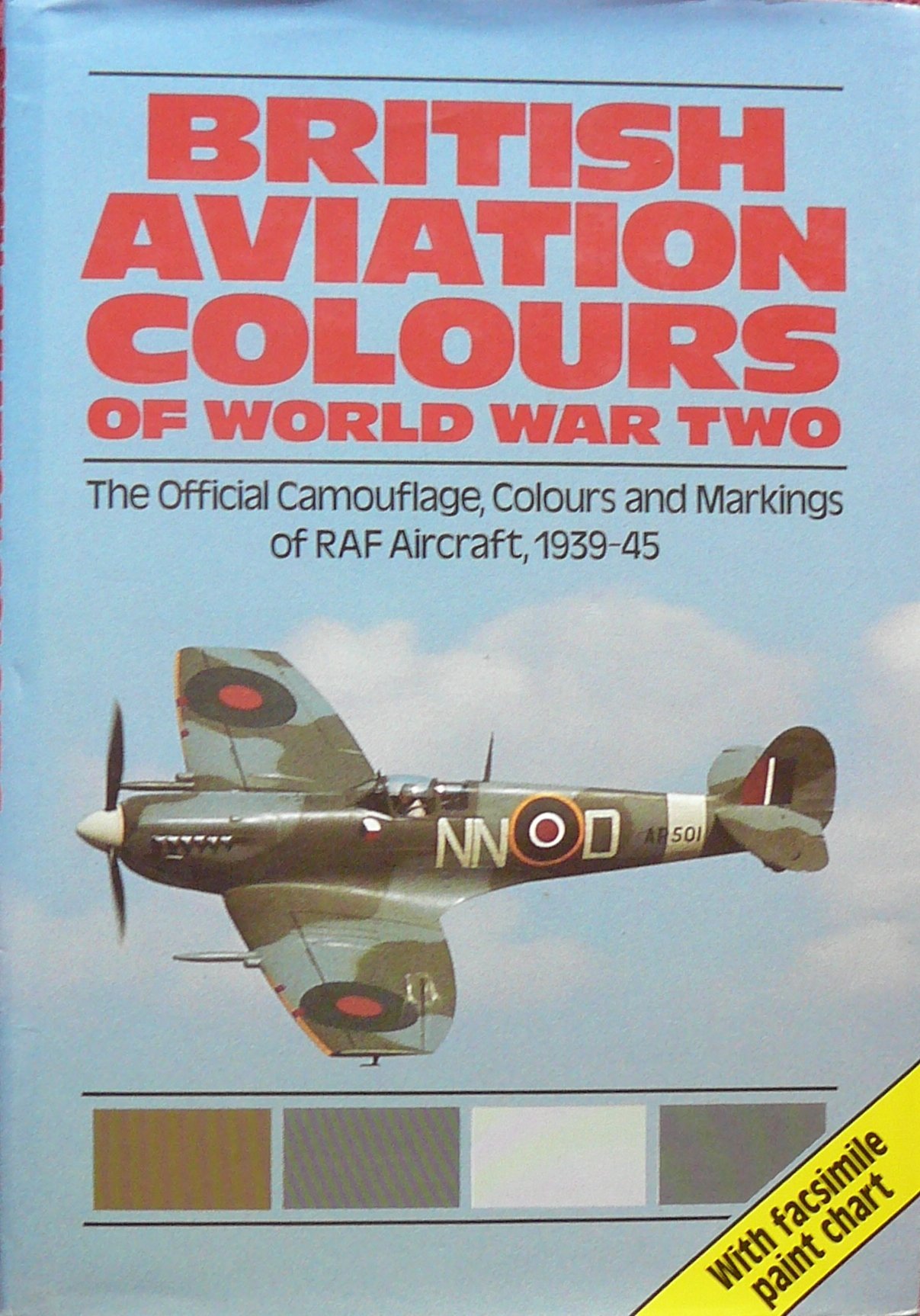
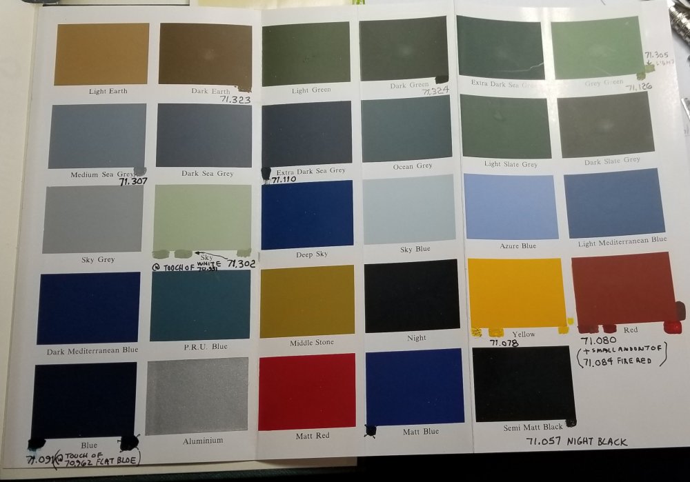
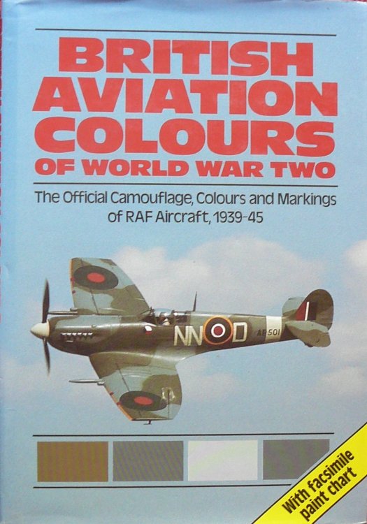
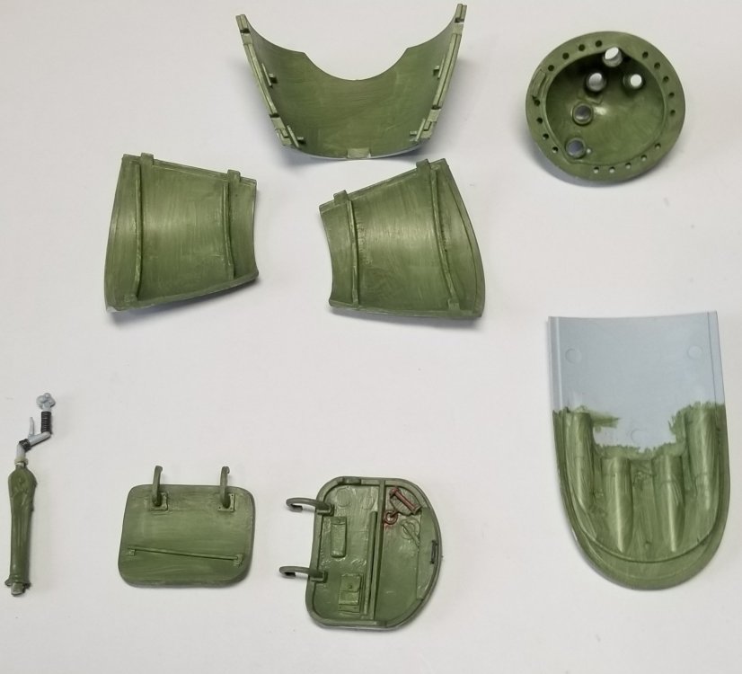
Ok another update These are all the colors I will need to paint the Mossie. They come from this book and will be Vallejo model air. Most will work straight out of the bottle, some I had to modify to match the paint chips from the book. Cool book, has alot of paint info on RAF aircraft from 1939 to 1945. This picture shows the cockpit floor and some bulkheads. I added the white plastic pieces and the lead wire basde on photos and books. The small straps over the wire are bits of 0.7mm masking tape cut to size This are some of the parts I modified withe the first coat of RAF interior grey/green. heres a shot of the seat temporarily in place. Thanks for looking let me know if Im going down the right path...lol Ron G

-
Thanks Anthony Coming from you thats high praise Ron G
-
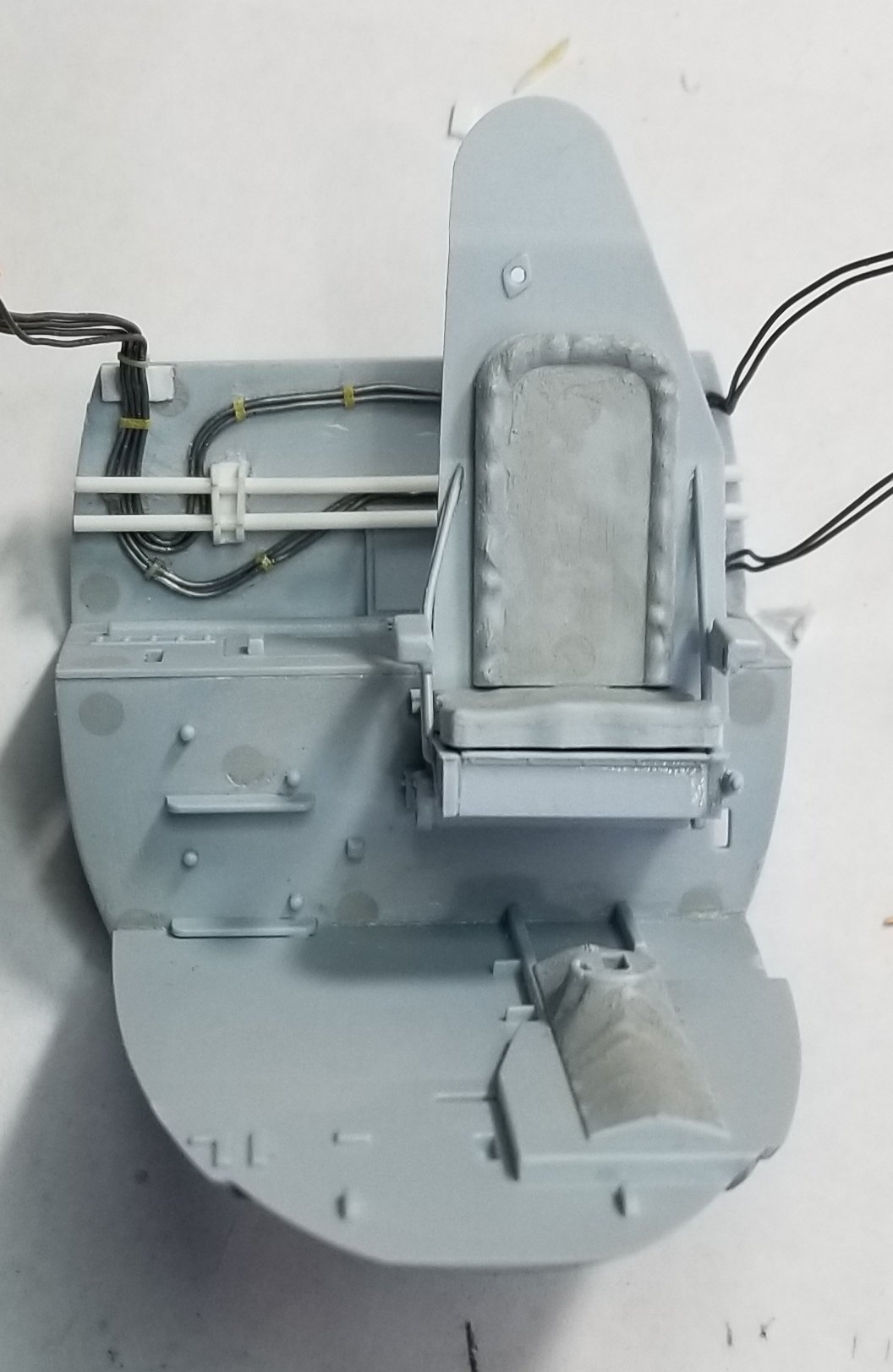
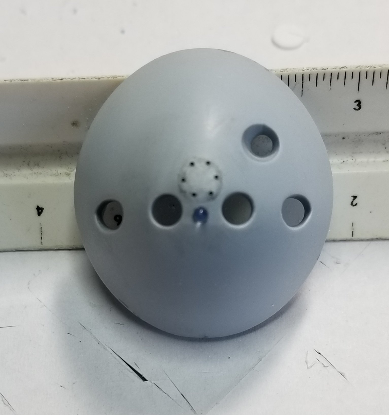
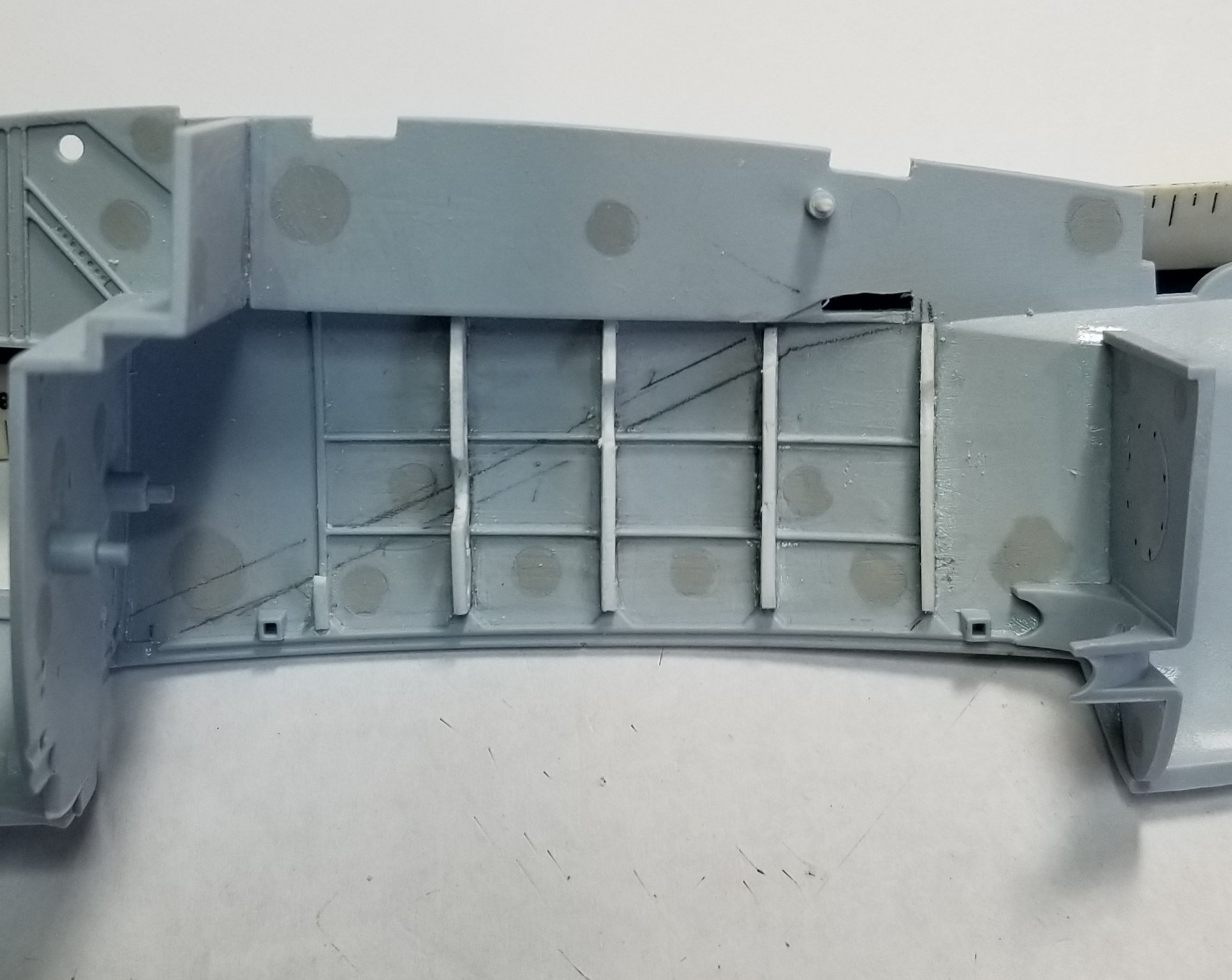
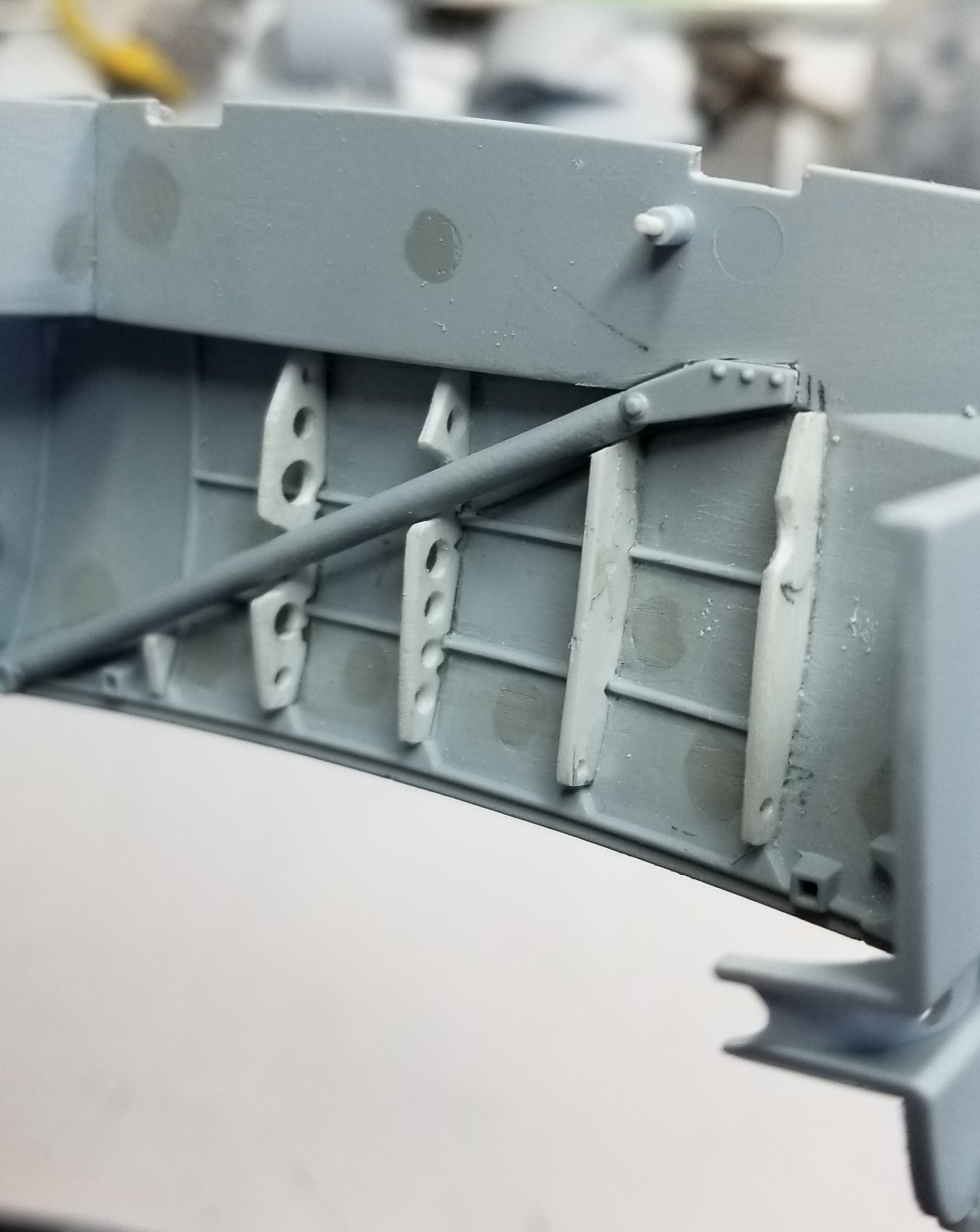
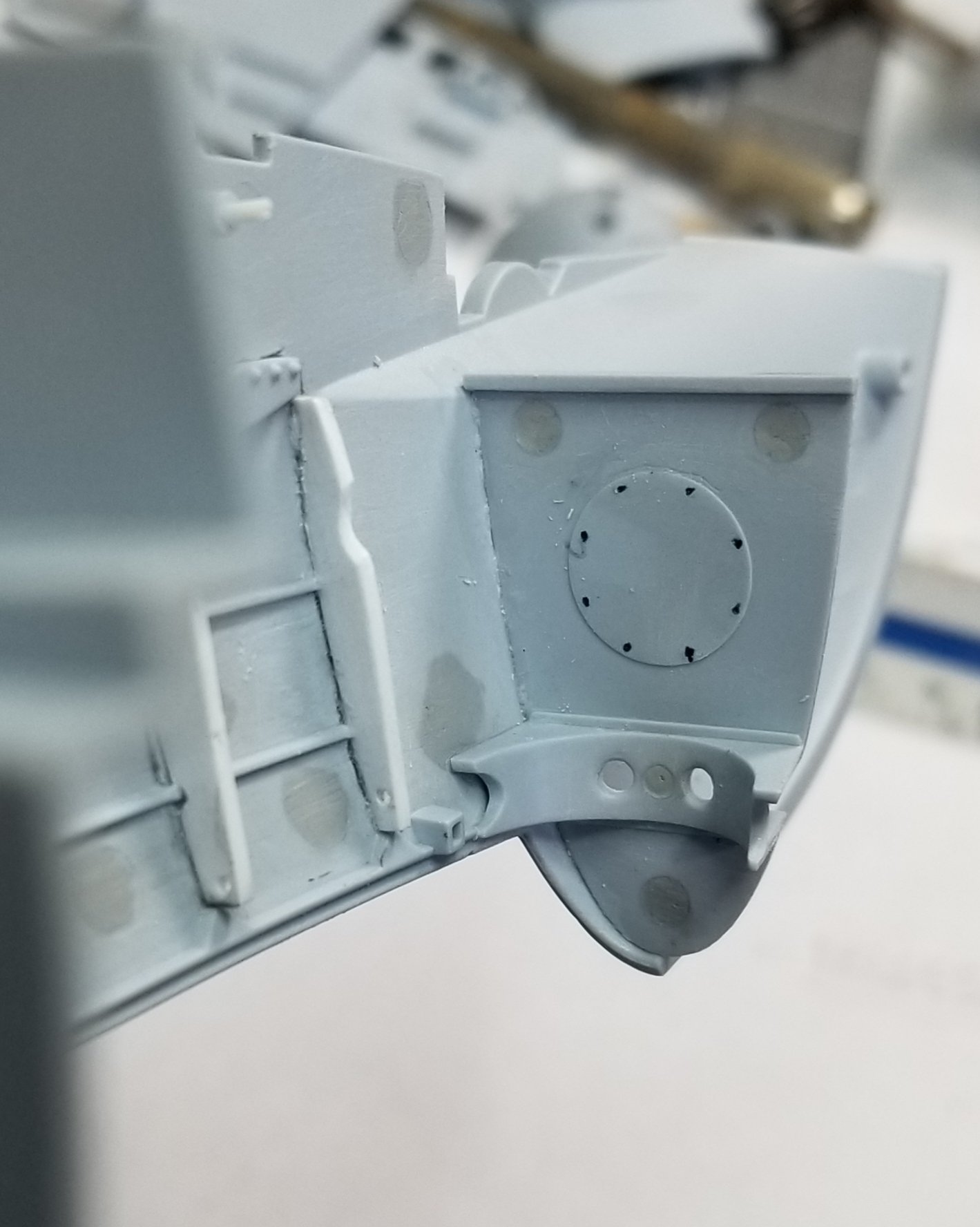
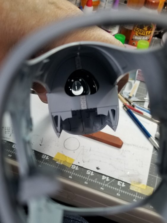
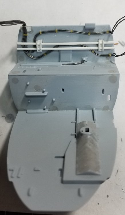
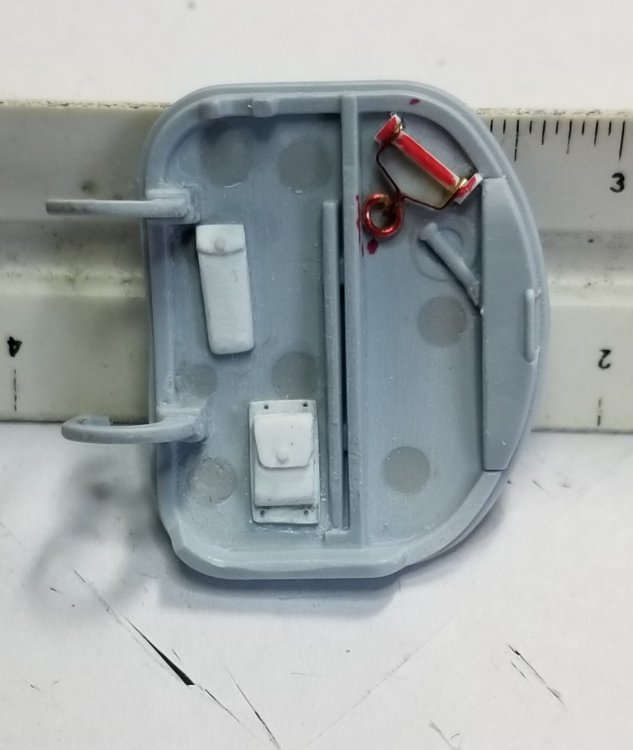
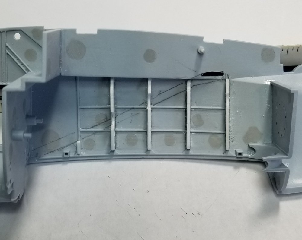
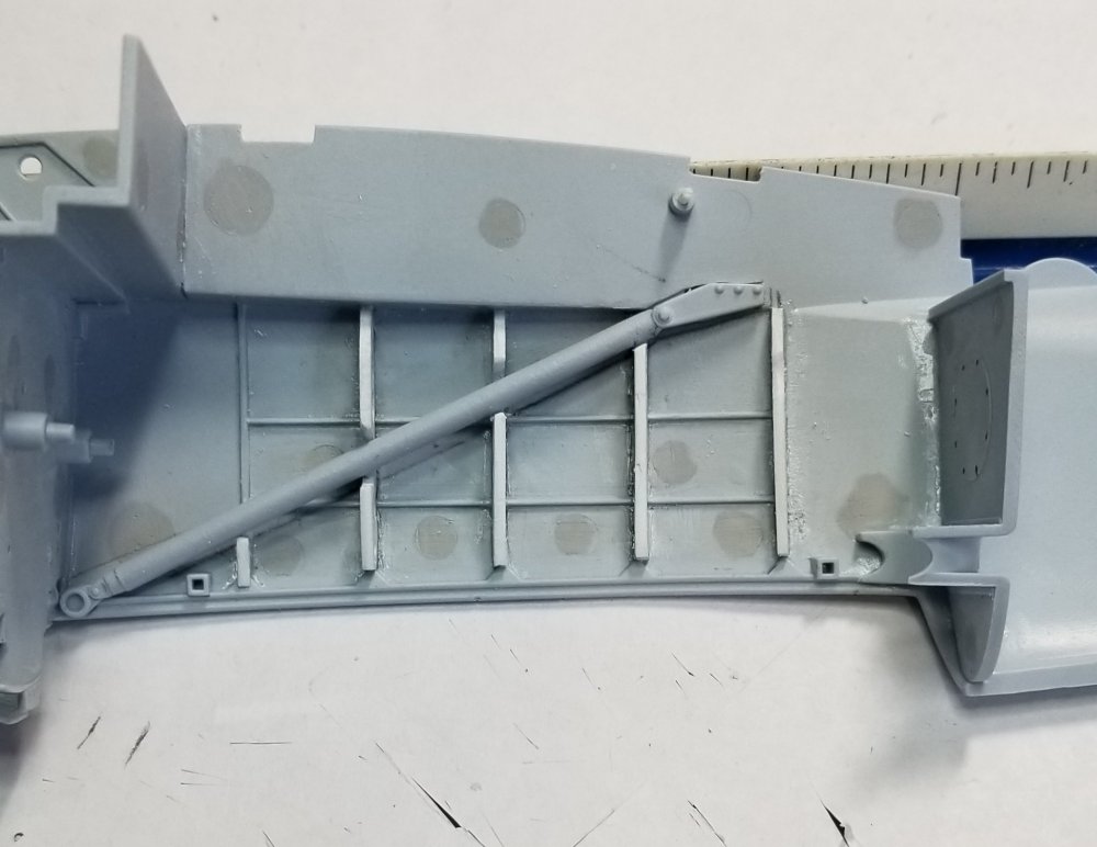
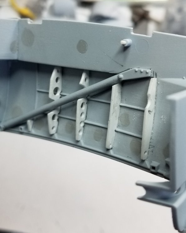
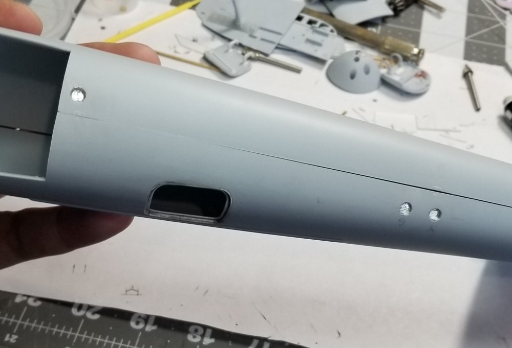
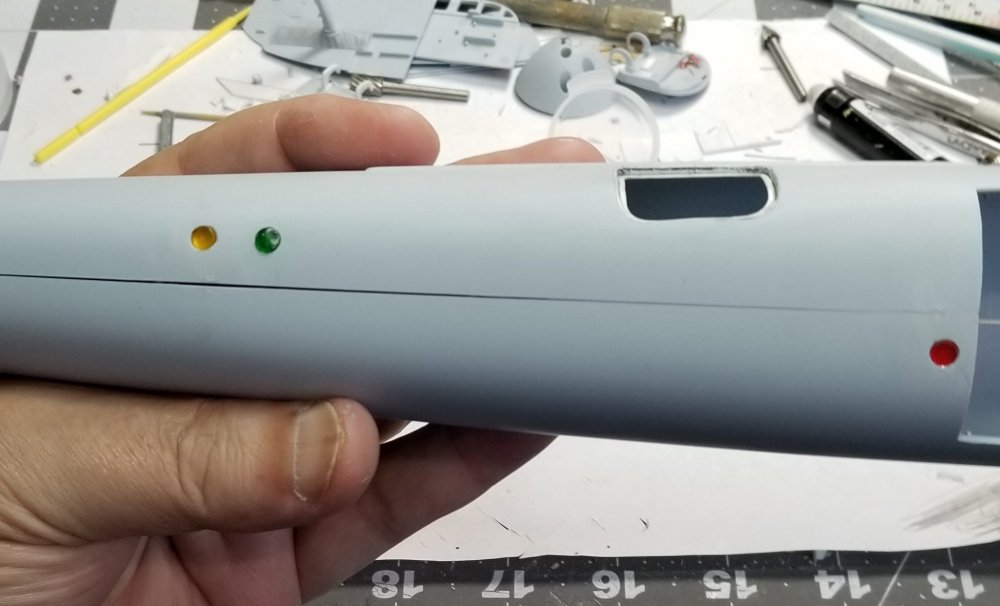
Hey all Just a little update Added the cover plate over the AI rader hole and added the light between the two inner machine guns. Added some detail to the inside of the door. The two small pouches are made from card and the emergency door release handle is made from some scrape photo etch and misalanious stuff from the scrapes box. Inside of the engine nacelle. showing one of the landing gear braces. this view shows the internal ribs I added. These are from photos of the real thing. Rear bulkhead in the nacelle. Holes added for the identification lights. View showing the lights in place. These are made from colored acrylic rods from Plastistruc 5/32" dia. There a bit small in diameter there 3.875" and should be around 5" diameter. This will be part of the diorama painted in RAF colors and pulling a bomb trolley loaded with 3" rockets. Thats it for know. Ron G


-
The shrouds are what I really need, I can modify the kit exhausts but the shrouds would be difficult to scratch build. The radio would be great, if he's interested in giving me a copy of the STL file I can print my own on my 3D resin printer. Any more progress on your Mossie? Ron G
-
Don't forget to add the outer spark plugs and leads, for some reason Tamiya didn't include tese on the Mustang and Spitfire not sure if there missing on the Mossie cause I don't have one. Not to hard to add though. Looking good so far. Ron G
-
I know they are out of production, but I believe Anthony has a set and I'm trying to beg him to sell them to me Ron G
-
Hey Anthony Thanks I hope I can do as good of a job as yours. You wouldn't be interested in selling those please? Do you have the shrouds to?
-
Hey Drifter YES it can be, but I have told myself to go very slow and test fit often. The first thing I did when I opened up the kit was remove the sprues from the bags and go over all the parts with the instructions and found all the pin marks and filled them with Mr Surfacer 500, some I had to do twice. Then I tackled the landing gear. I did another post on them. I added brass tube and rod to them because they are way to weak on there own. Also I didn't want to use SAC gear cheap white metal and they are to hard to attach to the plastic. Mine will be attached with tamiya extra thin and some CA glue. I plan on doing it as L 3, PZ474 I know it is not a plane that actually was in WW2 but that plane is so cool looking in extra dark sea grey and sky with the invasion strips. Ron G
-
Hey all Anyone have a clue if the Mossie had identification lights, the red, green, amber ones, and where they would be located at and what size diameter? Thanks Ron G
-
Thanks crazypoet Just beginning this project it's going to be a llooonnggg ride...lol, so grab your pop corn and a brew, buckle up and hold on, going to be a bumpy ride
-
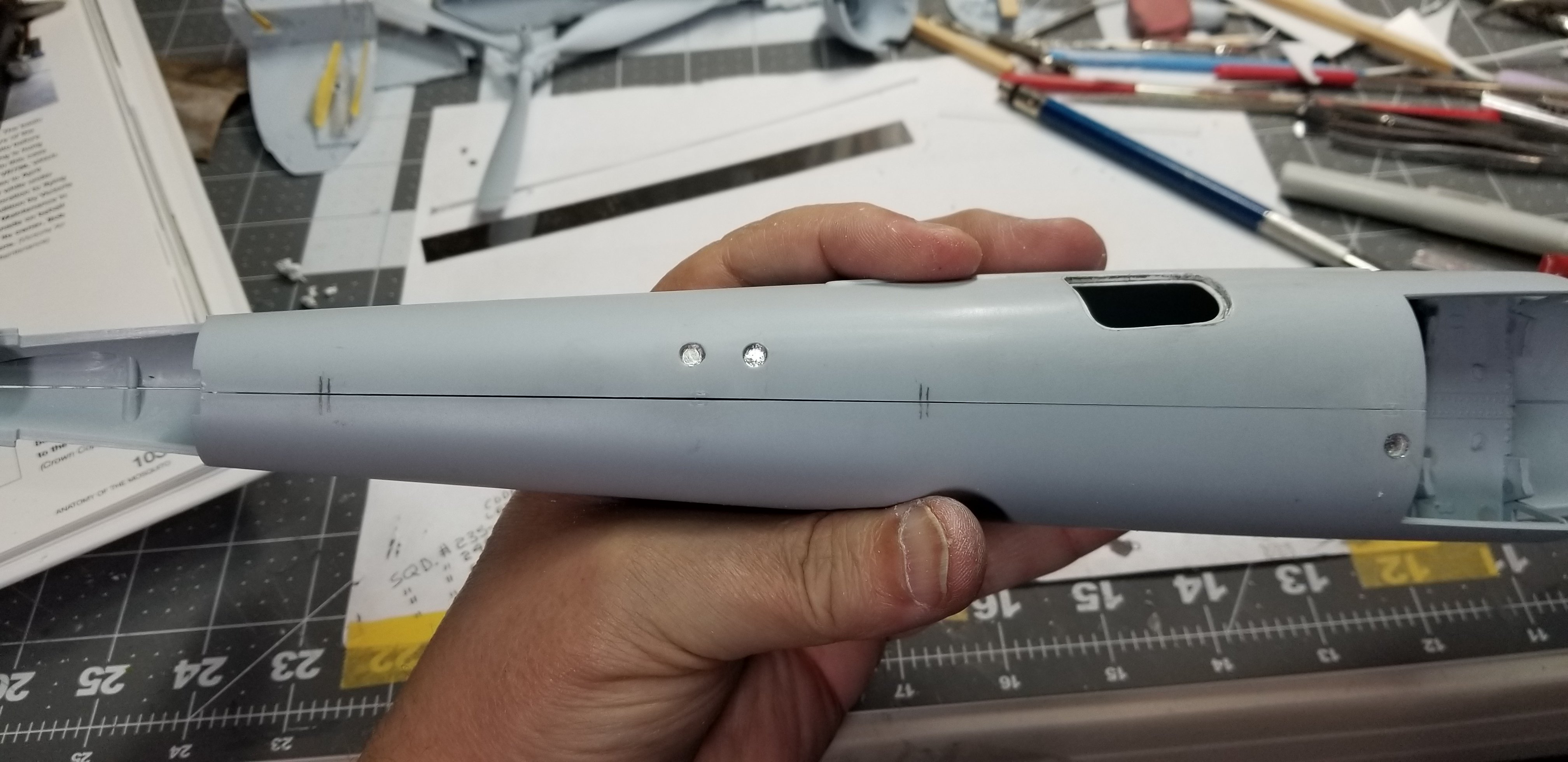
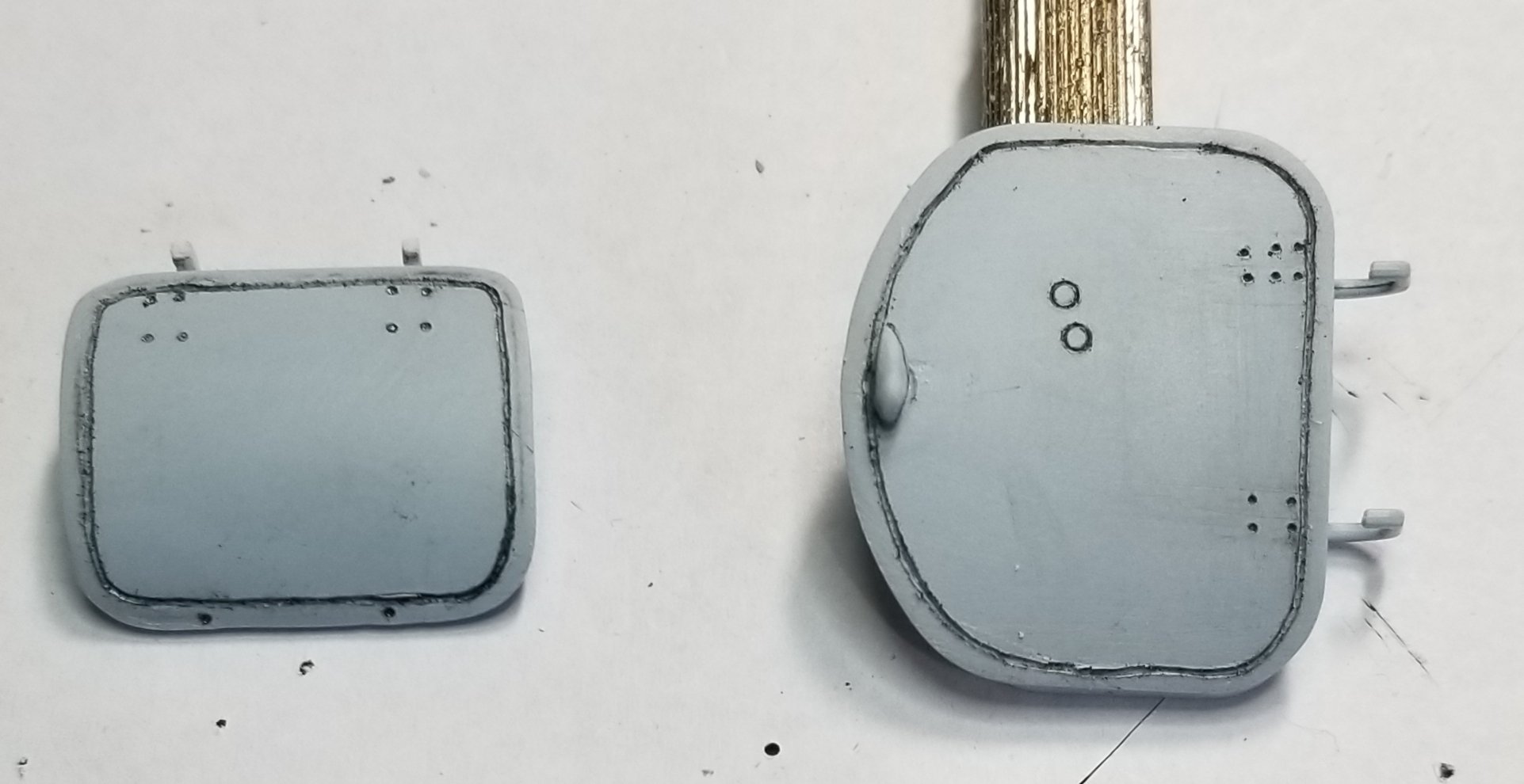
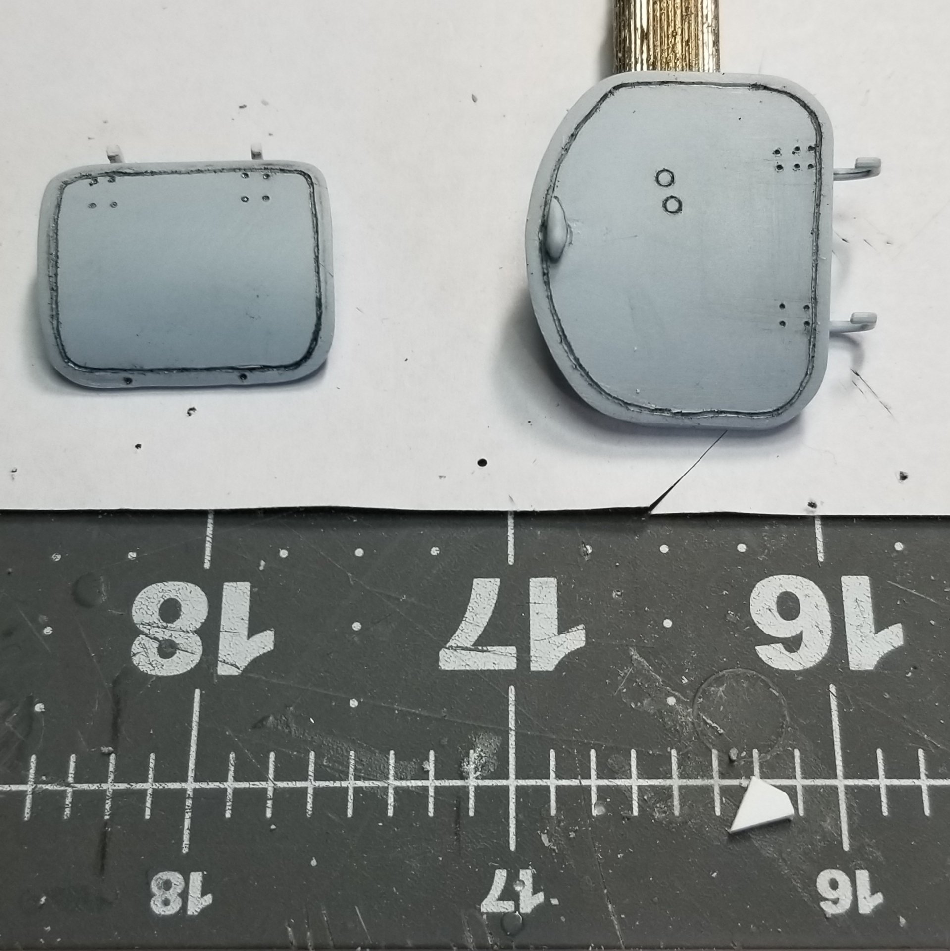
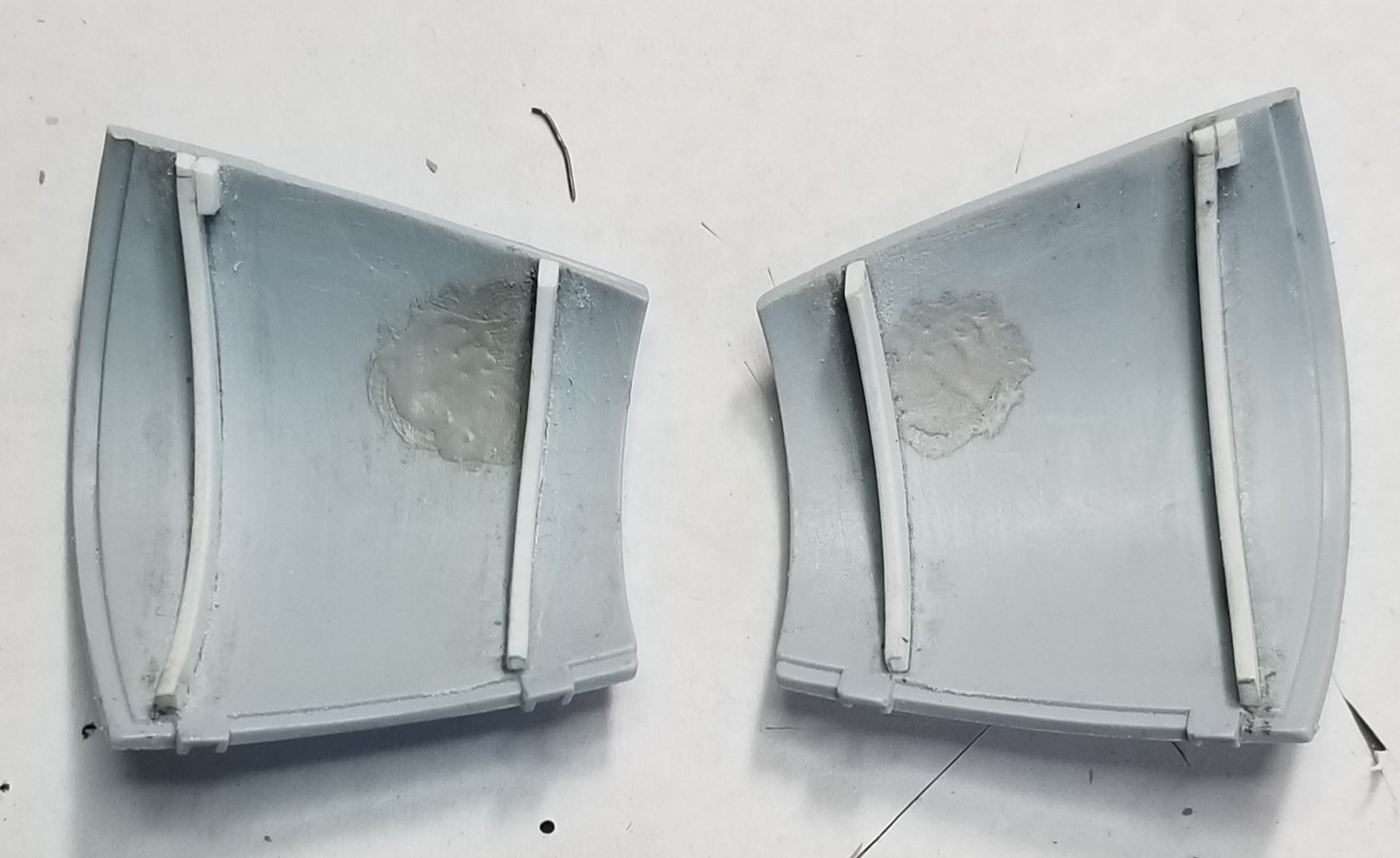
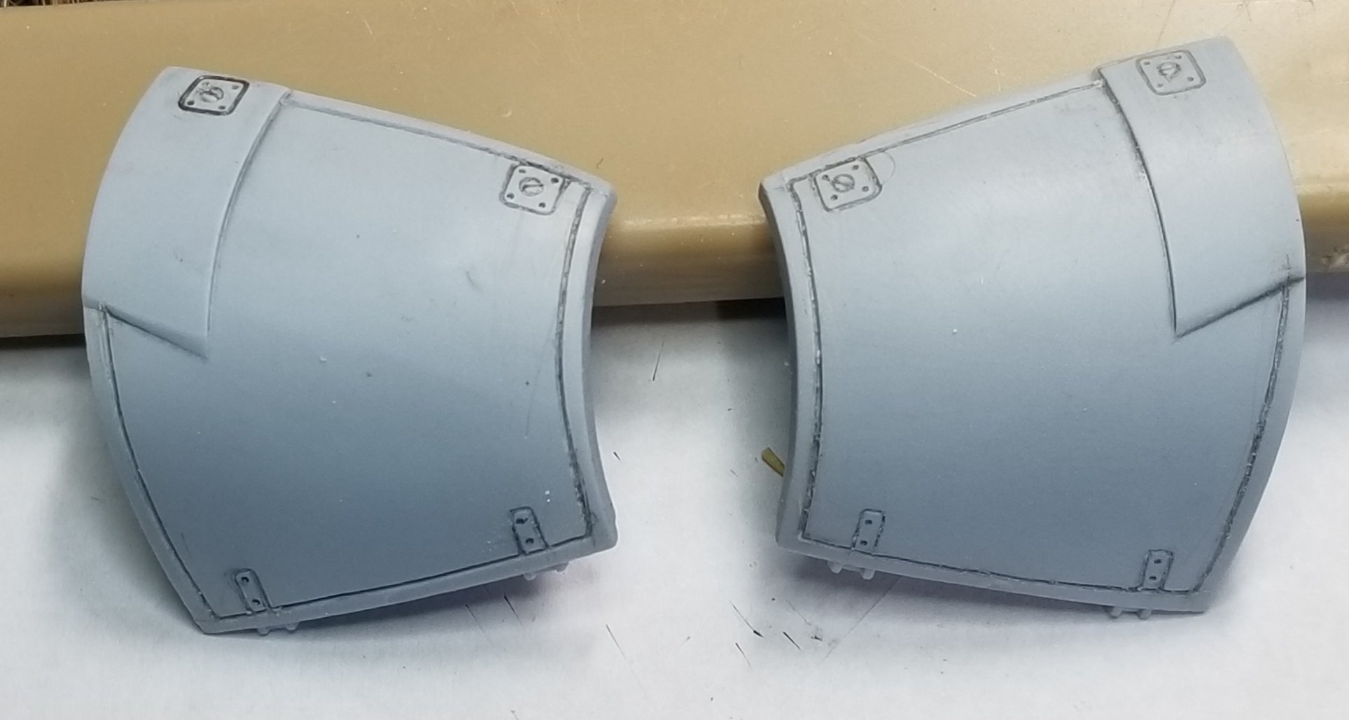
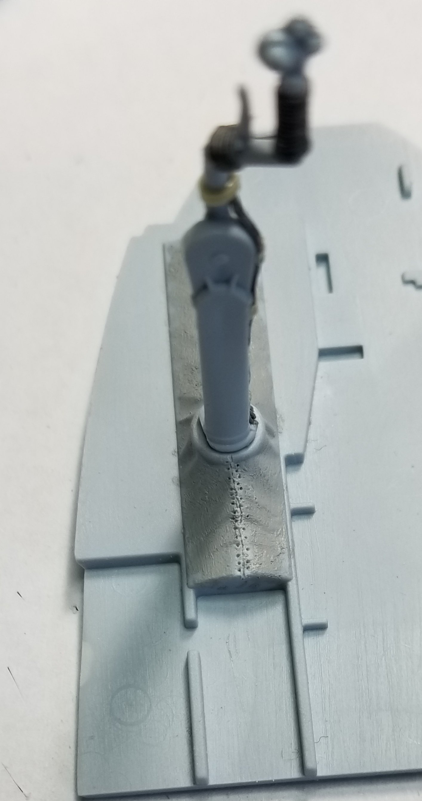
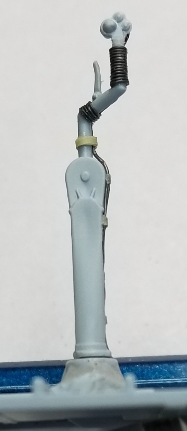
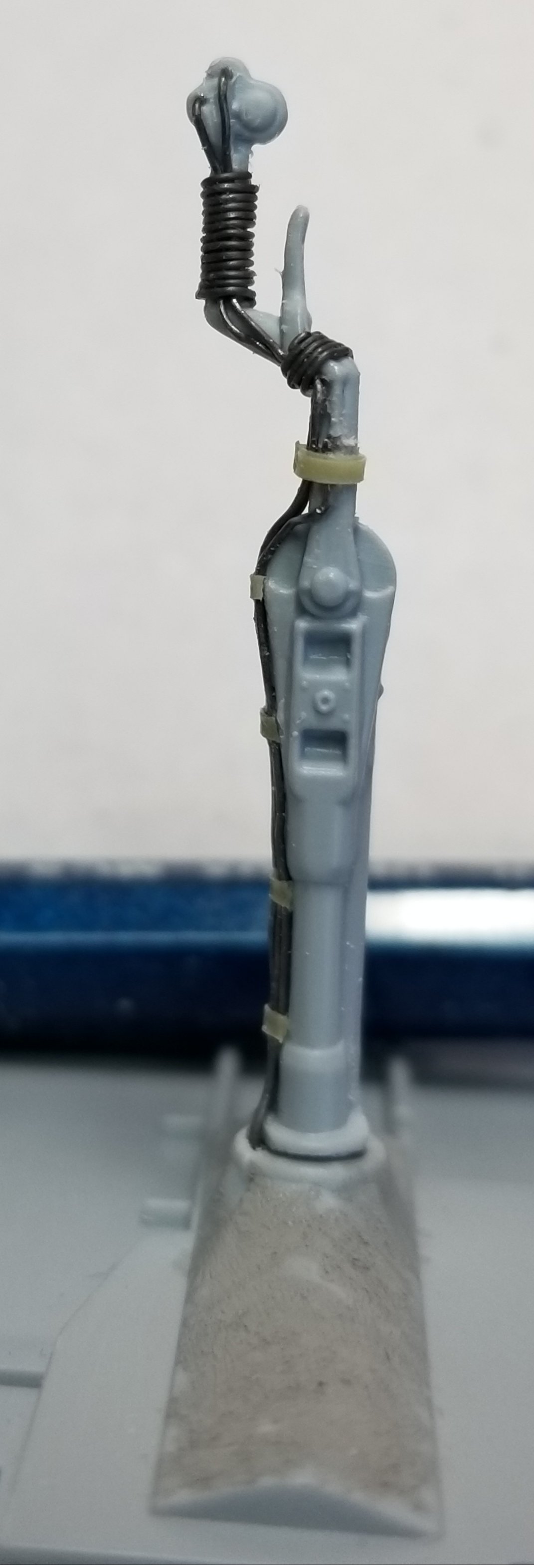
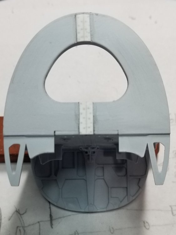
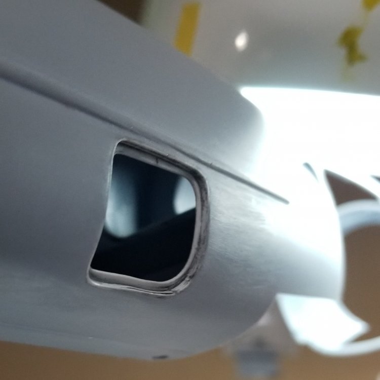
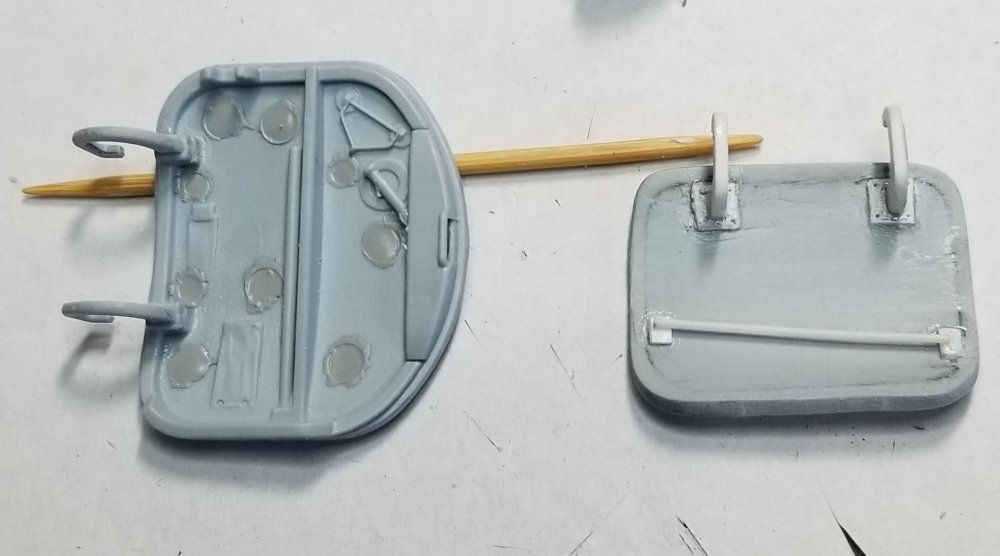
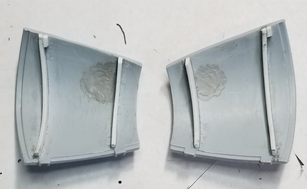
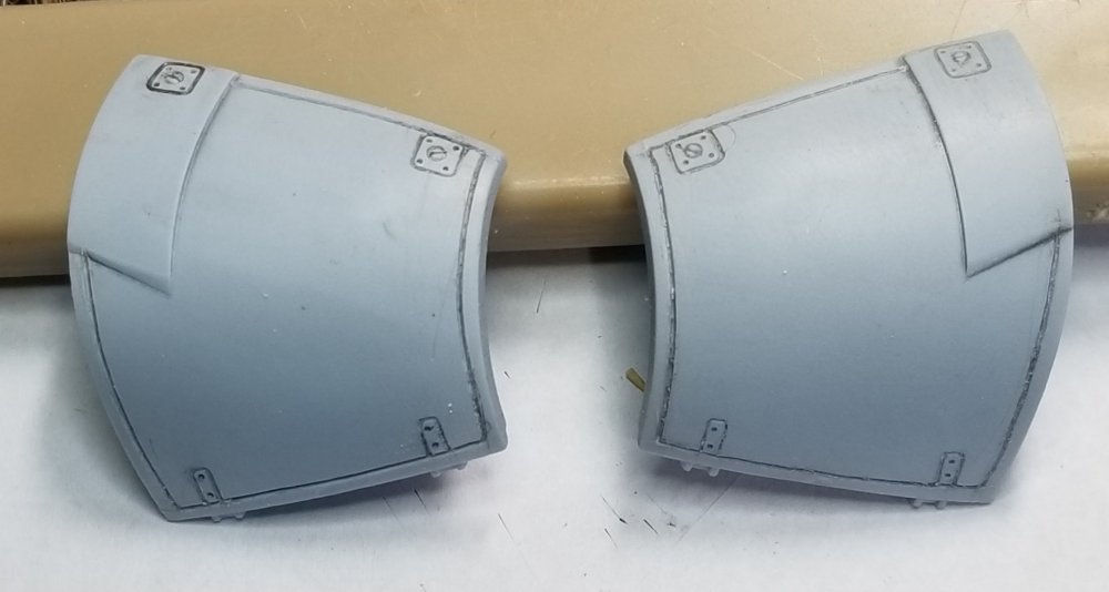
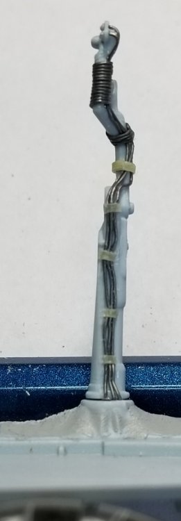
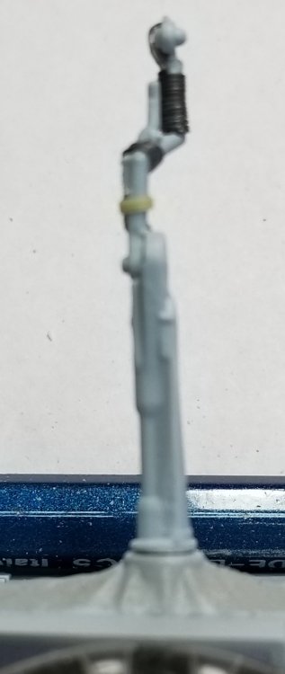
Hey all I've put the Hellcat to the side for awhile, waiting for Alistair at Aerocraft to finish his landing gear. So what to work on next...hhmmmm..I've got it Airfix's 1/24 scale Mosquito FB VI. I started by modifying the landing gear, added metal tubes and rods to stiffen em up. I covered this in a separate post. Now I'm working on the fuselage bits. I cut out the rear access hatch and added some hinges and the latch mechanism to it. I added the inner flange to the opening in the fuselage for the hatch. The hatch will be displayed in the open postion. Also I've added some surface detail to it (see pics) I also added the missing surface detail and a handle to the entry door, this will be in the open position also. Rear hatch on left, entry door on right. That door knob was a real PITA! I lost it twice to the carpet monster and had to start over again. Inside view of entry door and hatch. This needs to be cleaned up and primed. This ones just to show size. Next I cut the hatch/cover over the front .303 Browning machine guns into left and right halfs. Airfix kinda dropped the ball on this making it one piece. I added some interior ribs that were missing from the kit parts. I also added some surface detail that was also missing from the kit parts (see pics) these modified parts still need to be cleaned up and primed. Inside left and right hatches. This shows the scribed in lines and latches. Next I started on the cockpit area, first I added some detail on the canves boot around the control column to simulate the stiching at the rear of it. You'll never see this but I know it's there. I started on the control column by modifying the thickness of the hand grip. I shaved it down being very carful not to break it. I carved a groove down the length of it to accept the 0.015" lead wire for the cannon and machine gun firing buttons. I then ran two lengths of 0.015" lead wire down the column from the back of the fireing buttons to the base of the column. Super glued these to the column Then I added the line from the brake lever on the column, down next to the previous wires to the base of the column. Next I wrapped the hand grip area with some 0.010" lead wire and added some more just behind the brake lever. Super glued this, then added some wire wraps from some 1/32" pin stripping tape to represent wire ties down the column. (see pics) Pilots view of the control column. Side view showing the wire wraps and wires going into the base. Rear view of control column showing wires going from the firing buttons down the column. The othe side of the column. This needs to be cleaned up and painted, then it will look really cool setting between the pilots seat and instrument panel. Thanks for looking let me know what you think. Ron G


-
Hey Hubert If you use there thinner (Vallejo) it works fine. The problem is Vallejo paint is a WATER based acrylic. The others are lacquer based acrylics. Ron G
-
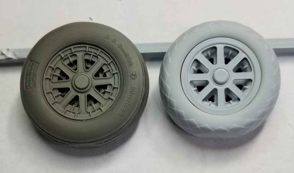
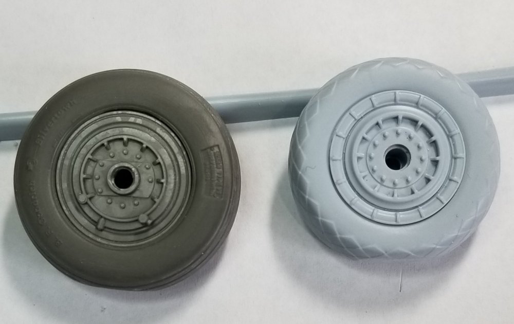
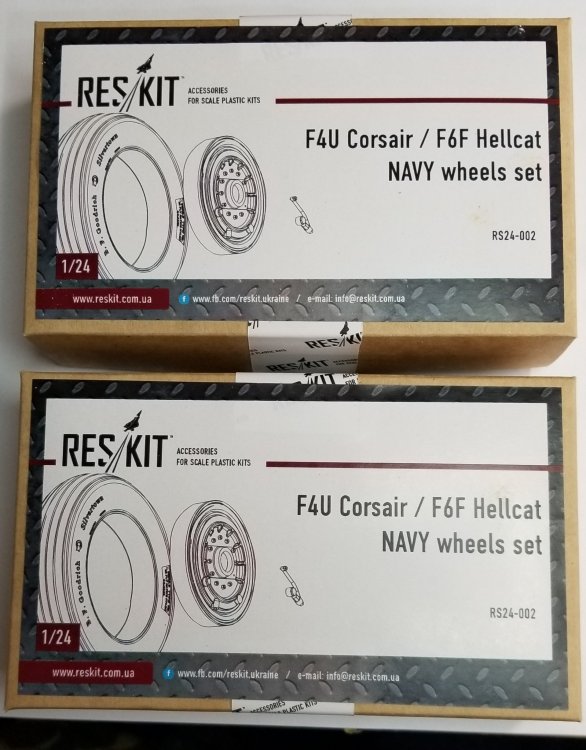
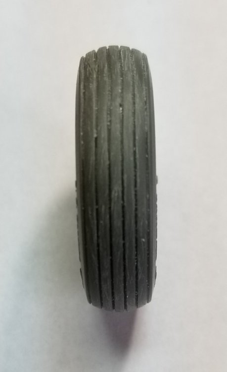
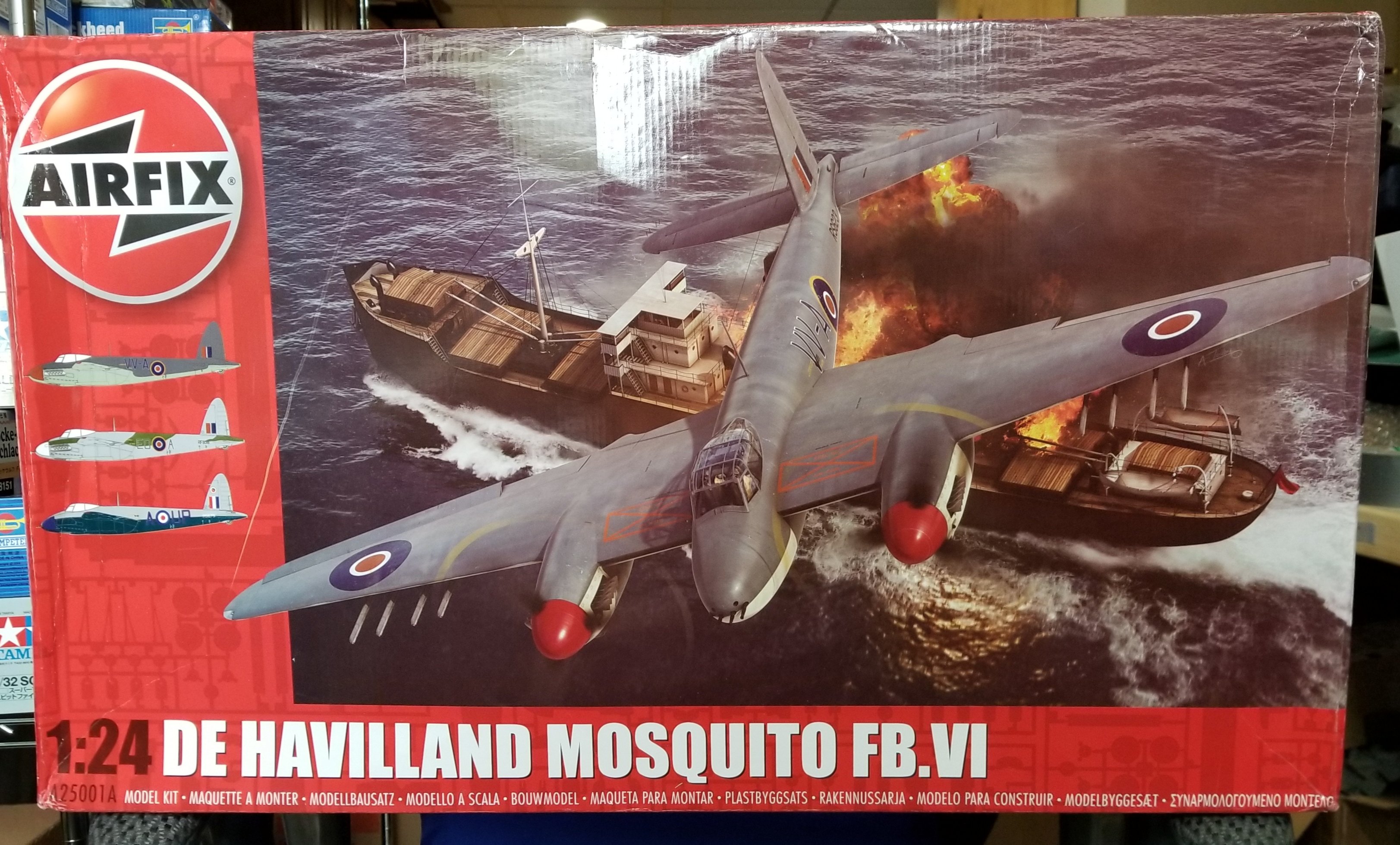
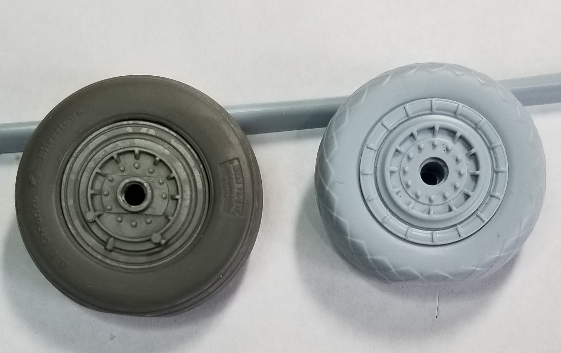
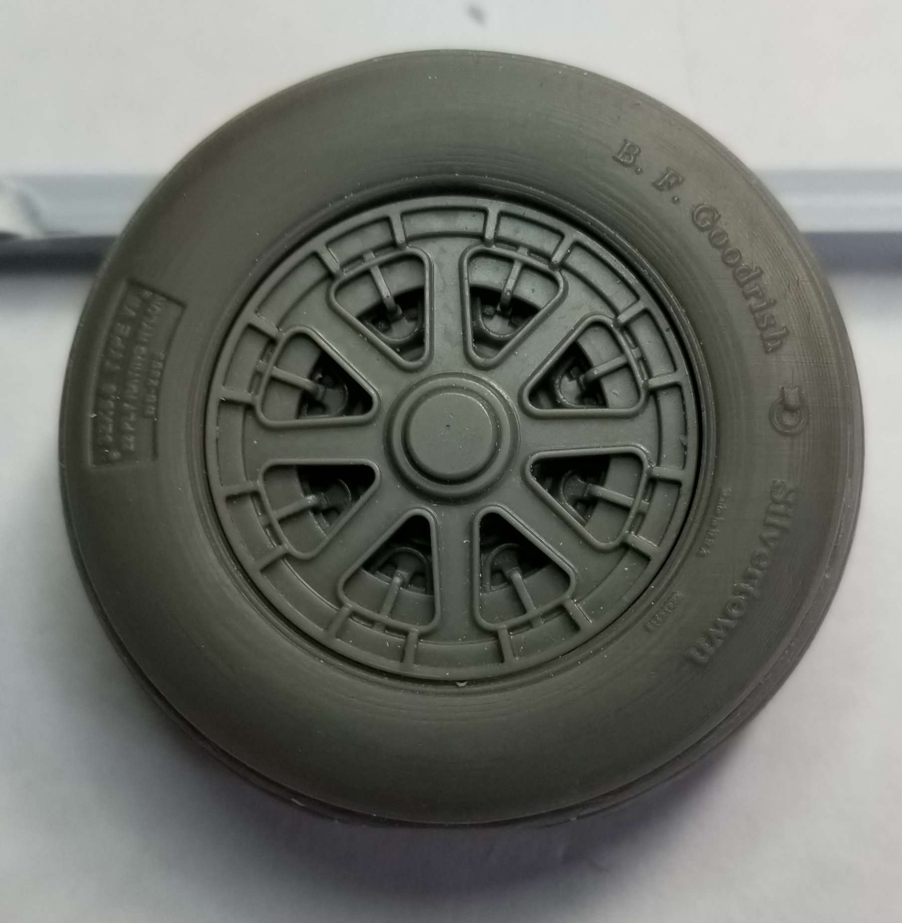
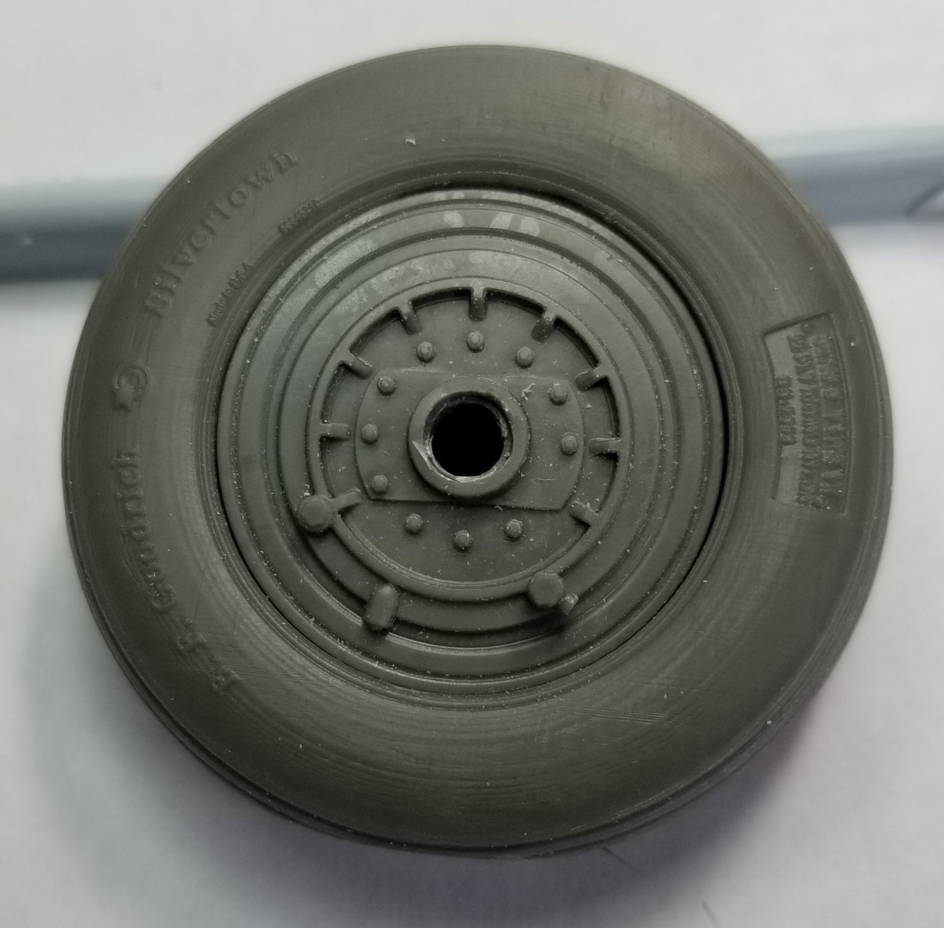
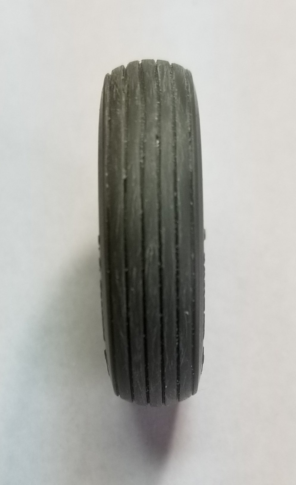
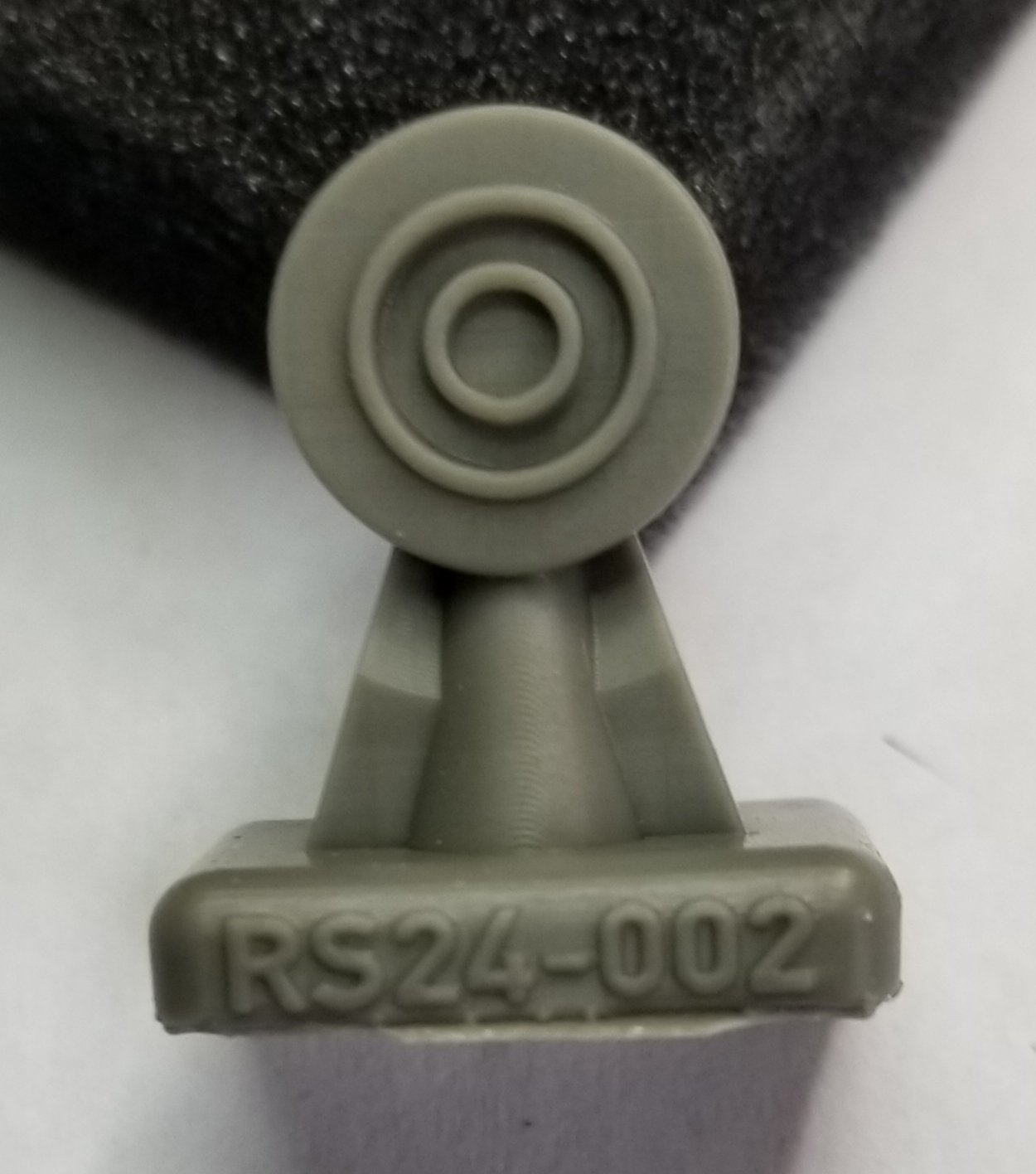
Hey all A little update, the wheels & tires from ResKit came in the mail. It took awhile had to come all the way from the Ukraine. The tires look fantastic, but I wish they had the diamond tread pattern. They have B.F. Goodrich Silvertown on the side walls along with the tire size 32 x8.8 type VII also there is some smaller print by the rim area, but it's to small to read.There is no flat spot so you have to sand one in. The wheels come in two pieces a front and a rear. The rear has a VERY small part that you have to add, I'm not sure what it is, but I already lost one pair to the carpet monster. The wheels are really nice and have all the detail of the real thing. Here are some pictures that show the difference between the resin ones and the kit ones. Here are a few more pics. Two sets for two kits. Front Rear Side view These are the VERY tiny hose parts that are very delicate! Rear wheel, its so so, not sure if its better than the kit one. Well that's all for know. Ron G 23031.pdf