Fidd88
-
Posts
196 -
Joined
-
Last visited
Content Type
Profiles
Forums
Events
Gallery
Everything posted by Fidd88
-

Frazer Nash FN5 gun-turrets
Fidd88 replied to Fidd88's topic in LSM 1/35 and Larger Work In Progress
You may laugh, but the Brownings do actually incorporate a spring loaded "working parts" which have a sliver of very fine plastic, a "reed" if you will, protruding from underneath. This was supposed to flick against 2-3 similar "reeds" within a sound-box for want of a better phrase, so that when the guns were cocked (with the modelled cocking wire), as the working parts flew forwards or were drawn back, it was supposed to make an approximation of the sound of the guns cocking. Unfortunately, as the guns were the first part that I made, I hadn't quite got the required tolerances correct, nor indeed the mechanism, so it didn't work. Silly, but great fun to try and devise and make. Admittedly I had an O level (roughly high school pass) in technical-drawing, so had some basic skills to learn CAD via Autodesk Fusion 360, which you can still download and use free via the start-up/hobby use license, and it took me a month of doing tutorials to learn the basics, and 6 months to get really quick, by the end of the year I'd 'slain the beast' of constructing compound curvatures. This is something all of you can do, it's just a matter of a few weeks hard graft learning the basics. One of the really nice things about fusion 360 is that there are several ways of drawing the same 3d model, some are efficient, some less so. After a time you experiment with as-yet-unused commands and discover the faster methods. Coupled with 3d printing, it's a very powerful model-making tool. What's currently lacking is the definition, relative to injection moulding. So any cylinder less than 0.8mm diameter is likely to be very weak, if it successfully prints at all, any feature less than 0.5mm may be lost, and tolerances are circa +/- 0.1mm. Sheets of material can deform at the corners due different cooling rates. In short, you have to experiment a bit to find the limits of what is possible. In SLS Nylon, the finish is approximately that of an "extra-strong mint", so if putting two parts together I under-size each by 0.1mm on the abutting faces. When attached to each other, the overall dimension across the two parts then comes out as per the drawing. Fusion 360 has excellent tutorials, and a very active forum for getting help. There are specific tools available to facilitate others following your drawing methods, and making changes, although I only needed to use this once - with compound curvatures. I think I succeeded with this model on the "bumble-bee" principle, I never realised I couldn't do it, and just kept battering away at problems and learnt new skills until it nevertheless started to take shape. -
Frazer Nash FN5 gun-turrets
Fidd88 replied to Fidd88's topic in LSM 1/35 and Larger Work In Progress
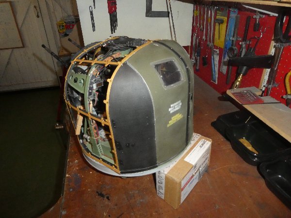
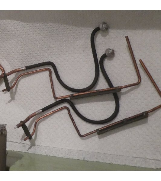
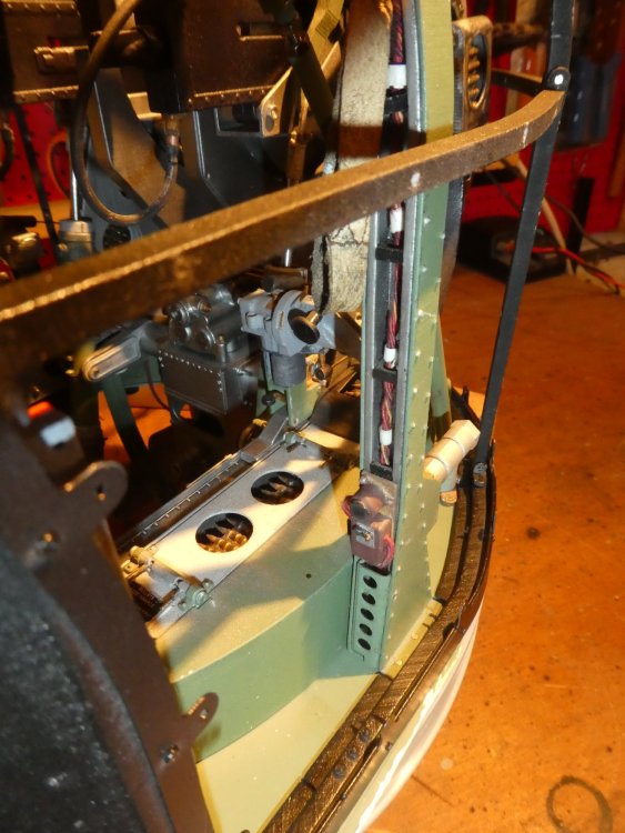
Hi all, Lately I've been painting the "tub" for the rear-turret, although I can't fit it until some packing-pieces arrive. In the meantime I've assembled and painted the dozens of "hydraulic" pipes. I've found that they're almost impossible to fit with the pneumatic hoses in situ, so all that has been stripped out and one set of "hydraulic" pipes fitted - but not glued. Gluing will only occur once the pneumatic hoses have been also fitted.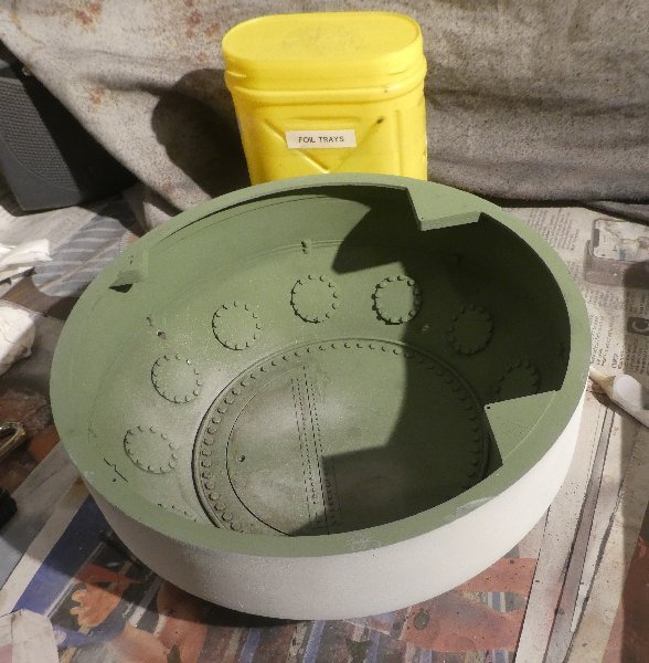
-
Frazer Nash FN5 gun-turrets
Fidd88 replied to Fidd88's topic in LSM 1/35 and Larger Work In Progress
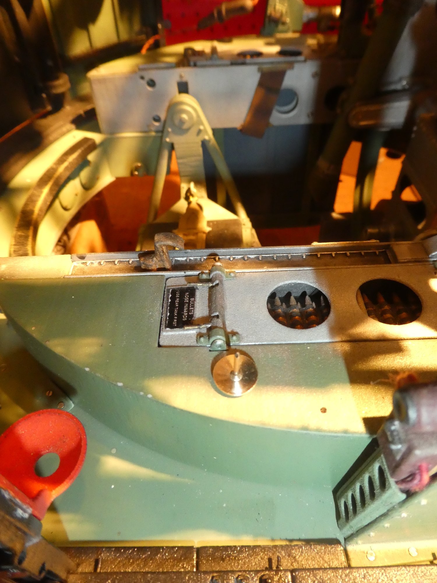
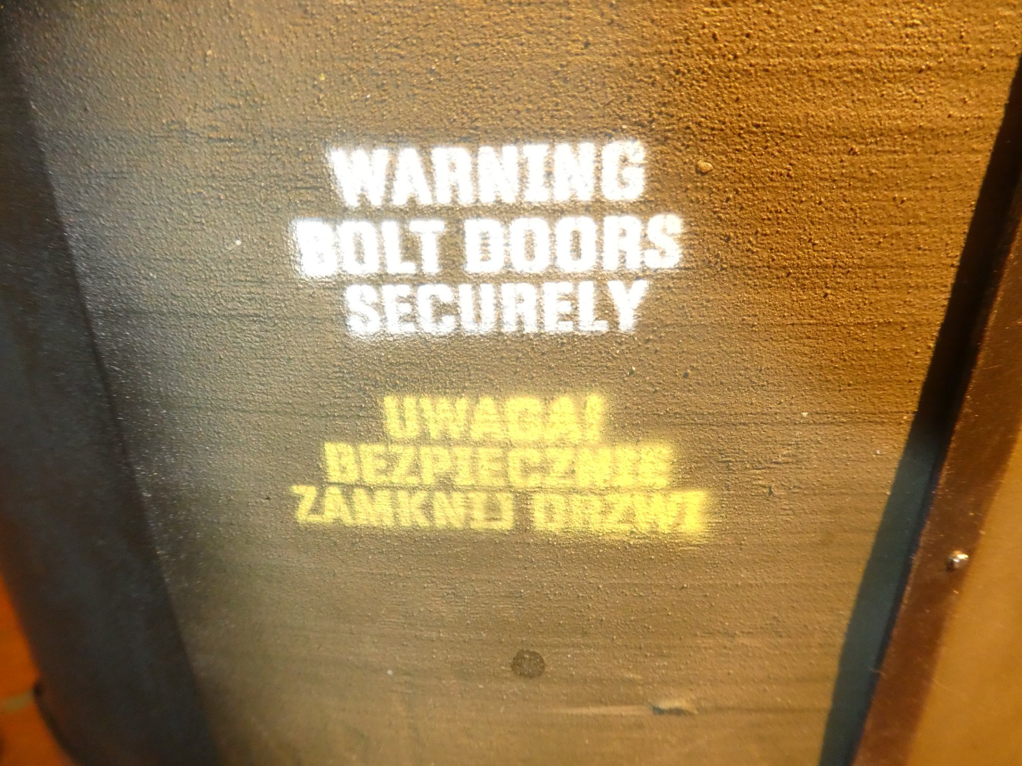
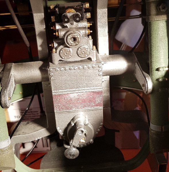
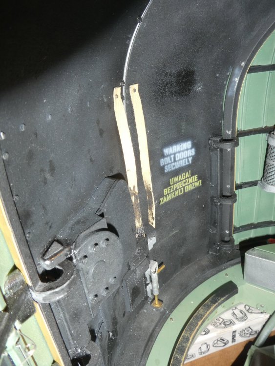
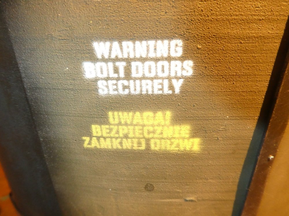
Cheers, yep the bottom one is real. You should do the same with your and close-up shots of the wheel-bays etc on your P51. Yesterday I received a photograph of the engraved text on the console of R for Robert's (The Wellington raised from Loch Ness) front turret.. My first thought was to simply retype the test on a suitable background and put that on a decal. Instead I decided to manipulate the photograph itself into a decal. The model photograph was in very strong artificial light, in daylight the colour and contrast are darker and more respectively, and by naked eye, much clearer.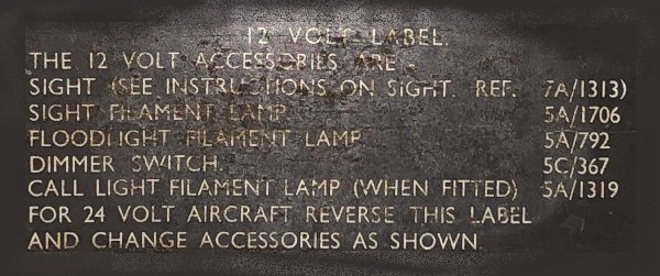
-
Frazer Nash FN5 gun-turrets
Fidd88 replied to Fidd88's topic in LSM 1/35 and Larger Work In Progress
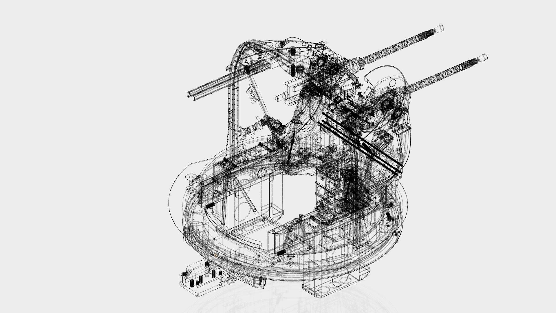
This evening I've been getting ready for the Gaydon and Brooklands events, and I thought it might be fun to take a picture of the model from a similar angle to a book illustration, and greyscale both. There are a fair number of differences. Not all of them are "errors", as the turrets were in perpetual development, so nowadays you will not find two museum examples that are the same, or even similar in some cases! Furthermore, as many museum turrets are only accessible from certain angles, and historical ones are taken often from very similar angles, the models are necessarily a "composite" design taken from features in probably several dozen FN5's.
-
Frazer Nash FN5 gun-turrets
Fidd88 replied to Fidd88's topic in LSM 1/35 and Larger Work In Progress
Thanks, but I try not to think about the "scope" of it. It's more a case of 'putting one foot in front of the other' rather than working on the entirety of the project, not thinking much beyond which beans need to be in a row before the next tasks can be got under-weigh. If I thought through the whole project from stem to stern, I'd be driven potty! This will likely be about it for now, as aside from painting and test-fitting the cosmetic hydraulic pipes, there's only the windows left to do, and they'll take months to make, as I need to: Make an MDF "plug" of the desired shape reduced by 1mm (the maximum thickness of the Perspex), then cover that in resin and micro-balloons, before sanding it back, then sealing it with a glass coat and bringing to a highly polished finish. Then a two part glass or carbon-fibre mould is made of the MDF shape. Then that has to be similarly fettled with to make pristine. Then a resin and powdered aluminium cast is made from the two moulds bolted together. This is then fettled with to make, yet again, a smooth and blemish-free finish. Finally hot Perspex in a frame is vacu-formed over the alloy/resin plug. Then the real work begins cutting up those windows into panels and bolting them to the sub-structure of the turret. Oh, and I need to do all that twice for two different moulds to make the windows for both turrets. And that is why I don't think about the "scope"! -
Frazer Nash FN5 gun-turrets
Fidd88 replied to Fidd88's topic in LSM 1/35 and Larger Work In Progress
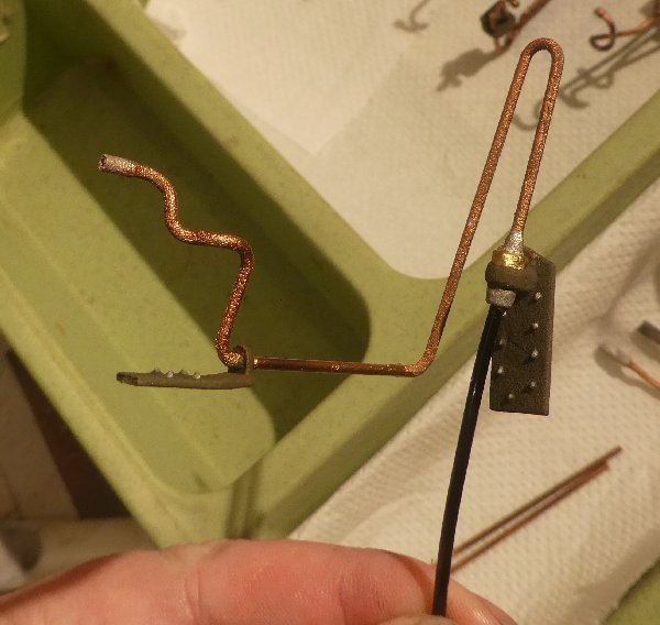
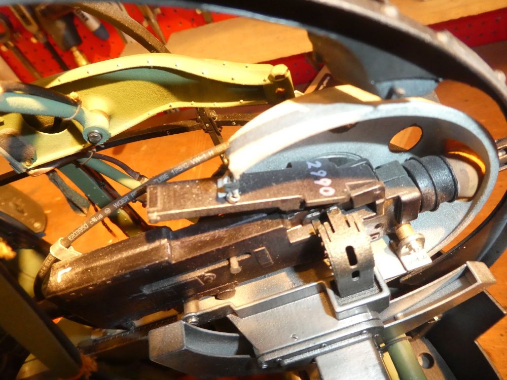
Truly. Today I started assembling the "cosmetic" ie non-functioning hydraulic pipes. In order to save money by being able to make the "nests" of parts more efficiently packed with parts, I had omitted all straight sections. These were very accurately made from 1/16" K & S metals brass tube which could be glued onto very fine lugs on the ends of 3d printed plastic parts. For now these will be painted and salted away for later fitting. This is because fitting the windows is liable to involve a lot of test-fitting of the cupola, and I don't want to damage the hydraulic lines by fitting them too early. Film: and the preceding one of the working pneumatically driven mechanism for raising and lowering the guns: EDIT: I forgot to mention that I sourced the brass tube first, which was K and S metals 1/16th" which comes out as 1.581mm in foreign. All the torturous 3d printed "pipes" were made from some 8 stock shapes, so as not to have to construct every last "wiggle", and were drawn at the same diameter. Finally lugs were added to the 3d printed lengths to be glued inside the ends of the straight brass tubes. If the lugs were lost in printing, simply drilling a 0.75mm hole and inserting a bit of broken drill-bit of the same size remade the missing lug. Although there's a slight textural difference between the two, once painted they ought look like a contiguous pipe. If not I shall invoke the "4 foot decorators rule", namely if one can't see a blemish at more than 4 feet, it isn't there! -
Frazer Nash FN5 gun-turrets
Fidd88 replied to Fidd88's topic in LSM 1/35 and Larger Work In Progress
Just so. There's obviously a ton of "show-stoppers" that if I can't find solutions for will render it incapable of safe flight. The first is if I can accurately curve extruded alloy channel without great deformation of the cross-sectional shape. I have some ideas for that, but it remains to be seen if that can be achieved. The intention, once the turrets are finished is to attempt to make a geodetic "football" circa 2 feet in dimeter, and then test it to destruction with vibration and shock-loads to see roughly how robust - or otherwise - the structure is. If it's still a go at that point, then the next issue is calculating the wing-loading/weight, and if that comes in ok, calculation of the likely C of G. If all that elicits positive answers, then building the fuselage will commence. In the meantime, I have the turrets done. I started with those as it gave me more time to think about the rather more tricky aspects of wrangling the geodetics. But as Voltaire said "no problem can withstand the assault of sustained thinking". My wife says of this project "it's not the destination, it's the journey", meaning that the endless technical problems to solve are fascinating in their own right. She says other things when I float the idea of hanging the completed fuselage from the sitting room ceiling! -
Frazer Nash FN5 gun-turrets
Fidd88 replied to Fidd88's topic in LSM 1/35 and Larger Work In Progress
Kind of you to say so Peter, I don't think we're comparable in that respect. All your work is highly skilled and careful - proper modelling and scratch-building really - whereas mine is simply creating shapes on the PC and printing them. It's time consuming and looks good, but it really isn't in the same league as what you've done with the P51. My approach is limited by the few materials I use, whereas you move heaven and earth to recreate a "whatyamacallit" in breath-taking detail - and then hide it! (the very definition of a 1st class modeller?) Hehe. For me, it's the engineering of the Wellington that is my primary interest, it's just such an elegant piece of design. I got into it when I realised that the issues which killed this technology stone dead in 1945, namely speed of jet aircraft being higher than the necessarily flexible fabric covering could withstand, and, a better understanding of metal fatigue, which didn't affect Wellingtons as most were struck-off-charge or lost in combat inside 2 months; but which certainly would have affected airliners in longer service. Lastly, it really wasn't possible to pressurise, which put the tin-lid on this technology. I realised a while back that this technology would be ideal for cargo drones, as it confers a great weight-saving over stressed-skin, is easier to assemble and provides around 30% more "usable space" within the airframe. It's also very tolerant of failures within the structure, and "fails soft" as we might say now, rather than breaking up. Looking at that problem led me to the Wellington. My father was an RAF fighter pilot at the end of the war, but like many would be aircrew waiting to be sent overseas to train (he went to 1BFTS in Terrel, Tx) he was sent to bomber-stations to assist with the marathon daily efforts to re-arm, re-bomb, service, repair and air-test aircraft for the next mission. He was put with a Wellington squadron, and it was far and away his favourite aircraft, because like me, he was something of an inventor/tinkerer/amateur-engineer In fact the whole reason he ended up in the RAF was because in 1940, as a teenager he, aided by his brother, had built a home-made bomb, in case the Germans invaded. He didn't forsee that detonating it would set off most of the local sirens, after-which he and his brother were given a 1st class bollocking and invited to join up without delay! It's certainly my intention to fly the turrets, within what is in effect, a miniature Wellington, with the geodetics similar to the original but at scale. I admit I shall be rather relieved when the aircraft has a few flights under its belt, and it's quite likely that I'll do early flights with the turret positions fared over and ballasted. Just in case! Because fixings- rivets and bolts - have different properties at scale from a metallurgical point of view, and they cannot be miniaturised to the same degree as the rest of the structure, I've had to accept using what are in effect over-size rivets, and that impelled a lot of changes to the geodetics sheer and gusset fittings so as not to introduce weaknesses through over-size rivets being set too close together. To the untutored eye, however, it should look pretty close. One day! For now I've just enjoyed researching, fabricating the turrets. I attach an early test of the infamous "bomb". Sadly no footage or still of the one that caused all the trouble exists. I gathered from my uncle that it "weighed several pounds" and took out several windows. It did, however prove that the Anderson Shelter was "fit for purpose" as they detonated it on top with them inside! The logic of which you probably have to be male, 17 and at war, to follow! have you seen the films on youtube Peter?
-
RCAF Lanc 10MP. This really is a group effort
Fidd88 replied to Clunkmeister's topic in LSM 1/35 and Larger Work In Progress
Of course they really only work after they've been immersed in cocktails. No good out of the packet. Now if you managed to devise a white/silver and orange "rescue lanc" cocktail....... -
1/18 P51C Mustang "Lopes Hope 3rd"
Fidd88 replied to airscale's topic in LSM 1/35 and Larger Work In Progress
Astoundingly skilled work Sir. I'd love to master your fabrication of the fuel/hydraulic pipes in and around the wheel bays. -
Frazer Nash FN5 gun-turrets
Fidd88 replied to Fidd88's topic in LSM 1/35 and Larger Work In Progress
Did you ever see James May's "toy stories" series (I think it was called) where he and volunteers built a life-size Spitfire plastic kit? ( -
Frazer Nash FN5 gun-turrets
Fidd88 replied to Fidd88's topic in LSM 1/35 and Larger Work In Progress
Blimey O'Reilly! That's nearly a 4 foot wingspan? One of my earliest memories is seeing those on the news bombing the crap out of the Ho Chi Minh trail, which looked very impressive to my four year old self. I resolved, then and there, never to go to war with America! -
Frazer Nash FN5 gun-turrets
Fidd88 replied to Fidd88's topic in LSM 1/35 and Larger Work In Progress
hehe. I guess that's 1:32 scale? There's no way in Hades I could engineer and build a "working turret" in that scale, not one with motorised moving parts. I might manage down to about to 1:8 but that would be a real struggle. At 1:4,5 is a good scale to work in given the structures, material properties and so forth. The work In one of these is fairly significant, most evenings and weekends for 3 and half years at the drawing board (CAD) and researching, with continuous revisions. I am considering specialising in modelling turrets but the scale will likely be fixed at circa 1:4.5 and hideously expensive, as they take years and months to build, rather than weeks, especially for the first example of a design. Thanks for the praise, it's nice to bring it out into the light after a prolonged build EDIT: Helimadken did produce working FN5a and FN20 turrets for his 1/10th scale Lancaster, which can be seen below, but it's a very different construction technique to mine. Very impressive though, I think you'll agree! -
Frazer Nash FN5 gun-turrets
Fidd88 replied to Fidd88's topic in LSM 1/35 and Larger Work In Progress
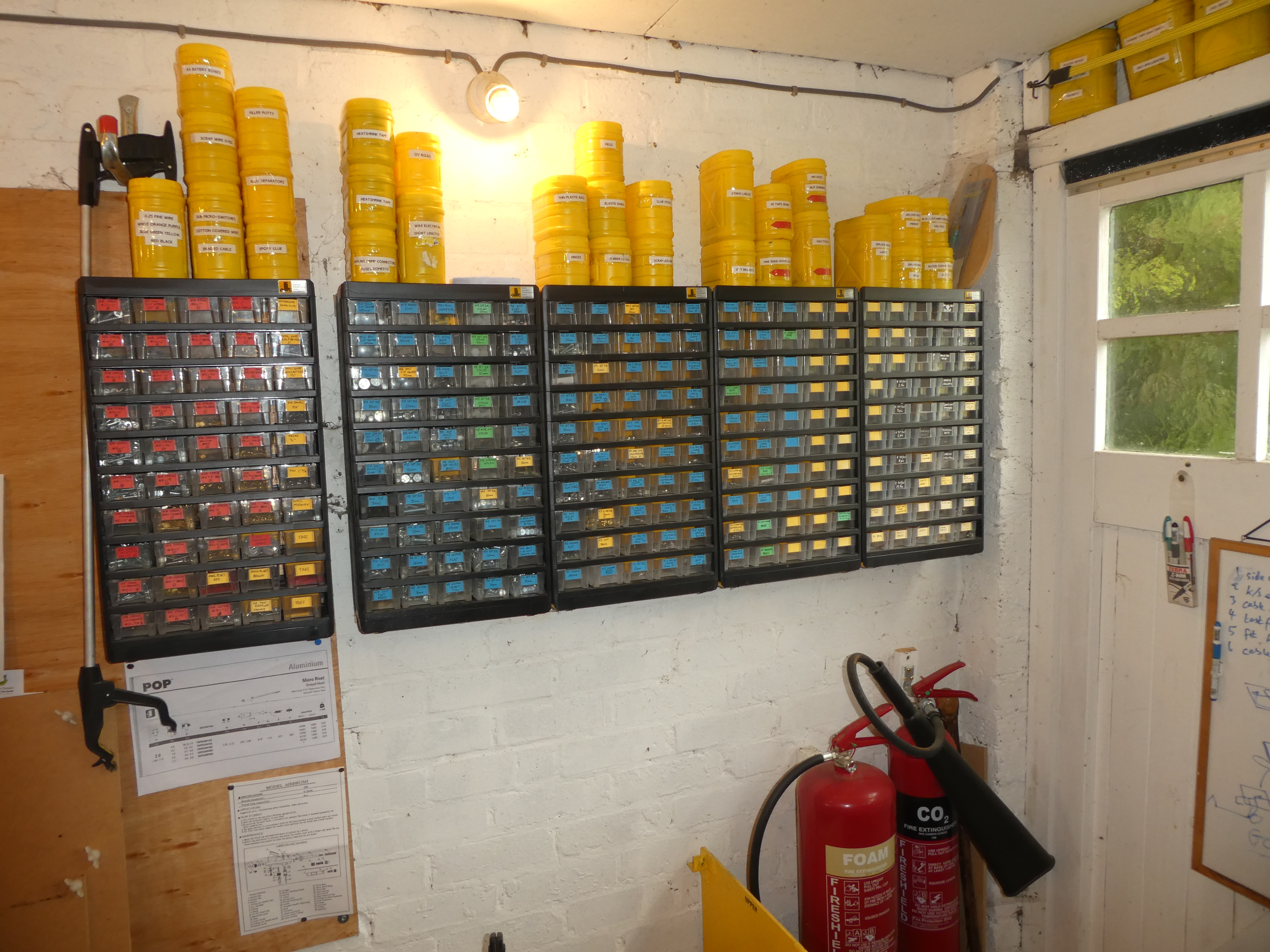
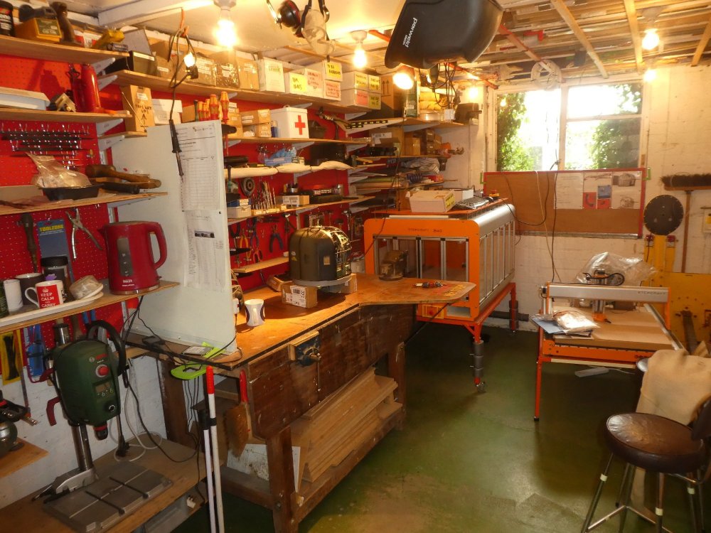
To answer some of the questions above: FME Erk, you're quite correct, my "modelling" skills, in terms of painting, weathering and so on are still fairly poor, I only recently re-learned using an airbrush after a 30 year hiatus, and am still not very competent with it. It's actually the reason I found this place, to learn more. The eventual intention is to have gunner figures within, arranged so that the FPV cameras are largely, or totally concealed within the figures when it's a static model on the flight-line, but these will "open up" in such a way to allow unimpeded filming from the cameras when recording. The front turret gunner's figurine will likely be filled with lead-shot to assist with correcting the centre of gravity, whilst the rear gunner will be hollow and as light-weight as possible. That's a long long way away though, as the FPV cameras will be the very last job on the build. Other FPV cameras will be on the pilots seat and likely another at the rear end of the raised floor above the bomb-bay, able to pan and travel along rails towards the pilots position past the navigator and wireless op crew positions. That's the plan. However there are literally decades of work ahead to build the geodetics and solve all the issues which will doubtless arise in doing so. Crazypoet, this is actually the 5th workshop I've built now, so it more or less does itself. I always have pegboard on most of the walls on one side, with vertical shelf rails between the pegboards. This gives great flexibility, as I can use the pegboard to put hooks or other fittings to hold tools, but if needbe can use that same space as regular shelf-space. So as requirements change it's easy to change the type of storage used. All walls and ceiling are painted white, with lots of light-fittings to reduce shadows being created, and powerful spot-lamp provides directable light near the bench. The floor is painted green to aid finding dropped parts. An M1 nut is about the size of this "O"! Lots of power-points finish the job. I have a couple of "rules" which help keep things organised: Virtually nothing is stored on the floor to aid keeping it clean and clear, and to mitigate fire-risks and tripping on stuff Shelving either starts deep at floor level reducing with height (for heavy bulky items) or vice versa for light bulky storage. Maximum use is made of every nook and cranny to store smaller items, see above door and ceiling. This works for me - YMMV of course, but you don't need much room to get an effective workshop up and running, but it does need designing rather than being allowed to grow organically if you see what I mean... -
Frazer Nash FN5 gun-turrets
Fidd88 replied to Fidd88's topic in LSM 1/35 and Larger Work In Progress
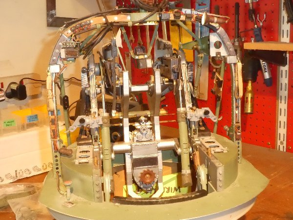
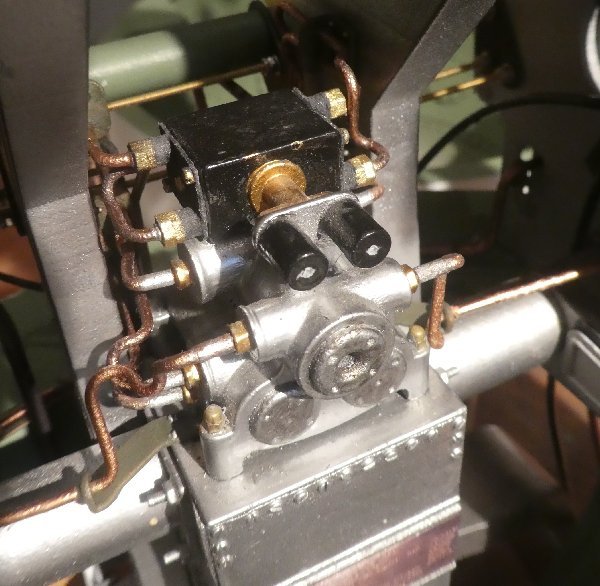
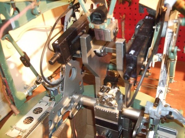
P'raps I should contact Mr Jackson at that, as the FN5a in the front Lancaster turret is essentially a truncated version of the FN5 with a slightly different cupola and doors... Nice pic of the FN car btw. Hi all, I wasn't expecting to upload a new film quite so soon but last night I connected up all the pneumatic lines to the distribution box and thence to the rams, A pair of syringes on the supply lines stand in for the yet-to-be-devised servo operated "fine tracking valve" and the "speed-limited" supply from the compressed air tank. It all worked first time, which was a great surprise and most welcome. Footage of the working rams and sight bar mechanism seemingly moved by "magic": Film of mechanism moving via pneumatics -
Frazer Nash FN5 gun-turrets
Fidd88 replied to Fidd88's topic in LSM 1/35 and Larger Work In Progress
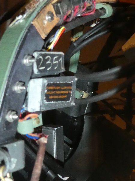
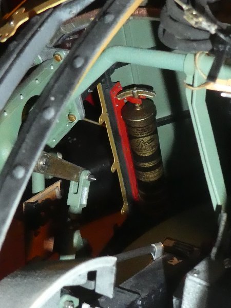
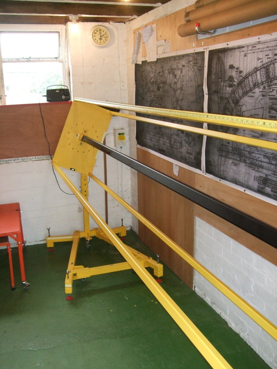
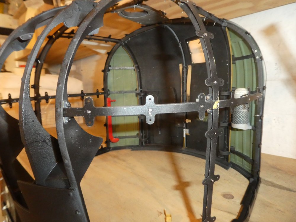
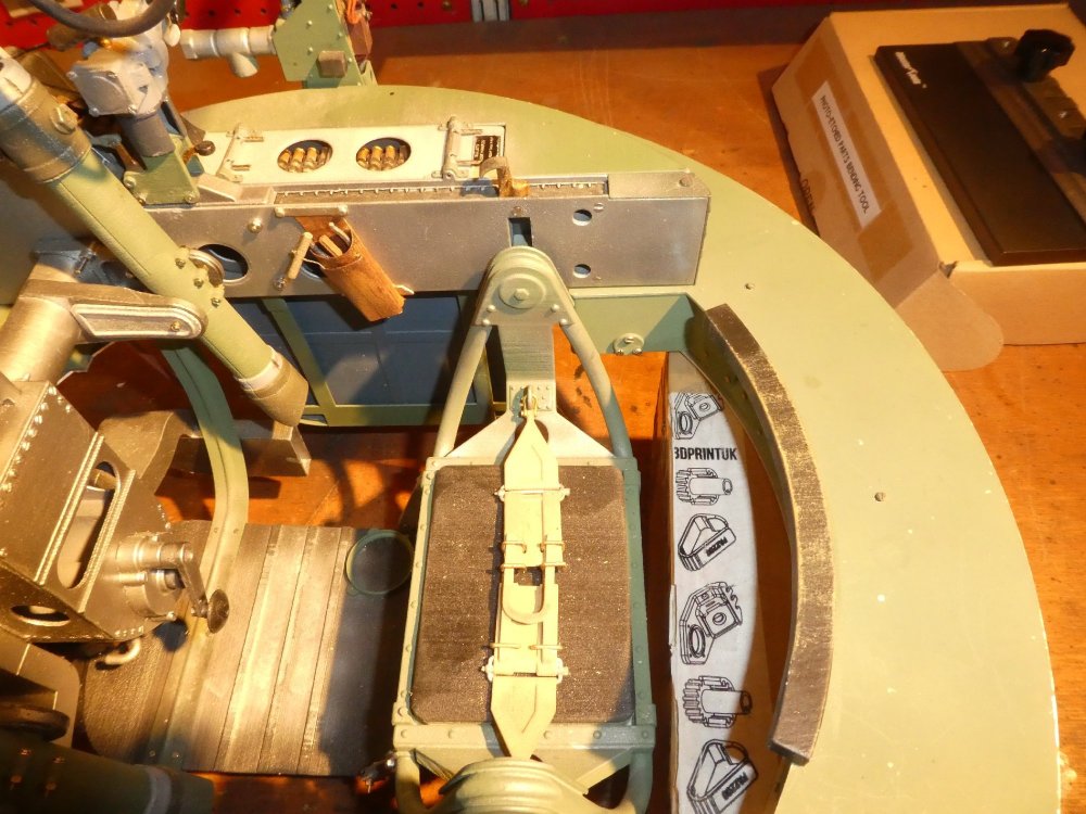
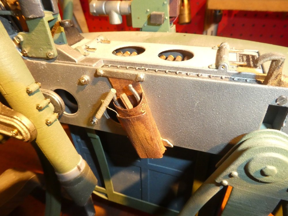
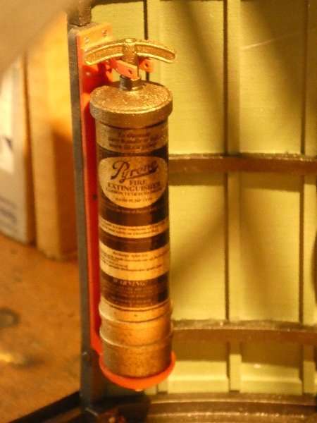
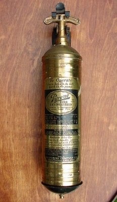
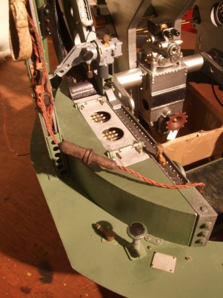
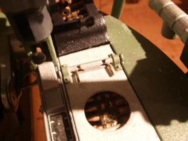
It's modeller's license on my part, possibly. I deduced that there would likely be one on inside the front turret, as the gunner couldn't escape from there without help from other aircrew, (in the air) and this took time. The rear turret, I learned after fitting it, had an extinguishers stowed on the fuselage wall immediately forward of the turret, so that one is definitely wrong. Similarly the position of the thermos-flask holder was a case of putting it where it might plausibly have been fitted. No examples survive in museums, although there are usually a raft of empty holes from which now missing fittings were once fitted. I have read that some 15 wire mesh thermos-holders were scattered throughout the Wellington, so I believe it's reasonable to assume provision was made in the turrets. I've read accounts of front-gunner drinking tea from thermos within the turret, but as to where precisely it was stored... I know not! Frankly there's buggerall room, so not that many spaces the extinguisher and thermos can fit and still have the gunner get to the controls/tanks etc. As for the extinguisher type, this I believe to be correct, although the brass-finish may have been over-painted in a duller colour. If it was, I have no scheme to work from. Something I forgot to mention about the "jig" is the function of the "cage", which is the 4 long yellow bars at the corners of the rectangular end plates (yellow). What you may not be able to see in shot is that all these cage bars have very accurately positioned metal measuring tape JB Welded to them, reading from a common datum. There's also a trolley with register marks, which can be positioned along the uppermost cage bars, on either the long or short lateral axis, to the mm. On the trolley is a laterally sliding bar, capable of being locked about 20 cm either side of the central position, and from the trolley descends a plumb-line on the same centre register lateral line. This enables me to very accurately measure linear distance anywhere on the fuselage, regardless of the jig rotation. Vertical height can also be measured, however corrections need to be applied owing to about 3/4" "sag" of the cage-bars over their length with a further correction being applied for the rotational angle of the jig. The central datum bar, to which all temporary structures defining the shape of the fuselage are bolted is 50mm square section, with radiused corners and 4mm thickness. So that doesn't perceptibly sag! (It is however bloody heavy) -
Frazer Nash FN5 gun-turrets
Fidd88 replied to Fidd88's topic in LSM 1/35 and Larger Work In Progress
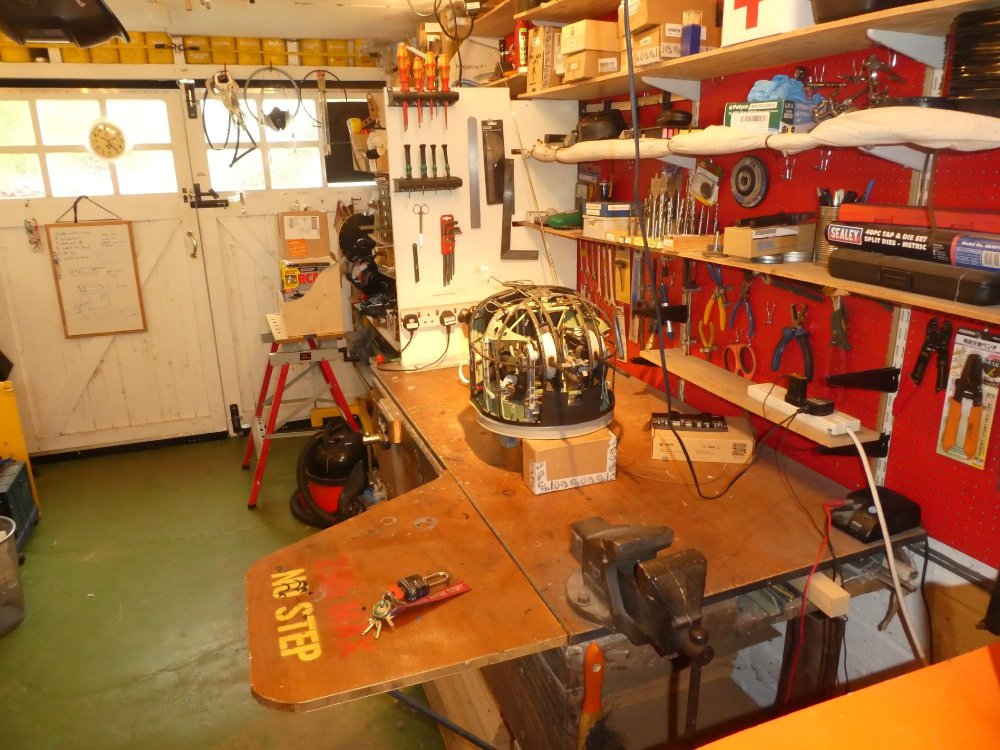
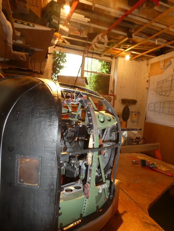
As many of the previous pictures posted are several months, or in some cases years old, I took the camera into the workshop and 'shot some more stills' (I typed more carefully this time) Apologies if one or two are a bit similar, I can't view pictures already posted when in the workshop easily. I've made the max dimension 2000 pixels, I hope this isn't too large for here? My little you-tube channel documenting the turret builds is here: Fidd88 I expect that's about it for the foreseeable until the windows are done, or the pneumatic system is up and running. Happy to answer any questions people might have regarding the limits of SLS nylon printing, or on the subject of gun-turrets. If I can help with CAD drawings for your own projects, anyone, please just ask. In the picture below, the battens on the roof are my patent storage. The natural wooden battens are screwed to joists at every joist. The red ones only span 1 pair of joist each, and have a screw only on one allowing them pivot parallel to the joist for getting long objects up there. Home-made fittings with a detent position prevent them moving and dropping stuff on my nut!


-
Frazer Nash FN5 gun-turrets
Fidd88 replied to Fidd88's topic in LSM 1/35 and Larger Work In Progress
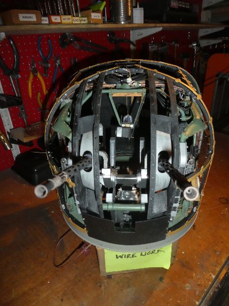
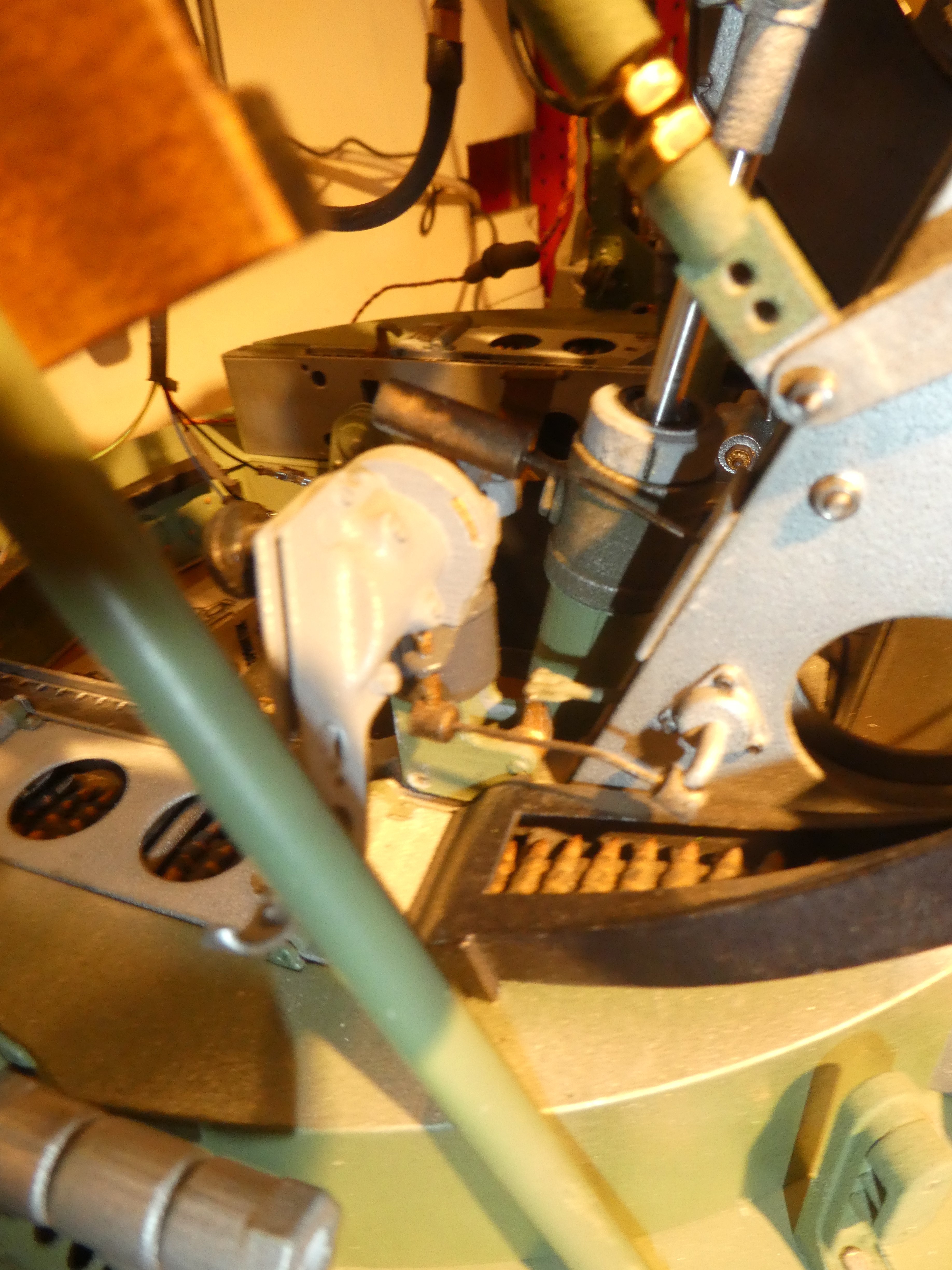
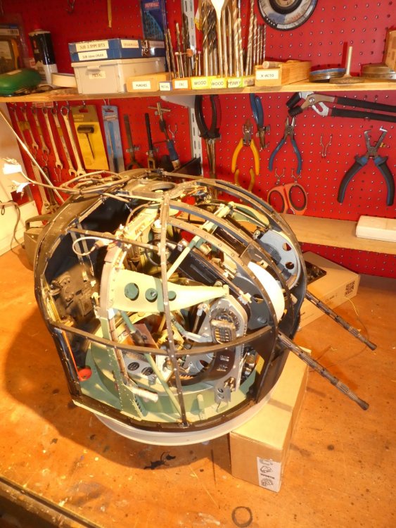
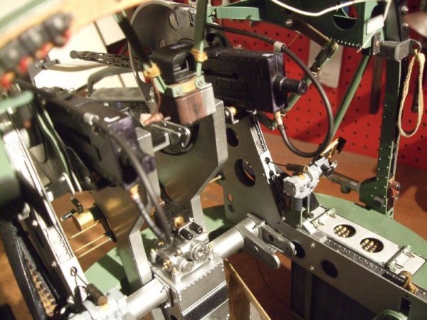
Hehe. the funny thing is I havn't actually added many of the detail parts yet, mainly as their too fragile to stand all the wrangling that's done fitting other more hefty parts. There's a huge amount of hydraulic pipes, hoses, brackets and general plumbing to add shortly. American turrets were developed from British examples sent over in 1941 by Boulton Paul and Frazer-Nash, and subsequent American refinements were either all electric or electro-hydraulic as per Boulton Paul designs, whereby all the hydraulics were in the turret, which made for less leak-prone designs. This being a Frazer-Nash turret, there's pipes bleedin' everywhere! I'll take some more up to date shots tomorrow and post back. Thanks lads, -
Frazer Nash FN5 gun-turrets
Fidd88 replied to Fidd88's topic in LSM 1/35 and Larger Work In Progress
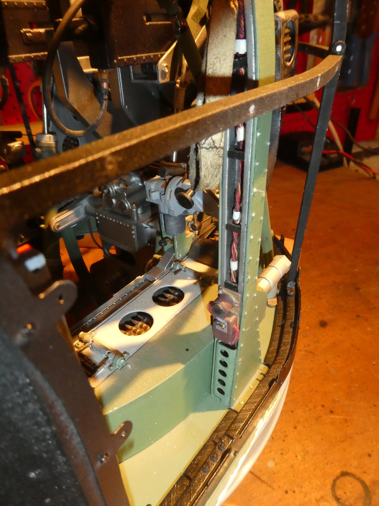
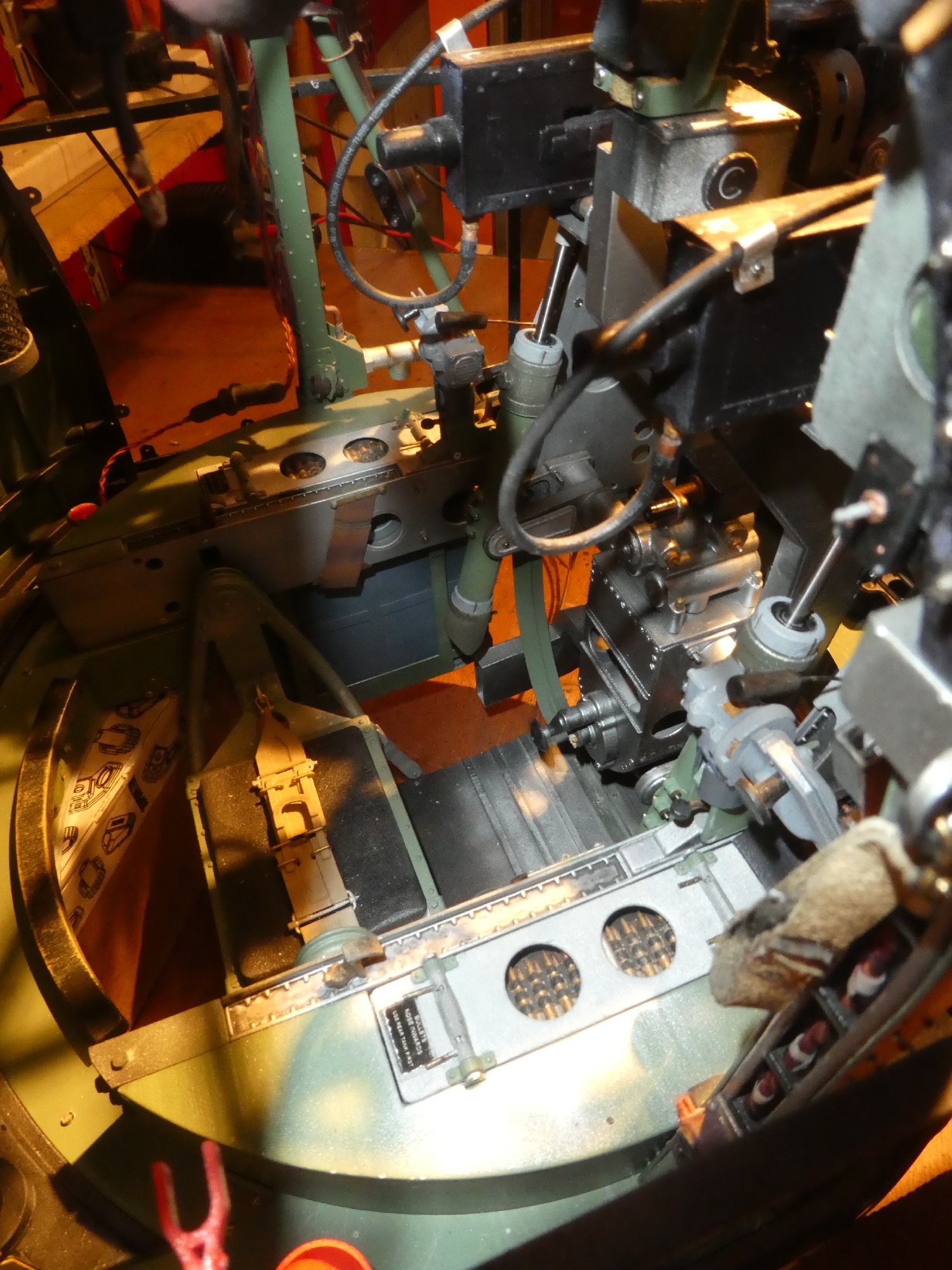
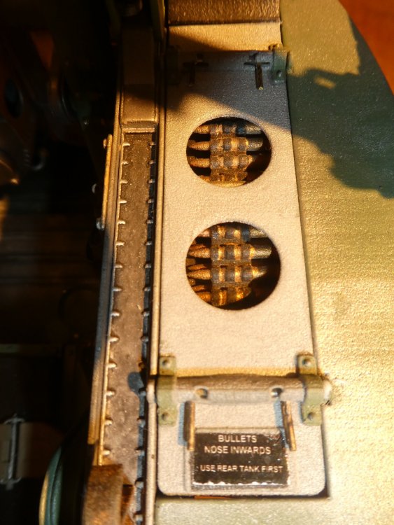
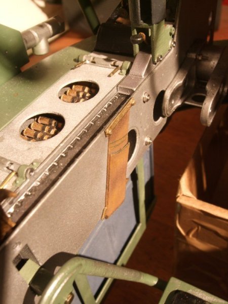
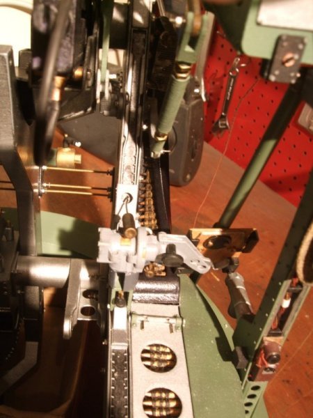
Thanks for the welcome chaps. Really the whole turret thing has been dictated by what I could actually draw in CAD using Autodesk Fusion 360, and what details would resolve in SLS nylon. So for example it took me over 60 attempts to correctly draw the curved and twisted ammunition feeds (I was bloody well "curved and twisted" by the time I achieved them!) The green metal pieces that connect the arch of the turret are known as chordal brace stiffeners, and I drew them over 40 times, from scratch. So it's really more being stubborn and always seeking to improve the drawings than actual model-building talent. That's my tuppence worth! Research was also a problem, as as far I can tell, there are no extant technical drawings, and the illustrations about are generally wrong in places. Hence the over 1200 revisions to the main assembly drawing, and around the same number of individual component drawings. Currently there is no aircraft model to attach them to, although I have built a home-made jig on which the fuselage, inner and outer wings, floating main-spar, tail and fin can be assembled. The finished aircraft will be just over 4.5m long including the turrets iirc. Attached are pictures of the jig (yellow) shewing the central black bar on the aircraft datum, and the "cage" which rotates and can be locked off though 360 degrees of rotation at 16 degree intervals iirc. The idea here was to make assembling the port or starboard side as easy as the other, without having to drag the whole thing out of what us a very small workshop! There's also an (old) picture of the two main join types in the Wellington's geodetics, which have had to change slightly to ward off metal-fatigue issues with the reduction in scale. Also pictured are the individual .303 rounds of my own design, which fitted together into a tapered slot of the adjoining round. This enabled "belts" to be formed, which would curve and twist evenly around the chutes, before being glued in situ. It was that or to try and construct a curved and twisted belt in CAD! No THANKYOU! (with feeling) The final picture is a method of making geodetic channels out of carbon-fibre, using extruded silicone moulds, the idea being to place these over a former to go hard in situ before being demoulded. Amazingly it did work, with weight of 33mm to the gramme and was very strong to shear-loads, but rather less so to tortional ones. The failure rate and time and money involved really put the tin-lid on it, although I may use it for short and highly curved ones. At the moment I'm fighting with the clips which go on the back of the brass strips, sandwiching the windows, and recommissioning the CNC router to make the plug for said windows. Both are a little frustrating just now! I daresay you have people here who can draw up parts, for 3d printing, but please sing-out if I can be of help in that regard.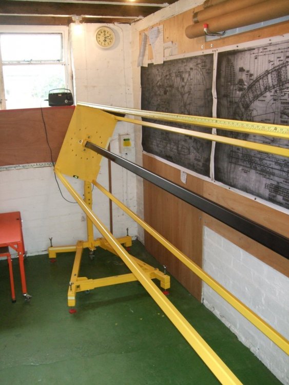
-
Frazer Nash FN5 gun-turrets
Fidd88 replied to Fidd88's topic in LSM 1/35 and Larger Work In Progress
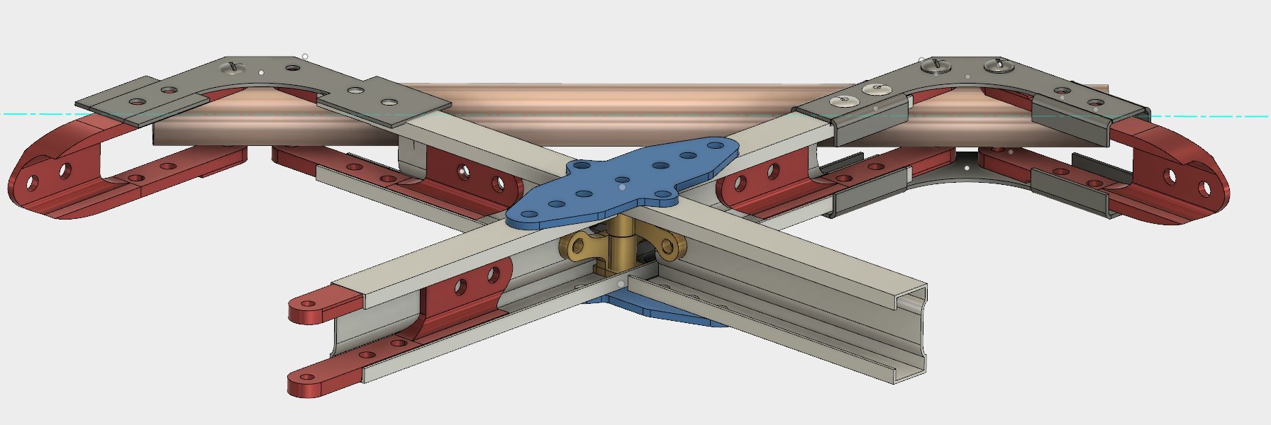
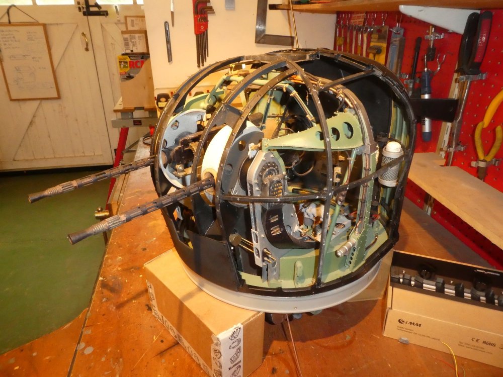
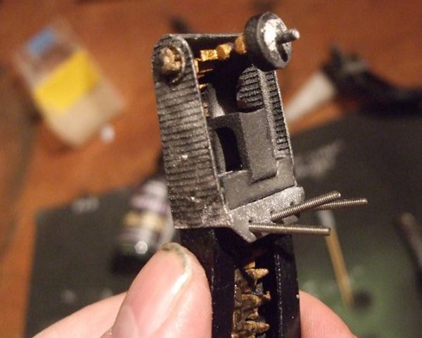
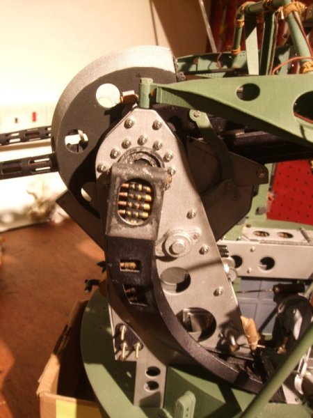
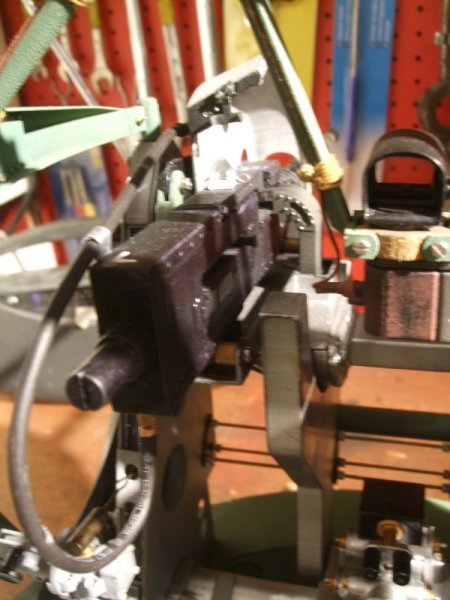
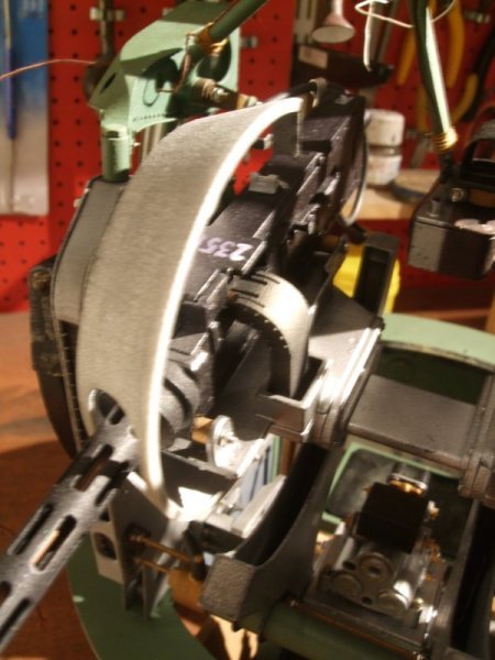
It's approximately 1:4.5 scale. The scale being determined by two things, the relatively small choice of 9 cylinder radials available to power it, and how small one can make the internal fittings of the geodetics which enable two geodetic members to cross each other but remain locked in relation to each other. Incidentally, I love your Rescue Lance! I attach a few more pictures of the mechanism within the turrets, and one of a similar actual one in the mid-war onwards all black scheme. likewise the 2nd shot of the extinguisher is for comparison. I had a lot of fun making my own transfers (decals).

-
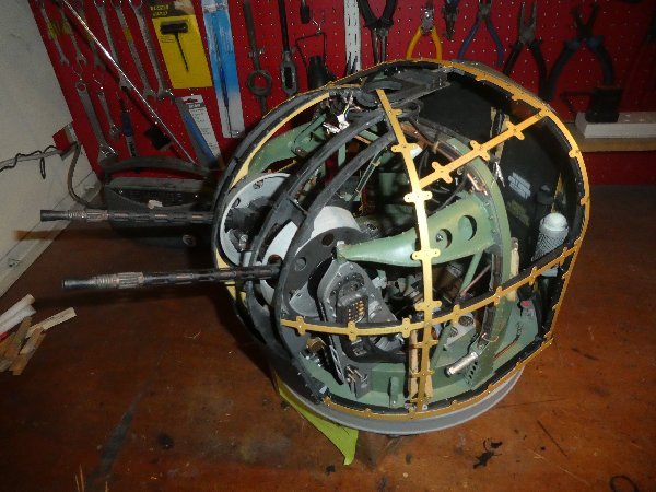
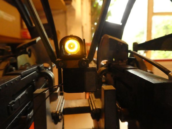
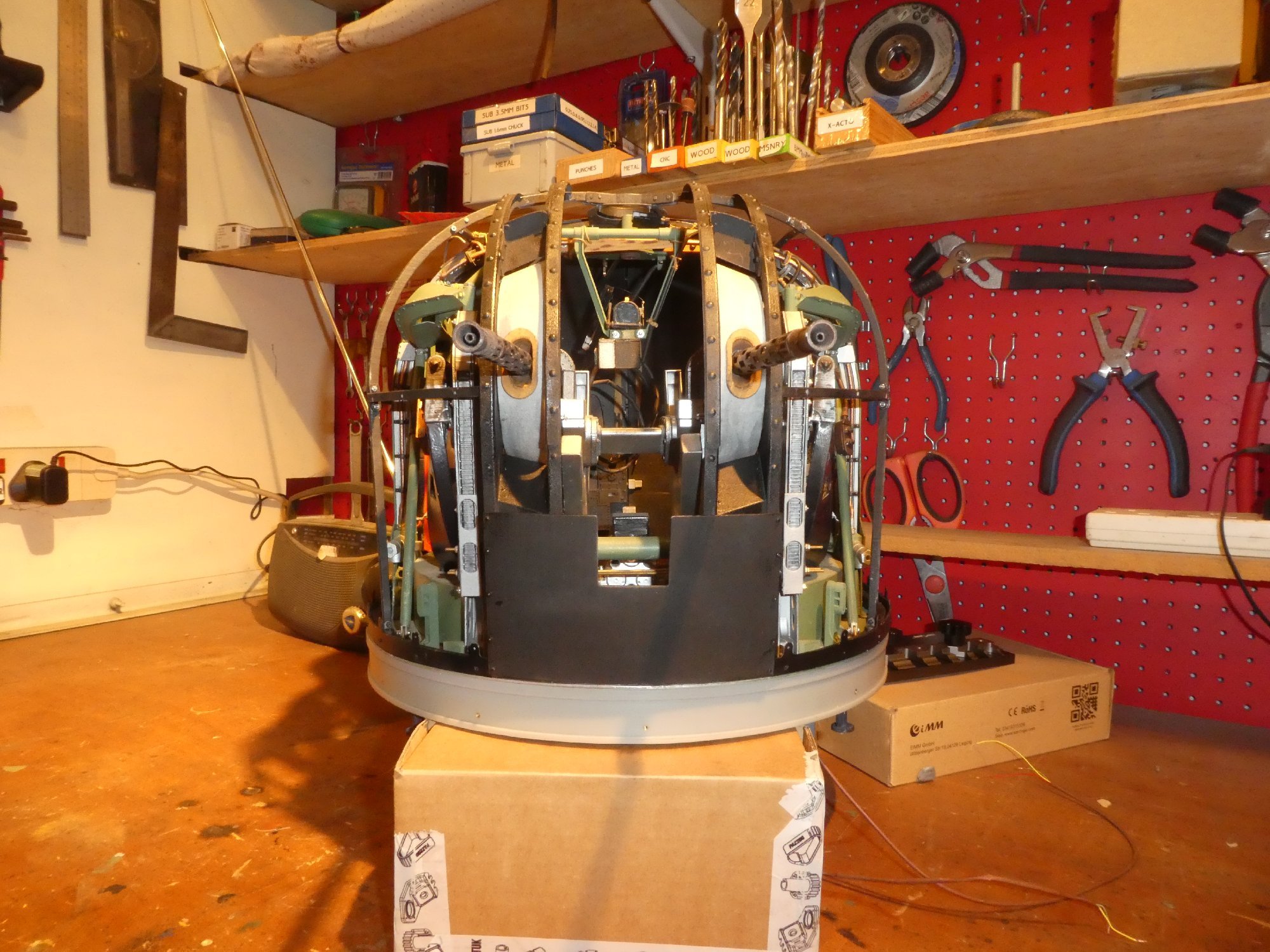
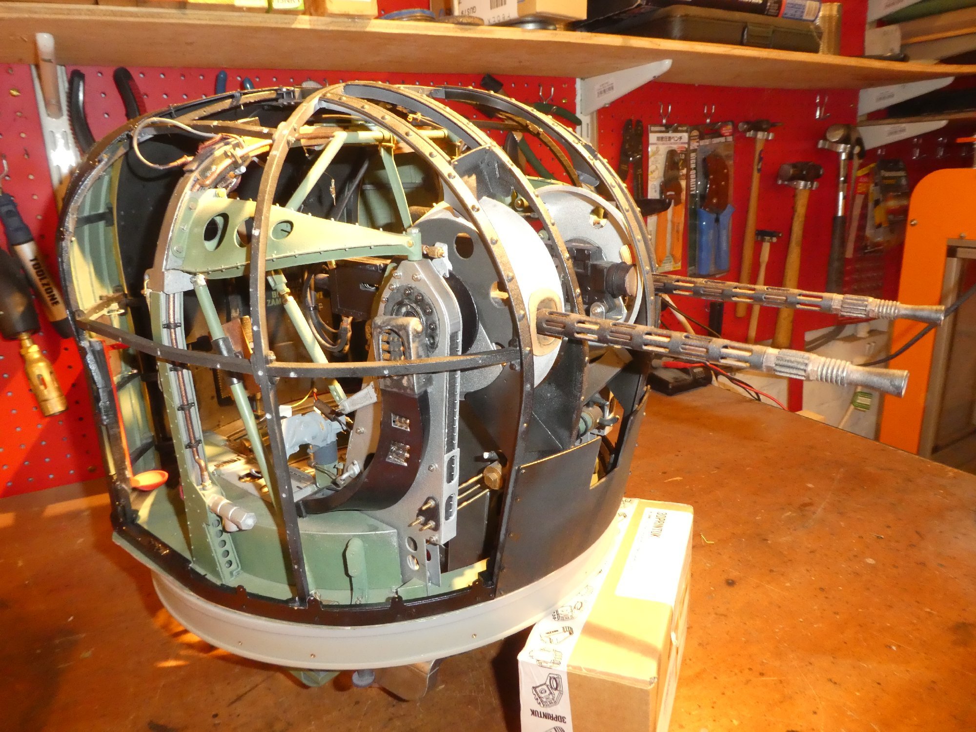
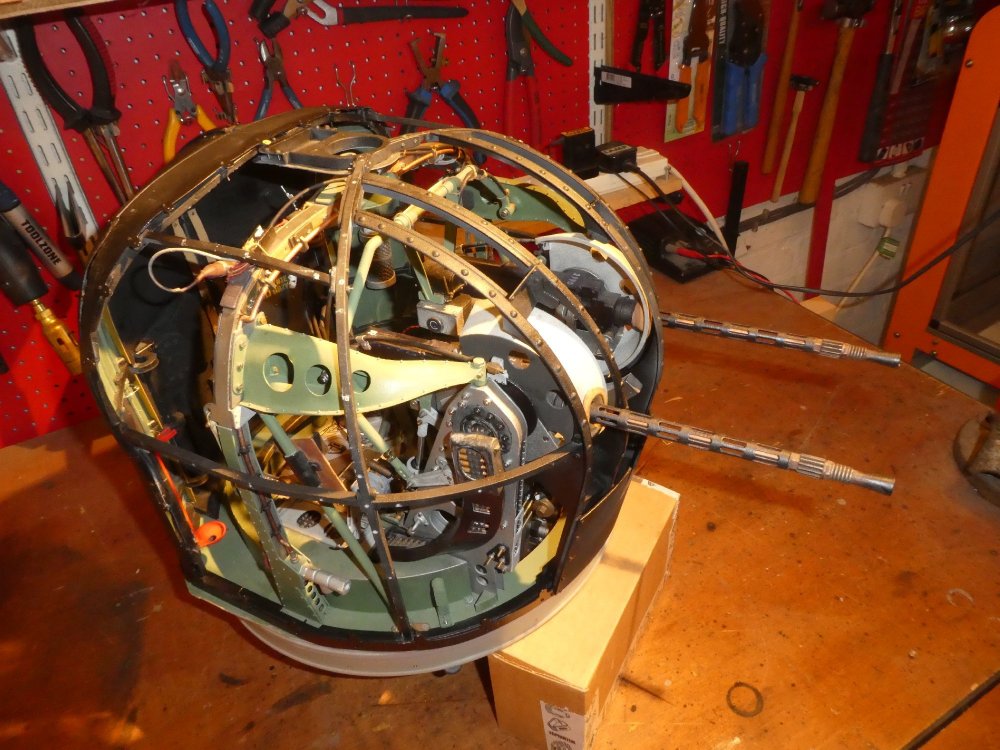
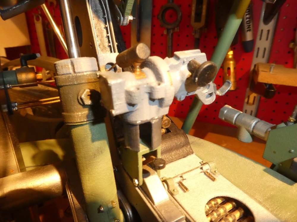
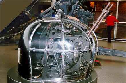
Hi all, As it's a bit of an unusual modelling subject, I thought some might be interested in the pair of FN5's I'm building for a very large RC Wellington Mk 1c, in the colours (eventually) of one of the Polish RAF squadrons operating the type in 1941. The turrets will have "FPV" cameras installed eventually, allowing the rear turret to track targets through a working reflector gunsight (built in collaboration with Tim Noack) whilst the front turret will have a more general view that is pan/tiltable independent of the turret movement. The turrets feature working pneumatic rams elevating and depressing the gun cradle, with all the mechanical linkages that keep the gun-sight parallel to the guns working as per the full-size turret. Virtually no glue has been used anywhere, with most parts 3d printed in SLS Nylon, then holes drilled and tapped before finally being screwed together, usually with M1 machine-screws, nuts and washers. The turret have extensive lighting, an overhead lamp, spot-lamp, amber warning light, and 3 coloured Bendix lamps, all of which are either "grain or rice" or "grain of wheat" light-bulbs. The gun-sight has an LED, and produces an auto-dimming glowing reticule in correct for the era, which at the correct focal length us the correct size. All function. From initial research to where the builds are now has taken three and a half years during which I've taught myself CAD, soldering, and using an airbrush, as well as all the engineering side to have the moving parts, often separated by gaps of only 0.1mm, work as intended. If you search youtube for Fidd88 you can see the videos that documented the build over the last 13 months or so. I should point out that I'd never used a cine camera or looked at youtube when I started, so some of them are a bit dull and repetitive, I'm not what you'd call a "talented film-maker"! I'd recommend starting with the most recent films and working back. All of the parts have been 3d printed from my own CAD drawings. There are a few known errors in dimensions, but as there are no extant technical drawings to work from the whole thing has been reverse-engineered from photographs. No two museum turrets being the same, this was a difficult exercise as you may imagine! It's as accurate as I could make it however. Anyway, here are a few pictures. If any of you have comments or questions, please feel free to ask, and I'll do my best to explain. There's still a lot to do: Fabrication of initial plug to make mould to cast positive over-which hot Perspex is pulled to make cupola windows. Bolting window panels to sub-frame, attachment of cupola Plumbing of pneumatics to drive elevation and depression of gun-cradles Camouflage of same to resemble hydraulic pipes Addition of plethora of cosmetic hydraulic pipework Weathering, dirtying and so on of entire turret paintwork. When all services are proved, lock-tighting of all nuts. I hope you find this interesting, if not up the amazing standards of modelling here! The eventual intention is to build the Wellington 1c in extruded alloy channel to form a geodetic construction as per the original aircraft.