Fidd88
-
Posts
196 -
Joined
-
Last visited
Content Type
Profiles
Forums
Events
Gallery
Everything posted by Fidd88
-

What do you consider is the meanest tank in history?
Fidd88 replied to Sir Desmond Glazebrook's topic in General Discussion
To answer the question fairly, the measure has to be up against its contemporaries, rather than simply measured against the most modern of tanks. By this metric, I'd have to go with the original MK IV male of WW1, simply because it had no contemporaries to speak of, and whole battalions of Fritz routed at their approach, or, the immediate post war Centurion, which had I think the perfect balance of firepower, armour, speed and excellent design. If only it'd been available 3 years earlier! There's a few I'd exclude from the list, the Abrahms. Tiger I for openers. The Abrahms because although very quick and capable, absolutely requires both total air-superiority and lack of insurgency along the supply lines to keep a large formation of them moving, so much fuel does it use. Against the Russians or Chinese neither of these pre-requirements can be gaurenteed. The Tiger 1 because although it instilled fear, it was hideously unreliable and expensive, hard to recover far more were lost due being abandoned for want of time to repair than were knocked out. It failed utterly, as a strategic vehicle, and similar vanity projects sapped German war-production. -
Frazer Nash FN5 gun-turrets
Fidd88 replied to Fidd88's topic in LSM 1/35 and Larger Work In Progress
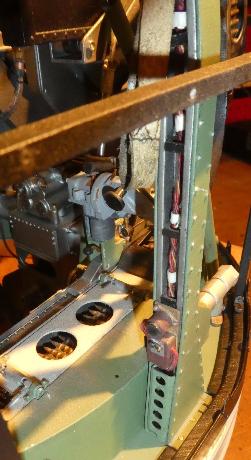
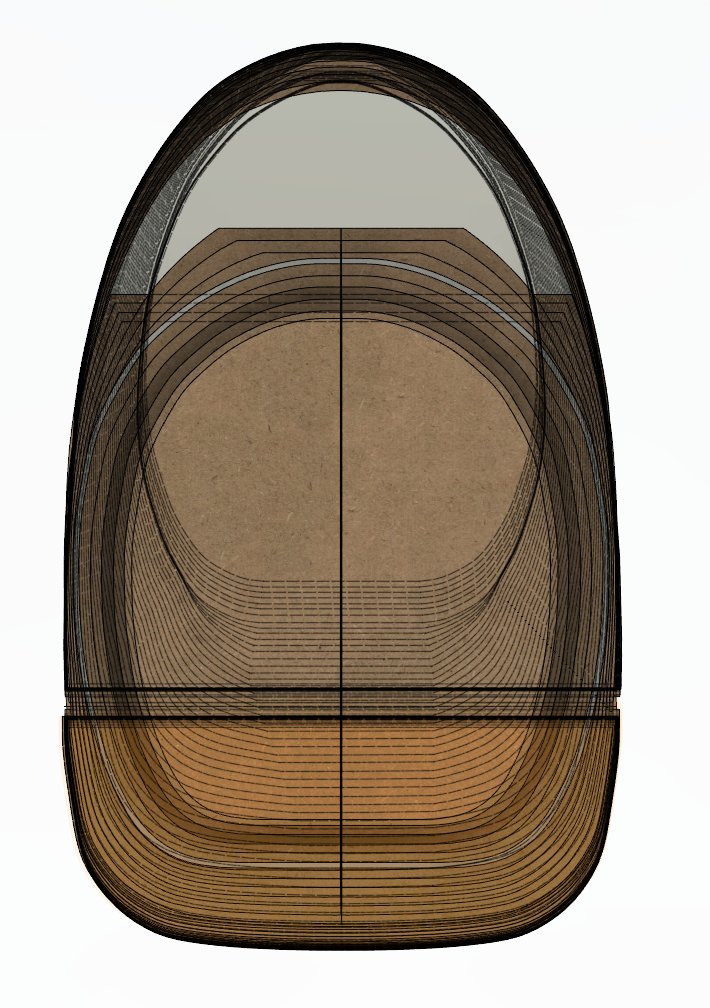
I'm glad you enjoy it, but what don't you follow? 4 Years ago I was still doing drawings on a drawing-board with sharp pencils! Pretty much everything I'm doing now has been learned in the interim, the great majority in the first 18 months. Learning CAD, especially in Autodesk Fusion 360 is a doddle for most shapes. As I think I said upthread somewhere, the only area I needed to seek help was in constructing complex curvatures, ie shapes like the one above where it curves in two or more directions. 3d printing is a complete doddle although with experience you'd discover the limitations of different sizes of part, type of plastic and method of deposition. This is nothing the great majority of you couldn't pick up in a few weeks of applied practice, and a few months to get reasonably efficient with it. In a way, I'm surprised the scratch-building modellers aren't making more use of it to produce parts for models where the aftermarket kit parts don't carry the part in the scale you want, or simply don't make them. CAD/3d printing is a seriously powerful tool. This evening I came across a rather useful looking process for polishing 3d printed ABS called "Cold Acetone vapour polishing" which gets rid of the great majority of layer-lines inherent in 3d printed ABS. Once that's done, the only issue remaining is to prevent the hot Perspex - or PETG etc - from sticking to the ABS when the frame of hot plastic is vac-formed over the mould. As this develops I'll let you all know, as the principles hold true if you're making a 1:4 scale turret cupola, or a 1:72nd fighter canopy from scratch... Attached is a picture of the underside of the two part (now separated) mould above. The hexagons continue to the underside of the shell, and I plan to fill the voids therein with expanding foam, to help make the relatively thin working part of the mould more or less incompressible when the hot plastic is vac-formed downwards onto the mould. That's the plan anyway! The other wrinkle, if you'll pardon the phrase, is that although I've done the CAD drawings for the side and overhead window panels, and these are slightly complex curves, I've decided to try and fit flat sheet and bolt it all in place before heating it with a hair-dryer. If I'm lucky this will allow the sheet to develop the compound curves needed without the expense of a 2nd mould. Got to be worth a try!
-
Frazer Nash FN5 gun-turrets
Fidd88 replied to Fidd88's topic in LSM 1/35 and Larger Work In Progress
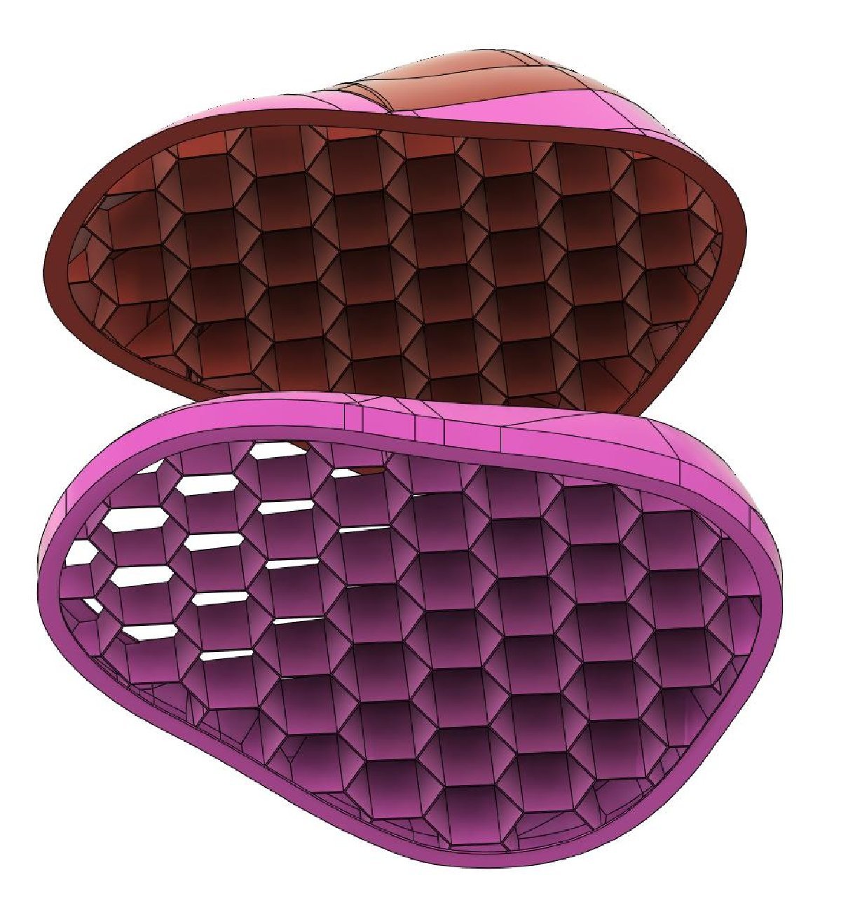
So things have come to a bit of a grinding halt of late as I investigated several means of fabricating the mould required to vac form the curved front cupola windows. I looked at CMC cut MDF/micro-balloons, but it was a great deal of work, and when costed out, getting the mould 3d printed in ABS via a Chinese service came out only slightly dearer than the MDF route, possibly cheaper once all the required resin and microballoons were taken into account. I'll need to treat the ABS with some liquid plastic or filler to bring it up to a highly polished and thermally stable finish for vac forming. I'll let you know how that goes. Below is a picture of the two-part mould, the red portion being the area I need, the pink the surround. The split is low down away from the red, so no seam lines. The two part approach was required for cost purposes. Underneath is a honeycomb structure which I'll fill with expanding foam, to help make the mould incompressible as it's vac-formed.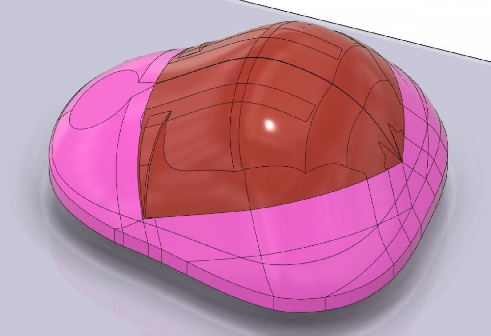
-
'Skeletal' Fokker D.VII
Fidd88 replied to sandbagger's topic in LSM 1/32 and Larger Aircraft Ready for Inspection
Just beautiful work. Thanks for sharing it! -
Hasegawa P-40E.
Fidd88 replied to Sir Desmond Glazebrook's topic in LSM 1/35 and Larger Work In Progress
I'm so sorry to read this, was really enjoyable watching this build, but am happy you're taking something positive from it. May I ask, how come your hands were numb? Your models are all the more astonishing if that's a permament condition... There was a crash-landed P40 discovered in the Egyptian Desert a couple of years back, which I've often thought would make an excellent diorama...

-
1/24 scale DHC-2 Beaver actual build
Fidd88 replied to CrankyCrafstman's topic in LSM 1/35 and Larger Work In Progress
Considering the scale at which you're working, and the fineness of some of the parts, in my experience of 3d printing in SLS Nylon, I think you might be better off printing it in one piece, as the very thin components will at least have some support. On the other hand, depending on the interval at scale, the cooling fins on the heads and cylinders will be very difficult to render, and if they do, will likely be filled with powder, requiring some very gentle old-toothbrush work to bring out. In that situation, the flat strips on the front of the engine may be in the way... -
Thanks, but I just wanted to pass on the wheeze of using silk-covered wire and hand dyeing it, which probably has applications for many of you. I was going to paint the wires, (as I also had some of the plastic braided nylon as above) but then twigged the silk would take dye. The best bit Is that you can dye yards and yards of it, and then when dry, wind it onto a stick for ongoing use or to let someone else have some. The silk covered wire can also be braided, which is how #1 daughter made the RT leads on the turret. FWIW. Amazing work on the Mossie. (which is probably what we should be focussing on here?)
-
(some snippage of quoted text) You may be interested in a wheeze I came across doing the "period electrical wiring" on my FN5 turrets. You can get braided silk-covered fine wire, and the silk, being a natural fibre can be dyed with fabric dyes to match the colours found in original wiring looms. I used black, red, a dull light green and brown. The vertical twisted wiring "loom" in the channel was done with this method.

-
Frazer Nash FN5 gun-turrets
Fidd88 replied to Fidd88's topic in LSM 1/35 and Larger Work In Progress
Good Lord no, I'm just a chap in a shed, and havn't made a model otherwise for nearly 35 years, when I last made an Airfix kit! Most of the skills needed I picked up over the course of the last 4 years. If there's interest, I may look into seeing if it can be produced as the basis for a kit by Airfix or the like. It'd be wonderful to get commissions to build or just design this sort of thing though, but I think I need to improve the design to make it easier to build. The turrets are my "middle-aged crisis" or whatever they call it. Some buy Ferrari's, I built turrets, which some wag called "turrets syndrome"! -
Frazer Nash FN5 gun-turrets
Fidd88 replied to Fidd88's topic in LSM 1/35 and Larger Work In Progress
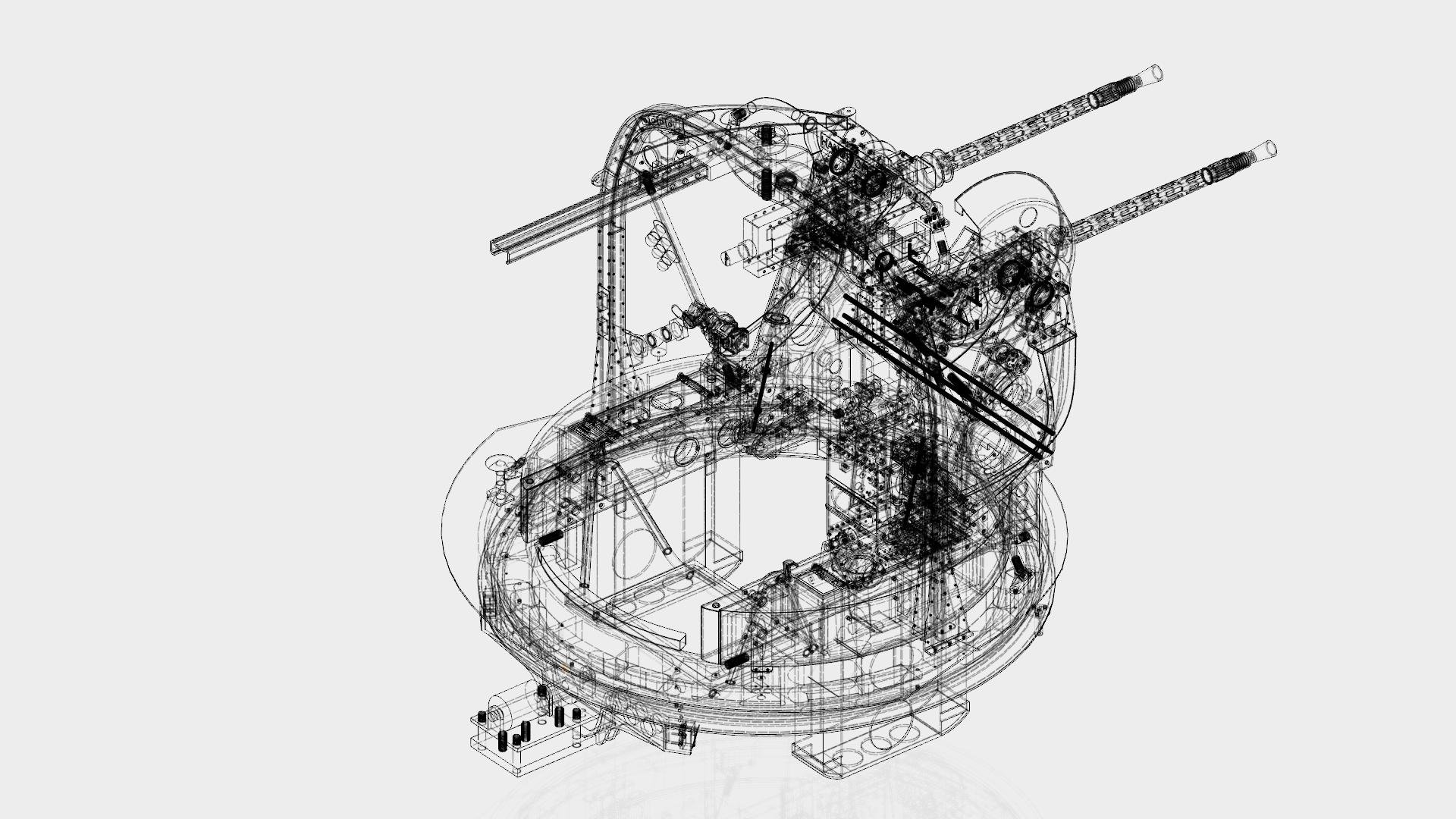
Thanks lads. Although the turrets took the best part of 4 years to build, this included tons of research, learning CAD, and endless revisions of the initial design, followed by many many revisions and reprints of individual parts where needed. During this time I also spent a lot of time on initial drawings of the fuselage. Now that the design is finalised, I estimate I could build, both turrets from scratch, in circa 4 months for the pair, which is not excessive when compared to the time expended on similarly sized RC models, whatever the construction technique. The same will apply to the airframe, it's the setting-up of the jig, paths of longerons and cutting the MDF patterns for curving each geodetic member that takes the time. Once the actual geodetic fabrication commences, after prototype test pieces are made to prove the build-method, then I'm expecting the construction to be fairly rapid. It's the preparation that takes all the time. So were the aircraft lost, then again, finance permitting, I'd expect the airframe to be completely rebuildable within 2-3 years. If the design is proven safe, and reliable, then I'd be in a position to start building a second airframe , and/or turrets in fairly short order. The original design-brief I set out was to be able to film with FPV cameras from within the two turrets, from the pilots position, and from a position roughly atop the aperture for the old ventral turret, ie able to view the length of the fuselage fore or aft, as well as through the long side windows. Secondly to replicate the geodetics in alloy at scale, and to have no visible servos or uncamouflaged electronics or wiring within the turrets or fuselage to detract from the fuselage interior view. The ability to get good in-flight footage from within the fuselage really drove everything from the construction techniques to the turret complexities, and of course it was much more interesting to design and build these as fully functioning operable turrets, than the usual two sticks of black-painted balsa poked through a simple cupola shape in clear plastic... -
Frazer Nash FN5 gun-turrets
Fidd88 replied to Fidd88's topic in LSM 1/35 and Larger Work In Progress
#1 daughter and I were invited to a commemorative event at the Brooklands Museum in Surrey, to exhibit the now largely complete turrrets. The event marked the 80th anniversary of the "Battle of the Heligoland Bight" where 24 Wellingtons were despatched in daylight on an armed reconnaissance raid of Jerry warships in the area off Wilhelmshaven. Half the attacking force were lost on the way back, or crashed in England. This fairly definitively spelt the death-knell of the notion that the "bomber would always get through", despite new-fangled hydraulic turrets, and the RAF then adopted night-bombing until early '45. ('44 in France). It was also this experience which made us all think the B17 daylight bombing was going to be a very bloody business. Anyway, whilst we were there we got interviewed by the chap who makes most or all of the video for the museum, and he's just sent me the link: https://vimeo.com/380993532 Rather better than my efforts! Fidd -
Frazer Nash FN5 gun-turrets
Fidd88 replied to Fidd88's topic in LSM 1/35 and Larger Work In Progress
Not a problem. A little off-topic variation makes for lots of interesting stuff! I am completely with you about the loss of this history. As an ex (civilian) flying instructor, my personal pet-hate is the way airfields are now being renamed to lend a false sense of proximity to the nearest - but yet not close - city. Manston becoming "Kent International Airport" and "Shoreham" being "Brighton Airport" (until they have a crash, when it's "Shoreham" again!), "Kidlington" becoming "Oxford Airport" and so on ad nauseam. To me, these airfield names evoke the smell of 100 octane and the whistle of opened canvas gun-ports, the line of a Spit's wing, the tick of a cooling Merlin, and the incredible sacrifices and courage of the men and women at these places 80 years ago. To have some ignorant bloody self-serving councilman "rechristen" them to inflate his "profile" in his town makes me bloody cross. As for developers building housing estates on them..... I cannot safely comment on a moderated forum and give full vent to my feelings on the subject! -
Frazer Nash FN5 gun-turrets
Fidd88 replied to Fidd88's topic in LSM 1/35 and Larger Work In Progress
You probably can't throw a stick In Lincolnshire without it landing within two miles of an ex Wimpy field! -
Frazer Nash FN5 gun-turrets
Fidd88 replied to Fidd88's topic in LSM 1/35 and Larger Work In Progress
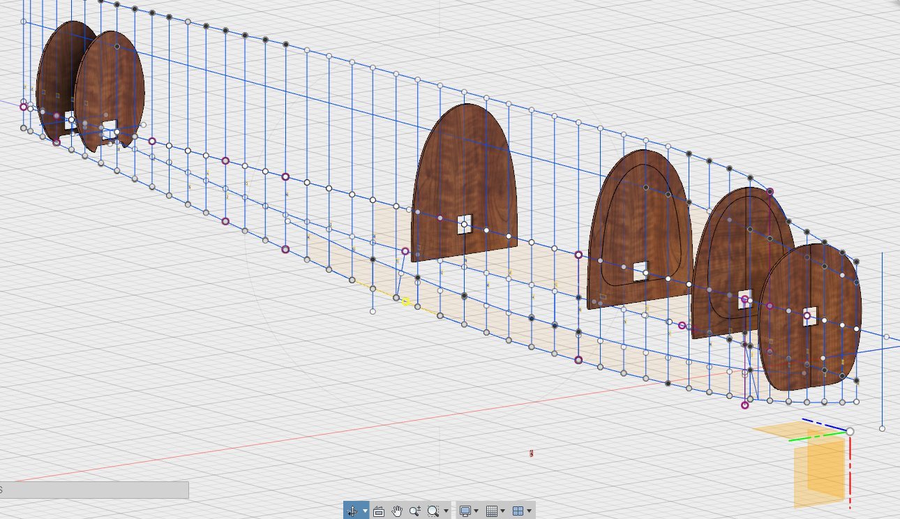
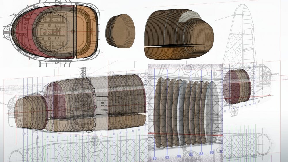
This next image shews the method of interpolation. The lines (by inspection) represent the paths of the longerons, which could be defined in space both laterally and longitudinally. Wherever these were plotted, these formed a point to use the "spline" command in fusion 360, with other points at top and bottom. The ratios between these were kept constant as the fuselage tapered iirc which helped smoothly transition the shapes. Probably, accidentally, what you call "parametrics"? A similar plan drawing operated in the same way. The results aren't perfect, but they're pretty close, in terms of constructing the 3d shape from 2d drawings. The picture was named "loo-seats" as my wife said that's what I'd drawn when shown the initial drawing!
-
Frazer Nash FN5 gun-turrets
Fidd88 replied to Fidd88's topic in LSM 1/35 and Larger Work In Progress
Thanks, I may. Attached is a picture of the fuselage from aft. The tail-end is still not quite right, as I need the dimensions of the 90 frame, but it's getting closer all the time. The wishbone frames need trimming too - they're poking out at the bottom currently!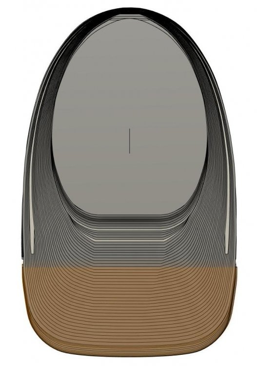
-
Frazer Nash FN5 gun-turrets
Fidd88 replied to Fidd88's topic in LSM 1/35 and Larger Work In Progress
Urgh. I'm not surprised most "free" 3d software is worse than useless. Fusion 360, which is free for non-commercial use, was the first one I found that was decent. I must have tried 10 or so free ones before that, all were as much use as a chocolate tea-pot! -
Frazer Nash FN5 gun-turrets
Fidd88 replied to Fidd88's topic in LSM 1/35 and Larger Work In Progress
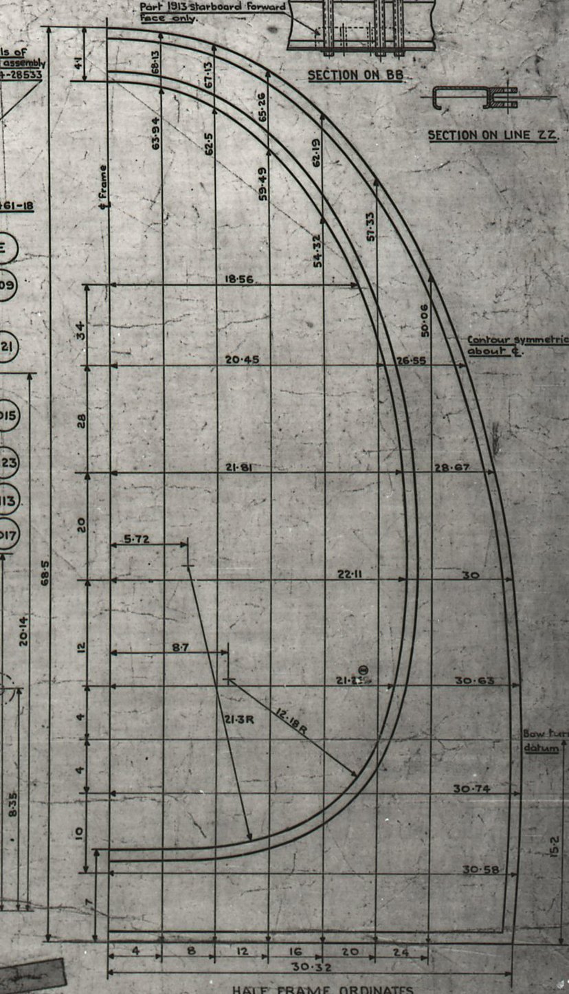
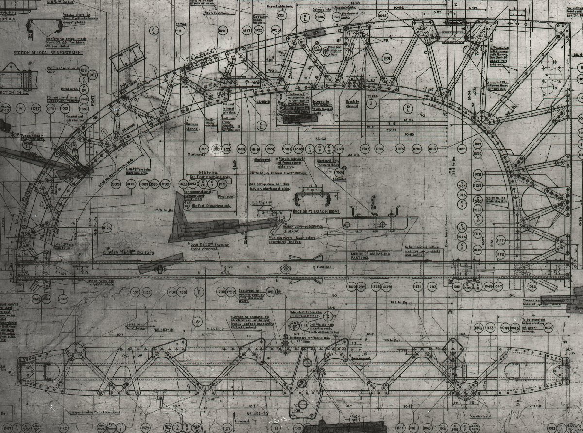
I was fortunate to have access to the microfilm archives at Brooklands, so I had the assembly drawings for the "five and half", "twelve and a half", "twenty-two and a half", and "fifty", and "eighty five" frames bulkhead drawings. But not the 90 frame, nor the "wishbone" pair of frames which supported the deleted ventral turret. So most of the internal shapes I knew, and it was a matter of interpolating between them to attain smooth curvatures without any "lumps". In my drawings the frames coloured silver relate (in shape) to the known dimensioned drawings, the wooden shapes being interpolated values between them which correspond to the known vertical and lateral extents of each shape at each interval. So, these shapes replicate - as far as I can achieve, the space within the geodetic channels on the Wellington. They're in two parts because the floor over bomb-bay is plywood covered geodetic channel. On the model, the geodetic channel is roughly 1/2" on the long axis of the rectangular cross-section, and about 1/4" deep. I had to vary from the scale size owing to potential difficulties getting a rivet-gun into some of the areas required, and the need to thicken the metal over scale to reduce the risks of metal-fatigue. Once the turrets are finished, the next project is to source some extrusion, some prototype alloy shear and gusset fittings, and some more metalwork tools, before building prototype structures - most likely a ball and a short length of cylinder to fatigue test before committing to fully building the model. My wife says I "think well in 3d", as I can do aerobatics "on the fly" and roll out at a particular point in space in relation to another aircraft (only on the pc these days!) but am hopeless in 2d - I get lost in London within seconds, much to her amusement! She, on the other hand, has the navigation abilities of a homing-pigeon crossed with a bat! PS what it "Blender"?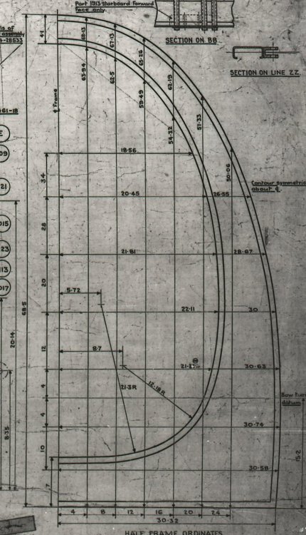
-
Frazer Nash FN5 gun-turrets
Fidd88 replied to Fidd88's topic in LSM 1/35 and Larger Work In Progress
I'm self-taught on Fusion 360, via few tutorials online and then experimentation. I fear I don't even know what "parametric" means without looking it up! I did classical draftsmanship at school 40 years ago, but nothing since. If I can help with anything, I will, but such talents I have with Fusion are a consequence of sheer stubbornness, not training! In other words, there may others better placed to help. I used to the same scaled canvases in x y and z planes to work out the shape of the fuselage, and interpolate the shape of temporary bulkheads on which the curved geodetic panels can be built. In order to generate the MDF shapes around which each member has to be curved (a largely theoretical exercise currently) the fuselage shape with be sliced laterally along the lines of the 4 tubular longerons, and then those portions sliced again at 45 degrees to the vertical.
-
Frazer Nash FN5 gun-turrets
Fidd88 replied to Fidd88's topic in LSM 1/35 and Larger Work In Progress
...and here's a shot of our the line-drawings above were scaled and used as "canvases" within Fusion 360 to start relating the plan form of one with the side-elevation of the other, to start making 3d sense of the drawings. This was only the very start of the process and some 2.5 years were spent, most evenings, in refining the drawings little by little until the 3d model worked mechanically, and resembled as closely as possible, photographic references. There's upwards of 1300 distinct versions of the main assembly drawing, and around 3 times that for individual drawings of components. The reason for this is that with such a large multi-part assembly drawing, making new parts within the assembly drawing made my computer grunt with the strain, so sometimes I'd export a cluster of parts alone, make the new part in that drawing to conform with the exported parts, before importing the new part alone back into the assembly drawing.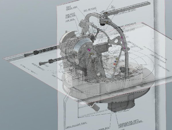
-
Frazer Nash FN5 gun-turrets
Fidd88 replied to Fidd88's topic in LSM 1/35 and Larger Work In Progress
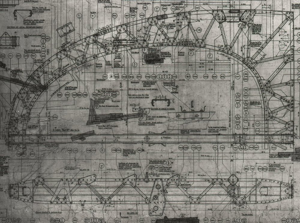
I've had a shufti at my now considerable collection of FN5 pictures, and found the two drawings from which derived (eventually!) the CAD drawings used to build the model. A number of changes had to be made to aid construction, but dimensionally they were initially correct to these drawings until experimentation proved that there are errors in these drawings if it's mechanically built as per the drawing. Hence a lot of faffing about making corrections until all the moving parts acted as they should, and didn't hit anything around them, or the inside of the cupola. These images are 600 pixels high, if you need higher res I can supply to an email address.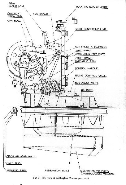
-
Frazer Nash FN5 gun-turrets
Fidd88 replied to Fidd88's topic in LSM 1/35 and Larger Work In Progress
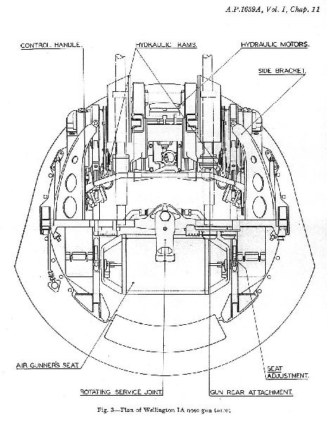
I can practically gaurentee you that no original drawings exist of the FN5 or FN5a. There are number of turrets reverse-engineered in CAD, much as I did mine, but they're all proprietry, eg Peter Jackson (of hobbit fame) has an aircraft modelling company that had drawn the FN20 in CAD. Despite my offering to sacrifice my first-born, they were sadly unwilling to let me have their CAD drawings of it! The Imperial War Museum may have replica RAF posters which shew annotated cut-away drawings of various wartime RAF turrets, but they're always non-isometric, so not easy to dimension from. It's just possible that the Yanks held onto the drawings they were given in 1940along with specimen turrets, to kick-start the US turret programmes. Amusingly the Americans took one look at our turrets, declared they could do better, (not unreasonable) and then quite independently made all the same errors we had in developing them ourselves before coming up with the very clever and reliable electric barbettes on the B29, Sperry Ball turret and so forth. If you search youtube for Fidd88 or go here, you find all the little films I made as they went together - triumphs and diasters! Fidd's FN5 model build films -
Frazer Nash FN5 gun-turrets
Fidd88 replied to Fidd88's topic in LSM 1/35 and Larger Work In Progress
Many thanks, to answer your question: Simple: There aren't any. No technical drawings of Frazer-Nash turrets survived to this day, so I got there by brute repetition of drawing the shapes, fitting them together in an assembly drawing, and continuously revising the designs over the best part of 4 years correcting things by reference to photographs and examination of the turrets at Brooklands. I had some help from Cosford and the BBMF who kindly photographed their turrets from angles not usually photographed, eg from underneath to figure out the hydraulic lines routing. The only two drawings I had to work from were book illustration line-drawings from the LH side and top, which proved quite incorrect, particularly on the geometry involved in keeping the sight-bar parallel to the guns whilst missing all the gubbins within the turret as the bar and sight moved, and much else besides. I did have help from Mark Evans who has drawn some components from recovered wreckage, and these CAD drawings, reworked to some degree, helped enormously in getting everything to scale. I'm currently working on the master-assembly drawing to incorporate all the dimensional corrections that were too impractical or expensive to fix on the current models. Once this drawing is complete, the intention is to rework the two turret drawings to the most common RC scale for aircraft carrying FN5's, and reducing the weight still further, and simplifying some aspects of the build. It can then be made available as a kit, or I may build turrets on a commission basis if there's demand. -
Many thanks indeed for posting those pictures, from me as well, as they've brought to light an error in my turrets too, so although it's too late to fix now on the built models, it'll be corrected on the master-drawings on which future builds will be based.
-
1/18 P51C Mustang "Lopes Hope 3rd"
Fidd88 replied to airscale's topic in LSM 1/35 and Larger Work In Progress
Cheers, what I know about US aircraft would fit on the back of a cigarette-packet. I wonder why they changed it (presumably during the war?) from the standard factory finish. I wonder if it was to facilitate larger nose-art? Or was a squadron-wide peculiarity? Or merely that theatre/period in the war? Incidentally, looking back over this topic, I thought it might be fun to each identify the specific aspect of this model that is your favourite. It need not be the most technically advanced, or even difficult-to-make. For me, it's the heat/oil discolouration of the metal plate around the exhaust-ports, which not only exactly resembles the effect on full-size aircraft, but makes the model "come alive" as if it'd been flying. -
1/18 P51C Mustang "Lopes Hope 3rd"
Fidd88 replied to airscale's topic in LSM 1/35 and Larger Work In Progress
I find myself running out of new superlatives to apply, it's just beautiful, and sets a standard, the sun if you will, for we "Icari" to aim for... A question if I may, the lower longitudinal line of olive-drab on the nose looks odd to me. I'm certain it was like that on the real aircraft, but is it not more usually a more horizontal line? IE wider laterally at the nose end? I've never seen one tapered thus, but then I'm not really knowledgeable on P51's...