Fidd88
-
Posts
196 -
Joined
-
Last visited
Content Type
Profiles
Forums
Events
Gallery
Everything posted by Fidd88
-

1:3.7 scale Frazer Nash FN5 turrets
Fidd88 replied to Fidd88's topic in LSM 1/32 and Larger Aircraft Ready for Inspection
One of the things I'm currently dealing with is the changes to scale that occurred during development of the turrets. I realised, early on, that at 1:4.5 scale, with the intended radial engines fitted, that there would be no gap between the cylinder-heads and the cowl. So the scale was changed to 1:3.7, and the CAD drawings changed to reflect this. Now that the turrets are complete I'm coming across all the consequential issues resultant from that change. First off, the Wellington will be just barely able to fit in my workshop with the wings removed, and then only with the turrets and supporting structure forward of the terminal rings at station 1A at the front, and 97 at the back, removed. The second thing I twigged is the jig I built (yellow thing) and the datum bar (black) were now 30cm too short! So I need to let-in a 30cm length to the existing datum bar, ensuring it is perfectly oriented in relation to the end of the cut bar, and, similarly lengthen the 4 measurement bars, and then strip and repaint all the markings on the datum bar which of course are now wrong! Bugger! Pics to follow of the current jig when re-worked. I'll also try and take care of the sag in the measurement bars else I'll need a correction table based on length and rotation.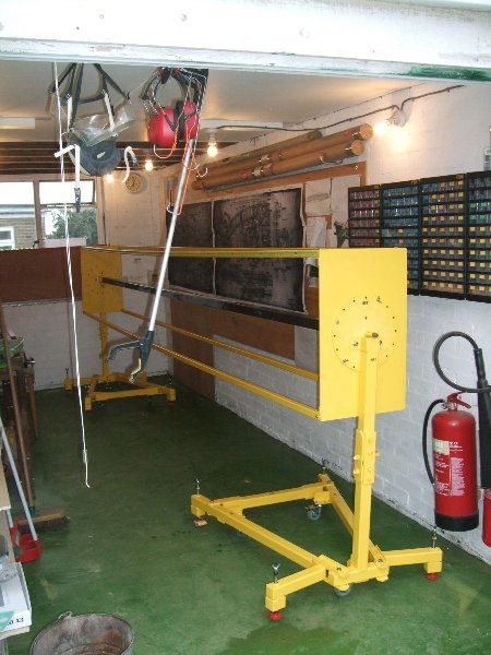
-
1:3.7 scale Frazer Nash FN5 turrets
Fidd88 replied to Fidd88's topic in LSM 1/32 and Larger Aircraft Ready for Inspection
Hehe. It looks worse than it is. I'm bloody hopeless with woodwork, so a balsa aircraft was never on the cards, but a very large model in metal is "doable". It's really the geodetic engineering that's my primary interest, so I've been thinking hard about this for around 7 years already. Although the Wellington's geodetics look very complicated to make, it's actually pretty simple. There are just two main types of joint on the whole aircraft, and once those are mastered, the only remaining obstacle is to define the required curvatures, and devise a method for making accurately curved members. Once those are solved, it'll go together as fast as I can bend them and rivet them into place. By the same token, once patterns are made for producing the curvatures, repairing crash-damage should be equally swift, just as it was on the original aircraft, assuming it's a hard-landing rather than an obliterating "lawn-dart" sort of a prang! Once the issues above are solved, I'd estimate being able to produce around 3 feet of fuselage a day, and about the same span-wise for the wing. So it's all the preparation that takes forever, once actual building commences it should be pretty quick, not least because it's fundamentally going to be very repetitive. -
1:3.7 scale Frazer Nash FN5 turrets
Fidd88 replied to Fidd88's topic in LSM 1/32 and Larger Aircraft Ready for Inspection
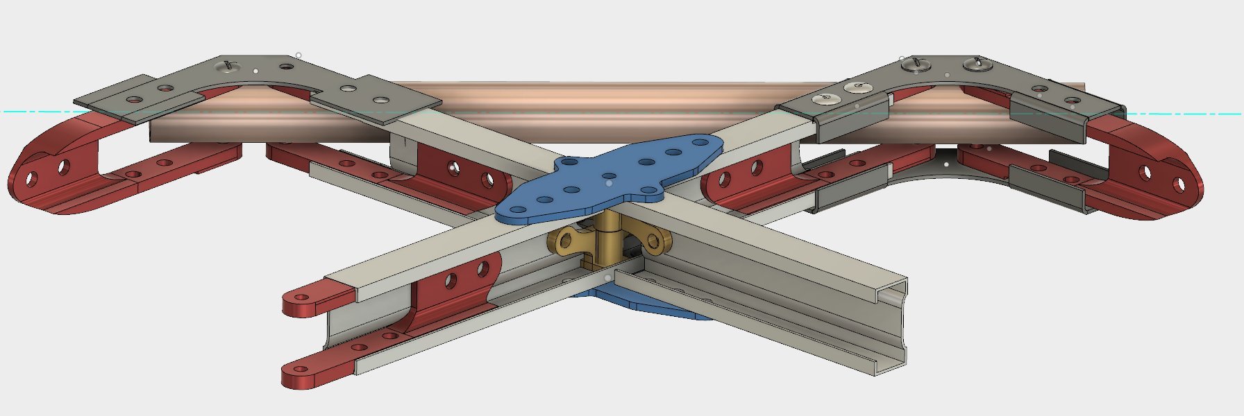
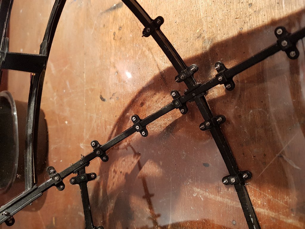
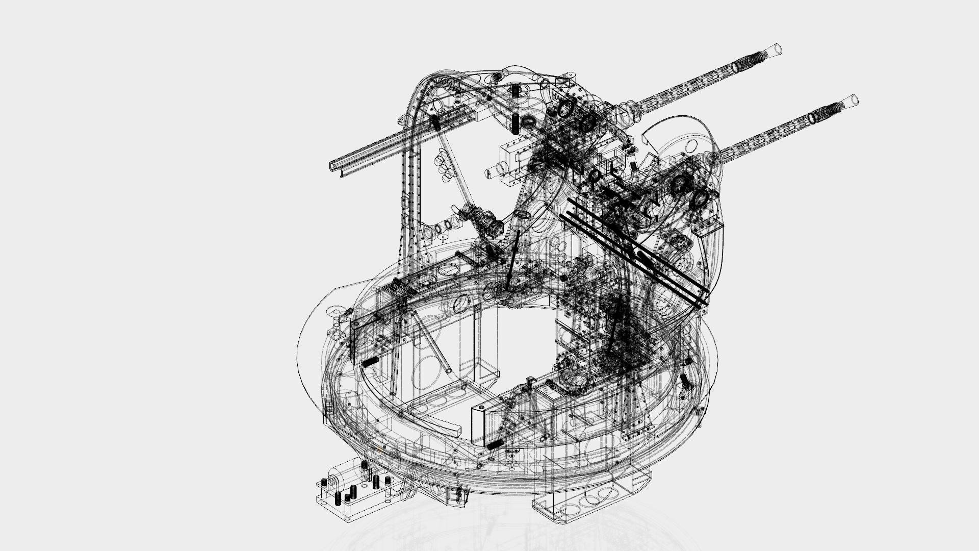
Thanks lads. Given the standards of modelling in here, that means a lot - especially after the best part of 5 years holed-up in the workshop or long hours at a PC doing the CAD work. It's funny to be finally free of them, if you understand what I mean. The next phase promises to be a but tricky. The geodetics will be made from extruded alloy, rivetted and bolted together once curved and notched to the required shapes. There's a lot of show-stoppers inherent in this, which if I can't solve, means I may have to do away with the geodetics in alloy. Similarly, there's some expense involved in sourcing the miniature rivet gun/compressor and Avdel rivets, and even more in the alloy extrusion die. So I need to sequence all this very carefully so I don't get caught with tools I can't use, or extrusions which are wrongly sized for being able to get the rivet-gun into (from both sides), both the preceding okay, but unable to get the internal sheer and gusset fitting made at a sensible price. Finally there's the issue of getting the "chains" made, which will sit inside the geodetic channel whilst it's bent, whose function is to prevent the cross-section of the channel from collapsing. All these things need to come together for the build method to work. I attach a picture of the two types of geodetic joint, one to cross-members, and one to the tubular longerons.. These now need to be redrawn, owing to the change from 1:4.5 scale to 1:3.7 scale. The picture below is not a 100% accurate to the real thing, although the function of all the parts are. This arose due to the fact that rivets in particular could not be reduced in scale to the required amount, which meant hole-centres are necessarily further apart in mine.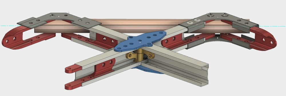
-
1:3.7 scale Frazer Nash FN5 turrets
Fidd88 replied to Fidd88's topic in LSM 1/32 and Larger Aircraft Ready for Inspection
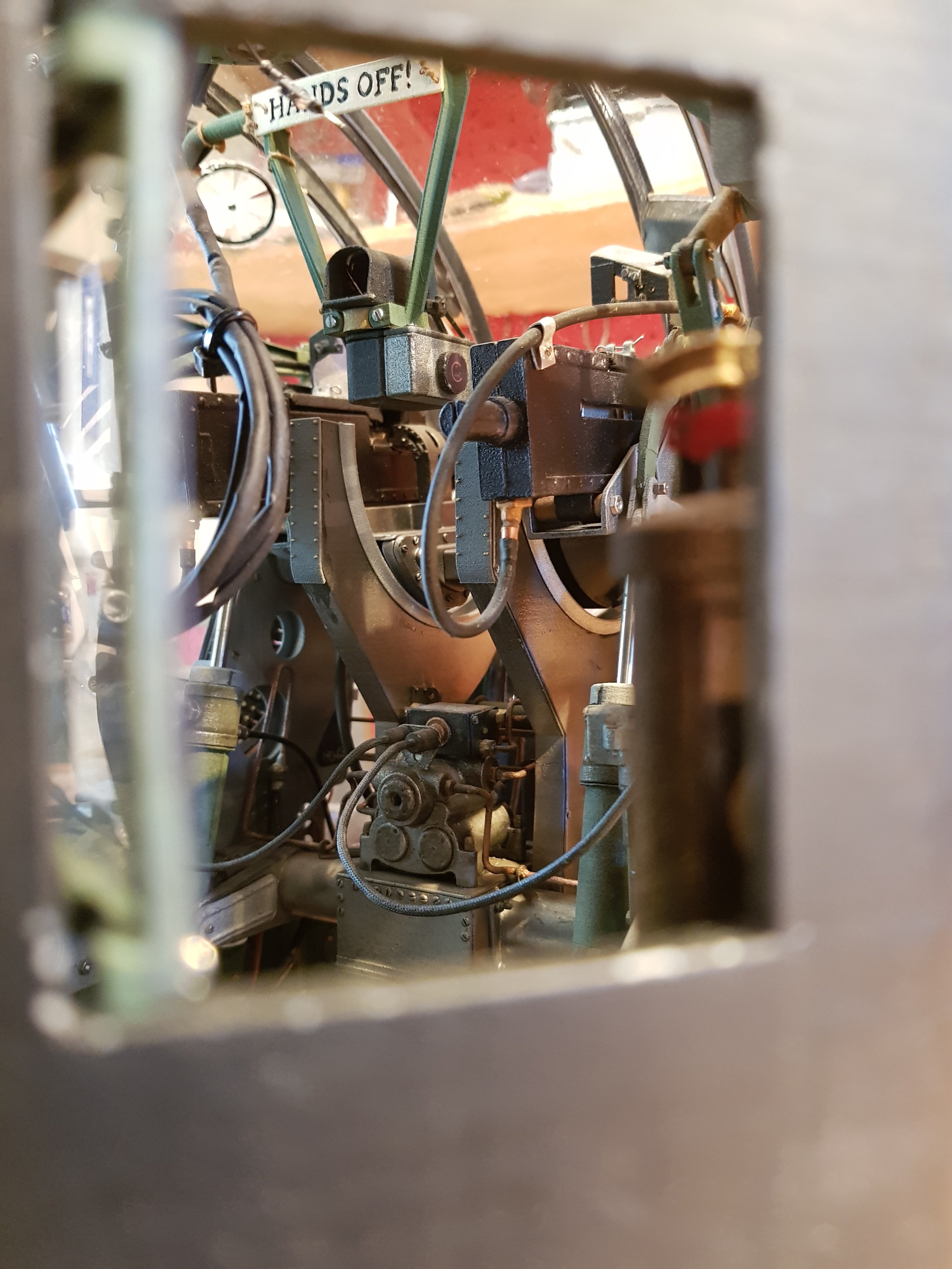
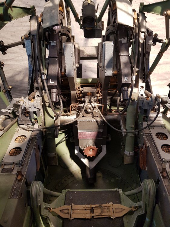
Cheers Gusmac. To be honest it's less complex than it looks, the elevation mechanism is surprisingly simple. Probably the hardest part was ensuring moving parts didn't collide with each other, and in particular, didn't collide with the underside of the cupola, whilst allowing the guns the full 105 degrees freedom of movement. Working at this scale meant being able to screw things together with tiny M1 screws and nuts, which allowed the build to be backtracked without causing damage, but also greatly added to the apparent detail. Sometimes there's "trickery" afoot, for example the control-handles are 3d printed as one solid unit, including the mounting of the handle. But I drilled, tapped and added screws nonetheless, as per the full-size turret which makes the control-handles appear as multiple small pieces screwed together, rather than one piece augmented by functionless screws...
-
Frazer Nash FN5 gun-turrets
Fidd88 replied to Fidd88's topic in LSM 1/35 and Larger Work In Progress
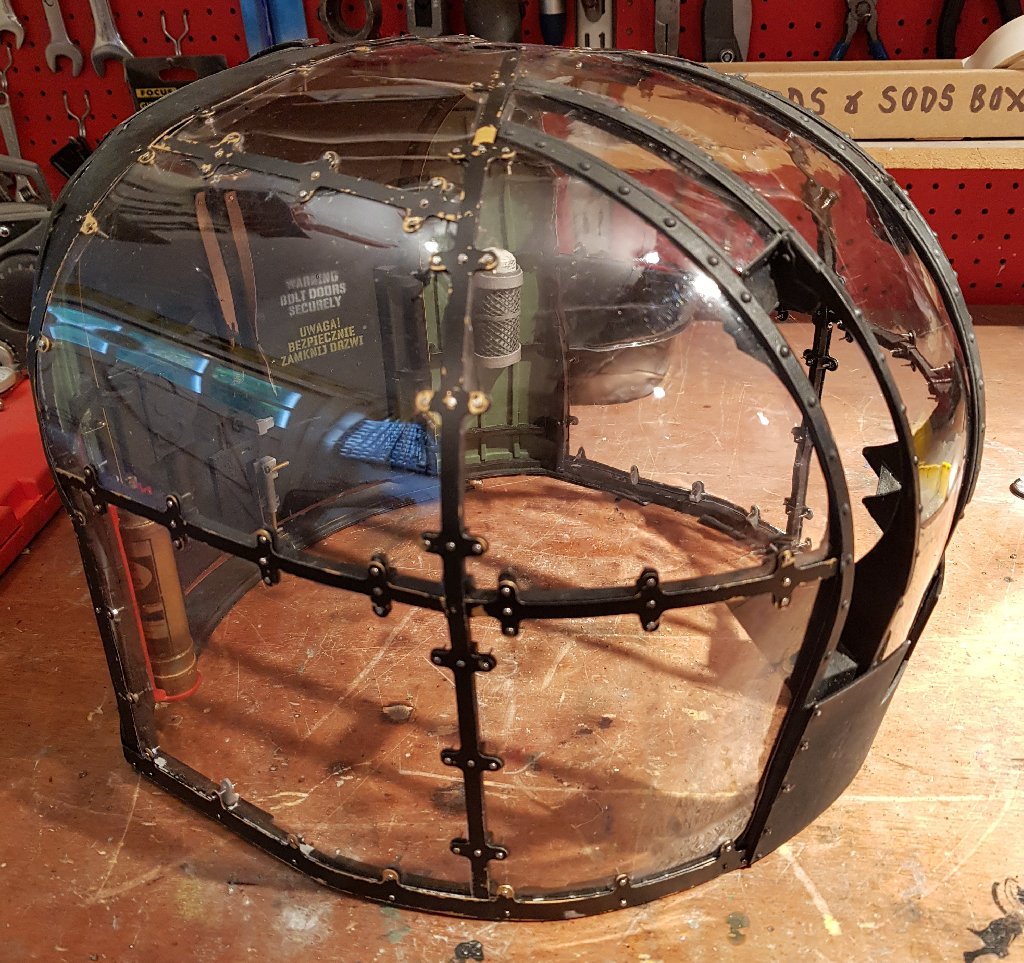
Thanks all, for the support and encouragement. As I've now completed the turrets, I've put a link to my final film on them in the "completed" section, but to save those following here from having to trawl over there, here's the link. All new footage and stills, and some narration. Final film of the turrets [Edit] And a few pictures..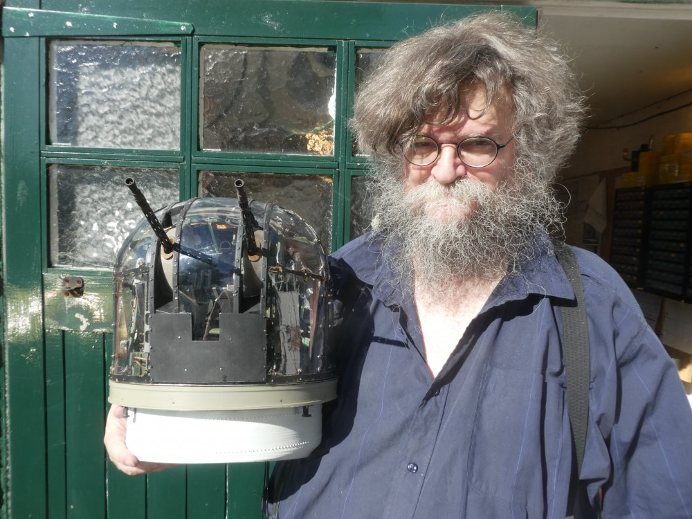

-
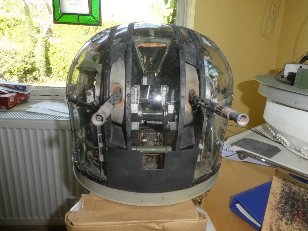
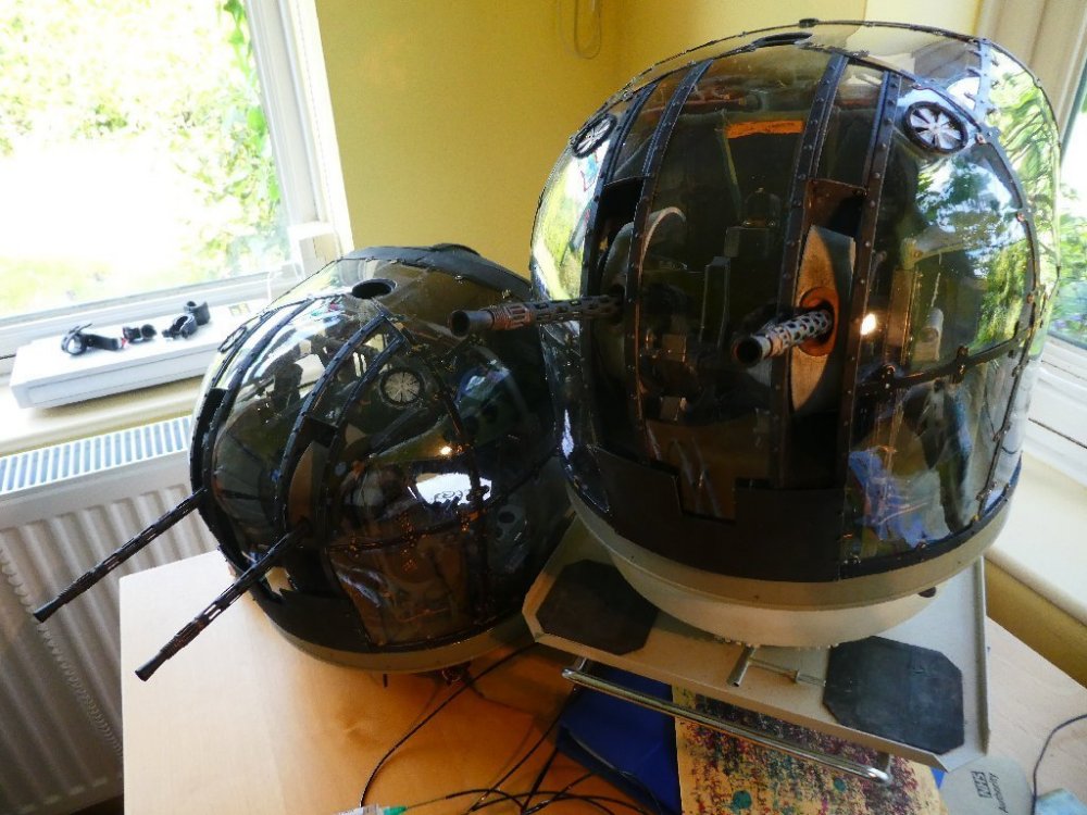
After nearly 5 years, I've just completed the pair of FN5 turrets for an RC model. The turrets are designed to be filmed from within, when the eventual model is in flight. So whilst the model isn't complete, a major portion of the effort is, in the form of the turrets. I attach a single picture, in case it might interest you, and a film and still taken from within the turrets. Cheers, 15 minute youtube film with narration
-
Frazer Nash FN5 gun-turrets
Fidd88 replied to Fidd88's topic in LSM 1/35 and Larger Work In Progress
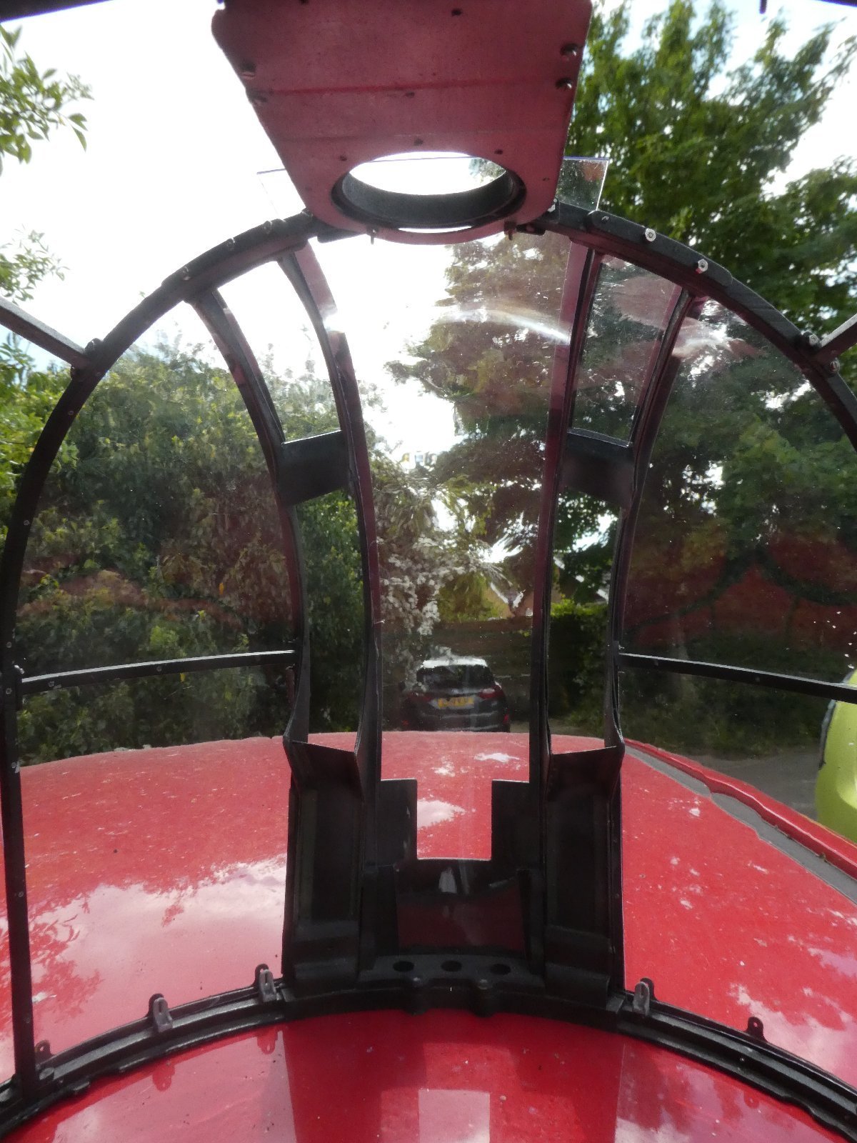
Ever had one of those days? One where everything just goes completely pear-shaped? As of first thing this morning, I'd retrofitted both cupolas with the 3d printed scale "penny-washers" and only had the pair of small windows above the slots to glue into position. This all went beautifully, until I noticed a deeply unwelcome drop of superglue had somehow arrived in the middle of the front half-left window, the one with the cut-out for the ventilator. "Bugger"! - quoth I (with feeling) I then mopped it off, and tried polishing it out with some acylic polish. This extended the damage by spreading the interior of the turret with blue spots of polish and did nothing to the blob of glue. "Bugger!.. with bells on"! At which sanity prevailed - not before time - and I walked away from all the tools and workshop lest any further cures of mine did yet more damage. An hour later, after a consoling mug of tea, I returned, and decided to replace the quarter-panel, refitted the ventilator to it and cleaned-up the mess "the erks" had left, arriving back at the position I commenced at 8am this morning. Sad, but wiser. Any further window-panel fixing will be done with my tried and trusted tiny-machine-screws, and if ever you see me reaching for bloody superglue, kindly whisper "remember the cupolas" to me, and I will cast it into outer-darkness with extreme prejudice. Other than that, the last few days have gone well, with the front-turret tub painted and fitted, and the both cupolas complete (notwithstanding today's vandalism) So, a couple of wiring faults to chase down, and then they'll be salted away for eventual fitting. One long-put-off bit of mathematics also occurred, with me working out the scale of the eventual model, after lots of close measurement. I worked it out from the size of the turrets: 1:3.703, and via the ratio of the turrets to the length of a large scale plan from front to rear terminal rings, and thence to the known length of a full-size Wellington. Result 1:3.706! So that's comforting. The scale was 1:4.5 when I started the initial drawings for the turrets, but I changed the scale as I was concerned that at 1:4.5 there was virtually no clearance between the diameter of the chosen engine, and the cowl. At 1:3.7 I've a bit more wriggle room. I hope your projects are proceeding well, and that none of you are using superglue! -
Frazer Nash FN5 gun-turrets
Fidd88 replied to Fidd88's topic in LSM 1/35 and Larger Work In Progress
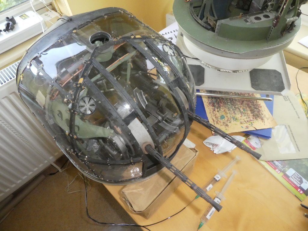
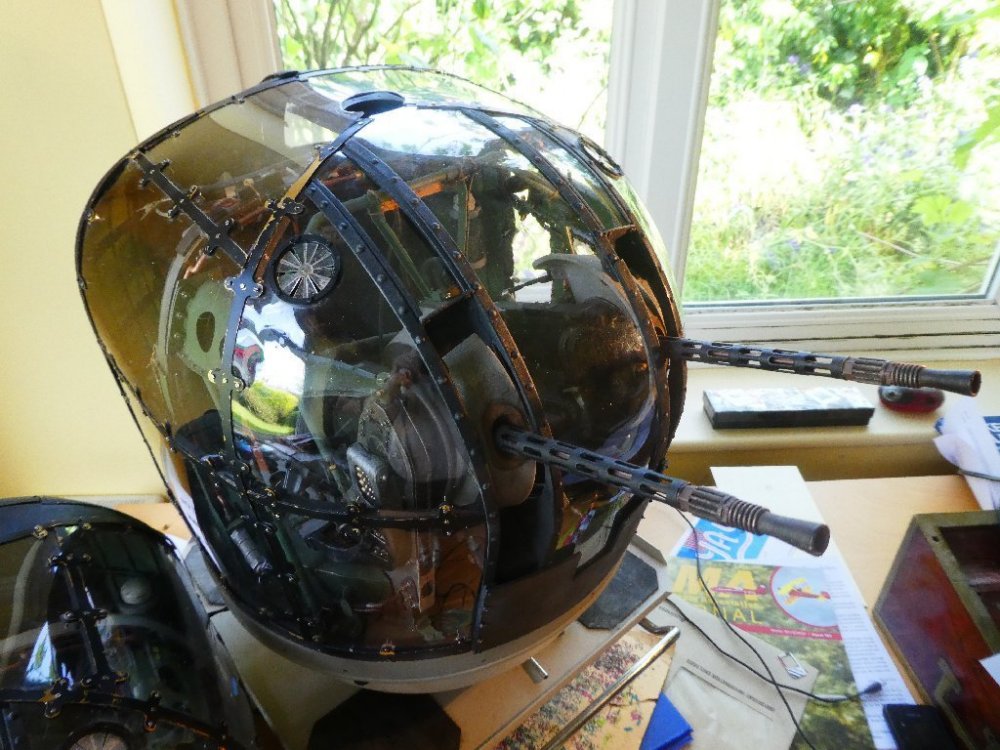
Bit of a red-letter day. Over the last day or two I've assembled the cupola for the rear-turret and married these to the internal mechanism. I decided to rework the clips which hold the perpex panels in place with the addition of 3d printed scale "penny washers", painted to a brass colour. These make putting the nuts on easier, as the screws can't fall out when trying to start the nut on the thread, and look much better from the inside. So when they've arrived and been painted, I need to refit most of the clips, this'll be much easier to do second time around with each window panel being registered by all but one machine screw - at a time. Also still to come is the "tub" for the front turret, qv. I'm probably also going to make stands for them, similar to those used at the central-gunnery school, where gunner's under training could operate turrets powered hydraulically by a nearby lorry-borne generator. It'll be ages before I'm in a position to mount them in the fuselage. At some point I'll open the doors and try and photograph them from the view I hope to eventually obtain from the "gunner's eye" FPV cameras.
-
Frazer Nash FN5 gun-turrets
Fidd88 replied to Fidd88's topic in LSM 1/35 and Larger Work In Progress
Cheers Phil. The hard work was really the CAD side of things. Not that I'd really want to do it all again but when it finally prangs - as all RC aircraft eventually do - I hope to have lots of film footage to remember it by! Having built the turrets, I now reckon I could rebuild them inside 6 months - as opposed to the best part of 5 years to go from initial drawings to where we are now.. Further to this, I've just posted a new film: https://www.youtube.com/watch?v=ppVC-NaSqBM -
Frazer Nash FN5 gun-turrets
Fidd88 replied to Fidd88's topic in LSM 1/35 and Larger Work In Progress
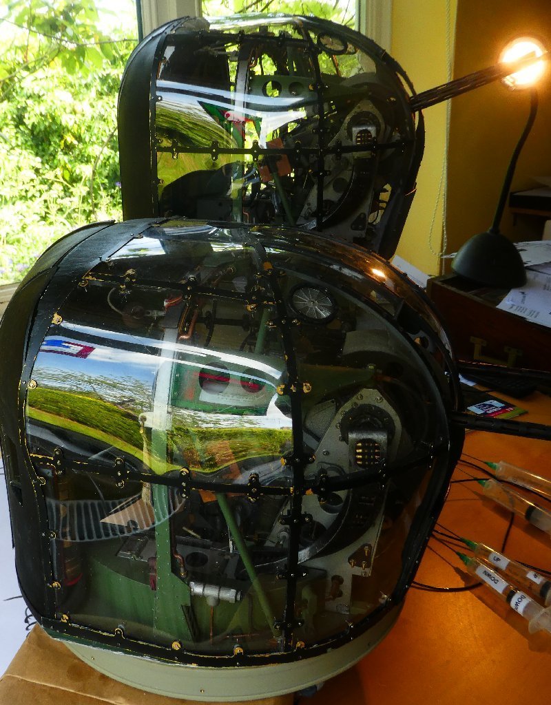
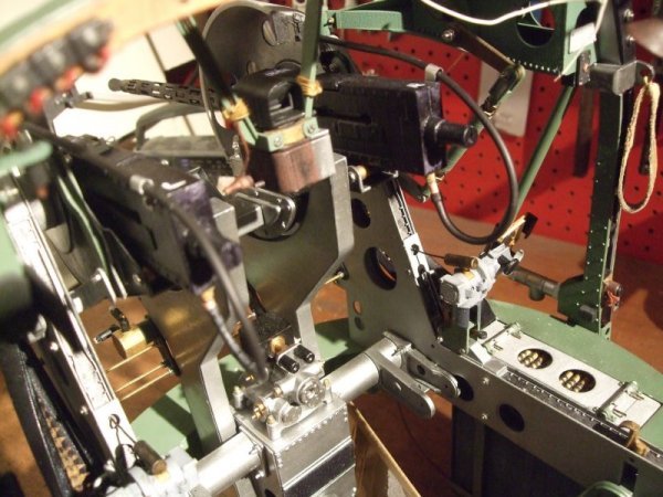
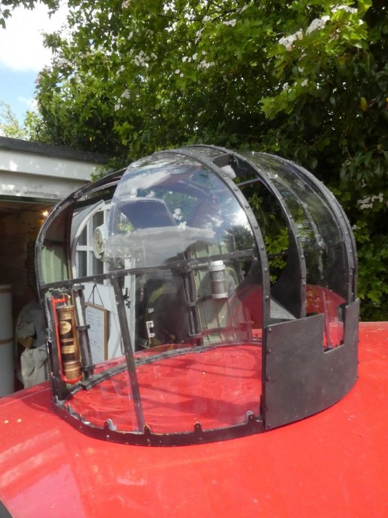
Well, to remains to be seen if it can. as there's plenty of potential "show-stoppers". The intention all along has to be produce a large model Wellington 1c, in Polish/RAF service, with interior cameras - some FPV - to take footage from within the model in flight - hence use of proper geodetics internally. The second aim, is to build the model using alloy geodetics, as close as possible to those used on the original machine. Possible problems are radio-interference from the metal "basket" structure (it's basically a Faraday cage!) to expense and difficulty in construction, to metal-fatigue. Even if I can build it, it's hard to see the chance of multiple successful flights being higher than around 30%, and that may well be optimistic. On the other hand, it'll be deeply satisfying if it comes off. Some builders have made geodetics in wood, however these are usually limited to the upper-surface of wings and tail-plane, where it shews, but otherwise use bulkheads and stringers and longerons in balsa, ie not geodetics, for the fuselage. If mine works, it'll be the first metal Wellington, and the first all geodetic model throughout.. Today has been spent on the rear-turret cupola having finished the front turret cupola yesterday. I reckon another 3 days should see the rear turret cupola finished. I had some good news yesterday, the chap printing the front turret tub has despatched it, so once that arrives I'll be able to bring both turrets to completed status, and salt them away whilst moving on to the metalworking side of the project. Attached are some pictures of the front turret cupola on the turret mechanism. Since these were taken I've added the rings on the ventilators. if you're new to this thread, you may wish to check out my youtube channel which documents the build, and all the trials and tribulations of developing these prototypes - the intention being, eventually, to produce these as a "kit", if I can get the unit cost down. As currently designed, they're terribly time consuming to build, and very expensive.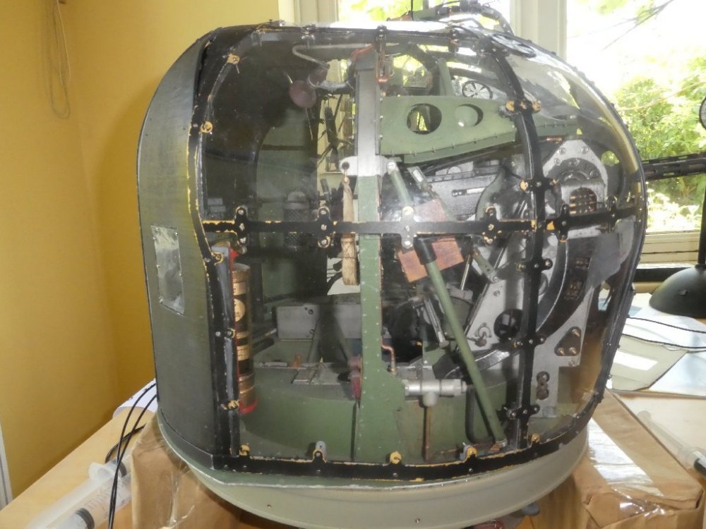


-
Frazer Nash FN5 gun-turrets
Fidd88 replied to Fidd88's topic in LSM 1/35 and Larger Work In Progress
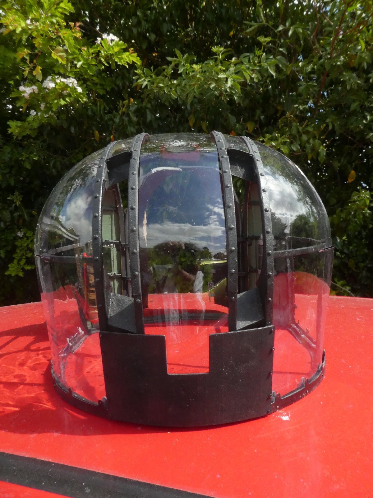
Cheers! It also makes a rather fine hat! -
Frazer Nash FN5 gun-turrets
Fidd88 replied to Fidd88's topic in LSM 1/35 and Larger Work In Progress
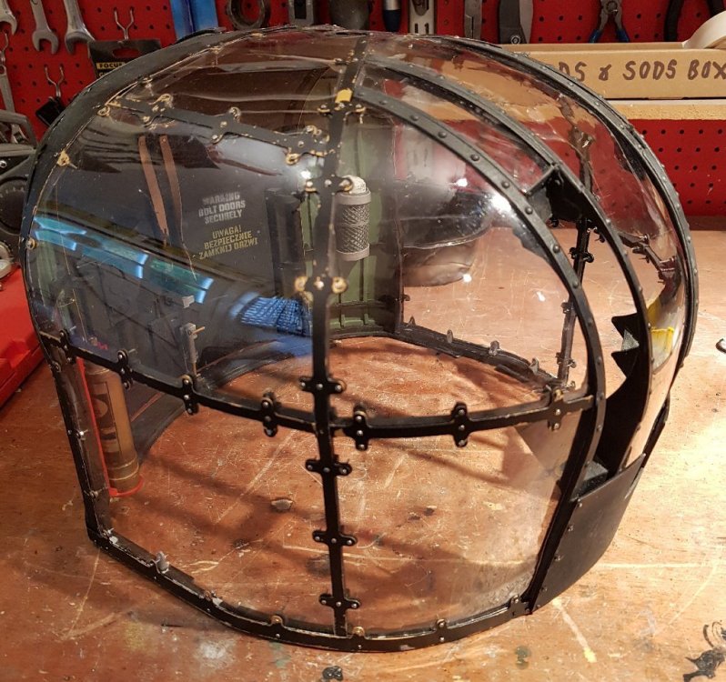
After a marathon effort today, the front turret cupola is finished, bar for the ventilators in the quarter right and left window panels, the position of which I need to research. In the cup2.jpg note the 3 M1 machine screws and nuts per attachment. Each nut was started with my cocktail-stick with a blob of blutak, and has to be placed on the thread end, then very gently teased with the stick until the nut starts on the thread, whereafter I can go on in with nut-spinner and jeweller's screw-driver to finish it. Once the cupola is complete, I'll put a little locktite on the exposed threads to prevent the nuts unwinding with vibration. Once the cupolas are completed I'll post some pictures with them on the turrets. The front of each cupola engages with "feet" on the turret assembly, and then is held down at the back by two screws which go down through the cupola and through the alloy plate on which most of the turret mechanism is built.

-
Frazer Nash FN5 gun-turrets
Fidd88 replied to Fidd88's topic in LSM 1/35 and Larger Work In Progress
The vac-forming for the forward windows of the turrets has now been done, and some properly sized poly-carbonate 1mm sheet sourced for the side and overhead windows which are simple-curvatures. vac-forming film Edit - Addendum: Pictures of front and front quarter panels, with as yet unpolished view through Perspex panels in 3rd shot. Very hard work on the fingers! By Sunday evening, gremlins permitting, I should have completed the front turret cupola completely, which will involve refitting all the brass strapping on the exterior of the turret, and then bolting these through the Perspex onto the fittings on the other side. Very tedious, but so far going fairly well.

-
Frazer Nash FN5 gun-turrets
Fidd88 replied to Fidd88's topic in LSM 1/35 and Larger Work In Progress
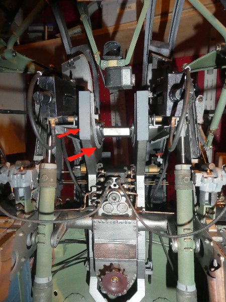
I've been more or less stalled on this project, for want of materials and restrictions on movement due cv19, meaning that I can't get the vac-forming done. I did get a small tranche of final parts yesterday which have since been painted and fitted. These consisted of a pair of flanges to widen the apertures of each of the spent-cases chutes, and a reinforcing plate on the face of the chute as viewed by the gunner. In both cases these were to widen the apparent width of these chutes which although width'd from the best drawings I could find at the time, are rather too narrow. Also in this last load of parts were fittings which will be glued and screwed to the cupola structure, through which the Perspex window panels will be bolted. I've yet to fit these. Pics attached, the red arrows point to the new reinforcement plate with simulated rivets, and the two flanges per chute. New Films covering this, and various other elements of the build in the usual place. I hope you're all keeping well and out of the path of this bloody virus.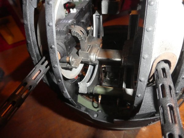
-
That's coming on really nicely! You could, if you were feeling really keen, have a go at adding the various hydraulic pipes which are visible especially on the outsides of the arch and thence forwards around the forward face of the chordal braces. Very fine single-strand copper wire could do the job nicely. I don't know if Manchester turrets had them, but Wellington turrets of this era had rotatable ventilators in the top corner of the half left and half right (as viewed by the gunner) front window panels. These were to clear cordite-fumes, which otherwise could make the gunner feel pretty unwell in a confined space.
-
An absolutely fascinating build to follow, thanks for posting this. The planking is particularly clever.
- 185 replies
-
- 2
-

-
- Scratchbuild
- 1/32nd scale
- (and 1 more)
-
1/32 Revell Bristol Beaufighter build
Fidd88 replied to CrankyCrafstman's topic in LSM 1/35 and Larger Work In Progress
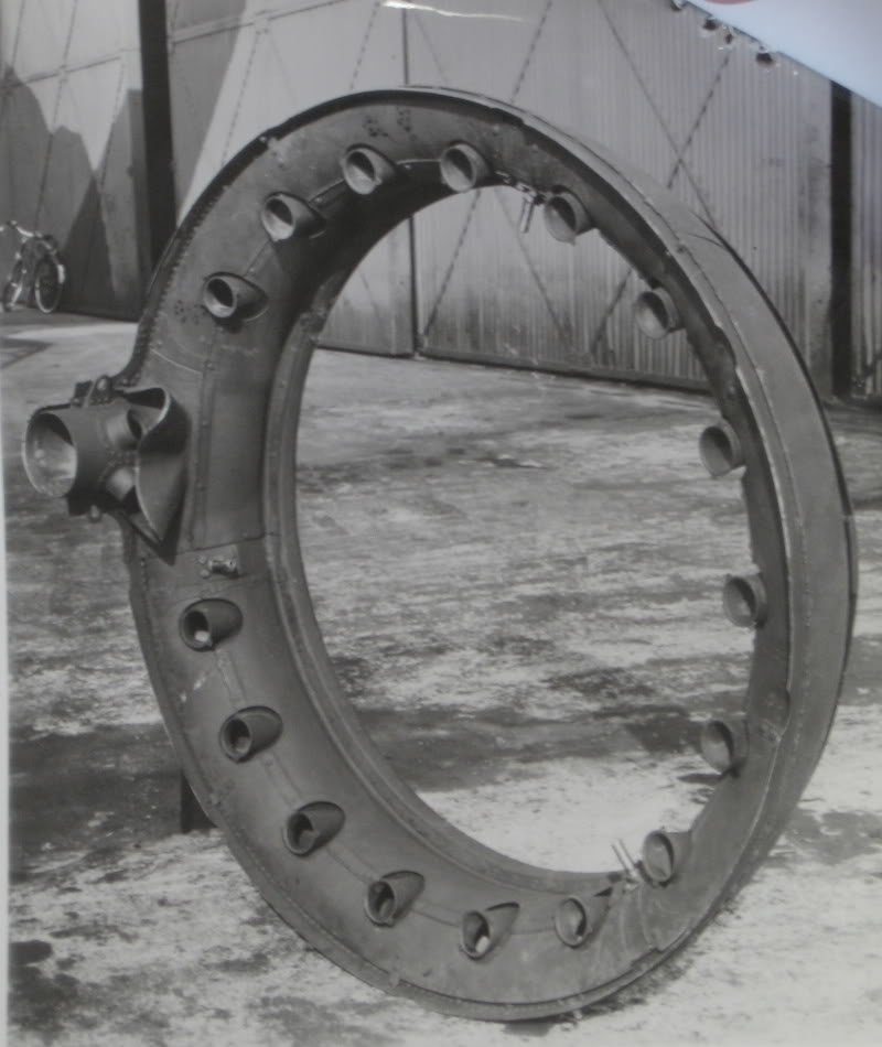
We seem to be talking cross-purposes. A Pegasus is a single-banked 9 cylinder radial, a Hercules is a 14 cylinder double-banked. In the shot above, there are two exhaust ports per cylinder, so if a Pegasus, we'd expect 18 feeds into the Townend ring, an if a Hercules, only 14 (I think!) because they join the ports of the rear bank with those exiting the front bank of cylinders, before they enter the Townend ring. Do you agree? -
1/32 Revell Bristol Beaufighter build
Fidd88 replied to CrankyCrafstman's topic in LSM 1/35 and Larger Work In Progress
Correct. I think it's from a Wellington, probably a MkIII, as it's configured for the "Hercules" 14 cylinder sleeve-valved and double-banked, rather than the 9 cylinder "Pegasus". I'd be interested to know if the Pegasus also branches exhausts in the same way two into one. -
1/32 Revell Bristol Beaufighter build
Fidd88 replied to CrankyCrafstman's topic in LSM 1/35 and Larger Work In Progress
The confusing thing is that each pipe into the townend ring is served by two cylinders, one a straight pipe, the other forking into it the adjacent cylinder. So I presume the cylinders have two exhaust ports per pot.
-
1/32 Revell Bristol Beaufighter build
Fidd88 replied to CrankyCrafstman's topic in LSM 1/35 and Larger Work In Progress
They're the chaps. Sorry I didn't mean to impugn your model-making, but you'd be amazed at how often it's wrong in the RC modelling world. -
1/32 Revell Bristol Beaufighter build
Fidd88 replied to CrankyCrafstman's topic in LSM 1/35 and Larger Work In Progress
I can't tell you how much I've enjoyed seeing this build. My own father died when I was 5 or so, and one of a handful of clear memories I have of him is building the 1/72 Airfix-kit of the torpedo armed "Beaufighter" ("Beaufort?") variant. I got confused about the instructions, and stuck it on the top wing hard by the nacelle, and was inconsolable, I imagine, at getting it wrong. I can remembers him working with me for hours to remove to the torpedo and remedy the damage with files and sandpaper... I did RTFM more carefully after that, but it's a fond memory all the same. I can also clearly remember the 1:72 Airfix "Lanc" which to me was HUGE, that I received one birthday or Christmas shortly thereafter. Probably chosen for the lack of torpedoes! Incidentally, the "collector ring" is called a "Townend ring", which is different to a normal exhaust collector ring, in that it has an additional aerodynamic shroud surrounding the collector ring, through which cold air is ram-fed. This serves to flame-damp at night, quietens the engine note and heats the faces of the cowl otherwise vulnerable to impact icing. It also provides some drag advantages, and assists cooling of the cylinders. It's a very clever bit of kit. On model instructions, it's often suggested to paint it bronze, but actually it should be an alloy colour with increasing heat discolouration towards bronze brass and blue shades as you move away from the leading and trailing edges of the ring towards the center line. At the lead and trailing edges of the Townend, the metal is rivetted, double thickness, and therefore tends not to heat discolour to the same degree. (Examined a real, HOT one, on the Royal Navies Swordfish when it dropped into the airfield I was flying from one afternoon.) -
Frazer Nash FN5 gun-turrets
Fidd88 replied to Fidd88's topic in LSM 1/35 and Larger Work In Progress
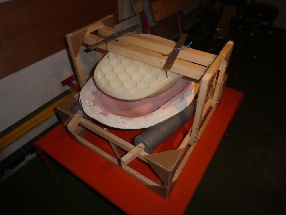
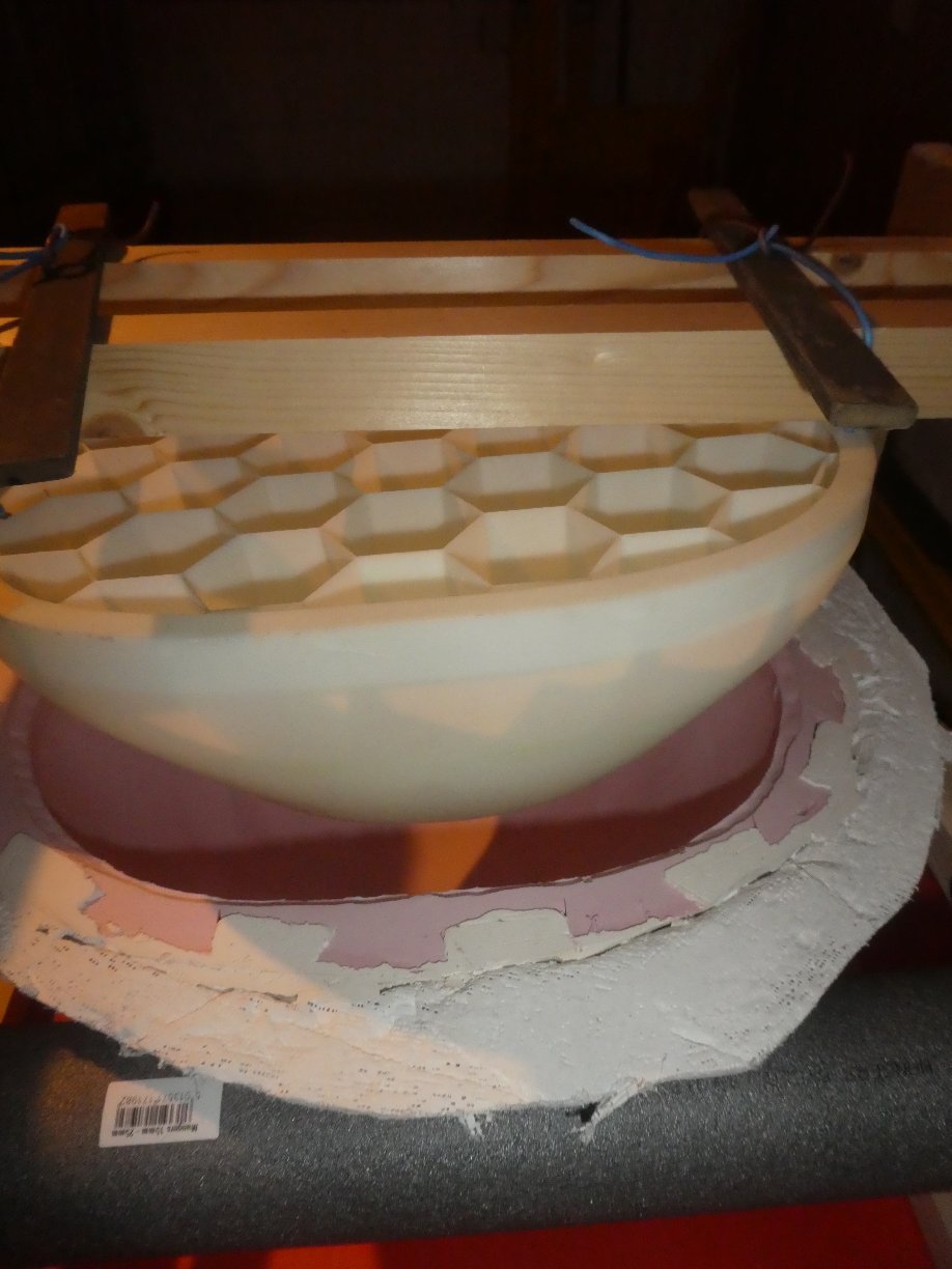
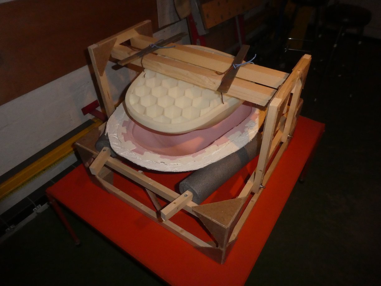
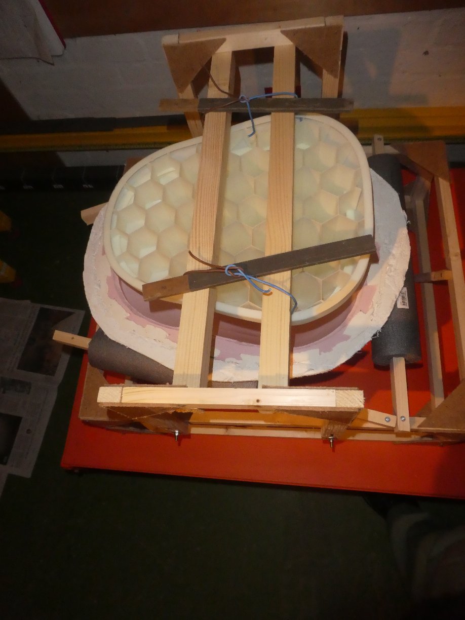
I've had a very difficult couple of days, demoulding the resin from the silicone and plaster mould, made all the more tricky by an error when applying the 2nd and 3rd coats of silicone. It took so long to demould, as I was very mindful that if I became impatient, it was going to be very easy indeed to damage the casting, as whilst the resin is very strong in compression, it's pretty weak in tension, and that any overly enthusiastic attempts to part one with t'other was going to result in a bust casting. Two days later, I'd got the bugger to separate cleanly. I learned lots throughout the whole process, and will be much better at it next time. The wooden box support worked really well in terms of minimising mess and keeping what would otherwise have been a very unwieldly mould under control. FILM of demoulded tool and AAR -
Frazer Nash FN5 gun-turrets
Fidd88 replied to Fidd88's topic in LSM 1/35 and Larger Work In Progress
Cheers, I'm pleased you're getting something from it. Yesterday, I did the resin pour, which for various reasons was harder than I expected. Altogether far too many bubbles I think, which may prove disasterous when the casting is under vacuum or during the heat-treat. I didn't know at the time, but I wasn't at my best. By later afternoon I had a high temperature, and slept over 20 hours straight. Hey ho. Latest film here: FILM -
Blimey! never seen one of these used before..
Fidd88 replied to Fidd88's topic in General Discussion
Cheers. I thought it quite remarkable in the hands of an expert. It's fairly redundant for me as I can 3d print parts much more accurately, but of you can't draw in CAD then this has some merit I think. -
Frazer Nash FN5 gun-turrets
Fidd88 replied to Fidd88's topic in LSM 1/35 and Larger Work In Progress
I took a few more pictures this evening having sorted the male-mould attachments. The little sticks on top are to tension the wires so that if can't move fore / aft or athwartships, they'll be tacked in-situ to hold them fast for the duration of the cure. I still need to cover the ABS male mould with mould-release spray before setting it up again for the pour. So you can now see how the whole edifice goes together. It's a bit "Heath Robinson", but should do the trick. There'll be an additional sandbag under the plaster-mould so that not all of the weight is being carried by the flanges of the mould. The current guestimate for the all-up weight when the resin is poured is 12kg, plus the weight of the mould which is about the same weight, so call it 25kg, or 50lbs if you will, and 12kg once demoulded.