Fidd88
-
Posts
196 -
Joined
-
Last visited
Content Type
Profiles
Forums
Events
Gallery
Everything posted by Fidd88
-

Frazer Nash FN5 gun-turrets
Fidd88 replied to Fidd88's topic in LSM 1/35 and Larger Work In Progress
It's nothing but compound curves! The formers are the shape of the path of the geodetic, not the fuselage as measured around say a bulkhead. But when installed, they will naturally create the shape of the fuselage. So one half of the formed shape covers the path as it goes upwards and backwards at 45 degrees from the longeron to which it is bolted, and then the other half describes the path from the midline backwards and downwards towards the longeron on the other side. The result should - If I've not bollocksed-up the theory, describe the shape of a geodetic passing from one side to the other, from forwards to aft as it describes the shape of the tapering fuselage. This is the reason for the "measuring bars" on the jig. The first thing built will be temporary bulkheads which constrain long alloy tubular longerons the length of the fuselage. At very precise points, these have holes drilled in them to take the fitting (red in the picture above) which attach the beginning or end of a geodetic channel to a longeron. The measuring bars carry a sled with a plumb-line, and have measuring tapes on them, so I can simply slide the sled to the required distance, mark the longeron, drill it, and temporarily fit one end of the geodetic. When a crossing geodetic is fitted, I can then mark both where the notches need to be cut, and eventually take them all off and notch them before fitting everything for good. That may change in practice, but that's the plan. The easiest way to figure this is to take an old football, draw some "latitude" (horizontal) lines in it, (these are the paths of the longerons), then lines that are great-circles (like the equator or any line of longitude) where the centre of the circle described is also the centre of the ball. The great-circle paths drawn are at 45 degrees to the latitude lines, and cross each other. Result - shape of football defined by both. Same principle, only a little more complicated, with the fuselage. -
Frazer Nash FN5 gun-turrets
Fidd88 replied to Fidd88's topic in LSM 1/35 and Larger Work In Progress
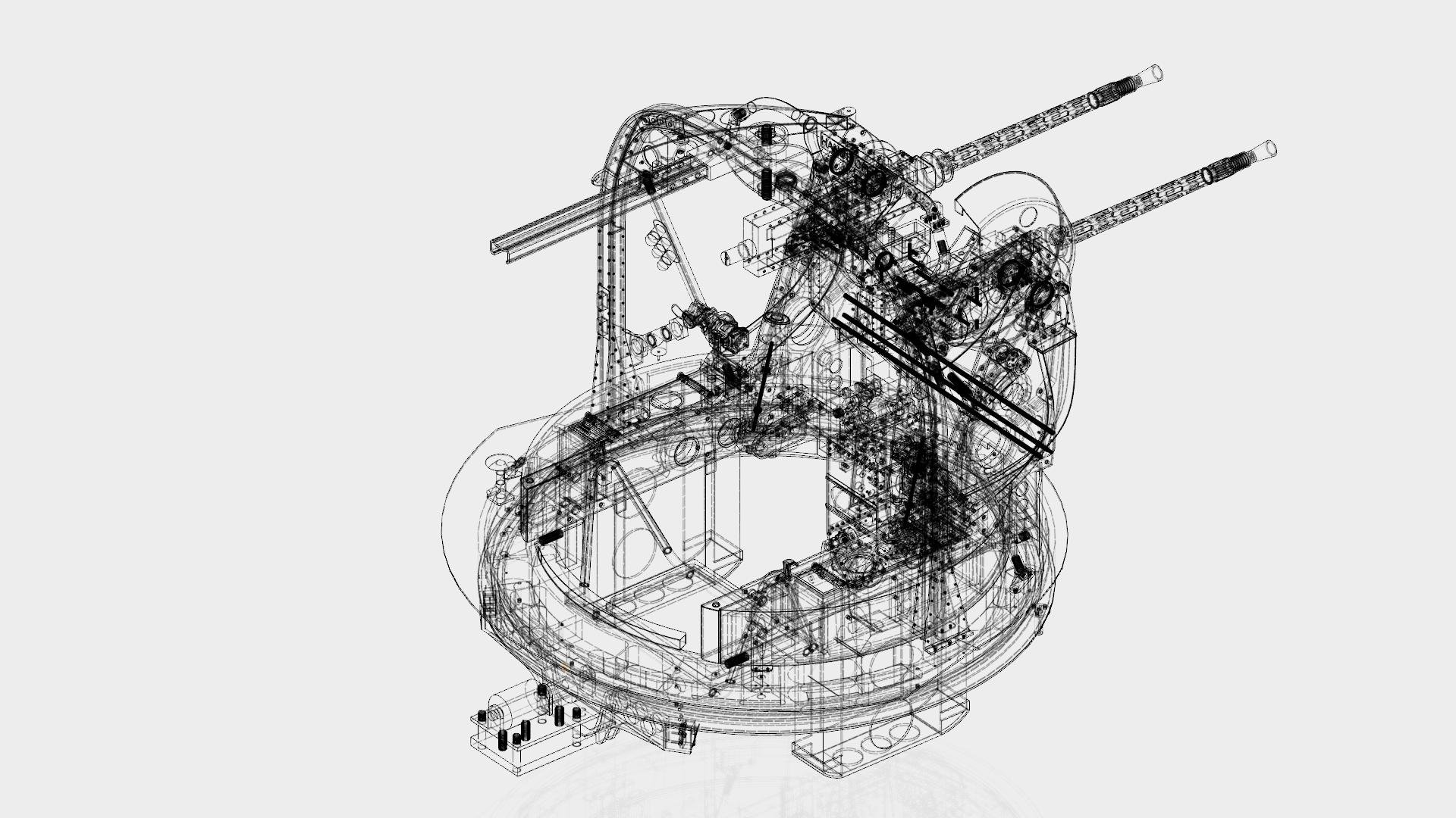
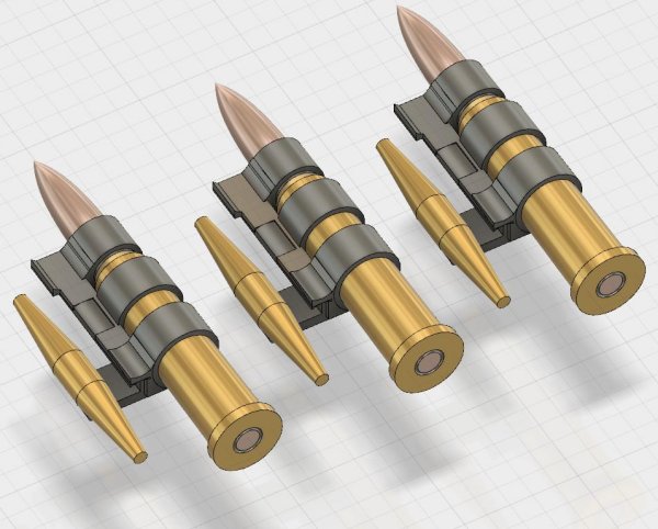
Such news at there is: I'm now at the phase of preparing to start metalwork, to fabricate the curved geodetic channels required to build the fuselage, wings and tail, and know how I'm going to go about it. The geodetic channel will be extruded in it's required cross-section, with a wall-thickness of 0.8mm (31 thou"). When it comes to bending it, a steel cable with a heavy weight on it will cause it to bend as the extruded tube is bent around a wooden former by being "wound" onto it, the steel cable causing it to conform thereto. Some 300 different formers being required just for the fuselage. These formers will be CNC cut, and arranged in pairs to create the required shapes when the path of the geodetic goes over the centre-line of the fuselage. One of the chief problems to solve, has been not allowing the cross-section of the geodetic to collapse as it is bent. When Brooklands Museum were making new geodetics for R for Robert, they encountered the same problem, and my solution is similar, except for the steel cable. What will happen is I will have CNC cut, hundreds of alloy plates, each being a fairly snug fit inside of the cross-section, threaded onto the steel cable, with softer thin plastic washers between each pair of alloy inserts. This (hopefully!) will allow each geodetic channel to be progressively curved onto the former without deformation of the cross-section. That's the plan anyway. The next issue was cutting the notches required in the channel, at each cross-over of geodetic members. This had me stumped for a long time, as the only thing I could think of was using a grinding-disc, and this ran a severe risk of creating tiny imperfections in the cut which would be a source of metal-fatigue. I eventually had the happy inspiration of using a cutting-disc on the angle-grinder, with a mount for the grinder and a "suitable system of gears and levers" to keep the depth of the notch, and the angles of the cuts precise and correct. This mount isn't designed yet, but it is buildable. The only remaining task is the horizontal cut at the top of the notch which has curved corners, lining up with the two angled cuts done with the cutting-disc. This will be done by hand with a purpose-made steel chisel, probably impelled hydraulically using an adapted bearing-press or jack. Provided the preceding works, and it should, that's all the shaping problems sorted. The next thing to address is access of tools. The rivets I intend using are Avdel Micro-rivets, but the pneumatic rivet-gun supplied has a rather large nose, making getting it in where I need it to go, is a problem. Tomorrow I'm off to see them, to see if a custom nose can be made, or is viable for me to have made, and then to ensure the cross-section of geodetic allows such an adapted tool into where it needs to get. Once all that's squared away, the remaining tasks are to ensure a CNC company can fabricate thousands of the small fittings required to make the standard geodetic node bolt and rivet together. I attach a rather old picture of the two types of joint prevalent on the airframe. Which hopefully will allow the preceding to make sense! So, nothing physically to shew for it, but lots of theoretical progress as to what's needed to go forwards. Should be an interesting year ahead!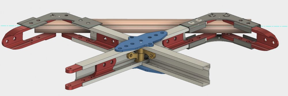
-
No problem. Even if you don't use it on this model, a knowledge of how the components look like, and how the different types of rams operate. It might spark an idea for a project? I found the link to the film I made as I was assembling the turret rams, which shews the different parts.
-
Honestly, pneumatics are a complete doddle. You've single-acting - one way - and double acting - two way. The first may likely of no use to you. Go to ocaire.com, find a suitable miniature (probably double-acting) ram, and buy some large syringes, and some pneumatic line (black 2mm PVC tube iirc), and start "playing". Connecting them up is simplicity itself, pvc put metal collet on tube, press tube into joint fitting, press collet back up tube and onto joint-fitting. Connect other end of tube to large syringe with non-sharp needle - (usually a pink plastic fitting with needle) and your done. It takes longer to type. Ring Ocaire, they're very helpful in explaining what you'll need, it's not expensive and really is straightforwards, The "hard" bit is going to be getting the geometry right, and adapting or 3d printing the articulated parts so that the whole mechanism "works". My turrets were the very first time I'd done any pneumatics, so don't sell yourself short, if I can figure it out.....
-
I'm glad to have been of help, Good luck with the bulldozer, I look forward to seeing it. How big is it? If the model is huge, you could look into pneumatic (air powered) rams for the bulldozer and digger-bucket on the back. Movement on a model is really striking if it's doable, and it's a lot of fun to do. Put on a diorama base, the pneumatic lines could be concealed in the base and just brought out to connect the syringes to start making things move,,,, Provided the model is big enough, the main rams for the dozer blade look emminently achievable. On my turrets I 3d printed a thin cover for the metal ram so that it appeared, as a far as possible, the same as the hydraulic one on the original turret.
-
That's quite a beast! One thing I forgot to mention, is a peculiarity of how SLA works. If you've a "blocky" part, more than about 6mm (1/4") in 2 or more dimensions, then when it's printed, the inside of the part is left unfused - a powder. When I printed such parts I left - or made - a drain-hole in the part so that the powder could largely be tapped out. This has implications if you want to bolt through the part, when drawn, you need to put the cylinder of fused material around the bolt-hole, so that the bolt has something to pull against. The reason for this is that the fused exterior remains porous, and if a solvent got to the powdered interior, then odd things might happen. So not all printed parts are the same in terms of their internal structure. SLA Nylon has the surface appearance of an 'extra strong-mint' when unpolished, and similar but smoother if polished in an abrasive powder,
-
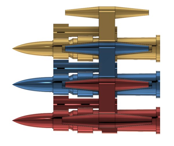
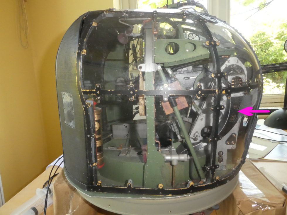
My worst moment arose out of a tiny change I made to the ammo chutes - and then "saved" - to put some tell-tale holes in the feed-chutes, which I'd seen on a wartime photograph. I'd made and painted hundreds of individual but linkable scale .303 rounds, which could be assembled and glued into position in said feed-chute. Unfortunately, I'd forgotten that was well as turning, these chutes also twisted. This would not have been a problem, but for the fact that the rounds only looked correct as belts from one side, so the twist now put the "wrong" side visible in the tell-tale windows. As the rounds were already "handed" left and right, this meant designing and making two lots of new rounds which would appear correct and also link via two completely new linking rounds, to put in out of sight, where they twisted. A hugely expensive and frankly stupid error on my part because of a "that'd look cool" moment! It took me 10 seconds to make the 'tell-tale' holes, 4 weeks and £50 or so to put it right, as well as wasting £50 of previously made - and laboriously painted, bullets. Idjit! Pink arrow shews the offending "tell-tale" windows
-
It's a very interesting idea, very inventive. My only concern would what happens if any moisture is trapped during the wrapping-process, which might ultimately promote corrosion. From a purist point of view, I'd prefer to the see the airframe as-is, not done up like a "Piccadilly Commando" to make her, er, "appear younger than she is"! But that's just me. Very clever though.
-
Hi Jeff, Interesting question. I think the best bet is to try it on a test-part with a high surface to volume ratio - ie pancake shaped, as if there is a problem with warping or swelling, or it becoming fragile, it will occur most readily on such a part. I used enamel paints extensively on my turrets, which were printed in SLA Nylon, and, 2-3 years on, there's no observable problems. Again, as recommended upthread, I used a primer and sanded back with a very fine grade of wet and dry, and the lightest of touches, so as not to cause the nylon to "go hairy", as it will if one is ham-fisted with it. Many of the parts I painted were made to 0.1mm (about 4 thou) tolerances, and they did not swell, nor do they appear to have weakened since. (This in the SLA Nylon.) That said, you are right to be cautious, as SLA Nylon is porous, and therefore painting with the wrong paint might conceivably cause issues. Best bet, talk to technical dept of the 3d printing material supplier, and then go back to the paint manufacturer with that. Best bet, test it well ahead of time, and be prepared for a long delayed-action effect. If you call a commercial 3d printing companny, they may be able to give you some misprints in various materials to test. That said, I do have a problem with the circular clear ventilators, which were printed in an unknown form of clear plastic. In order to make them more transparent, I was advised to paint them with a clear varnish. I used AlClads clear varnish, and 18 months on they've gone quite yellow. As this suggests age and in-service wear-and-tear, I don't mind, but it does underscore, I think, the importance of researching all the properties of the plastic material used in 3d printing. ABS, another common 3d printing material, gets very brittle when cold, and cannot have a thread tapped into it, whereas SLA Nylon does neither. What are you making?
-
Frazer Nash FN5 gun-turrets
Fidd88 replied to Fidd88's topic in LSM 1/35 and Larger Work In Progress
Thanks, I have a little E-flight apprentice, as yet unflown, and in the process of joining the BMFA and a local club, as well as getting lots of preflight advice. I had hoped to get cracking on all of this in the Summer but CV19 put-paid to all that. I'm just using the RF9 for the procedural and consistancy point of view. After a career in aviation, I'm well aware of the difference when contending with a light airframe and fickle actual winds! No doubt I'll shortly be seeking advice as to how to glue bits of foam together! -
Frazer Nash FN5 gun-turrets
Fidd88 replied to Fidd88's topic in LSM 1/35 and Larger Work In Progress
Hi all, Sorry there's not much to look at just now, but I've been having a huge clear-up/reorganisation in the workshop, which created a lot of additional stuff to do indoors. The CNC router, it's table, and the large enclosure which goes around it, are all slated to come up into an unused bedroom, and the liberated space will partially be used to relocate the 5 boxes of mini-draws used for storing all the machine-screws and what-not. Where they are currently I have to reach over the jig to get to them, which is far from ideal. However, "it's all grist to the mill", and should result in an easier time of it when bending the extruded channel eventually commences. I'll also be lofting a whole bunch of materials, moulds and so on used in the production of the turrets, which should liberate a lot of shelf-space too. In the meantime, I'm now learning to fly RC aircraft, practising on "Realflight9", It's just as well I did, as I crashed innumerable models before getting the hang of it! One of the things to adjust to is the rapidity with which a circuit is flown with an RC aircraft relative to a real one, so flying a complex aircraft with undercart and flaps has one working like the proverbial "one-armed paper-hanger"! I'm doing about 20 circuits a day now, in various wind conditions, and am looking to improve the consistancy and accuracy of the circuits flown. I'll post again when there's something tangible to look at! Cheers, -
German Pak 40 gun and crew diorama, Russia 1943.
Fidd88 replied to BradG's topic in LSM Armour Finished Work
Really nice! The only thing I'd perhaps do differently, is by "digging" small holes for the spades on the end of the trailing arms. If the gun were to be fired, as pictured, it'd travel backwards at some speed, abolishing some members of the crew. Putting sandbags on the ends of the trailing arms could help when the ground was too hard, or it was to be fired in a street or similar; but the best method was to dig two shallow holes - 8-12 inches deep, and lower the spades into said holes. The other thing to consider with these larger ATG's is that whilst they could be horse-drawn, more often that not they were towed by a half or fully tracked vehicle, and even if protected with a tarpaulin, got very very very dusty - or muddy,.. especially on the trailing arms. That said, it's a cracking diorama, and an amazing job for a "first go"! -
It's funny, I was just about to post a thread about childhood memories of kits that turned into disasters or were otherwise memorable when I came across this thread! Someone posted elsewhere a childhood memory of a "model-making disaster" that had lingered in his memory down the years, It occurred to me that this might give rise to some amusing old - and a few not-so-old "confessions"! My "disaster" was an Airfix Bristol Beaufighter which could be adapted to carry torpedoes. I had not yet learned to interpret drawings well, and so stuck this torpedo on the top wing where the prop would have sawn the end off it! It looked right to my eyes! My ex-RAF father made encouraging noises despite this - and the rivers of glue around it which trickled down my wrists- and my mother was not awfully cross about the considerable quantity that ended up in my hair, and on everything I touched 'twixt my bedroom to the bathroom to try and wash off unset glue. You may imagine the scene. I must have been about 4 or 5! I also have a very clear memory of receiving the Airfix 1/72? Lancaster BIII, for my 7th birthday, a kit so stupendously "huge and impressive" that I can still readily call to mind the sheer ecstasy of seeing it emerge from the wrapping-paper - 47 years later!
-
Frazer Nash FN5 gun-turrets
Fidd88 replied to Fidd88's topic in LSM 1/35 and Larger Work In Progress
I've done a lot recently, but have absolutely nothing to show for it! The chief PITA has been my old pc becoming emphasemic, so that's being stripped and rebuilt as a standby pc for email etc, and I've spent a King's ransom on a new pc for CAD work, optimised for that and gameplay. What used to take 5 minutes to open on the old one now takes seconds. Loud cheers! What with copying multi-gigs of data from one to t'other and backing everything up, then dealing with a bad Microsoft patch (what a bloody shambolic out-fit they are!) I've now got all my beans in a row to crack on with the CAD work. Also I've completed the jig and shot a few mins of footage of it in motion. (below) A few months CAD work ahead now. -
You see! Even the designers weren't sure it would "go up and stay there"!
-
Urgh, it's one of those noisy clattery things that shouldn't take-off, but rather, screw themselves into the ground! At commercial flight school I spent every lunchtime talking rotary principles of flight (more like "articles of faith"!) with a helicopter pilot who was attempting to lure me to the dark-side with blandishments about retreating blade stall and other gyroscopic-witchcraft. Which just confirmed that I'd never voluntarily stand underneath one of 'em, much less get in it. Just in case it got airborne, counter to all rhyme and reason! If it's not too late, see if you can turn it into something less heretical?
-
Yupp...I'm starting another build!!!!
Fidd88 replied to CrankyCrafstman's topic in LSM 1/35 and Larger Work In Progress
Hehe. I think one such pneumatic ram, syringe operated, could be a very practical and relatively cheap way of having (say) a dump-truck raise and lower the bed. It's not difficult, I'd never used pneumatics at all before the turrets. If you wanted to add some movement to the model, which of course may be not the case. I just wanted you to see what was possible and where to source the components. -
Yupp...I'm starting another build!!!!
Fidd88 replied to CrankyCrafstman's topic in LSM 1/35 and Larger Work In Progress
Too late, I imagine for this project, but there's a company in the US called https://www.ocaire.com/ who sell tiny pneumatic rams which can be operated with syringes or similar. I used this is a functioning alternative to the hydraulic rams on my gun-turrets. -
That figures really. (Lots) more lighting may help, so worth trying first! Be warned that old-fashioned incandescent bulbs may result in a distinct yellow tinge to photographs of objects illuminated by such bulbs. A multi-LED with "cool" (blueish) LEDS is favourite I think. I use a desk-lamp and an LED spot from overhead, plus incandescent bulbs when taking mine, using tracing paper - if needbe - to provide a more diffused light. Macro photography is not very forgiving. The other thing you might try, is photographing against a lighter grey background instead of black, which would work in a film camera by allowing a larger aperture, therefore better depth of field and might help a bit with the grainy problem.
-
1/18 P51C Mustang "Lopes Hope 3rd"
Fidd88 replied to airscale's topic in LSM 1/35 and Larger Work In Progress
Agreed, "artful", in the fullest Dickensian sense of the word! It is though, really bloody crafty! -
I think that more (diffused) light is going to greatly improve the "grainy" appearance of your photo's, and the "depth of field" ie how much is simultaneously in focus. Also, some older digital cameras - say 10-15 years old - tend to take overly grainy pictures in macro mode. I'd try more light before ditching your camera though!
-
Frazer Nash FN5 gun-turrets
Fidd88 replied to Fidd88's topic in LSM 1/35 and Larger Work In Progress
Cheers, I'll be happier once I've made some test-pieces of geodetics and dealt with several "problems": 1. Ensuring the tool-head of the rivet gun will fit in the geodetic channel to rivet the shear fittings. 2. Learned to control the curvature of the extruded channel without deforming the cross-section 3. Learned to accurately "notch" the geodetic channels where they cross - without causing crack-propagation and therefore metal-fatigue 4. Tested the proposed build technique and found it strong enough and sufficiently resistant to vibration/shock loads. When that little lot is sorted, the build proper can begin, but it'll be an expensive experiment if it fails, the tooling costs for the extruded alloy is well over a thousand quid. All of these 4 are pretty nasty problems to solve. I think I've figured 2 and 3, in theory... -
Frazer Nash FN5 gun-turrets
Fidd88 replied to Fidd88's topic in LSM 1/35 and Larger Work In Progress
This isn't strictly 'modelling' per se, but I've just finished lengthening the jig in which the fuselage, mainspar and wings will be built over the coming years. The change arose because I realised the planned engines would have been too tight a fit in the cowls, so the scale was expanded from 1:4.5 to 1:3.7 This brings the fuselage length, without the turrets or supporting structure outboard of the two terminal rings to 5.02m, and a wingspan of over 7m. The increase in scale should also make rivetting and bolting the standard geodetic nodes (where they 'cross') easier as the channel will be larger. Currently I have some pc woes, but once the new PC is up and running, I hope to start re-scaling and re-constructing the 3d shape of the geodetics around the fuselage, which will in turn provide the shapes of the formers used to bend each geodetic member. Happily these are symmetrical, so in effect I only need the ones for half the fuselage one side of the mid-line. The next phase is to source and possibly adapt a pneumatic rivet-gun for miniature rivets. This has to be done to ensure that the final design of the cross-section of the geodetic channel can actually be rivetted together. The tooling cost for the extruded alloy being fairly expensive! So I have to get that one right 1st time. Film of the jig (built 5 years ago, recently extended) -
1:3.7 scale Frazer Nash FN5 turrets
Fidd88 replied to Fidd88's topic in LSM 1/32 and Larger Aircraft Ready for Inspection
After a smelly, dusty and noisy week, I've cut the datum bar and let-in a 300mm length of 50mm square hollow square section steel, and likewise lengthened the 4 measuring bars. A foul job out of the way, with endless clamping and checking so as to get the extensions completely true to the original. Usual fun and games making tack-welds so the first continuous weld didn't contract and pull it all out of shape. I need to take a break now to attend to other things, but hope to start the next phase of the project by sourcing and learning to use a pneumatic rivet-gun for the miniature rivets. This needs to be done first so that I can ensure there's room to get tools into all the required confines when rivetting and bolting together the geodetic panels. -
Very interesting, I'm learning a lot about the (unlamented) "Manchester" from this thread. Keep it up! I'm currently working on extending the jig for my Wimpy, which is hard dirty work, so I've recently been contemplating the Wimpy's undercart...