Fidd88
-
Posts
196 -
Joined
-
Last visited
Content Type
Profiles
Forums
Events
Gallery
Everything posted by Fidd88
-
 Sorry Dennis, I should have thought, if you want a scaled 3d printed version of these, I can rescale mine to 1/32, or, prefereably, you could let me know the precise length of the existing part, or let me have it as a pattern. I'd need to thicken my drawings, the current one it is 1mm wall-thickness, which scaled down would become 0.14mm! But that wouldn't take long to do. If you know the distance between the outer edges, I could have a go at printing the sight bar and gunsight. As I lack a printer, the minimum charge by the commercial company I use is £40 and I'd need to charge a little for time spent adjusting the drawings, especially of the sight, into a printable configuration. But it is possible. I'd suggest doing 4-6 of the chordal brace stiffeners as they are likely are incorrect on the FN50 mid-upper as well? This wouldn't affect the price of £40 plus postage. In the ordinary way I'd just do them at the same time as I was producing parts, and let you have them free, but I've no need for parts currently... If you really wanted to go mad, I could see if it's possible to rescale and rework my drawings to produce a greatly simplified turret where the sighting bar still remains parallel to the guns when moved! I'd say it's just about possible with some difficulty, and would be pretty fragile... The printing costs would be tiny, but the time spent adjusting the design to work in 1/32 would be fairly considerable. I hope in time to rework all my turret drawings into a single design capable of being printed in any scale and built, but that's years away. Scratch-building replacements may well be a better proposition!
 -
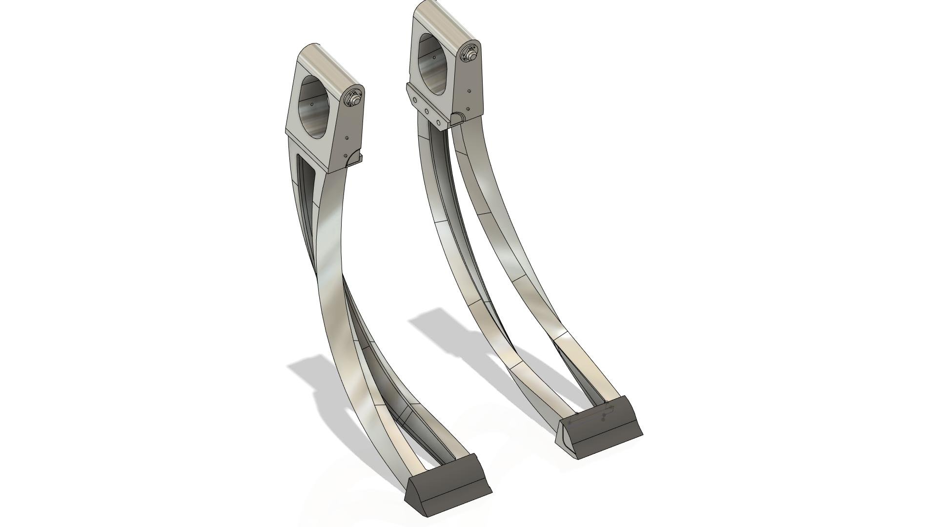
Hi Dennis, The "triangular" parts you mention are known as "chordal brace stiffeners", and I feel your pain regarding these, as they're spectacularly hard to construct in CAD. I think I drew mine over 40 times, and printed 3 different versions - and they're still not completely right! It might be easier to fabricate them from sheet material - perhaps litho-plate as the twist is fairly gentle. I'd suggest a 2 piece approach here as the curves of the channel underneath are different to the twisting of the larger upper piece... Incidentally, the plastic "sight bar" you show from the kit also had some issues. The thickness of the bar is about 30% thicker than it should be, and the arms coming down to the sight are too wide as viewed from gunner's perspective. Finally, you might want to look into the correct curvatures of the ammunition feeds on the FN5, as they should emerge from the front edge of the tanks in the sponsons at an angle of 45 degrees upwards before gradually curving upwards and twisting through 90 degrees. Bullets were in the tanks "nose inwards" so simple inspection should determine if the latter curve is correct. Many thanks for posting the CAD render of the FN20/FN120.
-
Frazer Nash FN5 gun-turrets
Fidd88 replied to Fidd88's topic in LSM 1/35 and Larger Work In Progress
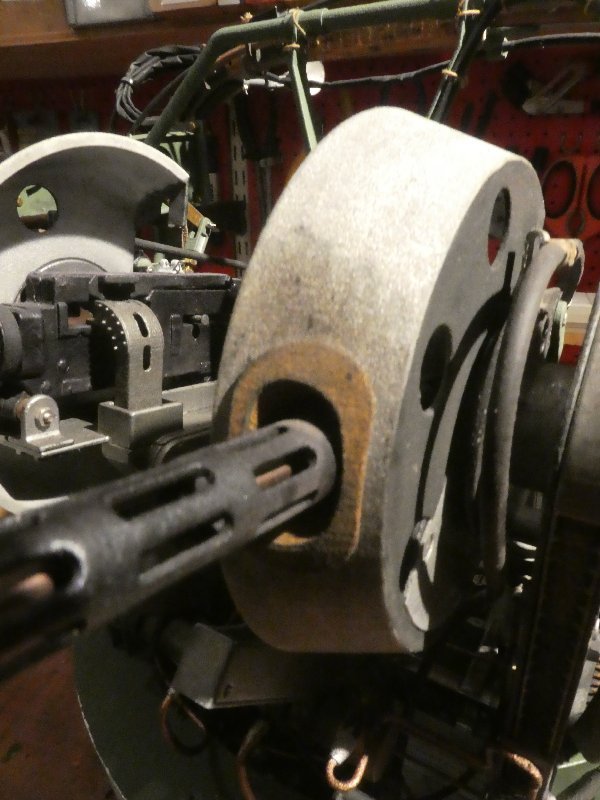
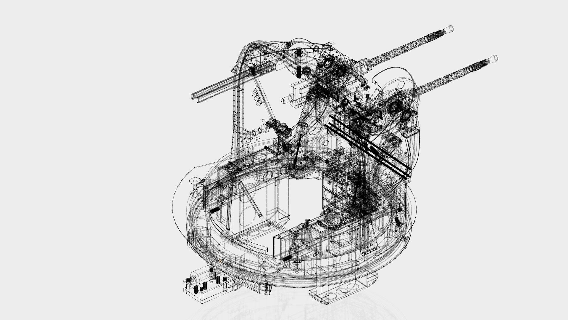
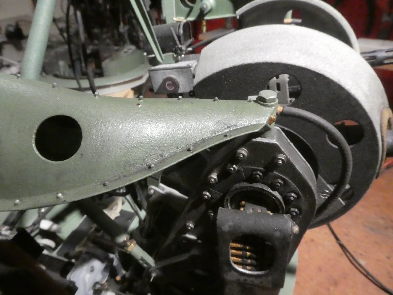
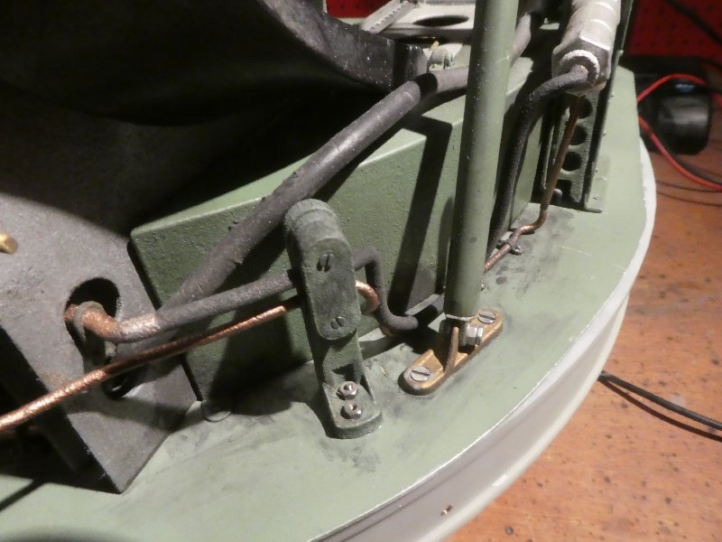
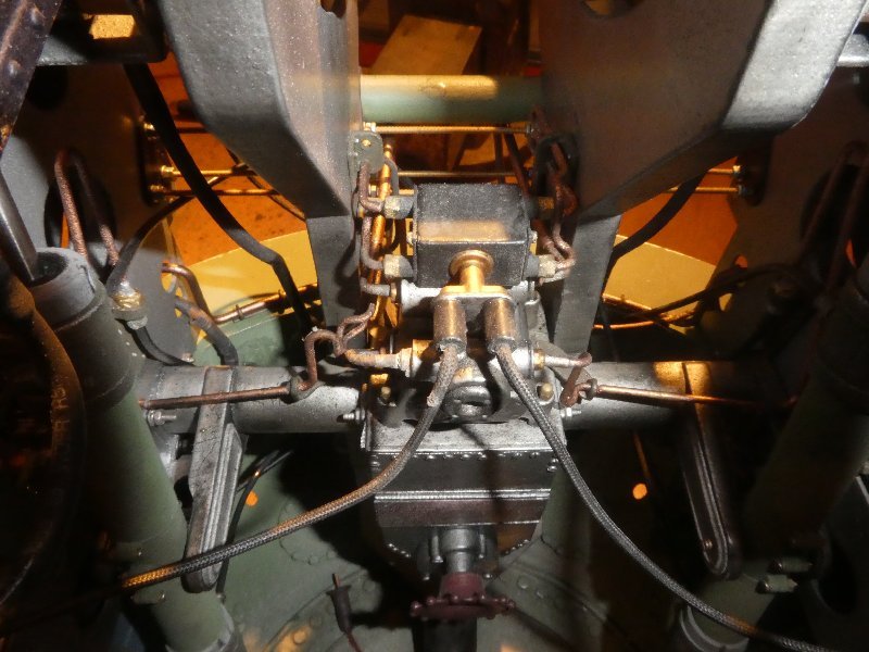
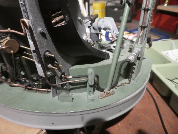
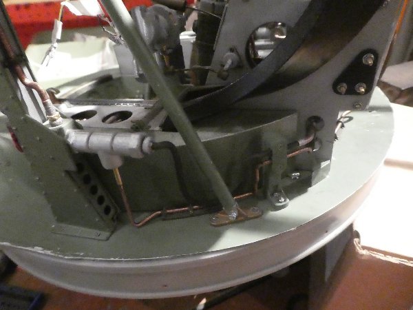
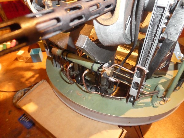
Not much been happening lately, beyond getting a modeling mate over who had a good selection of oil-paints, pastels and pigments, and more importantly the knowledge to apply them. I'd used quite a lot of Alclad "dirt and grime" around areas of the internal turret area which would have been very hard to clean and which probably had some hydraulic-fluid attracting every bit of dust going! We found that methylated spirit, with a drop of washing-up liquid in it, brushed onto the Alclad-painted SLS nylon proved the perfect thing to cause the subsequently applied mixture of water and black/grey pigments to spread well over the area, and then dabbed it back with a little absorbent paper. In concert with the previously applied 'dirt and grime' I think this worked well. A week or so #1 daughter and I exhibited the turrets at the LMA's Gaydon show, and were very busy from circa 10:30am until 4pm when it stopped. The highlight for me was a young Polish lad of about 5, who operated the syringes powering the elevation of the guns grinning all the while. He then asked about the Polish language 'cautions' on the turret doors, and his father explained about Poles flying these aircraft in the wartime RAF, and the lad was completely 'made-up' on digesting this. It was fun to see this education and enthusiasm! As my CNC router still has some as yet undiagnosed fault, I've been trying to find someone local who can cut out the 610mm by 610mm MDF panels to make the initial plug for the mould to vacuum-form the front windows. Things should proceed apace on making the moulds and thence the windows once this occurs. The dirtied webbing straps Chordal brace stiffener with a little muck Front right side, hard to clean for "erks". Central console and supporting metal structure now much toned down with dirt and grime Left-hand ram, ditto general view Front left baffle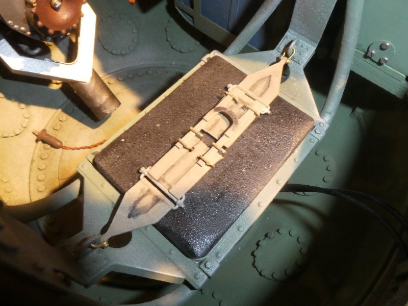
-
Are you going to have a go at motorising this? Faulhaber make some very nice, absolutely tiny electric motors, which can have reduction gear-boxes attached, which are likely small enough to the concealed within the main mast. (6mm OD x circa 20mm length, with reduction gearbox attached). They're pretty pricey, but I've a spare one I could let you have at half-price if you're interested. You'd need to fabricate some form of universal joint I would think, to take the vertical orientation of the motor to the inclined disc of the rotor.....
- 34 replies
-
- 3
-

-
- u-boat scout
- gyro glider
- (and 2 more)
-
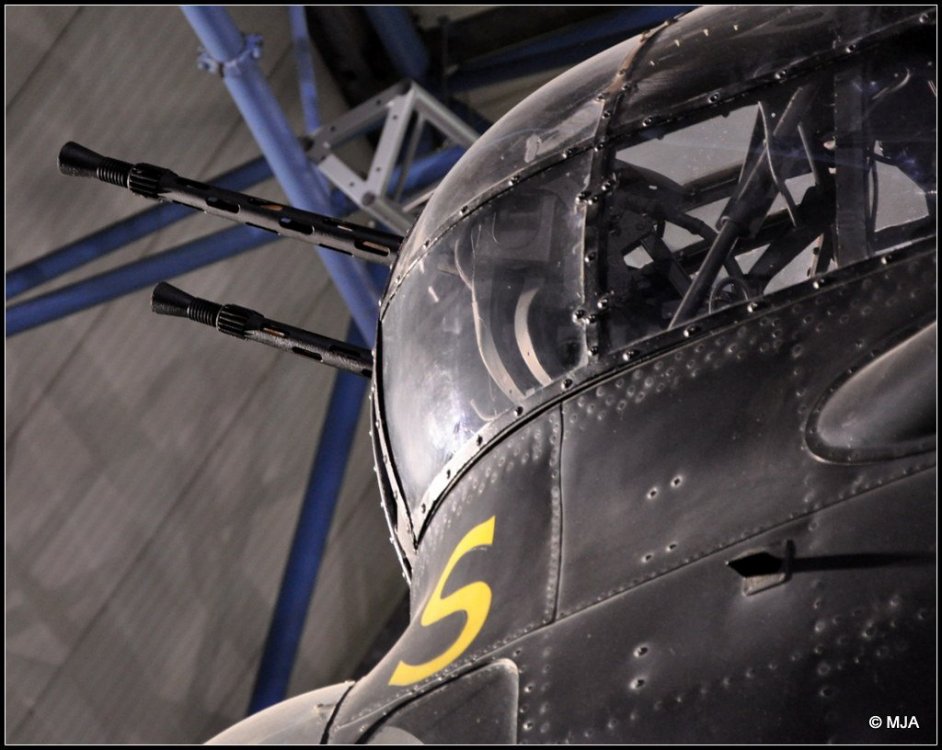
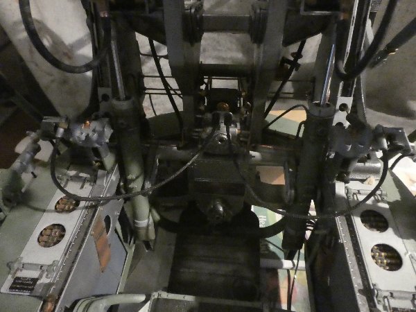
I think the 2nd photo is probably shadow rather than a green, in this instance. The really interesting colour in that picture is that of the guns, I think. I've never seen that before.
-
Hi Dennis, regarding internal turret colour-schemes. Very early FN turrets were bare metal interiors, but before night-bombing became the norm, they were sometimes painted internally a green-grey, however this seems to be a hit and miss affair, as one can often find single aircraft with turrets in both schemes. I don't think the grey-green scheme lasted long in '41. Soon after night bombing commenced an all black scheme became the standard, however, turrets in both bare-metal and grey-green can occasionally be seen long after the schemes were officially superceded. Additionally it's often hard to distinguish the two from black and white pictures. My guess is that if turret output was being outstripped by demand, they simply omitted painting them before they left the factory, and such supplies of the grey-green paint as still existed when the official scheme went to all black were used until expended, with squadrons dealing with unpainted interiors if time permitted.
-
Glad to be of help. Of course, there are other diorama possibilities for showing off the internal structures, such as having a brewed-up tank with the turret laying beside the hull, or as a factory-floor diorama with the tank 'under construction' - a diorama I've never seen done, oddly.
-
You know seeing this interior detail, makes me wonder if the model turret should be removable, or perhaps held away by a crane or winched up.... Incidentally, regarding the nose-heavy gun, as an alternative to blutak above the breech to limit depression of the metal gun tube, you might consider counter-weighting it by drilling holes into the breach from the loading end and filling them with lead-shot and PVA or similar, once correctly counter-weighted, the holes can be filled and painted over....
-
1/18 P51C Mustang "Lopes Hope 3rd"
Fidd88 replied to airscale's topic in LSM 1/35 and Larger Work In Progress
Not that I'm at all what you might call a 'David Lean', when making videos, nor indeed am I much of a fan of modern social media (I neither "face-book" nor "twit", "text" nor "selfie") but making and uploading video's is a complete doddle, and takes no time at all once you've figured out the first one. I don't think the state of your bench is a bad thing - for people to see the tools you have to hand, and the way you clamp the work, or polish parts or offer parts for fit is all absolute gold-dust to those who wish to attempt to emulate you. All I do really is to natter about this or that on my models and draw attention to things that worked well, things that didn't, (always useful to some), and what's left to take care of. I use my wife's digital stills camera in video mode, in macro zoom mode, and then take the file off the cameras SD card and into a folder on my pc from where it's uploaded to youtube. Easy as pie. If you'd like to take and upload a test video, pm me and I'll walk you through it on the telephone, if you like. Your techniques and ability are really extraordinary, and tutorials will I think, be very popular and useful to modellers. -
1/18 P51C Mustang "Lopes Hope 3rd"
Fidd88 replied to airscale's topic in LSM 1/35 and Larger Work In Progress
Just beautiful. Thanks for the advice on PETG. My turrets really require two or three different moulds, one for the front panels, which go to 60 degrees either side of straight ahead, and one for the "glazing" that goes from those points aftwards as far as opaque 'quarter-panels' (as I call 'em) which lie either side of the doors. These are simply mirror-images of each other, so can be done on 1 mould and cut else 2 moulds. The current plan is to cut MDF layers in the manner of contour lines, fill the gaps with resin and micro-balloons, sand back and glass with very light fibre-glass, re-sand and seal. Then female moulds can be made and those then casted with alloy-resin (incompressible when hard), and then that forms the mould over which the panels are vacuum-formed. As I intend using either 1mm or 0.5mm acrylic, your method is looking an attractive alternative! I'm really looking forward to seeing your model finished! -
1/18 P51C Mustang "Lopes Hope 3rd"
Fidd88 replied to airscale's topic in LSM 1/35 and Larger Work In Progress
LOL. I ought to have "twigged" that, I fitted brass bracing parts to the cupola of my turrets to help them resist aerodynamic loads - made via photo-etching. 'Scuse me lads, having another "senior moment"! -
Sorry about the confusion, Okay, what I think we're looking at in the lanc pic above is a later iteration, and I think it looks like this, possibly with short joining stretches to keep the runs parallel and correctly spaced. Without getting a good look at the actual turret I can't be sure, but knowing how the guns have their belts drawn up the chutes with the arming wire, it's hard to see how this could be achieved without the side facing the gunner being open to view. Again I've thickened the chutes to make them printable.
-
LOL. What an idjit I am, I've only just noticed that the one fitted to the lanc above are different to mine, in that the open edge of the feed is on the outboard edge towards the top, which has completely weirded me out. This would mean the rounds were not visible to the gunner as viewed from his seat, and in turn would make it much much harder to feed the rounds from the tanks to the guns when initially loading. This has me completely foxed now. I took the design of mine from an RAF instructional film. I'll look into this further and get back to you.
-
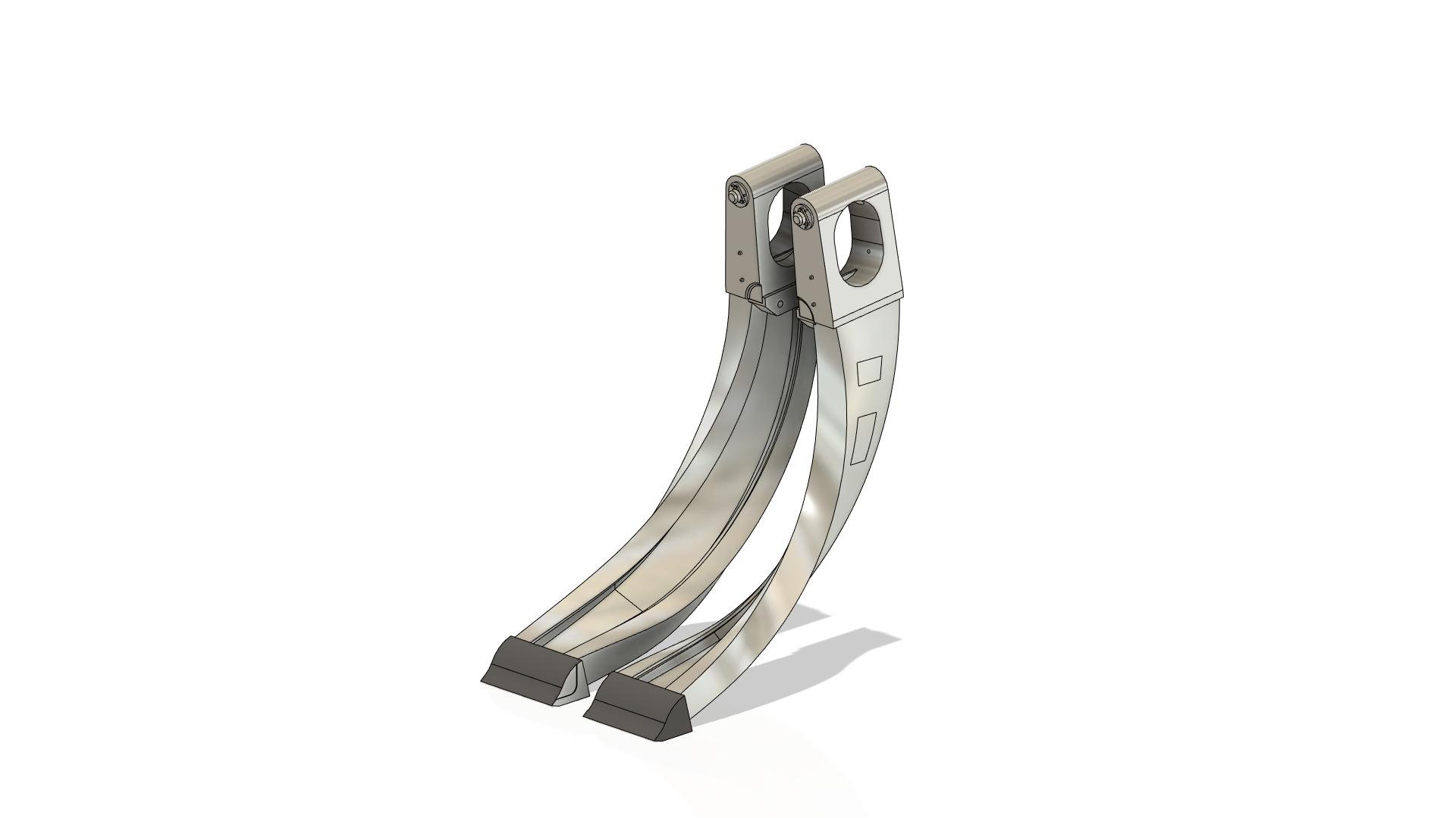
Wingco57, I've done a "fast and dirty" rework the CAD drawing of chutes I know to be correct for the FN5, and as far as I can tell they're correct for the FN5a as fitted to your Manchester. The rework has consisted of making them much "thicker" in terms of the material so it has half a chance of being printable in Nylon at your scale. Or you can just use them for reference to scratch-build by other means, if indeed you wish to. Rescaling them to match the scale of your model is a moments work. What would help in this regard is to know what the height of them is, using the top of the ammunition tanks as the bottom reference, and the top of the chute as the other. I can then rescale it, so they will definitely appear the correct size to yours. As I often am submitting stuff for printing, I could 6 or so of these and just pop them in the post - if you wish. Please don't feel compelled to do so! Anyway, here's a picture of the thickened chutes left and right-handed, I figure you might need 3 or so pairs, assuming the front and mid-upper turrets have the same problem, plus a couple spare. If memory serves, the Manchester has an FN4 or FN4a In the rear, and I'm not familiar with the chutes in that turret. Drop me a pm if you're interested in having these done?

-
1/18 P51C Mustang "Lopes Hope 3rd"
Fidd88 replied to airscale's topic in LSM 1/35 and Larger Work In Progress
The thing about watching Peter's work on the model, I feel, is that you start to look at both the model, and the full-size aircraft in a very different way to normal. Instead of the just the form of it, you start to see all the tiny features that Peter noticed and replicated, and then check for their presence on the aircraft and then vice versa. Ordinarily I'd never have noticed what I take to be stiffeners or some early form of countering wake-vortices (?) in the trailing edge of the outer-wing, just forward of the aileron, on the P51. Looking at the model has made me realise what a clever design the P51 is from an production engineering design too. Essentially it's a "Spitfire", redesigned for speed and endurance, but it also largely does away with the plethora of hard-to-fabricate compound curvatures, or greatly reduces the degree thereof. I'd be willing to bet that the wing was similarly much easier to build on the P51 (on the full-size aircraft) relative to the Spit? Peter, using your "boiling water" method, how large a piece of acrylic do you think can be formed over a plug? Can you tell us a bit more about that process? A real joy to watch, I was utterly captivated seeing the metal framed windows coming together! -
Frazer Nash FN5 gun-turrets
Fidd88 replied to Fidd88's topic in LSM 1/35 and Larger Work In Progress
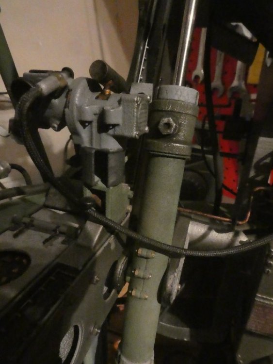
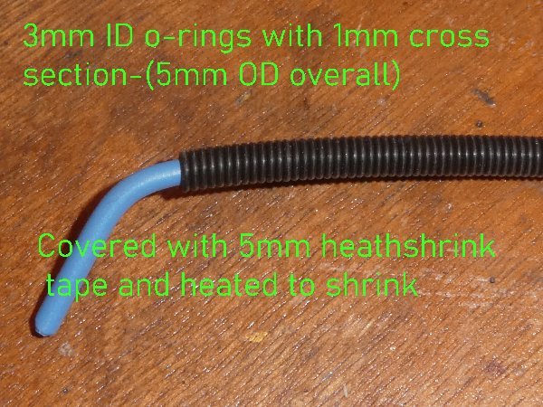
Re-reading my post above, I forgot to mention that in picture #2 (middle of 3) you can see the 2-3mm spigot of wire+insulation+shrunken tape that I left before the start of the O-rings. Having the tape longer than the rings obviously helps stop them from moving. It wasn't possible to achieve the hoses without the tape, as the O-rings attract dust and stray hairs like you wouldn't believe. This was more or less essential to be able to glue on metal tubes without the latter appearing over-size. Although the K and S metal tubes were nominally the correct ID (internal diameter) to take the "spigot" I found it necessary to drill out the tubes a little from 3.69mm (or thereabouts) to 3.8mm iirc, which as you'll appreciate is pushing it a bit as the wall-thickness is only .14mm. However it can be done on the pillar-drill, but a machine-vice is most necessary. Proxxon do some really great little machine-vices for about £60, which I use all the time. The tubes were drilled to a half depth, so that the small brass tubes would fit nicely into the undrilled portion. -
1/18 P51C Mustang "Lopes Hope 3rd"
Fidd88 replied to airscale's topic in LSM 1/35 and Larger Work In Progress
Crikey Peter, this is a masterclass. Have you ever considered making some tutorial films on youtube? Also, pardon my ignorance, but what is "PE"? Cheers, -
Frazer Nash FN5 gun-turrets
Fidd88 replied to Fidd88's topic in LSM 1/35 and Larger Work In Progress
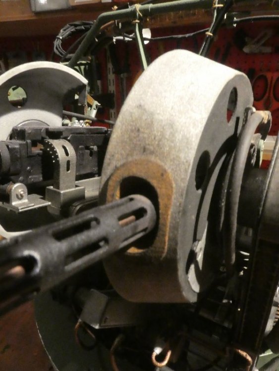
Blimey. Well I'm glad you chaps are enjoying the builds as much as I have been. Seeming as you are still, here's a picture or two of making the ribbed hoses with O-rings and heat-shrink tape. I think for anything smaller than 5mm OD, I'd strongly recommend shrinking the tape over 3d printed ribbed hose, instead of threading o-rings, as the effect is really a bit too subtle. You'd laugh if you knew the lengths I go to to avoid having to do mathematics! There was some simple geometry involved in getting the elevation and depression, and getting the sight-bar to remain parallel to the guns via the swinging arms and pushrods. But that's about as nasty as the mathematics got. In the pictures below, the finished hose is approximately 5.2mm max OD. The "Ballooning" was caused by the O-rings or insulation getting too hot and generating gas in a localised pocket. On the next attempts I did not try to shrink all the tape in one session, but let it cool between passes with the soldering-torch, which prevented further gas pockets forming.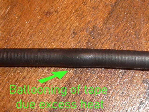
-
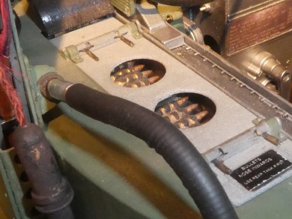
I think you might want to research the ammunition feeds on the FN5a turret, they look very odd to me. On the FN5 turret (taller one without the "waisted" rear, as fitted to Wellingtons) the feed curves upwards from the horizontal, initially, from the tanks, then twists though 90 degrees. Rather than exiting the tanks vertically before curving to the horizontal and then twisting. If you take a look at my thread on FN5 turrets you'll see the correct structure, although the Manchester probably didn't have the rectangular slots in the outer face which were a squadron adaption. If you like, I can adapt the CAD drawing for mine (to thicken the material) and let you have an .stl file that could then be printed... Edited: This is the clearest shot I can find of an FN5a from a Lancaster, which I think demonstrates the correct curvatures of the ammunition feeds. Looking at the FN50 (Lancaster mid-upper), the feeds are likewise horizontal initially climbing and twisting progressively as they approach the guns. I cannot - so far - find any Frazer Nash turret with the feeds as supplied with your turret model. Looks like a manufacturing error. I hope this helps.
-
Frazer Nash FN5 gun-turrets
Fidd88 replied to Fidd88's topic in LSM 1/35 and Larger Work In Progress
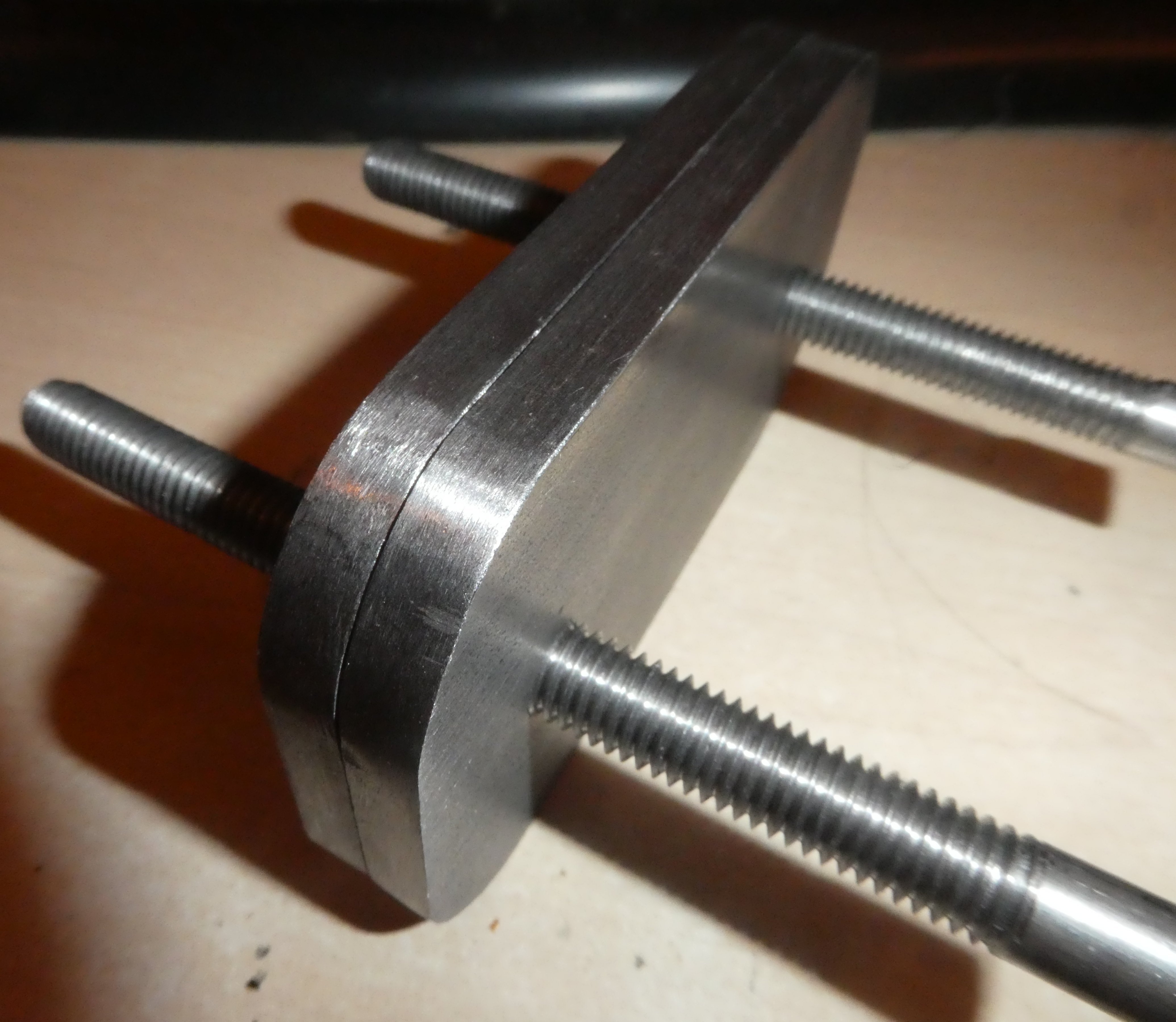
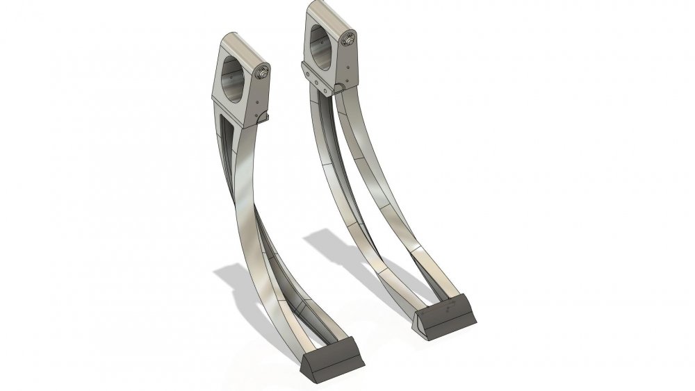
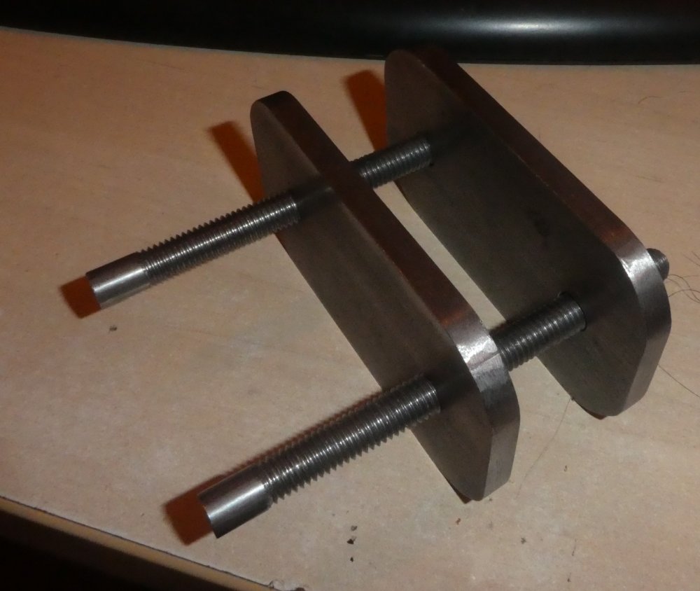
Cheers, I really only needed half those, so the remaining lengths are now salted away for future use, Actually I spent a very agreeable couple of hours listening to Classic FM on the wireless and sculling coffee as I did the 600 rings. The effect is 'good enough', but not, I fear, 'great' as far as the ribbed hoses go. Still, it was a fair stab at it, I'm glad you've enjoyed following my "triumphs and disasters" as Kipling puts it, as the turrets neared completion. Frankly there'll not be anything else to report for some considerable time now, but I might post the odd update as the mould-making for vacu-forming the Perspex gets going, except maybe the front-turret "tub" which is a bit more interesting than the one for the rear. I'll certainly be keeping an eye on all your incredible modelling projects here, If anyone needs parts drawing in CAD, at any scale, let me know, and if needbe I can advise on whether or not the part is viable to print in SLS Nylon. It's occasionally nice to do something not Wellington or turret related! I'm also pretty knowledgeable on the Wellington airframe if you need questions answering. Thanks all of you for all your kind words, as you know modelling is a solitary battle conducted in sheds, so it's great to have had some feedback after years of boring the family to tears with the minutiae of turret-design! Still, some of it has 'rubbed off' as my daughter has just started an engineering apprenticeship, and came home with this that she'd made from steel rods and plate at the end of week 1. All parts are hand-filed by her with no observable "rounding" from the file being out of square to the work. Impressively if I reversed one of the two plates on the threaded rods, both the two hole centers, the four edges, and the four radii remain perfectly aligned! Easy to make, hard to make this well. She's also the only girl in 41 other apprentices! (Dead chuffed Dad)
-
Frazer Nash FN5 gun-turrets
Fidd88 replied to Fidd88's topic in LSM 1/35 and Larger Work In Progress
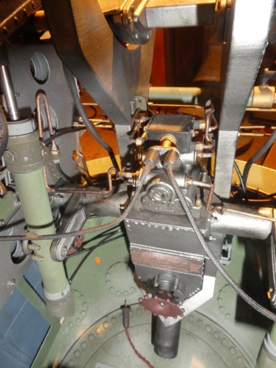
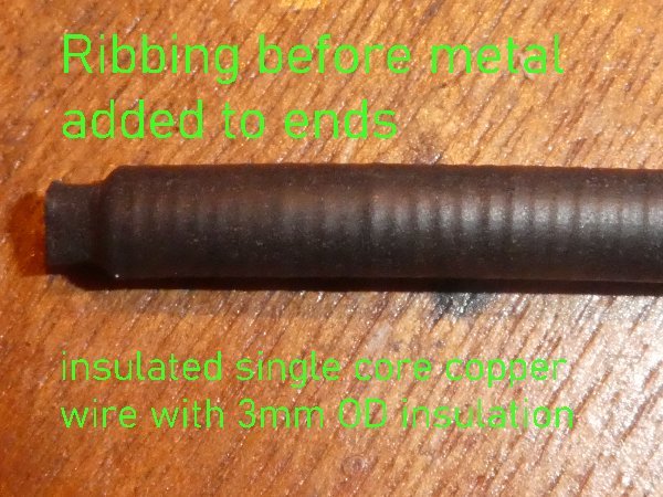
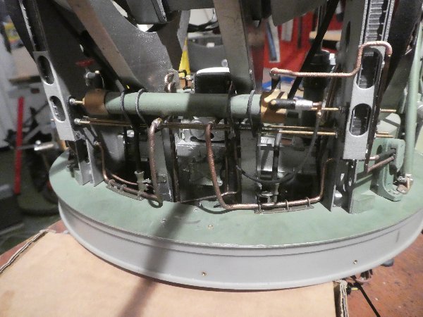
..and a few pictures of the newly made an installed oxygen pipes. One plain one goes from the economiser in the bottom of the turret to a fitting in the port stanchion (front turret) and then a ribbed or "corrugated" one goes from the fitting to the gunner's oxygen mask. The ribbed one was made by taking single core electrical cabling with 3mm OD insulation, and then threading 600 O-rings of 3mm ID and 1mm cross-section (5mm OD), all then having heathshrink tape warmed to close over it, the o-rings providing the effect of the ribs. It did work, but the effect is a little too subtle.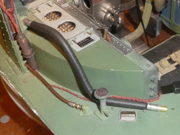
-
I do hope my post was not interpreted as "I think this blue/green is wrong", rather, I was trying to illustrate the need for caution when considering old colour photographs, and especially wartime era ones, as an "authority" as to hues. As the similar effects act on both paint and pigments in fibre-glass, or indeed pretty much any coloured material, it therefore follows, I suggest, that similar caution needs to be taken with any reference material of age. Photodegradation was explained to me many years ago as a young glider-pilot when I asked one the old-boys in the workshops why it was that our doped-fabric gilders were colourful, but the newer fibre-glass jobs were invariably white overall. I've been waiting 30 years for the opportunity to pass on the knowledge!
-
Lovely build, you chaps are so talented on the painting and miniature detailing. I was interested to read the great RM74 paint colour debate on the link above. I think one has to be very cautious using wartime colour photographs or paintwork to inform choices as to what the correct shade is, especially if it is thought that "a green should be more blue" as mooted in the linked thread. The first thing to note is that wartime colour photographic film was usually used in cameras built to take pictures on black and white film, and so really until the 1960's lenses were not optimised for colour film use. Secondly, because of shortages and lack of refrigeration, colour film tended to be older before use, and degraded by sub-par storage. Developers and fixers were somewhat over-used for similar reasons. (Robert Capa lost nearly all his pictured from Omaha beach due to this over-use) So, relying on the "true" colour from a wartime photograph is dicey to start with. Secondly, the photographs and indeed painted wreckage cited in the thread above, are liable to "photodegradation", which is essentially the science of how colours change over time. Different materials and colours can change to a greater or lesser degree, and the wavelengths of the light causing the photodegradation also affect to what degree and in what manner colours are changed. However, by and large, the longer the wavelength of the reflected colour, and the shorter the wavelength of the light causing the photodegradation, the more pronounced the degradation is. So, reds (longwave) being kept in strong UV light (short-wave) causes the maximum effect. This is why you generally do not see red pigments used often on boats or gliders gel-coats, as this red would fade to pink and change in hue most readily. Blues however, are a much safer bet for these craft, and white is best of all. If we consider the RM74, said to be a "grey-green", and disregard the grey, then it can be readily seen that a reduction in the yellow hues (adjacent to red in the spectrum) will cause the green hues to appear bluer (as green is a mixture of yellow and blue) - leading to the 'spirited' debate as to the true colour of RM74 in the linked thread!
-
Frazer Nash FN5 gun-turrets
Fidd88 replied to Fidd88's topic in LSM 1/35 and Larger Work In Progress
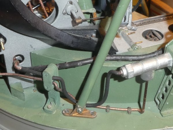
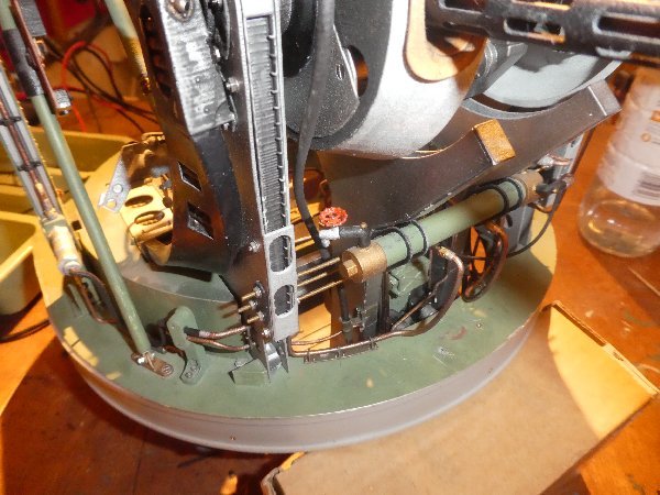
A few more pictures of the cosmetic hydraulic lines now glued in situ. Very bloody fiddly, if you'll pardon the pun. Next job is to restore the pneumatic lines, then the front-turret will be as complete as it can be with the parts I have. Following that I'll be working on the rear-turret to remove the pneumatic lines temporarily, fit the hydraulic lines and then restore the pneumatic hoses. After that, the initial plug for the fabricating the windows in 0.5mm sheet Acrylic, and at some point fitting the two "tubs" for the turrets. I'll probably make some form of temporary stand for them to display in the house, unless she-who-must-be-obeyed happens to spot them!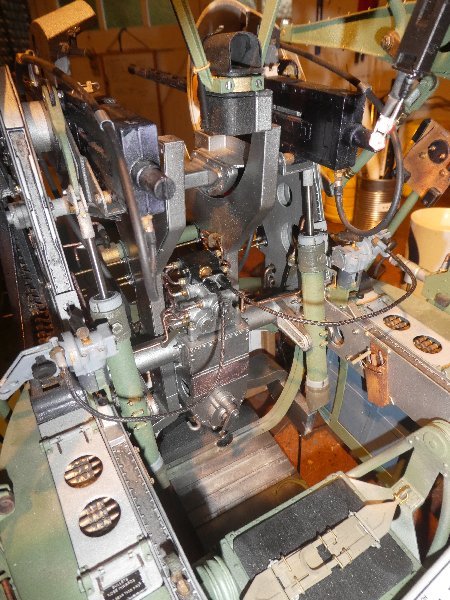
-
Frazer Nash FN5 gun-turrets
Fidd88 replied to Fidd88's topic in LSM 1/35 and Larger Work In Progress
Well I'm very happy to assist, either in queries about fusion 360, or simply drawing your (or anyone's) parts and preparing .stl files for uploading to a 3d printer. It's usually a pretty quick process. For a demonstration, the other day, I drew a fairly accurate caged electric-fan, and it took about 15 minutes to do and another 2 to ready the .stl file and upload it to a printing site. Of course when you first learn expect it to take a great deal longer! One thing our American cousins will have to take into account is that most printers are configured to work in metric (mm), rather than Imperial, and so your drawings would likely need to be rendered in metric mm as well. It may be that US printing services do offer Imperial, but please check before you start. Fusion can be configured to either, and having configured it, all further drawings remain in the configured measurement system.