
JeroenPeters
-
Posts
4,904 -
Joined
-
Last visited
Content Type
Profiles
Forums
Events
Gallery
Everything posted by JeroenPeters
-

1/32 Ju-87D Stuka
JeroenPeters replied to JeroenPeters's topic in LSM 1/35 and Larger Work In Progress
Here we go. A bit overdone, but I'd rather have too much expression and sand it away, than the other way around.
-
1/32 Ju-87D Stuka
JeroenPeters replied to JeroenPeters's topic in LSM 1/35 and Larger Work In Progress
Turning my attention to to the prop blades. These are the VS111 as used on most late Ju-87D's and later models. They were all wood and are a variation on the VS11 that were also used on the Ju-87D. Blade length is approximately 1480mm and diameter of the prop-circle was about 3260mm. I'm writing this mostly as a note to self It's difficult to get decent profiles, but I think this looks ok. Both the Hasegawa prop and Trumpeter's are of incorrect shape. The more I dig in the Trumpeter kit, that at first sight appears to be more detailed, the more I like the Hasegawa kit. The Trump kit has way to simplified detail and shape guessed interior and engine. Using decals on the prop blades is more correct than spraying them. You might want to deliberately achieve to silvering These VS111 blades were fixed and not variable. Only thing I need to find is the exact angle they stood. And I need to draw the wave shaped metal protection strip at the leading edge.
-
1/32 Ju-87D Stuka
JeroenPeters replied to JeroenPeters's topic in LSM 1/35 and Larger Work In Progress
Gotta have the Yahu ip’s. Luckily my local hobby store had 2 in stock
-
1/32 Ju-87D Stuka
JeroenPeters replied to JeroenPeters's topic in LSM 1/35 and Larger Work In Progress
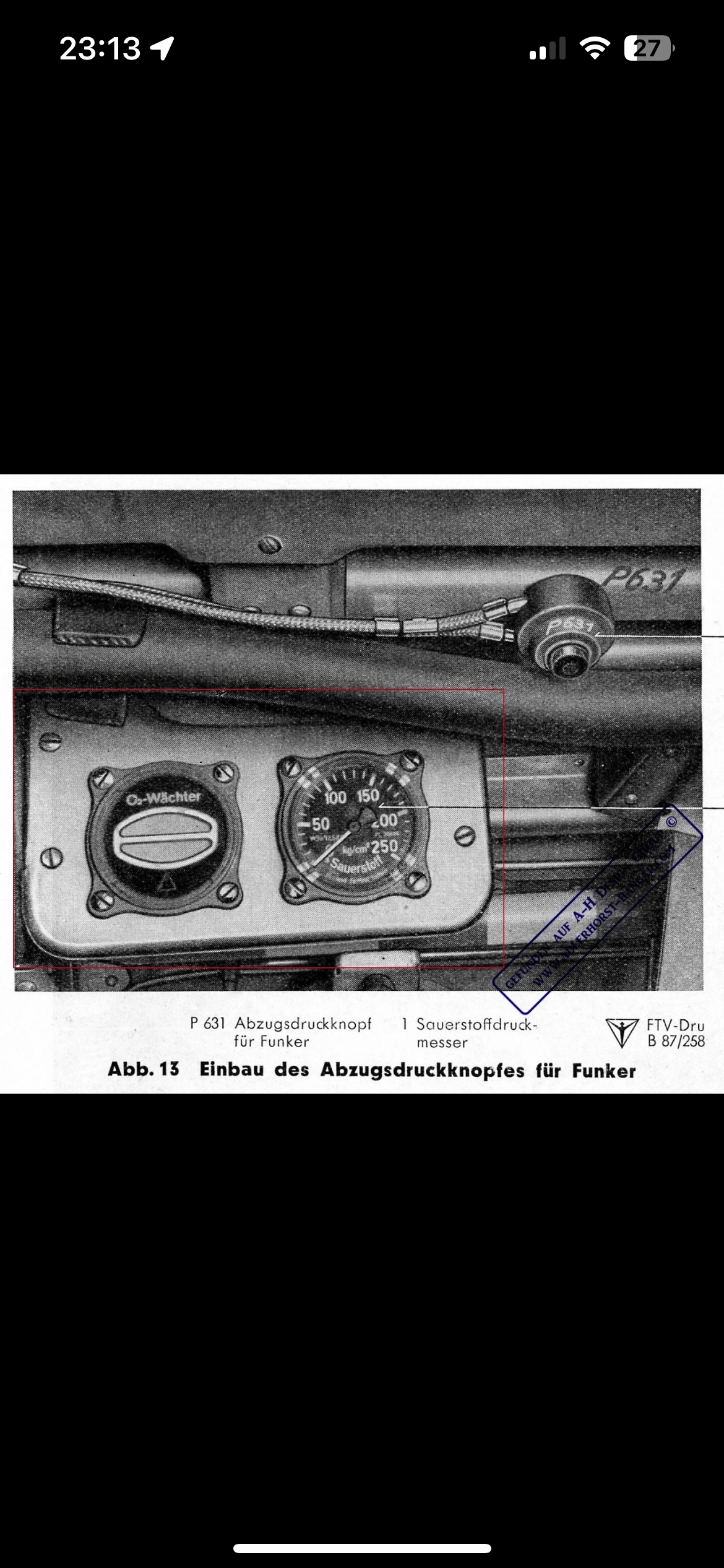
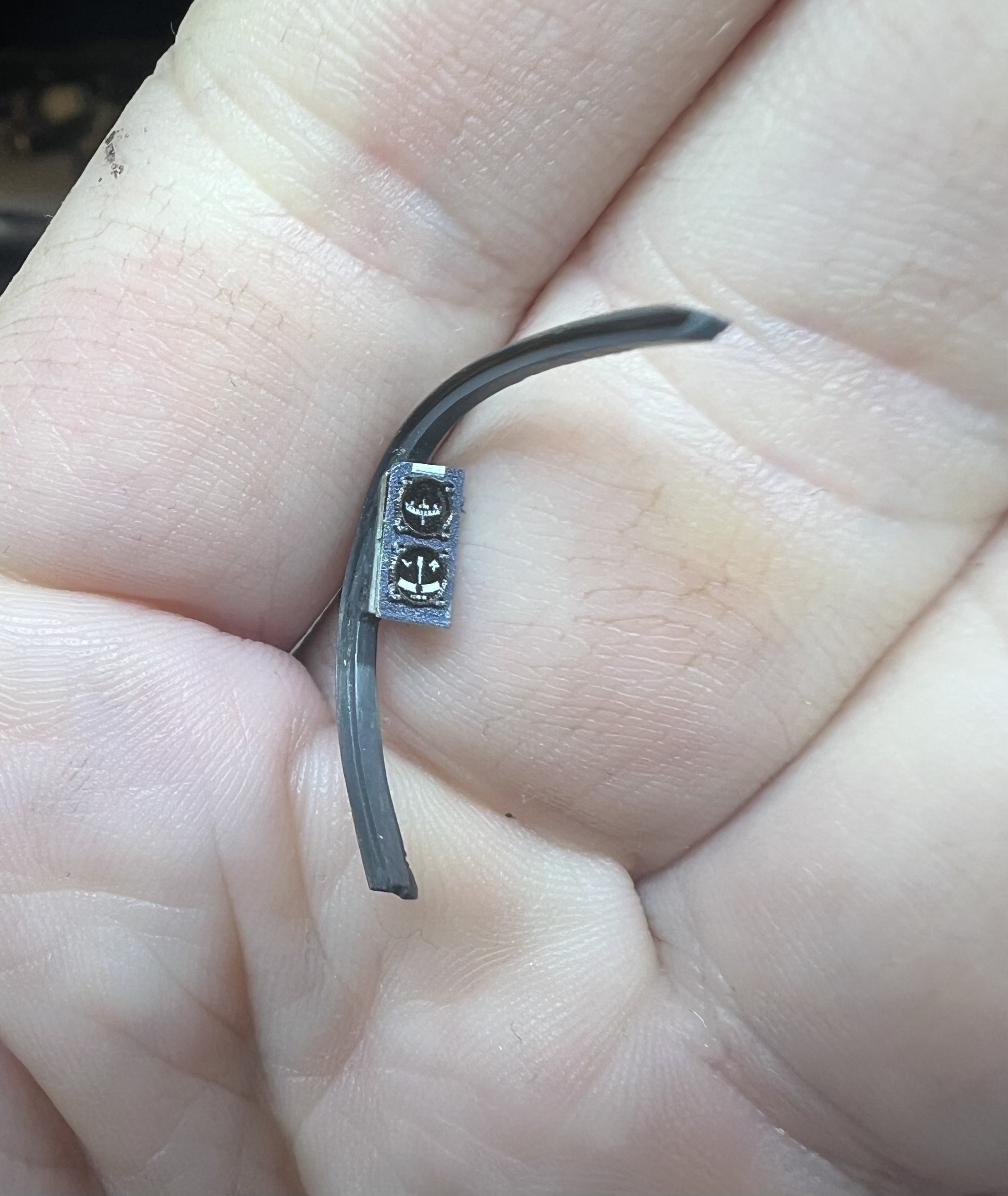
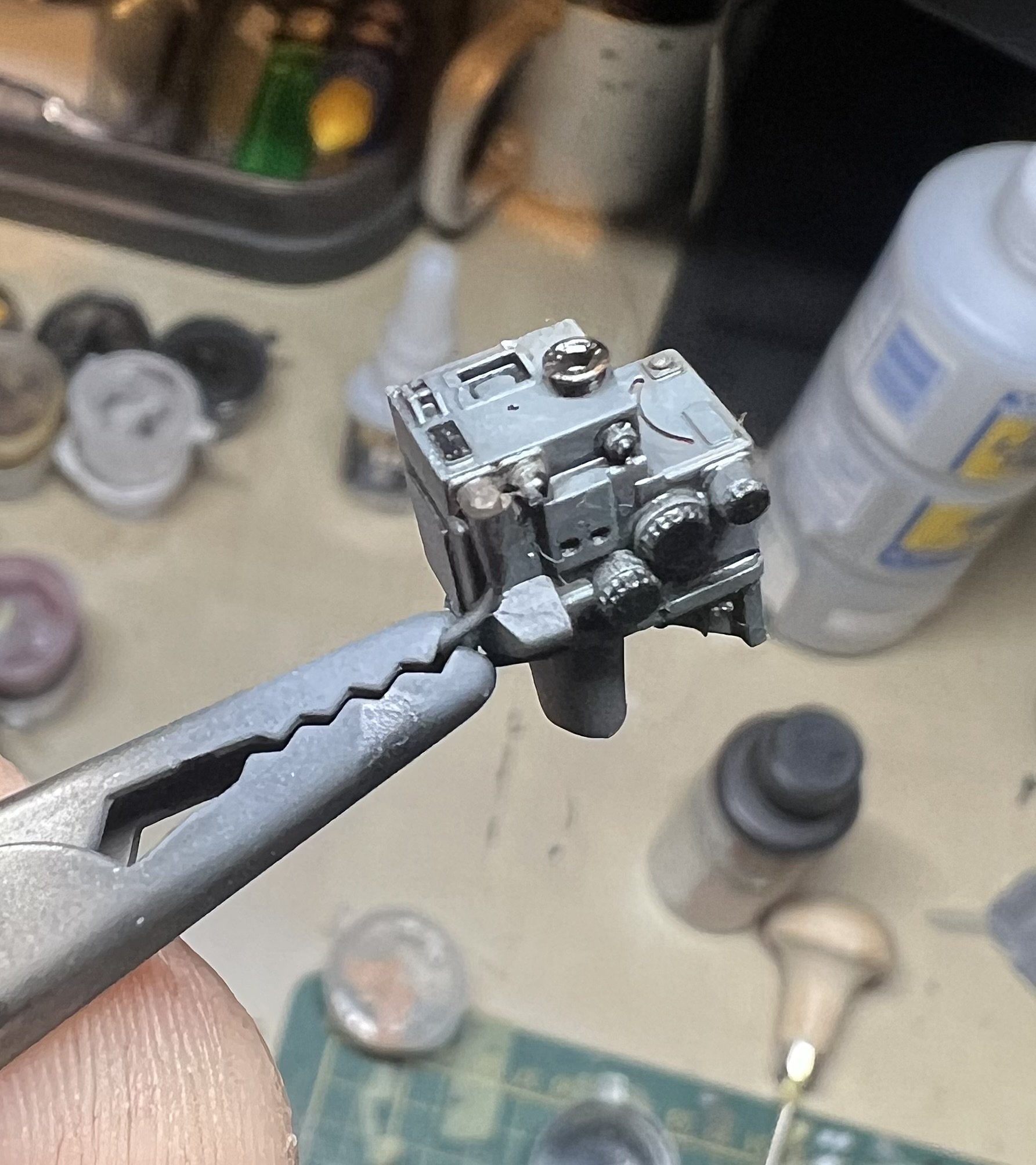
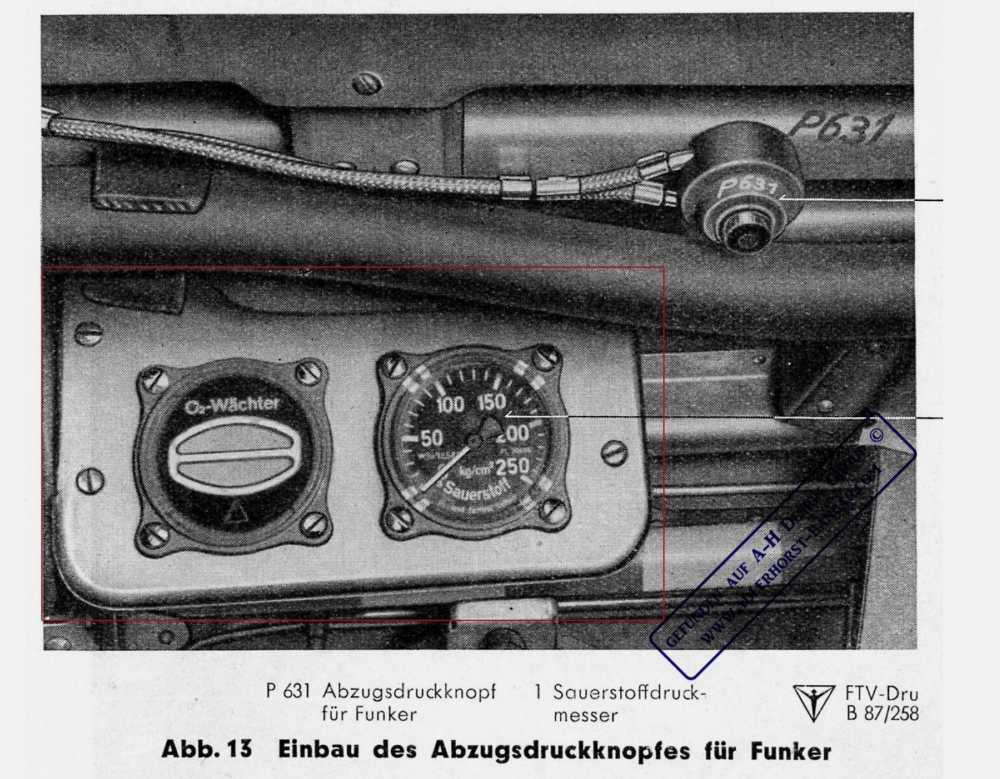
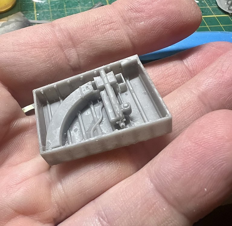
Perfect. Original oxygen panel. Might have to change the pressluft gauge, but will have to look for a proper dial. For now this is fine.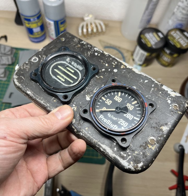

-
1/32 Ju-87D Stuka
JeroenPeters replied to JeroenPeters's topic in LSM 1/35 and Larger Work In Progress
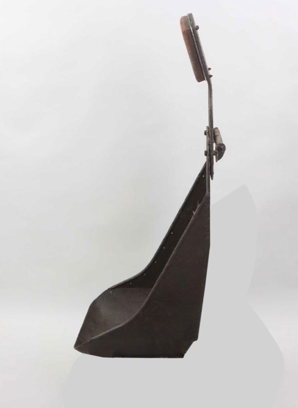
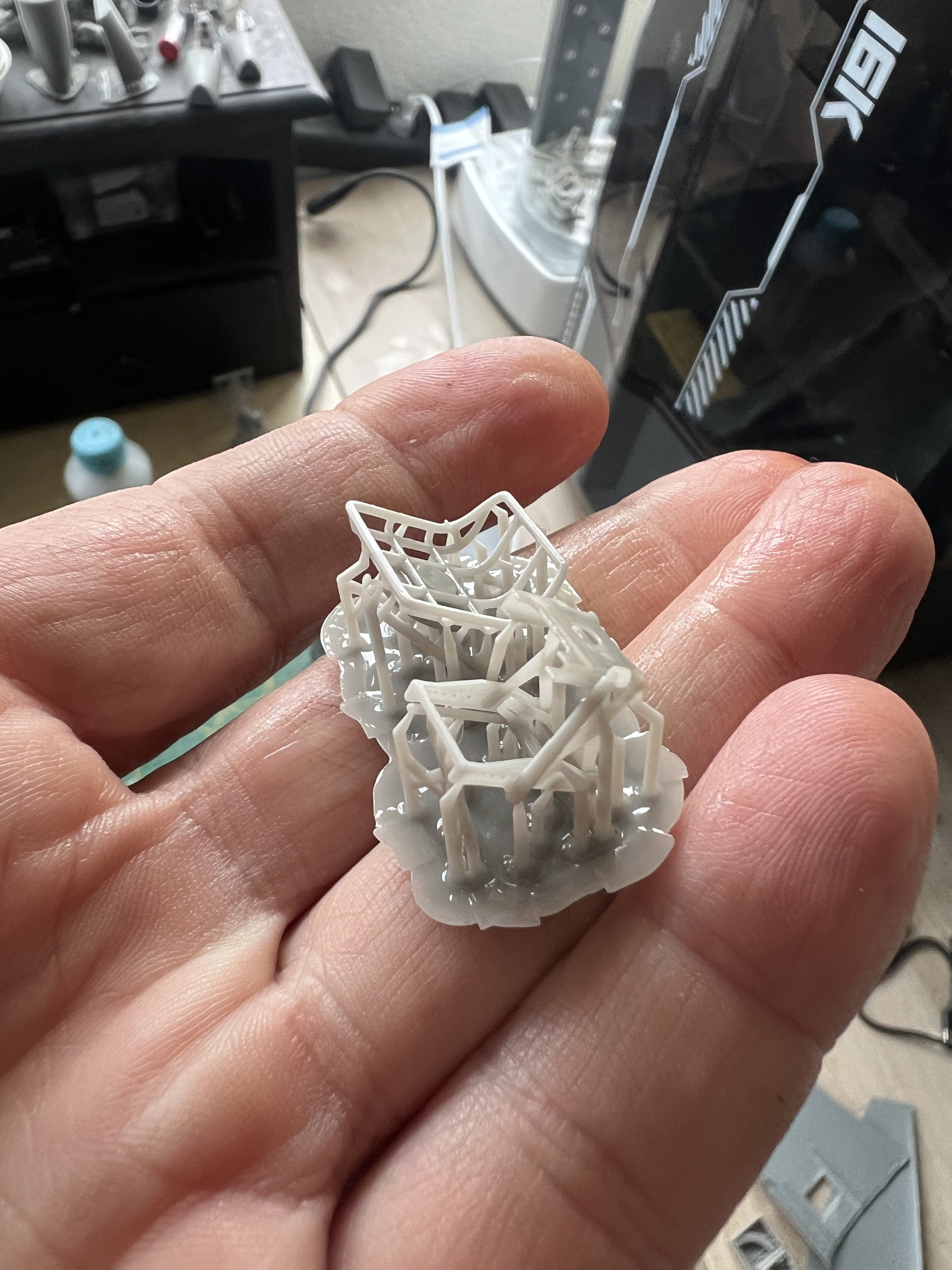
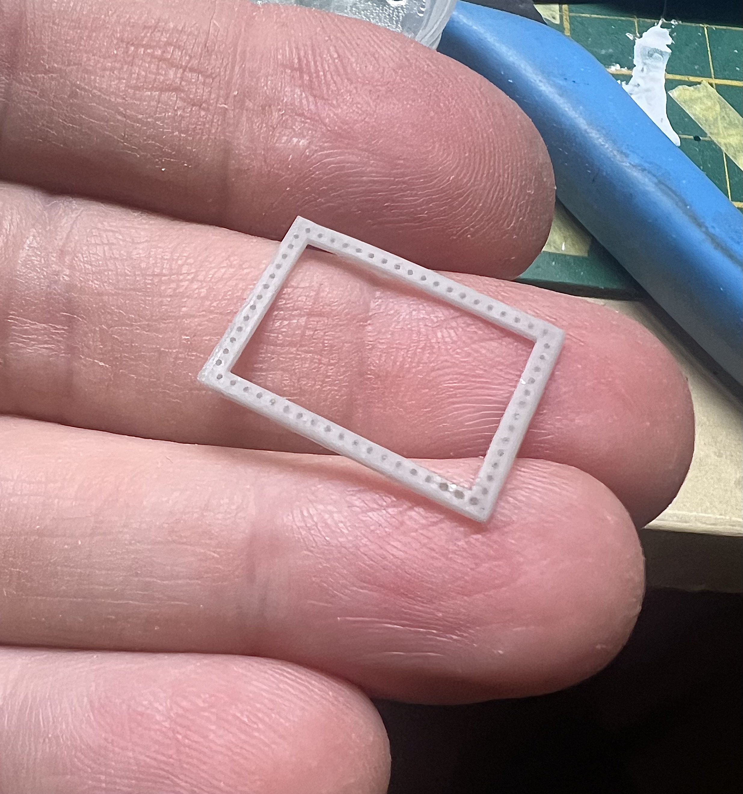
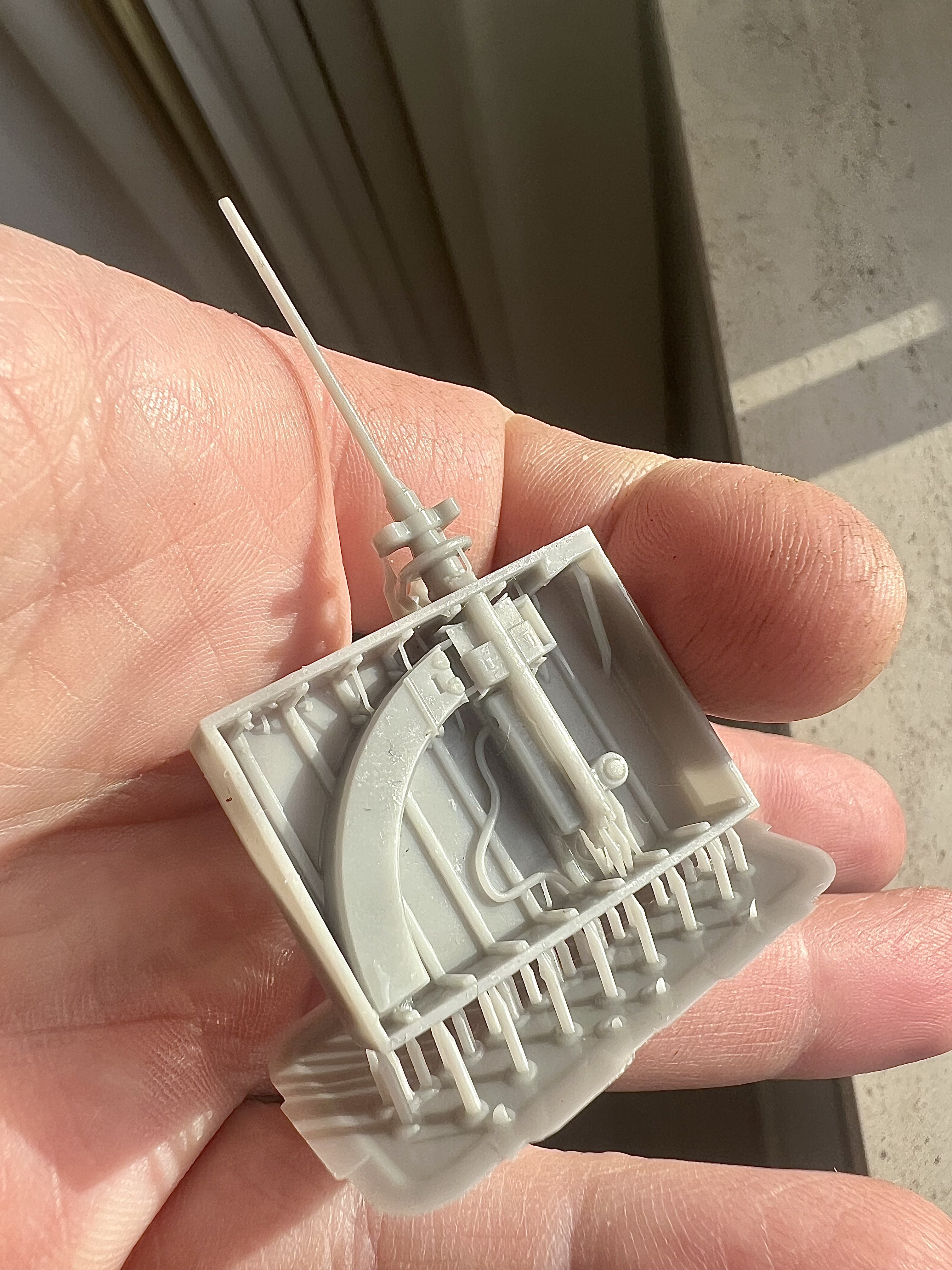
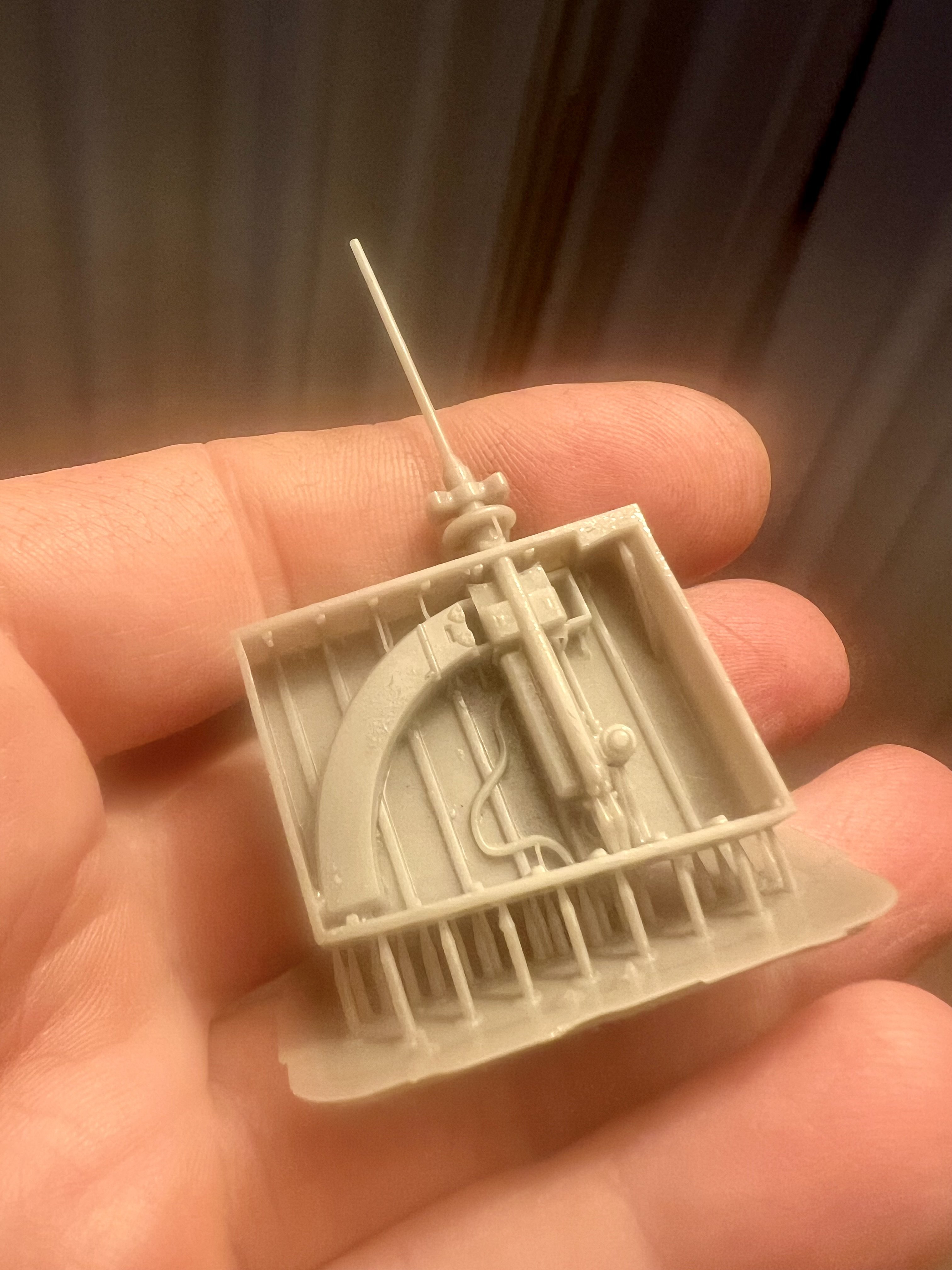
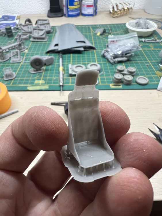
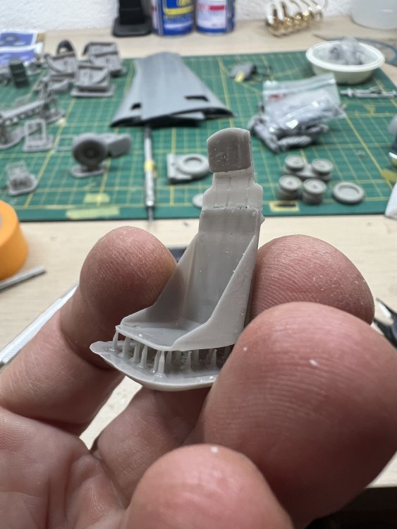
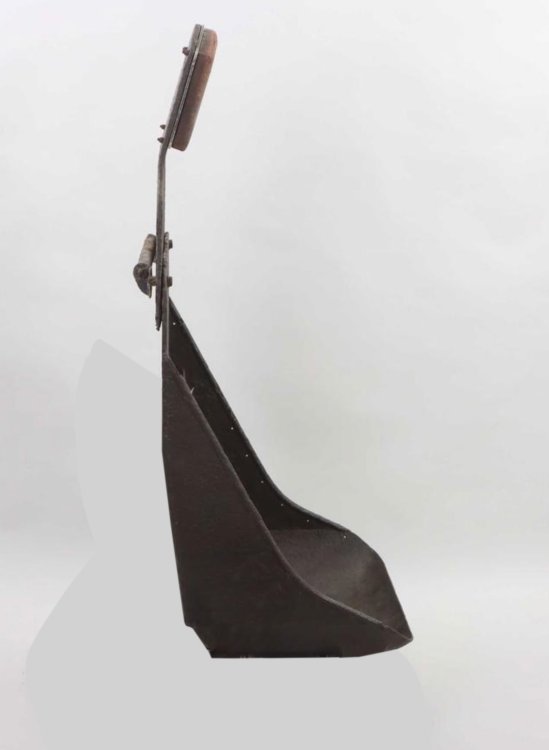
Fresh from the printer The seat thickness is real to scale so… paper thin and fragile.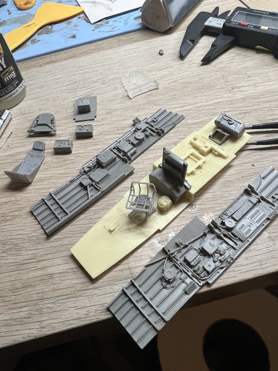
-
1/32 Ju-87D Stuka
JeroenPeters replied to JeroenPeters's topic in LSM 1/35 and Larger Work In Progress
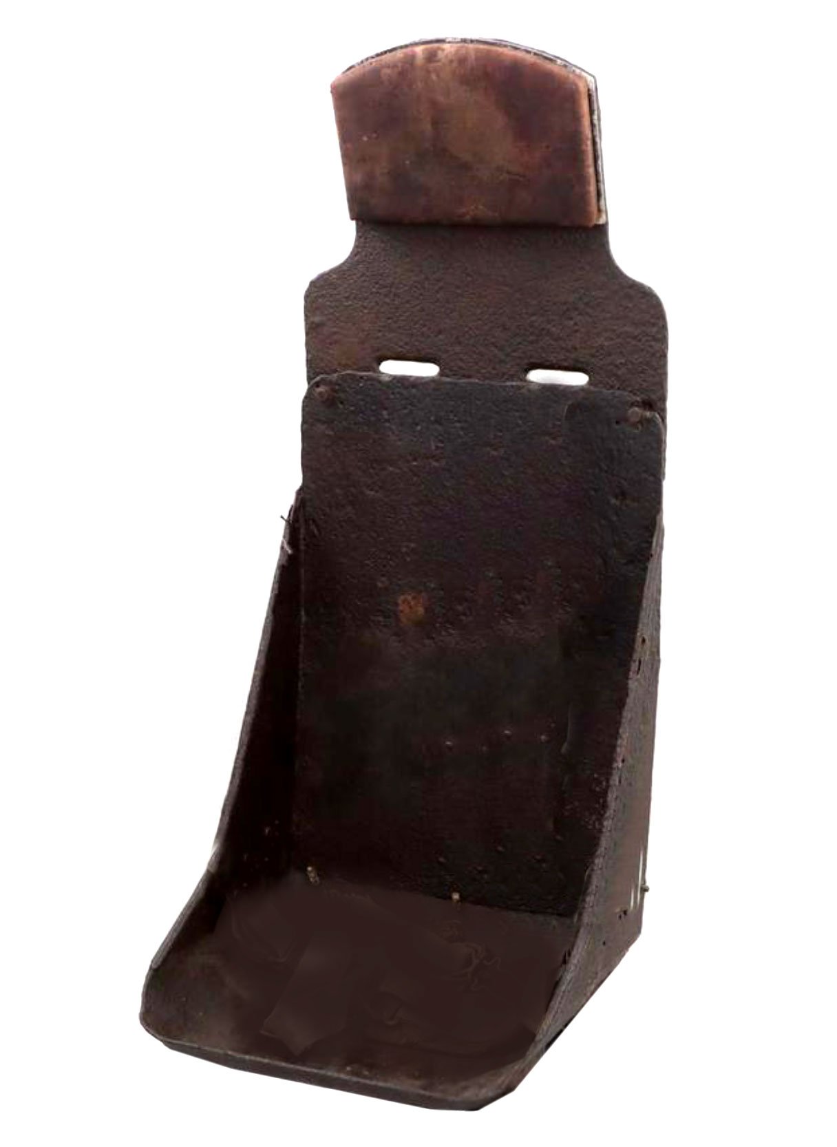
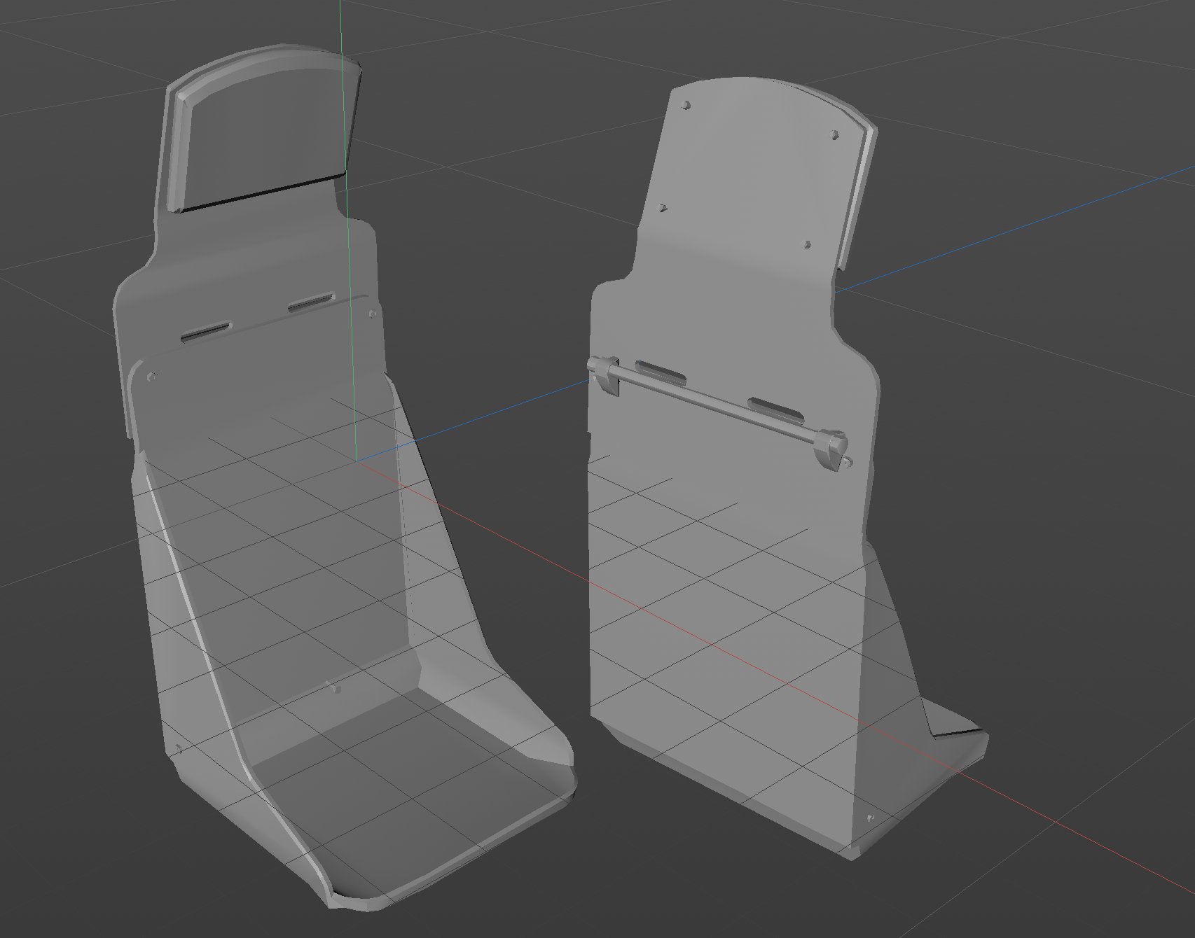
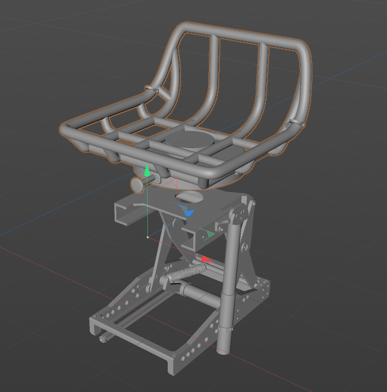
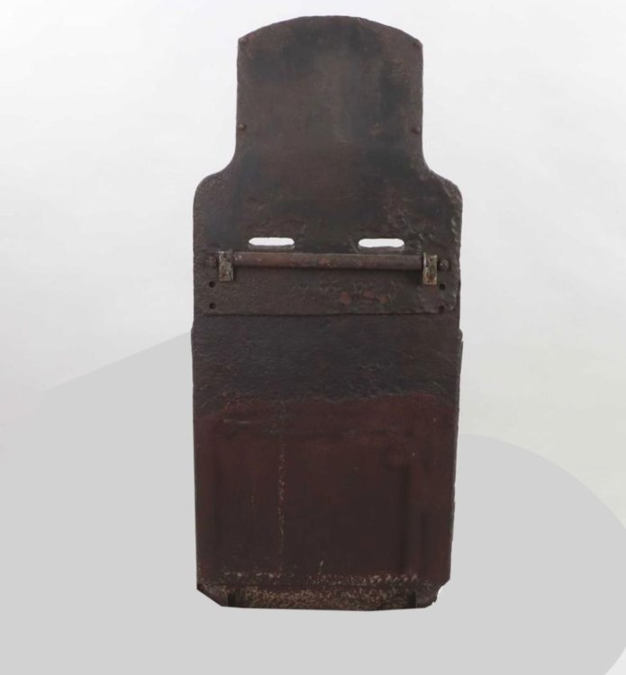
I was not happy with the seats. Not in the Aires set, Hasegawa nor Trumpeter. Just too thick. Undersized. and incorrect shape. I found some good images of a relic seat online, including measurements. Threw these in AI 3D software and tweaked a little.


-
1/32 Ju-87D Stuka
JeroenPeters replied to JeroenPeters's topic in LSM 1/35 and Larger Work In Progress
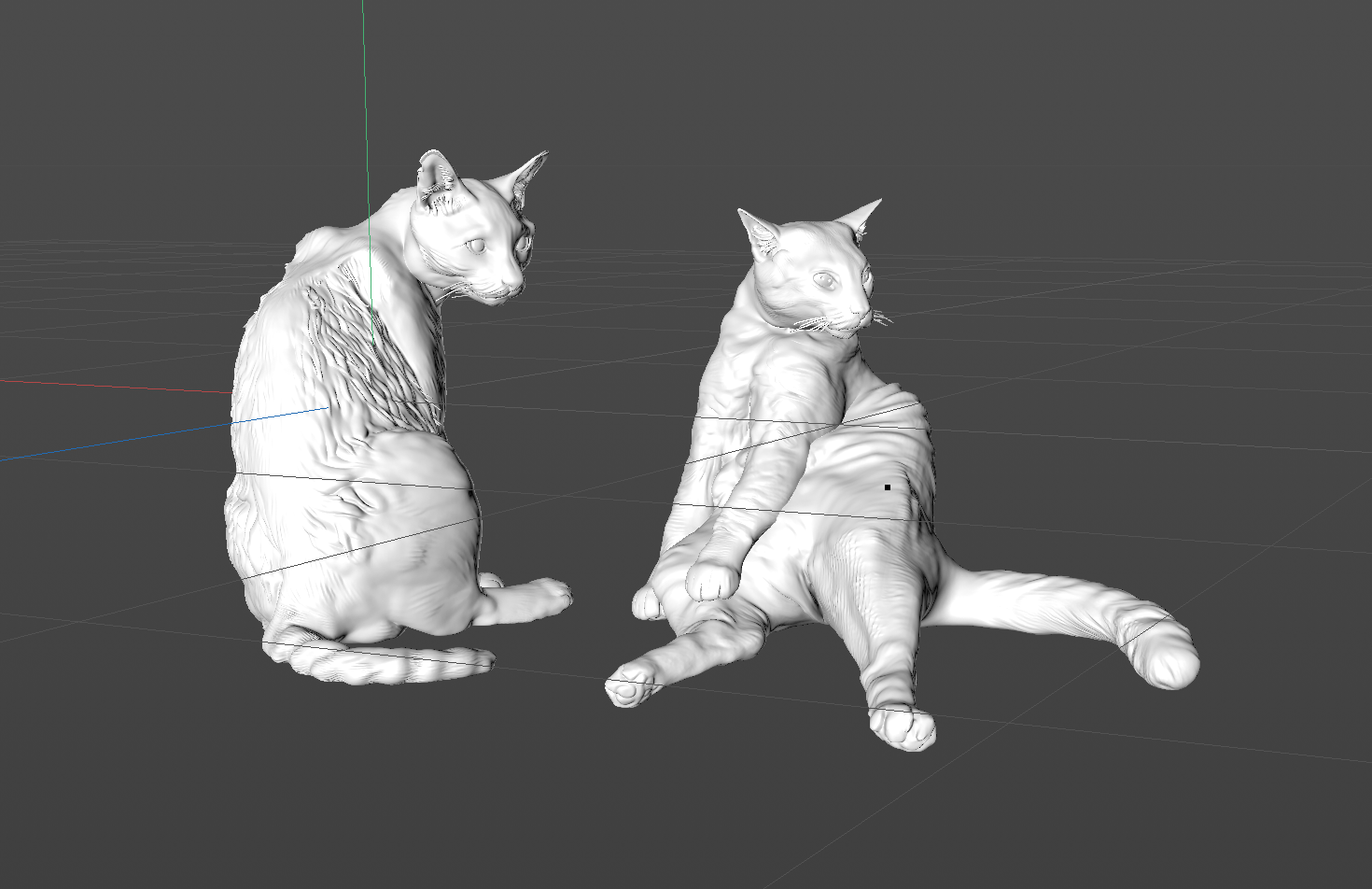
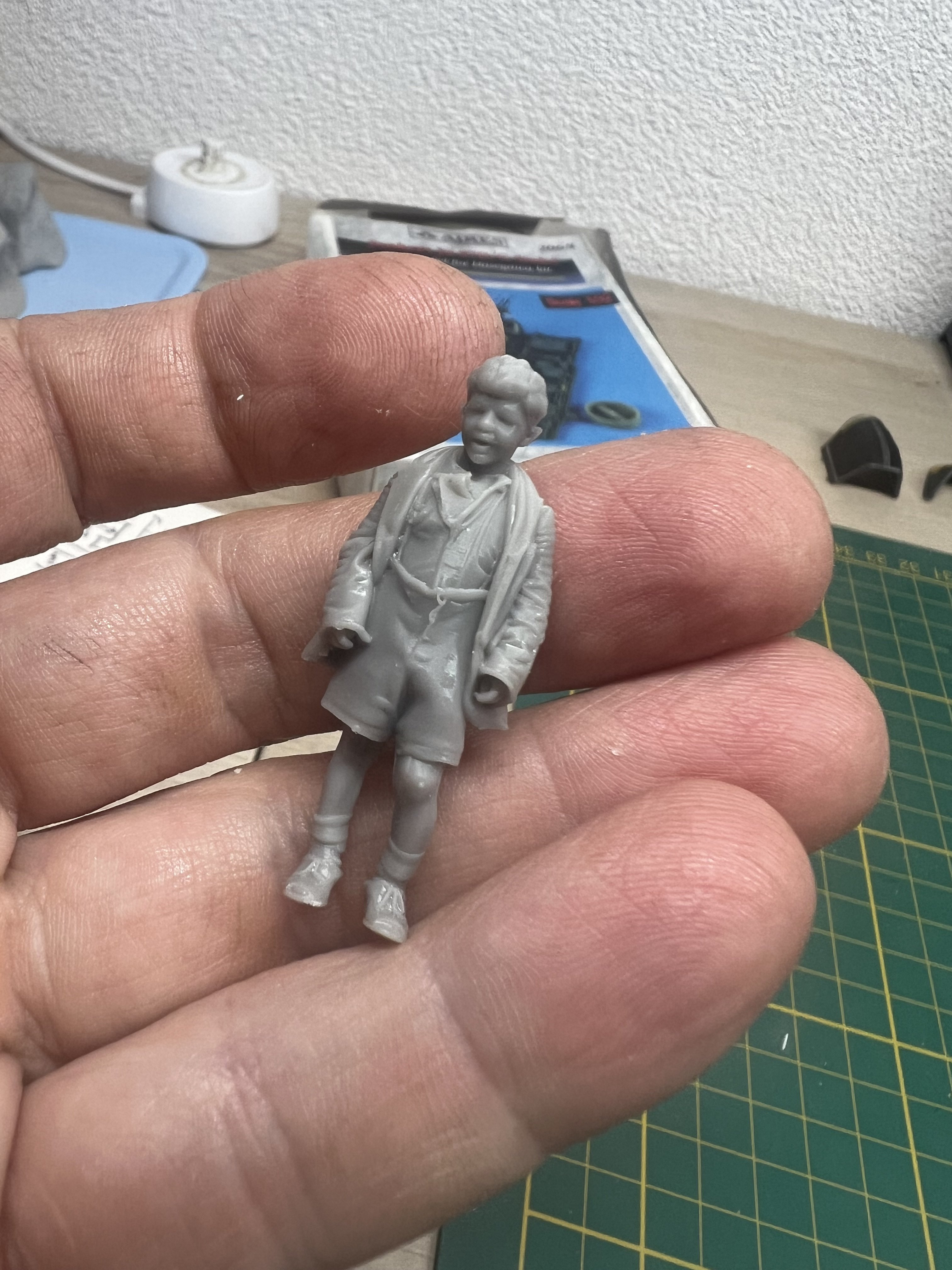
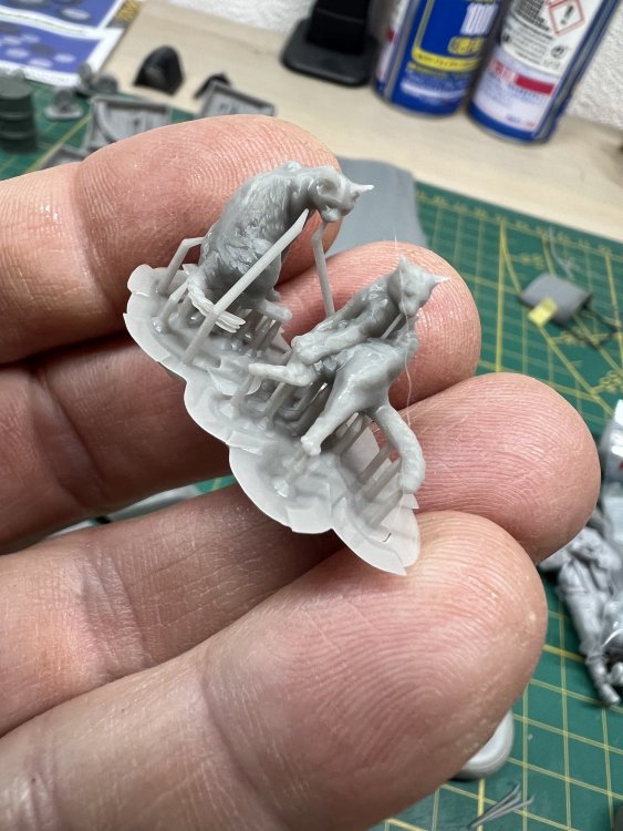
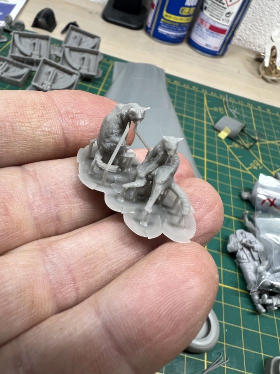
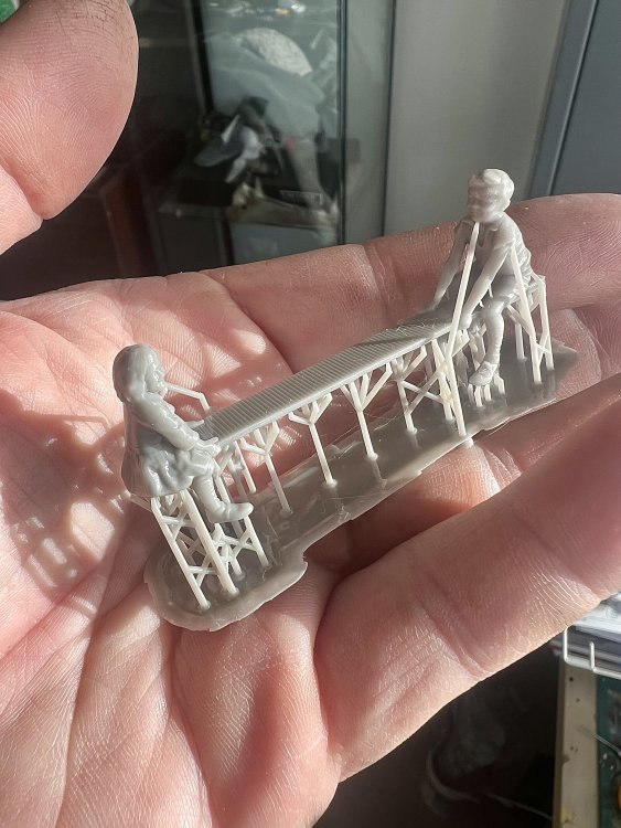
just for fun. Two stray cats looking at the playing kids. Took some 3D modelling to get them to my liking.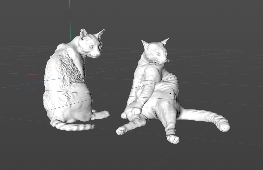
-
1/32 Ju-87D Stuka
JeroenPeters replied to JeroenPeters's topic in LSM 1/35 and Larger Work In Progress
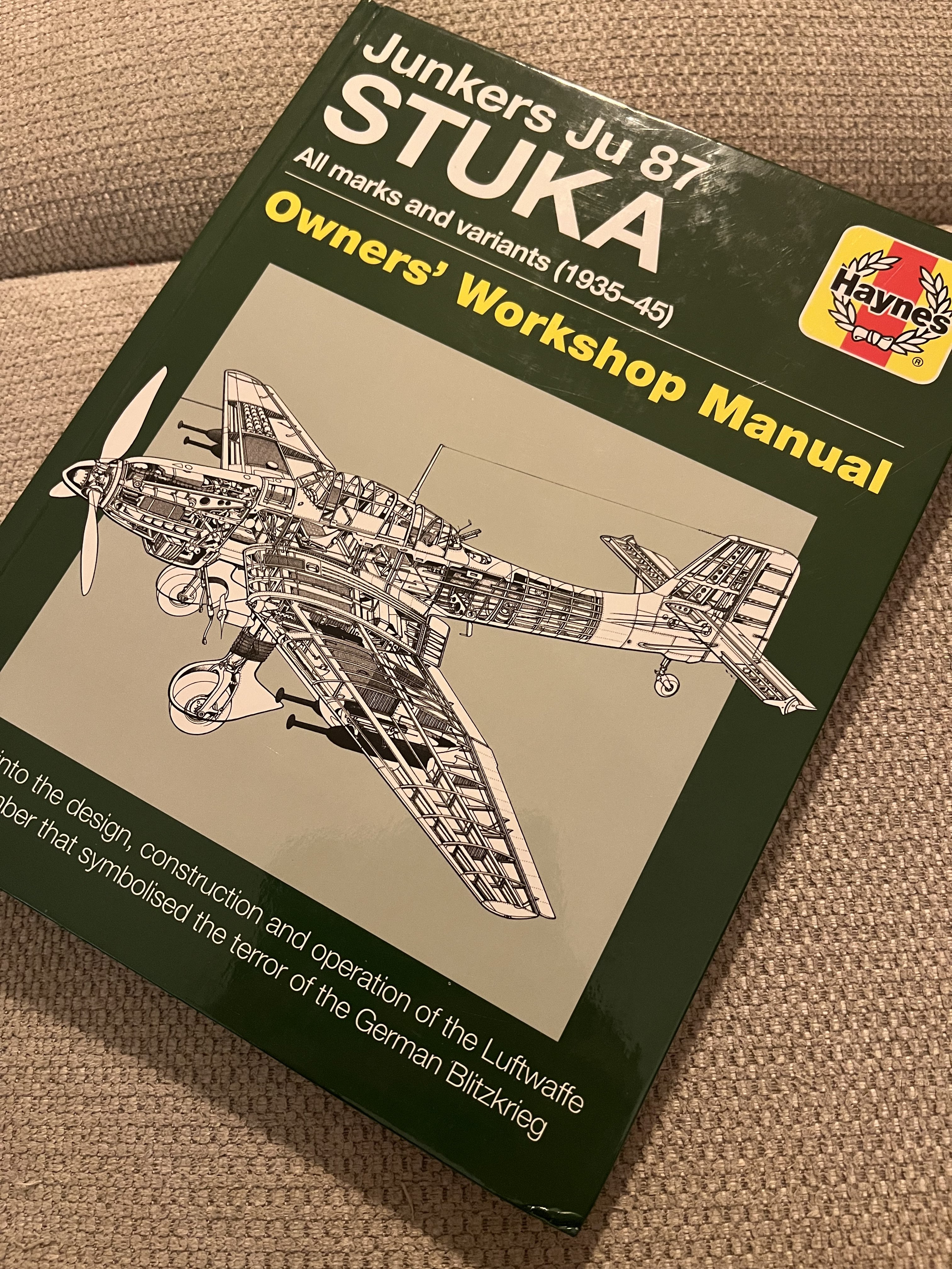
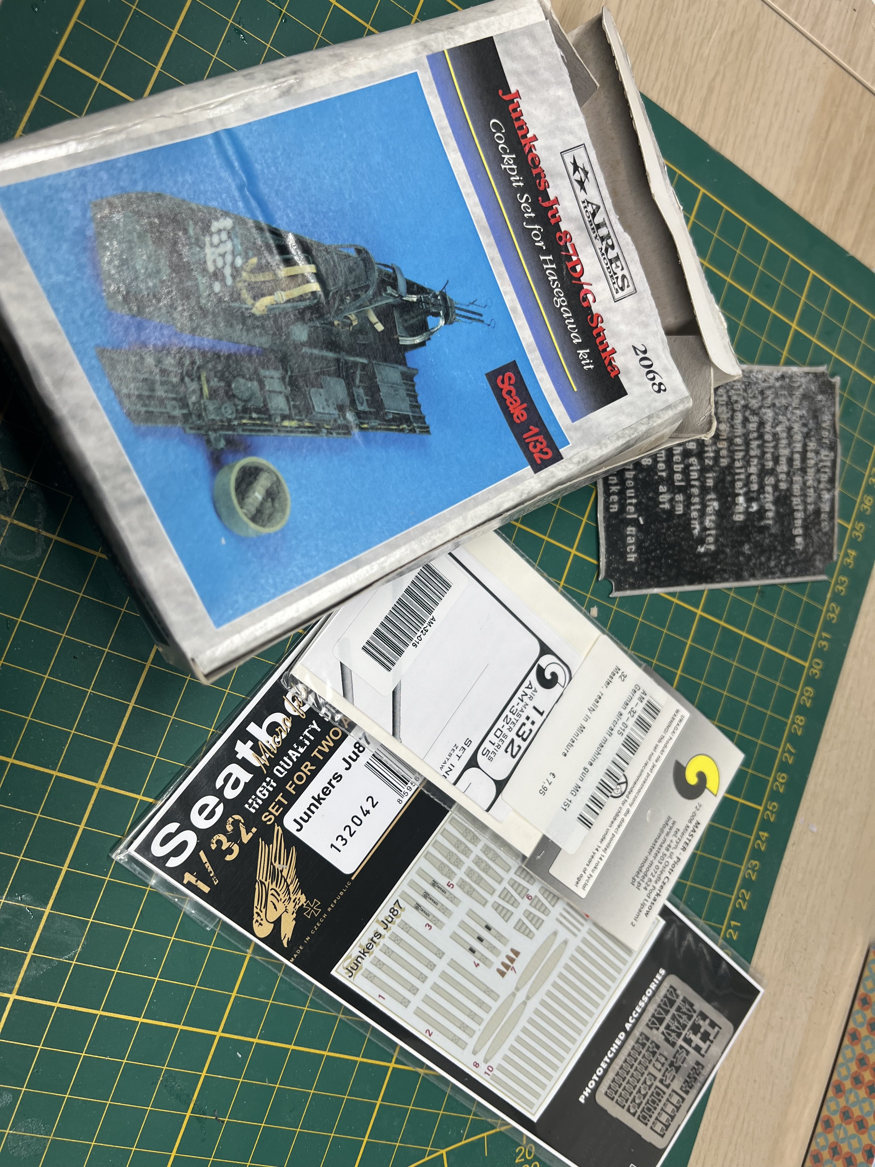
Since i have few to no knowledge on the Stuka at all, i have work to do. LSP member Antonio Argudo shared his dropbox with me (very useful) and I’m accumulating books. Just got this one in the mail. There is so much non standard on this plane, it feels like i’m really starting everything from scratch.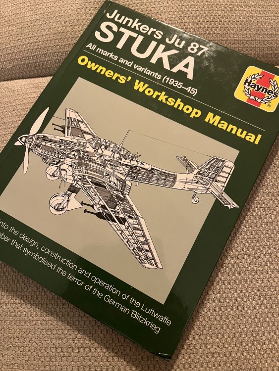
-
1/32 ME-262A-2a/U2
JeroenPeters replied to JeroenPeters's topic in LSM 1/35 and Larger Work In Progress
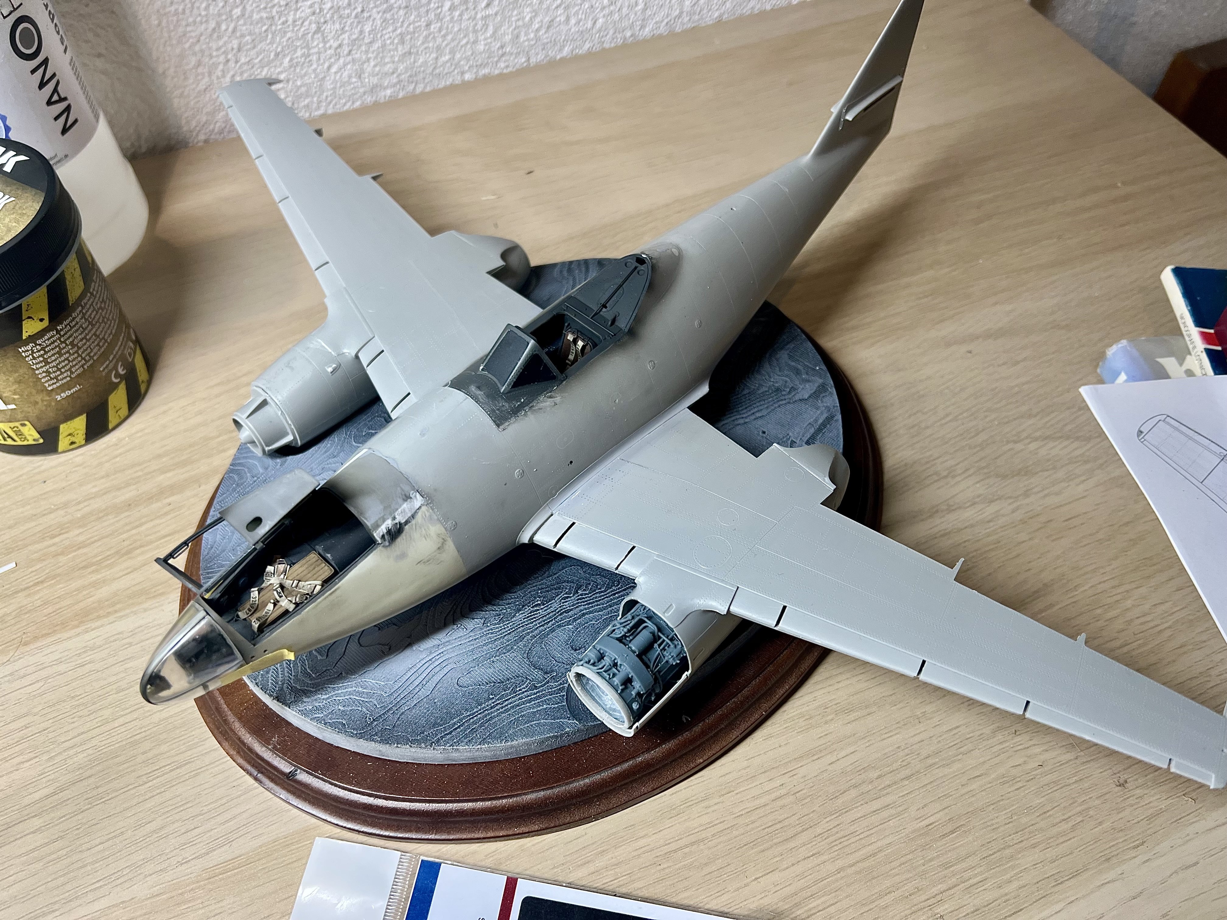
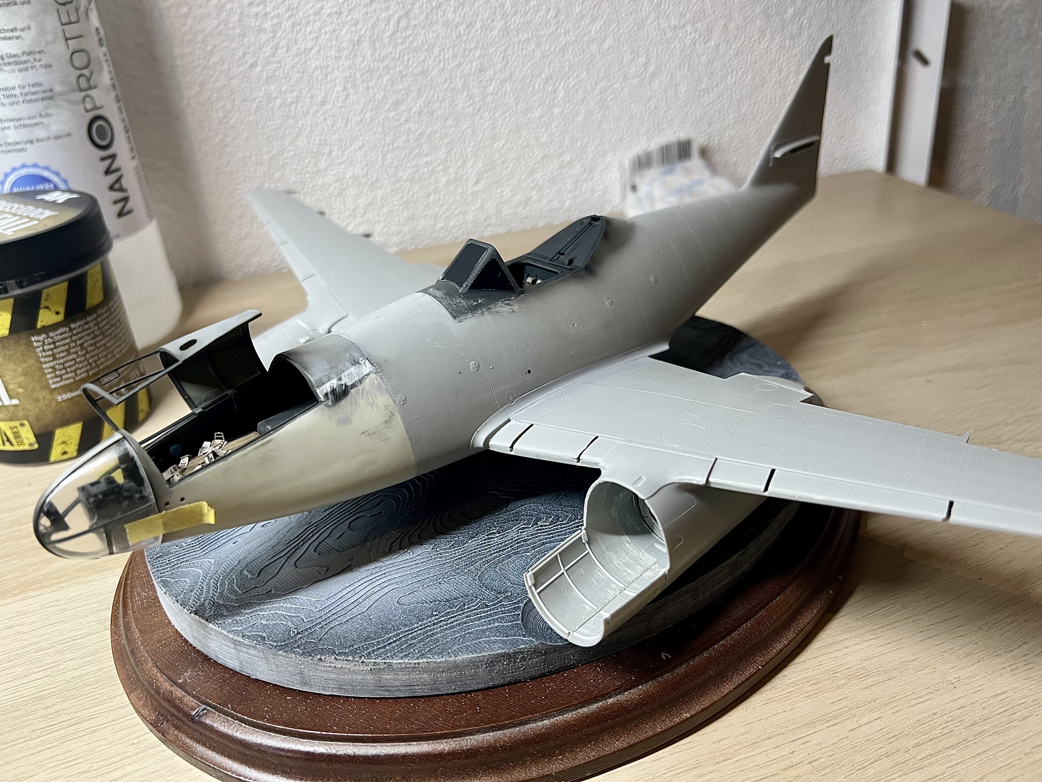
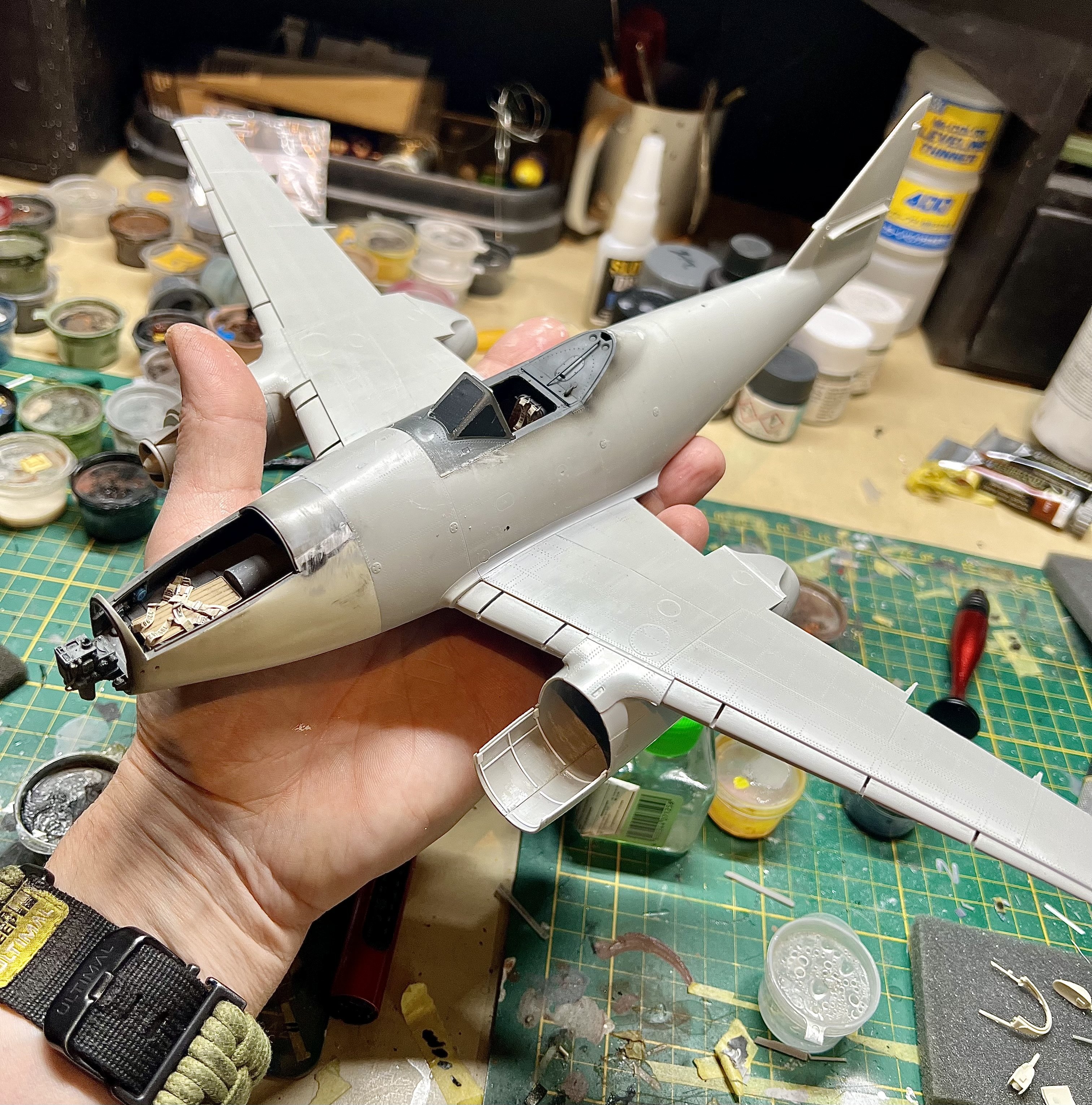
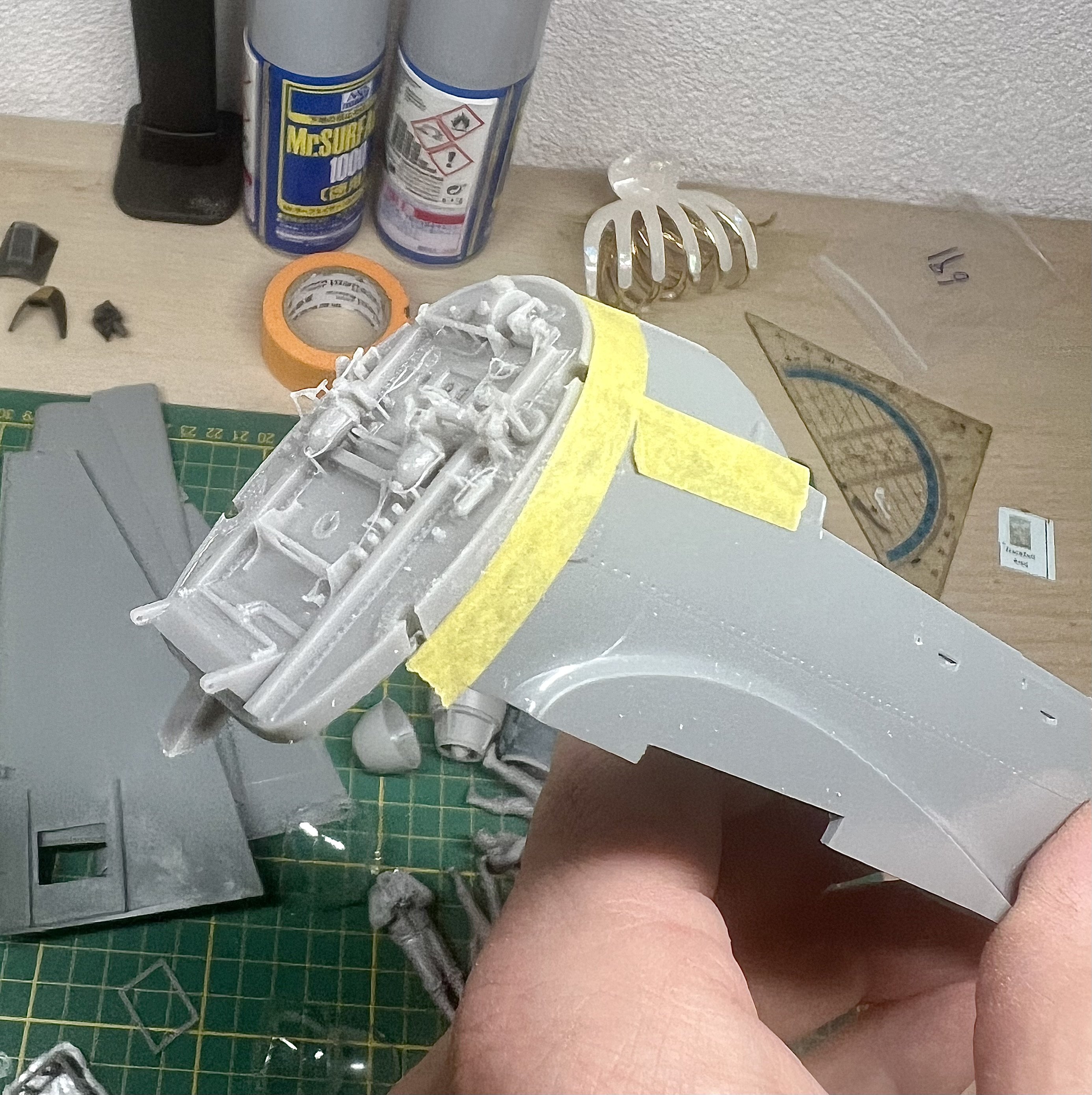
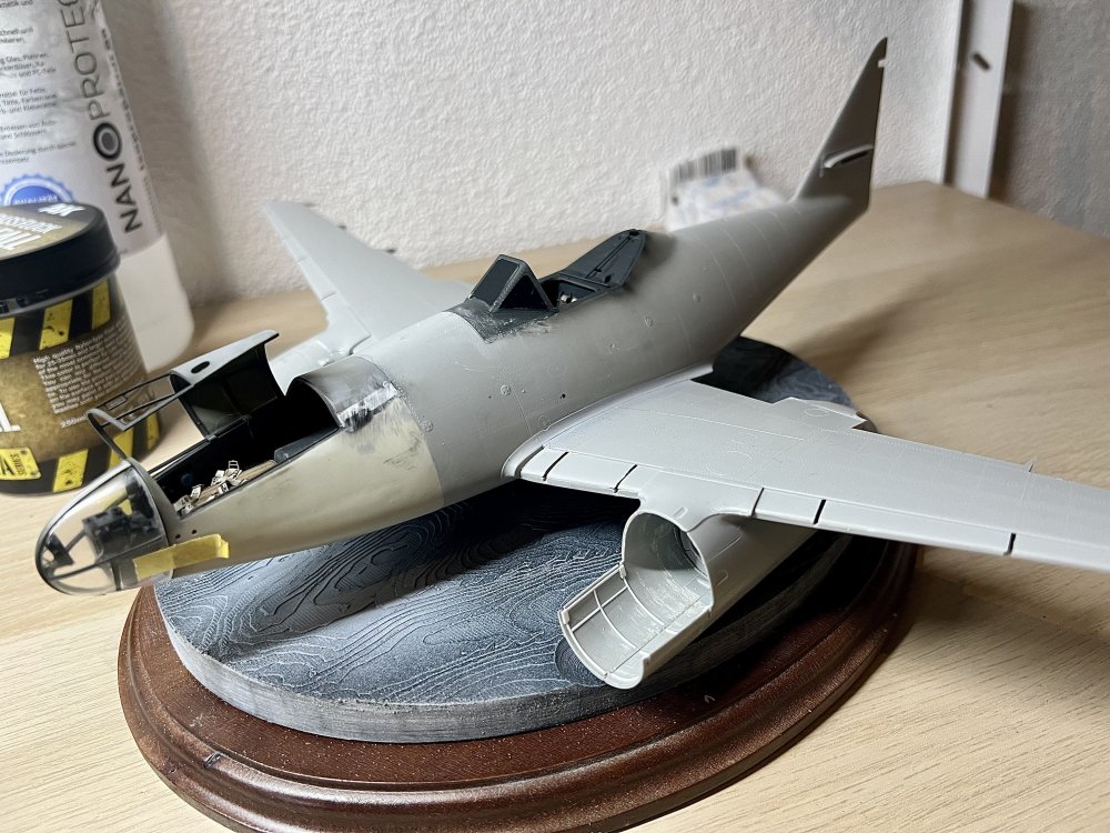
Cracked on with the nose. 3D printed Bombsight installed. Polished the nose glass one last time. It doesn’t get better than this.

-
1/32 Ju-87D Stuka
JeroenPeters replied to JeroenPeters's topic in LSM 1/35 and Larger Work In Progress
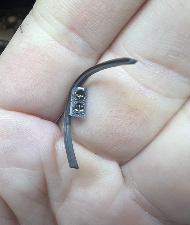
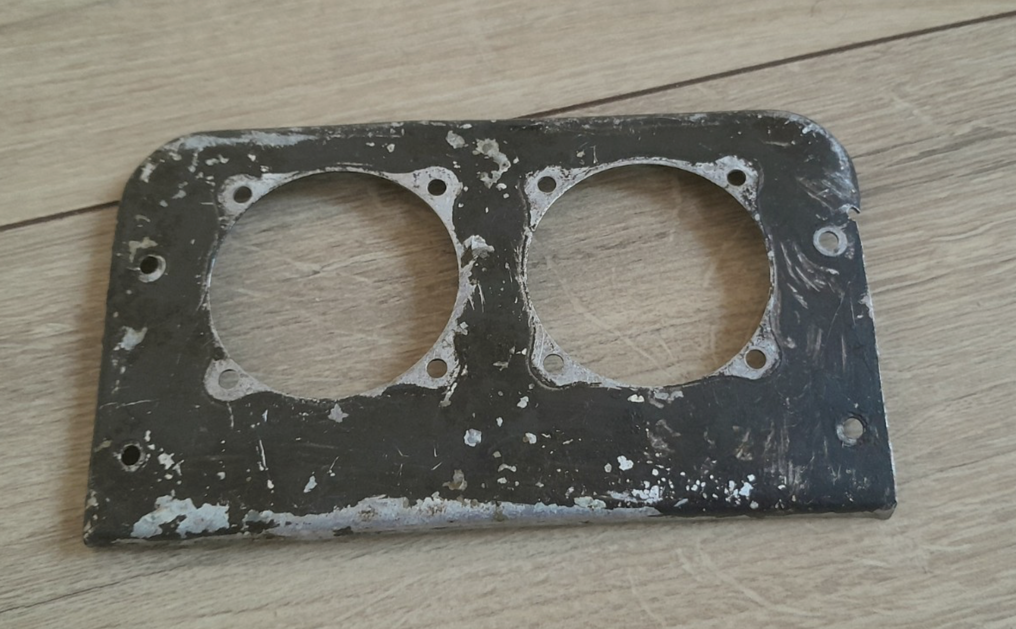
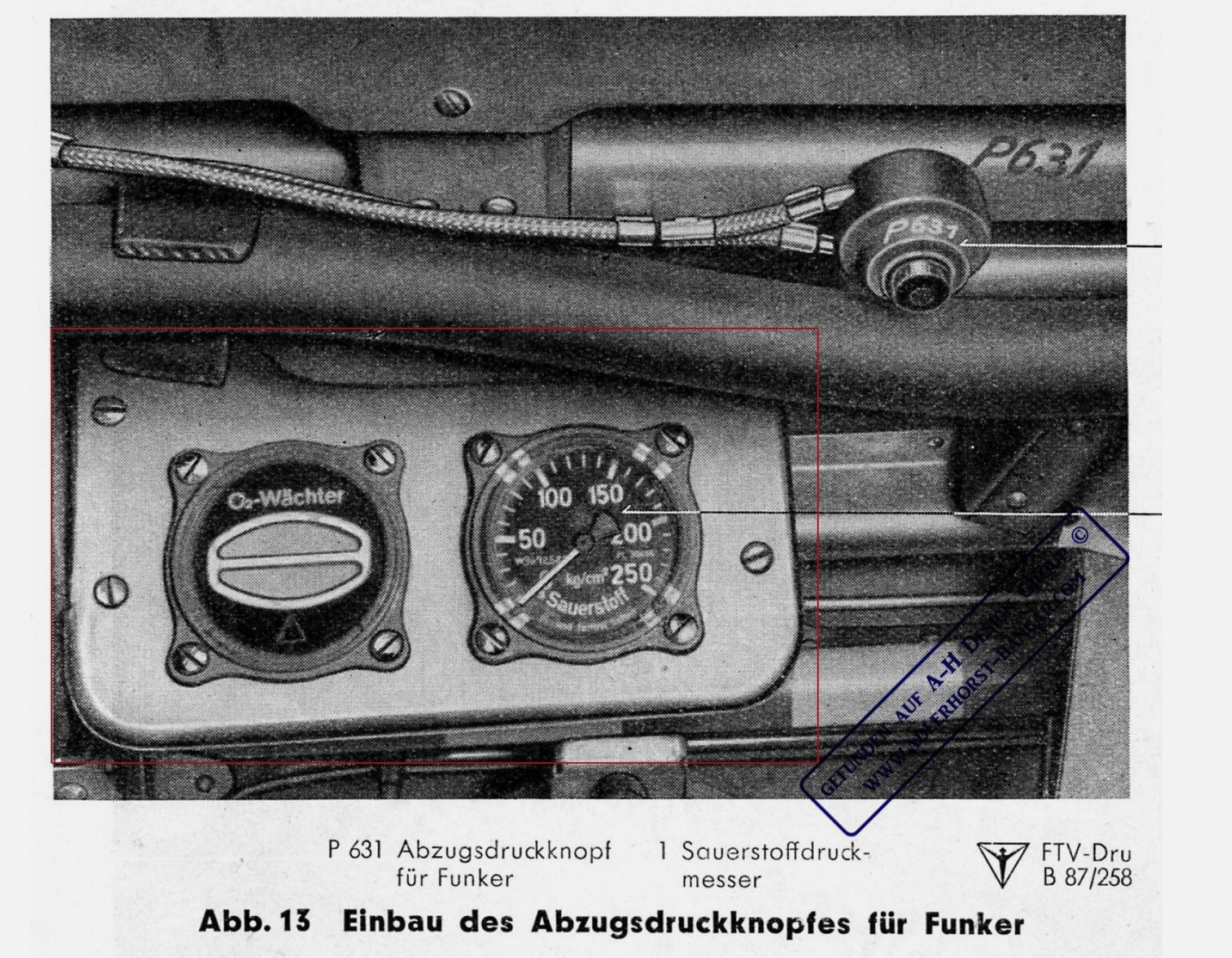
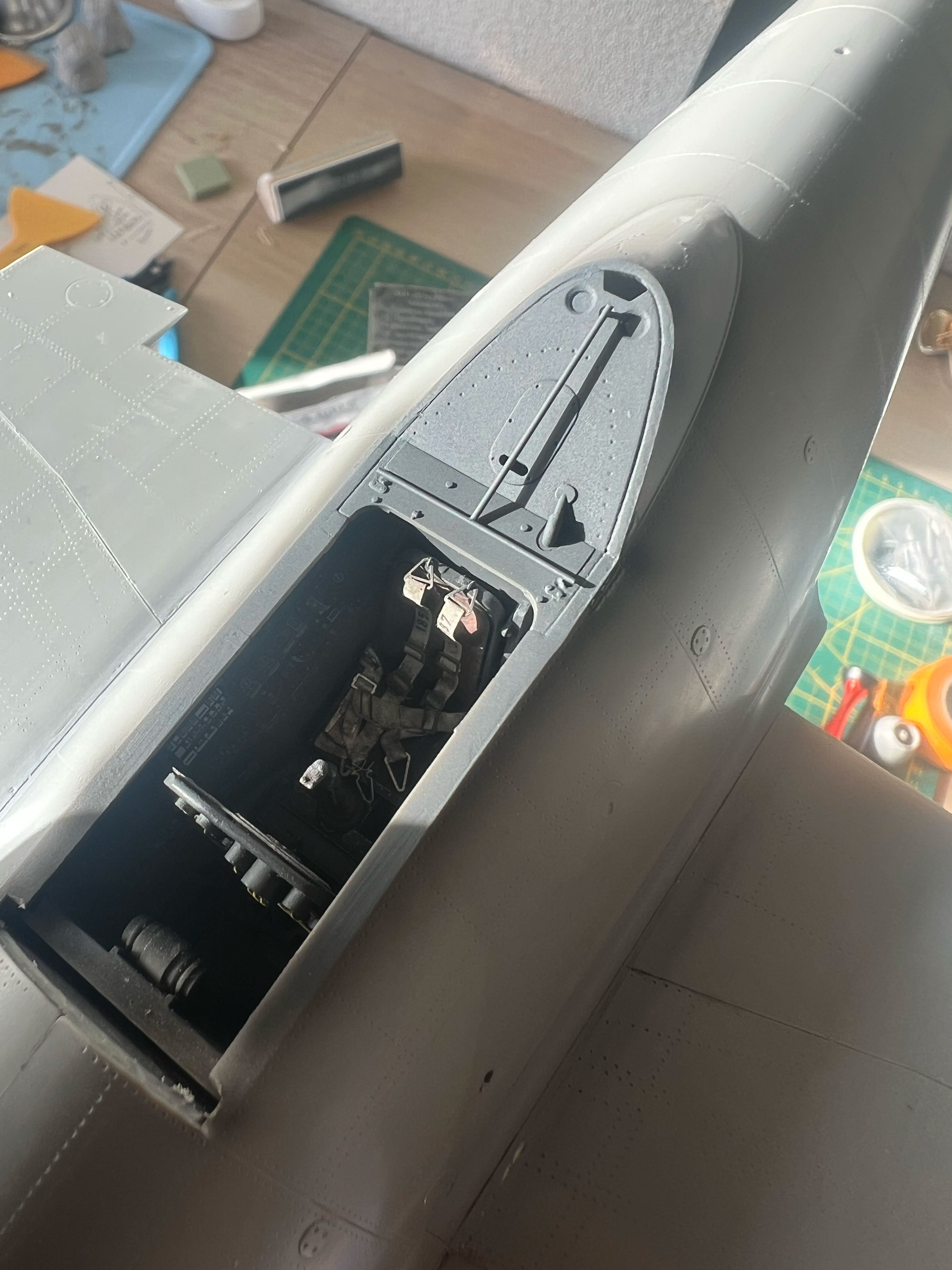
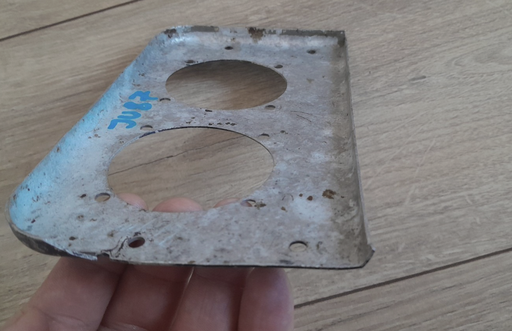
So... managed to score this oxygen instrument - panel from the left side of the cockpit wall. Still has most of its RLM66 paint. I might have both instruments in my stash. Need to check. This will go perfect with this build. Not sure on how I'll mount it, but I'll figure something out.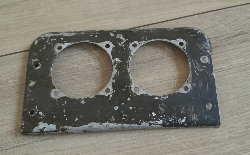
-
1/32 Ju-87D Stuka
JeroenPeters replied to JeroenPeters's topic in LSM 1/35 and Larger Work In Progress
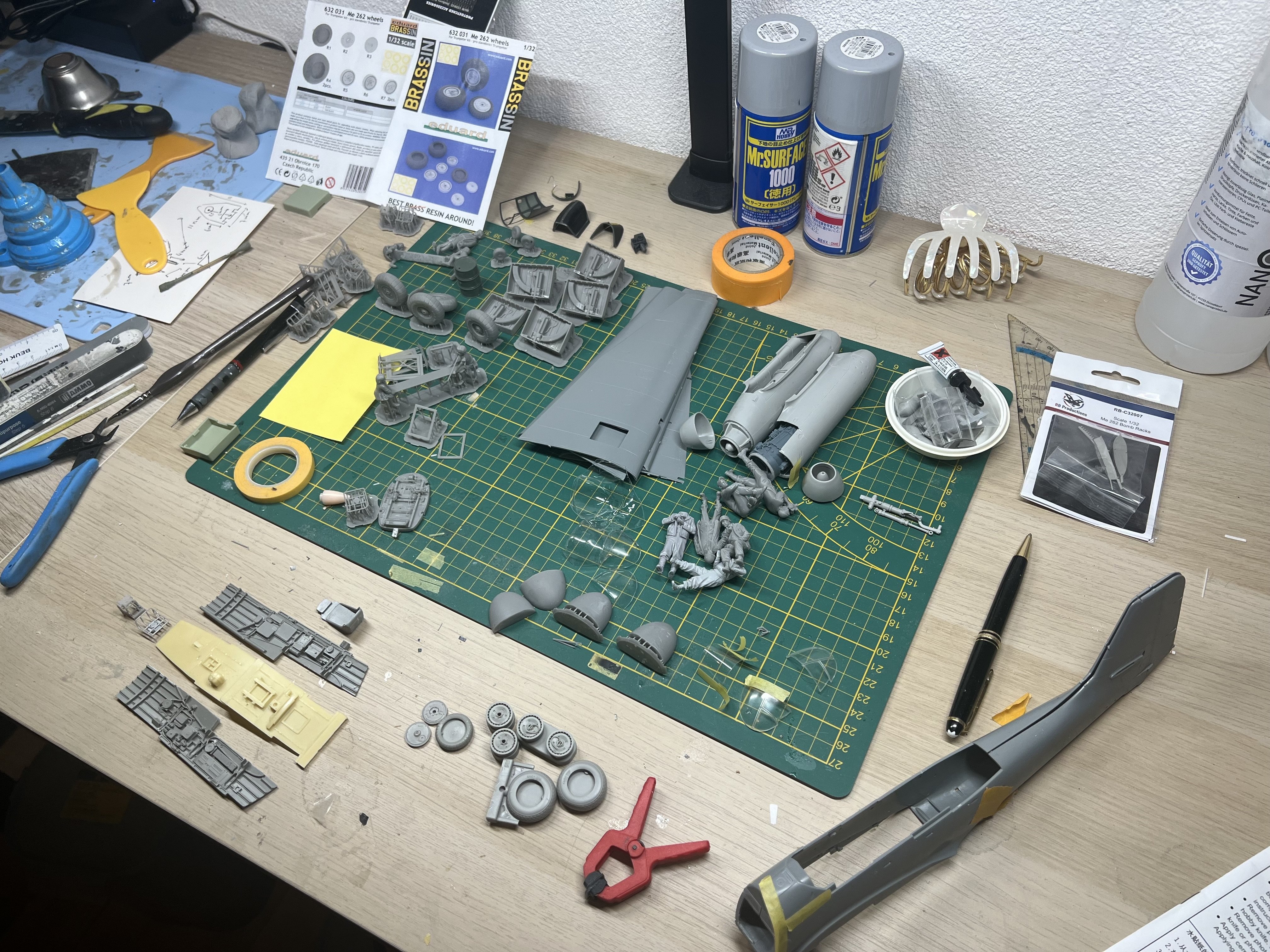
Started cutting resin on the Aires cockpit for the ju-87D. Warped like a banana. But nothing some boiling water won’t fix. With 2 stuka’s on the go and the 262, the bench will get worse.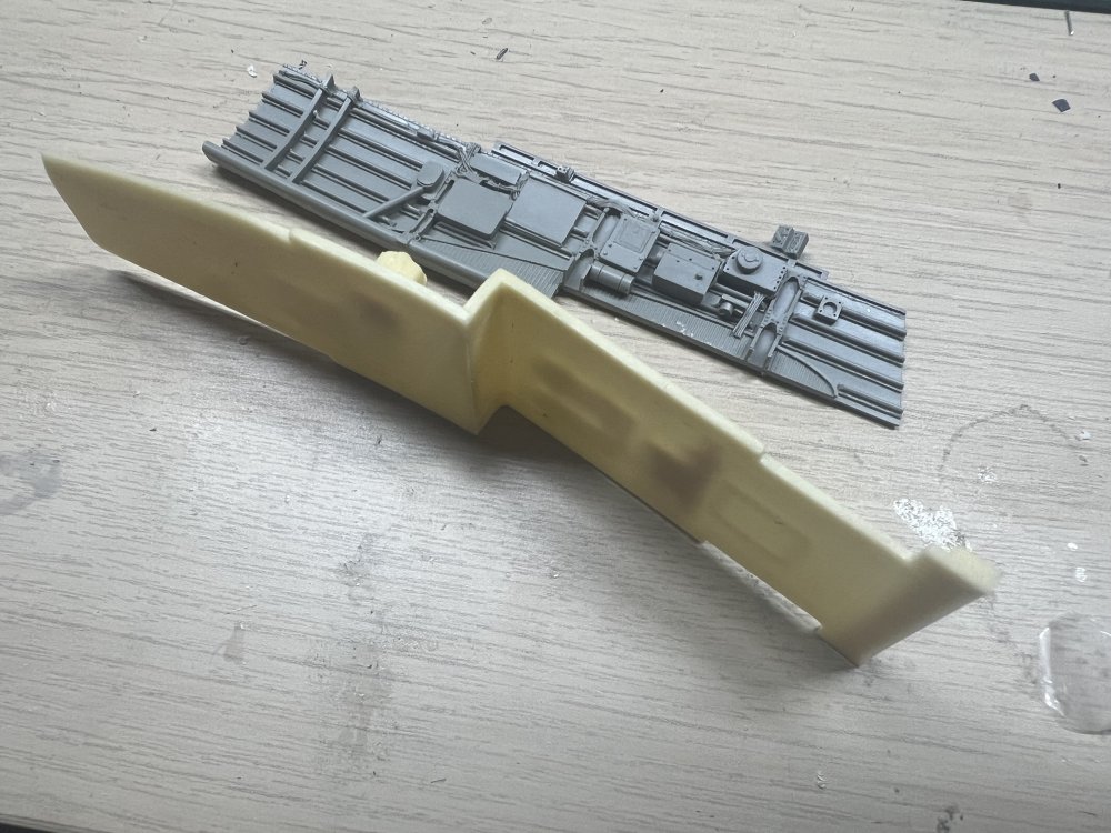

-
1/32 Ju-87D Stuka
JeroenPeters replied to JeroenPeters's topic in LSM 1/35 and Larger Work In Progress
Printed the wheels too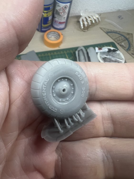
-
1/32 Ju-87D Stuka
JeroenPeters replied to JeroenPeters's topic in LSM 1/35 and Larger Work In Progress
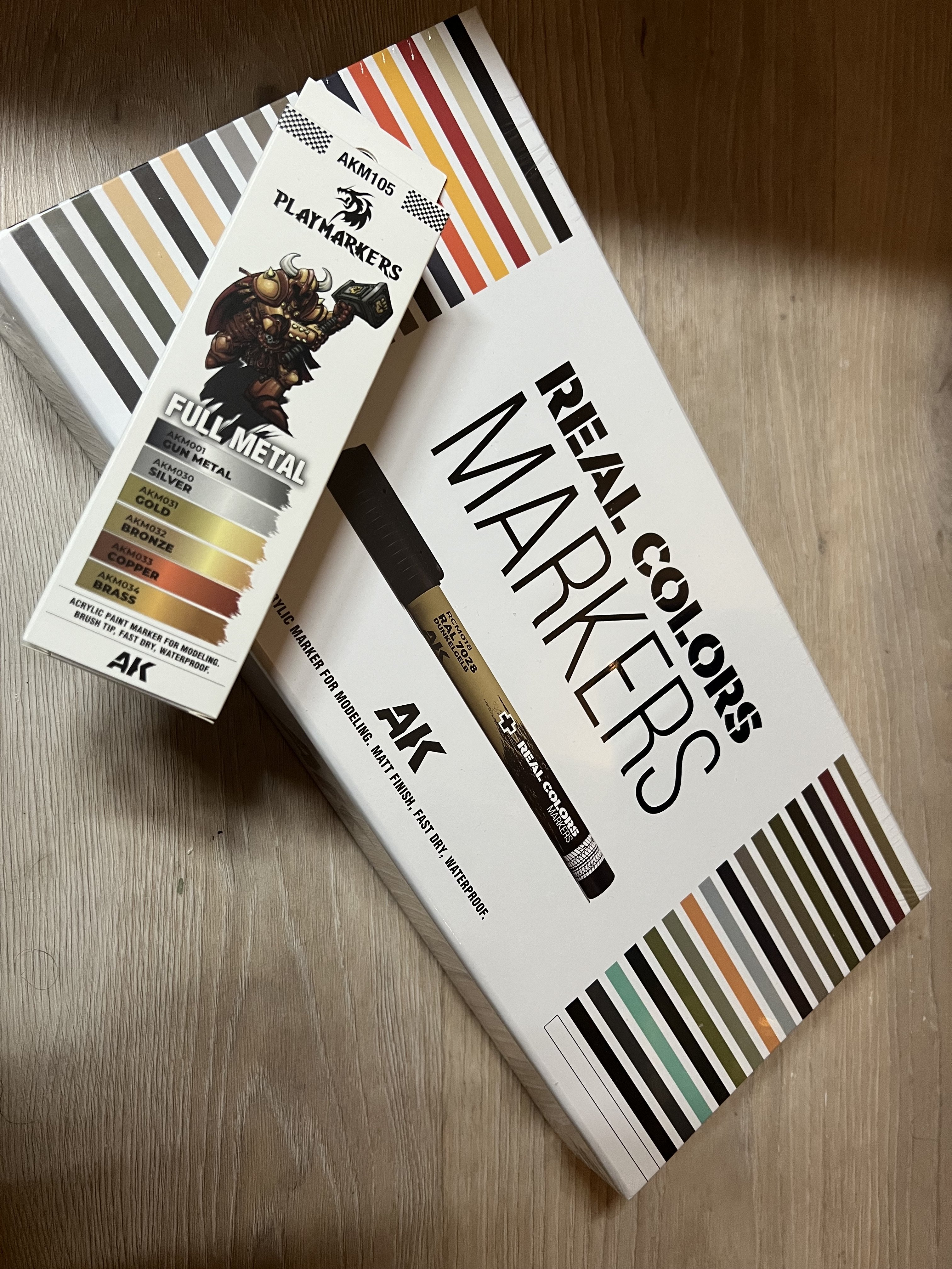
Just recieved these AK paint markers. Should be handy for details. And reprinted the engine at 98% size which makes fit the Hasegawa fuse better.

-
1/32 Ju-87D Stuka
JeroenPeters replied to JeroenPeters's topic in LSM 1/35 and Larger Work In Progress
Et voila. And another rascal for the playground.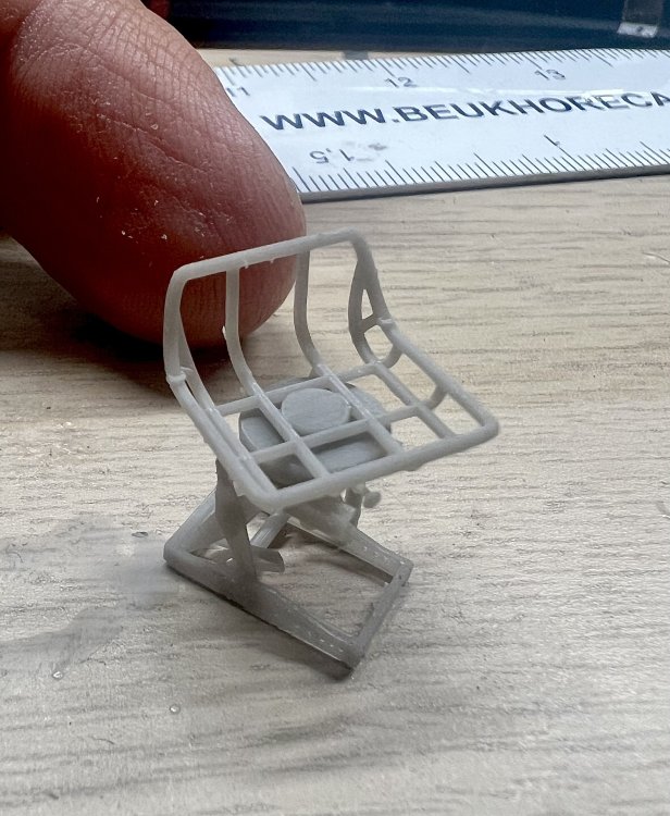

-
1/32 Ju-87D Stuka
JeroenPeters replied to JeroenPeters's topic in LSM 1/35 and Larger Work In Progress
Seat printed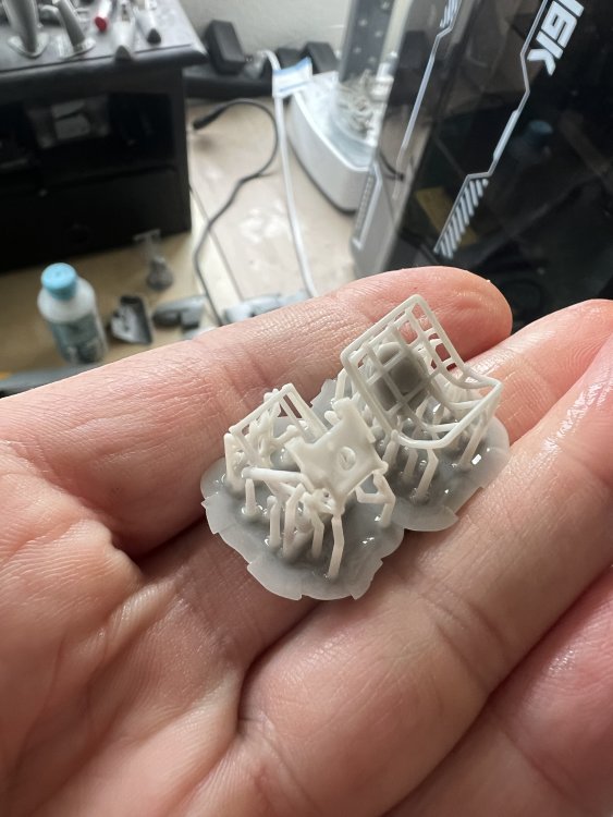

-
1/32 Ju-87D Stuka
JeroenPeters replied to JeroenPeters's topic in LSM 1/35 and Larger Work In Progress
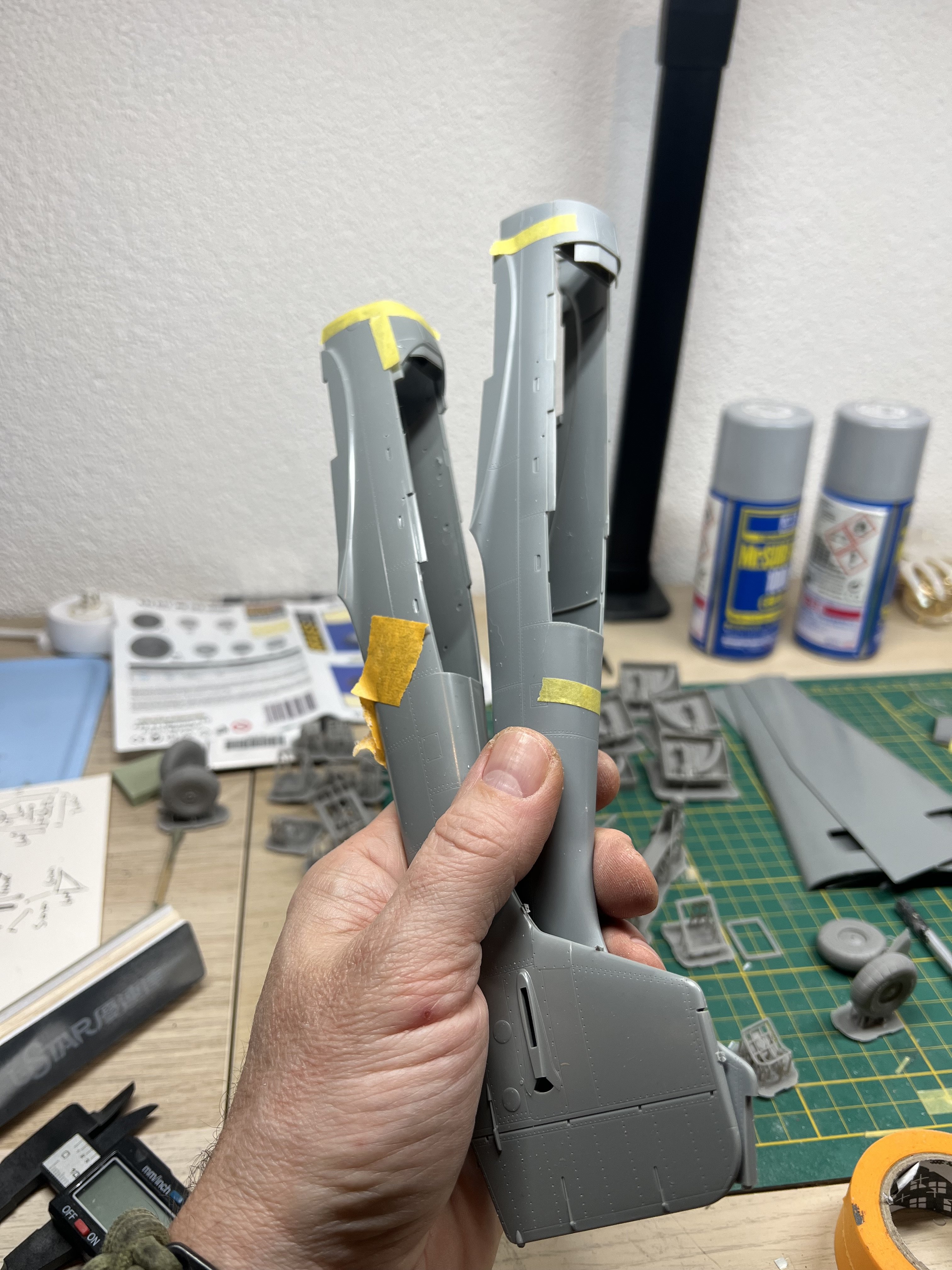
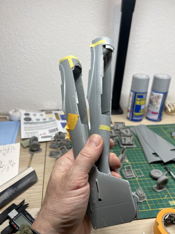
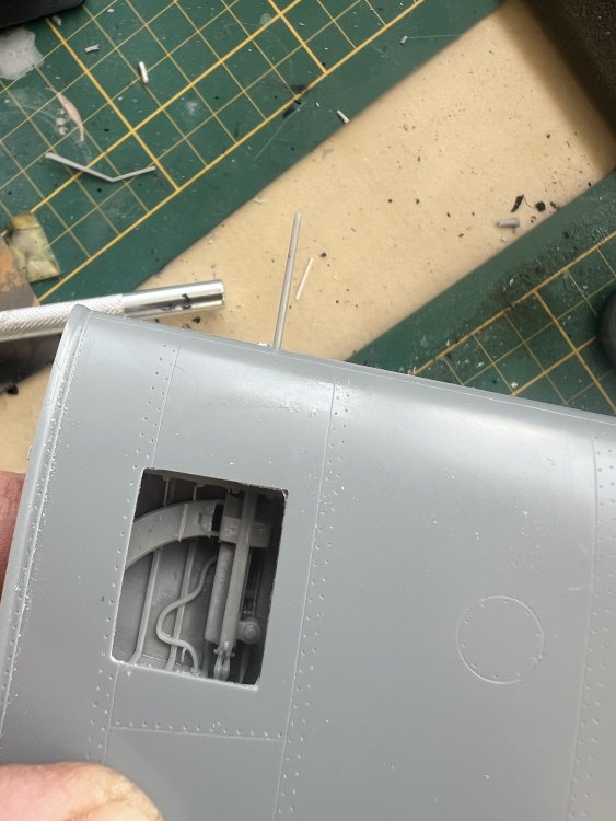
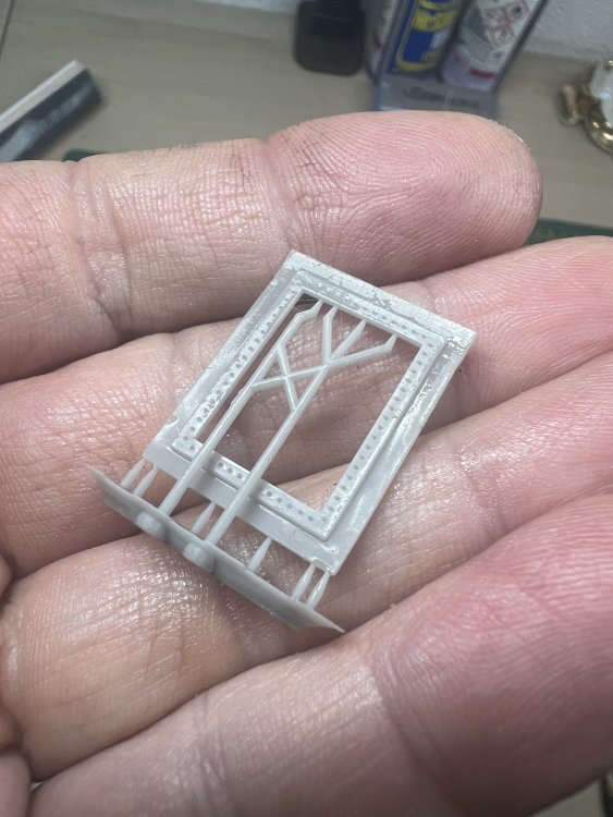
Almost a perfect fit for the inner hatch frame.
-
1/32 ME-262A-2a/U2
JeroenPeters replied to JeroenPeters's topic in LSM 1/35 and Larger Work In Progress
The T-bar at the rear cockpit deck came broken in the Sprue. Made a new one from thin rod and sprayed the lot.
-
1/32 Ju-87D Stuka
JeroenPeters replied to JeroenPeters's topic in LSM 1/35 and Larger Work In Progress
So I downloaded this gunners seat from Cults3D (I believe). It came with harness and it took me an entire evening to remove it in my 3D software.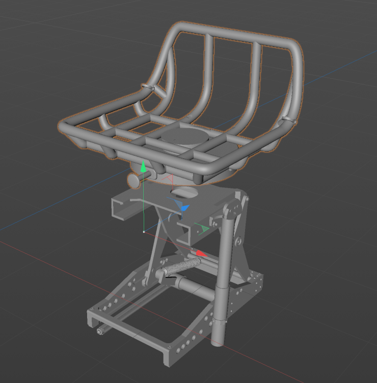
-
1/32 Ju-87D Stuka
JeroenPeters replied to JeroenPeters's topic in LSM 1/35 and Larger Work In Progress
Letting the prints properly cure, but had to do a quick dryfit. Also reprinted the entire engine after i mirrored it.
-
1/32 Ju-87D Stuka
JeroenPeters replied to JeroenPeters's topic in LSM 1/35 and Larger Work In Progress
More.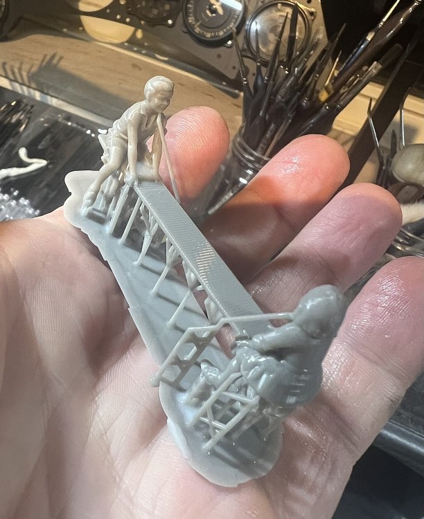
-
1/32 ME-262A-2a/U2
JeroenPeters replied to JeroenPeters's topic in LSM 1/35 and Larger Work In Progress
Small satisfying steps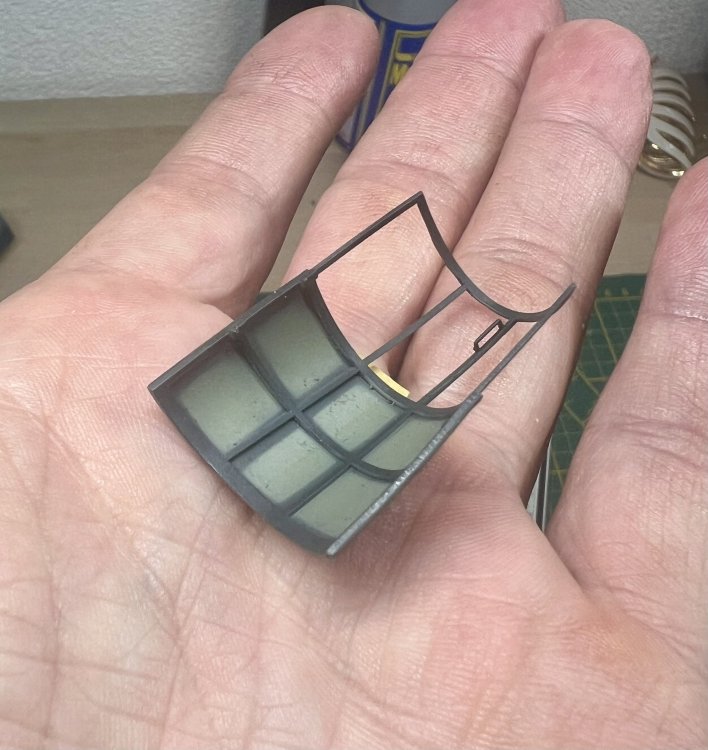
-
1/32 Ju-87D Stuka
JeroenPeters replied to JeroenPeters's topic in LSM 1/35 and Larger Work In Progress
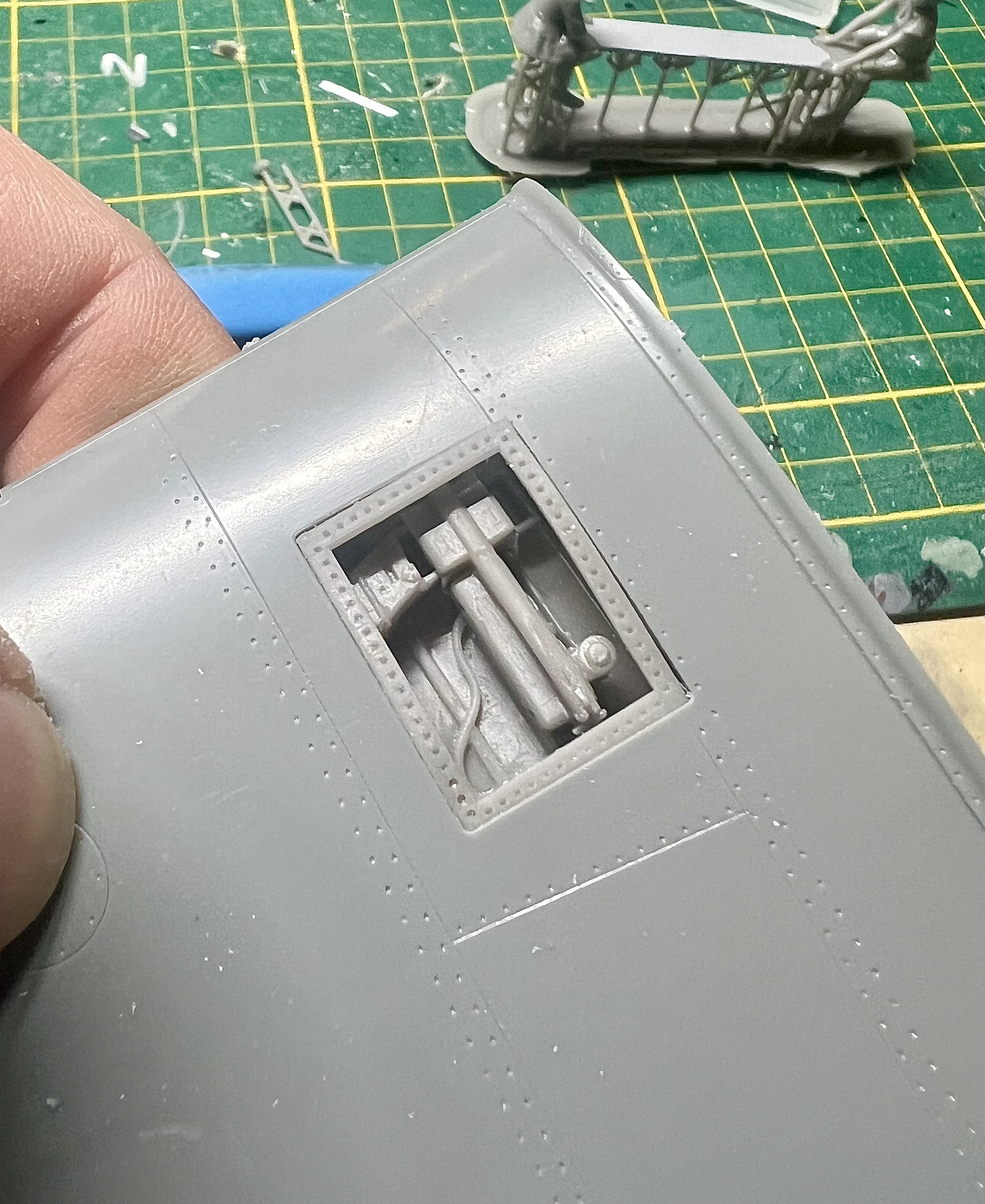
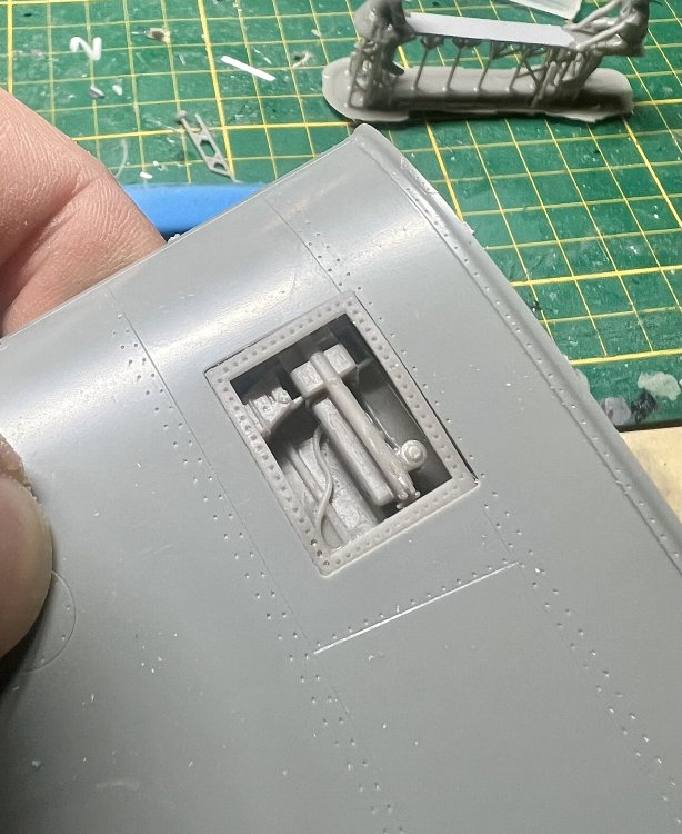
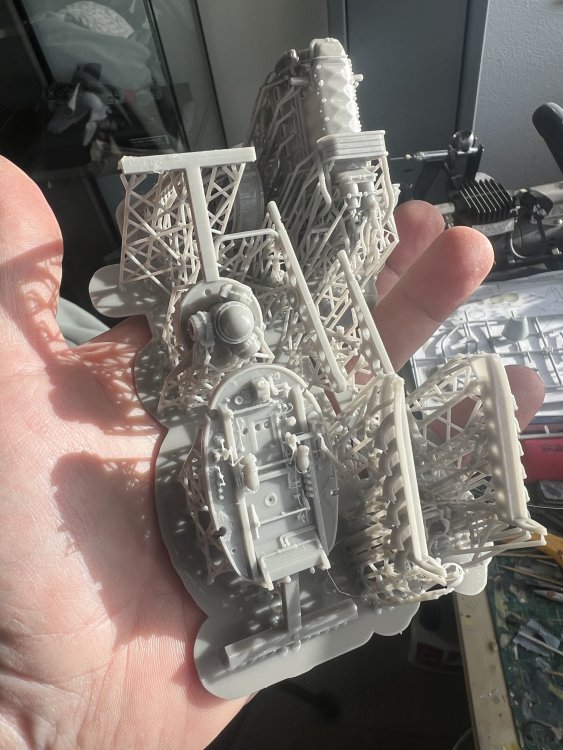
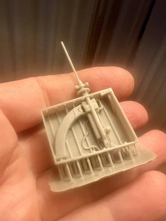
Goodies! Benefits of living 10 min from the aviation megastore. First print of the gunbay looks promising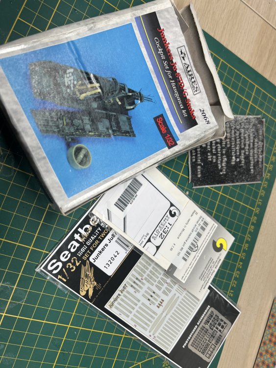
-
1/32 Ju-87D Stuka
JeroenPeters replied to JeroenPeters's topic in LSM 1/35 and Larger Work In Progress
Roughing it out and trying out numerous photo's of ww2 children on a seesaw. These two kids will be playing in front of the 2 Stuka's.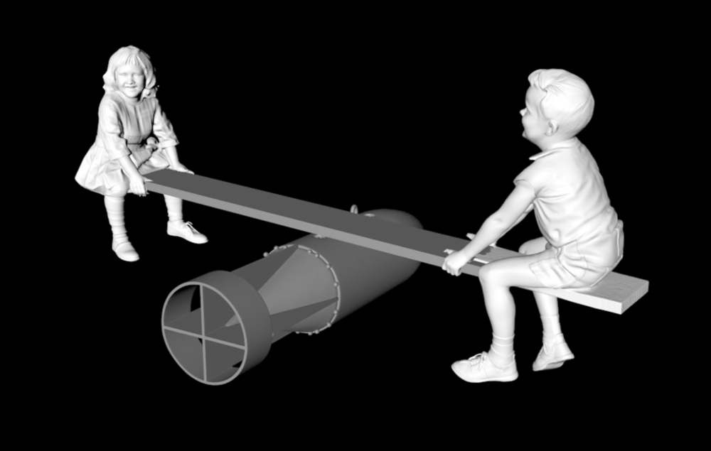
-
1/32 Ju-87D Stuka
JeroenPeters replied to JeroenPeters's topic in LSM 1/35 and Larger Work In Progress
What i only noticed yesterday is that the engine i printed was mirrored. Why? No clue. I’ll print a new one this weekend… -
1/32 ME-262A-2a/U2
JeroenPeters replied to JeroenPeters's topic in LSM 1/35 and Larger Work In Progress
The bombsight is coming along and spent some time in the spares box looking for some instruments inside the glass nose to replace the messed up ones from MDC. These coming from an Eduard bf108 panel i had left.