
JeroenPeters
-
Posts
4,904 -
Joined
-
Last visited
Content Type
Profiles
Forums
Events
Gallery
Everything posted by JeroenPeters
-

1/32 Ju-87D Stuka
JeroenPeters replied to JeroenPeters's topic in LSM 1/35 and Larger Work In Progress
Axing out the swastika’s looks like a good idea. Great pic! -
1/32 Ju-87D Stuka
JeroenPeters replied to JeroenPeters's topic in LSM 1/35 and Larger Work In Progress
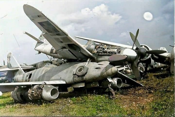
Yes. This ju-87g just landed and will be placed on top of the ju-87d in a scrapyard setting. Both in colours of Hans Rudel’s crare, who flew both the D and the G
-
1/32 Ju-87D Stuka
JeroenPeters replied to JeroenPeters's topic in LSM 1/35 and Larger Work In Progress
Some progress on the MG151 gunbays. I made the wing frame so, that it will slot in the hole and I don't have to thin the plastic around the edges too much.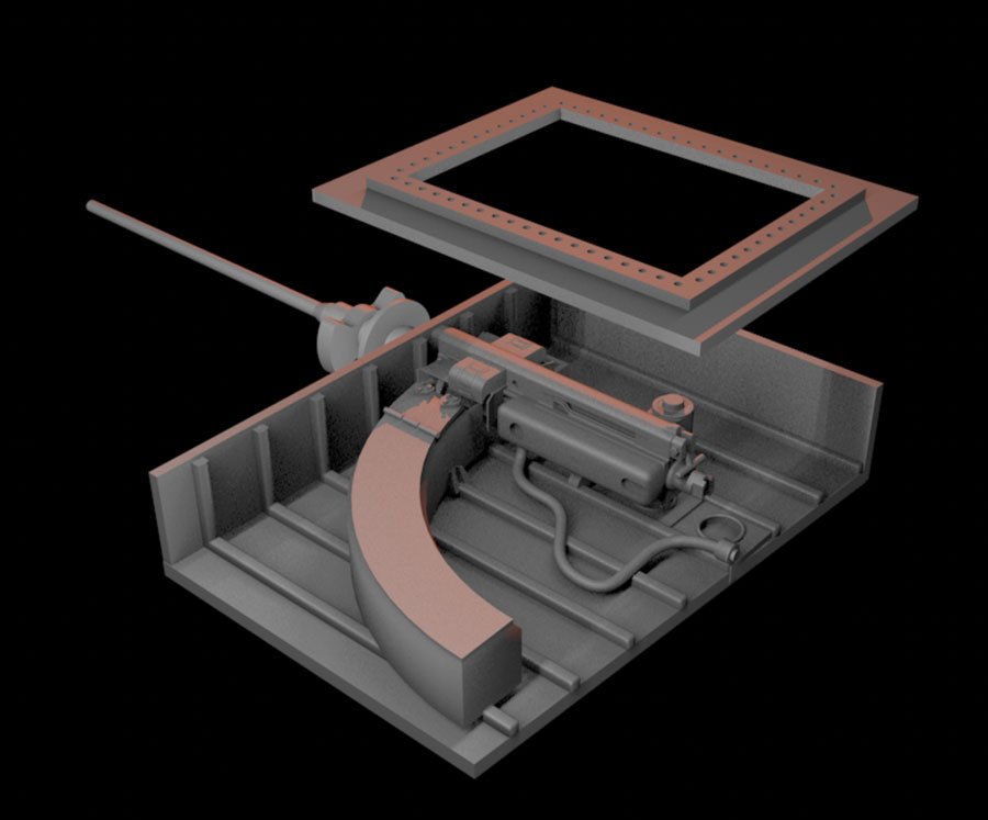
-
1/32 Ju-87D Stuka
JeroenPeters replied to JeroenPeters's topic in LSM 1/35 and Larger Work In Progress
I might add some boys to the diorama. Not sure about their interaction and stance, but the first Ai trial looks promising.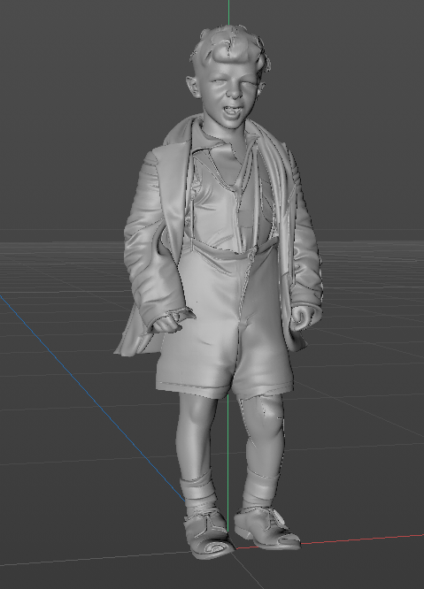
-
1/32 ME-262A-2a/U2
JeroenPeters replied to JeroenPeters's topic in LSM 1/35 and Larger Work In Progress
Perfect fit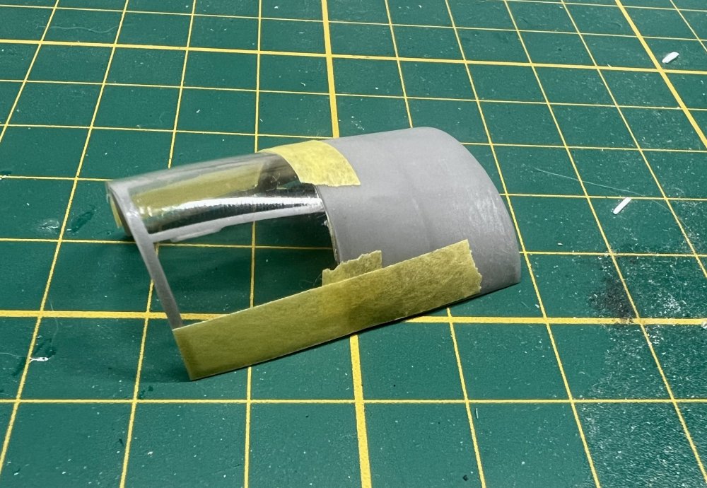
-
1/32 Ju-87D Stuka
JeroenPeters replied to JeroenPeters's topic in LSM 1/35 and Larger Work In Progress
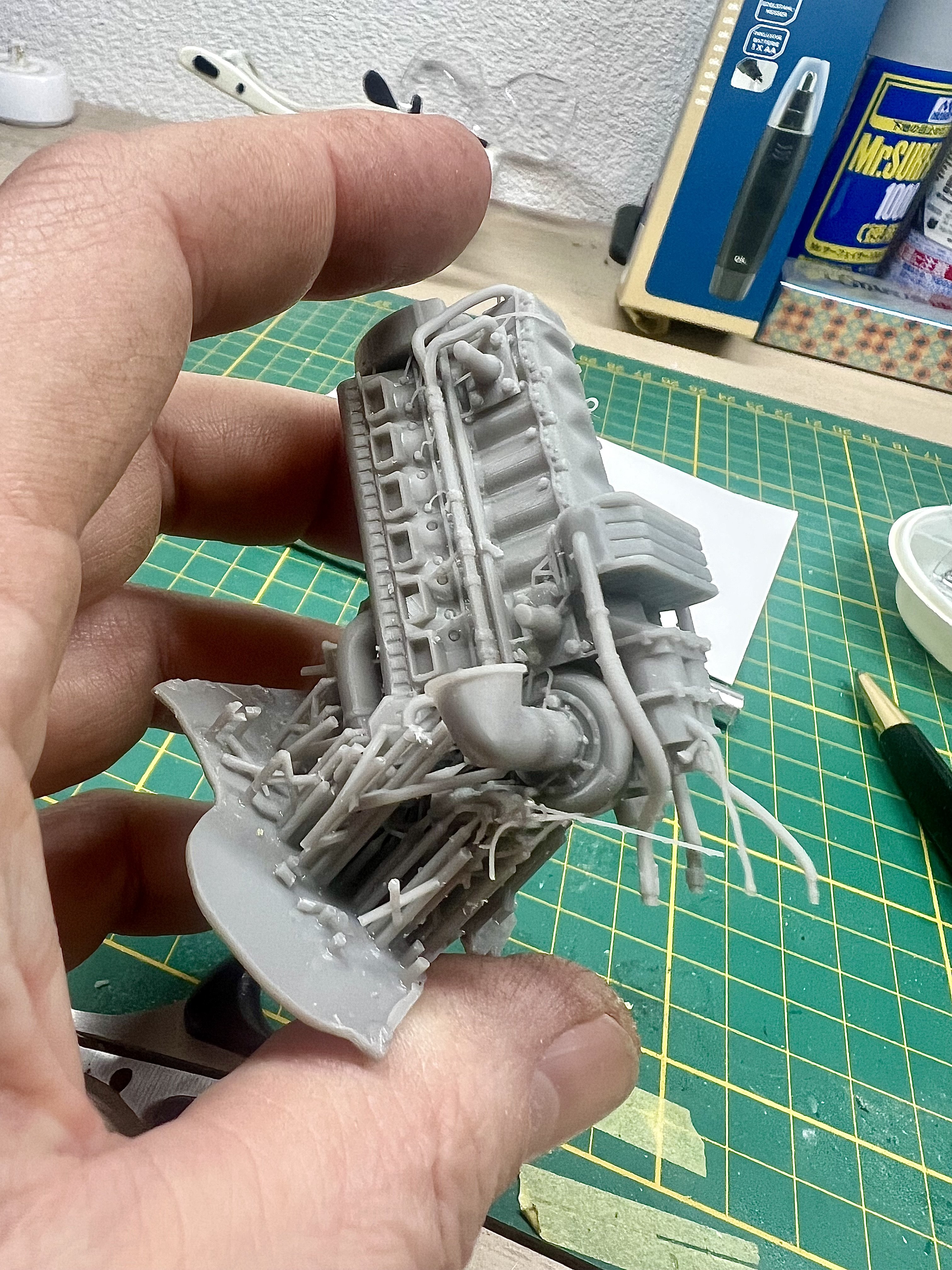
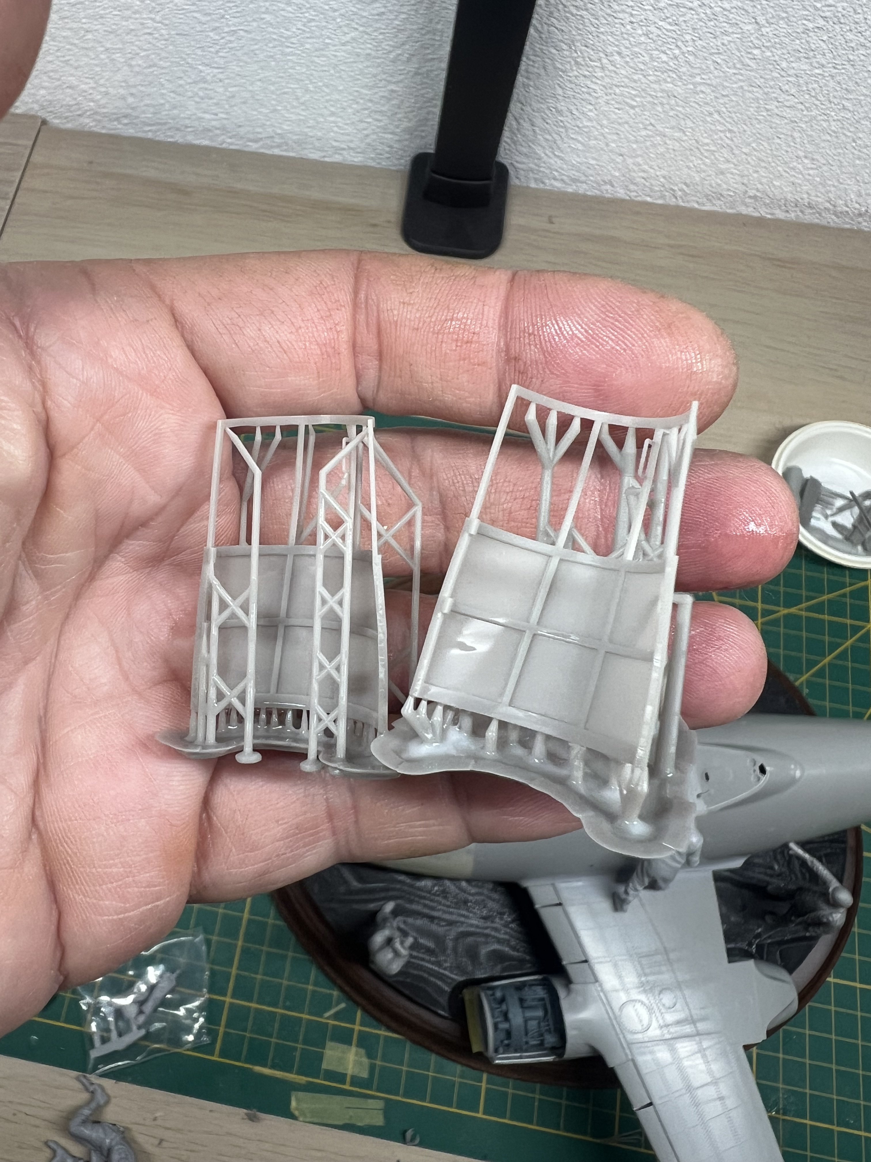
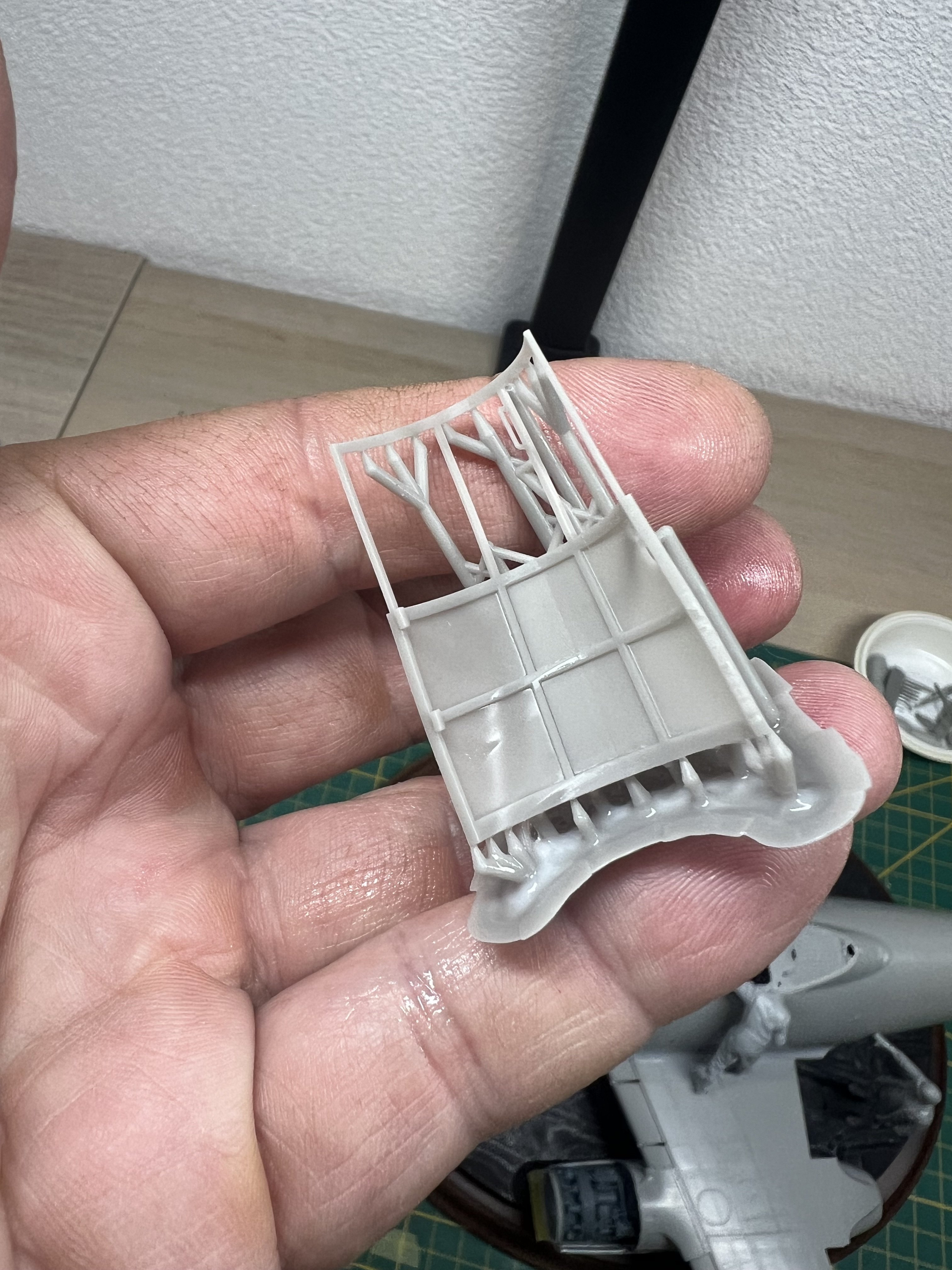
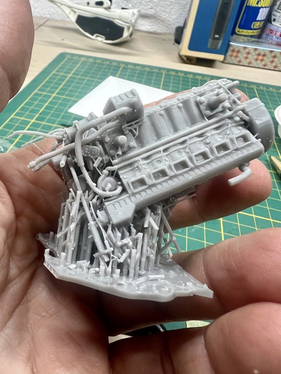
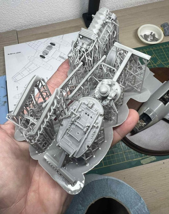
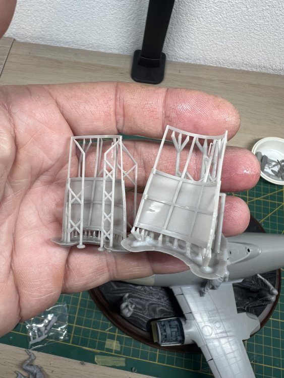
Freeing the Jumo from its supports takes longer than the 3 hour printing time. No joke. You have to be very careful not to snip off a cable or two.
-
1/32 Ju-87D Stuka
JeroenPeters replied to JeroenPeters's topic in LSM 1/35 and Larger Work In Progress
First plastic is cut. Now working on fhe inner frame that holds the hatch.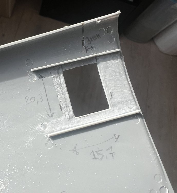
-
1/32 ME-262A-2a/U2
JeroenPeters replied to JeroenPeters's topic in LSM 1/35 and Larger Work In Progress
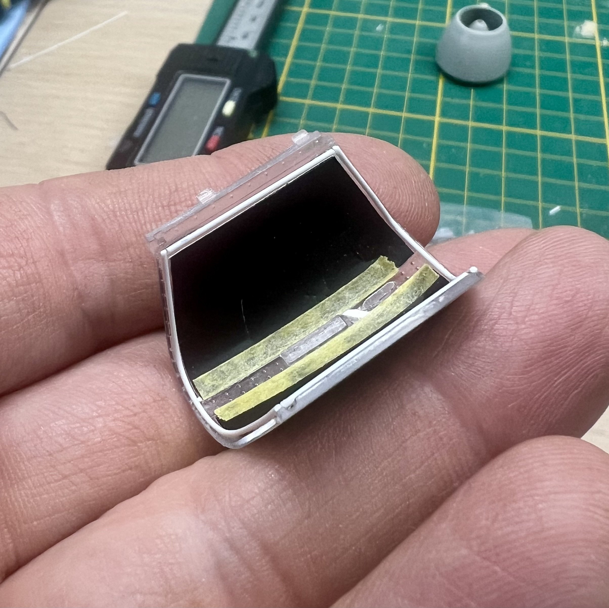
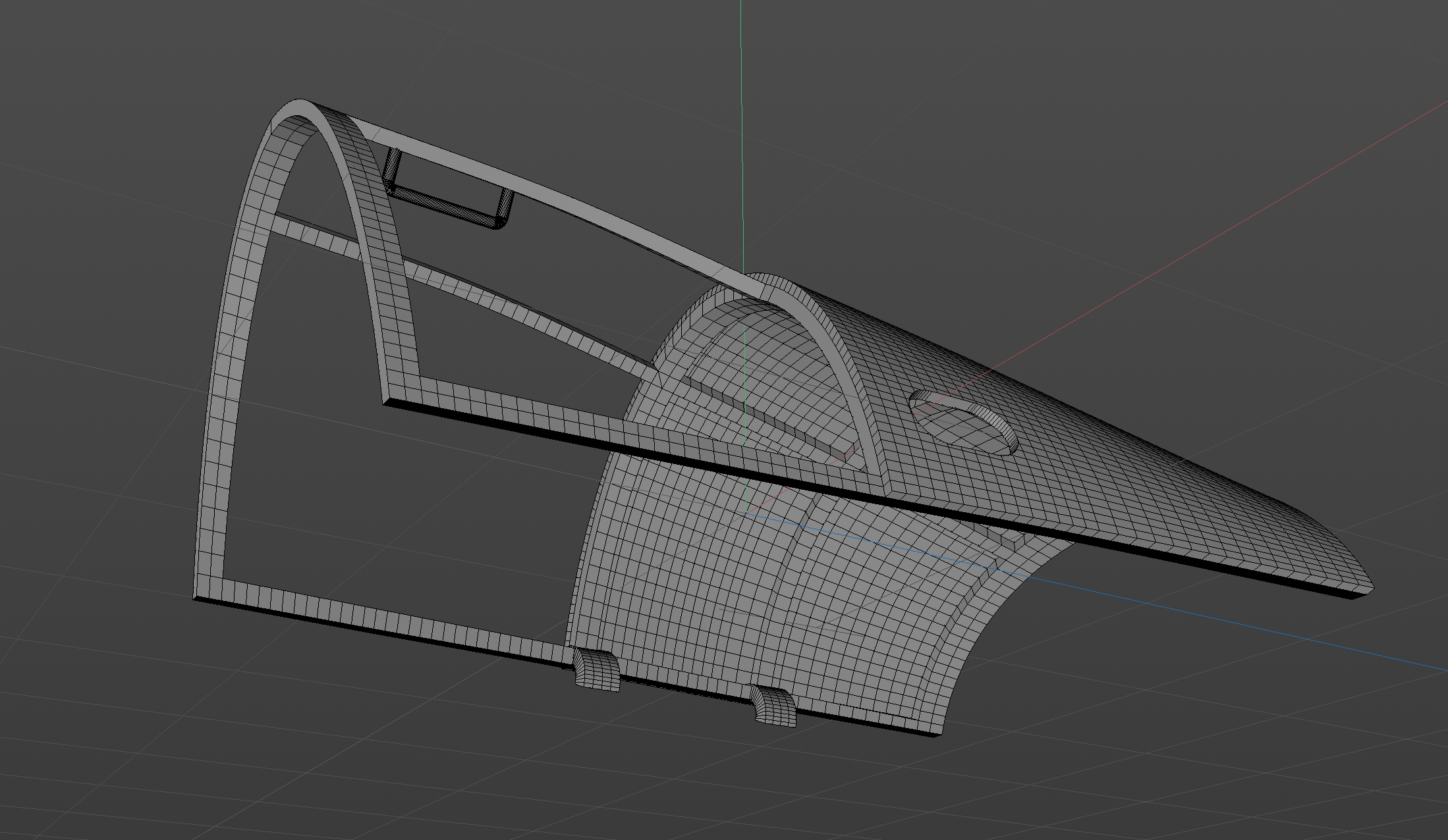
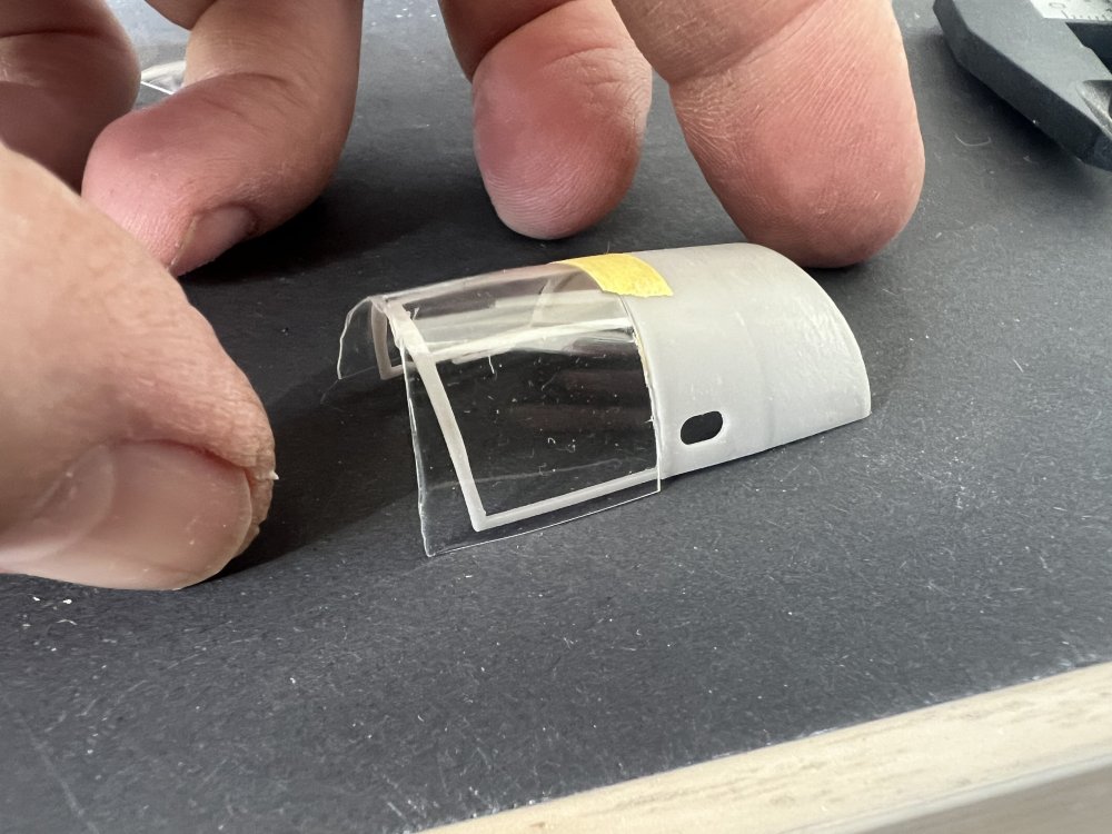
Finally after 20 tries i think i’m pleased. I made a ‘step’ in the upper canopy so that the transparent part becomes flush with the rear. If that makes sense. Need to cut and sand it so size, but this will work. Also made a few new nose glazing parts. This will be tricky-er.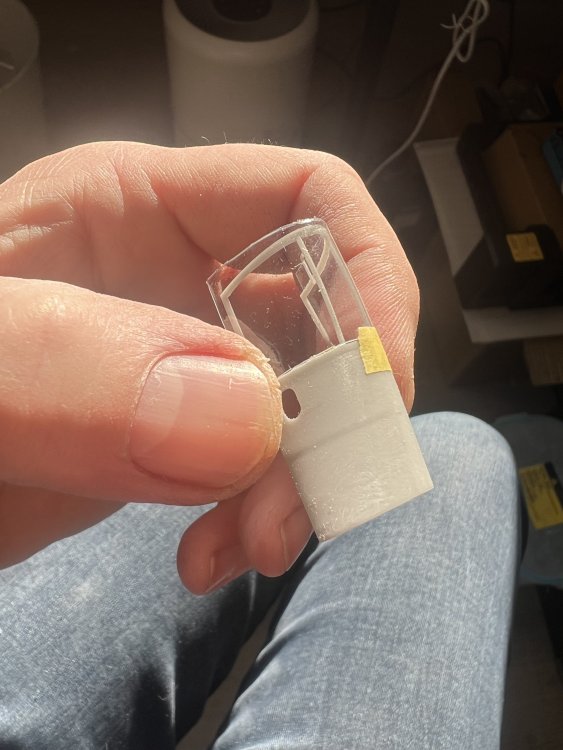
-
1/32 ME-262A-2a/U2
JeroenPeters replied to JeroenPeters's topic in LSM 1/35 and Larger Work In Progress
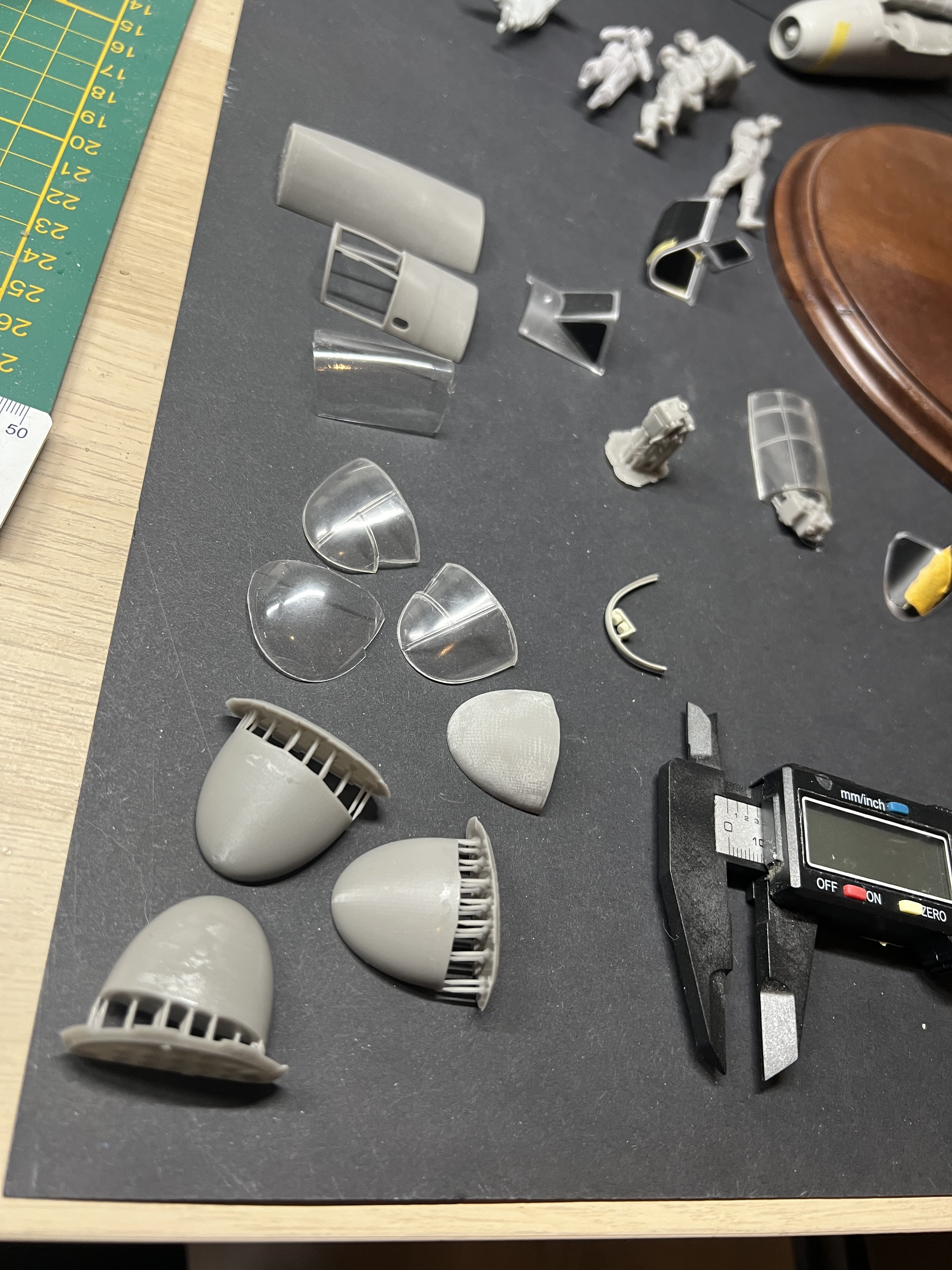
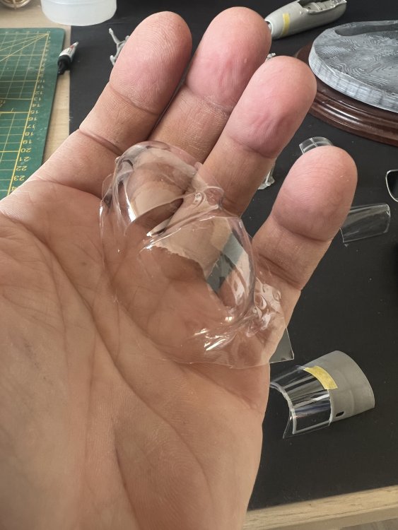
printing the vacform shapes to make the glass. Also polishing the hell out of the MDC glass, since i dont know what route is best. I’ll try both and go with the best.
-
1/32 Ju-87D Stuka
JeroenPeters replied to JeroenPeters's topic in LSM 1/35 and Larger Work In Progress
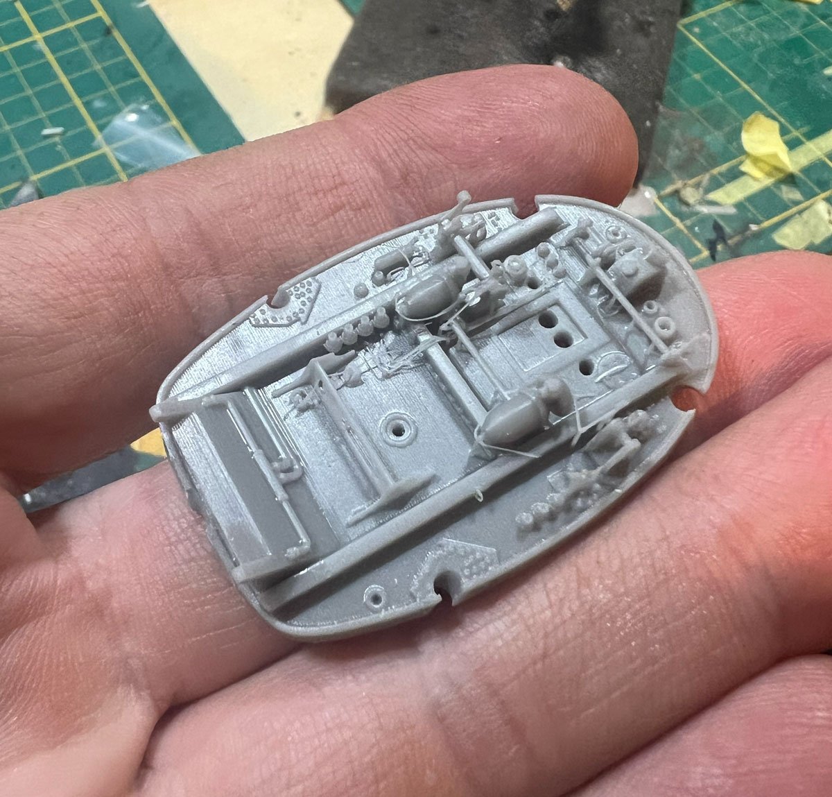
The detail on the Aladdin Models 3d file is actually intended for 1/12 scale. So if you shrink it down to 32nd scale, the detail is amazing. All the wires are there. Same on the engine itself. You really have to take care not to snip and off.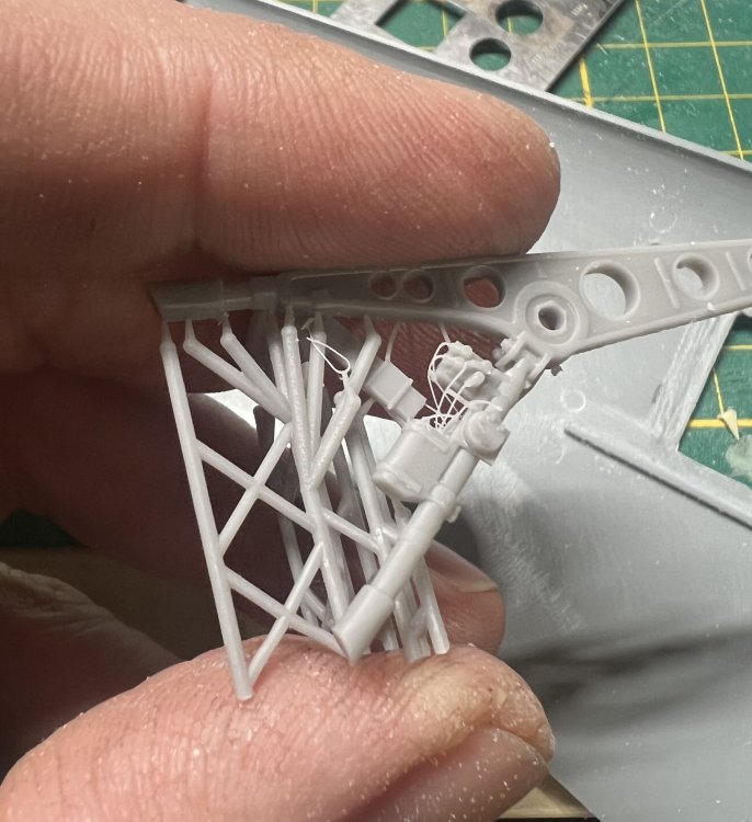
-
1/32 Ju-87D Stuka
JeroenPeters replied to JeroenPeters's topic in LSM 1/35 and Larger Work In Progress
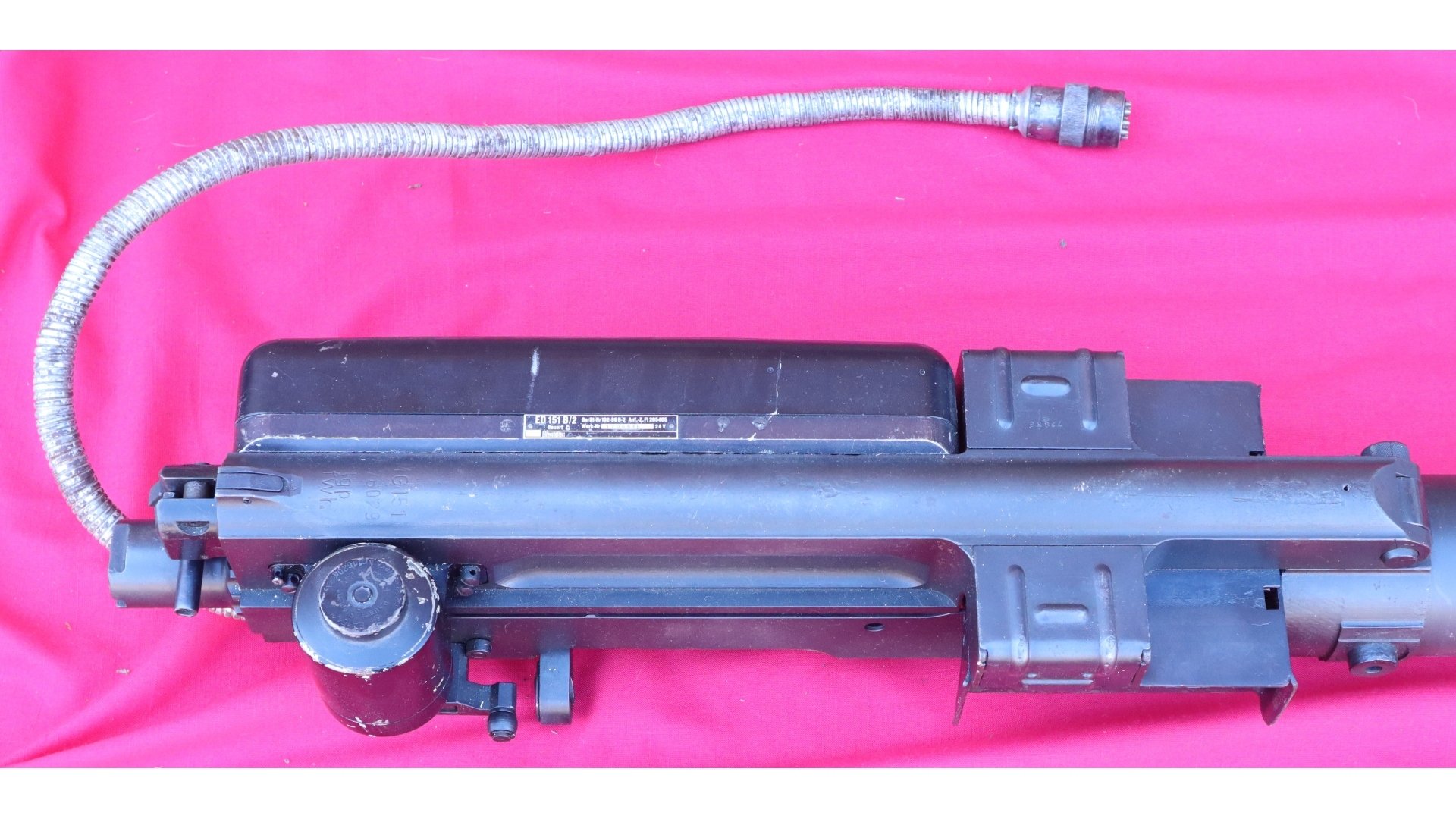
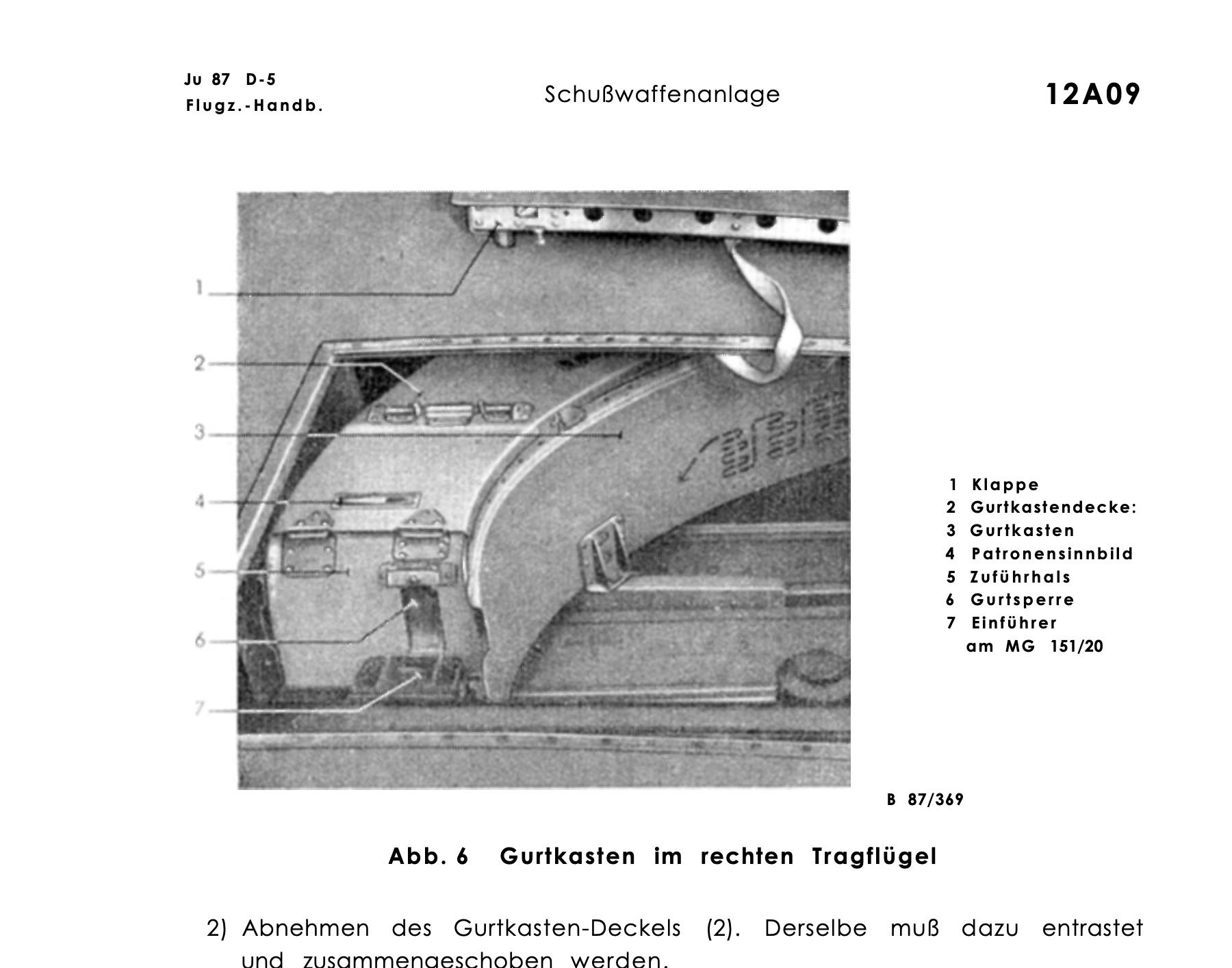
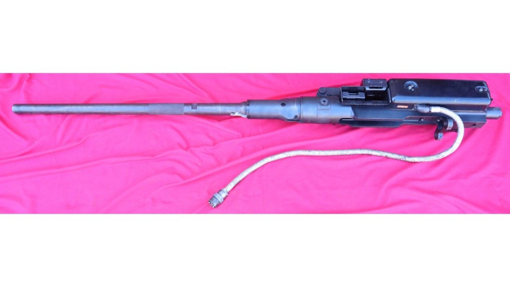
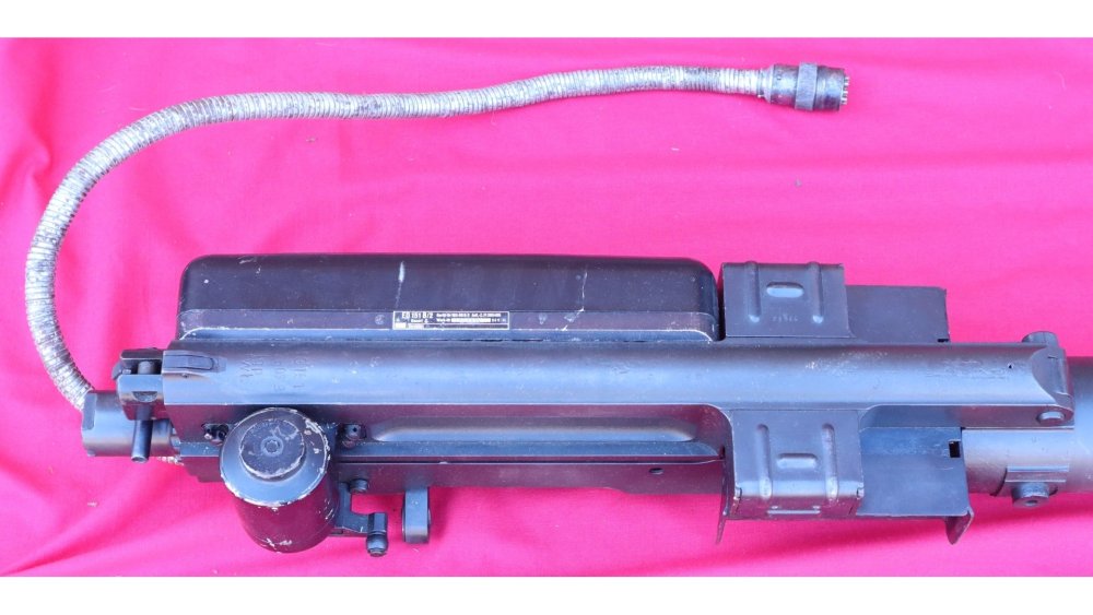
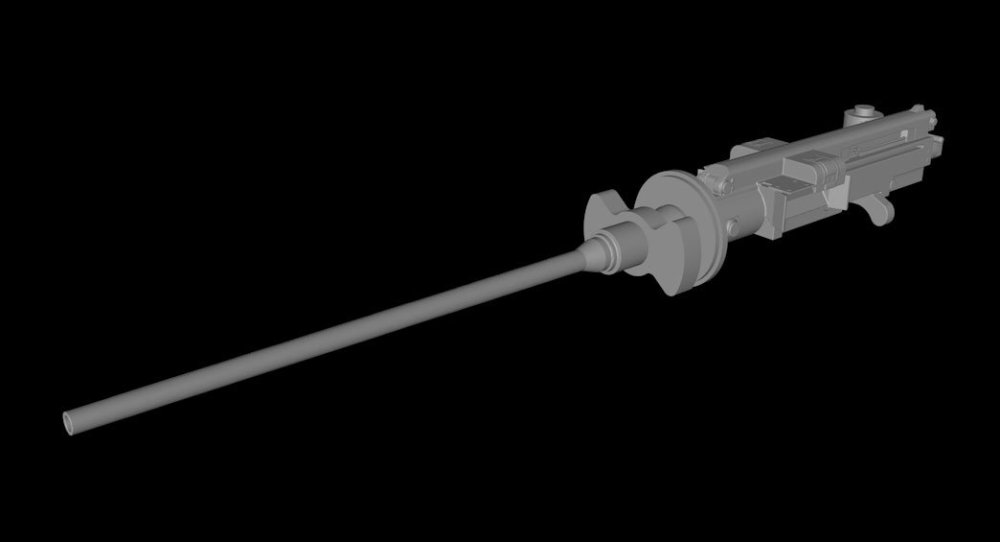
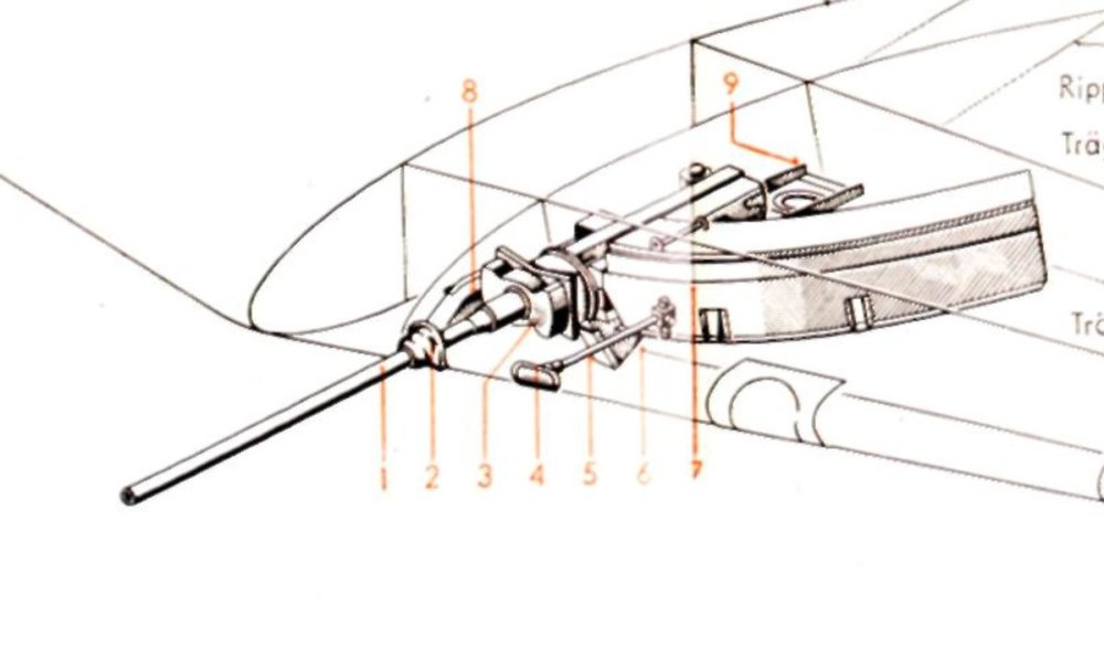
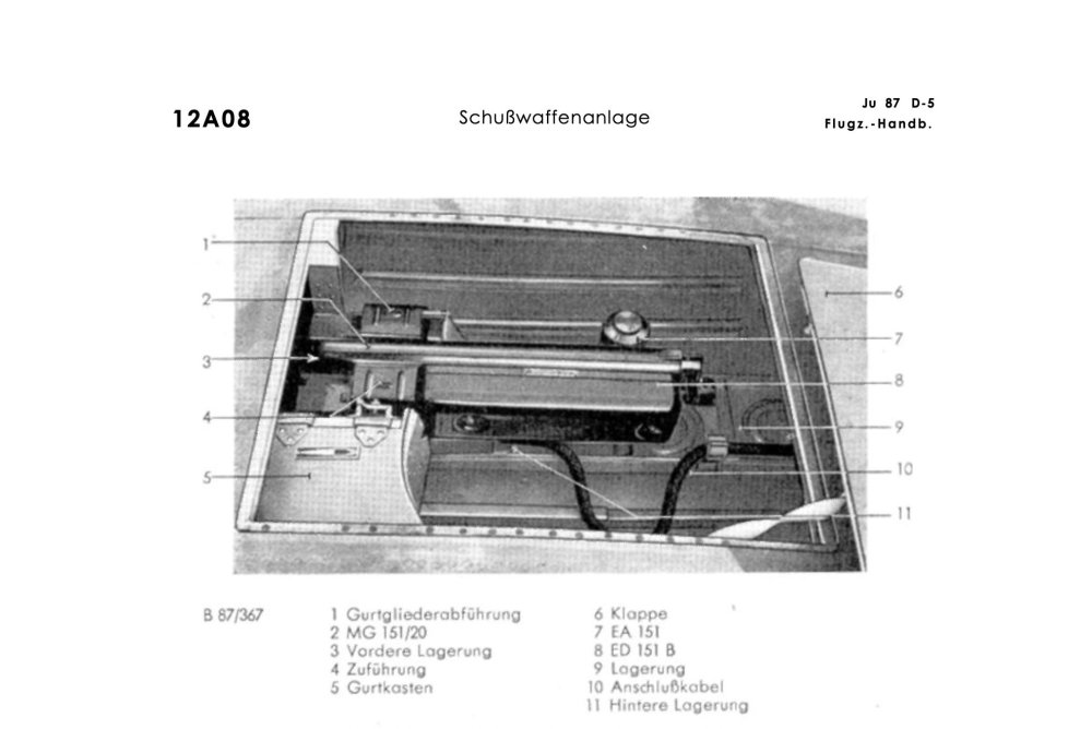
Added the ED151B unit to the left side of the MG151/20. I measured the gun bay hatch on the kit and the room there is for the gun bay. I found some Luftwaffe manuals on the Ju-87D and will figure out what is what.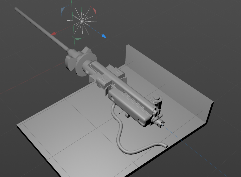
- 62 replies
-
- 11
-

-
1/32 Ju-87D Stuka
JeroenPeters replied to JeroenPeters's topic in LSM 1/35 and Larger Work In Progress
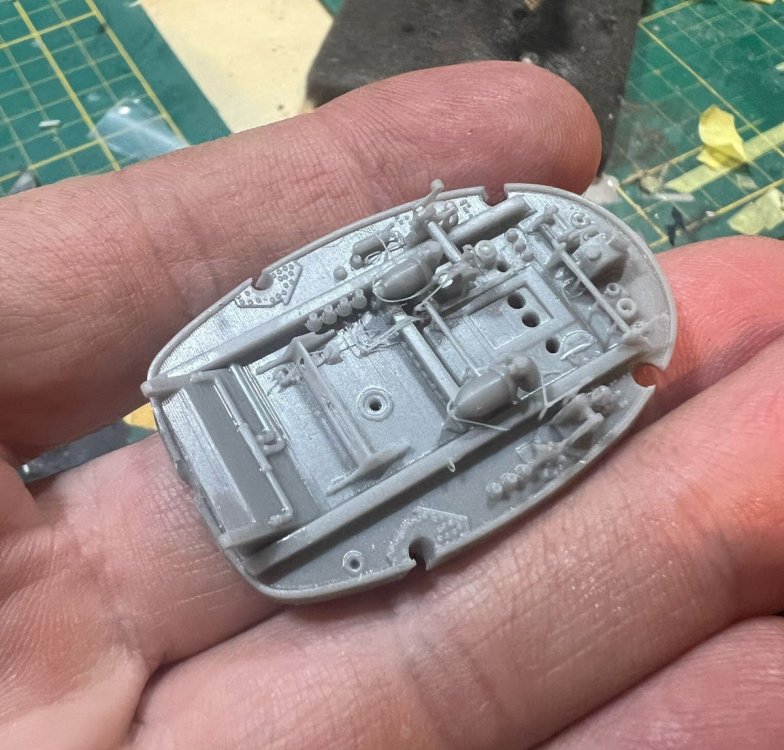
First 3d print of engine. The firewall needs adjustments, but for a first try I am pretty pleased.
- 62 replies
-
- 11
-
-
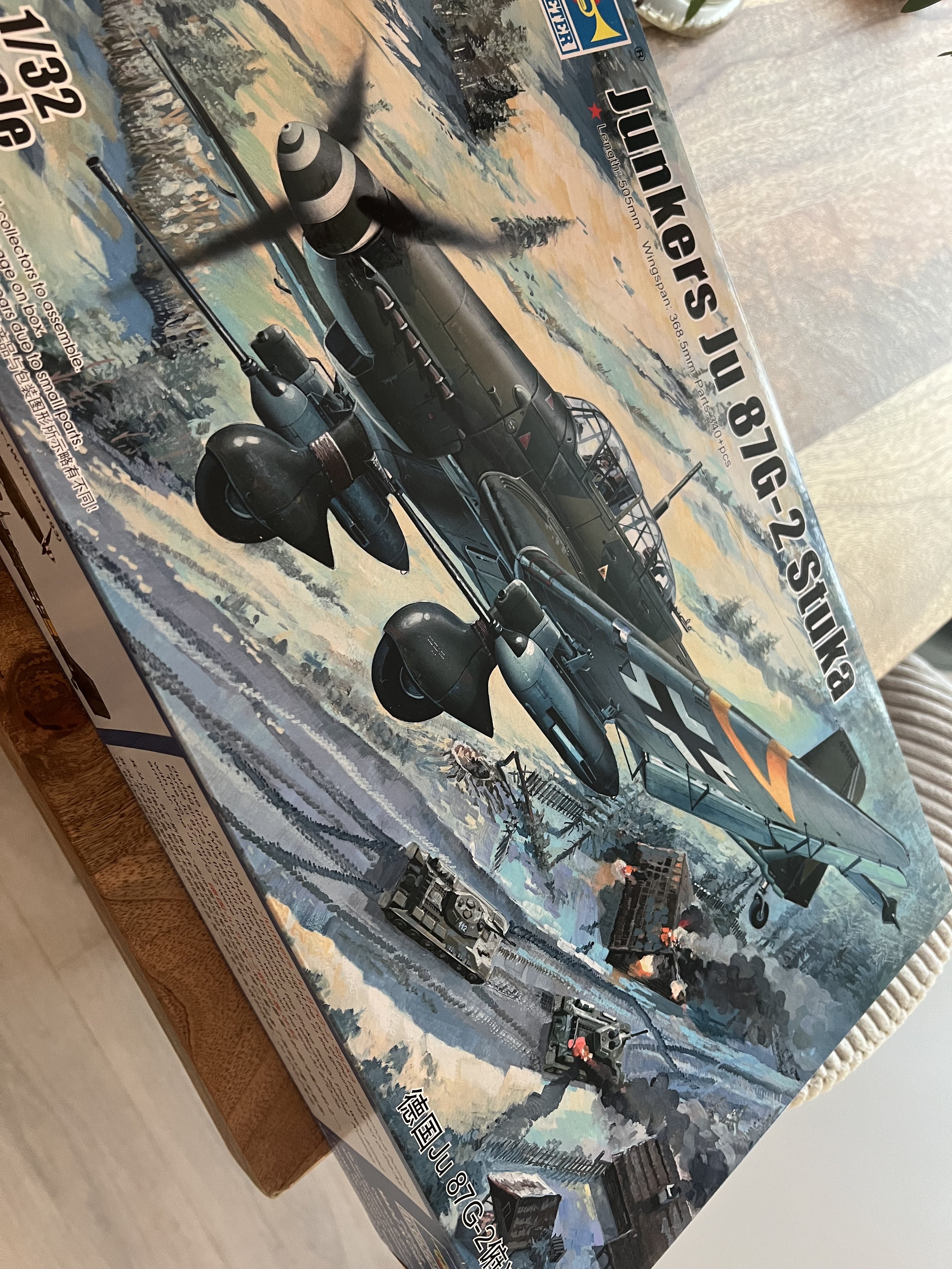
Hi all, Fellow member Martinnfb remembered I said one day I was interested in building a Stuka once. He was insanely kind to gift me a Hasegawa Ju-87D-8 he had in the stash. Not shying away from building multiple projects at the same time I started flipping through my Stuka books. I have an idea, but it's not crystal clear yet. I feel like building two piled up Stuka's with all panels open. I might change my mind a couple of times. A bought the Aladdin models 3d model of a Jumo 211 engine. It has the B radiator hanging underneath, but I will 3D print what I need to make it a souped up version for the Ju-87D. Meanwhile I am researching the Mg151/20 wing guns and 3D drawing the gun bays. This will actually be the easiest part. Aires cockpit is ordered. 1Manarmy masks. HGW seatbelts. Eduard exterior.

-
1/32 ME-262A-2a/U2
JeroenPeters replied to JeroenPeters's topic in LSM 1/35 and Larger Work In Progress
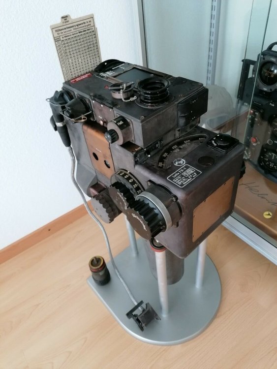
In this photo you can see the extractable chart... extracted from the metal case at the head of the bombsight.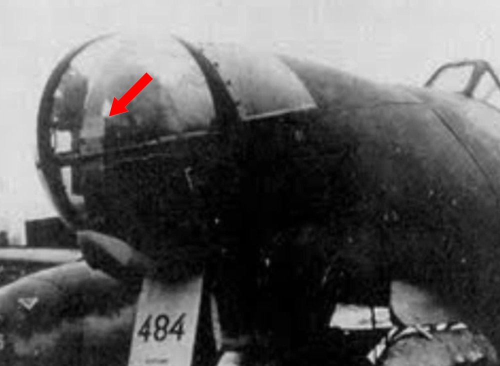
-
1/32 ME-262A-2a/U2
JeroenPeters replied to JeroenPeters's topic in LSM 1/35 and Larger Work In Progress
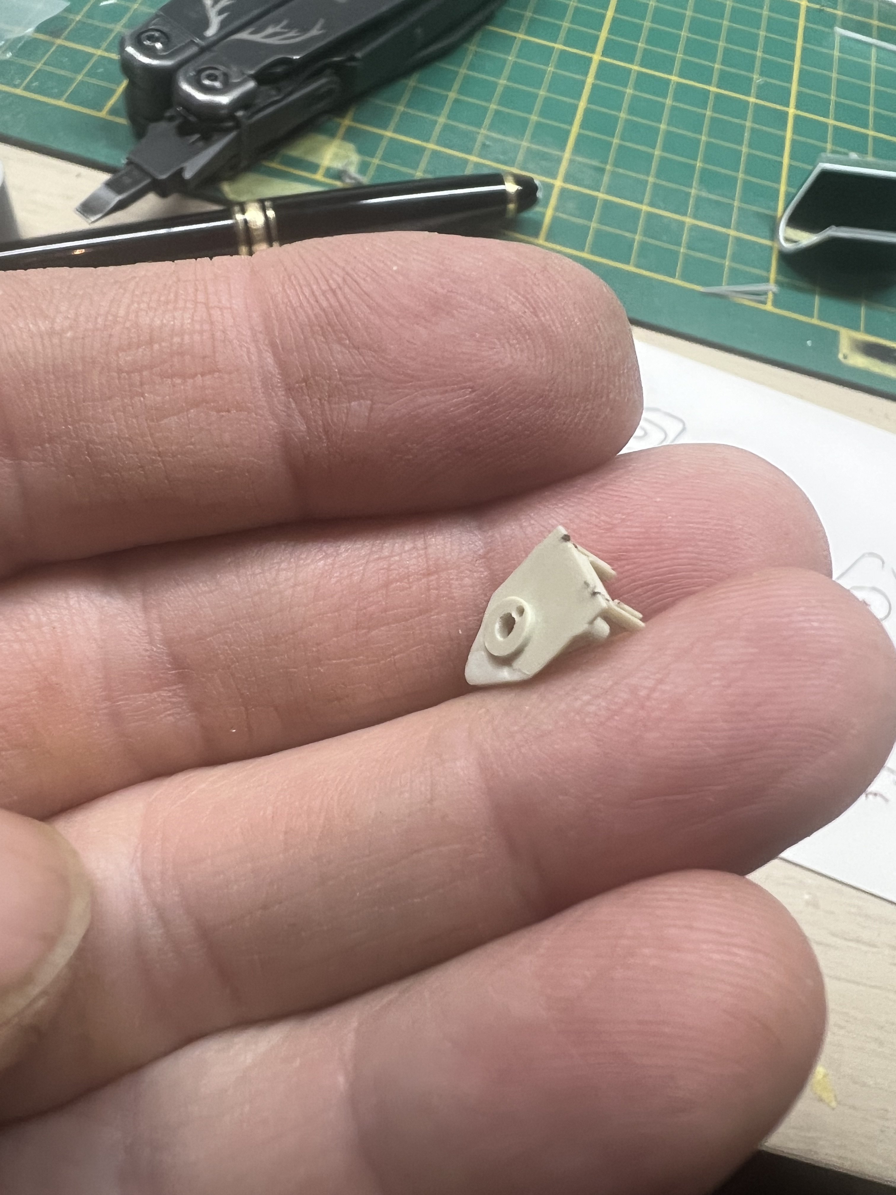
Lofte bombsight with bracket printed. Huge improvement over MDC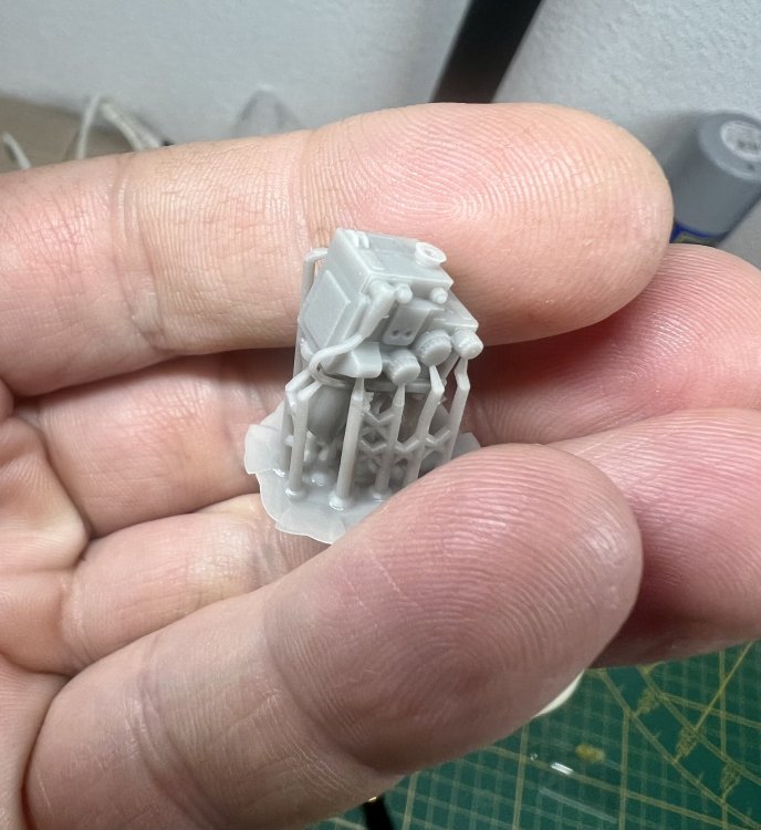
-
1/32 ME-262A-2a/U2
JeroenPeters replied to JeroenPeters's topic in LSM 1/35 and Larger Work In Progress
Pretty easy i reckon. 3D design a tailwheel well, tailwheel and doors. Close up the nose and delete the nose gear door seams. And probably some other bits and bobs. -
1/32 ME-262A-2a/U2
JeroenPeters replied to JeroenPeters's topic in LSM 1/35 and Larger Work In Progress
Drew the bracket and started adding the wiring and bomb release 'remote'. Already printed the Lofte bombsight a few times, but I'm siure the new printer gives better detail.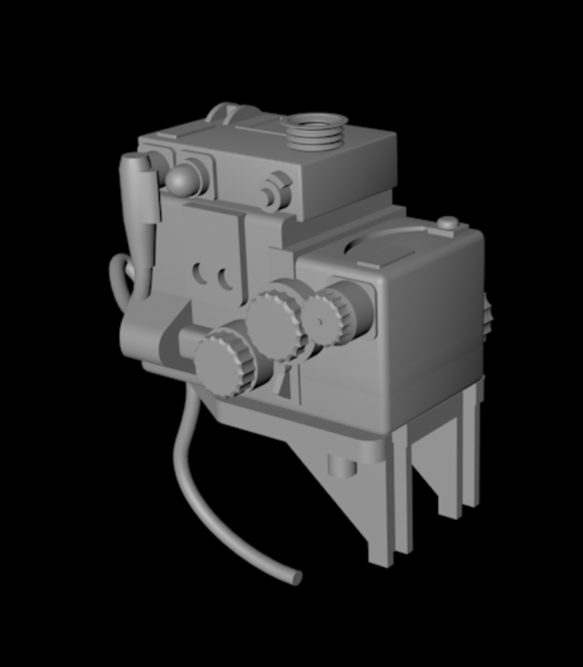
-
1/32 ME-262A-2a/U2
JeroenPeters replied to JeroenPeters's topic in LSM 1/35 and Larger Work In Progress
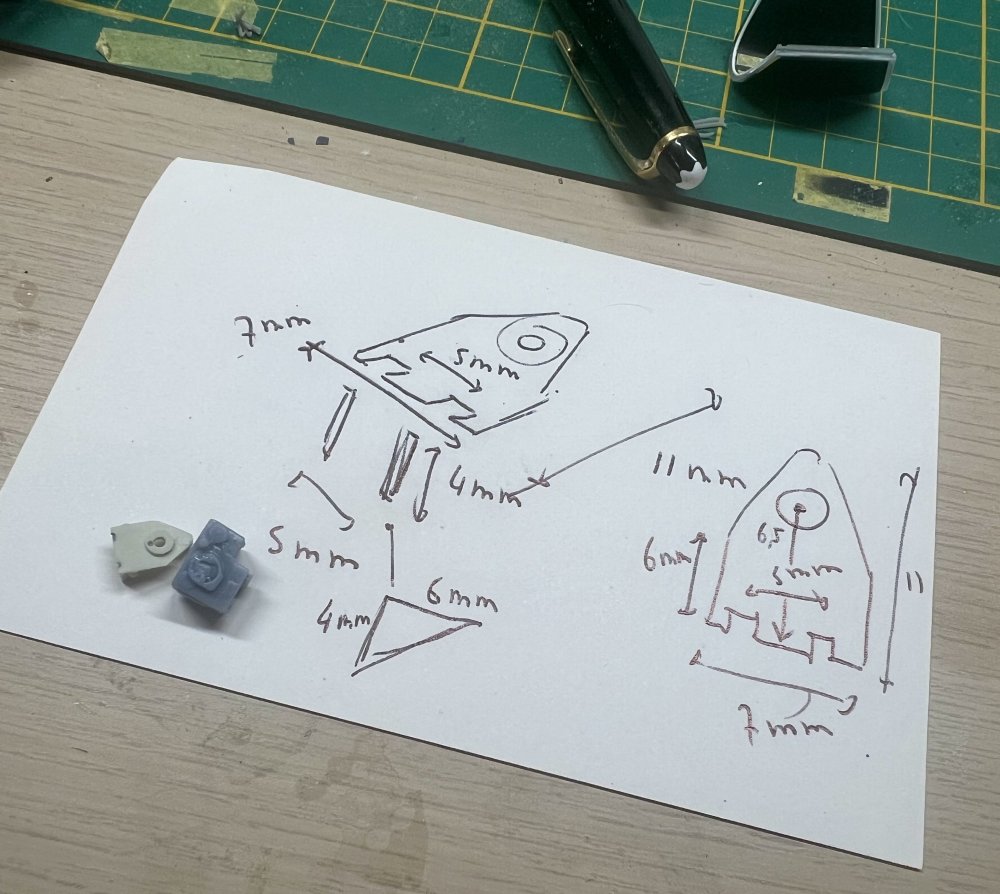
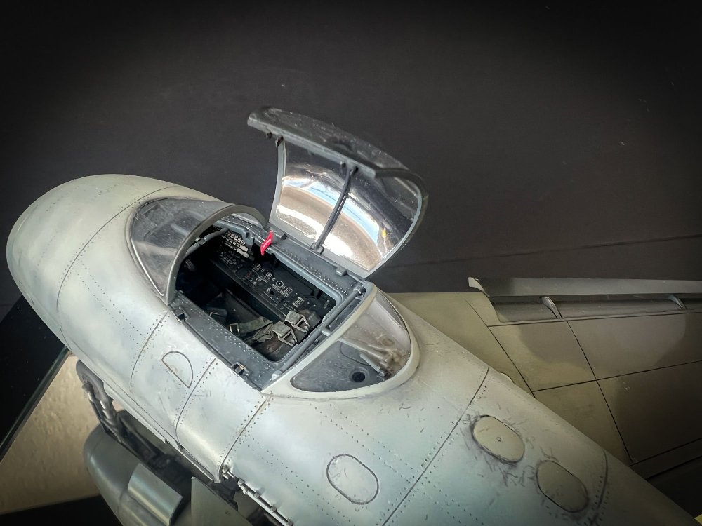
Reprinting the canopy tomorrow, together with a positive vacform shape to fashion the glass. The canopy needed to be 1mm longer. Adding tubular framing to the inside of the canopy hood and need to add the lock and handhold. Also having to 3d model the gunsight bracket. Seriously every single MDC part is bend, foggy, shrunken, etc.
-
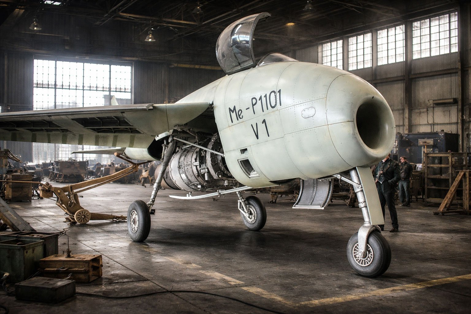
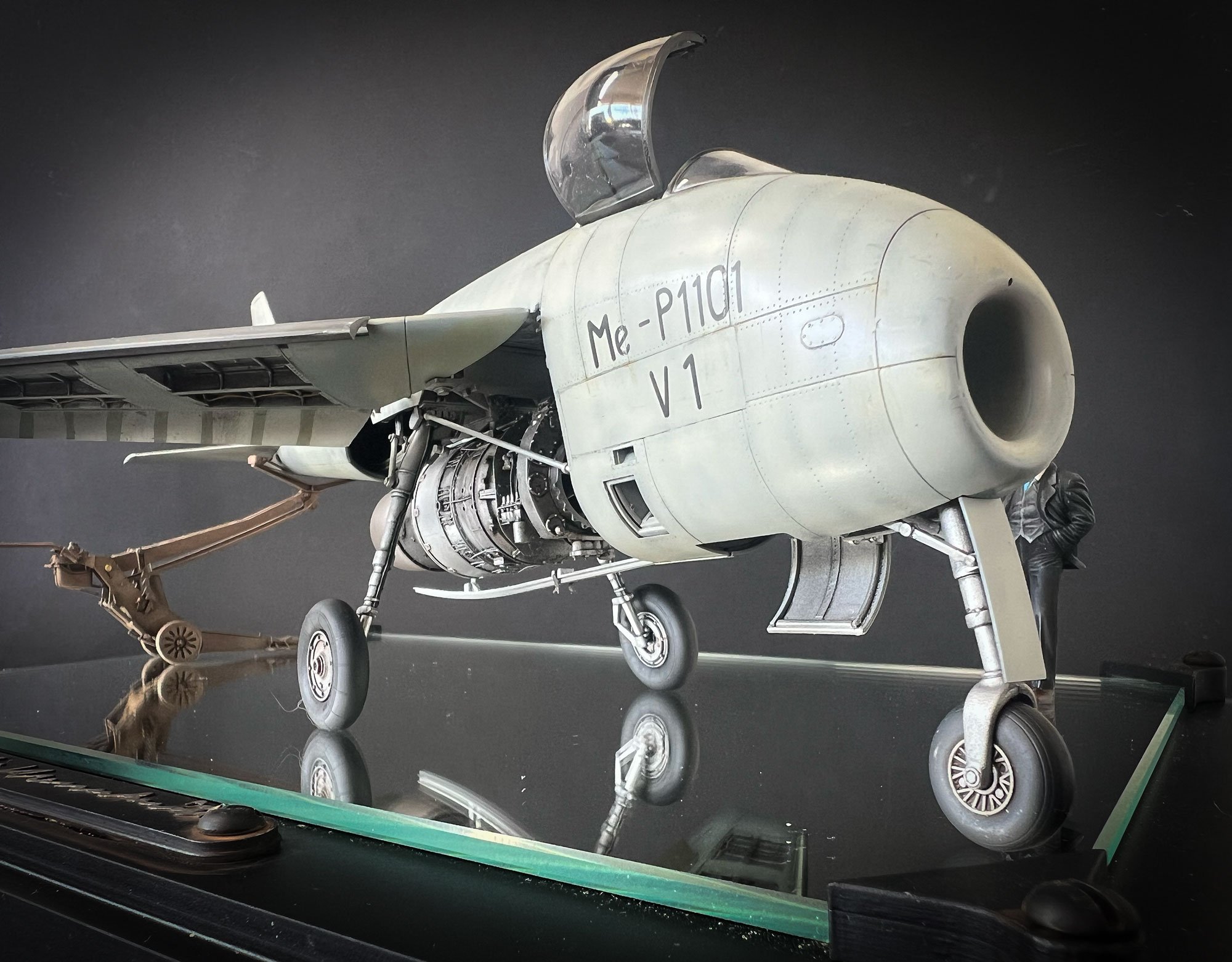
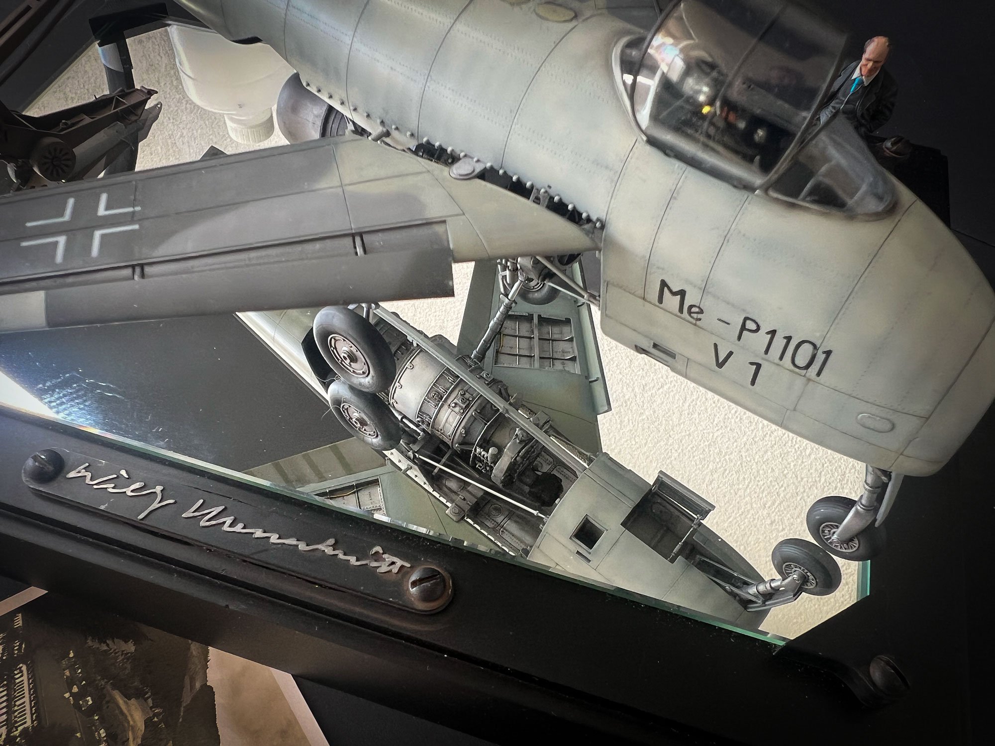
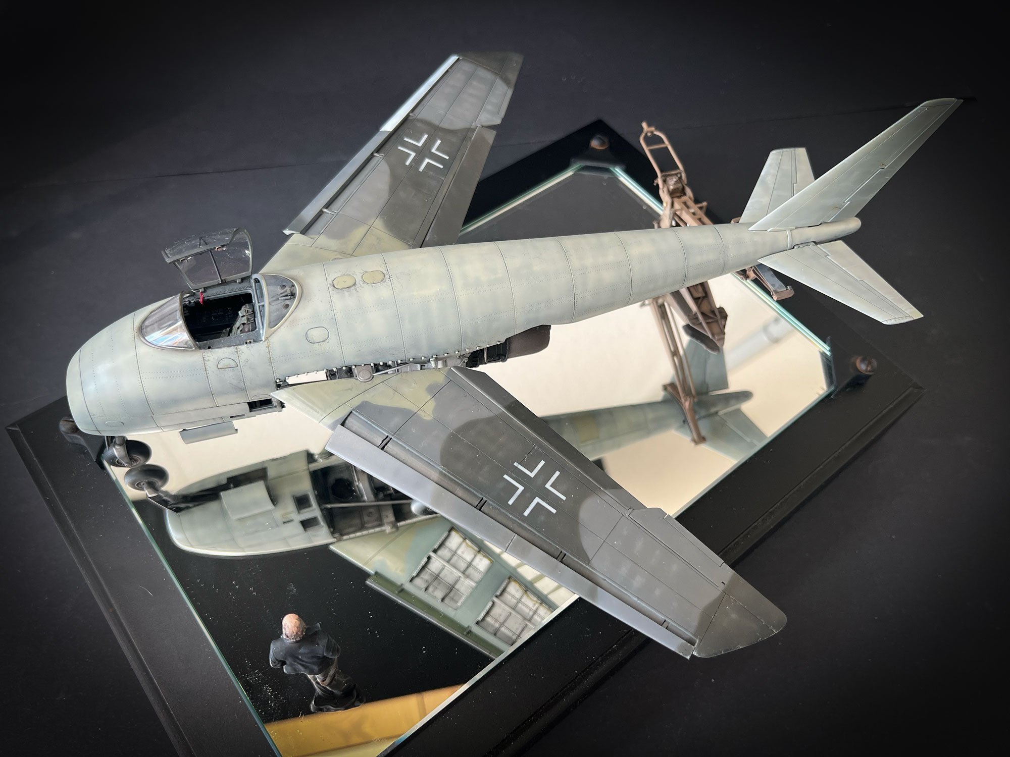
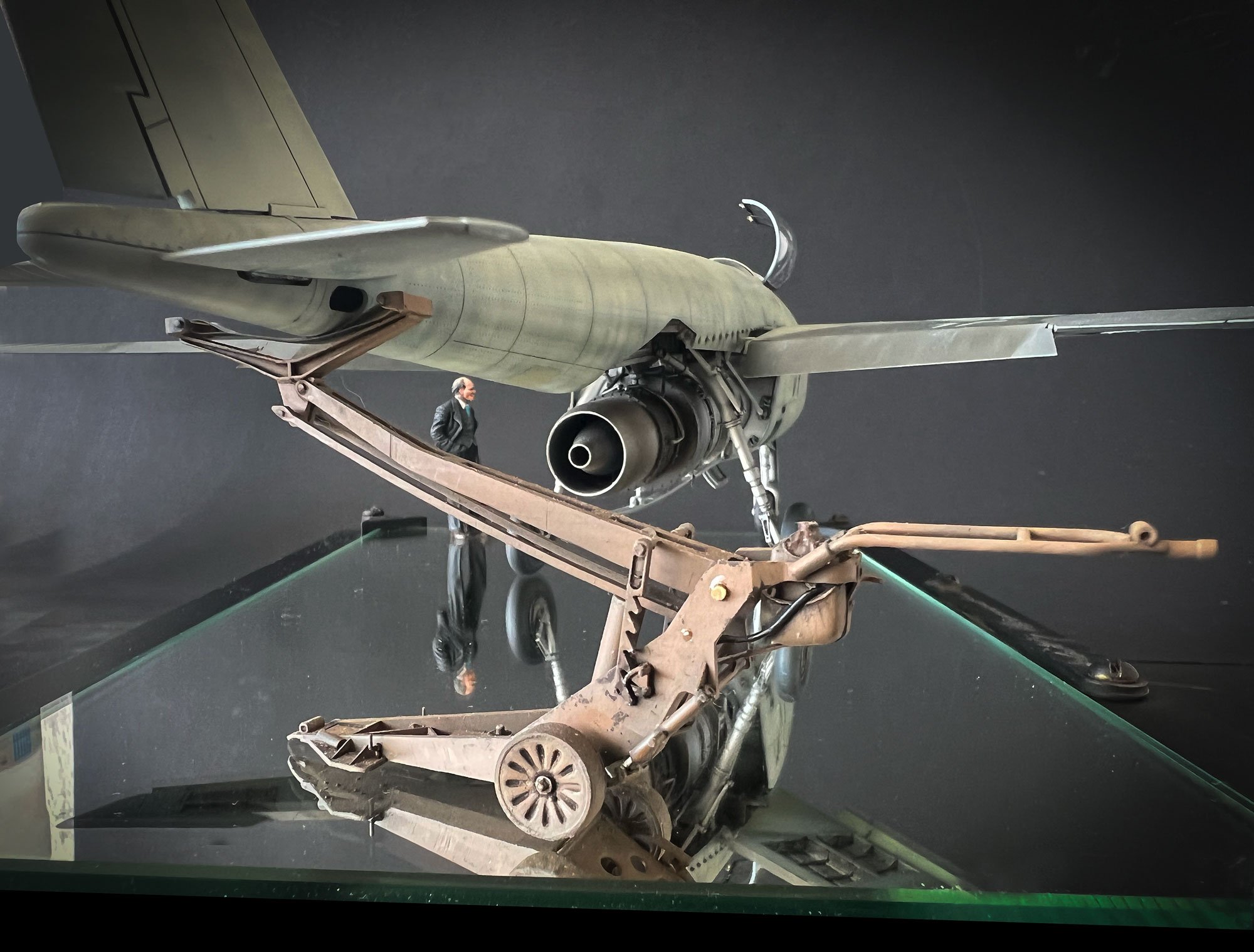
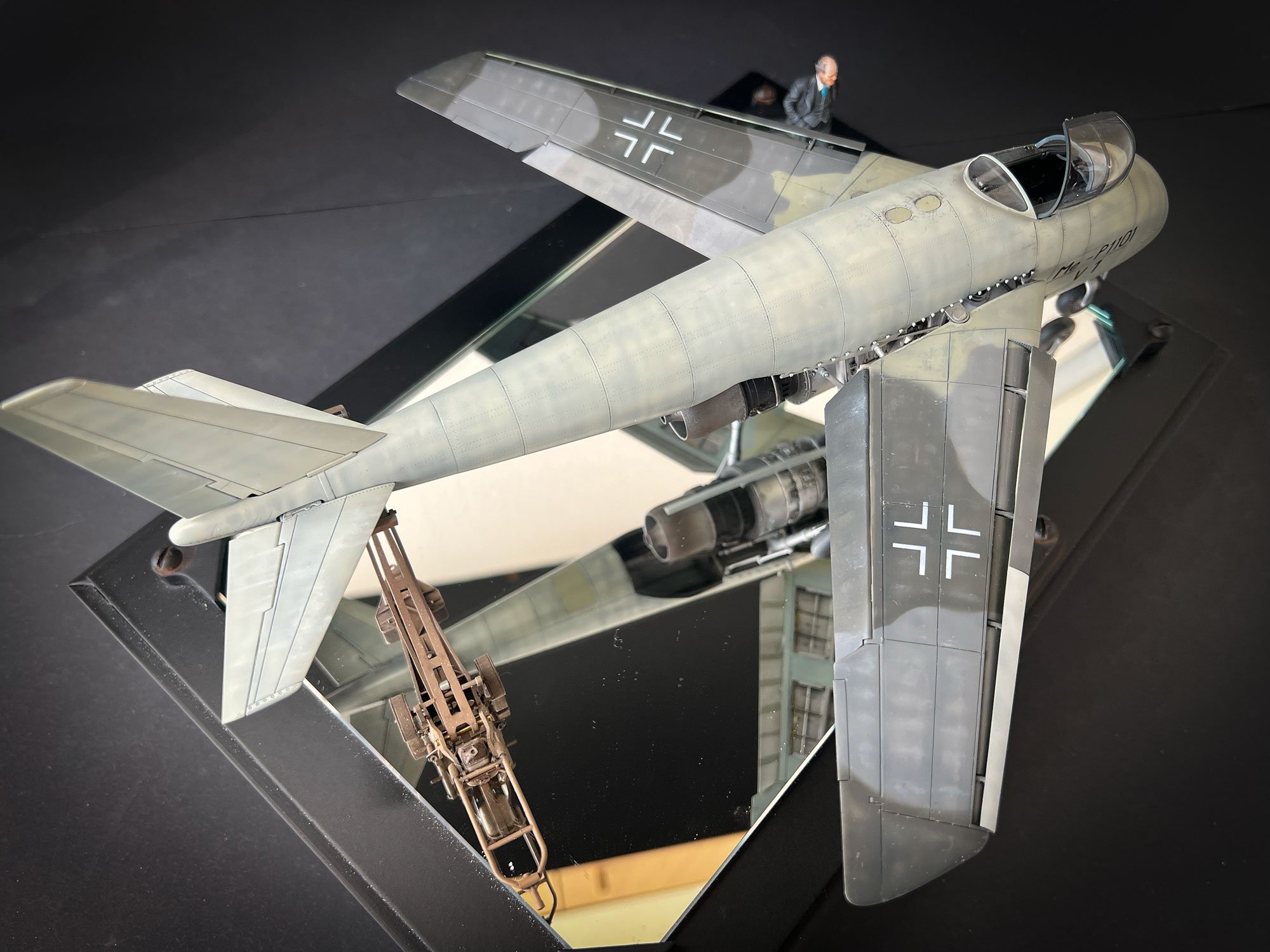
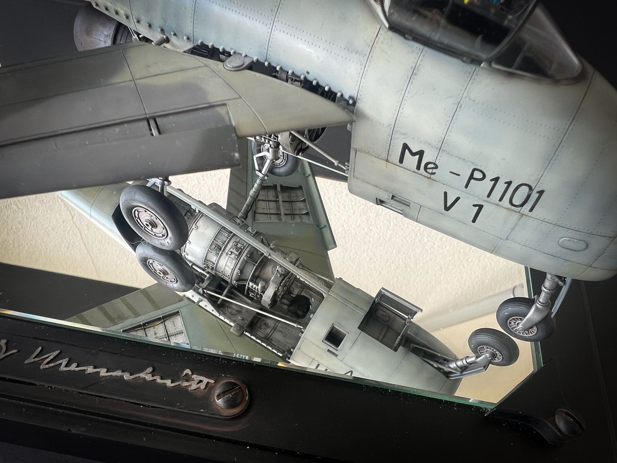
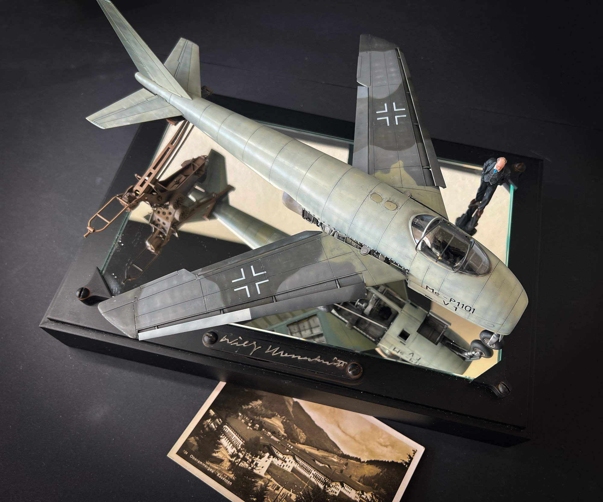
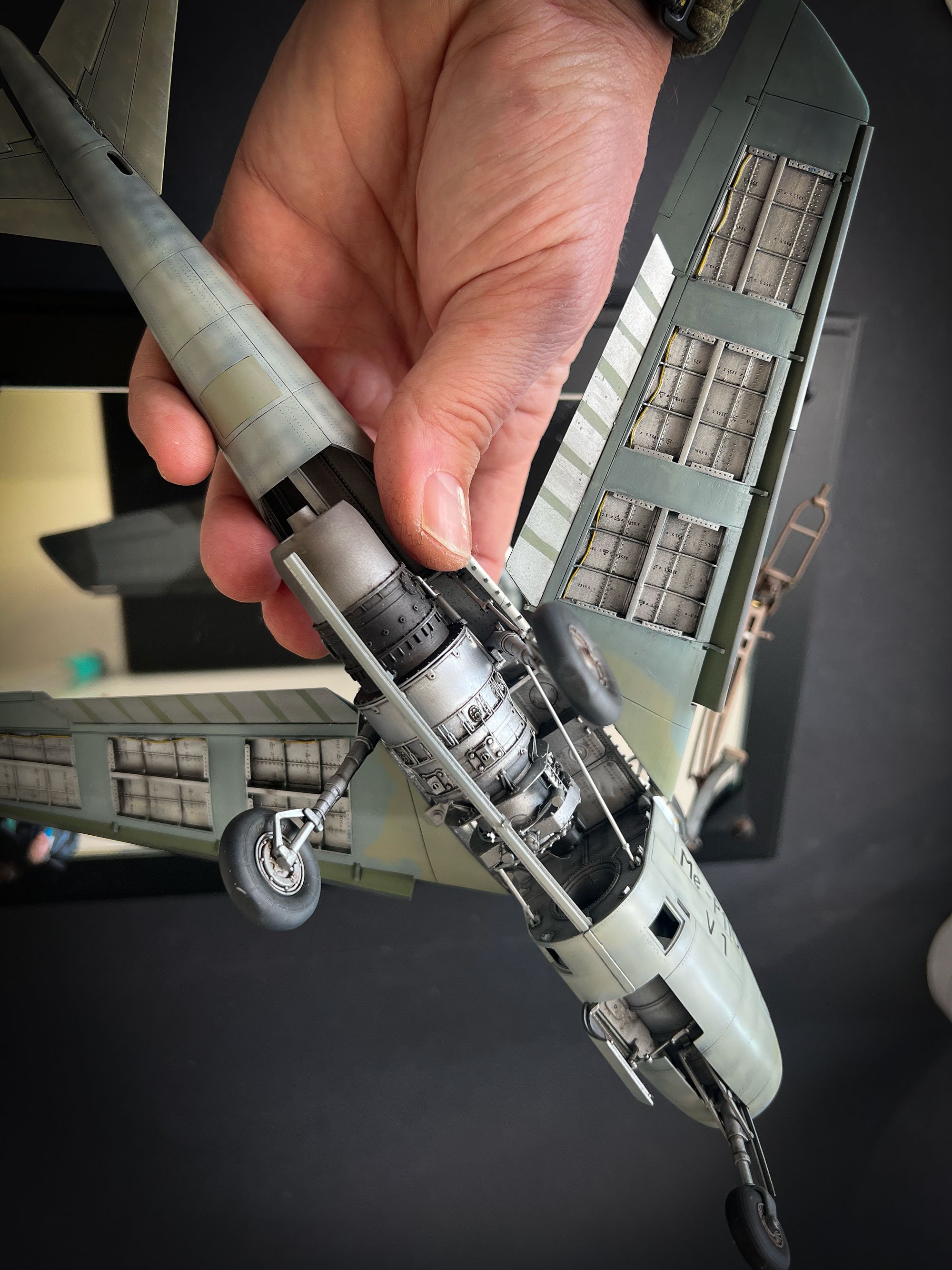
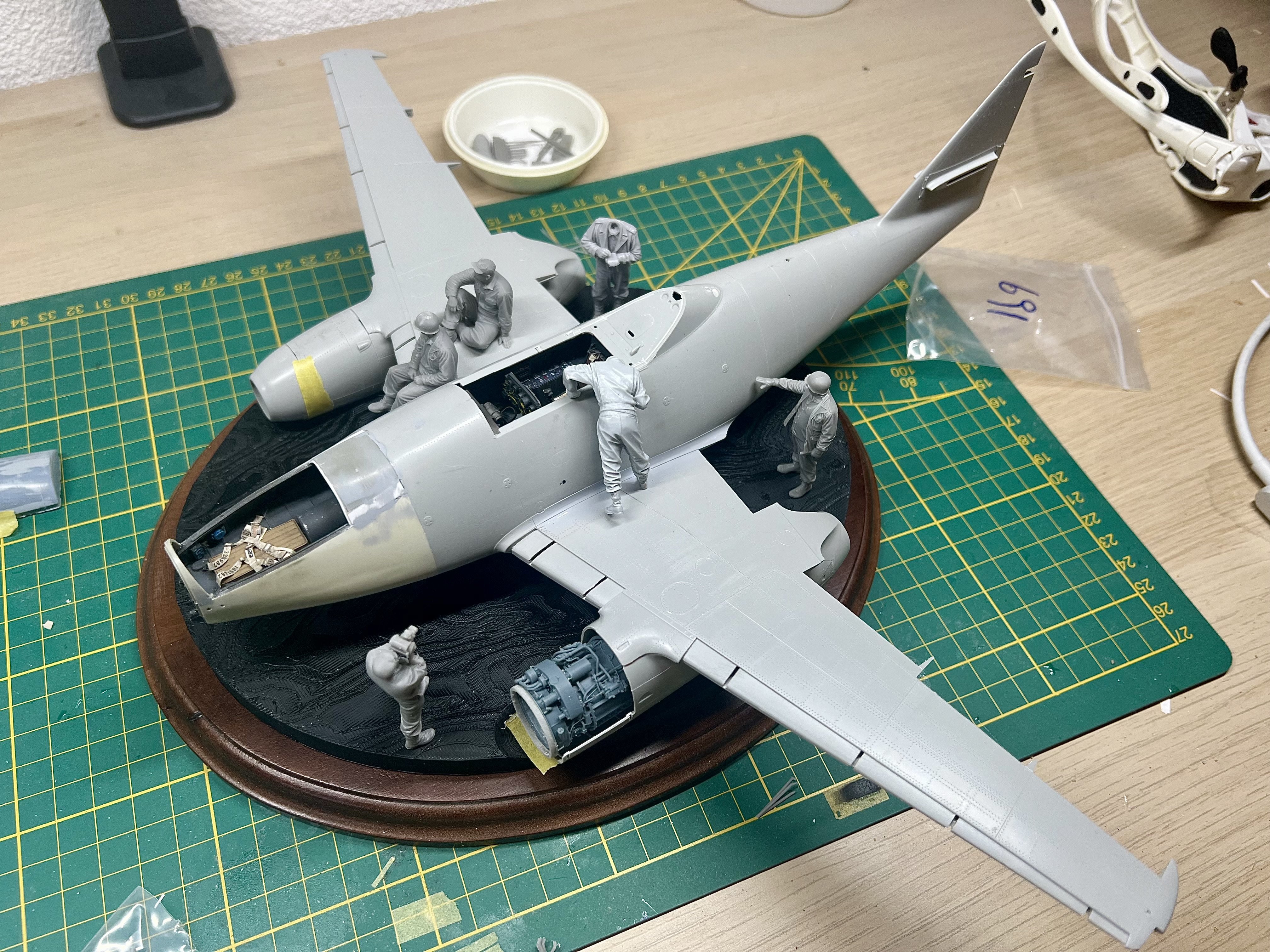
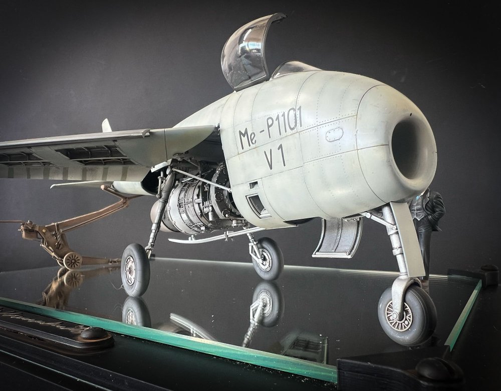
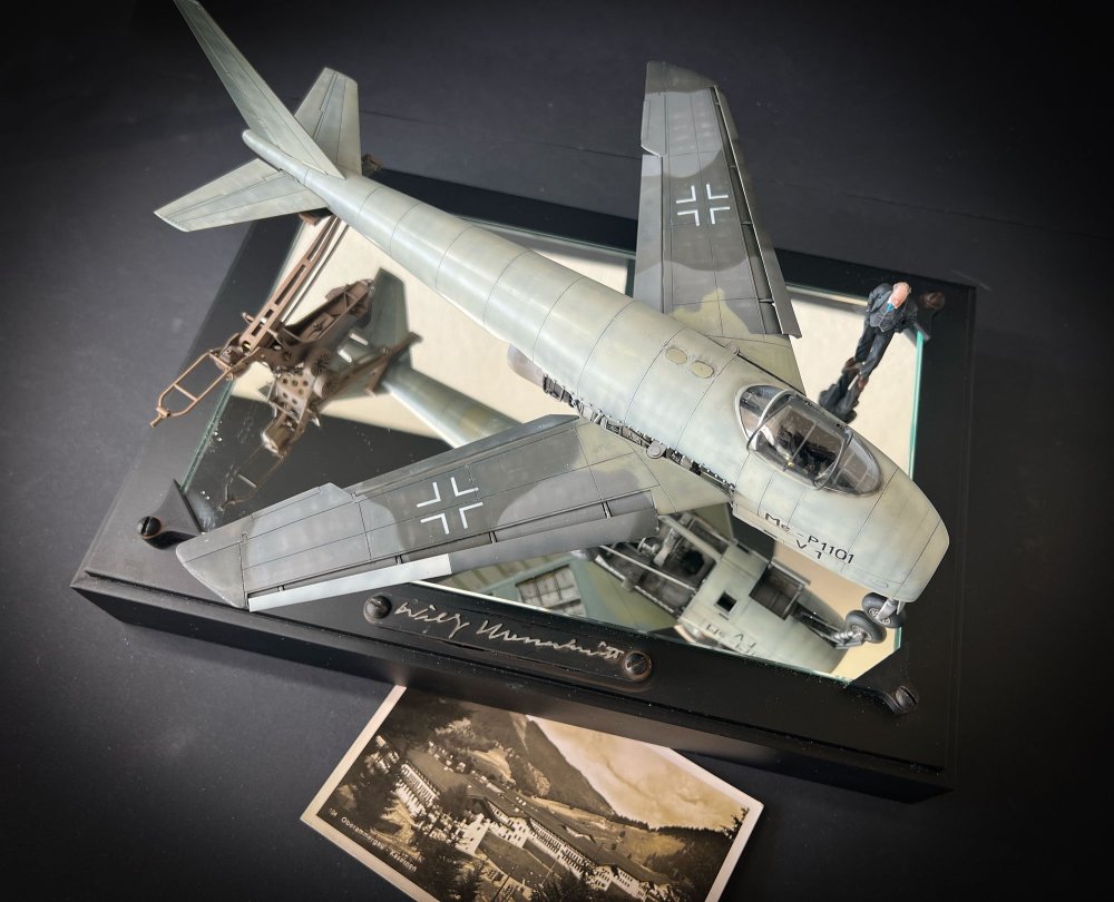
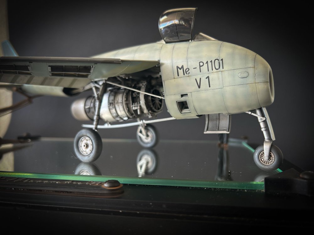
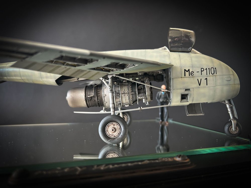
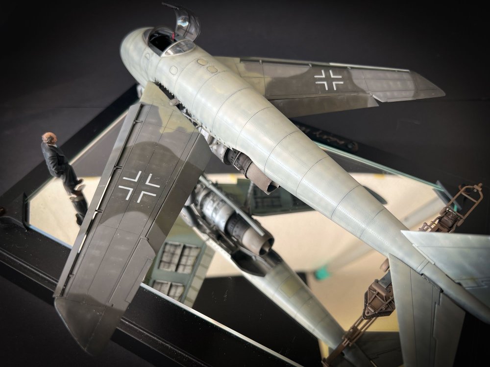
Hi all, made some 'proper' pics of my finished model. It has been modelled exactly (as far as my research could reach) as the mockup that was found at Oberammergau. The tail is lifted to prevent tail sitting (it had no guns so the balance was off) by a Herkules II bomb lift. This bomb lift was completely 3D designed and printed. The wings had open panels on the underside, so I 3D drew the internal detail. Many thanks to Pete Hamann! The limited amount of markings were done with the always excellent 1ManArmy masks. The HeS011 engine is a 3D printed engine from FPW model. HGW seatbelts of course. And some Eduard photo etch for the cockpit taken from a Me262. And an ArtScale seat. The figure of Willy Messerschmitt was created with Ai 3D software and printed.


-
1/32 ME-262A-2a/U2
JeroenPeters replied to JeroenPeters's topic in LSM 1/35 and Larger Work In Progress


- 167 replies
-
- 10
-
-
1/32 ME-262A-2a/U2
JeroenPeters replied to JeroenPeters's topic in LSM 1/35 and Larger Work In Progress
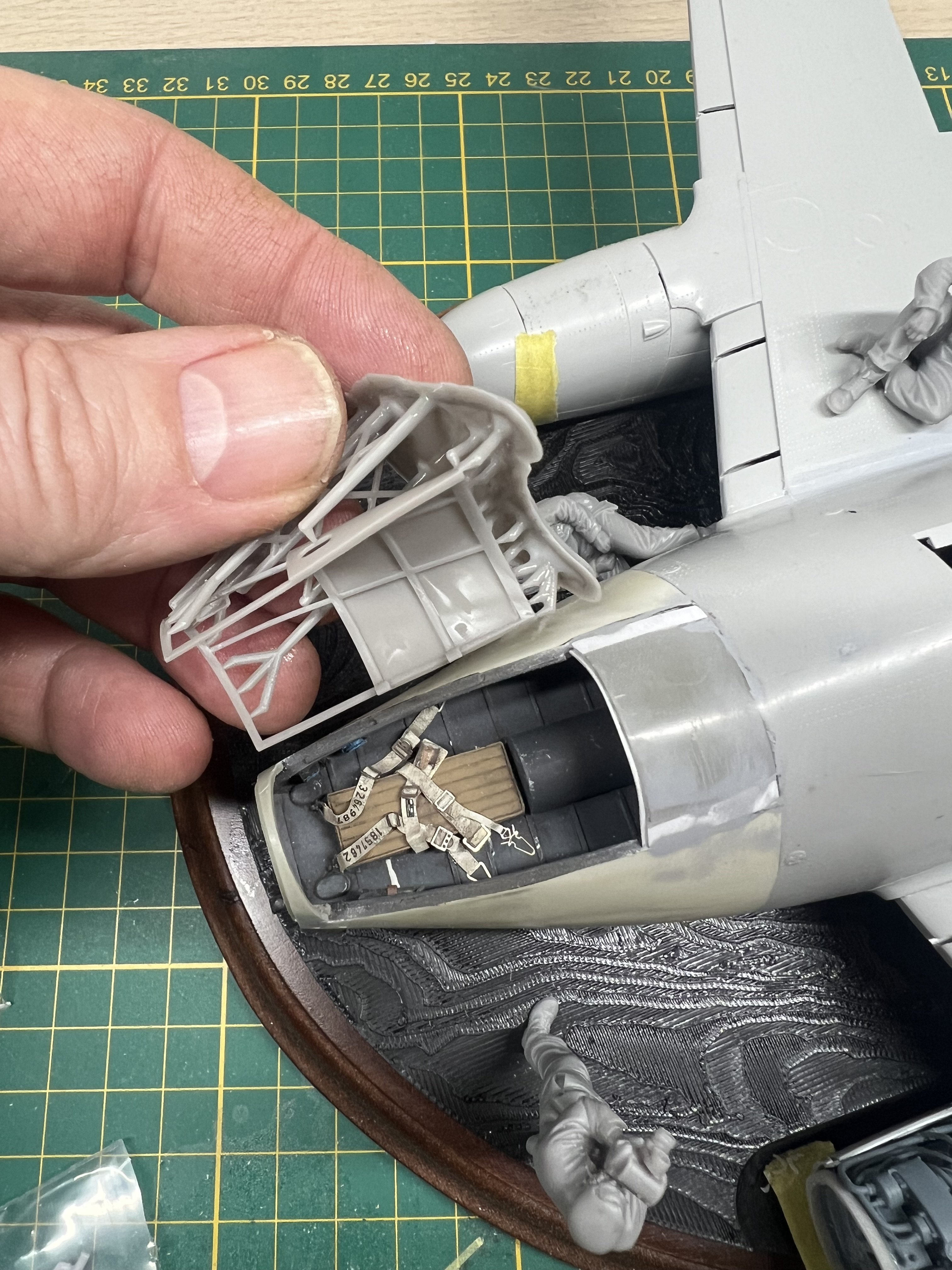
after getting really frustrated with the canopy 3d model for not being solid and therefor not printing, I re-drew the whole damn thing in a different way. I think the open access hatch gave access to the canopy lock. So one could open it from the outside. I'll fashion a similar kind of lock as was present in the pilot's canopy.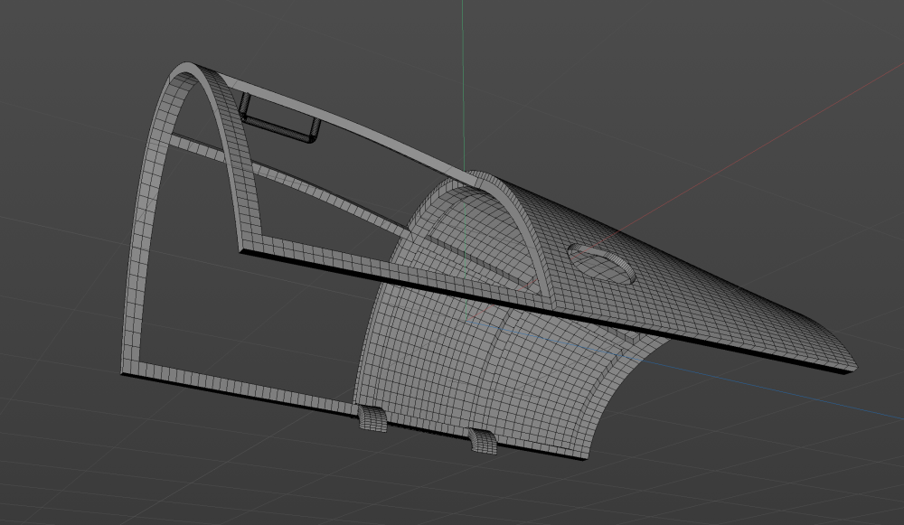
-
1/32 ME-262A-2a/U2
JeroenPeters replied to JeroenPeters's topic in LSM 1/35 and Larger Work In Progress
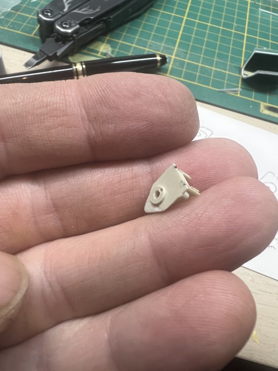
Something like this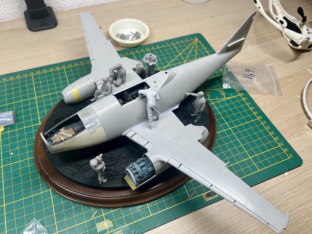
-
1/32 ME-262A-2a/U2
JeroenPeters replied to JeroenPeters's topic in LSM 1/35 and Larger Work In Progress
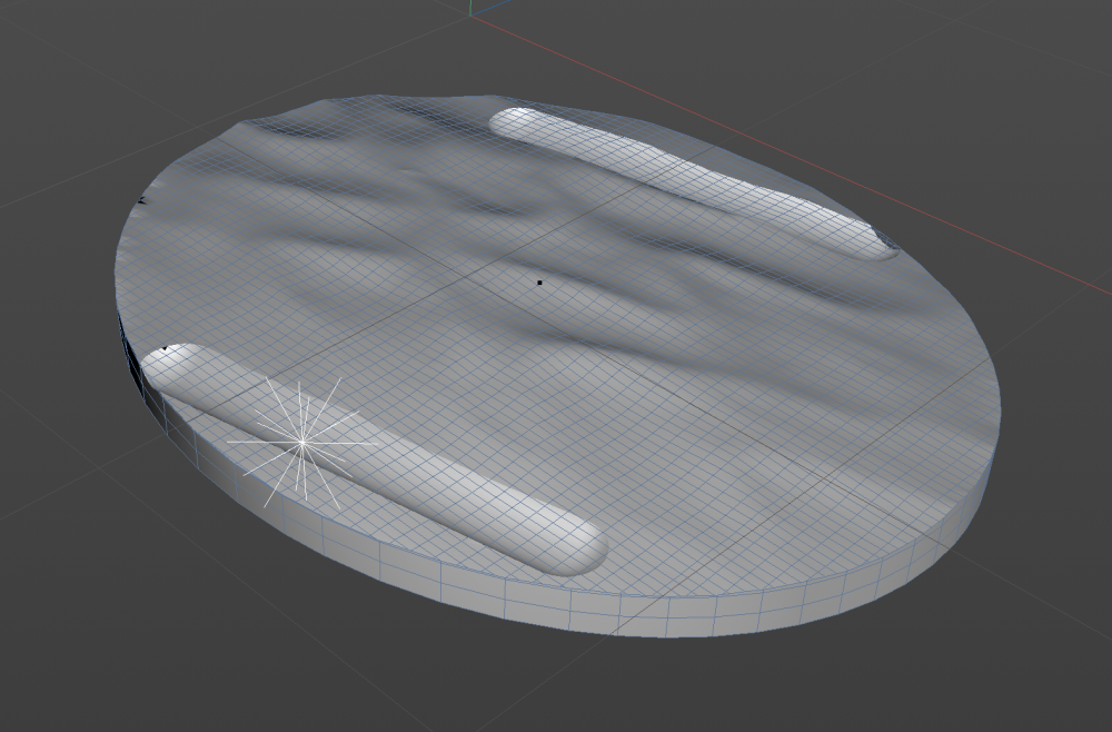
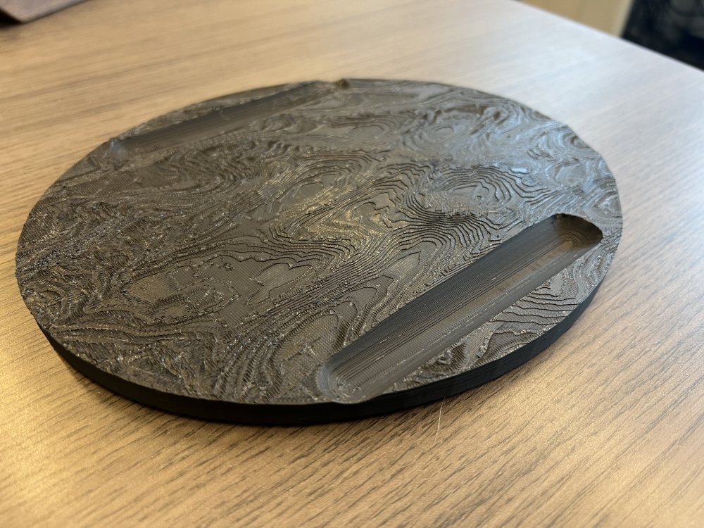
Base printed. This will be added as a starting point for grass and mudd.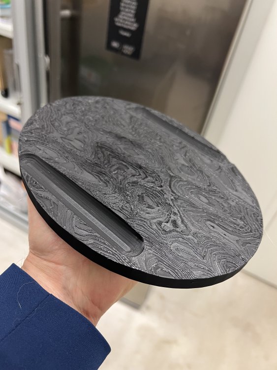
-
1/32 ME-262A-2a/U2
JeroenPeters replied to JeroenPeters's topic in LSM 1/35 and Larger Work In Progress
Started drawing the upper door of the bomb aimers postion in 3D. Tricky stuff.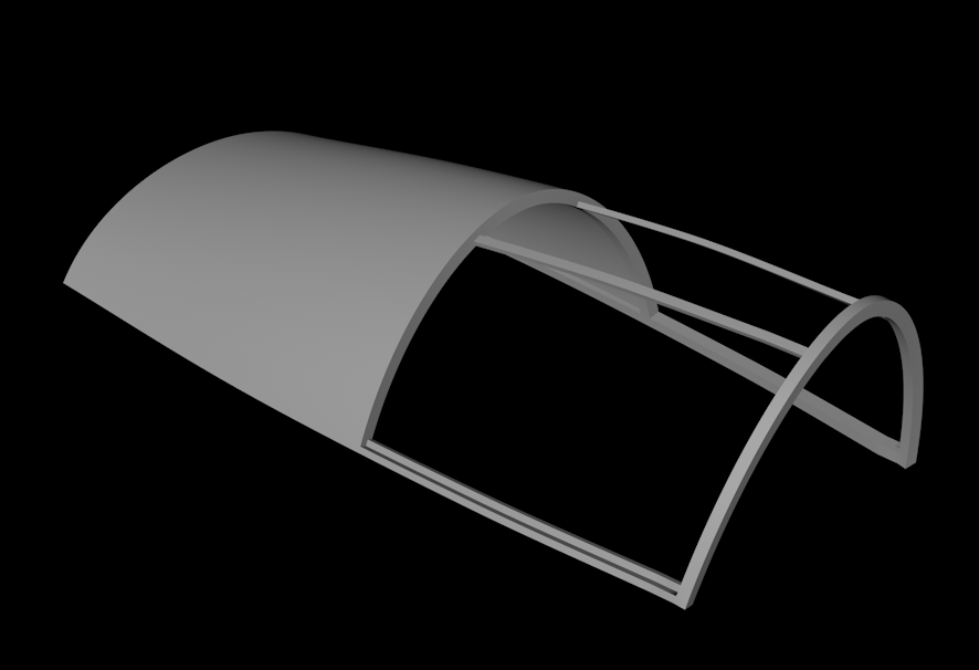
-
1/32 ME-262A-2a/U2
JeroenPeters replied to JeroenPeters's topic in LSM 1/35 and Larger Work In Progress
3D drew the terrain to fit the wood oval base. You can see the indentations for the engines. Further terrain will be added by... hand! Drawing this is literally 5 minutes of work.