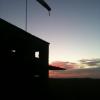
ThomasProbert Posted November 22, 2013 Author Posted November 22, 2013 Tom said he would try. Cees Sorry chaps... a full car meant that the Halifax didn't make the trip to Telford. Cees I think I must have just missed you on the 32SIG stand on numerous occasions which I was sorry about - it would have been good to catch up. Next year perhaps? Anyway, a little more to report on the Halifax... With the wings sorted it was time to start thinking about the tail. The stabilisers were the first job, and once removed from the backing sheet I had to thin them a fair bit to reduce the thickness as they were rather over scale in this department. I then removed the elevators as these will be scratch-built later, and scribed on the panel detail. I boxed in and modified the hinge line, as the kit has the elevators moulded the full length of the stabiliser but in reality this isn't the case and it follows a quite complex shape, as seen below. The kit's parts fit the plans rather well: Both stabilisers ready to be installed on the fuselage: As with the wings, I used wooden dowel as a spar: And both stabilisers were on and required a little filler in the joins to blend everything in nicely: When the sanding process was complete I turned my attentions to the fins themselves - in this instance the rectangular fins of the later MkII Series IA. I removed the rudders and boxed in the hinges: The rudders are about 3mm too long from top to bottom, but this is not something that overly concerns me and I've left them as they are. I then drilled holes in the inner surfaces and attached some spare sprue to provide a good strong join to the ends of the sabilisers: And then the fins were attached to the stabilisers and filed with some Milliput to strengthen the join: And now I have a structually complete Halifax. This (rather blurred - sorry!) picture shows her as she is now - sitting on the dining room table to give a sense of scale: The next task will most likely be detailing of the bomb-bay... where's the plastic card? Tom 2
Wingco57 Posted November 22, 2013 Posted November 22, 2013 Hi Tom, Yes, in fact I saw you chatting to someone at the 32SIG stand but didn't want to intrude. I would come back later but you were already gone. Next year we will certainly meet. The Halifax bombbay is certainly a challenge but a nice one. Looking forward to see your next installment. Cheers Cees 1
nmayhew Posted November 22, 2013 Posted November 22, 2013 Wow This is pretty hardcore stuff Most impressive
Administrators JayDee Posted November 22, 2013 Administrators Posted November 22, 2013 Loving this! This is pure, liquid inspiration.
olfogey Posted November 23, 2013 Posted November 23, 2013 WOW!!................... Jim J. -- "olfogey"
ThomasProbert Posted December 9, 2013 Author Posted December 9, 2013 More progress to report on the big Halifax... I've been concentrating on the bomb-bay of late and have scratched the main structure. Here's what I started with: a blank bay roof, which formed the main cabin floor above: It was then a case of cutting the individual longerons and cross members to the correct size from plastic card, making sure each part was the exact depth and size required - a rather tedious task! These parts were then added over a number of sessions: Here's the centre section coming together with it's deeper structure: Until finally everything was in place and the main structure was completed: I can assure you it won't be spot on in terms of accuracy, but it looks good enough to me! Tom 3
mgbgtv8steve Posted December 9, 2013 Posted December 9, 2013 Thomas - this is really an amazing piece of modelling! fantastic! Keep up the superb work! Regards, Steve S.
General Posted December 10, 2013 Posted December 10, 2013 The tried-and-tested 'TLAR' approach works well enough for me. Looking good so far, on a blank canvas of a vac kit! yiC Rossco
Wingco57 Posted December 10, 2013 Posted December 10, 2013 Tom, Looking great, did the bombay roof/floorpieces prove to be sturdy enough? Cees
ThomasProbert Posted December 10, 2013 Author Posted December 10, 2013 Tom, Looking great, did the bombay roof/floorpieces prove to be sturdy enough? Cees Yes they were excellent Cees... couldn't have done it better myself! If you want my fusleage parts that I didn't use you're welcome to them - they are still unstarted and on the sheet. Let me know if they'll be of use to you. Tom
Wingco57 Posted December 10, 2013 Posted December 10, 2013 Thanks for the offer Tom, Haha, that would be the same situation I started with a year ago. Will let you know. Cheers Cees
ThomasProbert Posted December 10, 2013 Author Posted December 10, 2013 I've begun thinking about the undercarriage on this build, and as there is none provided in the 'kit' it will all have to be made from scratch. Fun, fun, fun! I wanted to get the main wheels sorted first as it is vital to have the size of these to work with before I can begin making the undercarriage legs - this way I can ensure I build the legs around the wheels and use them for test fits etc. I raided my spares box and came across a set of vacformed main wheels which I didn't use on my B-29 build - these would prove to be a good starting point: However, when offered up to the plans there is an obvious problem... Yup... they are a little small, and also too narrow. I tackled the width issue by carefully measuring the plans and simply inserting some plastic card; this brought them up to the required width: [/url] I next had to increase the undersize diameter of the wheels and work out how to enlarge them. I did this by adding Milliput to the outer sections, and this had the advantage of creating the curved profile of the tyres, too. This is the first attempt after being smoothed over with water and before sanding has commenced, hence it looks pretty rough! I actually had to do this three times for each wheel to get them perfect (or as perfect as can be!) before I was happy with the result (see below under some primer.) I also filled in the hubs as they were somewhat lacking in detail! As you can see they are a far better size now and fit the plans far better. The hubs were tackled next, and I made these from plastic card, cut to shape with a circular cutter. Two different sizes of plastic disks were cut, and the cooling holes drilled. I lined the edges with Evergreen strip to ensure they were uniform in shape. There seemed to be a variation in hubs fitted to Halifaxes, and I must confess I have gone for the simplest version: Here are the wheels as they are now - primed up with just a few minor blemishes to fix: These were a lot of work but they've come out ok in the end. They should look passable with a coat of paint and a little weathering when the time comes... Tom 1
airscale Posted December 10, 2013 Posted December 10, 2013 amazing Tom - simply brilliant wheels are so hard to get right and these look spot on - ever thought about using resin casting as that way you only need to make one master? I thought it was all witchcraft, but then got a kit from Sylmasta for about £30 all in and never looked back - useful for all sorts of things including wheels as I found out.. love tuning in to see you work your magic Peter 1
Wingco57 Posted December 11, 2013 Posted December 11, 2013 Nice scratchbuilding Tom, You are not going to do the bevelled edges on the hubs then? These will hardly be seen anyway as soon as the massive undercarriage legs Are fitted. You are ahead of schedule now Cees
ThomasProbert Posted December 12, 2013 Author Posted December 12, 2013 Peter - resin casting is something I keep thinking about having a go at but have never got around to it. It's something I'll no doubt have a crack at one fday, and is sure to save work on builds like these. Cees - I may well do a little more the hubs at some point - I just wanted to get the size of the wheel right before embarking on the landing gear... Tom 1
Administrators JeroenPeters Posted December 12, 2013 Administrators Posted December 12, 2013 Great work Tom!! This is something that should be real easy to tackle if only you had detailed drawings in scale go the wheels. side, cross section, etc.. That way you could draw it in 3D and have it 3D printed...
Matt_ Posted December 12, 2013 Posted December 12, 2013 Tom Fab work.... I have only dabbled around the edges of vac forms and am really impressed at the momentum you maintain in your builds... Can't remember if you have any background in engineering or similar? I say that because the bit that I seem to fail on with vacs is getting everything lined up and square - your dowels for eg... getting them in place so wings just slide on is no mean feat... I must dig something out and finish it off.... Matt
ThomasProbert Posted December 13, 2013 Author Posted December 13, 2013 Great work Tom!! This is something that should be real easy to tackle if only you had detailed drawings in scale go the wheels. side, cross section, etc.. That way you could draw it in 3D and have it 3D printed... I am interested in 3D printing but will wait until it becomes more reasonably priced - it would certainly make jobs like this very much easier! Tom Fab work.... I have only dabbled around the edges of vac forms and am really impressed at the momentum you maintain in your builds... Can't remember if you have any background in engineering or similar? I say that because the bit that I seem to fail on with vacs is getting everything lined up and square - your dowels for eg... getting them in place so wings just slide on is no mean feat... I must dig something out and finish it off.... Matt Hi Matt, No engineering background at all - I'm a teacher! I have made a fair few vacforms over the years, and it is just a case of gaining experience with them and not being afraid to try new things - more often than not something will go wrong but that's how you learn... trial and error is the name of the game! Lots of dry fitting and trimming is always done before I commit to glueing any parts. I manage to keep motivated by having a normal injection moulded kit or two on the go at the same time (as well as this project I'm also building the HK B-17, Airfix's new 1/72nd Lancaster and a few airliners) and that keeps things fresh. When I've had enough of scratch-building and filling and sanding, out come the other easier builds and away goes the vac for a few days. Sometimes I won't touch it for weeks, and then the urge to get it out again means I'll get a little more done. I just view them as long-term projects, as builds such as this will often take close on to a year. Tom 1
Matt_ Posted December 13, 2013 Posted December 13, 2013 Ah... a teacher... so you'll also have a huge resource of patience... Well, I have a sort of started ID/Tigger Me 263 somewhere... maybe I should get it out again... Matt
imatt88 Posted December 14, 2013 Posted December 14, 2013 Tom, Excellent work! You are a master, indeed!
ThomasProbert Posted December 15, 2013 Author Posted December 15, 2013 Now I've got the wheels completed I have begun working on the main undercarriage legs. The MkI, MkIIs and MkIIIs all used the massive single-cast Messier undercarriage, as seen in this extract from the Granger plans: These would be reasonably straightforward to make as they're all flat sided and could be made without too much trouble from plastic card. I began by using 1.5mm card, and following the plans carefully cut out the front and back plates, as well as the side plates: The image above was taken before any refinement was done, and each of the four sides were offered up against each other to ensure all were identical. The font of the unit is angled backwards at the lower end, so this was bent to shape and then I began by slowly building up the shapes by adding the sides etc: I used slow drying liquid poly for this as it alids alignment and sets harder than CA glue when dry. Here is the left main casting complete. I used thinner card (0.5mm) for the curved wheel arch and the curved section on top of the unit, applying a little glue as I went and holding it in place. They then got a final trimming: I then added the mounting on top of the unit - on the real aircraft this pivot point is attached to the forward spar in the undercarriage bay - mine will do the same. I have also coated the joins where the plastic card meets with filler, which will be sanded after a god 24 hours drying time: I then made the lower part of the units such as the oleo struts and wheel mountings from spare sprue and Evergreen tubing - the bottoms of the main castings were then filled with Milliput for extra strength, as well as holding the oleos in place: When the filler has been sanded back I will be adding a lot more detail to the units, and will also begin to think about the retraction mechanisms. I've also had a play with the H2S scanner radome, as the aircraft I plan to build had this in place. I had a spare from my ID Models Lancaster build, so this had been trimmed and adapted slightly to fit the Halifax. I've rolled up 'worms' of Milliput to aid with the securing of this to the fuselage - the plastic is very thin and needs all the help it can get: I'm hoping to get the main undercarriage units finished off now, so I'll update you again when they are complete. Thanks for stopping by! Tom 4
Administrators JeroenPeters Posted December 15, 2013 Administrators Posted December 15, 2013 Damn Thomas, you make this look soooo simple! Very very nice.... 1
Wingco57 Posted December 16, 2013 Posted December 16, 2013 Tom, I love your legs. They need to be sturdy to support all that weight.Cees
ThomasProbert Posted December 16, 2013 Author Posted December 16, 2013 Tom, I love your legs. They need to be sturdy to support all that weight. Cees Are you saying I need to shed a few pounds Cees? The first task after yesterday's update was to sand the filler. Once this was done, I could check my handy work against the plans and to ensure everything was as it should be: Everything looked pretty good, so I could then start to add the additional details found on the legs. This was done with more plastic card and Evergreen strip, as well as a few parts from the spares box: Test fit, test fit, and test fit again is essential when scratch-building - here you can see the leg looks exactly as it should when mounted on the forward spar in the undercarriage bay: Now I was happy with the look and sit of the legs, it was time to add some primer: Here is a test fit of the main wheels: All in all, not bad, when you consider what I started with... nothing! The retraction mechanism will need to be done, but I feel the hardest part was the main casting of the Messier strut, and now that's out of the way it should be plain sailing from here... Tom 2

Recommended Posts
Create an account or sign in to comment
You need to be a member in order to leave a comment
Create an account
Sign up for a new account in our community. It's easy!
Register a new accountSign in
Already have an account? Sign in here.
Sign In Now