Wingco57
-
Posts
3,925 -
Joined
-
Last visited
Content Type
Profiles
Forums
Events
Gallery
Everything posted by Wingco57
-
RR Spey powered RAF Phantom conversion
Wingco57 replied to Wingco57's topic in LSM 1/35 and Larger Work In Progress
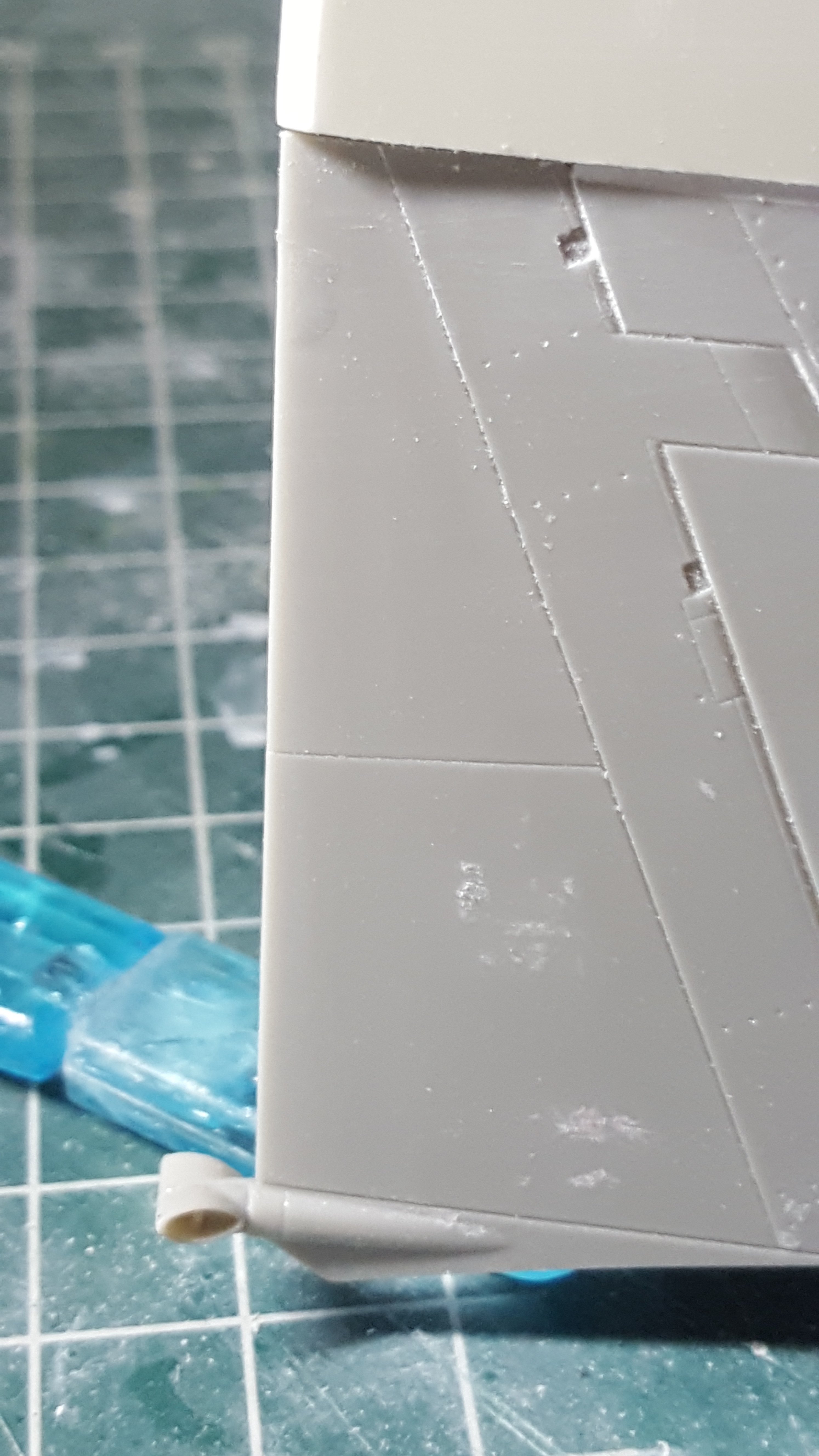
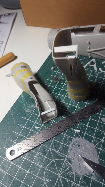
Ok. A small update. On the British Phantoms the fuel dump valves were shortened to fit the smaller aurcrafr carriers. The RAF ones had them too. Just cutting off the J-type valve, filing shorter and put the valves at a short dihedral stance. Quick and easy. Cees
- 414 replies
-
- 8
-

-
- conversion
- phantom
- (and 1 more)
-
RR Spey powered RAF Phantom conversion
Wingco57 replied to Wingco57's topic in LSM 1/35 and Larger Work In Progress
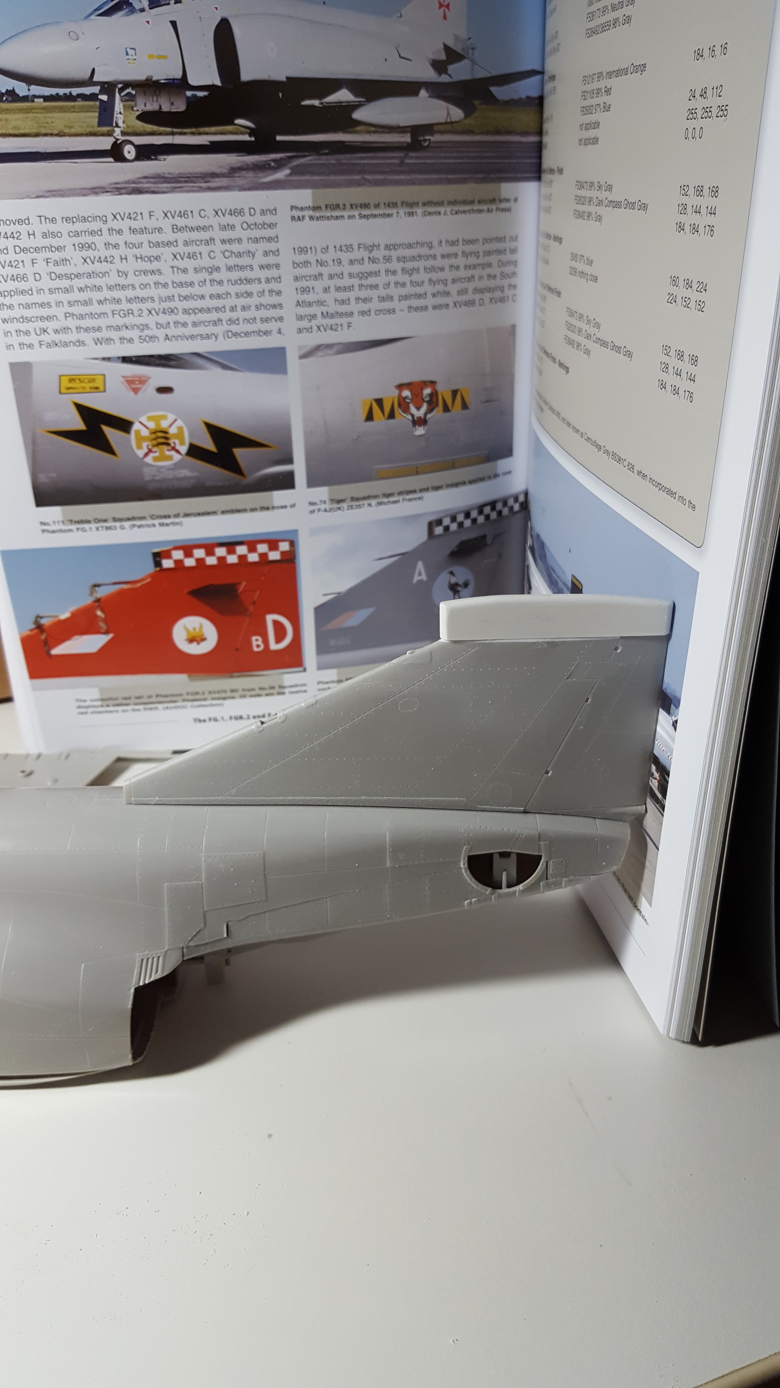
Thanks chaps. But it is no masterclass, just plodding along until something familiar emerges. Such as the basic shape of the fintop. Still needs details such as engraving of access panels and fairing it in with mr surfacer. The shorter fueldumping pipes to follow. Cees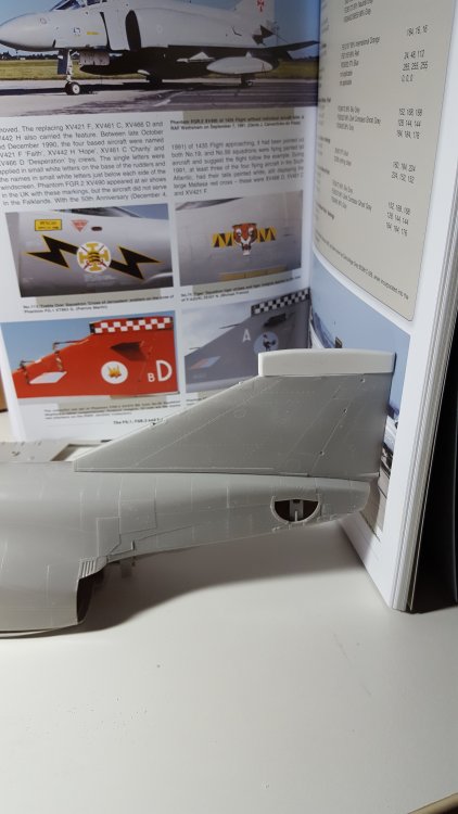
- 414 replies
-
- 8
-
-
- conversion
- phantom
- (and 1 more)
-
RR Spey powered RAF Phantom conversion
Wingco57 replied to Wingco57's topic in LSM 1/35 and Larger Work In Progress
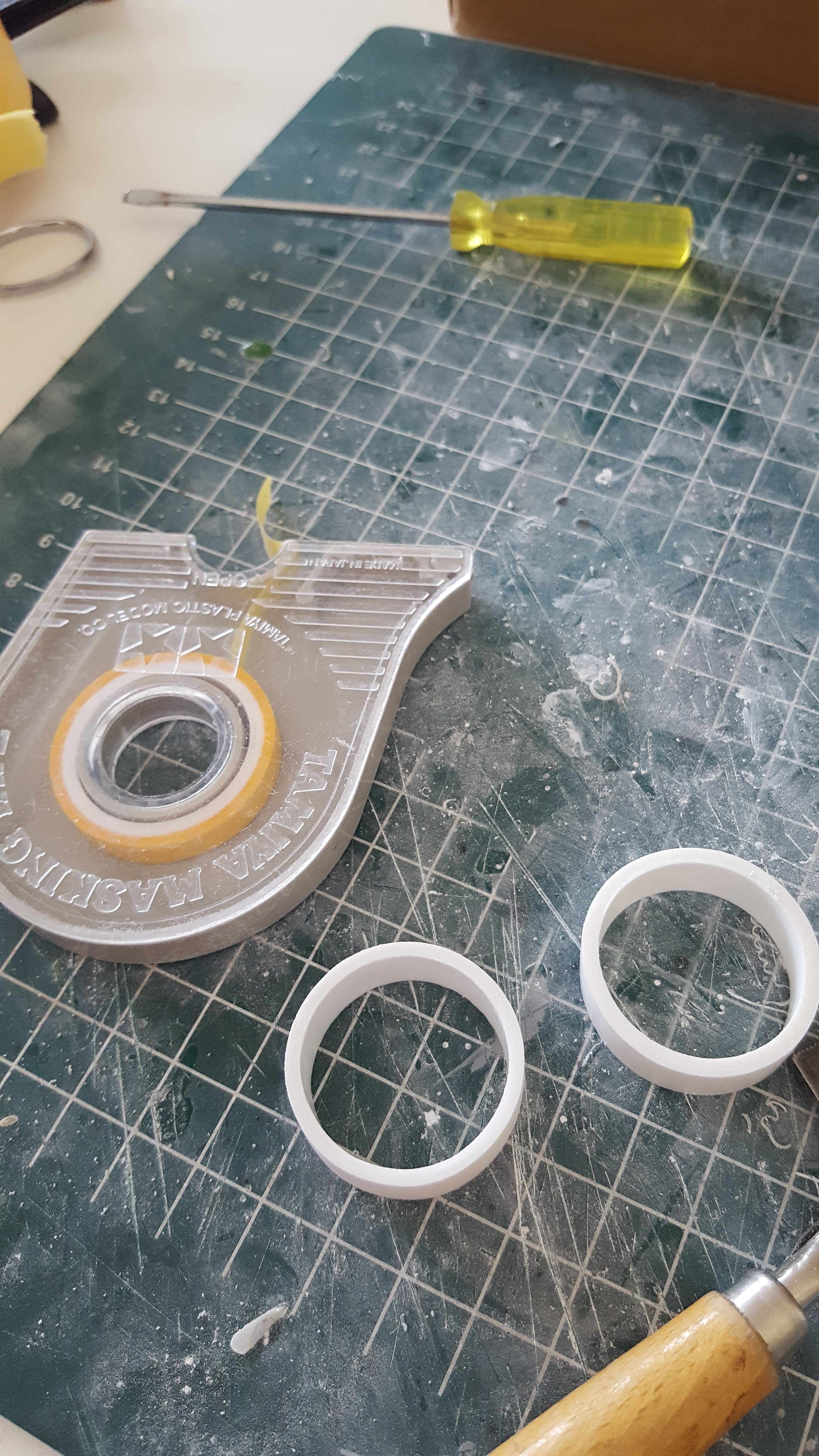
By your command....... The plastic inner rings of the Revell tape rolls are 3 cm in diameter and perfect for the exhaust cans although they need to 1.5 cm long but that is no problem. We come to that later. First to see how to make the deeper rear section. Having Frank's article doesn't mean it's easy. Cees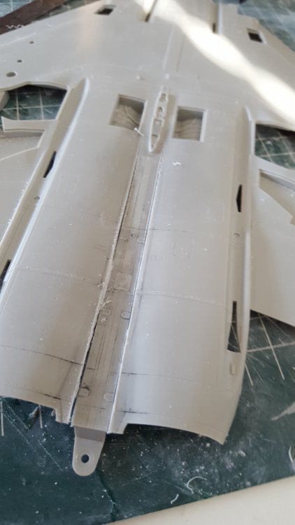

- 414 replies
-
- 8
-
-
- conversion
- phantom
- (and 1 more)
-
RR Spey powered RAF Phantom conversion
Wingco57 replied to Wingco57's topic in LSM 1/35 and Larger Work In Progress
Gaz, it is supposed to look very much different from the US Phantoms.- 414 replies
-
- 3
-
-
- conversion
- phantom
- (and 1 more)
-
RR Spey powered RAF Phantom conversion
Wingco57 replied to Wingco57's topic in LSM 1/35 and Larger Work In Progress
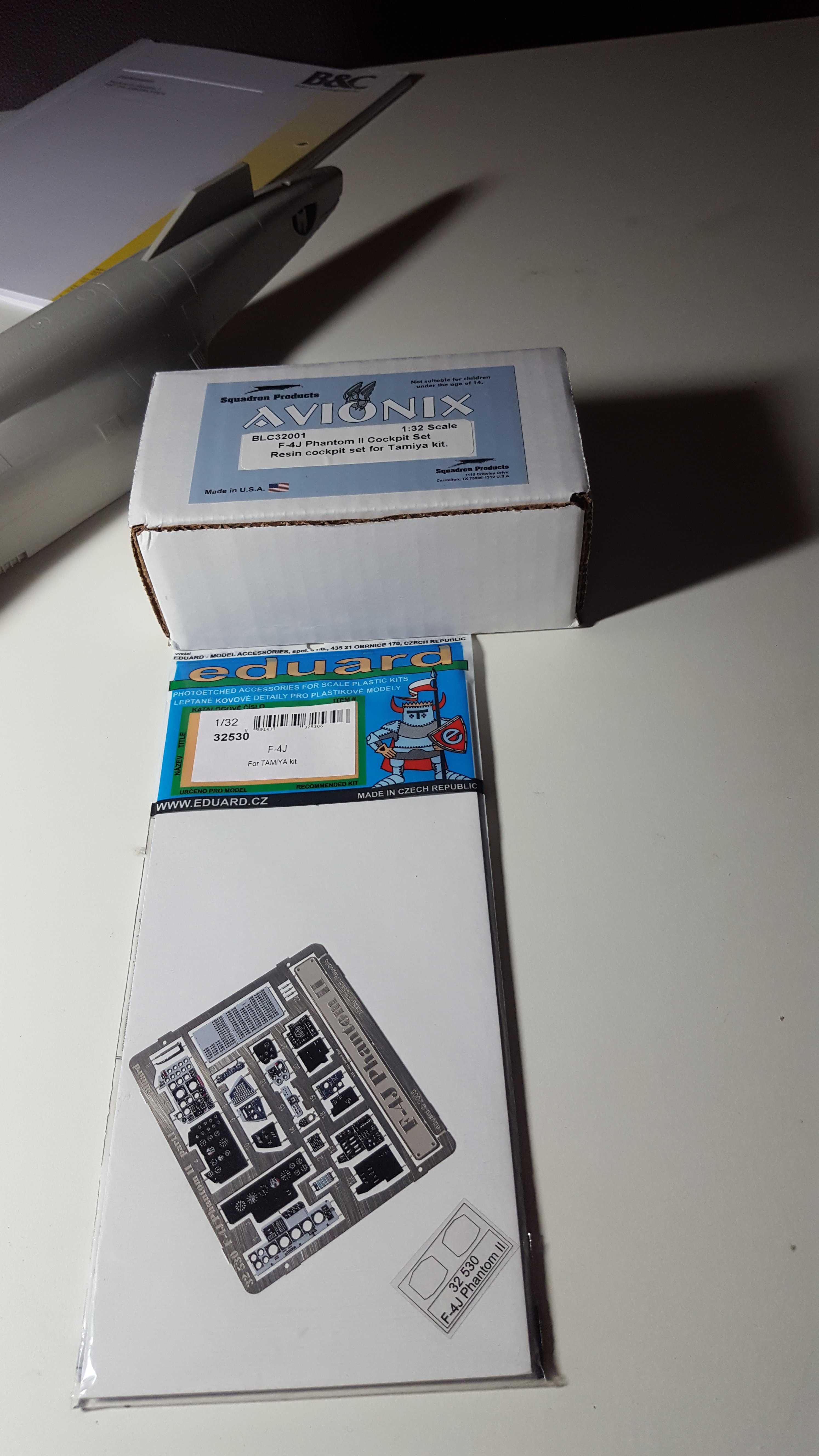
Got me some goodies for the cockpit. And the intakes have been cemented in place. I feel a sanding and Milliput session coming up. Cees

- 414 replies
-
- 9
-
-
- conversion
- phantom
- (and 1 more)
-
dn models DN Models Lancaster Paint Mask set (Numbers and Insignia)
Wingco57 replied to JeroenPeters's topic in Aircraft Reviews
I'm tempted. -
RR Spey powered RAF Phantom conversion
Wingco57 replied to Wingco57's topic in LSM 1/35 and Larger Work In Progress
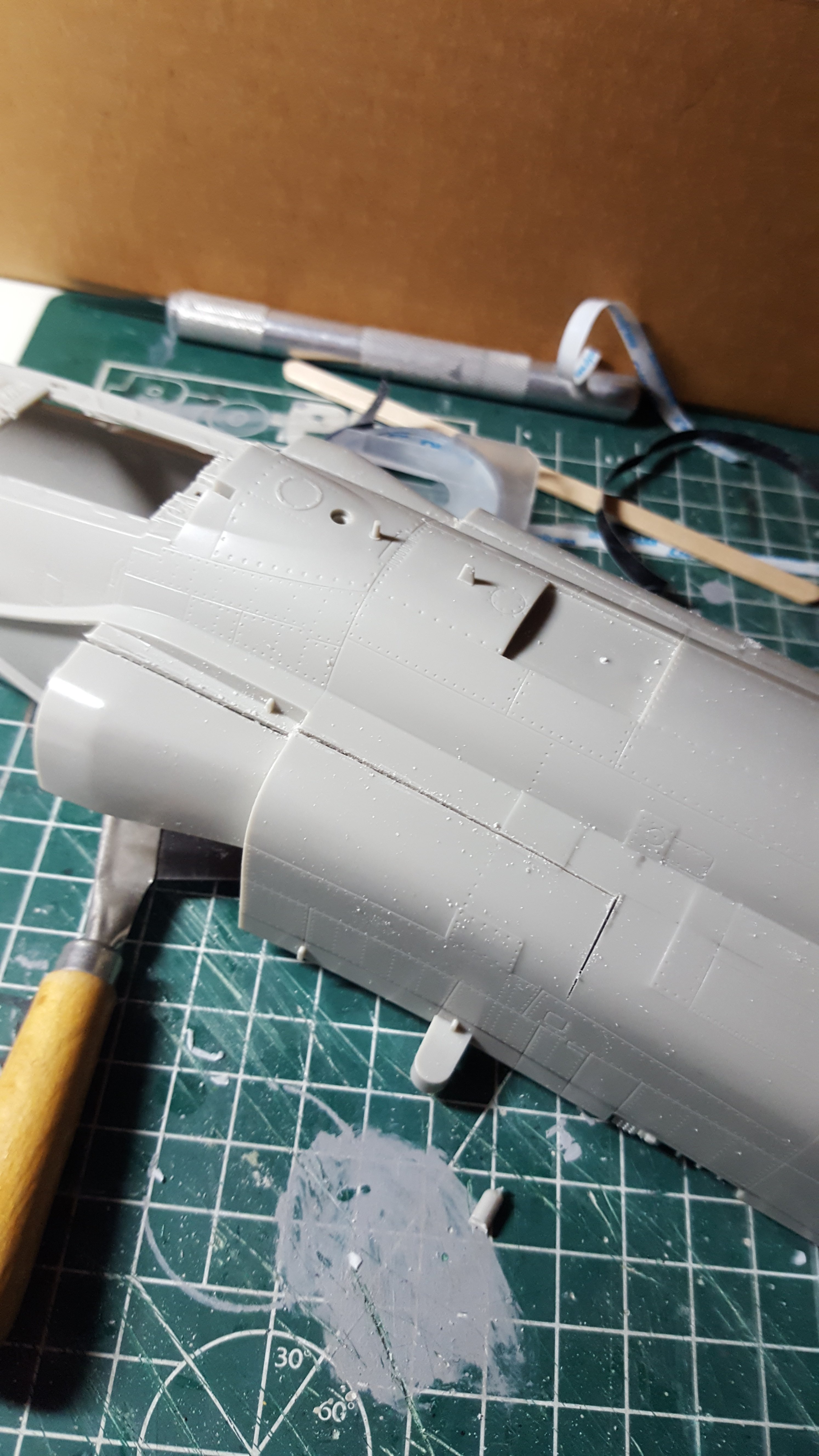
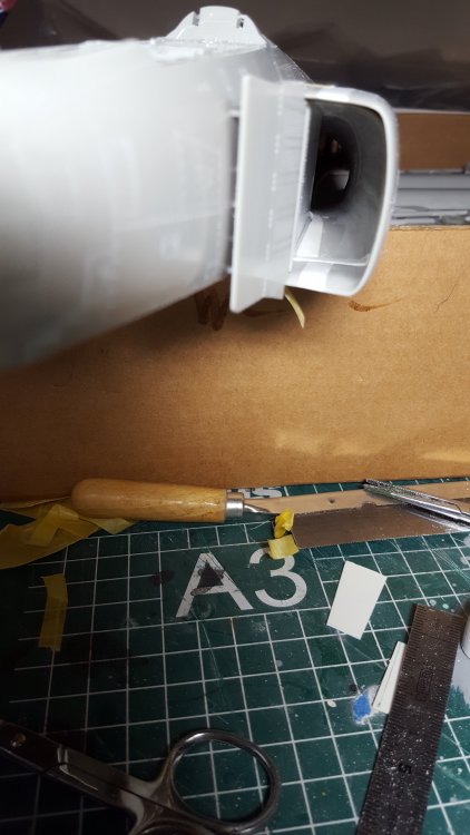
It takes a lot of cutting, adding plastic and sanding to get a reasonable fit. But this is as good as it gets. Milliput will be used to smooth things out. Hope you like. Cheers Cees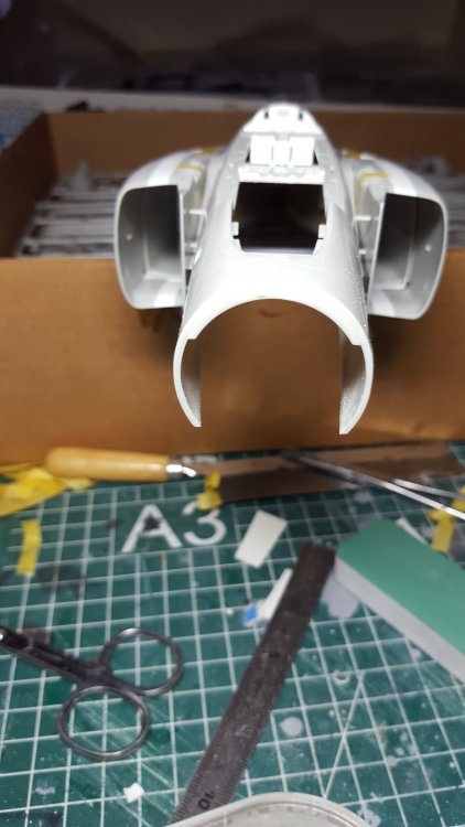
- 414 replies
-
- 12
-
-
- conversion
- phantom
- (and 1 more)
-
RR Spey powered RAF Phantom conversion
Wingco57 replied to Wingco57's topic in LSM 1/35 and Larger Work In Progress
Getting there. Cees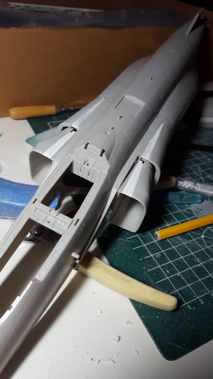
- 414 replies
-
- 9
-
-
- conversion
- phantom
- (and 1 more)
-
Takom 1/35 V2 Rocket
Wingco57 replied to JeroenPeters's topic in LSM 1/35 and Larger Work In Progress
How about oilcanning on the figure or is that too overstated? Cees -
The Force is strong with this one...
Wingco57 replied to Bill_S's topic in LSM 1/35 and Larger Work In Progress
The force is extremely strong in you. Me likey! Cees -
What is on your bench right now ? Share a picture :)
Wingco57 replied to Martinnfb's topic in Modelling Discussion
It's difficult to stay on topic eh? What a cat-astrophy! Cees -
RR Spey powered RAF Phantom conversion
Wingco57 replied to Wingco57's topic in LSM 1/35 and Larger Work In Progress
That makes 2 of us Anthony Cees- 414 replies
-
- 4
-
-
- conversion
- phantom
- (and 1 more)
-
Takom 1/35 V2 Rocket
Wingco57 replied to JeroenPeters's topic in LSM 1/35 and Larger Work In Progress
You are right Jeroen, compared to that figure the rocket is huge. Cees -
RR Spey powered RAF Phantom conversion
Wingco57 replied to Wingco57's topic in LSM 1/35 and Larger Work In Progress
Hang on...this might actually work. Cees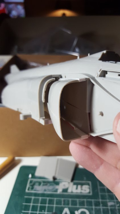
- 414 replies
-
- 7
-
-
- conversion
- phantom
- (and 1 more)
-
Short Sunderland MkII
Wingco57 replied to ThomasProbert's topic in LSM 1/35 and Larger Work In Progress
Very nice tom. Cees -
RR Spey powered RAF Phantom conversion
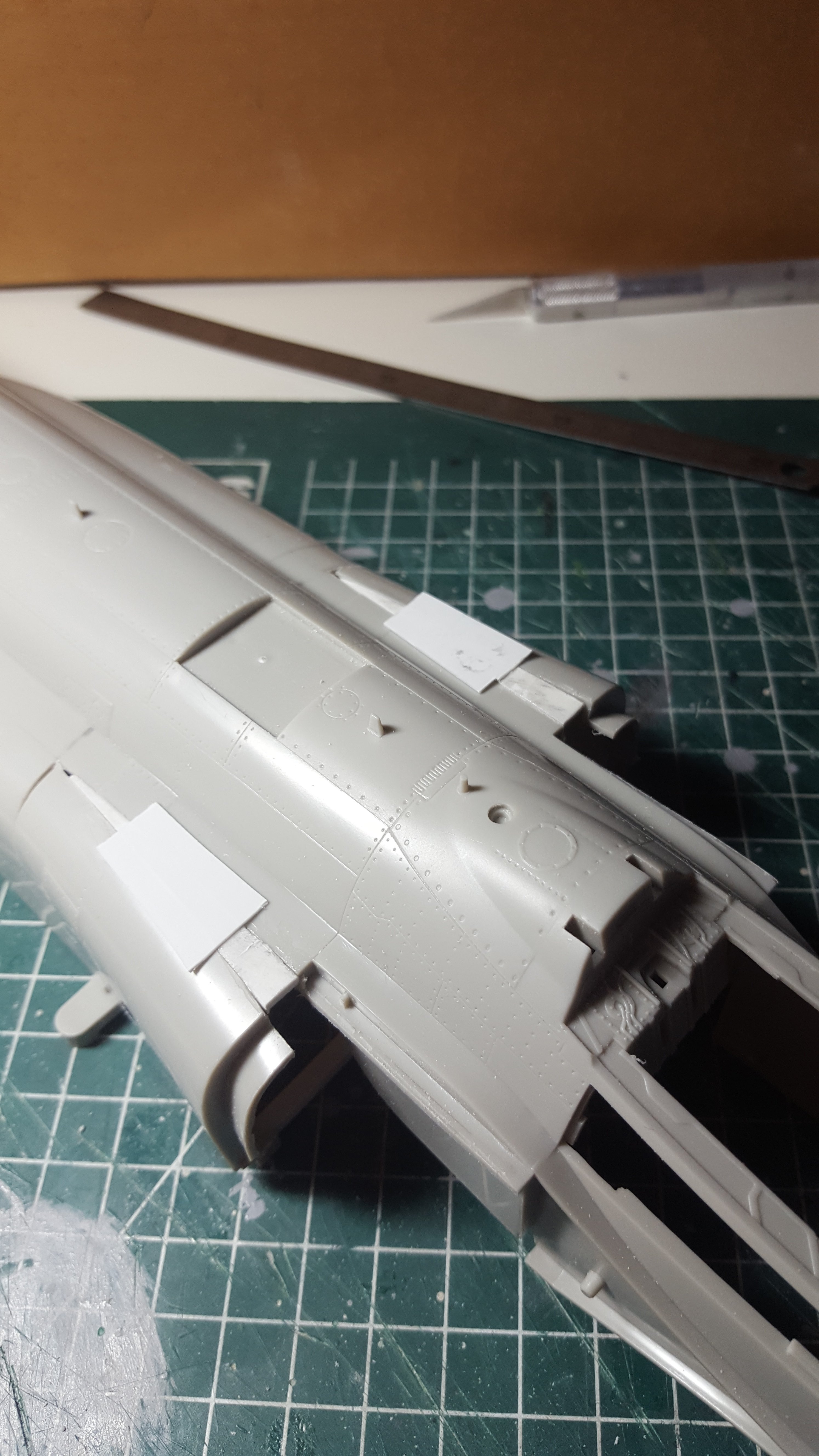
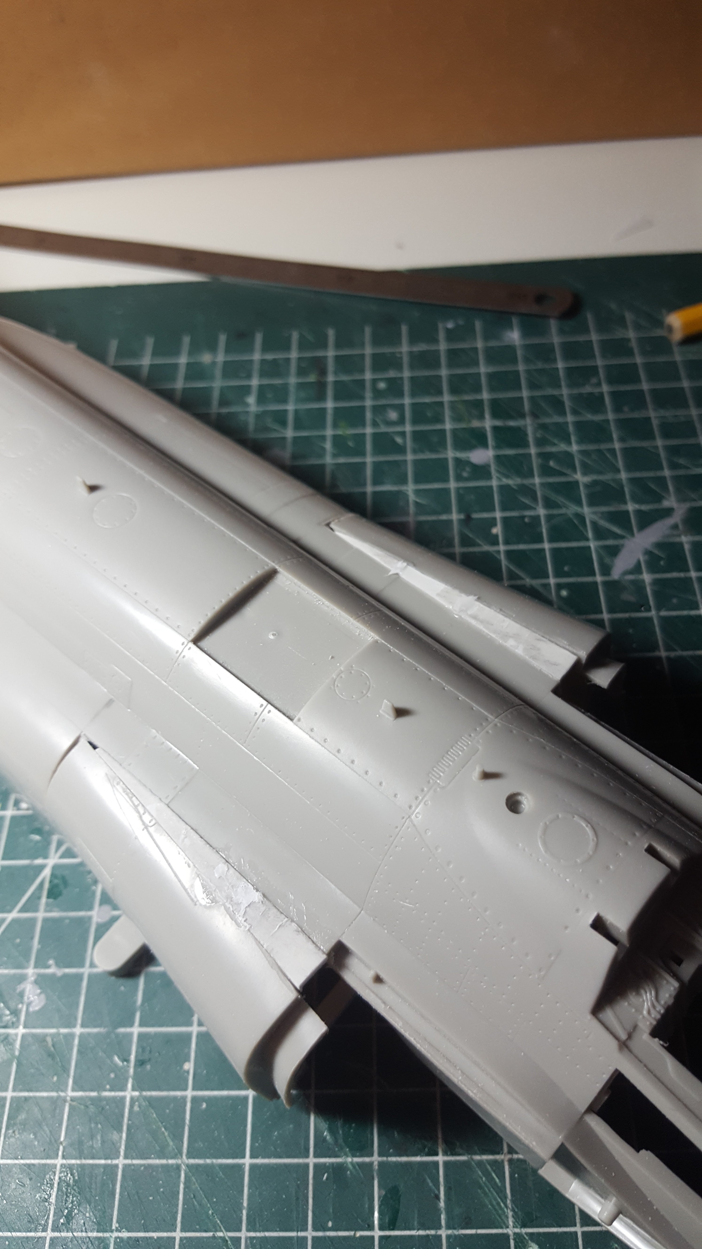
Wingco57 replied to Wingco57's topic in LSM 1/35 and Larger Work In Progress
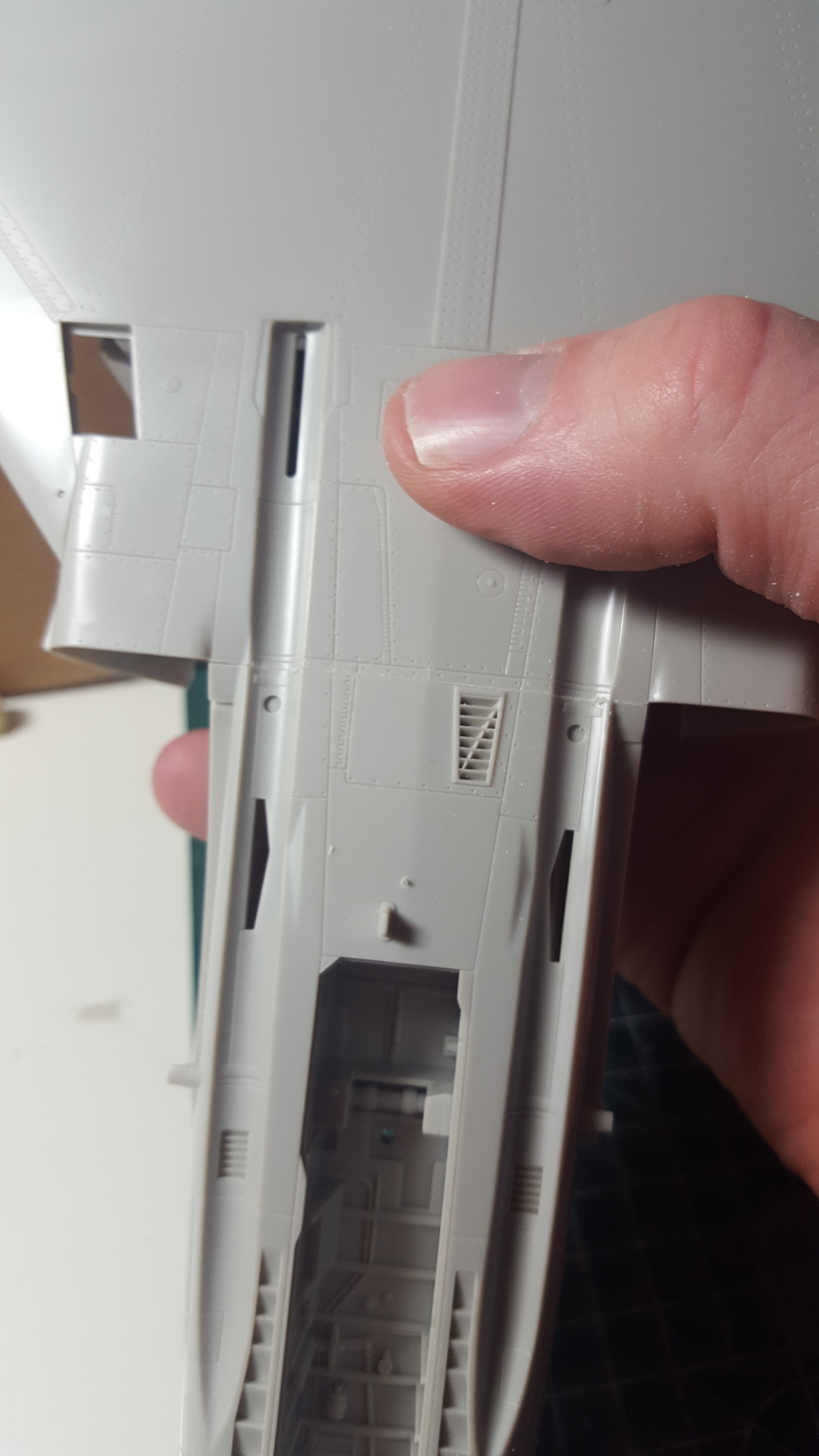
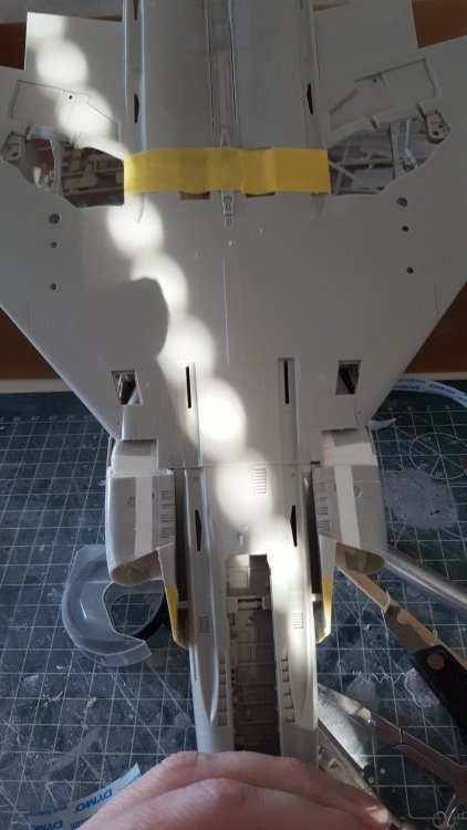
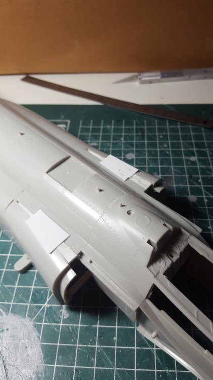
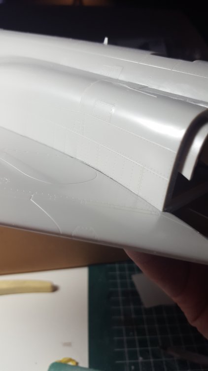
Some more work done. The flaps were sawed in to enable the underside to be bent downwards later. Further work on the intake trunks. The top fillerpieces have been glued in. The flat pieces have a purpose and prevent the filler pieces from sitting too low. You see them cut away later. My take on the inner intake pieces. I assembled the cut off pieces and inserted a piece of plasticard in the join forcing it outwards. Later the missing pieces will be added from card and the insides smoothed with miliput. At least that is the plan. If it fails I will use the easy way....intake covers. Cheers Cees

- 414 replies
-
- 8
-
-
- conversion
- phantom
- (and 1 more)
-
RR Spey powered RAF Phantom conversion
Wingco57 replied to Wingco57's topic in LSM 1/35 and Larger Work In Progress
Haha, nobody can blame me for not making the most accurate FGR then. I like that. Cees- 414 replies
-
- 1
-
-
- conversion
- phantom
- (and 1 more)
-
Takom 1/35 V2 Rocket
Wingco57 replied to JeroenPeters's topic in LSM 1/35 and Larger Work In Progress
Very nice Jeroen, I may warn you. Once you start scratchbuilding there is no way back! Cees -
1/32 Lancaster build and improvements
Wingco57 replied to NigelR32's topic in LSM 1/35 and Larger Work In Progress
I agree, better to check wartime period photo's. I remember seeing some AVRO drawings that showed the table to be of wooden construction. The Mk X (Canadian) differed in many details, the table being probable one of them. Cees -
RR Spey powered RAF Phantom conversion
Wingco57 replied to Wingco57's topic in LSM 1/35 and Larger Work In Progress
Thanks chaps for the info. I think a lot of people are not aware of the many changes regarding the Spey-powered Phantoms. By the way, can anyone point me into the direction of some usable scale drawings? Cees- 414 replies
-
- 1
-
-
- conversion
- phantom
- (and 1 more)
-
RR Spey powered RAF Phantom conversion
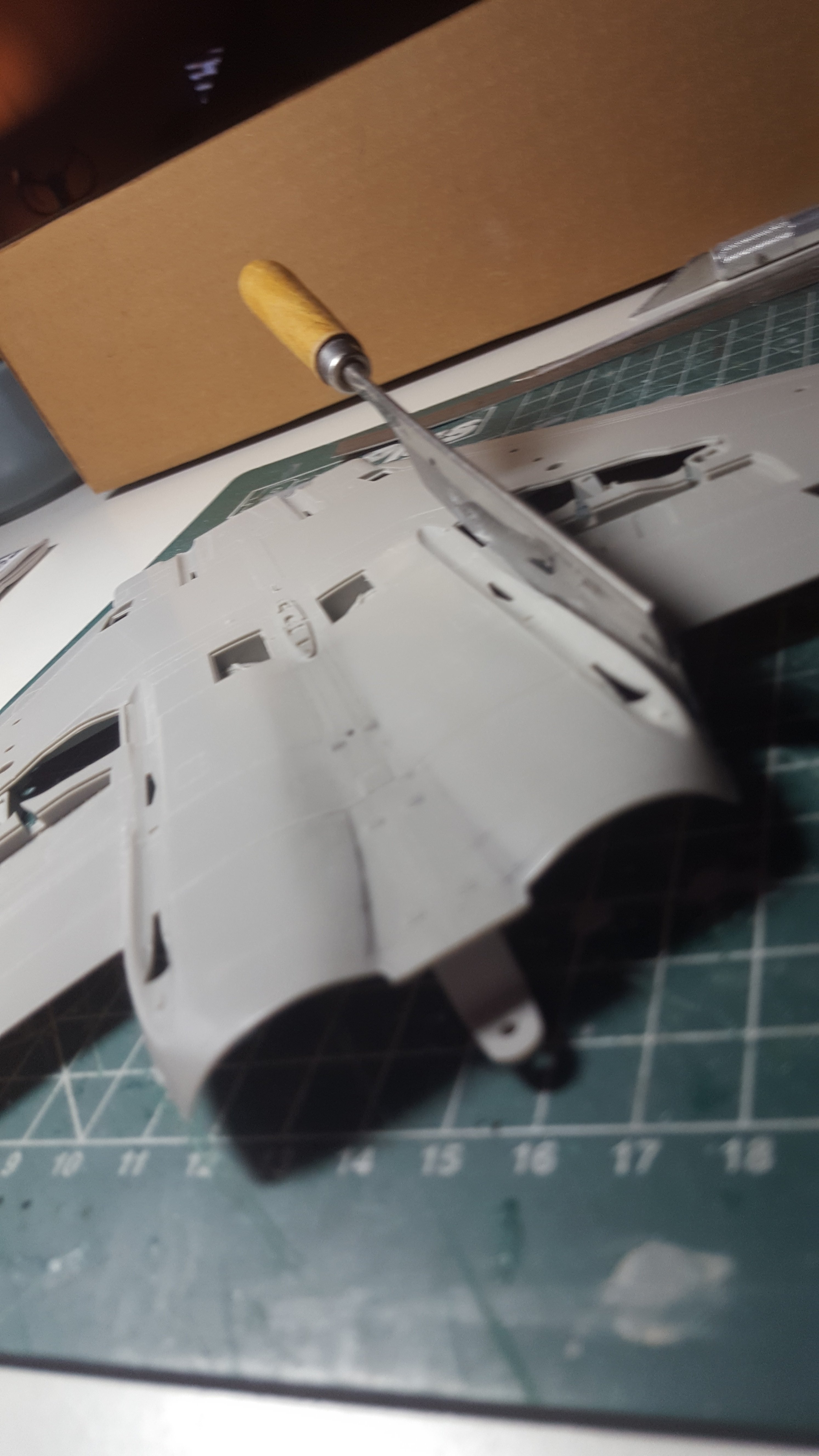
Wingco57 replied to Wingco57's topic in LSM 1/35 and Larger Work In Progress
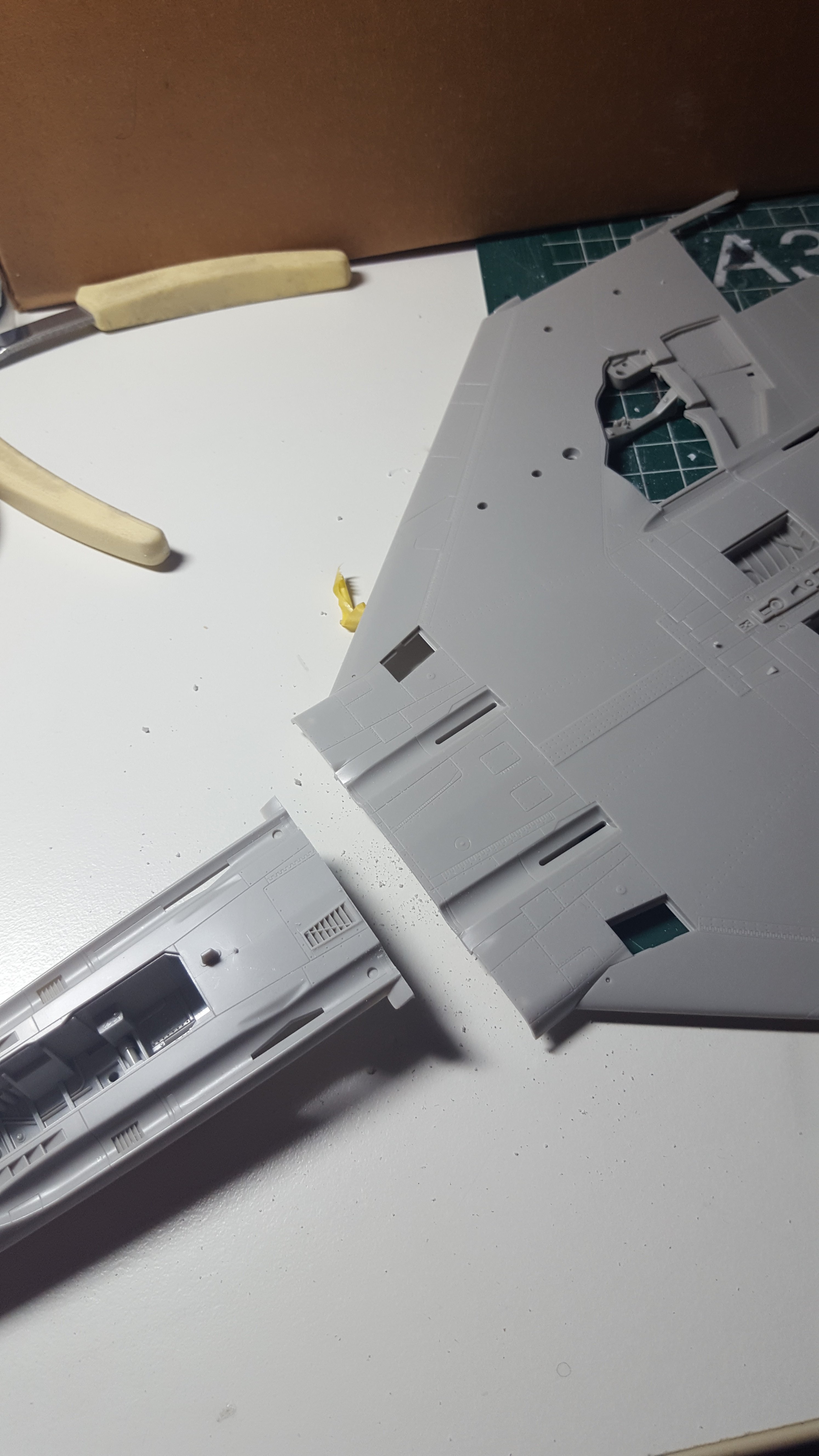
Thanks for thinking of me Carl. Some more sawing was in order. I seperated the front of the bottomsection in order to fit the cockpit after the wing and fuselage have been assembled. In that way the cockpit will not be damaged during the cutting and sanding proce and the parts can be cemented together. I made a straight cut across and the joint looks to be perfect. Also very pleased with the wing to fuselage join where the widened section fits nicely on top. That will save some filling. Very pleased with the progress so far. Cees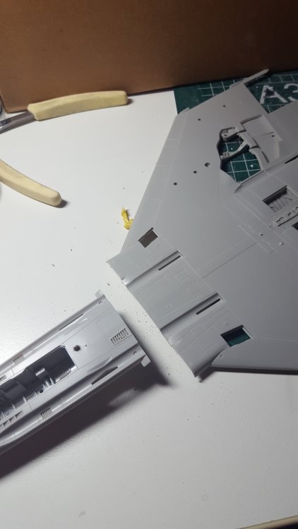
- 414 replies
-
- 6
-
-
- conversion
- phantom
- (and 1 more)
-
RR Spey powered RAF Phantom conversion
Wingco57 replied to Wingco57's topic in LSM 1/35 and Larger Work In Progress
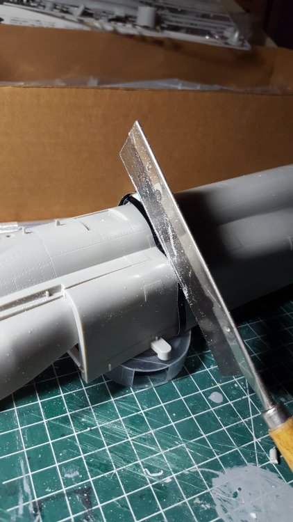
Thanks Nige, That (razor)saw I have since 1988 and it has made many casualties over the years. It still is quite sharp. If a kit is released before I finish my conversion I don't care and would buy it anyway as there are plenty of interesting liveries to model. Cees- 414 replies
-
- 3
-
-
- conversion
- phantom
- (and 1 more)
-
HK Models 1/32 Lancaster Hints, Tweaks and Tips,
Wingco57 replied to NigelR32's topic in Modelling Discussion
I would suggest the shrouds fitted in front of the ailerons would give the wing the required height to enable the tips to fit well. If you don't fit the shouds the ends could sag and impair the fit of the tips. Purely theoretically speaking mind you. Cees -
RR Spey powered RAF Phantom conversion
Wingco57 replied to Wingco57's topic in LSM 1/35 and Larger Work In Progress
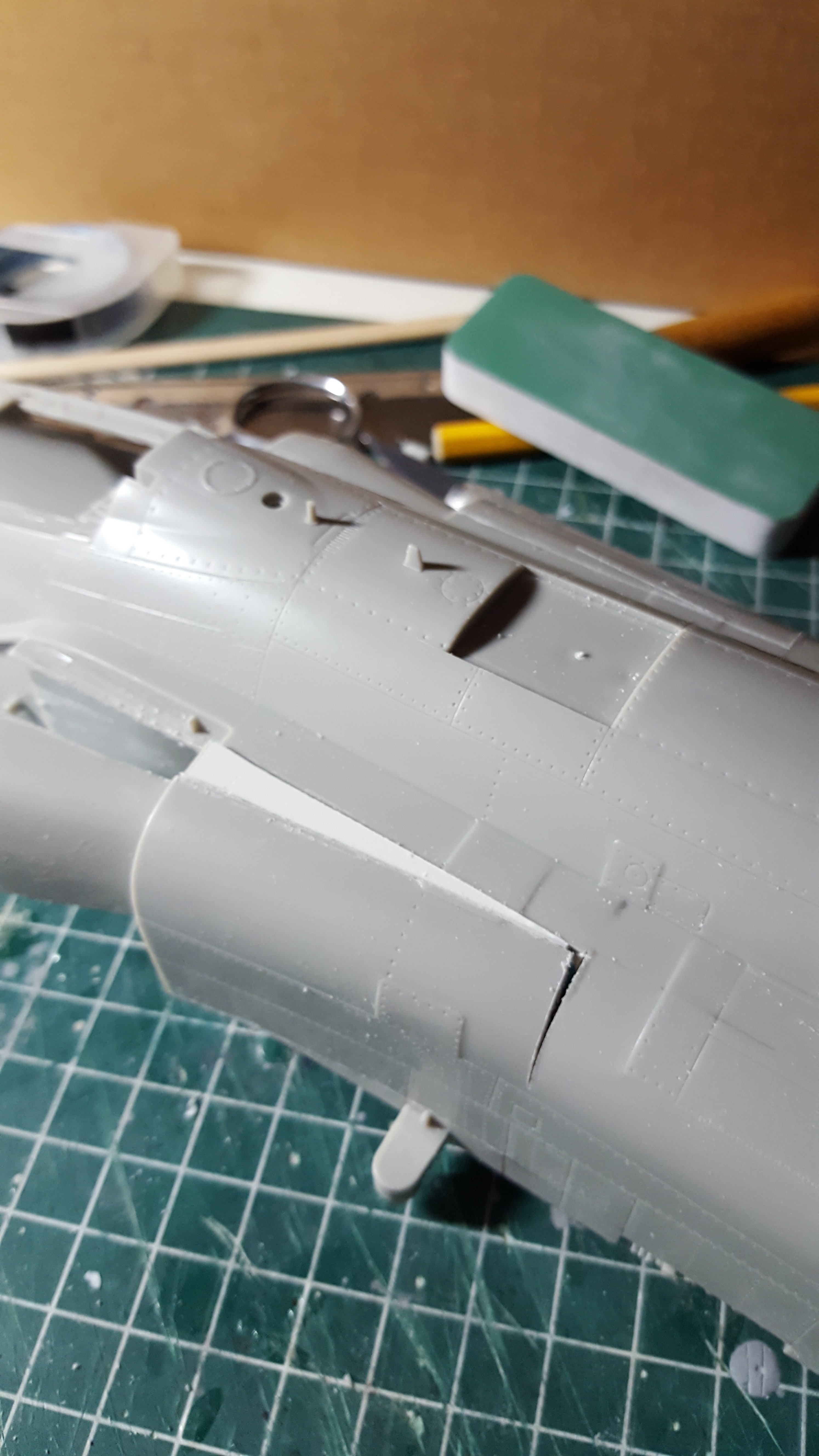
Thanks, I noticed and I plan to build up that "bump" with Miliput. The top has to be smoothed out anyway after the intakes were widened because of the piece of plasticard that was inserted the smooth flow of the sides was interrupted. Cees- 414 replies
-
- 3
-
-
- conversion
- phantom
- (and 1 more)
-
RR Spey powered RAF Phantom conversion
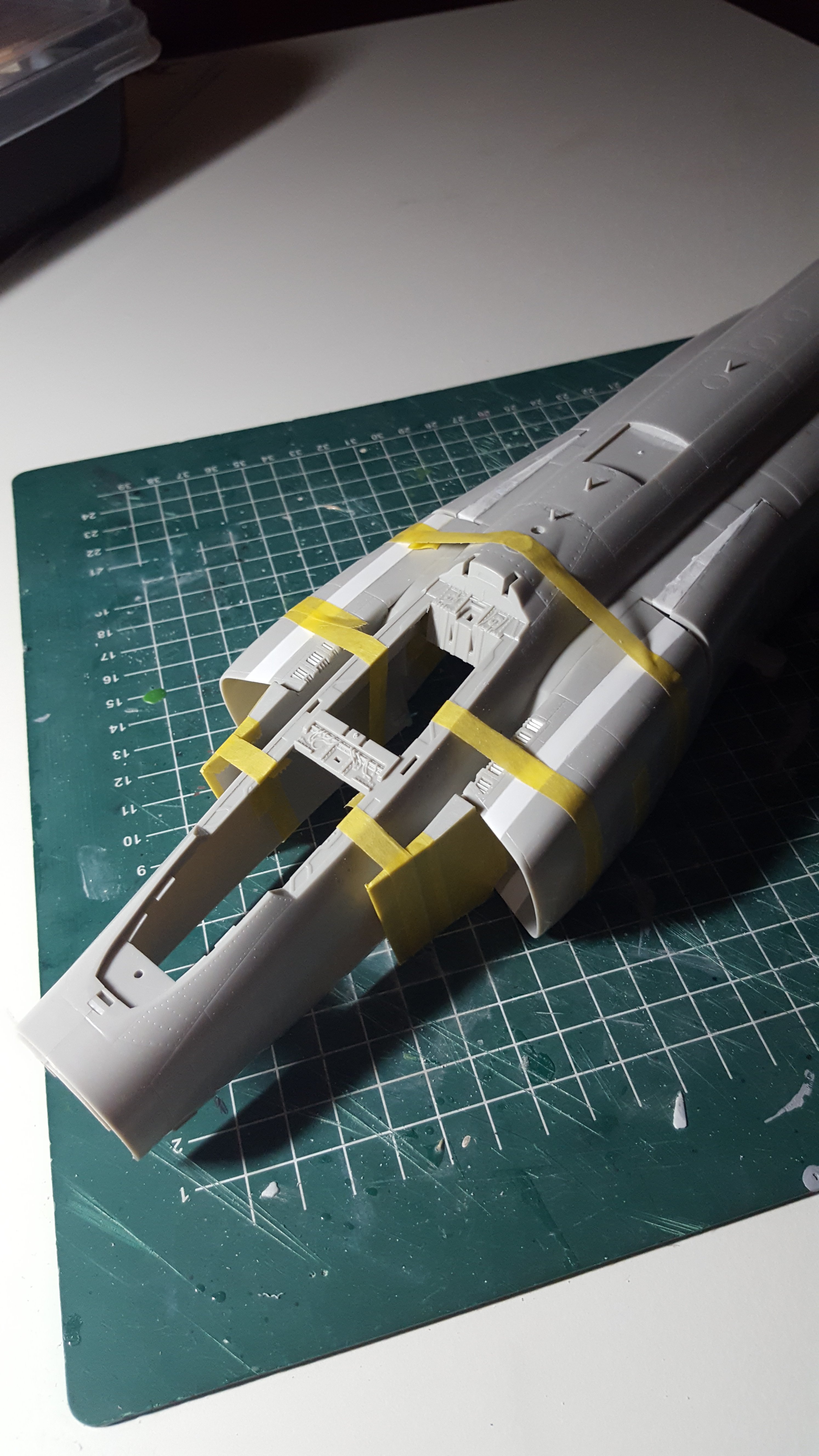
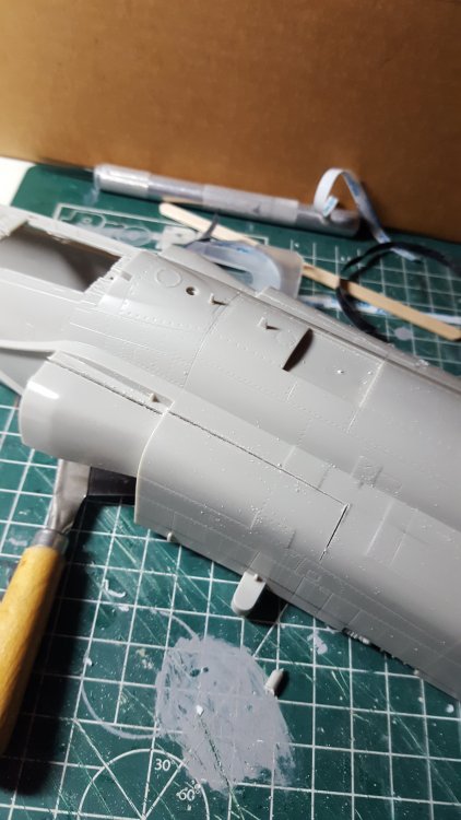
Wingco57 replied to Wingco57's topic in LSM 1/35 and Larger Work In Progress
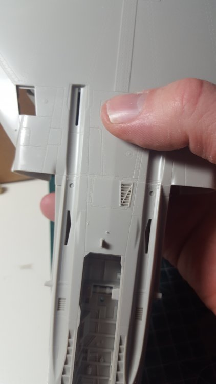
Well...as promised the butchery has begun. Cuts were made to enable the intake fairings to spread out and connect to the widened intakes. Pieces of wedge shaped plasticard fill the gaps. So far so good. Cees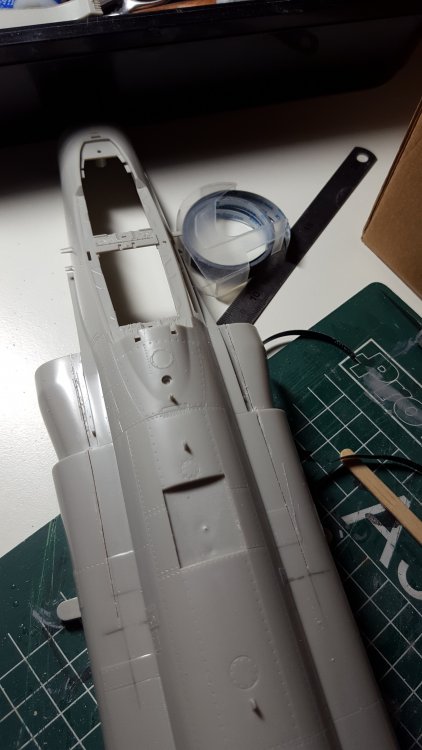


- 414 replies
-
- 10
-
-
- conversion
- phantom
- (and 1 more)