

GazzaS
-
Posts
6,396 -
Joined
-
Last visited
Content Type
Profiles
Forums
Events
Gallery
Posts posted by GazzaS
-
-
What a stunning result, Kai! Absolutely perfect painting!
-
 4
4
-
-
8 minutes ago, Peterpools said:
Gaz
Incredible work - the rocket launchers look the part for sure and I can easily see and appreciate the amount of work needed to build and install them.
Keep 'em comin
Peter
Thank you, Peter. I can assure you... I won't be rushing to make more.
-
3
-
-
9 minutes ago, DocRob said:
Nice work on the rocket tubes, Gaz. I tried to look for correct placement angles on the pics, Eduard's manual and have to say, it's really hard to interpret it correctly. In the Eduard manual, it seems like the front rods are angled forwards, where the back rods are more or less 90 degrees angled. On their CAD pictures all struts seem aligned at 90 degrees. The photos don't make it easier, so in the end, I think you got it right and the most important aspect, the upward angle of the tube looks convincing.
I love metal works in modelling, I just can not hide my metal engineer background") .
.
Cheers Rob
Thank you, Rob. Everything is still flexible. The brass - aluminum joint isn't strong and it just seems like the glue won't make a firm joint. I think the best ting would be to use brass tube if you can find it in 8mm.
I got my angles, lengths, and drilling positions from other pics supplied in this thread.
-
2
-
-
37 minutes ago, Kaireckstadt said:
Your rocket-tubes and the attachment parts look great Gary.
I don’t think that the angles of the brass-rods will be visible anyway when finished. Models with these weapons are seldom seen! That’s why I like it so much!When I build mine I will drill holes in the wings and the tubes. Hope this makes alignment easier. But that’s not possible with the metal tubes.
That’s lots of fiddly work and the anchors look awesome!
Curious how they look like painted and attached.
Thank you, Kai. Do you guys think I didn't drill holes in the tubes? I did... other wise it would be impossible to assemble. I set my Dremel to 30K RPMs and used my Dremel drill press. I was surprised how quickly the drill bit in.
I'll prime them this week, most likely.
-
1
-
 1
1
-
-
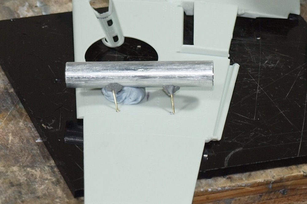
Heh... here I am again!
Well... all of my modelling time this weekend was spent on two small assemblies.
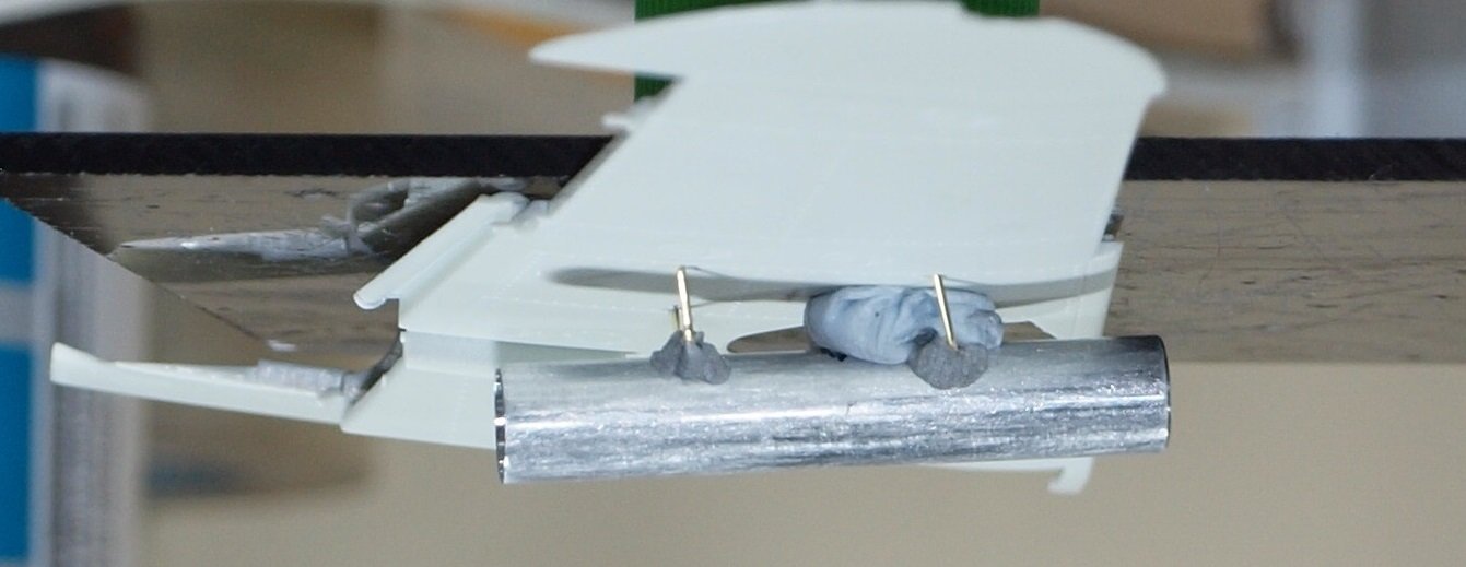
The angles are imperfect, but it is an area which you won;t see unless you're looking real hard. I would never take it to a show. I'm too fearful that It'll get to the venue in pieces. I still have to do the wiring and a little PE.
This little bit of AM by Profimodeller is only 4 tubes, four rockets, a length of copper wire. Some of the PE you're supposed to stack to form 3d shapes. The rockets are solid aluminum making the whole thing quite heavy. I drilled out the rockets to save weight. I also modified the outside of the rockets to get past the brass rods that have pierced the tube.
Nobody will see it when I put the end cap on, anyway. Main thing I have to do is paint the rocket before I is permanently fixed in the tube.
There are two small hooks on the wings that most likely bore most of the weight since they are right on the spar. I made them out of card. I added arrows to make up for the crappy photos.
I was gonna take another pic of everything in place. But trying to align all of the pins and get everything straight is a bit like trying to coax a preying mantis into a sandwich bag, I reckon.
Happy modelling!!
-
5
-
-
Nice looking airbrush work, Kai! I paint outside... so I rarely wear a mask.
-
2
-
-
Still struggling with these mortars. Why didn't somebody at the RLM just come up with a fin-stabilized rail-mounted system like everyone else?? Oh well... no point in speculating.
But now I know why nobody models these...lol
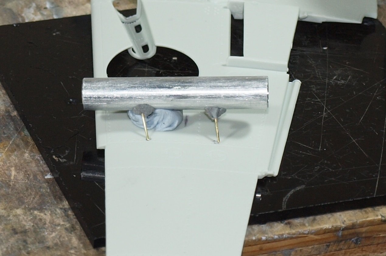
Here are the mounting pins. there is .5mm rod encased in .7mm tube. The longer roads are 13mm long, and the short rods 9.5mm +/- cut accuracy.
Nope... I didn't measure twice.
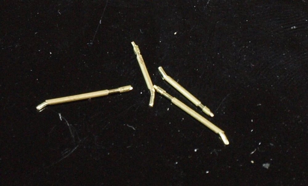
Nothing glued, yet.
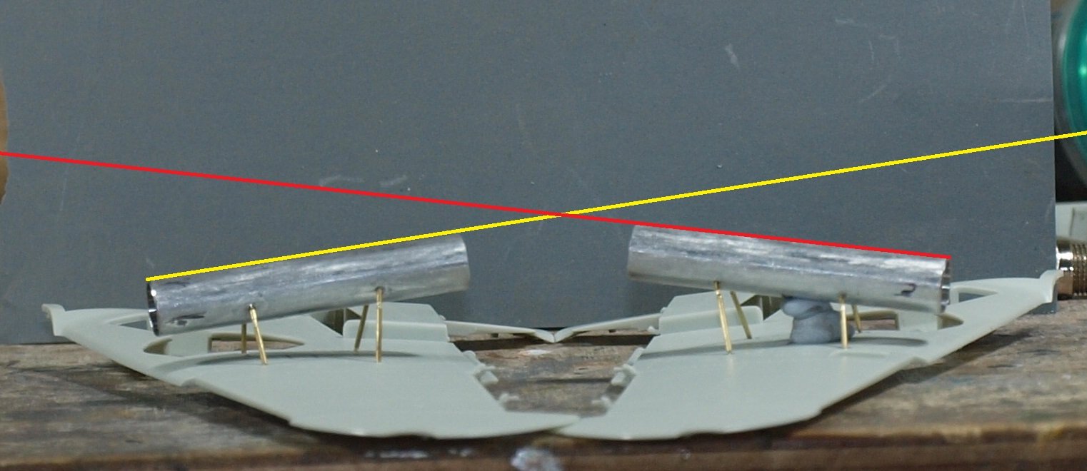
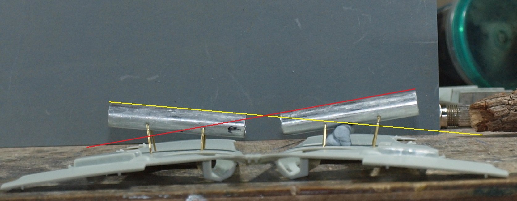
With the tubes now glued to the rods, but only dry fitted to the wings, I used the photo editing program to compare angles.
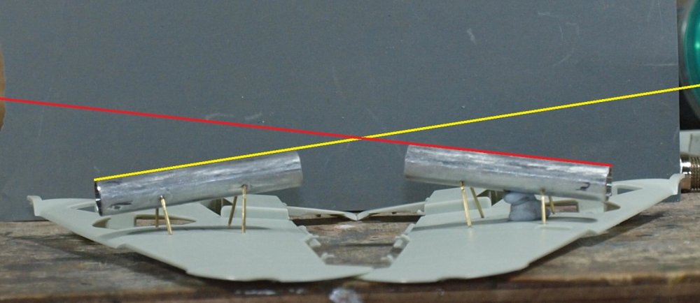
Of course... I can't certain that the camera is square to the subject.... but it only has to be close.

They are situated far enough apart on the plane that checking their alignment would be a serious issue for the would be rivet counter.
Speaking of rivets... there are a bunch of rivets that go the length of the tube. I will use paint and effects to simulate this when finished with all of the mounting pieces.
I still have to add wiring, photo-etch, and the hook assembly that will finally enable me to call this painful part of the build complete.
Happy modelling!
Think I need to make some lunch!
-
5
-
-
7 hours ago, Peterpools said:
Gaz
Nice work for sure and the start of the rocket launcher tubes looks mighty good.
Keep 'em comin
Peter
Thank you, Peter.
-
3
-
-
10 hours ago, Kaireckstadt said:
Hi Gary,
I have found some additional fotos of the installation of the Werfer Granate 21 under the wing of a 109:
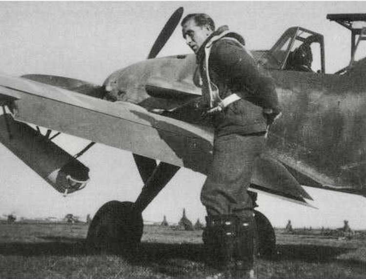
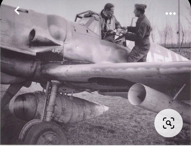
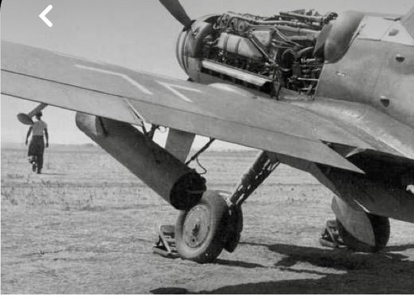
When I compare it to your fotos it comes quite close.
HTH
Kai
Thanks for the great pics, Kai. They make me think I need to extend the struts a bit.
-
4
-
-

Holy Schmokes, John! What a beautiful job!
-
3
-
-

Love this scheme... enjoying you putting it all together, Kai.
-
2
-
-
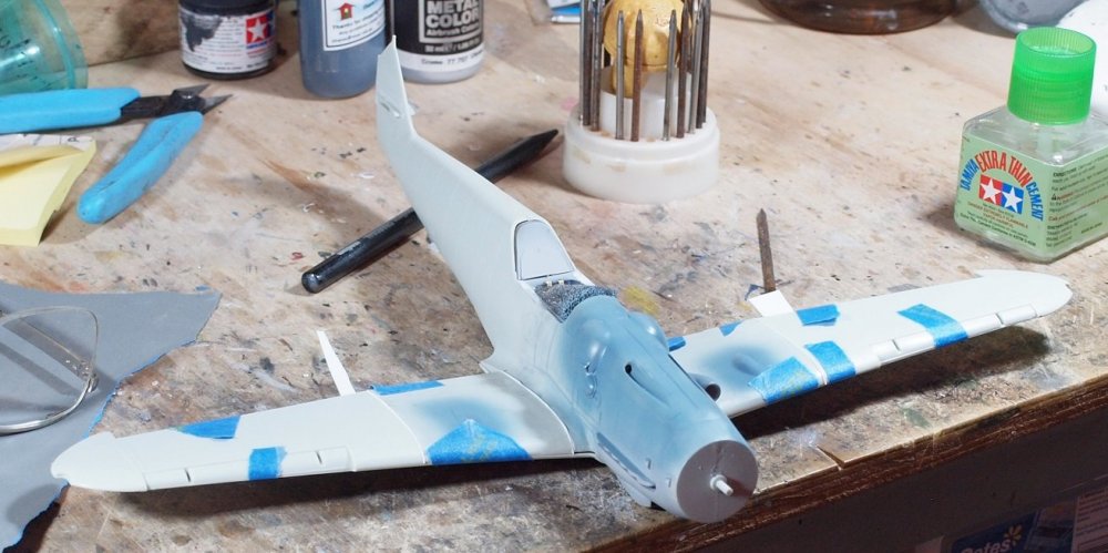
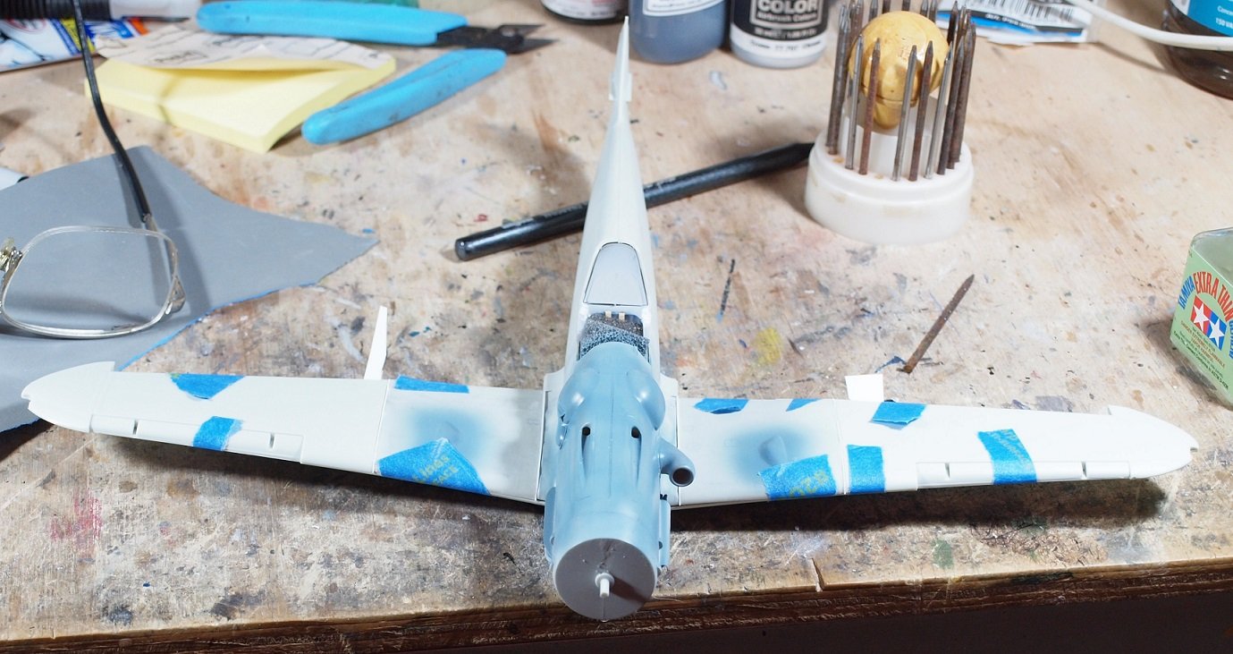
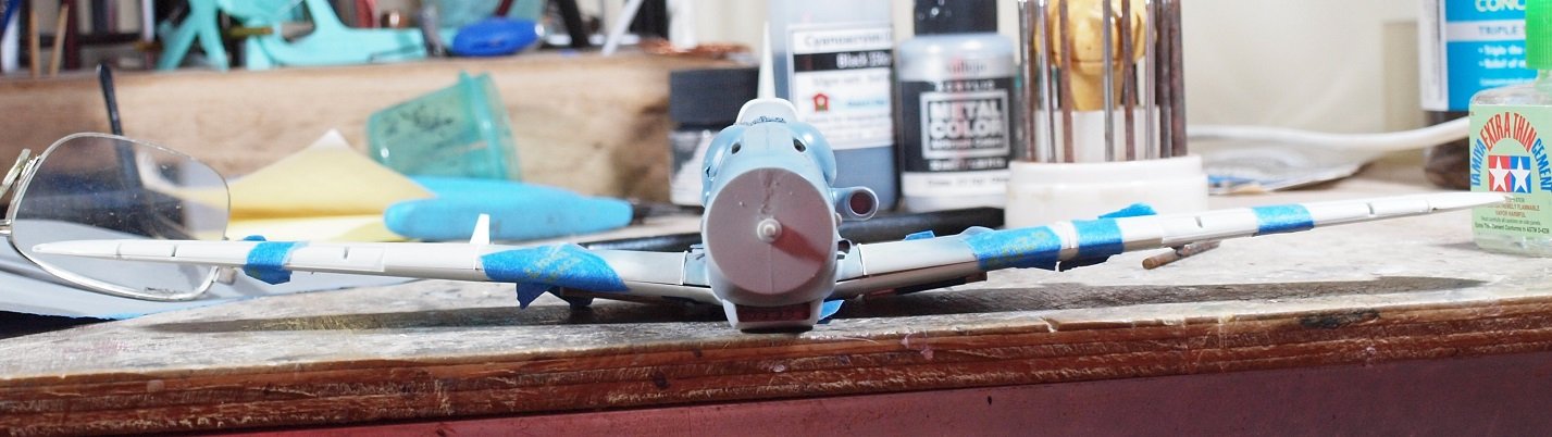
Okay Friends,
It occurred to me that I prepare the wing for the WfGr.21 Rocket launchers. So I stopped working on the upper wing and started taking measurements (from the materials supplied by friends here) and converting them to dimensions usable on the model. Then of course I had to make marks on the model and on the rocket tube for drilling.
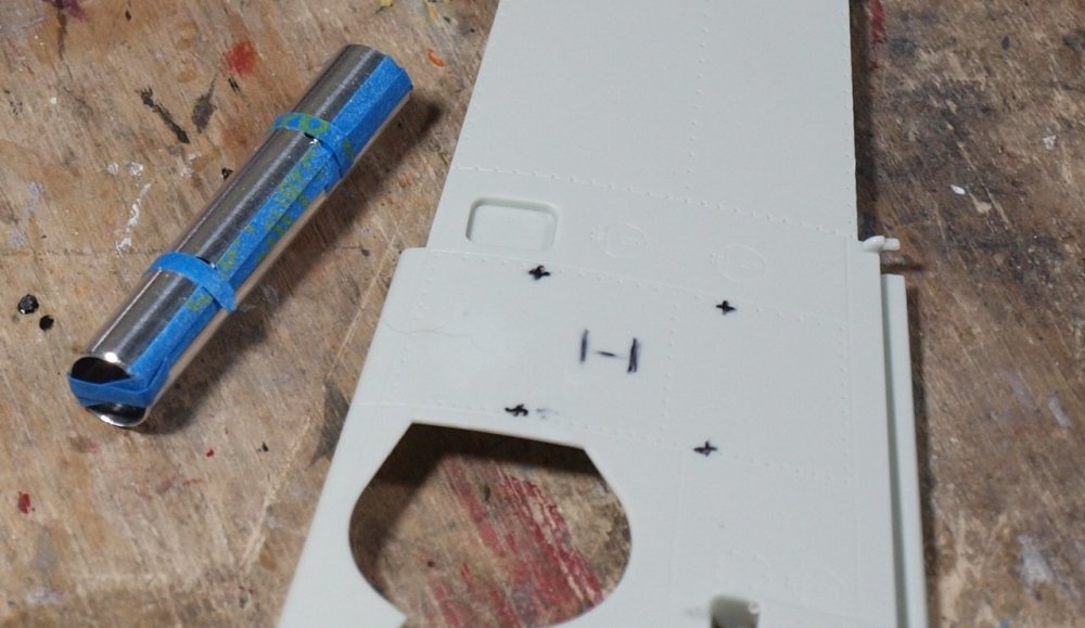
Intersections of the tape show me where to drill.
Hopefully the next series of photos won't be too disorienting.

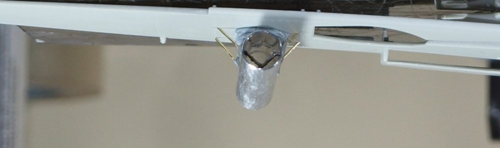
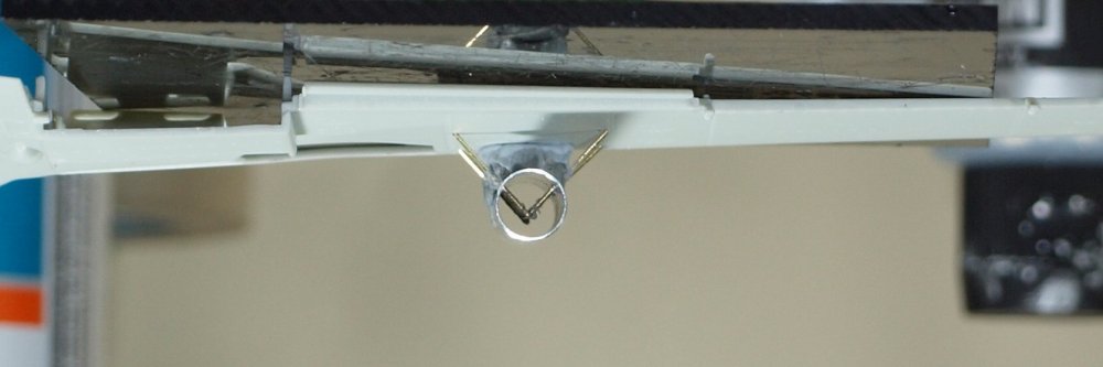
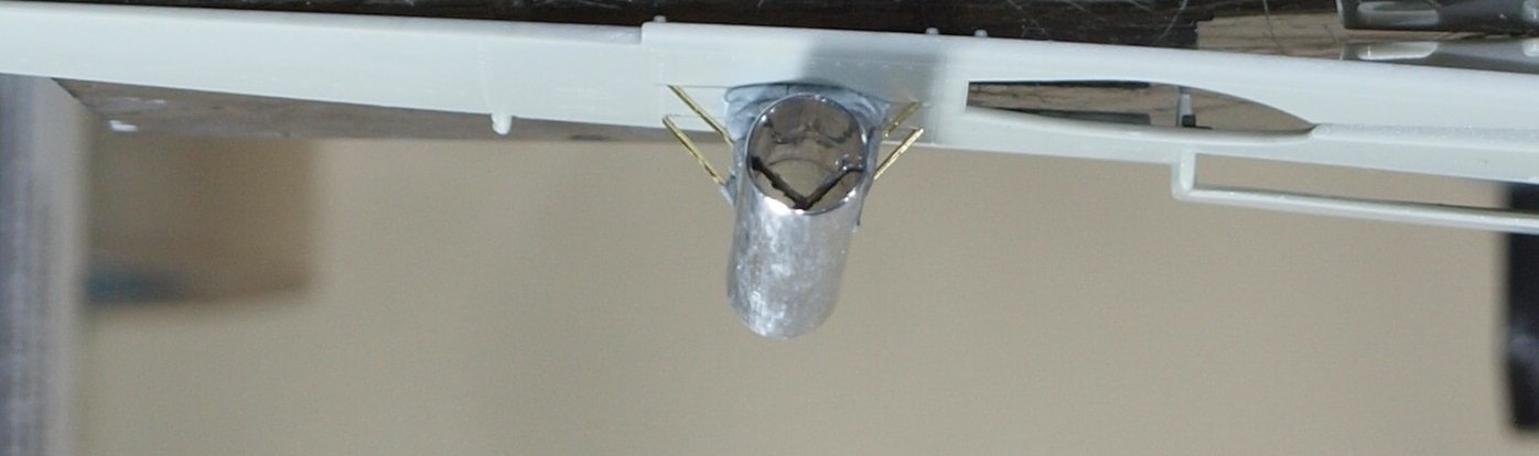
I put them this way to show how they would look underwing. What do you think of my angles and alignment? Everything is held in place with blutack at the moment. When I am happy with the alignment, I will cover the .5mm rod with .7mm tube.
Here is one upside down photo.... if that helps.
-
4
-
-
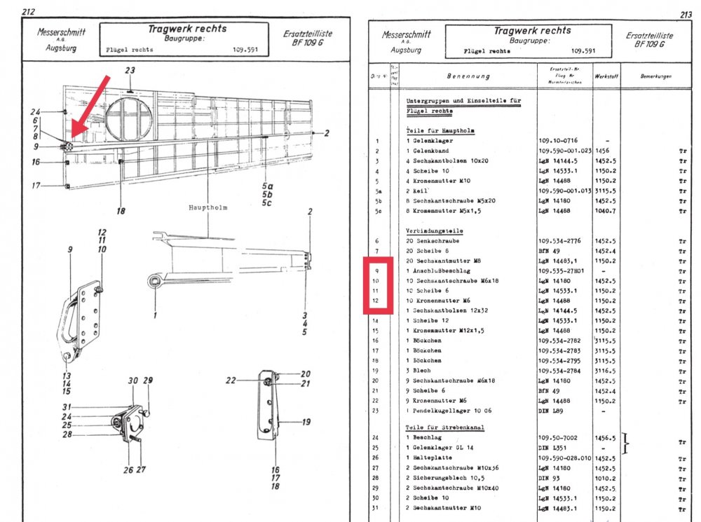
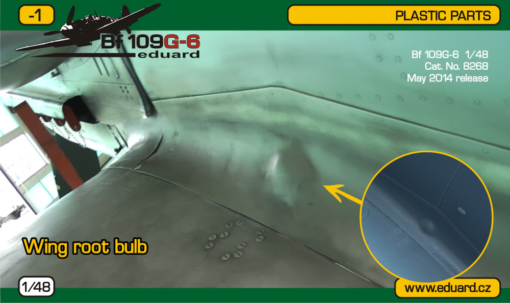
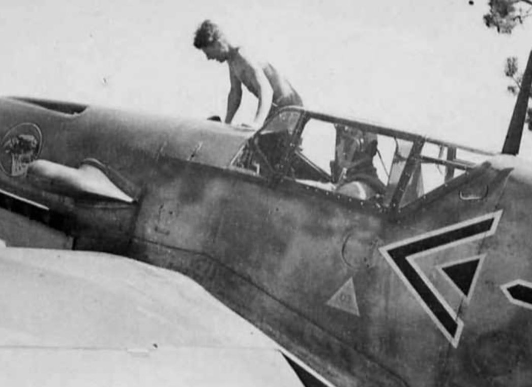
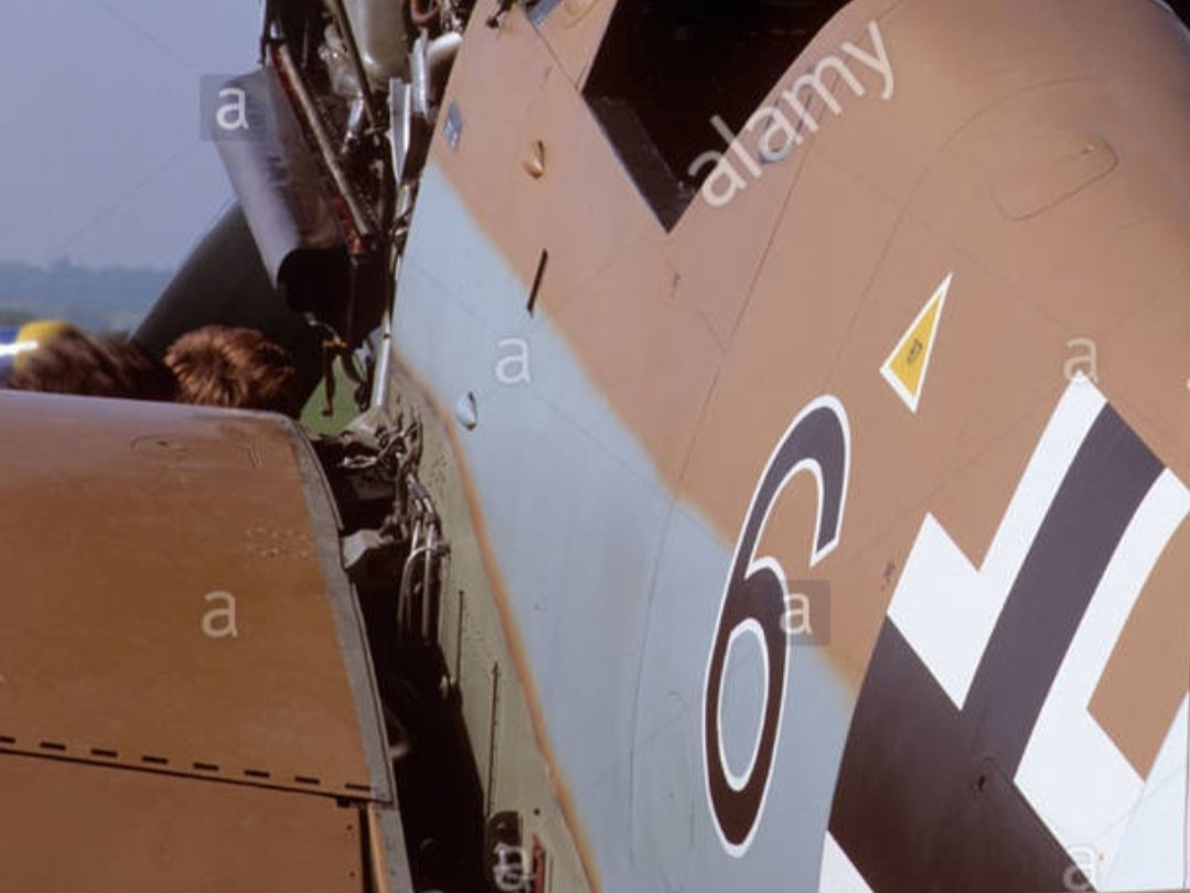
11 hours ago, Wumm said:
You just can't trust restorations...
The Eduard photo shows screws. These really should be M6 x 18mm bolts, according to Messerschmitt documents, but ten per wing is correct.
One of the weaknesses of the Bf109 design was always the single wing spar, and with the introduction of the more streamlined F series variants, speeds and aerodynamic loading increased. Subsequently, some airframes began to lose wings during combat (and others their tails, but due to other issues). The solution was to strengthen the wing at the top interface with an additional brace (part number #9, 'Anschlussbeschlag' on the list) attached with hexagonal bolts, washers and crown nuts underneath (parts 10, 11 and 12). This arrangement continued for the duration of production throughout the War.
Werner Molders' F-1 variant. No bolts visible, and no bulge on the otherwise smooth wing fillet cover panel.

G-6 variant in the AWM... The fillet panel is distended a little here, but the bolts are visible.
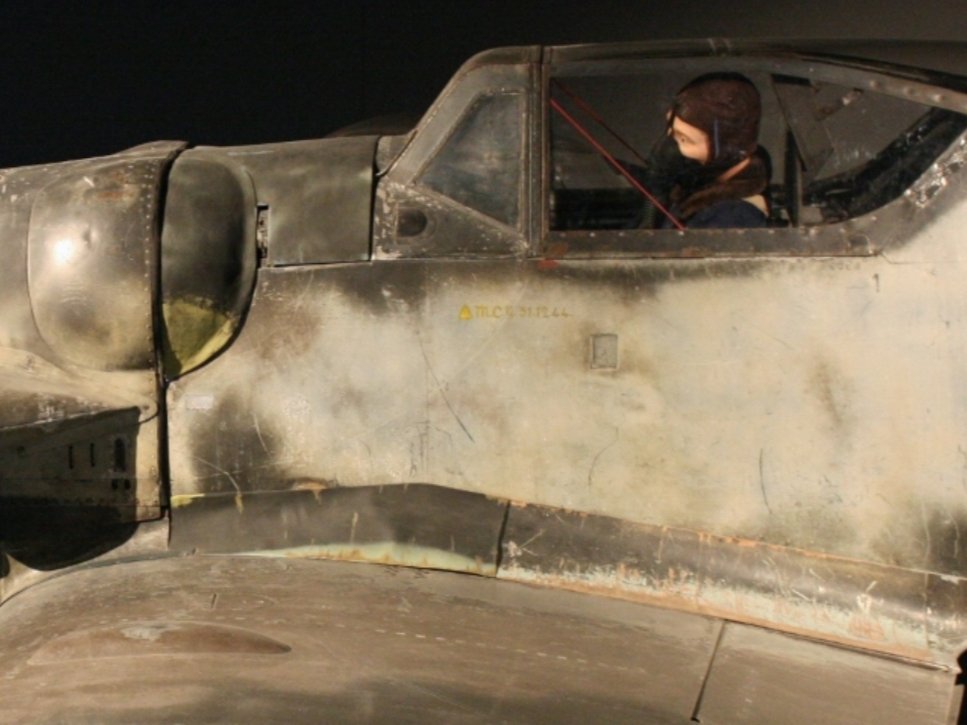
And finally the famous G-2 variant Black 6... With the fillet panel removed, showing the attached bracket position and the wing bolts.

HTH,
S
Steve,
You are a life saver! I actually have a detail book about black 6 and this angle is probably the only one not covered in the book! Thank you very much!
I guess if I accidentally sand any off, I will replace them with a positive bolt head and try to smooth it down and make it look like a screw head.
-
4
-
-
Peter,
Glad to see them coming together so nicely. your painting of the cockpit looks great!
Kinda sad that the Tamiya Stabilators are at a fixed angle.
-
1
-
-
Last night I discovered that my earlier plan required modification. Instead of attaching the shims to the wing root and outer wing, topography on the plastic dictated that I put the shims on the inserts.
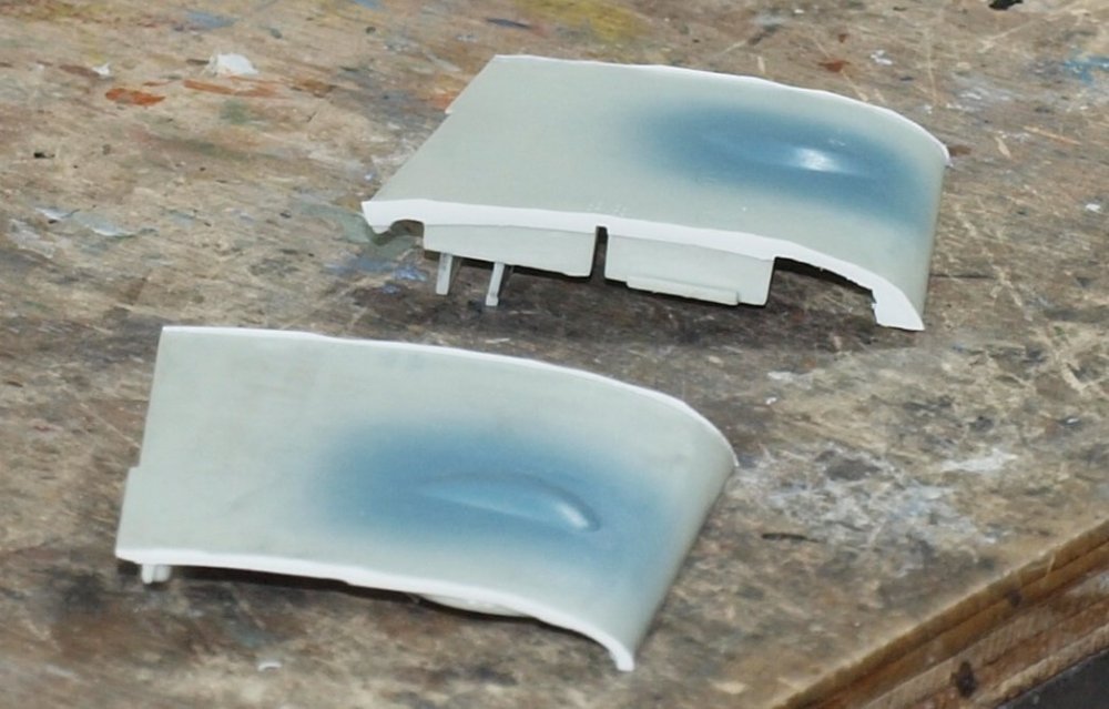
This evening: After repeatedly attaching, removing, and sanding the shims to a proper thickness, some dry-fit photos:


Tomorrow I'll backfill behind the shims with black CA and sand it all smooth.
Here is one for an expert: On every large scale 109 model there is 8 raised screw heads right next to the wing root. However, there aren't a lot of picsw of the area and none that I have show them to stick up above the metal skin.
I found this one today:
Obviously this is an Eduard kit.
Anyone got a picture of the real thing?
-
5
-
-
Looks great! Is that rubber band up to MDOT standards?
-
4
-
-
Getting rid of the over-spray really makes the painting look
.
Bring it on!
-
3
-
-
6 hours ago, KevinM said:
Spreaders in the the bottom of the fuse a "no go"?

Oh, no. There is so much superglue binding the tub to the sides... something would crack.
-
5
-
-
9 hours ago, Bomber_County said:
Gaz, hats off to you for your perseverance on this one. I’ve binned a kit but this one would push me over…..
Thank you Phil. After all of the money spent on AM... I couldn't afford to bin it...lol
-
2
-
 2
2
-
-
2 minutes ago, GazzaS said:
Thank you, Kai. Your Mirage will be something to be proud of. So... the extra effort pays off in the heart if not in comparing the relative ease of other kits. At least, I feel better about mine now.
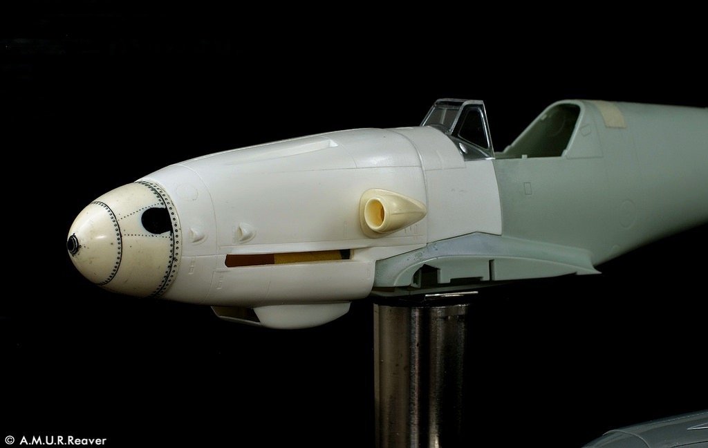
Amur Reaver makes a correction set for the G-10. I've already got mine:

Except for the spinner, it's one big piece.
And apparently they make one for the G6, too...
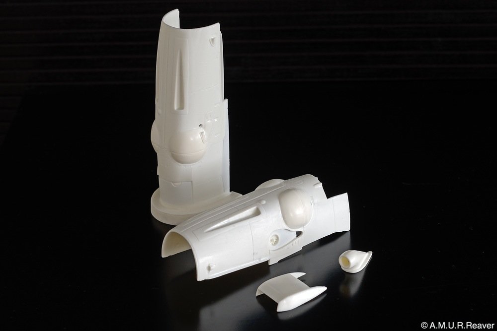
I already had the parts for this build... but you can save yourself some work if you can find it.
-
2
-
2
-
-
13 hours ago, Kaireckstadt said:
What a bad kit Gary! Unbelievable how bad accuracy and fit are!
You did a great job on all the Beulen!
You are right: all time invested in a build to overcome the shortcomings of a kit is lifetime you won’t get back!
The gaps on the wing pieces are horrible! Your chosen method for elimination is the best!
I have 2 G-6 and one G-10 of the same kit in my stash. Will be the next „Mirage-Project“ when I start it (somewhere in the very far future…)🤮
Thank you, Kai. Your Mirage will be something to be proud of. So... the extra effort pays off in the heart if not in comparing the relative ease of other kits. At least, I feel better about mine now.
Amur Reaver makes a correction set for the G-10. I've already got mine:
Except for the spinner, it's one big piece.
-
4
-
-
15 hours ago, DocRob said:
Woah, an outburst of pure frustration and understandable, given what this kit throws at you. In my brain cinema, I will always see the Blues Brothers sing Beulen, Beulen, Beulen,... from now on
 .
.
Said Beulen look good now, I think. Bummer with the needed surgery on the wings. It's not a short gap and on both sides, holy cow.Cheers Rob
Thank you, Rob. I think the worst is over. Really... I feel better about achievements like this than slapping together a 'nice' kit. Sure... It's a pain the the buttocks. Had I failed, it would have been a different matter. But I'm happy now.
-
3
-
-
9 hours ago, Bomber_County said:
Any updates Gaz?
I've been committing my modelling time the 109 build. Lot's of fettling going on.
-
3
-
-
VEry sharp!
-
2
-


He-219A-0 UHU
in LSM 1/35 and Larger Work In Progress
Posted
Nice looking cockpit details, Mark!