crazypoet
-
Posts
826 -
Joined
-
Last visited
1 Follower

Recent Profile Visitors


-
Trumpeter P-47D Razorback
crazypoet replied to crazypoet's topic in LSM 1/35 and Larger Work In Progress
In the continuing saga of “proper prior planning”, I’ve realized that I should have fitted the gun cap inserts on the wing *before* mounting the guns and doing all the internal work in the bays. 😂🤦♂️ The fit of both parts is truly *bad* - huge steps and gaps Getting everything filled and sanded smooth without damaging the gun barrels is the challenge of the moment, not to mention that when I installed them, there was that tell-tale “snick” sound of a bit of CA breaking loose on gun one in the (fortunately for me) open bay - in this case, *underneath* the breach. And of course that gun is now misaligned. Wheee! This is what I get for following the build order in the instructions 🤷♂️😂🤦♂️ No pics yet - they look a right mess at the moment. Once they’re filled and sanded, I’ll figure out how to re-scribe the turn-latches along with re-scribing panel lines and rivets And of course this all happened just before a week-long trip out-of-country, so I have this all to look forward to when I get back late next week -
Those Merlins are pure art!
-
I made a similarly 🤦♂️🤦♂️🤦♂️ discovery once with my own airbrush - but in this case it was in the barrel where the cup connects yah, these things get finicky when we don’t tend to all their nooks and crannies 🤣
-
Yup! One trigger action = one round fired, so still technically a semi-auto Annnnnnd, with black-powder rounds, in 45/70 or even 50/100…! 😎😎😎 it’s a black-powder rifle - but with real teeth 😂
-
1:32nd scale Sopwith 1 1/2 'Strutter' (1.B2)
crazypoet replied to sandbagger's topic in LSM 1/35 and Larger Work In Progress
Following with interest! -
In the US, black-powder firearms aren’t regulated at all, excepting when carrying one in your luggage during a flight (when normal TSA regs apply). No serial numbers needed, no registration. My guess is that they don’t see them as a “threat” I’ve been tempted to build a functional Gatling gun in 45/70, to see how far I can push that 😎 Of course, since I moved to Cambodia it’s all kind of a moot point - can’t get most of the materials here, and getting them shipped from the US would be a nightmare 😂 Though…hmmm…. There are tons of small professional machine shops that would not ask many questions… 😎
-
I love this! I had an opportunity to fly as a “guest” on one of these (J model) during a live-fire training mission way back in the day, and I’ve been in love with them ever since I keeping hoping to find a kit in 1/48, but it seems none of the manufacturers want to take it on I’d like to build a copy of the bird that was lost during Desert Storm (I think it was an H model - have to do some research on that). They stayed on-station too long, supporting a Marine Detachment, and were shot down by ground fire after the sun came up great work!
-
Trumpeter P-47D Razorback
crazypoet replied to crazypoet's topic in LSM 1/35 and Larger Work In Progress
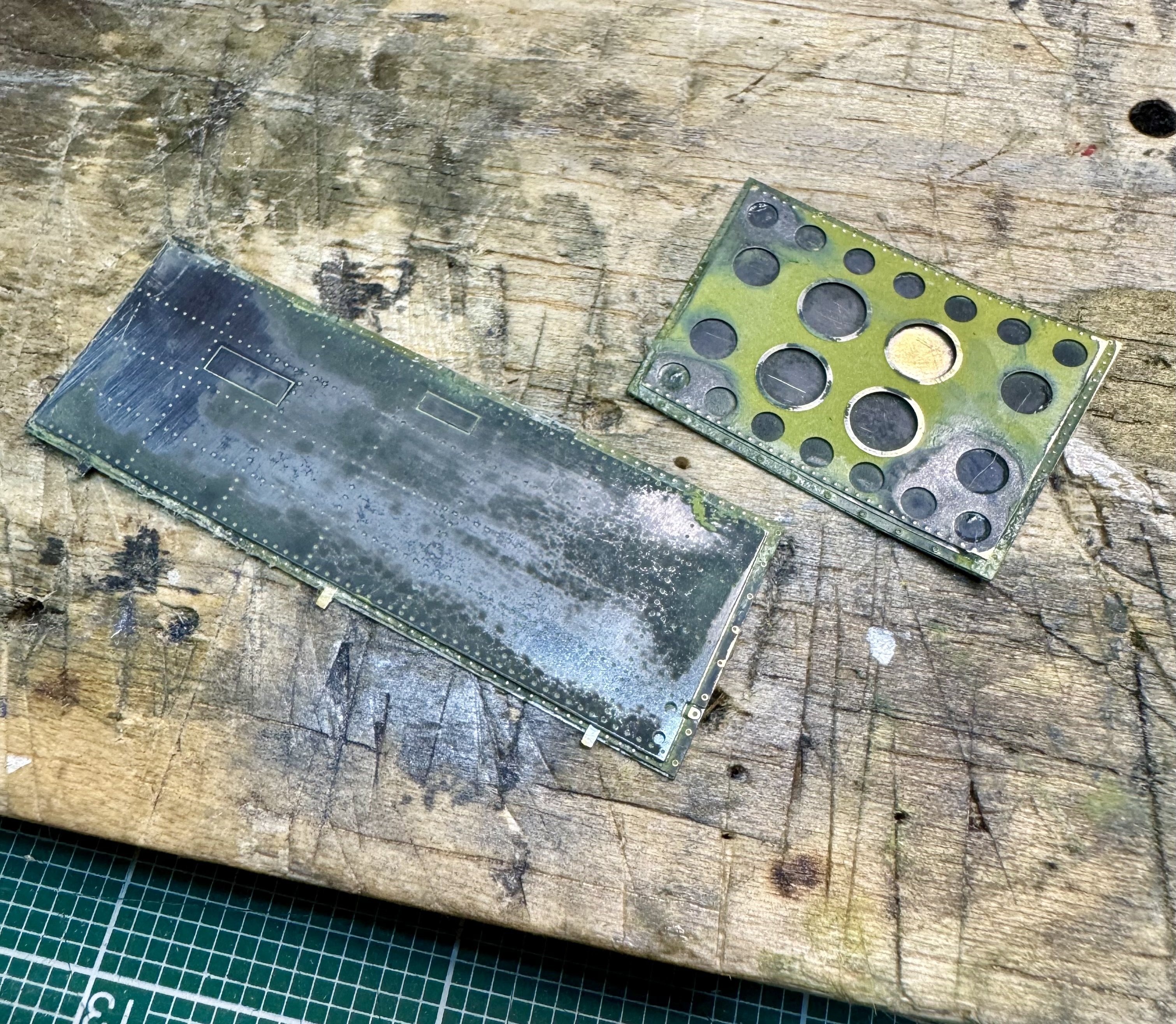
PE is painted up the Duralumin looks a bit bright, but it will tone down once I apply a bit of wash i also folded up and shaped the bay covers. They look a right mess at the moment, due to some paint experiments I did a while back (they were very useful canvases 🤣), but that will all get sorted when I paint the rest of the model Now at least I can move on to attaching the wings and getting this thing up on its legs 🙏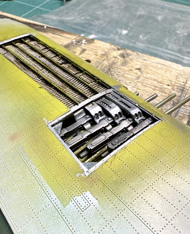

-
Following this! I have the ancient Monogram kit, that I’ll (eventually 🤣) build, also in Linebacker II colors It will be an education for me to stare over your shoulders as you build this one 🙏
-
Trumpeter P-47D Razorback
crazypoet replied to crazypoet's topic in LSM 1/35 and Larger Work In Progress
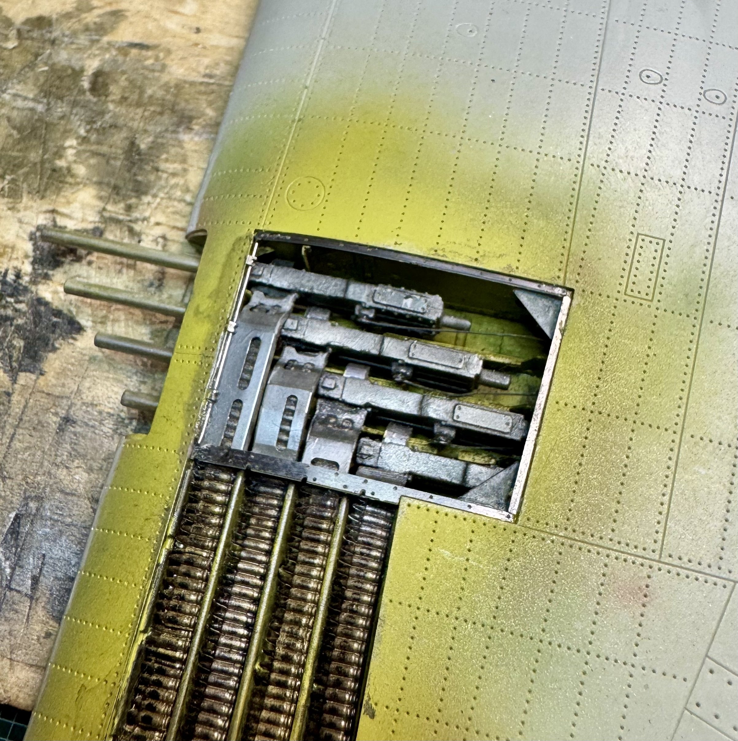
Installed the PE bits around the perimeter of the gun bay - they slotted right in, mostly The piece that bridges across the ammo trays and the ends of the feed chutes was longer than the space, and it took some thinking and judicious trimming. It’s now just long enough that, when installed, it bends up into the airfoil curve that will match up with the panels. I haven’t put any paint on these yet - that will happen later today (my girlfriend is asking about lunch and dinner plans, and those come first 🙏) I’ll do these in Alclad duralumin, I think, with a bit of silver pencil highlights on the fasteners I’m going to try to fit the steel fastener rod across the aft side of the bay (similar to the rod across the forward side). It will take some fiddling around to see if I can shoehorn it into the space and make it look right
-
Trumpeter P-47D Razorback
crazypoet replied to crazypoet's topic in LSM 1/35 and Larger Work In Progress
Thank you! 🙏 I think it will work when taken as a whole - this is an airframe that’s been though a year of great maintenance but hard service, and it will show and FA made a good point to about emphasis in shadowed spaces, to “pop” the highlights just a bit -
Trumpeter P-47D Razorback
crazypoet replied to crazypoet's topic in LSM 1/35 and Larger Work In Progress
Yup - and I know now how to make it better and brighter next time ‘round Using the right paint but with the wrong approach, on a material it wasn’t designed for left things too dull for the space. You're right, it needs to “pop” a bit in that space As Doc said, it should blend a bit better once it’s done, especially taken as a whole, and it will work with the overall weathering I’m planning But I certainly learned something 🤣🤷♂️🤦♂️ -
Trumpeter P-47D Razorback
crazypoet replied to crazypoet's topic in LSM 1/35 and Larger Work In Progress
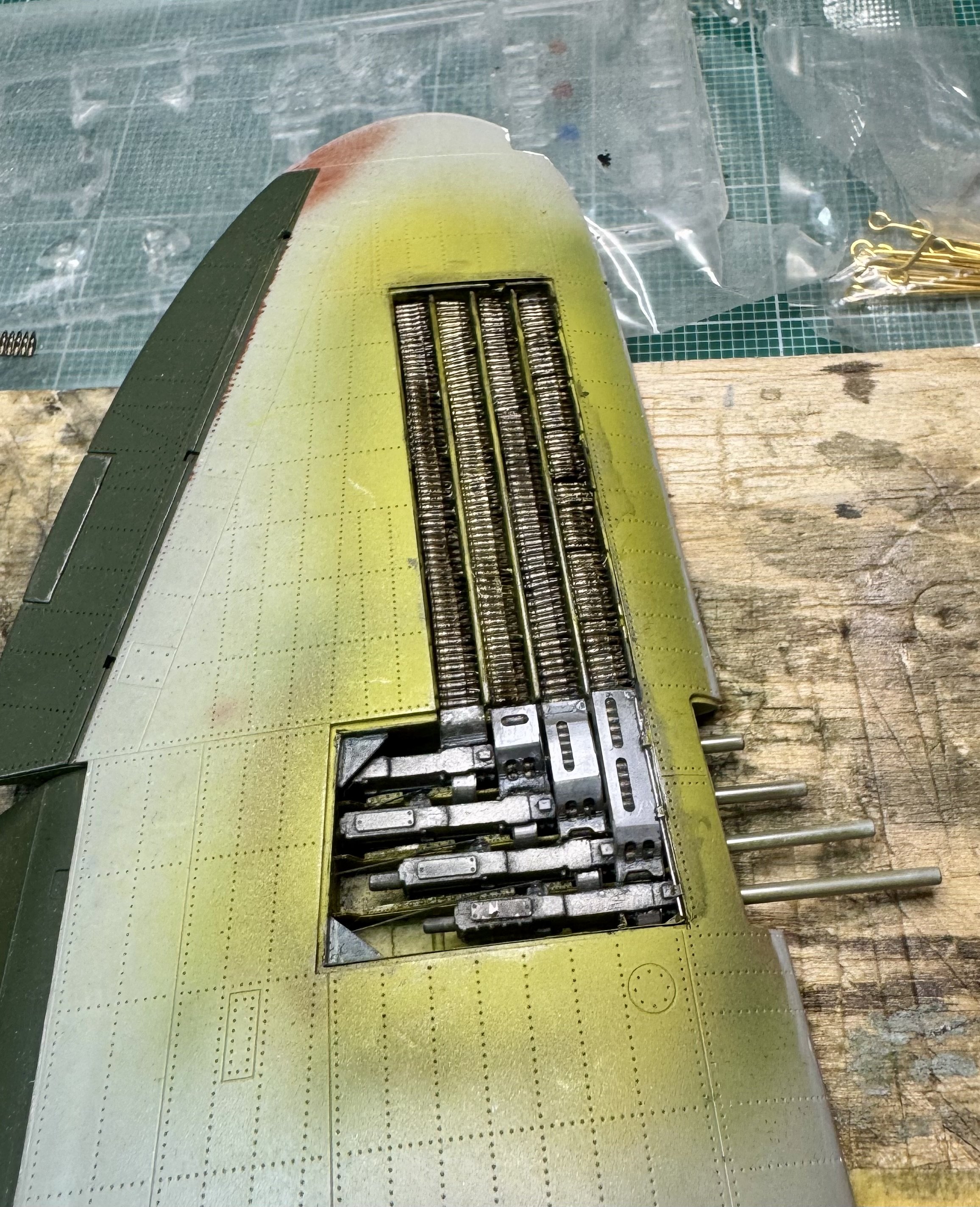
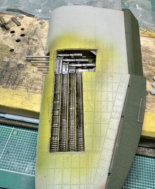
Belts are in and have a gloss coat applied. I’m not 💯💯💯 thrilled with how they look - the brass should be a bit brighter and the links should be better defined (and a lot more even than I could get with slightly shaky hands and a brush 🤣), but I’ll live with it - and promise myself that *all* future ammo belts will be accurate cast resin with realistic links, that I can straighten with a bit of hot water and then airbrush The PE chutes were a bit fiddly to install while stuffed with the rubber ammo belts, but they lined up with no more than the usual amount of cursing, and it’s worth it to see proper links in the chute cutouts I’m chalking this up to “learning experience” and will take a deep breath and move forward. A bit of thin wash once the clear coat dries will help a bit, and then I can finish up the PE in the gun bay and get the wings properly attached
-
Lotus 49C - Ebbro - 1/20
crazypoet replied to DocRob's topic in LSM 1/35 and Larger Work In Progress
This is beautifully done, and the work you did to make everything “work” is inspiring me to power through some of the similar issues I run into - you’re always a good teacher! 🙏 -
Henschel Hs-123 A-1 ICM 1/32
crazypoet replied to Marek Models's topic in LSM 1/35 and Larger Work In Progress
Welcome to the asylum! And great work, there - always a bonus to be able to watch and learn from each other 🙏