
Umlaufmotor
-
Posts
303 -
Joined
-
Last visited
Content Type
Profiles
Forums
Events
Gallery
Everything posted by Umlaufmotor
-
Little things which models bring to life.
Umlaufmotor replied to Umlaufmotor's topic in Hints and Tips
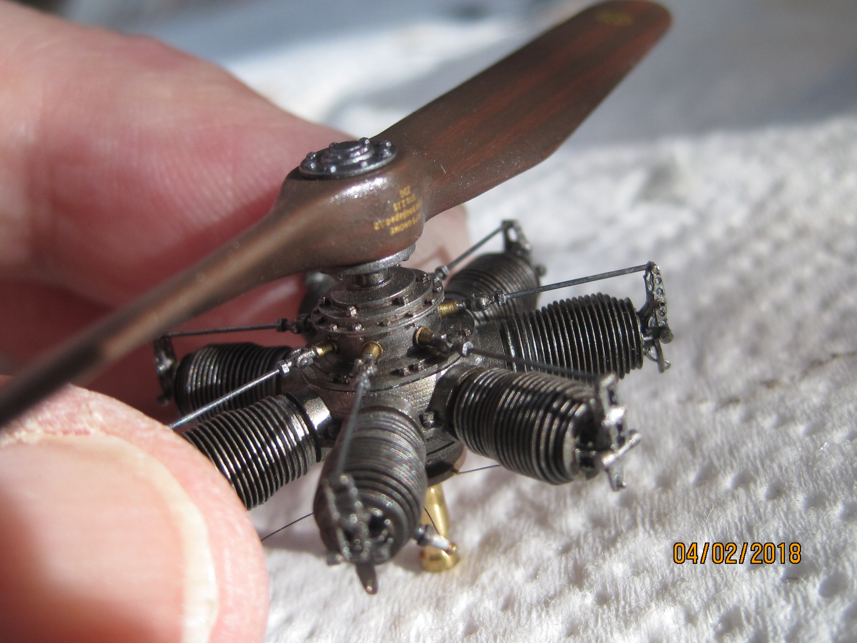
Next, a very prominent Part, the driven Airpump on the Mercedes engines. Most of the aircraft in the Great War were equipped with fuel tanks that are mounted on the installation level - or below - of the carburetor. Lightweight and airworthy fuel pumps were not yet invented. In order to transport the Benzin to the carburetor, the tank was therefore put under pressure. To start the engine, the pressure is generated with the hand pump. If the engine had started its work, the necessary pressure was generated of a driven pump. This pump is very present at the Mercedes engines at least. It is worth to detail a little more this component. The body of these pumps was usually made of brass. At least the Mercedes D.III this pump was usually painted black. Oil, benzin and weathering let the black paint flake off. This effect can often be seen on the original photos . This effect was achieved in the model, in which the pump was first painted in Brass and then in black. The black color was something scraped off with fine steel wool. And here the unpainted airpump of the 180PS Mercedes D.IIIa engine. First the real thing: And here 32 times smaller: With a couple of brass tubes, some bent wire and painting carefully as possible, - this part becomes a small eyecatcher. (Note the color flaking on the painted aluminum cooling water pipe that runs from the engine to the wing radiator) Servus Bertl -
Little things which models bring to life.
Umlaufmotor replied to Umlaufmotor's topic in Hints and Tips
Thank you, @Paulster -
Little things which models bring to life.
Umlaufmotor replied to Umlaufmotor's topic in Hints and Tips
Next, the safety pins to the wheel axles. Quick drilled and shown with thin plastic rod or wire. Here are the two wheels of the Jasta 37 Pfalz D.IIIa........................you know, our old battered workhorse. It has lost the end cap on the white painted wheel. Without end cap .......................... .......................... with end cap. -
Little things which models bring to life.
Umlaufmotor replied to Umlaufmotor's topic in Hints and Tips
Shortly before the take-off. The observer checks the flare gun and places it on his seat. Two become one. Painted with Tamiya semi gloss black mixed with a tiny drop of Tamiya dark brown. Somewhat dry painted with Mr. Metal Color "Iron". The wood grain on the flare gun handle was painted with oil paint. And yes, the gun barrel is completely drilled of course . -
Little things which models bring to life.
Umlaufmotor replied to Umlaufmotor's topic in Hints and Tips
Next, the Wooden decompression handle on the mercedes engines. This lever is actuated before each starting of the engine. The dirty hands of the mechanic, oil, petrol, all that leaves its mark. The black wood protection color will not last long................. Here the real thing: And here 32 times smaller: -
Here I would like to open a small Tread, which will grow up side by side. In this Tread small highlights will be presented, which models bring to life. Things which are very present in the model, can be highlighted by fine detailing. First, the seat belts: These belts were in use several times a day, color abrasions on the metal parts are here absolutely normal. The buckles are painted in RLM02. The edges - or places that are often touched -, are scraped with fine steel wool . Admittedly, that's only a small detail, but by the fact, the belts looks as if they were in daily use. Belts from German two-seaters Belts from German fighters
-
Here is my stock of WNW models. The Fokker E.I is already on the trip. In construction: the Hansa Brandenburg W.29 and the Albatros DV Already completed: One of the two Pfalz D.IIIa. Servus Bertl
-
I always use fishing line for rigging. In most cases 0.10 mm, but 0.12 mm also. I use always 0.08mm for control cables..............here a look into the WNW Hansa Brandenburg W.29 The fishing line is painted with Tamiya paint. I use a mixture approximately 85% aluminum and 15% NATO black, if the aircraft is to be represented relatively new. The older I want to represent it, the more Nato black I use. The line must be painted before rigging. I used micro tube, to represent the leather cover around the end of the rigging wire. Micro means in this case really "Micro". This stuff comes in a variety of diameters. On my Albatross I used a tube with outer diameter 0.289 mm! The inner diameter is 0.254 mm (I used 0,10mm fishing line as an rigging wire). This micro tube comes from electrical engineering and is used as an insulator. The great advantage of this tube: He can cut very well with a hobby knife.... It is very stable and therefore does not break.... He makes an excellent bond with super glue.... He's already the right color to the leather covering of the spliced rope ends represent.... He can be painted very well with acrylic paints.... It saves enormous working time at the rigging. So far so good, unfortunately there is a catch........... This micro tube is disproportionately expensive. More on this later. In the following pictures I want to show you my own way to rigging the ww1-birds. First, the micro tube - the size comparison with a match. We need a piece of 1mm length per cable end. Cut it with a very sharp hobby knife. CAUTION, the particle can jump away (usually on the carpet or in the own eye ) The tube is pushed with a sharp forceps to the wire. And again a match for size comparison. The yellow arrow points to the turnbuckle by which we want to tension the rigging wire. Now the rigging wire is pushed through the eyelet. Always pushes the line from back to front (to you), the bracing will be a bit easier. And now the micro tube is held with the tweezers(see the yellow arrow). Caution, do not press too hard - otherwise can not be threaded through the wire end. If the end of the wire was pushed through the tube, the wire is pulled with tweezers (see the yellow Arrow). The wire marked with the red "x" is pulled in the direction of the yellow arrow. Then, the small tube will pushed toward the turnbuckle, see the light blue arrow. If the wire is stretched and the small hose is in its place, something super glue is then applied (the place is marked with a red arrow) After that, the excess cable end can be cut off very, VERY! carefully (marked with a yellow arrow). The next both pictures are from the bottom of the upper wing. Unfortunately, I failed to take pictures from the same point as in the pics before. But the path is the same. Now, the rigging wire on the turnbuckle is done. Here on the WNW Pfalz D.IIIa is a combination of both, turnbuckle and eyelet. And that's all. The micro tube - or hose -, can be painted with flat clear, I think this also looks much better. And here's a link to the micro tube. http://www.amazonsupply.com/translucent-amber-miniature-polyimide-tubing/dp/B003TLNL5I/ref=sr_1_1?sr=1-1&qid=1359148509&filterBy.feature_seven_browse-bin=5485625011 As I said, a bit pricey. I think, you also comes to a good result with hot drawn Q-tips. ..............but I for myself do not want to sacrifice the micro tube. Servus Bertl
-
Many thanks to all for your kind words. @mgbgtv8steve I have not yet built the Fokker D.VII and the Hannover, Steve. @DoogsATX This is a self made cutting board. This material is GRP (also known as GFK or FR4) and milled from the CNC. This material is extremely hard, PC boards are made of the same material. With a hobby knife or similar cutting tool, it can not be damaged. On this cutting plate, some lines are milled to insert plastic rods or brass tubes. Small pins serve as a stop. It works quite well. Servus Bertl
-
No special powers - eh? I do not believe you, Bo - push the thing back to the WNW 'Work in Progress'. Servus Bertl
-
There are now excellent turnbuckles in the aftermarket area to buy. Well, about four years ago, that was not like that. I had even come up with something myself. I tried turnbuckles through some wood glue present on the rigging wire................ you can, but that does not work convincingly in scale 1/32. I tried it with hot drawn Q- tips .............. this also works - but each of my Q-tips turnbuckle varied in length and diameter. Eventually I found a built-lock in another known WW1 forum. There I found the solution to my problem. Brass tube - this model builder used 0.5 mm thick brass tubes - awesome! Looking for this 0.5mm brass tube I found it even thinner . 0.4 mm!! 0.4 mm x 32 mm arise 12.8mm in real life. It fits! These 0,4mm brass tubes are cut to a length of 2.5 mm. 2,5 mm x 32 arise 80mm in real life. This fits also well. Through the brass tube is pushed a eyelet with a longer end and glued with cyano. The eyelet was made from 0,10mm silvered copper wire. This Turnbuckles I use for control cables as well as for the normal rigging of the wings . ...................and the real thing: Servus Bertl
-
The model is not finished, probably the thread was accidentally pushed by the admin here ...................... or from you, Bo? The barograph is here: http://forum.largescalemodeller.com/topic/644-wingnut-wings-kit-part-e47/ Servus Bertl
-
WNW Alb D.V 4578~17 Jasta B / E. Boehme
Umlaufmotor replied to BoMonroe's topic in LSM 1/35 and Larger Work In Progress
You are here, Bo? Coool. A warm welcome. Just see Boehme's upper wing is still not mounted? ........................ You're slower than me with the albatross. Servus Bertl- 35 replies
-
- 1
-

-
- ww1
- wingnut wings
- (and 2 more)
-
Very good eyelets can be found at Bob Buckles, or are you doing these things themselves What you need is wire with a thickness of max. 0.10 mm. Such wire is often found in old fan motors for PCs. These wires there are in pure copper or tinned copper. The tinned is better, it does not necessarily have painted. A good flat tweezers and an old 0.2 mm drill. This drill is glued with cyano in a plastic stick because the drill can hold up better in the hand. The wire is placed in a loop around the drill and twisted with the tweezers. Cut to length - done. Well, what you can do with it? Several things. You can use as an eye for rigging your wingnut bird. Here on the upper wing of the WNW Albatros . The kit holes are to be too large......... ..........but, we make it even bigger. Here 0.5 mm. In these holes a 0.5 mm plastic rod is glued . When the glue has dried, the plastic rod is cut directly to the wing. In the middle of the plastic rod, whe drill a hole with 0.2 mm hole diameter. Our eyelet is glued into this hole . Pay attention to the orientation of the eyelets , they are always aligned in the drawing direction of the tension wire . See original image............. .............and also 32 times smaller Let the glue dry and paint the eyelets with Gunze RLM02 - done. Now you have your own perfecte homemade eyelets at the correct scale ratio. Servus Bertl
-
First I want to thank you all for your kind words and the keen interest in this "Hints and Tips" thread. Second, I have to tell you, that these techniques certainly are not inventions of mine alone. I'm just trying many ways to go to try many things. Some times I go wrong , some times right. But, what works, I will gladly share with you and I am sure, that many of you have tried already like and implemented. These dents, scratches and bumps were created in a simple way with a file, milling, sanding sponge, sandpaper and steel wool. Here are some pictures of the tools that I use to do so. Dents and dings are formed out of the plastic with the dremmel. Be careful, too fast too much material is removed. Then the milled bump is sanded with 120 grit sandpaper. Thus, the scoring of the dremmel be removed. Now the bump is treated with a piece of sanding sponge . This stuff is great. You can use the hobby knife to cut out small pieces. It adapts to the contour of the bump - almost like rubber eraser. Finally, the bump is polished with steel wool. It is imperative that the cowl is extremely sanded thinner to deform the edges. Then the edges are bent gently with a Circlip. This tool has round cheeks, so the plastic is not crushed . But do not overdo it, a little bit less is better. Here I've overdone it, that is the bottom of the Fokker EV / D.VIII wing.[/url Grinding, grinding, grind again. Now it looks halfway useful on a small area of the whole wing. This built is more than four or four and a half years old, but my error has taken me any desire to continue building it. I hope I have answered at least a part of your questions? And I also hope you understand that google translate sentences halfway? Servus Bertl
-
Most of the WW1 aircraft had a hard life (if they were not shot-down in a factory new condition). A hard life leaves its marks on the skin, see Keith Richards. Oops, sorry Keith. These traces and scars can also be presented on a model. It is very important, that the panel needs to be significantly sanded thinner. Otherwise it is unconvincing in model scale. Thereafter, the cowling edges bent slightly wavy with a flat pliers or a flat forceps. Here the Cowling paneels from the WNW Pfalz D.IIIa. Scratches in the paint should be also presented. Here the spinner of the WNW Albatros D.Va. First, a primer with aluminum. Then a layer of Gunze RLM02 gray-green. This is the finish of metal parts from the Albatros factory. Now, very carefully scratches with a hobby knife were attached. But only so deep until the pure aluminum is revealed. In our case, at last, a Layer matt black was painted over all. Again the same procedure, scratches with the hobby knife. Now on some places RLM02 comes to the foreground, in other places even some aluminum is visible. Notice the small turnbuckle to attach the spinner on the prop-plate. An interesting aspect are scratches or dings and dents on the original photo. This should also - if possible -, be represented. Here at our WNW Pfalz D.IIIa. See the original photo, the yellow circle. Next, the AVIS Fokker EV / D.VIII. This cowling shows the rough handling of the mechanic. Here the WNW Hansa Brandenburg W.29 "ANNE" (I love this kit!!) The original photo shows noticeable dents on the front panel. Here they are 32 times smaller. Invisible? Then get closer. (Sorry for the bad flashlight foto) So, not afraid of scratches, dings and dents on your models in the future. Servus Bertl
-
The exhaust, - not always just a piece of rusted pipe.
Umlaufmotor replied to Umlaufmotor's topic in Hints and Tips
Boahh (that means "WOW" in German) that is an echo. Thank you so much, guys! Now to exhaust from the WNW Albatros D.V The same colors, but painted in a different order. First, Mr. Metal Color "Dark Iron" and then are irregular spots with "Iron" attached. Next, the exhaust was polished and primed with Tamiya matt varnish. At the nodes of the exhaust pipes dark blue pastel powder was applied. Sealed with matt varnish. Now something brown, light gray and white pastel powder was applied. Then sealed with semi-gloss varnish. Inside the exhaust gray-white pastel powder was treated (1917 there was still leaded Benzin) . Do not forget to milled the exhaust much thinner from the inside. Thus, the exhaust look more realistic. But be careful there! ................. Very careful! Servus Bertl -
HPH Catalina 1/32 - model of construction
Umlaufmotor replied to 312_Pomi's topic in Modelling Discussion
As Jeroen has noticed - toilet paper included. Where, I ask myself: Can I built the toilet on the model empty, - or filled?.............. Premium model. And beautifully built, Bravo! Servus Bertl -
Wonderfully built models, excellent painting, convincing aging......................... And the exhaust? Completely rust brown,- about everything - even inside. Too bad, that destroys the entire impression. Why not something little play with the colors. Also, different types of paint can be mixed with each other. Acrylic paints with oil paints,...Water colors mixed with chalk powder......... No? Sure, of course! Here the exhaust from the WNW Pfalz D.IIIa. Three different color can be seen here.... The base color is Mr. Metal Color "Iron" Thereafter, irregular spots Mr.Metalcolor "Dark Iron"..........plotted with a short-haired brush. Important! These colors are NOT polished, although there are metal-containing polishing colors. Finally "rust brown" from Gunze. Also applied with a short-haired brush. In the area of the welding lines a little more rust brown was dabbed. The further aging and weathering was done with brown and black water color. Servus Bertl
-
This was a "born out of desperation" - idea. In my eagerness to finish the tank of the Pfalz D.IIIa as quickly as possible, I have filed down the instrument bezel. It was weekend and etched bezels are not available. But Wingnut Wings also helps us here out of trouble. A drill, a small file, some sand paper, a Resin saw, glue and a little bit "brass" paint - done. Not perfect - definitely not. But it works .......................... take a look into the cockpit from our old battered workhorse Servus Bertl
-
Thank you so much for the many applause! @Erik B: Yes, I will soon post both techniques in "Hints and Tips". Servus Bertl
-
It was necessary in the early years of aviation, that oil and cooling water had to be changed frequently. The cooling water is drained every night from the cooling system and filled again on the next day. During the cold winter period, the cooling water was often drained between the flights to avoid freezing of the cooling system. For this reason we see on original photos very often drain cocks or oil shut-off valves. Here, for example, an oil shut-off valve at the Mercedes D.III/D.IIIa engine. Here, a drain cock on the wing radiator from the Pfalz D.IIIa is visible (left blue arrow). Also on the wing radiator of the Albatros DV / D.Va. These little things are most very nice details. They are also 32 times smaller very nice details on a model. Here at the WNW Mercedes D.III / D.IIIa engine ............ ........................and here on the WNW Pfalz D.IIIa But how can be represented this thing in 1/32 scale? The answer is: With a bit of brass tube, some copper wire, some plastic rod, a steady hand and lots of patience. We grab the cooler the albatross as a test object. First, a 0.5 mm hole is drilled in the correct place on the radiator. A small Resin screw is glued in this hole . In this screw we drill a hole with a 0.3 mm drill. We glued a brass tube with 0.3 mm outer diameter in this hole. Now, we need a plastic rod with 0.5 mm diameter. We drilled a 0.3 mm hole in this rod (yellow arrow) and from the side a 0.2 mm hole (orange arrow). Now, we cut the plastic rod to a length of about 1.5 mm and placed it onto the brass tube. We manufacture the handle of the drain cock from 0.2 mm copper wire . Bend in the 90 ° angle and squeeze it with flat pliers. Cut the copper wire in the correct length (max. approx 1mm!) and glue. The lever down means the drain cock is closed. The lever positioned transversely means the drain cock is open. The drain valve is painted with Mr. Metal Color "Brass", the handle remains in its original color (copper). .............that's all Servus Bertl
-
Of course, James. I used a very thin Resin saw. After this, the cockpit rim was polished with steel wool until the sawn edges were slightly rounded. I used various medium brown and light brown colors to paint the leather rim. The wells were accented with dark oil color broth. Finally, I painted the buttons with Mr. Metal Color "Brass"...........................with the Spite of a toothpick. ---- And many thanks to all for your kind words!!!! Servus Bertl
-
Here are some pictures of my creation of a seat cushion from the Pfalz D.IIIa Please keep in mind, that pilots which were equipped with a parachute ( late 1918) did not need a seat cushion. So, pillows out of the plane when you built a diorama when a Pilot with parachute standing near the plane. We need except a sharp pliers, a good pair of tweezers, nail file and sandpaper, various drills, a good hobby knife and liquid plastic cement a Dremel or something similar to a Dremel. In each WNW-Box is already a seat cushion - well - at least the material from which the seat cushion will to be created. First, two matching pieces are cut out of the WNW-seat cushion material. These two parts are glued together with plastic cement. After the glue has dried, the contour of the seat is marked on the plastic. Cut with a sharp forceps along the marking Now, with a file and sandpaper, the contour of the seat cushion is modeled. The cushion may quietly look a little crumpled. With the Dremel, the pad is slightly dented. Marked the buttons of the seat cushion, then drilled (0.4 mm). With the hobby knife pleats are engraved into the pillow. Always in star formation around the buttons. The holes of the buttons are recessed with the Dremel bit. A thin plastic rod represent the buttons The pillow is treated on the edges with rough sandpaper. We want an old, crumpled and wrinkled pillow. The seam on the pillow is made with an extremely thin plastic rod (drawn over a candle flame), glued with liquid plastic cement. Finally, the seat cushion is polished with fine steel wool - done. And here is the seat cushion from the WNW albatros D.V Servus Bertl
- 1 reply
-
- 1
-
-
During the Great War, the Pilot - and the Observer seats were manufactured in the airplanes of all sorts of different materials. There were seats of braided raffia, wooden seats , simple wooden seat boards - or later -, armored seats from bullet- resistant steel ( Junkers J1 ) or aluminum . In most cases, the backs from the seats were covered with a thin fabric or leather. This seat cover in leather or fabric can be shown relative easily with paint or decals. But there is also another way: This is the seat of the Hansa Brandenburg W29. The seat is actually covered with a thin material. In our case, with simple tinfoil. First, the paper is cut into the appropriate size . After, the seat is treated with a very thin plastic cement. Now, the paper is pressed onto the fresh adhesive. In contrast to my face - wrinkles are here welcome! The tinfoil is bent about 1mm around the edge of the seat . The tinfoil is cut along the seat back with a sharp scalpel blade. This edge is fixed with superglue. Allow to dry. Now the seat can be painted. Tamiya dark brown was used as a base color. Above the orange line that Brown was brightened somewhat , below the blue line was slightly darkened with smoke. Washing with black-brown Oilcolor. Then sealed with clear coat. A extremely thin plastic strip was attached as a seam on the seat cushion. The buttons were painted with Mr. Color Metal "brass". Here is the seat of the Pfalz D.IIIa. This seat cover should look old and a bit worn. It was used a darker brown than on the seat of the Hansa Brandenburg. All seats edges was a very light brown color imitated scraped leather. The seat cushion is not yet final painted in these pictures. Servus Bertl