
Umlaufmotor
-
Posts
303 -
Joined
-
Last visited
Content Type
Profiles
Forums
Events
Gallery
Everything posted by Umlaufmotor
-
Wingnut Wings WNW Fokker E.I - E.I 5/15 -
Umlaufmotor replied to Umlaufmotor's topic in LSM 1/35 and Larger Work In Progress
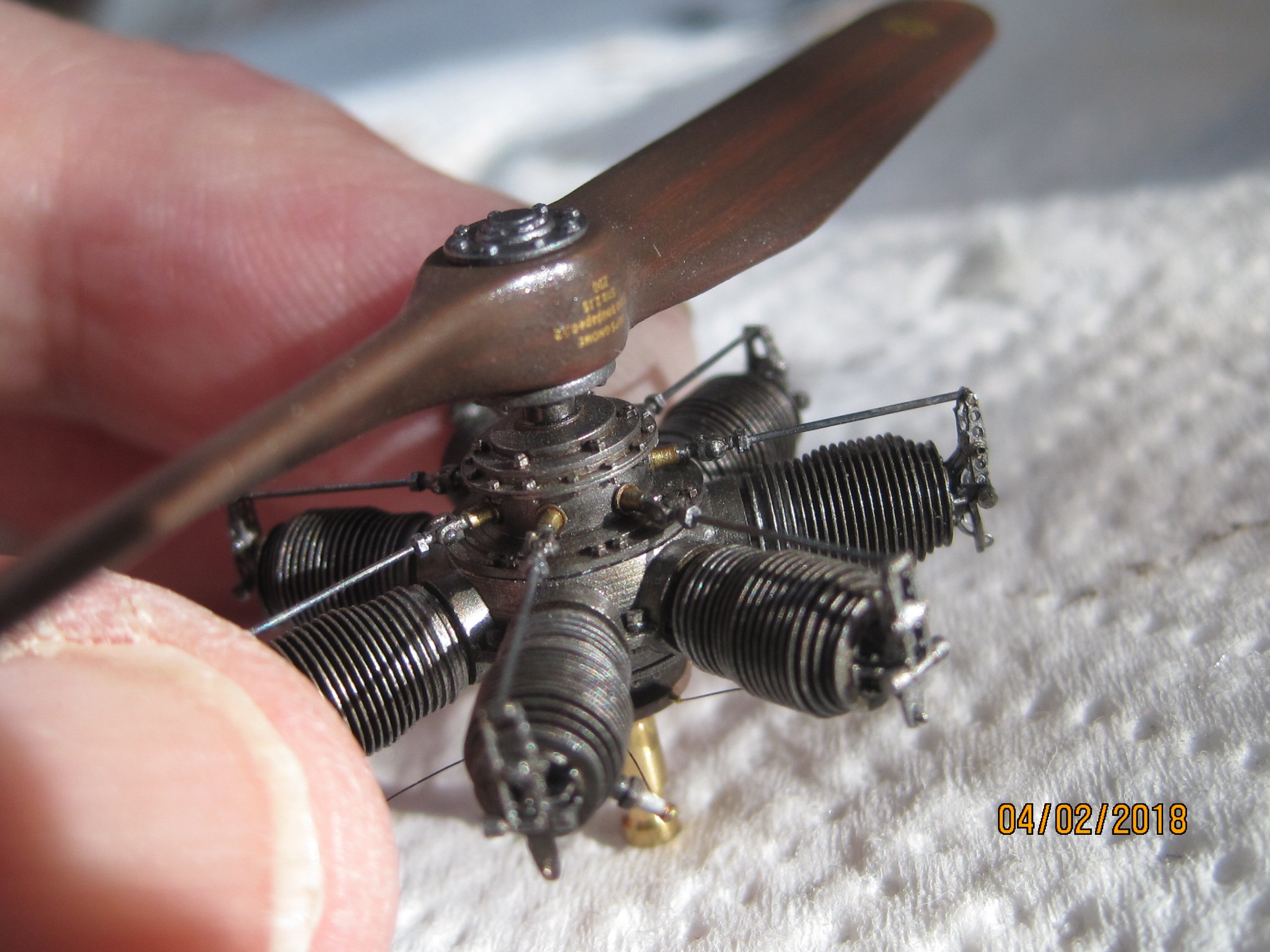
Here can be seen the Front cowling and the top cover . The MG-control mechanism may not work as it was presented in the model. The Front cowling could not be removed in the original, without degrading the MG mechanism. That would make no sense. I'll change it later. I hope it still exist good Images to be able to recreate this correct............................... The "Fokker-screws" (red circle) were also drilled out. Servus Bertl -
Wingnut Wings WNW Fokker E.I - E.I 5/15 -
Umlaufmotor replied to Umlaufmotor's topic in LSM 1/35 and Larger Work In Progress
The abraded rivets on the Cowling were presented with thin hot-drawn plastic rod. With fine steel wool, the "selv-made plastic rivets" were ground until only small elevations are visible. Servus Bertl -
Wingnut Wings WNW Fokker E.I - E.I 5/15 -
Umlaufmotor replied to Umlaufmotor's topic in LSM 1/35 and Larger Work In Progress
Well, I love my Dremel ........................ The top cover was also milled thinner in the fuel gauge, the filler neck, and the MG mount. This gives the impression that these parts are realy made of thin aluminum. The two fuel caps were also removed. Servus Bertl -
Wingnut Wings WNW Fokker E.I - E.I 5/15 -
Umlaufmotor replied to Umlaufmotor's topic in LSM 1/35 and Larger Work In Progress
The two side panels have also been thinned down at the edges. These edges were slightly bent wavy to leave a used impression. Servus Bertl -
Wingnut Wings WNW Fokker E.I - E.I 5/15 -
Umlaufmotor replied to Umlaufmotor's topic in LSM 1/35 and Larger Work In Progress
Then the engine cowling. The attachment points were less well represented by WNW. This Cowling was kept and screwed in the original with two steel cables. I also wanted to represent these Details on my E.I. First, the cowl was abraded with sandpaper, and thereafter attached the two recesses for the tensioning cables. Next, the Cowling was heavily and veeeeery careful thinned with an Dremel. How thin? Well, you see here a pair of tweezers with the imprint "rust-free" at the end of the tweezers......................... .................. you can see this print almost through the plastic. Servus Bertl -
Yeah, I know - the WNW Albatros D.V Ltn. Adam is not finished yet, the Hansa Brandenburg W.29 also not yet and the Mercedes D.IIIa - engine must also wait. I'm also still busy with the Fokker V.4 http://forum.largescalemodeller.com/topic/566-fokker-dreidecker/ - but I have no desire to continue building this little Dreidekker. Well, so I do not get bored, I started with the WNW Fokker EI. The EI 5/15 by Kurt Wintgens with the high-mounted wing. This thing will be a strictly OOB built .............. no super detailling and no-frills or so............... Ahh - stop - I will use the Taurus Oberursel U-0 Umlaufmotor and HGW-Seatbelts First I started with the cockpit. Here, all four turnbuckles were removed for the hanger bracket to the rudder pedals. Brass turnbuckles will be mounted later at this point. Servus Bertl
-
Hi Michael, I have seen this engine stand somewhere on the web - possibly on the webside of Wingnut Wings - but I'm not sure. This little thing is made very simple from a handful of matches. A little bit oil paint over it - done. Servus Bertl
-
He, he - the "Borgward" is a cool thing Servus Bertl
-
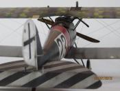
Fokker E.IV 161/16 flown by Lt. Hans Müller
Umlaufmotor replied to JeroenPeters's topic in Eindecker GB
Hi Jeroen, here are some pictures which you may be a help. I found it somewhere on the web, years ago. Servus Bertl- 93 replies
-
- 1
-

-
- fokker
- fokker E.IV
- (and 1 more)
-
Looks good Sasho, -- and I love orange Servus Bertl
-
Taurus Models 1:32 Oberursel U.0 and U.III rotary engines
Umlaufmotor replied to JayDee's topic in Aircraft Reviews
Yes, these nice little things are really high class. I have from Taurus the U-0, the U-1 and the Monosoupape at home and I have just ordered the U-III. This mini rotary engines evaluate on even further the superb WNW - Eindecker and D.H.2 kits. I highly recommend this Taurus engines. By the way, there are only a few U-1 in stock at Taurus models. Servus Bertl -
..............................the flying Dutchman! Servus Bertl
-
Fokker E.IV 161/16 flown by Lt. Hans Müller
Umlaufmotor replied to JeroenPeters's topic in Eindecker GB
I WANT ONE HUB, Jeroen!! Servus Bertl -
@Grant Hi Grant, yes, I can remember this cutting board is a selfmade - tool. Drawn in AutoCAD and milled on the CNC machine. The material is GRP (also known as GFK or FR4) . This material is extremely hard, PC boards are made of the same material. With a hobby knife or similar cutting tool, it can not be damaged. Some lines are milled to cut plastic rods or brass tubes on this cutting plate. Small pins (Diameter 1mm) serve as a stop. You can cut plastic-rod and thin brass tubes with a sharp blade. Thicker brass tubes or aluminum tubes can be cut very well with a resin saw. Please note, this board is not a thing of Magic !!, --- but It works quite well for me. The downside is, it is a little bit expensive to produce, - because the material and the miling time from the CNC-maschine are a bit expensive. Unfortunately I have none more at home. Servus Bertl
-
@Guy5Y Hello Guy, this is the Mercedes D.III / D.IIIa-sprue from Wingnut Wings, part No. 132E0005. http://wingnutwings.com/ww/product?productid=3060 This will be a stand-alone model............................................except I screw up the paint, then I hide the motor in a Roland D.VI with closed cowling Panels Servus Bertl
-
I love this thing. Absolutely, absolutely first class, congratulations!! Servus Bertl
-
Here are some recent pictures. Since yesterday I have been working back a bit on the Mercedes engine. The water pump is now in place. The smaller brass tube (yellow arrow) leads on the original engine to the grease pump in the cockpit. The Bolts on the exhaust side are also mounted. Tamiya tape cut into narrow strips, used to represent the pipe clamps. The decompression lever is also mounted. This is the kit parts, however some refinishing. Also note the recess for the strap for the Magneto (yellow arrow / circle). More "comming soon" ................................. Servus Bertl
-
The two float chamber of the carburetor are also completed. Something Tamiya tape, drilled a few small holes, some scratch-build, a few brass parts and some paint - done. This is now just about the current construction progress . And yes I know, I am far away from a "quick-build".............................. Servus Bertl
-
The drive housing of the camshaft, water pump and ignition has also been revised. The lack of seam (marked in blue) was attached with thin plastic rod and liquid glue. All screws were replaced with metal screws or resin screws. Servus Bertl
-
Now to the ignition system. The mounting for the loop of the spring for the ignition timing is made of a thin plastic rod. The eyelet was bent from wire. It was applied only to one side of the motor, a eyelet. The two magnetos are detailed a little bit ................ Servus Bertl
-
On the D.IIIa kit engine two screws and a bracket missing on the oil pan. Wingnut Wings considering only the D.III engine here. The casted kit screws were replaced by fine Resin screws. Servus Bertl
-
Also at the bottom of the oil sump are some things to detailed. I am not finished here yet, it still lacks a few little things. Servus Bertl
-
The lack Bolt flange on the carburetor was built from plastic waste. Servus Bertl
-
Here the oil level control valve on the oil pan. The first -one was a liiiittle bit too big - but the smaller -one is in scale.
-
Hi James, yes, that was the biggest challenge with the water pipe. Believe it or not, I held each cylinder in my Hand when I drilled the "waterpipe-hole". I've tried using the free mind to achieve the right angle. The right angle at the start to drill the hole is the secret. If this angle is right, then the rest is (relatively) easy. Servus Bertl