FME erk
-
Posts
518 -
Joined
-
Last visited
Content Type
Profiles
Forums
Events
Gallery
Everything posted by FME erk
-
Tamiya 1/48 Lancaster finished
FME erk replied to JohnB's topic in LSM 1/32 and Larger Aircraft Ready for Inspection
Cracking job on that John It may be a 40+ year old kit (1977) but you have turned out a model that is as good as todays standards . . . thanks for sharing Ian -
Tamiya F4U-1A Diorama
FME erk replied to Kaireckstadt's topic in LSM 1/35 and Larger Work In Progress
I find that you fellas that put so much detailing into these kits both inspiring and over whelming . . . I have never been a serious modeller but I do try and do the best I can, perhaps because I have other hobbies such as British lorries of the 60's. I can certainly recognise superb craftsmanship when its displayed like this and both kai and Rob, you have certainly gone to town with the detail and the weathering. There is much to be admired Thanks for sharing Ian- 19 replies
-
- 4
-

-

-
- tamiya 1/32
- eaglecals
- (and 2 more)
-
Lancaster ND644 in 32nd scale
FME erk replied to FME erk's topic in LSM 1/35 and Larger Work In Progress
Hi Gazza I tink I was 'lucky' as the break was fairly clean with both parts having flat edges. I used Tamiya thin on the inside on the tabs and put plenty on. When that I had dried I then applied the HK sprue glue which, and I think I am correct, didnt shrink because its the same plastic as the kit. I did use Mr. Surfacer when correcting the wings issues and I gave that several weeks before sanding that and so far, it still looks OK. I shall be applying a coat of primer in a day or so to look for any flaws then I shall start the scribing . . . . Cheers Ian -
“Dinghy” Young’s “Dambusters” Lancaster
FME erk replied to Wingco57's topic in LSM 1/35 and Larger Work In Progress
Ho ho ho . . . here we go with another big 'un If I remember rightly; AJ - A ED887/G . . . looking forward to seeing this -
Lancaster ND644 in 32nd scale
FME erk replied to FME erk's topic in LSM 1/35 and Larger Work In Progress
Its been around 48hrs since the fuselage was glued . . . I have sanded off the excess that was ousing out and found a couple of 'holes' that I have now filled with HK Sprue glue. I think its going to turn out OK More to come in a few days Ian
- 225 replies
-
- 10
-
-
Lancaster ND644 in 32nd scale
FME erk replied to FME erk's topic in LSM 1/35 and Larger Work In Progress
A photo from the internal showing the HK sprue goo . . . Thanks for looking in Ian.thumb.JPG.450d1fdfd70c21ed09258fc62ba38942.JPG)
-
Lancaster ND644 in 32nd scale
FME erk replied to FME erk's topic in LSM 1/35 and Larger Work In Progress
How it appears . . . Two FMA's to help me out . . ..thumb.JPG.70ac15b6cd72d4761a477f37696a194e.JPG)
.thumb.JPG.09425c24b86b5bea3d30d6bc7beb58e0.JPG)
-
Lancaster ND644 in 32nd scale
FME erk replied to FME erk's topic in LSM 1/35 and Larger Work In Progress
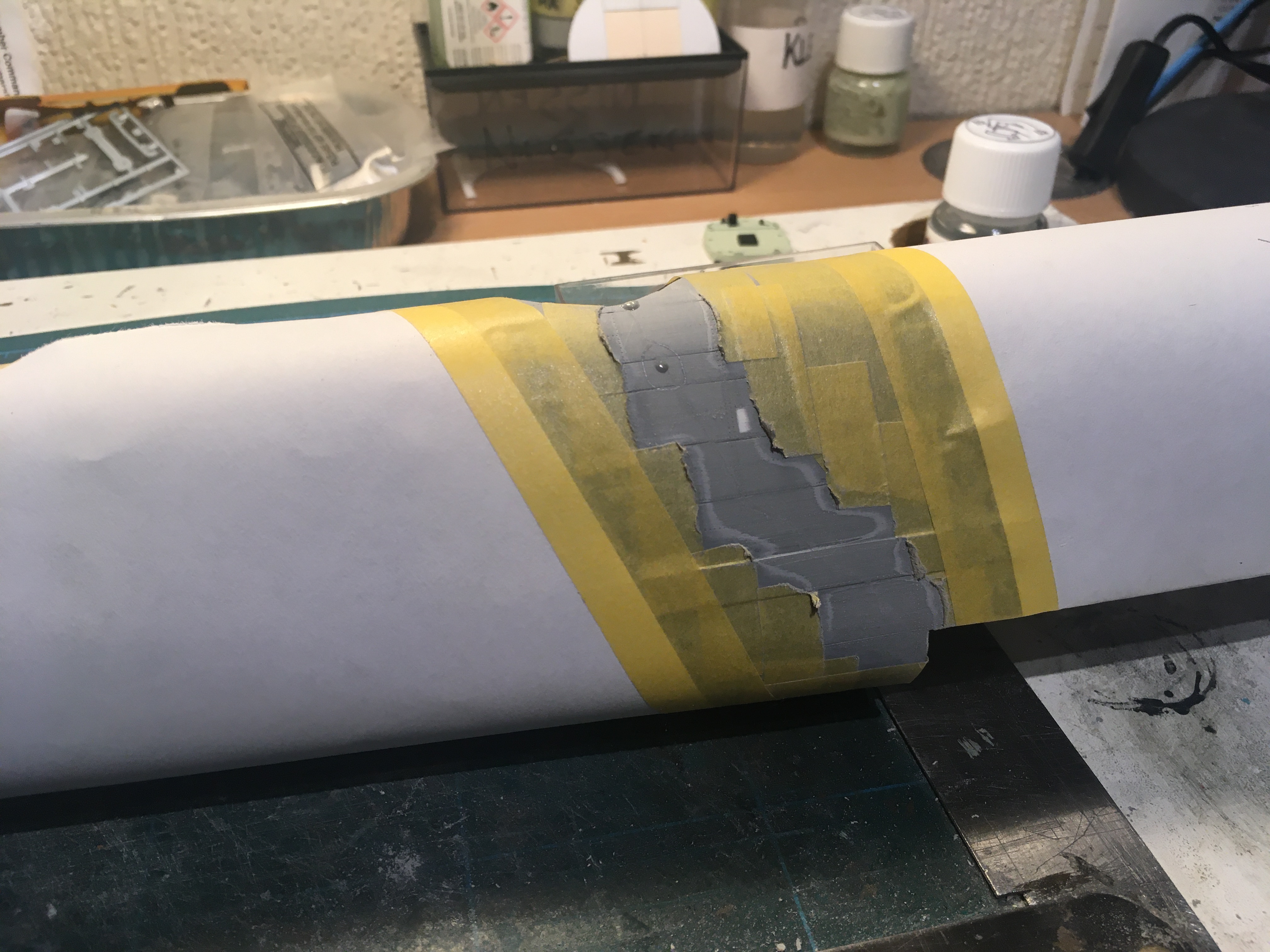
I have made a start on the repair of the fuselage . . . I took measurements from the opposite side of the fuselage of the oblong shapes in certain positions, hence the numbers. They are just shown in place, fortunate the break is as clean as a flat edge rather than in splinters. I shall initially used Tamiya thin and apply only on the inside face and squeeze together. I shall be taping the two fuselage halves together to ensure that both faces are flush and I dont end up with a slightly bent repaired half . . .. Those oblong shapes where there isnt a tab I shall apply HK Sprue glue via the bomb-bay opening and thro' the mid-upper turret aperture. Here's hoping . . . Ian.thumb.JPG.7c1cdf30d3e724d962c443cdb662bbac.JPG)
-
Lancaster ND644 in 32nd scale
FME erk replied to FME erk's topic in LSM 1/35 and Larger Work In Progress
Your so right Dennis, I will take a day or two to consider the best way to attack it . . . cheers Ian -
Lancaster ND644 in 32nd scale
FME erk replied to FME erk's topic in LSM 1/35 and Larger Work In Progress
Thanks chaps for your replies Give it a couple of days and I will have to resolve the issue one way or another . . . Ian -
Lancaster ND644 in 32nd scale
FME erk replied to FME erk's topic in LSM 1/35 and Larger Work In Progress
Carl I do have all the clear parts but as you know, there is no external detail . . . . -
Lancaster ND644 in 32nd scale
FME erk replied to FME erk's topic in LSM 1/35 and Larger Work In Progress
Well its a fine sunny morning in my part of England, no snow as seen in other parts . . . Having rubber down the fuselage windows I thought I would spray some primer onto see if there are any flaws A gust of wind blew it from the shelf . . . ..thumb.JPG.62de07ad7721a6120daa01b2436d275f.JPG)
-
Utterly amazing detail on the engine, theres magic in those crafted hands . . .
-
Lancaster ND644 in 32nd scale
FME erk replied to FME erk's topic in LSM 1/35 and Larger Work In Progress
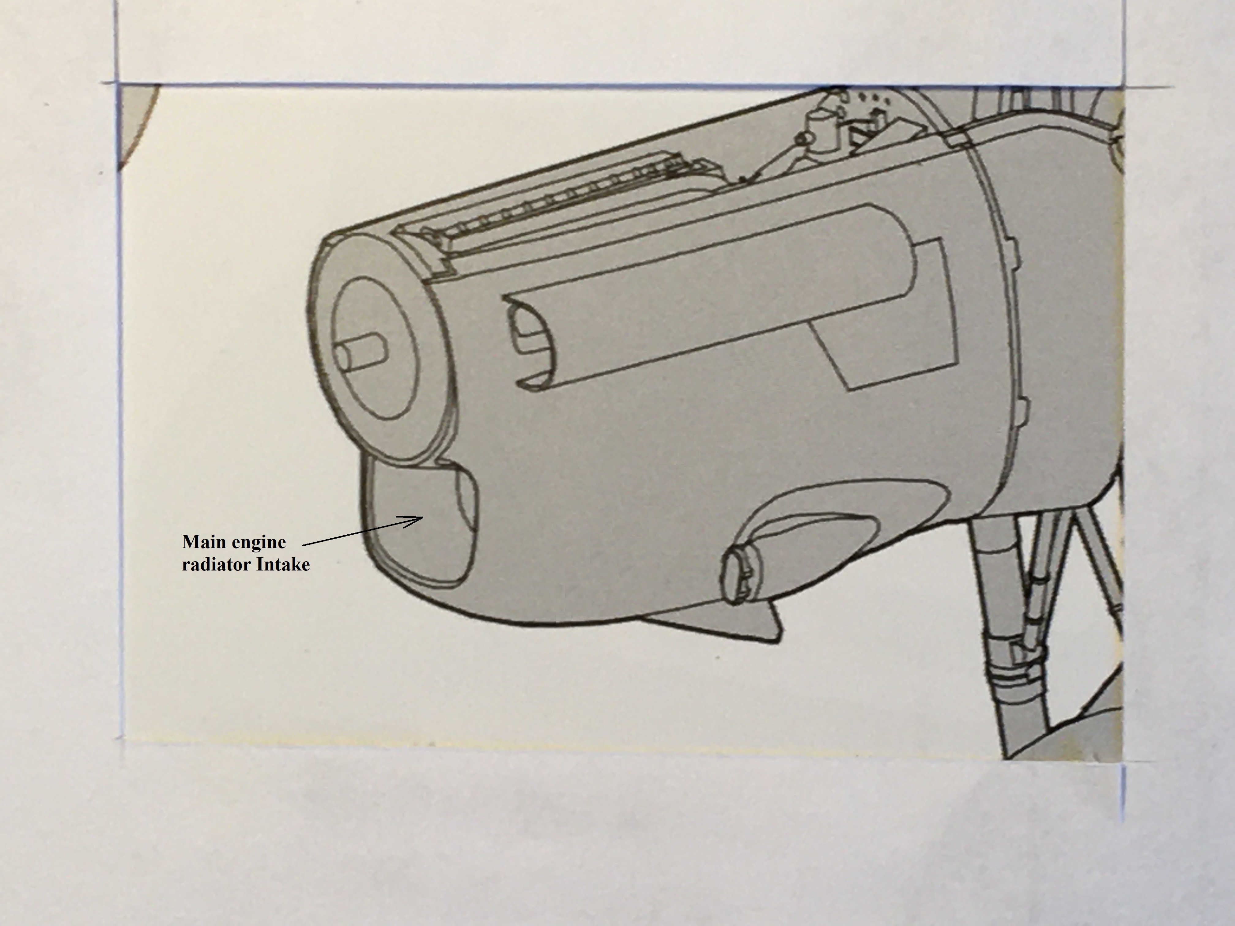
Kai You could glue the very front section that covers the radiator opening, once dried apply Mr. Surfacer, rub flat and IF all goes well one could scribe the 'new' angled vertical line(s) . . . . Just a micro-second thought Ian -
Lancaster ND644 in 32nd scale
FME erk replied to FME erk's topic in LSM 1/35 and Larger Work In Progress
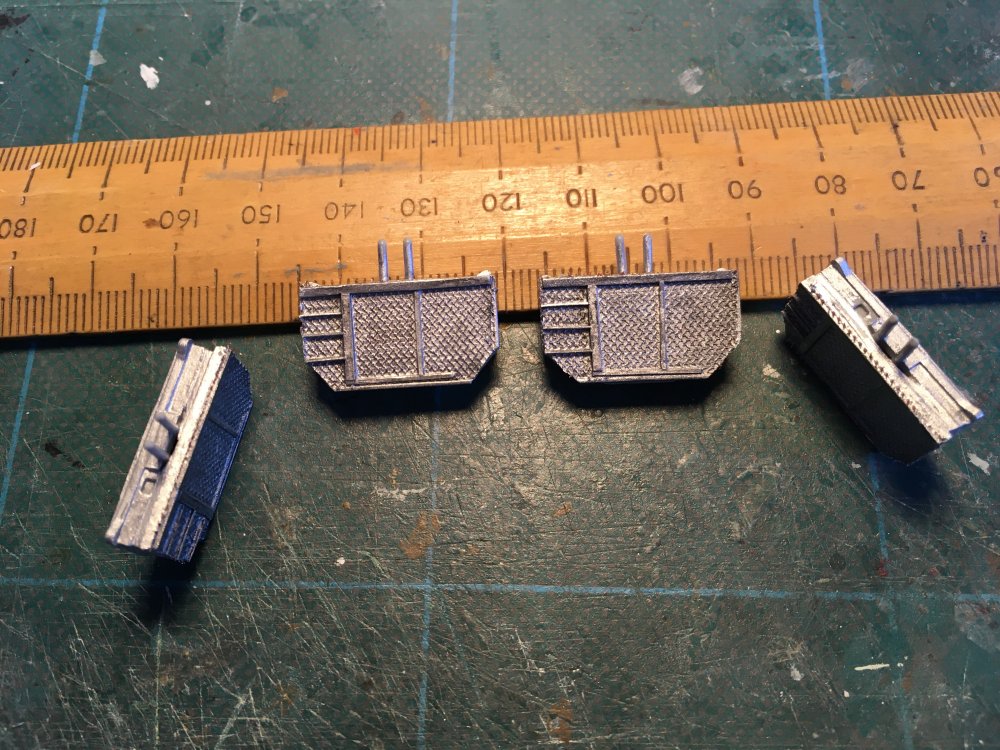
As I intend to have my rear entry door open - it only seems right to have the step correct . . . its only a small issue but needs correcting First pic shows the kit step and in particular the shape, I have seen this in 'Just Jane', NX611 Quick fix . . . . . . and the fact that I shall have the crew ladder in place will only draw attention to the entrance.thumb.JPG.50d260ba3b70a68996e8835bd3b2d3f4.JPG)
.thumb.JPG.ef64988dddac4d48aab823e585058789.JPG)
-
Lancaster ND644 in 32nd scale
FME erk replied to FME erk's topic in LSM 1/35 and Larger Work In Progress
Thanks for the update, its nice to know they did change something . . . . -
Lancaster ND644 in 32nd scale
FME erk replied to FME erk's topic in LSM 1/35 and Larger Work In Progress
Another error in the kit that could have been avoided if better care had been taken when doing the research . . The tailplanes: probably best described on Nigels Modelling bench, I think the only video that is still available, He states that he was not the one to discover the issue but he certainly was the one to rectify it so all credit to Nige. Basically HK molded the same to tailplanes Isometrically, there are two top pieces that fit on the port side, creating a top and bottom, which glue together and two bottom pieces that fit the starb'd side in the same manner. I have now carried out the modification . . . You can see the part numbers on the instruction sheet but when you alter the pieces you end up with the parts allocated thus . . . (see third photo) You will note the part numbers . . . differing from the instruction sheet . . . and finally we have a tailplane where there are inspection panels beneath both the starboard and port tailplanes I hope that its all as clear as mud . . . till the next time cheers Ian.thumb.JPG.59e63e3ee5ef580cfed326162c00bd82.JPG)
.thumb.JPG.677eba6b590f98e4ed88424eaf5195cf.JPG)
.thumb.JPG.e3a593638ffb3852c6366c849f0f861b.JPG)
.thumb.JPG.787c098a6a43a13f554c0770ab27697d.JPG)
-
Lancaster ND644 in 32nd scale
FME erk replied to FME erk's topic in LSM 1/35 and Larger Work In Progress
You make a good point Carl, if they just simply copied the kit legs then they too will be to tall . . . -
Lancaster ND644 in 32nd scale
FME erk replied to FME erk's topic in LSM 1/35 and Larger Work In Progress
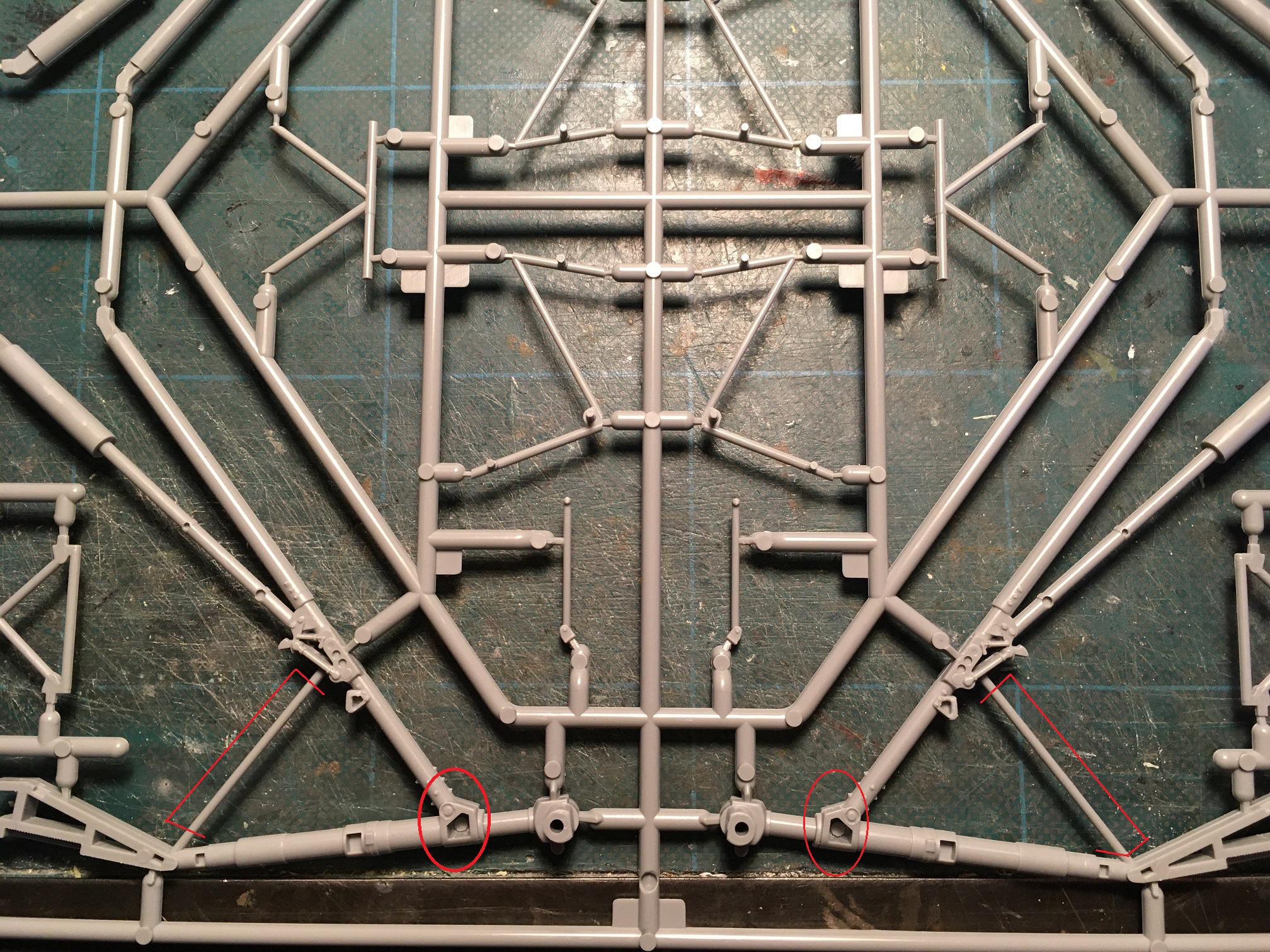
HK's main undercarriage legs have two 'holes' in the verticals yet on the real aircraft they are a solid cast. Why HK molded these like this is anybodys guess . . . After applying HK sprue glue to the undercarriage legs last Friday, I finally rubbed them down, still on the sprue, to obtain the end result . . . Thanks for looking in, more to come sooon Ian
-
Who could we possibly ask, to develop and produce some Hercules engines for the 32nd Lancaster ?
-
What Phil said, plus unbelievable attention to the detail . . Ian
-
Lancaster ND644 in 32nd scale
FME erk replied to FME erk's topic in LSM 1/35 and Larger Work In Progress
If only somebody was brave enough to create a 3D render and produce one for production . . . -
Lancaster ND644 in 32nd scale
FME erk replied to FME erk's topic in LSM 1/35 and Larger Work In Progress
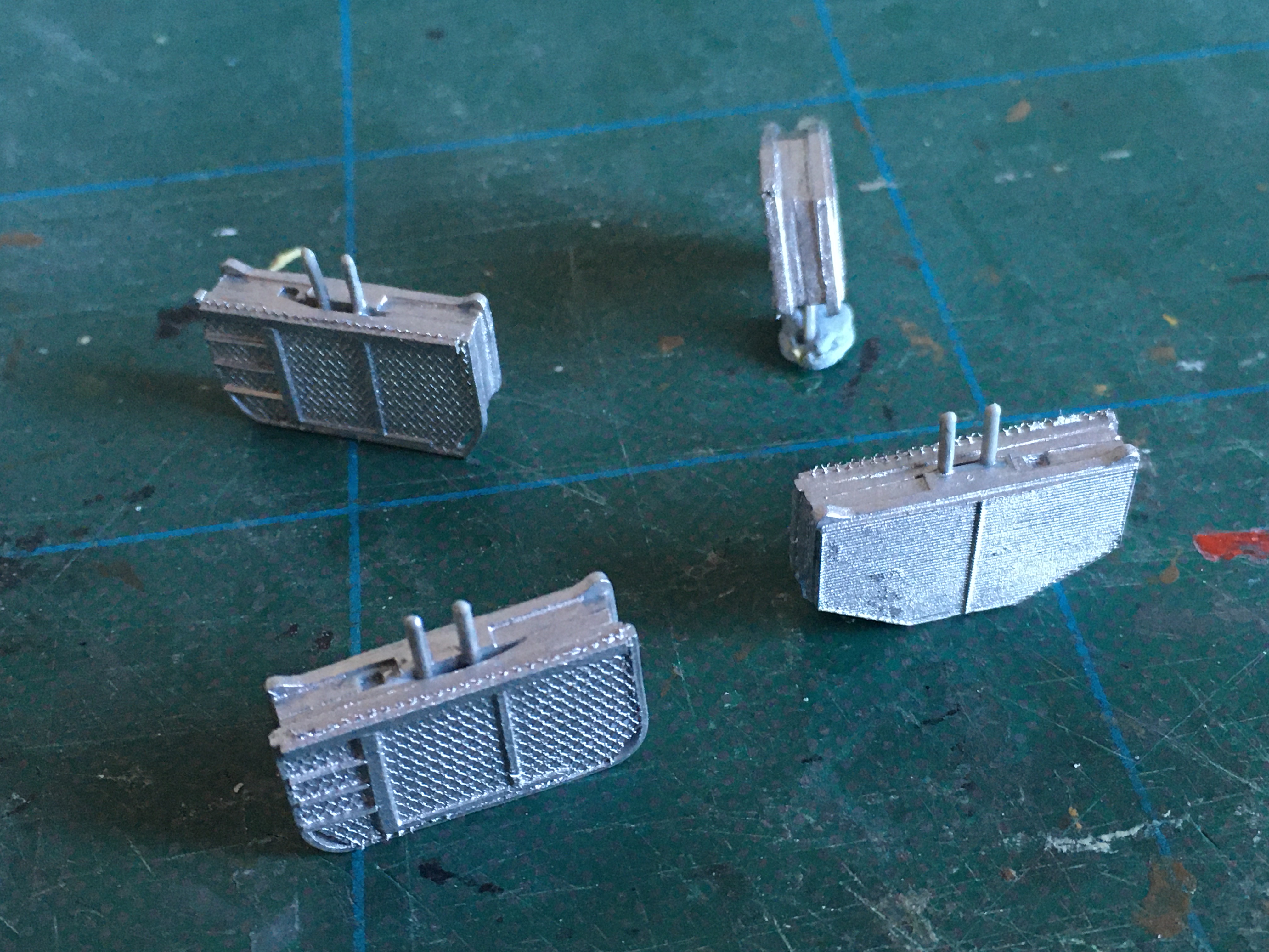
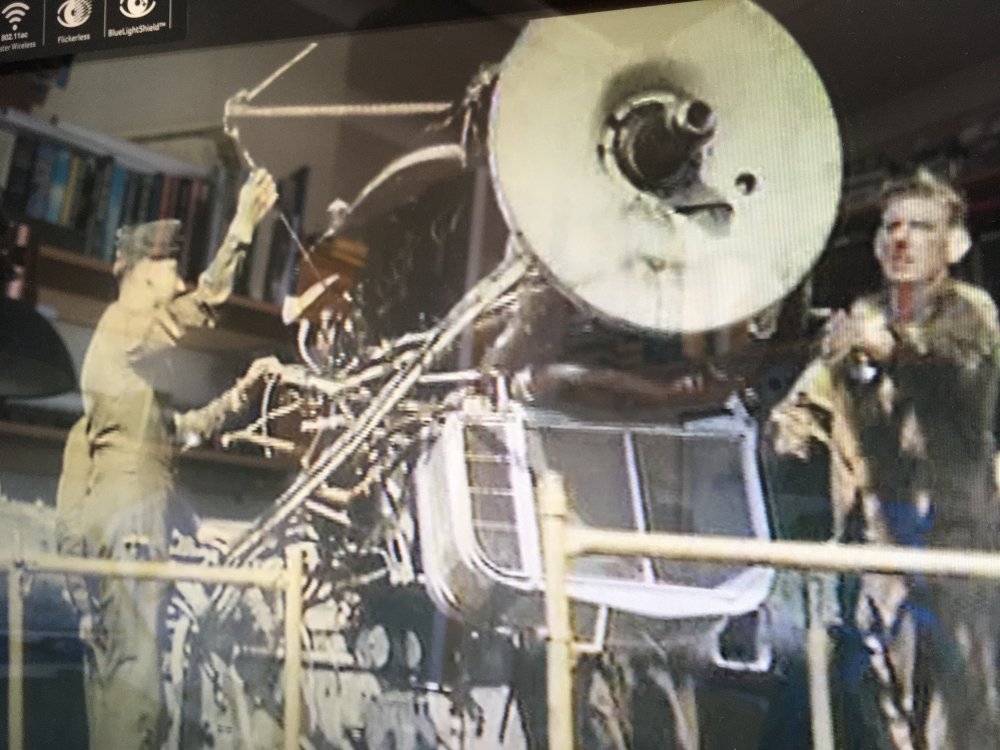
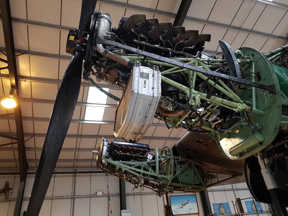
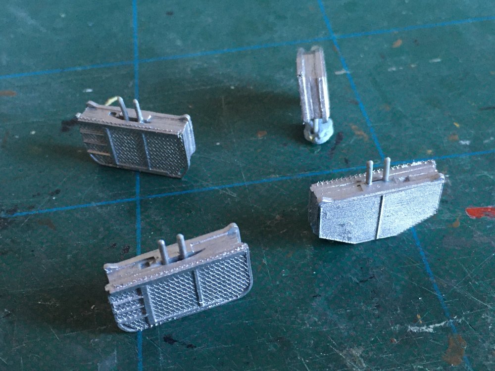
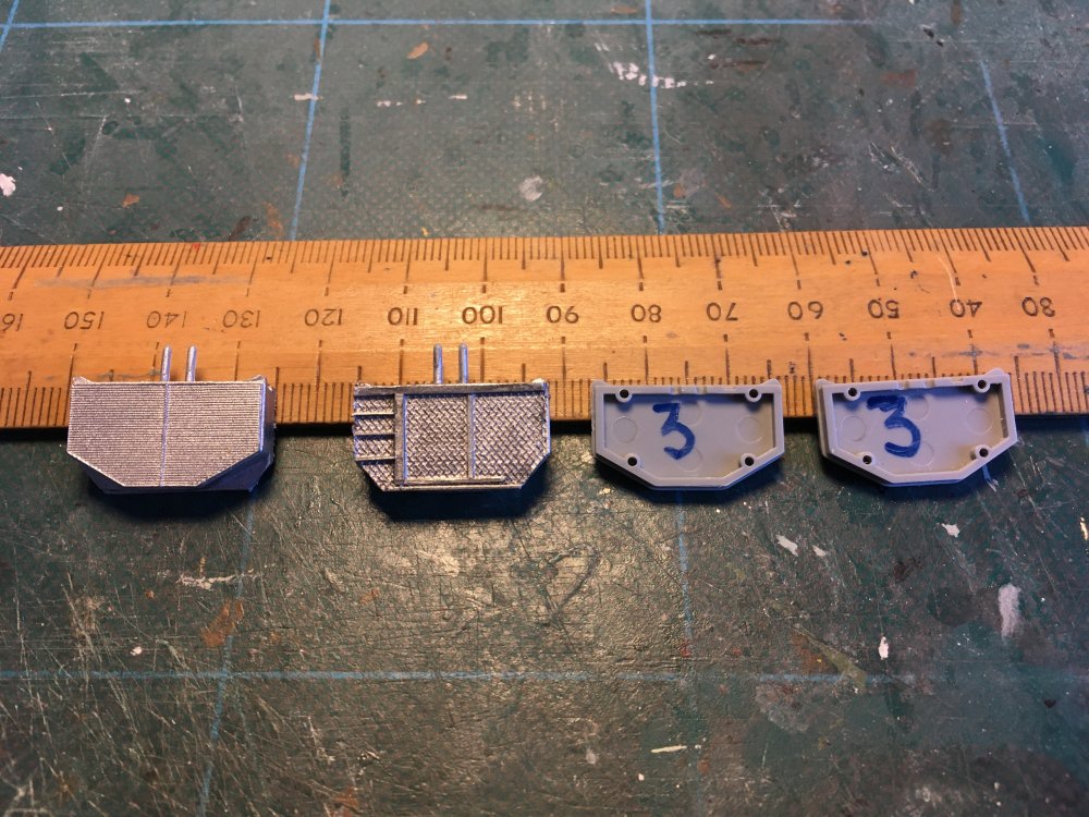
The next small change I have attempted are the engine rads that sit at the bottom of the engine and are viewable through front engine intake . . . The photos that Carl has posted show what looks to be a wartime pattern of radiator type. The kit radiator is a post-war type and that type only has two halves ie a single divide. Carls photo show THREE sections and the second photo shows the example taken from the film 'Night Bombers' Third photo shows the rad off 'Just Jane' with its two sections and the type molded in the kit . . . My attempts to replicate the 3 section radiator, probably a first for this kit . . . I didnt use the part No 3 from the kit and originally the bottom section of the rad was curved as in the wartime photo but It would not fit into the front cowl from the kit so was therefore cut at angles to fit in . . . Moving onto the next modification . . . hey ho Ian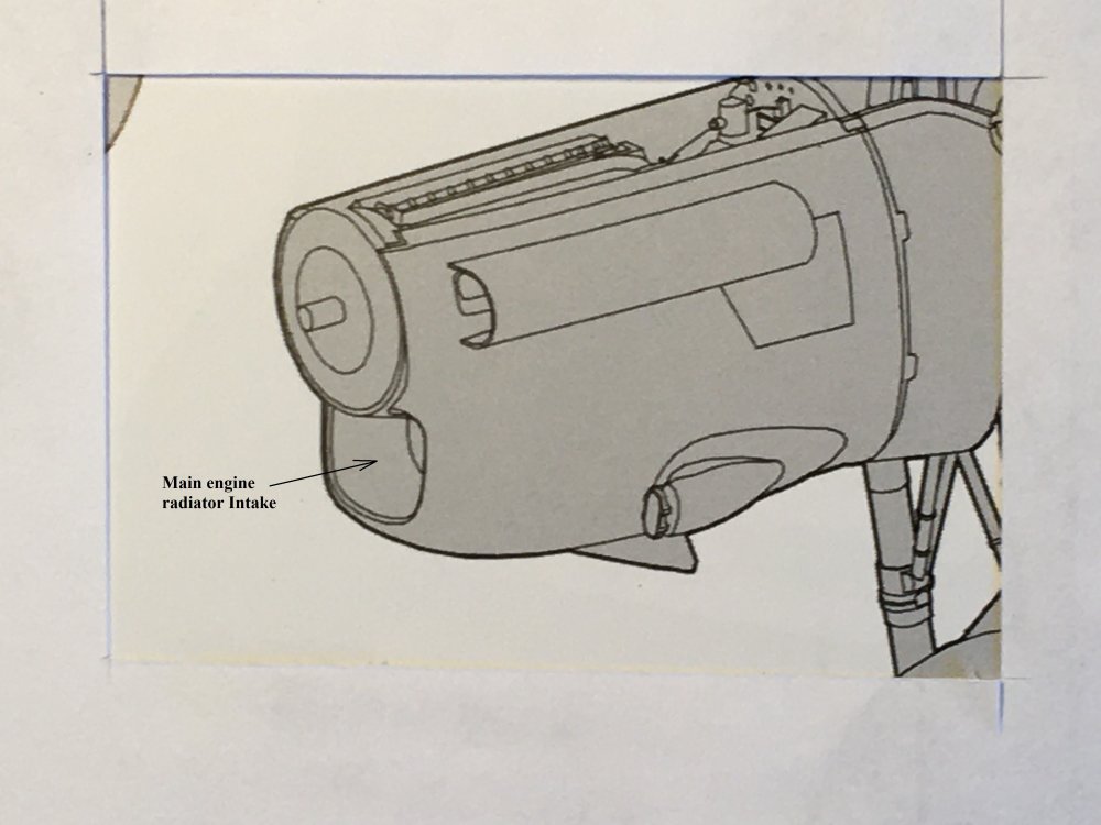
-
Lancaster ND644 in 32nd scale
FME erk replied to FME erk's topic in LSM 1/35 and Larger Work In Progress
Great photo Carl, thanks for sharing those . . . Certainly a lot of pipes and wiring to try and incorporate into the model Ian -
Lancaster ND644 in 32nd scale
FME erk replied to FME erk's topic in LSM 1/35 and Larger Work In Progress
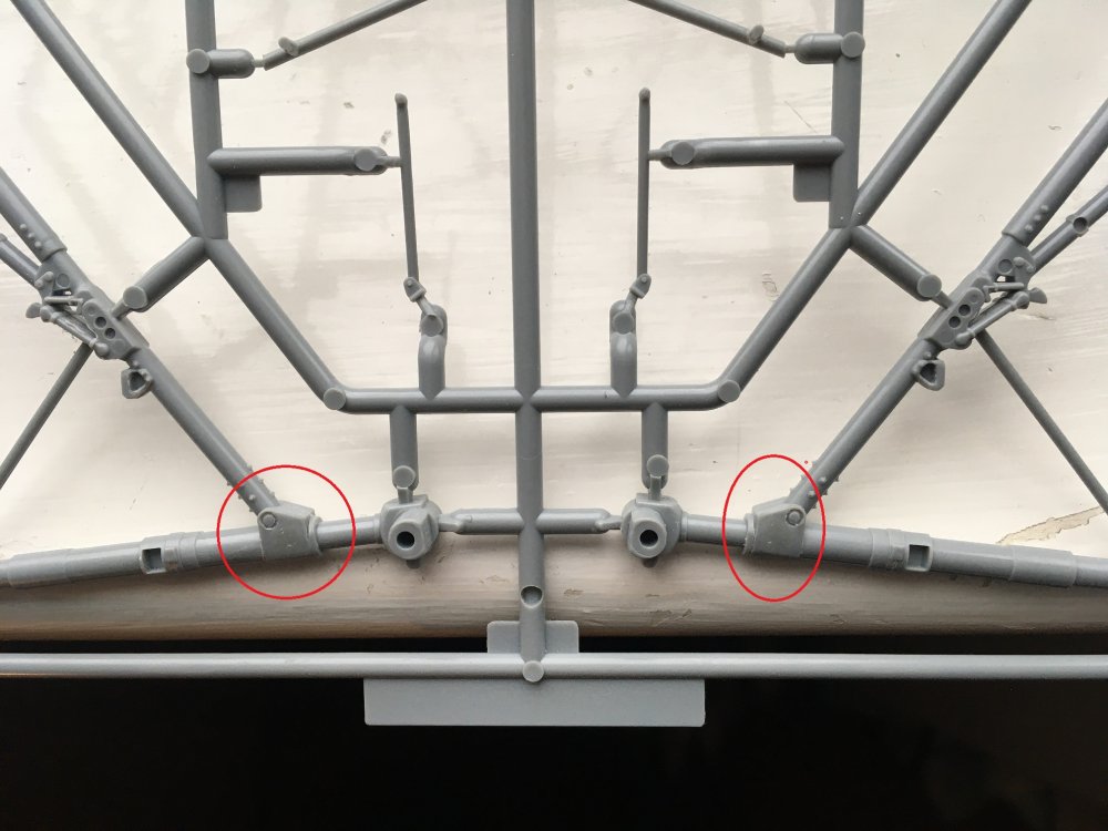
That clearly shows that when you build the model you should NOT be able to see the crossbar on the central brace . . . thanks for sharing that photo . . .
.JPG.e9a9ba56e470588e2f9e8c78bbcf71bf.JPG)
.JPG.36521f6639da07fa5411214e34dfaa0b.JPG)
.JPG.00cd555b3b717b4cdc00a3b538165324.JPG)

.JPG.9602a53df99ef6defdd4e5c34ab4a588.JPG)
.JPG.3ea9eb0faca2a83bcbd2e8c810c4230b.JPG)

.JPG.6e66b9583246e41722feded01b310882.JPG)
.JPG.66f068cc4fdb52f831155731a3fbbd08.JPG)
.JPG.524f2622368472ef745d309b3bf3bcd5.JPG)
.JPG.c9ed41c032b88165ae265d6bfd9d1896.JPG)
.JPG.df22645f49aa6566455a572d3abe621e.JPG)
.JPG.268108b000ed17c79f434f852c81b658.JPG)