Fidd88
-
Posts
196 -
Joined
-
Last visited
Content Type
Profiles
Forums
Events
Gallery
Everything posted by Fidd88
-

Frazer Nash FN5 gun-turrets
Fidd88 replied to Fidd88's topic in LSM 1/35 and Larger Work In Progress
Yes, I'm a member of the BMFA for my regular RX flying, but also of the LMA as the Wellington project is a much bigger airframe than they deal with, so I'm also a member of the LMA for design scrutineering for that project. We had a phenomenally busy Club Night here, with some 20 pilots turning up for flying - likely one of the last Wed Evenings that'll be flyable until the other side of Winter now, so everyone was having a last flit. I'll still be flying on the weekends, MET permitting. I need to get on with getting the Hurricane airworthy now, and start learning about FPV flight once I've got the measure of LOS (line of sight) flying the model in the normal way. This evening I drew up the proper exhaust stacks for the Hurricane - Dynam supplied me with ones for a later marque of Hurricane/Spitfire with the 6 stacks a side, rather than 3 (doubled) with the "fish-tail" end section. Not easy to draw. Pics to follow when printed and fitted. I need to buy a new TX, and a Crossfire unit for extended range, which should make the control connection to the TX bomb-proof at the ranges I'll be flying. It also bumps the video reception range to well over 4km without drop-outs. Being Digital video it lacks the extreme range of the older analogue jobs, but it's not legal to fly FPV beyond line of sight in this country, so much more than 1km isn't needed for this size of model. So my possibly erroneous understanding has established. Probably! By the by, I came across an very interesting youtube channel of a Texan model-maker, working in metal, who is currently producing a series of model metal-working machines - lathes etc. Amazing stuff, as it all works! I'd love to gave a small watch-maker's lathe/mill but there's no way I can afford it as well as other tools and materials I know I need for the Wellington. See: -
Frazer Nash FN5 gun-turrets
Fidd88 replied to Fidd88's topic in LSM 1/35 and Larger Work In Progress
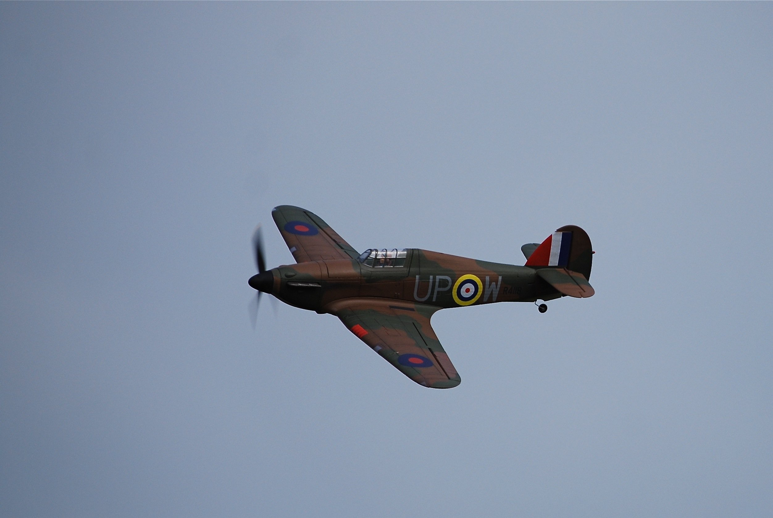
Hi all, The last few weeks have been busy on the RC flying side. I've done over 100 hours on the "Apprentice" with only one crash. I'd been getting more confident and doing aerobatics, and forgot to switch the control-defelection from high-rate to low rate before landing, which would give fine control instead of the rapid inputs required for aeros. I'd made a pig's ear of the approach and so went around in the normal way, however because of the rate still being high, the aircraft went suddenly vertical at about 15 feet, before executing a very pretty power-on spin-entry - and then ploughing into the ground. The engine-mount, fuselage and tail all suffered damage. After a couple of weeks I've replaced and repaired all the damage, and should be ready to re-maiden it tomorrow. I've also been building a Dynam Hawker Hurricane, which has flaps, retractable undercart, and should presently be able to carry a gimble mounted FPV camera. I'm getting some stencils made to paint all the roundels, (rather that using the stickers) and will be converting the insignia and letters to that of a 303 Sqn example. I've also added yellow prop tips to the 3 bladed prop, and will add "oil-leaks" and other weathering. Pics to follow in due course.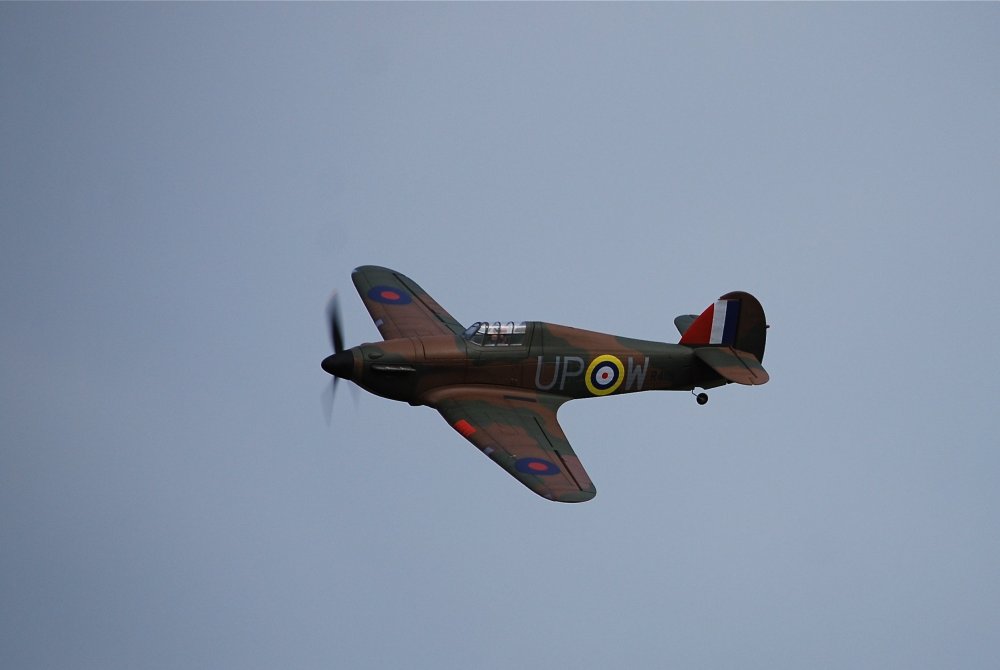
-
Frazer Nash FN5 gun-turrets
Fidd88 replied to Fidd88's topic in LSM 1/35 and Larger Work In Progress
Hi all, Lots of recent practice flying my little foam E-flite "Apprentice" - basically a Cessna 150/172 style high-wing monoplane, but with no operable flaps, undercart or variable-pitch prop. It has a wing-span of around 5 feet, and all the modern bells and whistles in the form of gyros, "panic buttons" and so forth that make learning so much easier these days. I've been flying 2-3 times a week, and can fly and land it even in strong gusty wind conditions without breaking anything although once in a while I have to throw an approach away rather than trying to rescue an approach that's gone pear-shaped. This is mainly because the landing patch is only half the size of a tennis-court, with high uncut grass of 3+ feet all around, so "landing long" just isn't an option. It's not unusual to hear a little whisper as the wings ever so lightly brush the tops of the high grass in the undershoot! Now that I've cracked landings, both into and cross-wind, I'm now conducting low and slow manouevering flights to really work on rudder and aileron coordination and accurate trimming before I start to look around for more complex model. At the moment I'm getting 10-12 minutes a flight, and reckon I should manage 14 minutes before the battery gets to 50%, if I don't hammer the throttle too much. Brilliant fun, but I need to get back in the workshop! -
Frazer Nash FN5 gun-turrets
Fidd88 replied to Fidd88's topic in LSM 1/35 and Larger Work In Progress
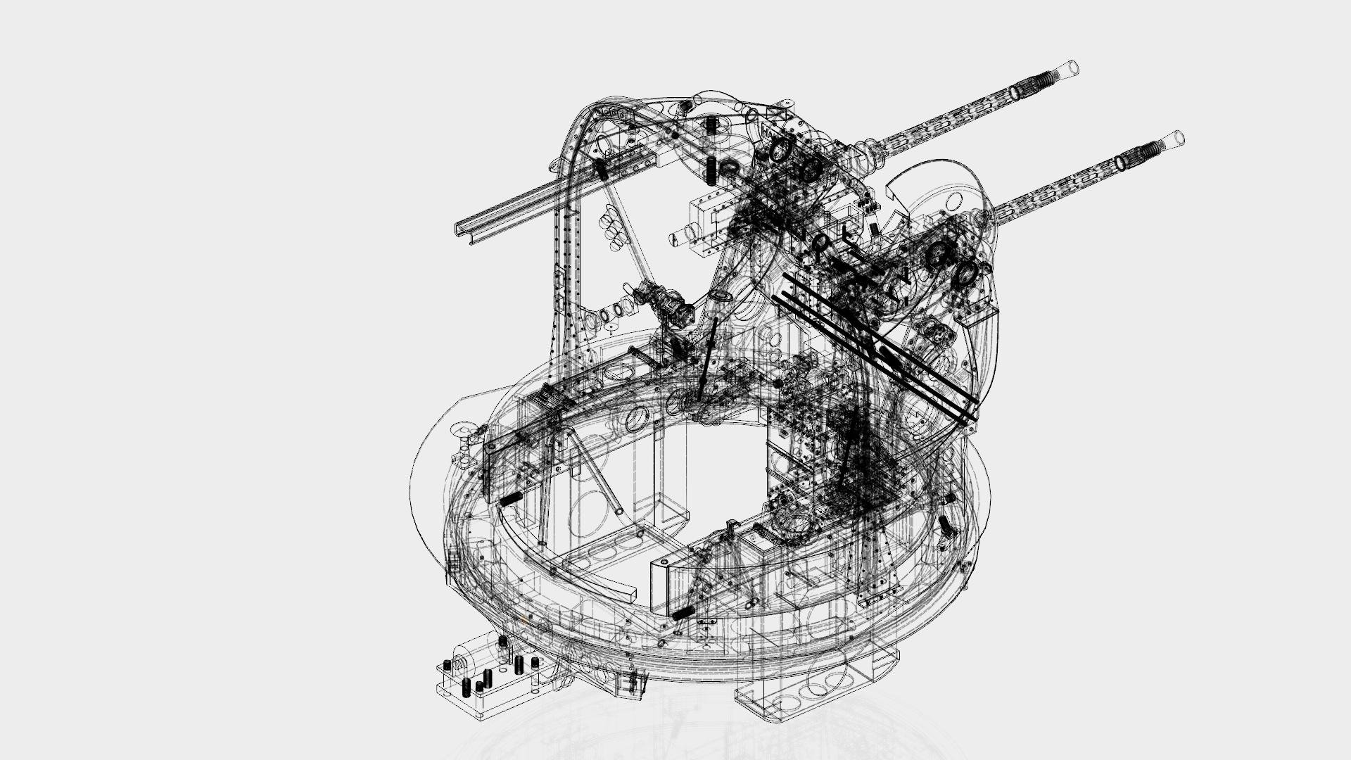
Crikey, my thanks, that's just made my day! It's nothing most people couldn't do. I taught myself to use Fusion 360 CAD early on, which allowed me to send .stl files to 3dprintuk, who then sent the "bits" back in the post. I then discovered that SLS Nylon, was both dimensionally very accurate, and crucially, could be tapped with threads down to M1 threads, allowing sub-assemblies to be screwed together, rather than glued. This has two benefits, it allowed for more efficient "nesting" of parts, which reduced the cost of printing larger parts, but it also allowed for the reversal of assembly if I got into a jam with the build sequence. This turned out to be vital, as in effect, it was akin to building a real turret, but with "4 foot long" screw-drivers, so tool access was a major consideration in the sequence of the build. Other than that, building them was fairly straight-forwards, other than making the compound-curved perspex panels for the cupola, to get the true shape of it. The other related problem was learning to draw compound curves in CAD, which was tricky. This meant that certain features such as the chordal brace stiffeners and the ammo feed-chutes were repeatedly drawn until they were got right. I never really managed it with the chordal brace stiffeners - the green structure that goes from the arch to the top of the main supporting silver side-piece of the turret. Fusion 360 can still be downloaded and learned for free, although with some functionality unavailable. Have a go! It takes around 2 months of practice and working through tutorials to get quick and accurate with it, and maybe another two months to really master compound curves. There's a very helpful set of forums if something defeats you... If there's anything you want to know more about, just sing out. My Youtube channel which has multiple films documenting the build can be found by searching YT for "Fidd88". I fear I'm no David Lean, and some are pretty dull, being made more to remind me than for public consumption, but some are interesting. -
Frazer Nash FN5 gun-turrets
Fidd88 replied to Fidd88's topic in LSM 1/35 and Larger Work In Progress
Last week was fun - I did my first flights with an RC aircraft, my little e-flite "Apprentice". Managed 5 flights, mainly circuit bashing, with no buddy-box, but a more experienced pilot next to me with timely advice. He gibbered a little, winced only a bit and hardly sobbed at all. I clipped a cow-slip in the undershoot on the 1st landing which span it into the long grass - no damage - and then pulled off 4 good landings thereafter. I had been practicing on the PC beforehand! I've since been flying a few times more, and am getting some consistency to my "circuits". Learned lots, had a complete ball, and avoided the "walk of shame" with a bin-liner of broken foam! (Loud cheers) I've also made a little progress on the Wellington front. My daughter's boyfriend is an apprentice-engineer like my daughter, and so I'd asked him to turn up a fitting for my rivet-gun suitable for these tiny 2mm rivets, which he supplied via #1 daughter today. It works beautifully, and I placed 5 rivets in a 1/2" sided square - like the dots on a die - through 2x 1mm plate alloy scrap. This enabled me to rotate the two sheets relative to each other to "work" the rivets to see if they'd fail. With a 9" mechanical advantage, and moderate force, I was able to loosen them, but it was something of an unfair test, as the mechanical advantage was considerable, acting on only 5 rivets. So I think they'll do. I've measured the witness-marks on the mandrels (the disposable shaft that snaps when you place a rivet), so can now get a 2nd tool made to place the rivets as deep as possible close to a perpendicular surface. This length of tool is a critical value, as it will greatly affect some design parameters. So, useful stuff occurring. I'm going to have to find a better way of de-burring after drilling, so that I don't eat away too much metal. A counter-sinking bit does a good job, but takes away fully half the metal on 1 sheet! :-( -
Frazer Nash FN5 gun-turrets
Fidd88 replied to Fidd88's topic in LSM 1/35 and Larger Work In Progress
So, some good news now. I've finalised the design of the geodetic channel, and now know how the internal fittings can be made. Hope this week to start the process of getting the alloy extrusions made. Once they're in, I can check the actual dimensional accuracy of them, and if needbe, change the dimensions of the CNC'd parts from which moulds will be made prior to casting. Then the CNC'd parts can be made, and the mould-making can commence, from which wax patterns can be cast. After that they can be investment cast to produce the required parts in alloy. They can then be drilled with the required holes, and fettled to fit into the channel. The next phase after that is making some small test-pieces, which I hope to get to by the end of the year. In parallel to this I'll be designing, building and testing the device for curving the channel to a specified curvature, and also a device for cutting the notches in each geodetic where one crosses another. This will be a 2 part operation, with two parallel cuts cut with an angle-grinder (thin cutting disc) in a jig restraining it's movement to achieve two cuts of exact depth and seperation. A special shaped tool (chisel) will then be used to press down on the channel to make the tapering portion of each cut. I'll probably acquire a small bench-top bearing-press, with some means of attaching the tool to the moving portion. The other thing under consideration at the moment, is to make my Mk IC Wellington an early example, still fitted with the unlamented FN25 "mid-under" (ventral) "dust-bin" turret. I may prepare drawings for it now, but a decision on building that may depend on funds, and the actual C of G position when the airframe nears completion, as it's well aft of the C of G, and these model turrets are not light. So, that's news for now! -
1/32 Revell Bristol Beaufighter build
Fidd88 replied to CrankyCrafstman's topic in LSM 1/35 and Larger Work In Progress
Hi, I know the collector-ring itself is steel, ie the ring into which exhaust gases are collected from the exhaust manifolds. What's less clear, is if the shroud containing the ram-fed cooling air is an alloy or steel. Looking at the Brooklands Wellington, it certainly appears to be alloy, but still might be this steel. The corrosion in the Beaufighter ring pictured in thread, does suggest you're correct though. Next time I'm at Brooklands I'll place a magnet on it. -
1/32 Revell Bristol Beaufighter build
Fidd88 replied to CrankyCrafstman's topic in LSM 1/35 and Larger Work In Progress
Excellent post, it's great to see some colour pictures of them. I can't speak to the Beaufighter, but I'm fairly certain that on the Wellington, these Townsend Rings are a steel inner-collector-ring, taking the hot gasses, with an alloy shroud around it, which is fed with ram-air, thus cooling the exhaust gases before they're emitted, which reduced both flame-flare and noise. That said, your picture appears to show corrosion on them more consistant with very thin steel on the hotter external (radially) portion of the ring, which does cast into doubt, my assumption that they were alloy. Perhaps one of us could quietly slip a magnet onto one when museums reopen?! -
1/32 Revell Bristol Beaufighter build
Fidd88 replied to CrankyCrafstman's topic in LSM 1/35 and Larger Work In Progress
I also would highly recommend Fusion 360, even though some features that were previously available on the free hobby use version have recently been rescinded. -
Frazer Nash FN5 gun-turrets
Fidd88 replied to Fidd88's topic in LSM 1/35 and Larger Work In Progress
I know! I spent some time talking to some of the chaps that did it, with a single hundred plus year old fly-press - and some determination! Talk about patience! You could have bottled my expression and sold for thruppence a time, once the full horror of building it thus sank into my conscious! Blimey, but that was a labour of love! My planned method looks positively Henry Fordesque compared with that - tiny movments at a time, and then drifting out the wood blocks afterwards. Crikey! The found a better frame 50 bulkhead (the one to which the trailing edge of the wing and aft end of the bomb beam attaches to) that some old boy donated to them - he'd been using it since collecting it in a scrap-yard at the end of the war - in his home-made greenhouse! Brooklands bought him a new greenhouse! -
Frazer Nash FN5 gun-turrets
Fidd88 replied to Fidd88's topic in LSM 1/35 and Larger Work In Progress
Cheers! The issue with the rolling-machine making the channel is not difficult about the cross-section, it's curving the geodetic during that's the complex bit. Hence my decision to extrude first and curve after. Which, incidentally, is how the missing geodetics on R for Robert at Brooklands, was made. I'm not a trained engineer at all, I worked in a motorcycle workshop years ago, rebuilding engines and servicing, so I've a little mechanical common-sense, and an O level in technical drawing from 40 years ago - indeed initial drawings for the turrets were pencil on paper at a drawing board! I just pick-up new skills from youtube, and if I collide with an immovable obstacle, just ask for help! Professionally, I was a commercial flying Instructor, teaching lads to get through their GFT's on light aircraft, which gives some familiarity with the flying side of the project, although 20 years after the car-crash that terminated my flying career, I've forgotten a LOT! You're correct that a side-mill might do the job, but without trying it, I'm uncertain of results. I'll go with whatever is fast, tolerably accurate and endlessly repeatable. A CNC mill is actually, in my experience a Royal PITA, as they'll decline to work as you might wish, out of sheer bloody spite! -
Frazer Nash FN5 gun-turrets
Fidd88 replied to Fidd88's topic in LSM 1/35 and Larger Work In Progress
Hi lads, I can't tell you how brilliant it has been to get some encouragement at this juncture in the project, as well as going through a divorce after 26 years - the Wellington seemed stymied at every turn, and has been really hard to keep up the enthusiasm for it in the face of difficulties with the riveting, and then insane quotes for things I'd assumed - my error - would not be overly dear. I really needed some encouragement to get past this point, as the difficulties expenses and technical problems were seemingly stacking-up faster than I could deal with 'em. So THANKS! Much appreciated! -
Frazer Nash FN5 gun-turrets
Fidd88 replied to Fidd88's topic in LSM 1/35 and Larger Work In Progress
Some better news. I've had some assistance from some of the other RC chaps who've suggested using CNC to make a small number of these fixings, and to use them to make a mould from which wax positives can be cast and attached on a suitable wax sprue. These can then be investment cast in alloy, in numbers, and machined/drilled/ground as required after the casting. Which puts it financially at least, back on track, and I get to learn some more skills! I've also had the offer of a loan of a small forge, which is both kind and hugely good for morale! I'll also be looking into a different form of casting on a commercial basis, to see if a better result can be achieved within an affordable price. -
Frazer Nash FN5 gun-turrets
Fidd88 replied to Fidd88's topic in LSM 1/35 and Larger Work In Progress
Hi all, More news on the Wellington project - but not "good" news. I'd budgeted around £1000 to have the two types of solid internal fittings for the geodetic joints, as shewn in the film above, and found a company in China who were able to undertake the work. When the quote came back it was (for 13,000 fittings) over £17,000! Which is a complete show-stopper if I can't work around it. I'm currently investigating making the "butterfly" and "wishbone" joints by folding flat sheet cut to shape - which is a much cheaper proposition to have done, but may be problemtical in practice, and may do the job. Both are also possible to make from an extrusion, milling the shapes one at a time, to create the finished parts. Needless to say, this is not my preferred method as extrusion die tooling costs are not trivial. In the meantime I'll be seeking more quotes in case the 17k one was an outlier. Not a happy bunny. -
Frazer Nash FN5 gun-turrets
Fidd88 replied to Fidd88's topic in LSM 1/35 and Larger Work In Progress
After a couple of days at the pc the two main joint-types for the alloy "basket" which forms the fuselage and wings of a Wellington have been drawn up to ensure I can get all the internal metal fittings made before the extrusion die tooling costs are paid. -
Frazer Nash FN5 gun-turrets
Fidd88 replied to Fidd88's topic in LSM 1/35 and Larger Work In Progress
Not much news, but at last a little progress. I've got a mate to turn up a rivet-gun tool-tip for placing the 2mm diameter rivets, with a long enough reach to place them in the majority of the "ordinary" geodetic joints. All 16 rivets and 2 machine-screws with nuts per single joint! I haven't counted all the joints on the Wellington, but I expect to use well over 20,000 rivets on the whole airframe. I'm now redrawing all the joint fixtures and fittings, and the profile of the channel, as well as the inserts used to prevent the cross-section collapsing as it is curved. Have now decided to use small o-rings, or possibly small rubber washers, to place between the 1mm thick metal inserts which will exert forces from the steel cable on the geodetic channel to effect the curving. Pics to follow in due course when there's something to show. This whole rivet-tool-tip problem has taken months to resolve. I'm now facing a series of things that need sorting out in a very particular sequence, so I commit the least money possible in each phase until I'm sure the whole thing is feasible. -
Lancaster ND644 in 32nd scale
Fidd88 replied to FME erk's topic in LSM 1/35 and Larger Work In Progress
No problem. It always amazes me the breadth of knowledge in forums such as these, this was just one I happened to know a bit about. I can't remember what groceries I need - but this sort of stuff just seems to stick in my memory! Lord knows why... I forgot to mention that such gas-indicating paint was also applied to British field-guns, trucks, tanks and much else from the pre-war period until 1941, until it became evident we'd not all be clobbered with this muck at the outbreak of war. The "Keep Calm and Carry On!" poster is thought to have been designed to be read wearing a gas-mask. It was never actually issued in war-time, as it was expressly meant to be put up in the aftermath of a gas-attack. As the Bari incident shows, there was still considerable preparation for retaliatory chemical warfare in anticipation of the Germans resorting to it as the Third Reich began to collapse. Probably the only thing that prevented it, was the Germans lacked the delivery capability in long range bombers that the allies possessed. Just as well really. -
Lancaster ND644 in 32nd scale
Fidd88 replied to FME erk's topic in LSM 1/35 and Larger Work In Progress
Yes. It would have reacted to Mustard, turning from a yellowy zinc-chromate colour to pink in it's presence. It may also have been reactive to phosgene. As the German stance on using chemical weapons was unknown at the outbreak of war, but they'd been enthusiastic exponents of chemical warfare, in the Great War, the RAF was fully ready retaliate with mustard, were the Germans to use it first, and It was likely as much to indicate contamination from our own gas ordnance as enemy chemical attacks. Bombers carried circular indicators, around 9-12 inches in diameter, usually (but not exclusively) on the upper tailplanes, starboard side. Fighter aircraft has square indicators, usually on the port wing arranged so that the diagonal of the square was aligned with the chord line of the wing, again on the upper surface. By mid '41 these had largely disappeared from RAF aircraft. Similar patches can be found on RAF vehicles of the period. Such preparedness on the part of the allies was evidenced by the disaster at Bari in December 1943 when it is thought several ships carrying mustard were sunk in flames at the harbour. Bari disaster -
Frazer Nash FN5 gun-turrets
Fidd88 replied to Fidd88's topic in LSM 1/35 and Larger Work In Progress
Hi all, I trust you're all keeping out of the path of this bloody virus? I was not surprised today when the British PM "cancelled Christmas" by doing away with a 5 day relaxation of the rules to enable us to get together. People just don't get it. We're in the fight of our lives against this damn bug, and being able to get together or go to the pub or whatever must come a very distant second to keeping the infected people requiring treatment below the point where our health services cannot cope - or else we'll cop for it like the Italians and New Yorkers did with mass-graves and much higher fatality rate. I get so cross with people who lack the understanding or sense of duty that we simply must do everything possible to help each other, and help out doctors and nurses, until vaccinations can batter it back into some form of normality next year. My brother's a MD (Doctor) in the US, who has just had his first days off since March, having worked 7 days a week continuously in ICU since it hit. The stuff he tell's us about what he thinks about people who won't wear masks, or get vaccinated is blistering in it's raw anger, and he's not someone usually given to "anger". Rant over. (apologies) So, my daughter and I are spending Christmas alone, as we'd intended to even before it was "cancelled". Regarding the Wellington: I'm still hung up on the rivet-tool decision, which makes progressing with the CAD or production of extruded alloy channel impossible. I'm dealing with the UK supplier of an American manufacturer of rivet tools, so everything takes twice as long. Looks like mid-January now before that log-jam can be broken. Instead I've just finished reorganising the workshop so that there's room for the "bending device" to operate on the right-hand end of the bench, and I'm also busy making lots of rough drawings of how the bending device will operate. Not quite there yet, but close now. The changes in the workshop also allow the jig to turn without colliding with the nuts and bolts storage. Latest changes -
Frazer Nash FN5 gun-turrets
Fidd88 replied to Fidd88's topic in LSM 1/35 and Larger Work In Progress
Hi chaps. What with Covid, and it's effect on lots of companies, I'm struggling a bit to make progress at the moment. The rivet tool company I'm working with are having difficulties determining the tool-head to use to apply these very small (2mm diameter) pop-rivets. Until the tool-heads size is known, I can't do the CAD to finalise the extruded alloy profile or the sheer and gusset fittings, or the inserts needed to curve the extrusions. So, instead, I've been having a clear-out and reorganisation in the workshop to gain more space to the right of the bench, which I'll need for operating the device I will build to curve the channel without deforming the cross-section. Here's a film of changes to the workshop and my "patent" peg-board and shelving. which I find a really flexible storage system; and, a quick look at the two types of joints on the airframe. -
Frazer Nash FN5 gun-turrets
Fidd88 replied to Fidd88's topic in LSM 1/35 and Larger Work In Progress
I'm unable to work these days - legacy of an old car-accident, so have decided to see if anyone wants one of these models, and is prepared to pay to have one built. To that end, I've put "commissioning one" onto Ebay to see if there's any interest. As they take 5-8 months to build and paint, and thousands of pounds to print all the parts to the required finish and dimensional accuracy, these are far from a cheap model to build. If I get a lot of interest I may look into getting parts injection-moulded, which would bring the per unit cost down, but raise the initial tooling costs. The item number on Ebay is 184506409292 or here: Ebay auction to start commisioning process I'm hoping, if I get a commission, to plough the funds back into the Wellington project, which fairly eats money! I should emphasise, this is not posted out of any expectation that anyone here would want one at this price! -
Sd.Kfz.221, Unknown Unit, Sovereign 1/35
Fidd88 replied to Rodolfo Torres Vazquez's topic in LSM Armour Finished Work
Thanks for posting those, quite comforting to know he's not perfect! Nice job capturing it correctly in the model! -
Frazer Nash FN5 gun-turrets
Fidd88 replied to Fidd88's topic in LSM 1/35 and Larger Work In Progress
I'll try and answer this again. Lets say our fuselage was cylindrical, and there are no longerons to complicate matters. If we cut through the cylinder at 45 degrees, we end up with the cut face of the solid-cylinder being an ellipse. So, if we make a solid flat ellipse of the same size, and wind a soft-metal shape around that ellipse, when the resultant elliptical alloy channel is fitted at the correct 45 degree angle, the internal space will be circular again as viewed from the end of the cylinder. The same principle holds true if our cylinder tapers, only now the start-point of the channel must be the same as the point on irregular but roughly ellipsoidal (ovoid) path, in order for the taper to appear smooth and not irregular. As the required former shapes (our ellipses in the example above) are easily derived from slicing a solid 3d shape, it follows that provided the initial 3d shape is correct, so will the shape of the eventual metal-basket of geodetics be. As for actually bending the extruded channel. Inside the channel is a steel cable, of 2mm diameter, which has a breaking strain of circa 250kg. Threaded onto this are metal plates, and hard rubber plates, alternating in sequence, fractionally undersize to the internal cross-section of the extruded channel. On one end of our cable we attach to a 230kg weight on the floor. The other end attached a point on the wooden elliptical pattern laying flat. The pattern has an axle though the middle, and a ratchet mechanism, so that as the ellipse is rotated the extruded channel has to conform to the ellipse, via considerable forces exterted by the weight now being lifted off the floor, and transmitted to the channel via the alternating hard and soft plates and the steel cable. The result is dependant on the thinness and number of said plates, but should theoretically, create a geodetic channel of the correct curvature via hundreds of slight bends, but once the cable and inserts are removed, with a cross-section which is largely undeformed. Phew. There's a lot to do to get to that point, but it's the only way I can see of achieving it after 7 years studying the problem. If you have other ideas please let me know! -
Sd.Kfz.221, Unknown Unit, Sovereign 1/35
Fidd88 replied to Rodolfo Torres Vazquez's topic in LSM Armour Finished Work
Interesting geometry on those doors. I've never seen a picture of one with the doors open, but I'd have expected the fully-open door position to be the lowest point of the door to be inline with the hinge-line - where it couldn't exert any further force on your hand if it were trapped between the door and items on the outside of the vehicle. A "stop" is also usually fitted to prevent the door or hatch opening beyond that point. As an ex-"tankie" you tend to value little design features like this, as the number of ways you can lose/crush/cut-off fingers/feet and heads on any armoured-vehicle are legion, and bad-design abounds. As Jerry is a good engineer, this looks like an uncharacteristic oversight for him, bless his little Hun-heart. Anyone seen a photograph of one with the doors open? -
Frazer Nash FN5 gun-turrets
Fidd88 replied to Fidd88's topic in LSM 1/35 and Larger Work In Progress
Well I'm just back from the rivet-gun shop (more of a factory really) and the absolutely brilliant news is that the tool will fit on the gaps I have to work within on the current dimensions. They even gave me a tool nose to take home so I can draw it up in CAD and play around with it. That means a lot less work potentially! - And building stuff sooner! Loud cheers!