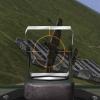
Trigger Posted May 9, 2021 Author Posted May 9, 2021 Hello guys, time for a small update, Started on the gun deck, removed all unnecessary objects that do not belong on an e model. Put the leather "bag" in place that houses the wiring for the instruments. lengthened the gun deck so it can house the ammunition boxes, scratch build the housing, Also installed some wiring for the interrupter gear an a few Electra boxes masked everything and sprayed it in RLM02 painted the wires and the leather bag in front of the cockpit Did some plumbing, a tank fitted and the the hoses to the tank Well, that is it for now, next step is to scratch build the lower firewall so I can get the engine mounts in place, Cheers, Frank 7
Kaireckstadt Posted May 10, 2021 Posted May 10, 2021 Beautiful progress and everything looks spot on! The leather cover looks really convincing as does the plumbing and the tank. Is this the Tamiya RLM02? I‘m curious to see your scratchbuilding of the lower firewall. 4
GazzaS Posted May 11, 2021 Posted May 11, 2021 Very nice looking work! Love the leather bag! 9 hours ago, Kaireckstadt said: Is this the Tamiya RLM02? That looks like Tamiya 02 to me. What 02 do you use? I usually lighten it quite a bit. 5
Peterpools Posted May 11, 2021 Posted May 11, 2021 Frank Fantastic - amazing work as always. Keep ‘em comin Peter 4
Trigger Posted May 11, 2021 Author Posted May 11, 2021 11 hours ago, GazzaS said: Very nice looking work! Love the leather bag! That looks like Tamiya 02 to me. What 02 do you use? I usually lighten it quite a bit. You are right, it's Tamiya XF22, i only thinned it by approximately 60%, sprays nicely then and less, tip drying. It does seem bit on the dark side, but whatever foto's you study, the only reference material are all restored aircraft, so for me this works well , thanks for the response Gazza, Frank 4
Trigger Posted May 11, 2021 Author Posted May 11, 2021 20 hours ago, Kaireckstadt said: Beautiful progress and everything looks spot on! The leather cover looks really convincing as does the plumbing and the tank. Is this the Tamiya RLM02? I‘m curious to see your scratchbuilding of the lower firewall. Hai Kai, yes that will be interesting, the lower firewall bends inwards with a rounding so it will be a challenge, but I need to get it done otherwise the engine won't fit, so say tuned...... Frank 3 1
Trigger Posted May 14, 2021 Author Posted May 14, 2021 Hello Guys, here's another update on the ME109, I first assembled the engine as far as I could to test fit it in the fuselage. Had to fill in the holes of the spark plug housing, on the DB605 there is only one hole per 2 spark plugs, but on the DB601 each spark plug has it's own hole, so I filled in the holes and drilled new ones, And made a tube for the ignition wires and placed the ignition wires Then I fitted the fuel pump and fuel lines Fitted the upper supports for the engine bearers , and test fitted it to the fire wall With a ruler on top, fits nicely HPH made those bearers with a metal pin inside, so fitted a copper tube to the fire wall so the engine bearer could slide in to place easily Started to scratch build the lower part of the fire wall and sprayed it in RLMO2, so that is it for now, more to come, Cheers, Frank 10 1
Kaireckstadt Posted May 15, 2021 Posted May 15, 2021 Stunning progress Frank! The work you did on the engine and the firewall is really awesome. Is the tube you used for the ignition harness Evergreen round profile? Curious how this will go on! 3
GazzaS Posted May 15, 2021 Posted May 15, 2021 I can only echo what Kai says. Really great progress! 4
Trigger Posted May 15, 2021 Author Posted May 15, 2021 7 hours ago, Kaireckstadt said: Stunning progress Frank! The work you did on the engine and the firewall is really awesome. Is the tube you used for the ignition harness Evergreen round profile? Curious how this will go on! Hi Kai, the tube for the ignition harness is indeed evergreen tube (hollow), the tube from the kit wasn't suitable because of the other spark plug arrangement on the DB601, I am now , (once the firewall is all done) , trying to get the diagonal motor supports in place so I can line up the engine with the cowling, and the engine is able to carry it's own weight, I might just have to replace the original struts by copper tubing because of the weight, anyway lots to do, the Mirage is now very close to painting, it must be motivating to know that you are almost there, the hydraulics of the undercarriage look spot on! Cheers, Frank 2
Peterpools Posted May 15, 2021 Posted May 15, 2021 Frank Fantastic progress ... your attention to the smallest of details is amazing. Keep 'em comin Peter 2
Trigger Posted May 24, 2021 Author Posted May 24, 2021 Hello Guys, Here's another update on the 109, started with the engine mounts and the lower struts, placed copper bushings in the firewall so the lower struts would fit nicely and solid, (used epoxy), then I had to line up the engine so it was horizontal with the gun deck and would still fit inside the cowling. Had to cut up the nose into a lower and upper section, because I want to show the engine, the lower cowling needs another cut, so you can see the oil cooler. Build the oil cooler from scratch, the front and rear radiator mesh were the only things I could re-use. First I have to dry fit the coolant lines from the cooler in the front to the firewall, beneath the cooling lines the oil cooler is situated hanging from a bracket attached to the cooling pipes. (on the later G models they mounted the oil cooler in the lower cowling, on the right side was a hinge so you could let the lower cowling swing to one side complete with the oil cooler) On the E models this is not the case, the entire lower cowling has to be removed to get access to the oil cooler. So her are some pics, The engine bearers the right one still had to be lined out to be even with the left side, did some work on the engine and painted it black and put some scratch build details on. The engine is now hanging on the engine bearers like the real plane this is what holds everything together the coolant reservoir, painted and some cooling lines added Scratch build a bracket that is only present on the E models This is the idea how the oil cooler should be place, I must make a bracket that goes from left to right and supports the cooler, the whole thing will be hanging on the cooling lines, the cooling lines are attached to the rocker cover as you can see on the picture below. The upper and lower cowling cut in half, the lower cowling must still be cut up a bit further. after cutting I will smoothen the surface, there is a lot of polyester and resin to be removed It's all very time consuming because you basically have to scratch build a lot of items , like the oil cooler and some bits and pieces on the engine, also scratch build the throttle controls and mounted them to the fire wall, with a rod going through the side wall on the left so that's it for now, it doesn't seem much but you really need to think twice before you cut something up, cause there's no way back. and a lot of research and looking at pictures where everything is fitted. So, Until the next update, Cheers, Frank 8 1
Kaireckstadt Posted May 24, 2021 Posted May 24, 2021 Really awesome progress on your 109 Frank! I can imagine that it is a lot of work and your scratchbuild items look just perfect! This is really a big challenge you have to face because it is as you said: once a decision is taken there is hardly no way back. But up to now you faced it perfectly! Curious to see the next update! 5
GazzaS Posted May 25, 2021 Posted May 25, 2021 Loving all of your scratchbuilding! Love the little details... and the fact that the engine hangs on the bearer! 4
Peterpools Posted May 27, 2021 Posted May 27, 2021 Franks fantastic work and your scratch building abilities come shining through on how you hung the DB in the engine bearer. Keep 'em comin Peter 2
Trigger Posted June 19, 2021 Author Posted June 19, 2021 (edited) Hello Guy's, time for an update on the 109 I was working on the engine, but decided to put my attention to the fuselage, because once the engine is in place it becomes very tricky to handle the entire plane, and the fuselage also needs a lot of work, and I don't want to knock of the engine by accident. So first I will do the fuselage, I have begun to remove all the seamlines as you can see in the pictures below, Had to sand the spine also, rescribed all the rivet lines , next the tail wheel well, had to cut a piece in the tail to make it fit and after sanding and some filling, next thing thing to do, the tailplanes, Test fitted the tail, had to scratch build the hinges and cut a slot where the spindle sits to adjust the angle of the tail planes when taking of and landing scratch build hinges Test fitted the tailplanes and the struts underneath the tailplanes, took a lot of time to get the dihedral right At this stage everything was still loose and test fitted As you can see I also made a spindle for the tailplane adjustment , was a bit of a nightmare to get that into place, but I think it looks allright Next thing to do is making the rudder control cables and attach them to the rudder, also started on the landing gear and gear doors Cu a slot for the control cable put a copper rod in to line up the cable for the attachment point on the rudder, Some pictures of the landing gear and wheels in black primer and the landing oleos, Well that's it for now, more to follow..... Frank Edited June 19, 2021 by Trigger spelling mistake 6 1
Kaireckstadt Posted June 19, 2021 Posted June 19, 2021 That’s awesome work Frank. I didn’t think that such an amount of rework and scratchbuilding would be necessary on such a kit! The spindle for the horizontal tailplane adjustment looks spot on! How did you create the zigzag part? The dihedral looks great as do the cables to the rudder. Great update! Curious to see the next! BTW: what about your Catalina? 3
Trigger Posted June 19, 2021 Author Posted June 19, 2021 Hello Kai, You are right about the scratch building and the rework, it's a great kit with lots of Nice looking detailing, but there are also areas where I would have expected more detailing on such a big kit, for instance the slats on front of the wings, they are moulded in, for me that's a little dissapointing, you would have expected that at least you would have some kind of slat that you can move or place in an opened position, but no, (see pictures) Great rivet detail though...... Having said that, you basically get a model that leaves a lot of possibility for improving (like the engine), so you really have to dig deep to get those areas right, because you don't get a manual where every step is laid out, you basically get a series of photo's where the parts need to go with a minimal amount of information, and the rest is up to you to figure out. I have read a lot of books, walk arounds, examined photo's etc to get the necessary information to continue, that really is part of the fun of building, you learn a lot about the subject you are building. But for a 1/18 scale it surely could have had more details. I have build a few ME109's in 1/32 and 1/24 scale that had more detailing than this bigger brother. The Catalina is a whole other kit, with tons of details for the inside interior, it's from the same manufacturer, but the Catalina is packed with details. I will finish the Catalina , but right now I will focus on the 109, I knew it was going to be a challenge, but I want to get this one done, like you I really like the 109 in all it's variant's, and with over 30.000 ones build, I think it's one of the most produced aircraft's of WWII. Ready to drop some paint on the Mirage? Frank 5
Peterpools Posted June 19, 2021 Posted June 19, 2021 Frank Just catching my breath from your update - incredible work and the amount of progress you made is super human. Right with Kai, the spindle for the tailplane adjustment is a detail I do not remember ever seeing on a kit before. Just fantastic work Keep 'em comin Peter 2
Trigger Posted June 29, 2021 Author Posted June 29, 2021 Hello Guy's, here is another update on the 109, I decided that the moulded in slats just wouldn't do it for me, so I decided to cut them out and make them myself, see pictures below, The moulded in slats......, first I took a template in thin copper sheet and moulded it around the existing wing, Moulded and rolled it until the shape was correct, then I cut the wing up...... wasn't so easy, where the wings were joined together there was a huge amount of polyester that I had to cut through.... the cut out piece, I was going to re use that to fill the hole. lots of polyester to remove, trimmed the hole and placed a thin strip of plasticard so the old slat had a attachment point and the old slat in place with a little recess like the original slat, the real slat will be attached to this one, I only had to fill the gap at the underside of the wing to get it closed, the slat copied from the wing reinforced the slat with plasticard and added profiles at the the left and right end of the slat, All the gaps filled now and sanded Still some sanding to do, but test fitted the slat with some blue tack... Fitted in place with blue tack just to get the look, I still will have to align the slat an make the opening in the wings where the slat slides in, but the idea is there, and they look so much better than the moulded in ones, certainly in 1/18 scale I thought this was a "must do" thing, now the left side still to do.............. until the next update, Frank 10 1
KevinM Posted June 29, 2021 Posted June 29, 2021 Excellent work thus far and a brave man to go chopping on that wing!I take it the engine will be numbered? Hint the pic?When I saw all the work in that area I was about to come out and flog you for no # Keep up this excellent state of craftsmanship 4
Trigger Posted June 29, 2021 Author Posted June 29, 2021 3 hours ago, KevinM said: Excellent work thus far and a brave man to go chopping on that wing!I take it the engine will be numbered? Hint the pic?When I saw all the work in that area I was about to come out and flog you for no # Keep up this excellent state of craftsmanship Thanks Kevin, I'll do my best, I just stopped with the engine because I wanted the bodywork out of the way, I am much to afraid to knock the engine off while handling the model, but when that is all out of the way I will go on with mounting the engine and detailing it, Frank 2

Recommended Posts
Create an account or sign in to comment
You need to be a member in order to leave a comment
Create an account
Sign up for a new account in our community. It's easy!
Register a new accountSign in
Already have an account? Sign in here.
Sign In Now