
Bill_S
-
Posts
990 -
Joined
-
Last visited
Content Type
Profiles
Forums
Events
Gallery
Everything posted by Bill_S
-
Nearly everyone builds slower than JohnB!
-

Hasegawa F4B-4 UPDATE: 9/22/18: UNDERWAY
Bill_S replied to Peterpools's topic in LSM 1/35 and Larger Work In Progress
Looking good so far, Peter! For future reference, you can slice a Flexi-File ribbon lengthwise; it's perfect for sanding things like those hand holds. -
Too early to tell, but I'm going on that assumption!
-
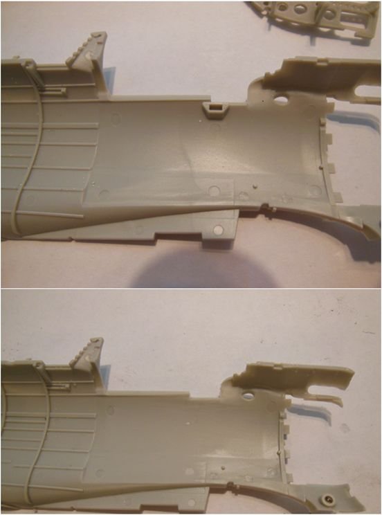
Here we go... For me, the first cut on an expensive kit is the hardest. There was obvious interference between the fuselage and the Aires cockpit; the first thing that had to go was the molded in mount for the throttle quadrant. The fit, after removal, is still too tight...
-
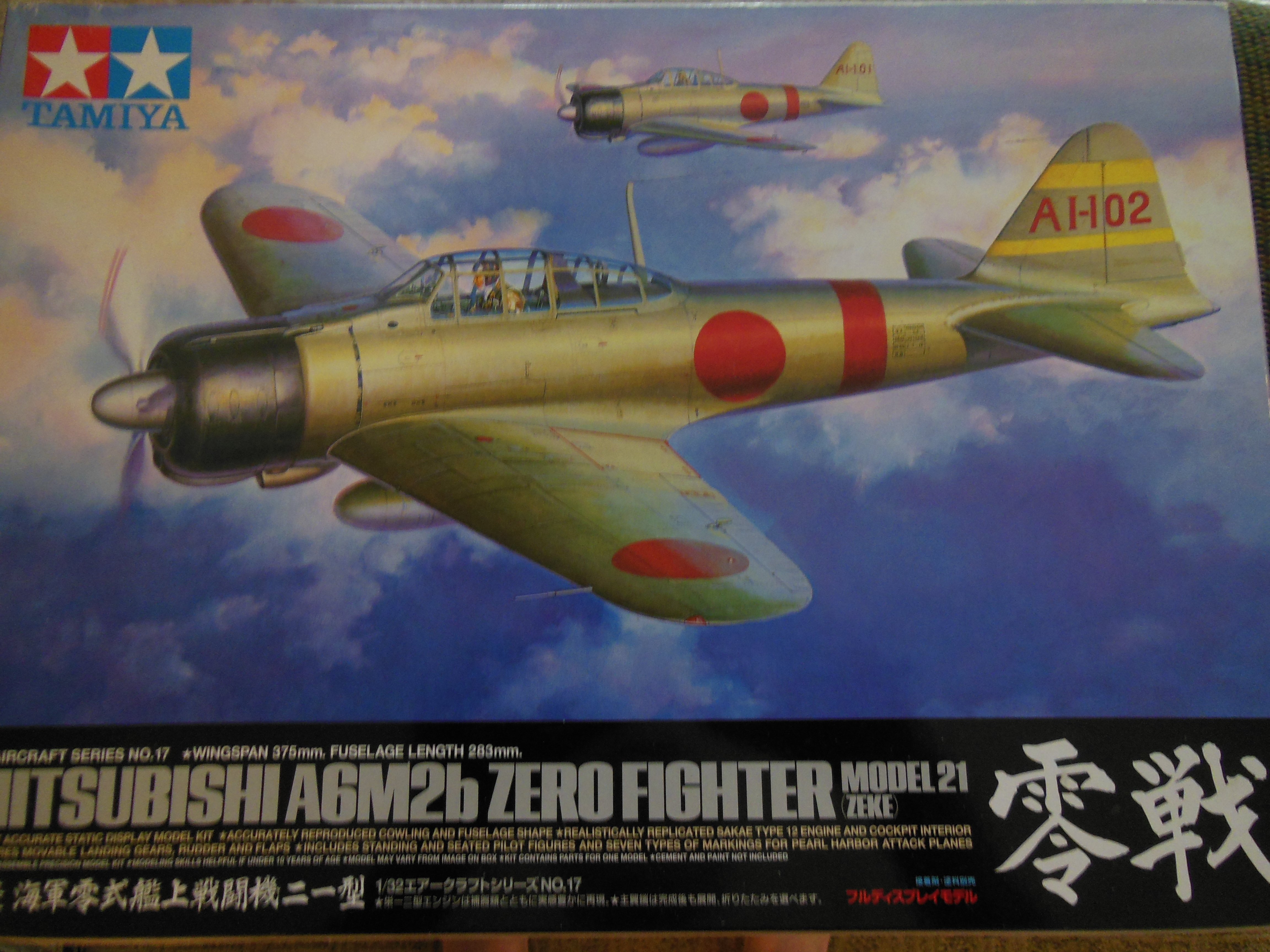
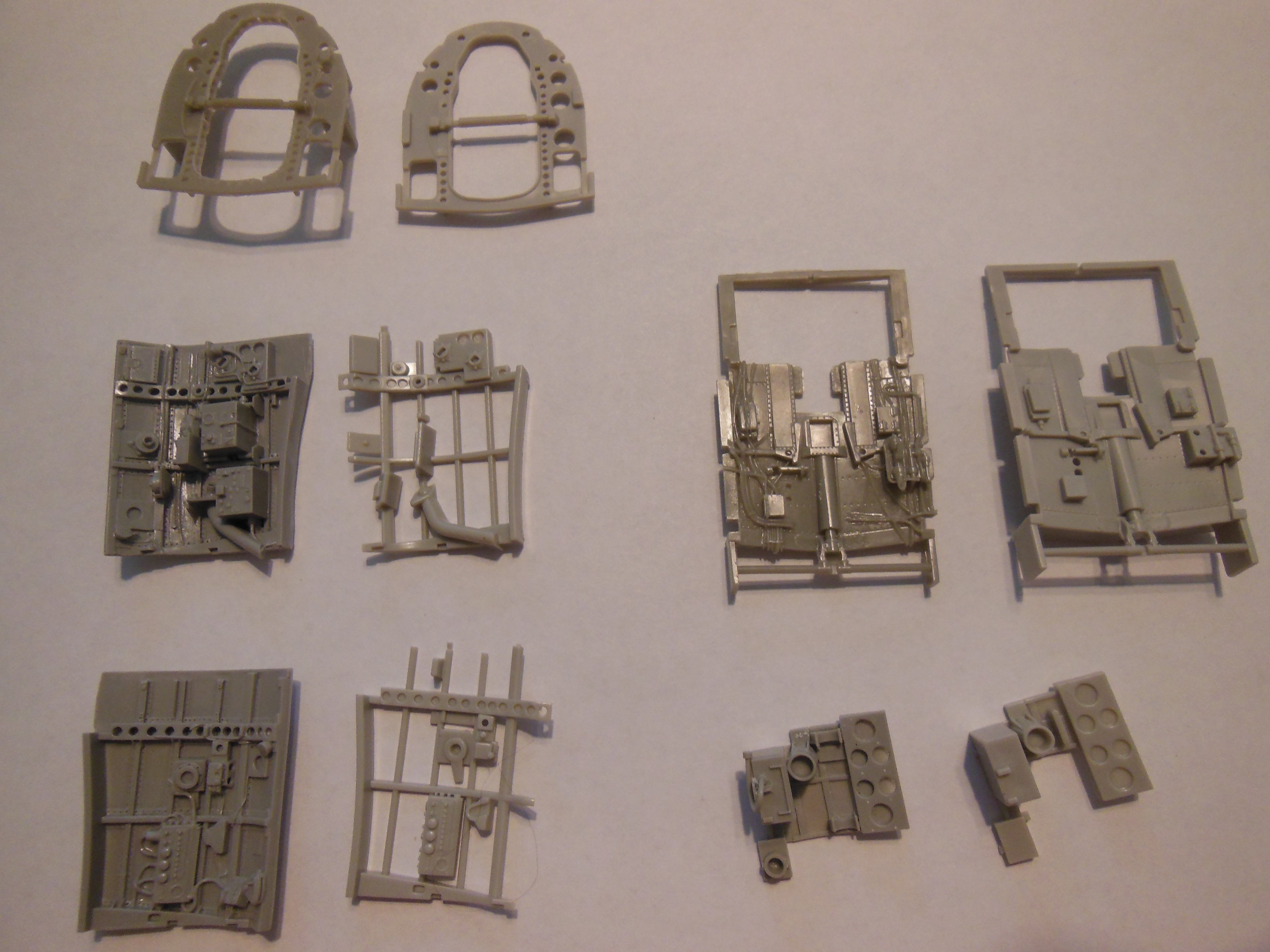
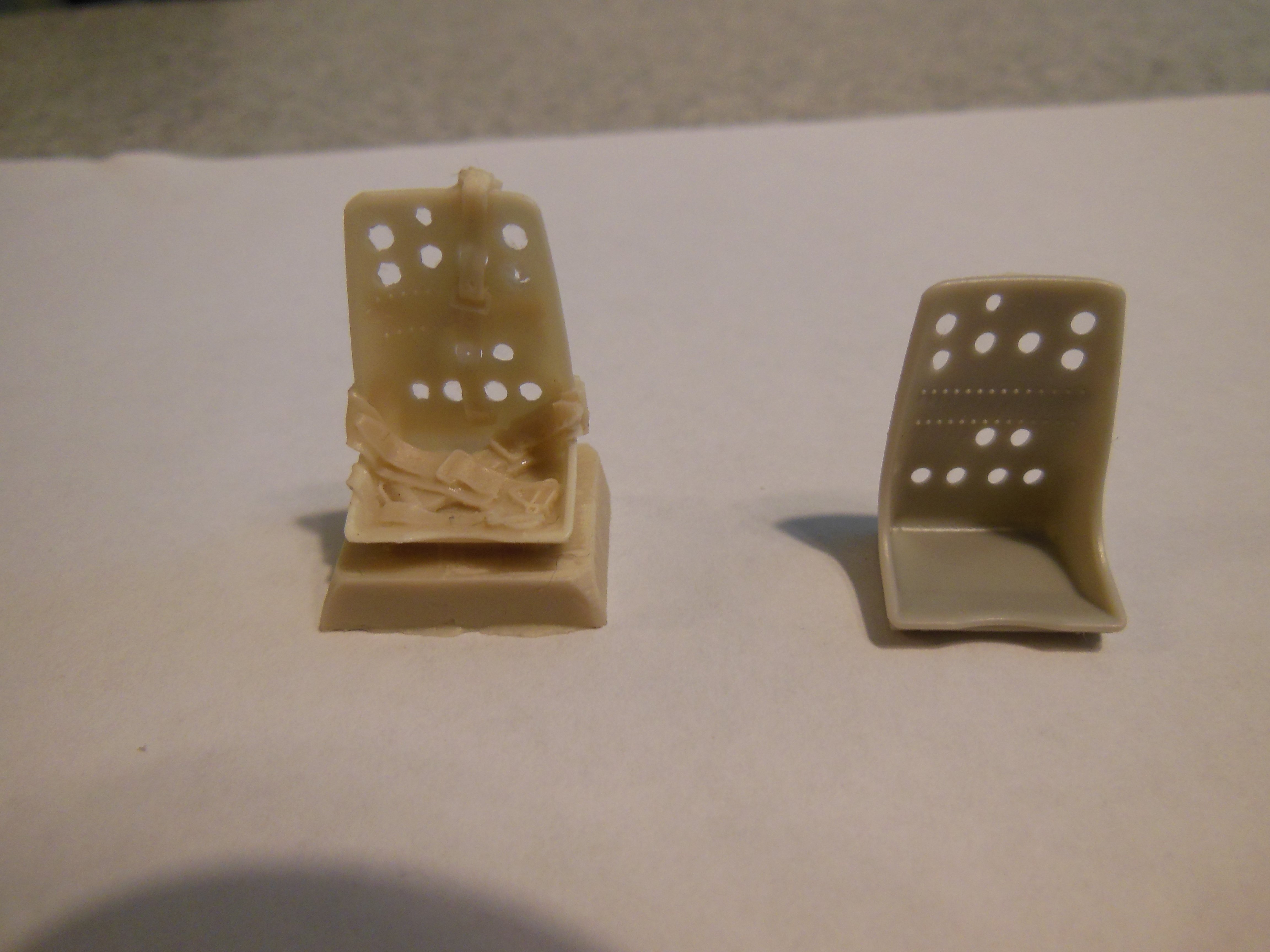
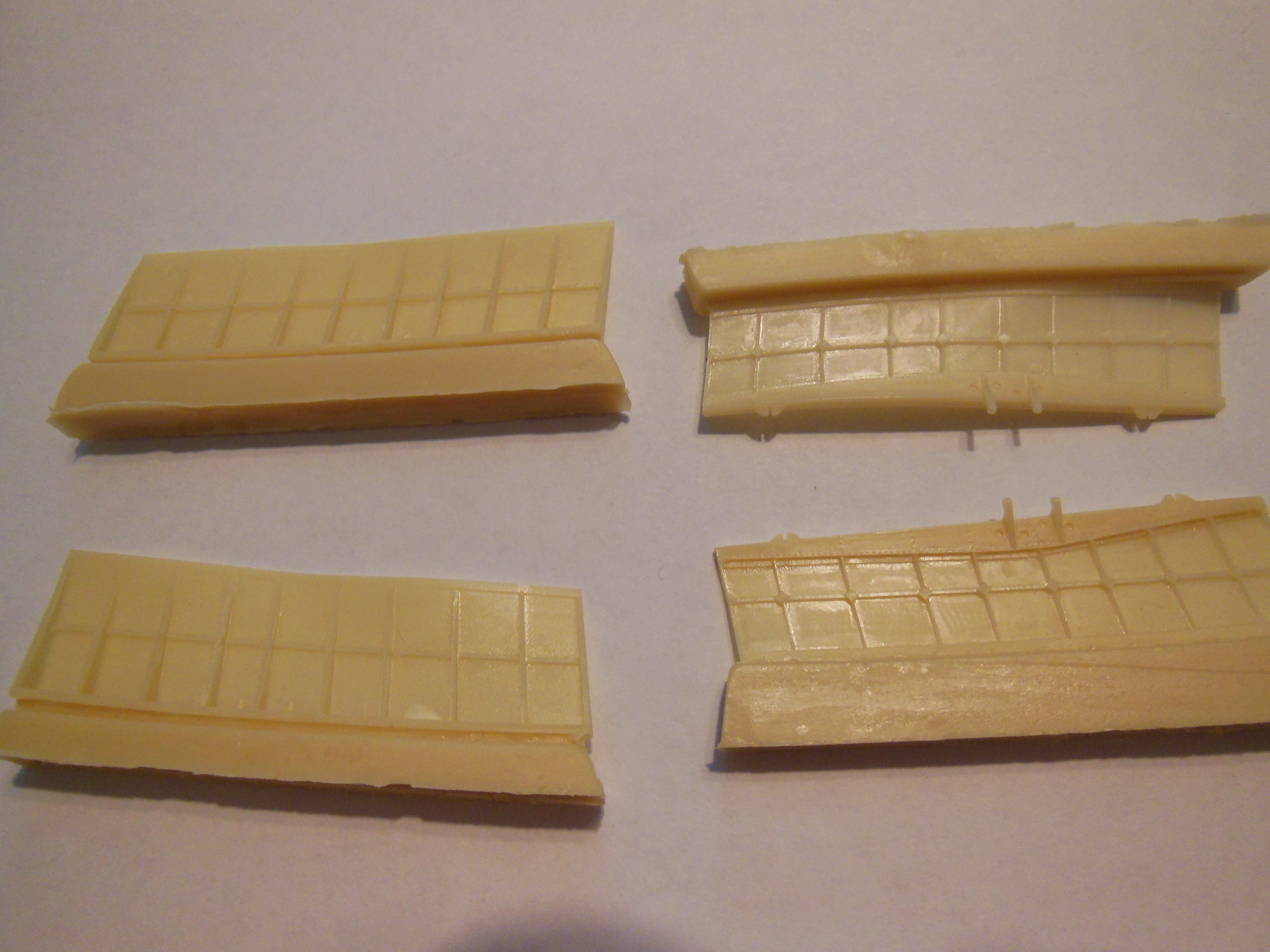
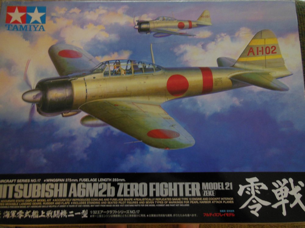
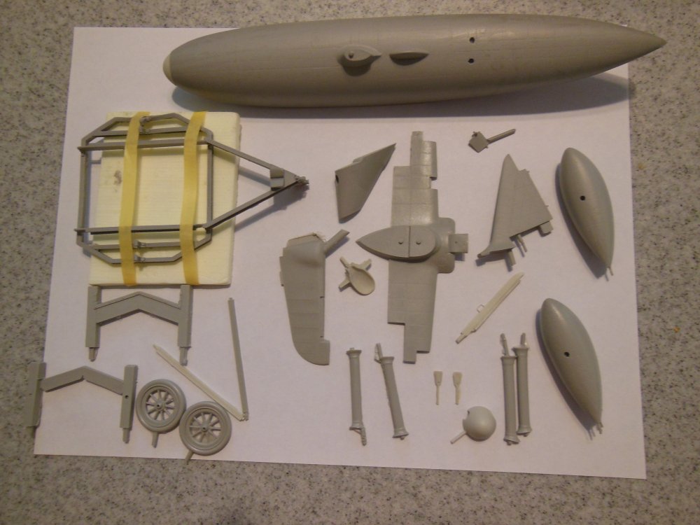
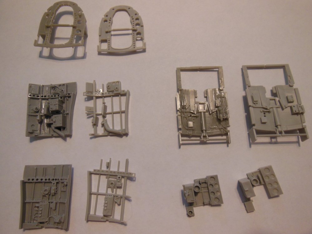
My first "official" WIP thread here. Be forewarned - my build rate makes glaciers appear speedy! The base kit is Tamiya's A6M2 Zero. A beauty of a kit in itself, but I already have the A6M5 - and there's just something about floatplanes... I'll be using the Rufe Conversion set from Model Design Construction. The set includes a replacement rudder/ tailfin, solid resin floats and pylon in addition to various fuselage mods to replace the arrestor hook. A short spinner is also included. The casting on these parts is remarkable! I also bought the Aires A6M2 cockpit. Lots of detail; it remains to be seen how well it will fit in the Tamiya fuselage. Here is a shot of the main pieces from the Aires set, side by side with the kit parts (Aires parts are on the left). I'm undecided on the seat at this point. I can go with the Tamiya part, or use the seat from a CMK A6M5 set with molded in harness. The CMK set also included some very delicately molded flaps; I'll have to see if they'll fit on the A6M2. The only other thing I could want for this kit is a set of REXx exhausts, but I can't find any in stock.


-
I think that leaving the PE on the fret while you thread material is the single best tip for working with harnesses!
-
A little light on armor this year, which really surprised me.
-
Immaculate, as usual!
-
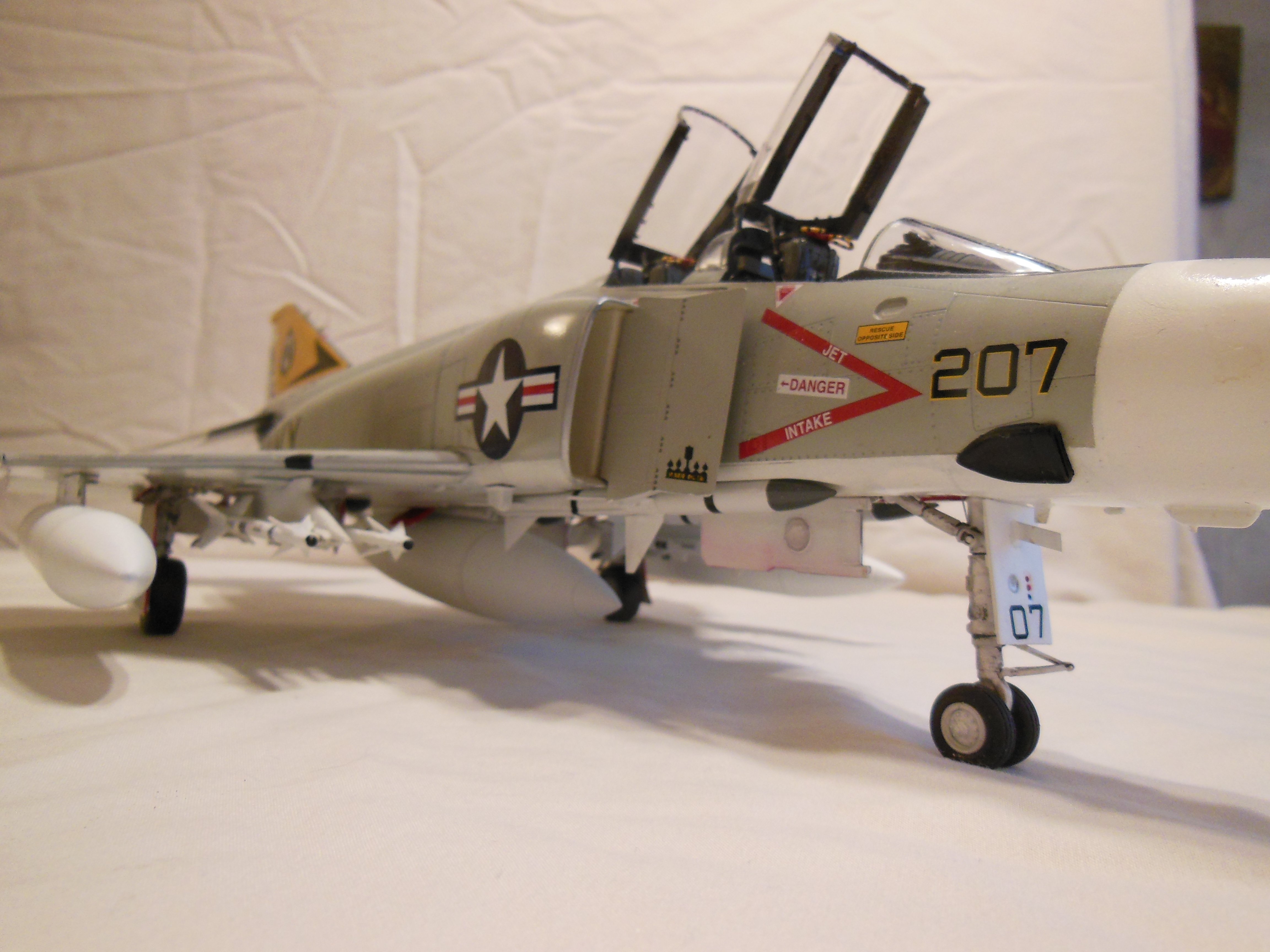
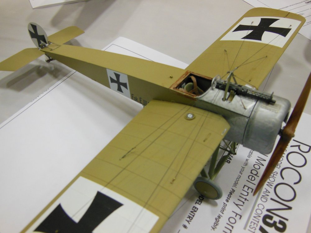
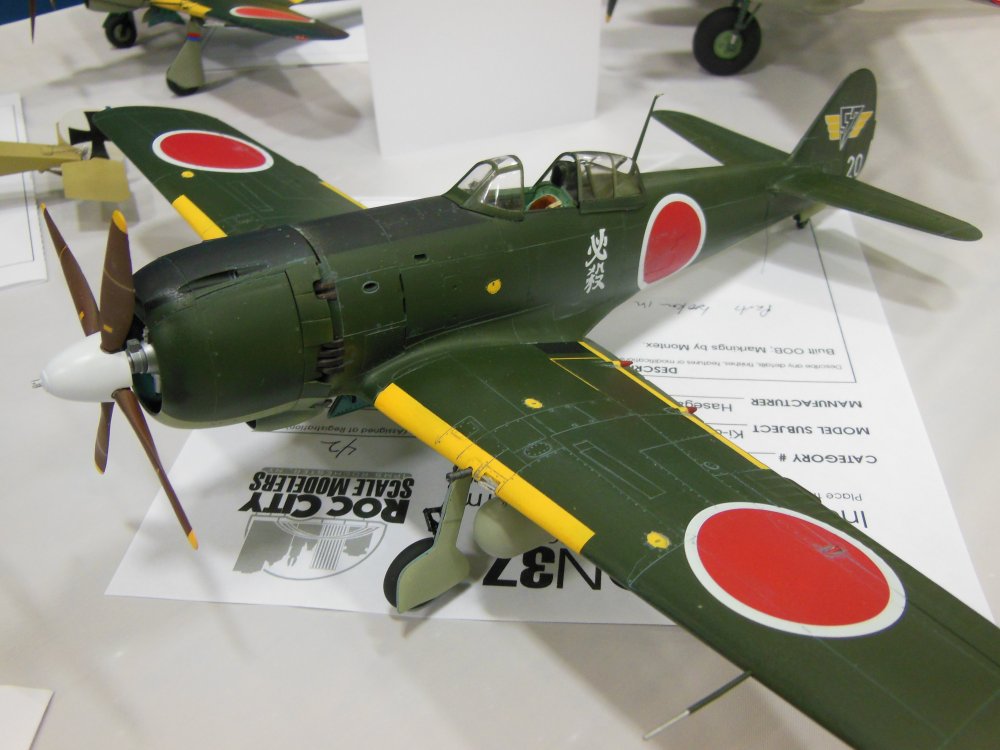
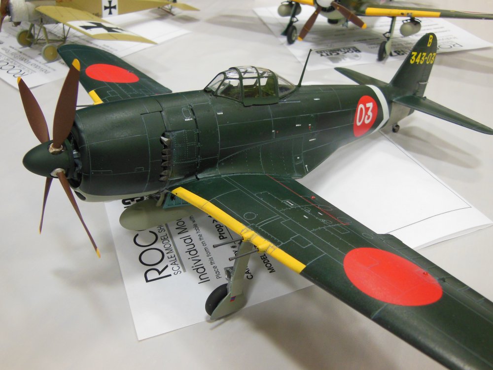
My local club held their show and contest yesterday. Some very impressive builds; only eight planes of large scale showed up, and six of them were mine. I took home three firsts and a second! 1/32 WNW Fokker E.III (Late) First place in the biplane and rigged category. 1/32 Hasegawa Ki-84. First place in large scale props. 1/32 Tamiya F4J. First place in large scale jets. 1/32 Hasegawa N1K2-J. Second place in large scale props. I have plenty of pics of other entries if anyone is interested!

-
Hasegawa F4B-4 UPDATE: 9/22/18: UNDERWAY
Bill_S replied to Peterpools's topic in LSM 1/35 and Larger Work In Progress
That engine looks superb, Peter. I'm looking forward to seeing your build! -
Holding out for a Ploesti raider...
-
OK, is this a mistake or is someone just being a wiseguy.
Bill_S replied to Clunkmeister's topic in General Discussion
I'm sure someone, somewhere is brushing up on their impersonations...
-
George/George/Rex Triple build
Bill_S replied to Bill_S's topic in LSM 1/35 and Larger Work In Progress
Peter, that is solder. What is CCA? -
Nicely done. I can't wait to see some color on it!
- 96 replies
-
- 1
-

-
- 1/32
- special hobby
- (and 1 more)
-
George/George/Rex Triple build
Bill_S replied to Bill_S's topic in LSM 1/35 and Larger Work In Progress
Thanks for the kind comments, guys! A lot of new ground for me here. Scratchbuilders supplied a drawing for a beaching dolly for the Rex; once the lower wing is attached to the fuselage, the thing won't sit anywhere. I cut up a bunch of Evergreen C-Channel, I-beam and strips... On to the wheels. The webs were made from 0.060" (1.5mm) sheet. A hole pattern put in, then roughly cut out. These were then put into my drill press and turned to the proper diameter. I used a similar process for the wheels. They were turned from PVC pipe. I was pretty pleased with the result. -
OK, is this a mistake or is someone just being a wiseguy.
Bill_S replied to Clunkmeister's topic in General Discussion
Very strange... I ordered from them three weeks ago, and it hasn't shipped yet! -
Happy birthday, Maru!
-
George/George/Rex Triple build
Bill_S replied to Bill_S's topic in LSM 1/35 and Larger Work In Progress
Engine time. I sprayed all the cylinder banks with Model Master Aluminum Metalizer. The Hasegawa engine is in the middle. Crossover tubes are from the Brengun sets. Large scale engines don't look complete to me without wiring. Tedious, but worth it to me. The Hasegawa ignition ring. And the Revell version... Wiring in process on the Rex engine. None of it will be visible unless the prop/cowling is removed. The Revell George... And the Hasegawa. I removed material at the back of the intakes and replaced it with a fine mesh screen. The Rex cowling has no intakes. The resin part supplied has a very rounded lip at the intake. All my reference photos show a nearly knife edge at the intake. Some careful sanding later, and I had this. No prop was supplied with the Rex conversion; I put together a simple fixture to set the blades at the recommended 15 degree angle. -
George/George/Rex Triple build
Bill_S replied to Bill_S's topic in LSM 1/35 and Larger Work In Progress
The surface detail on the Revell kit is very subtle, but raised. It had to go. Everything sanded, here is the wing for the Rex rescribed. I used Tamiya white primer so I could see where I had scribed. The main float from the Scratchbuilders conversion is a two piece affair. I epoxied some lead shot inside to prevent a tail sitter. The float on the Rex is big. Compare to the size of the float for the Rufe. The fit between the float halves wasn't the greatest. I used JB Weld to join them. Prior to doing so, I attached the float to the wing. The brass rod goes all the way through the wing. Holding the forward struts in place while the epoxy cured was a challenge. The design on the kits is such that the fuselage halves are glued together first; the cockpit assembly is then inserted through the bottom prior to attaching the wing. The tail on the Rex has a wider chord than its land based counterpart. I cut the extension from sheet styrene and glued it in place. Lots of putty and sanding later, I had this: The opening for the tail wheel had to be filled. The conversion also included a plug the fit on the tail of the fuselage. The Rex had no turnover pylon behind the pilot. This was removed and filled with sheet stock and putty. Prior to joining the fuselage halves on the Revell George, I had to build up the tail wheel. Here I've cemented the two halve together, then sawed and drilled for a brass rod. The tail wheel: I drilled for the rod, then removed the wheel. Then slapped it all together. I turned a new wheel in the drill press... The fusleage halves on the Hasegawa kit got cemented too. -
George/George/Rex Triple build
Bill_S replied to Bill_S's topic in LSM 1/35 and Larger Work In Progress
Thanks for the warm welcome, Rob! This project was started about three years ago. I pulled the Hasegawa kit forward; it will go to my local club's contest this weekend. Once that's over I can dive back in on the other two. I'll post most WIP photos soon, too! -
George/George/Rex Triple build
Bill_S replied to Bill_S's topic in LSM 1/35 and Larger Work In Progress
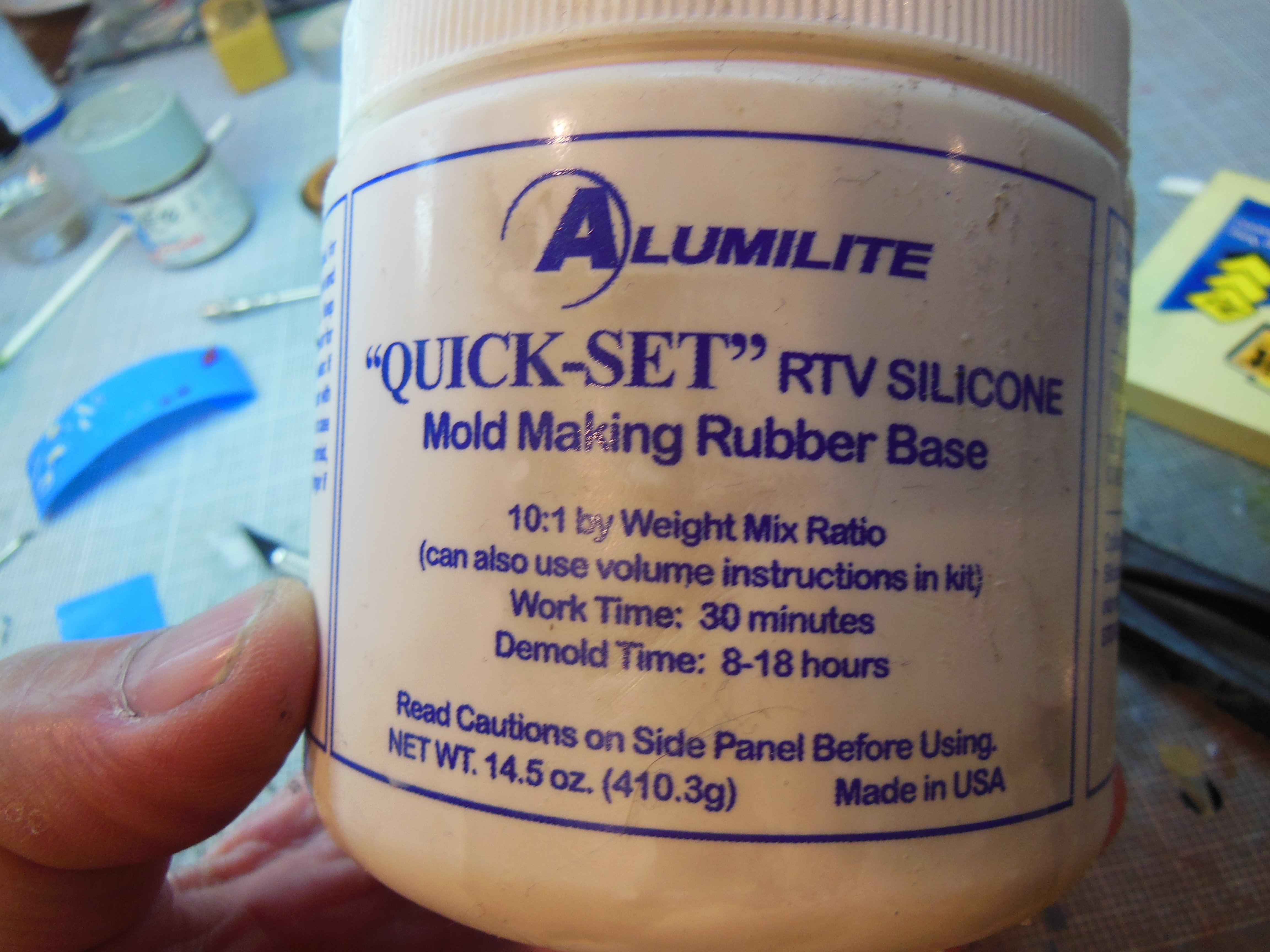
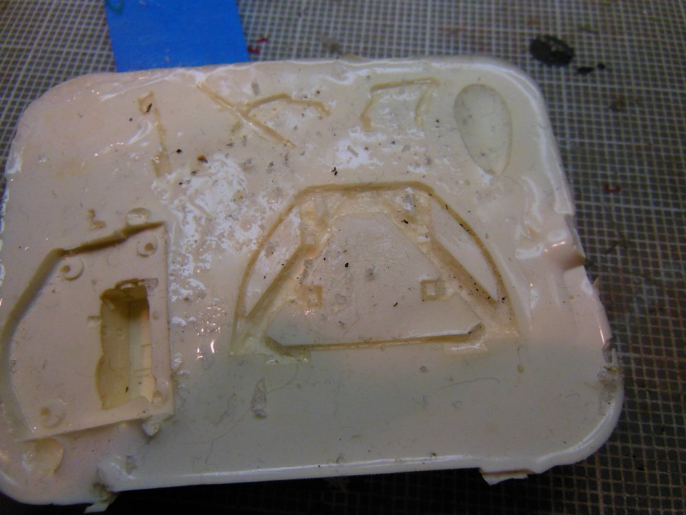
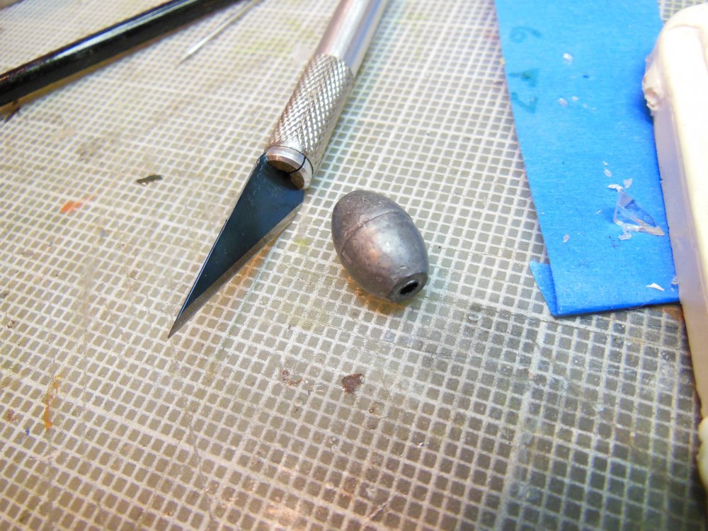
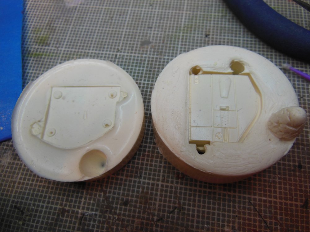
A lot depends on the geometry of the part you want to cast. For the rear bulkhead, there was really only one side with detail, and the part itself didn't have much thickness to it. I used an open mold for that one. The mold itself is pretty ratty these days, but you can see where I "floated" the original part in the rubber before it set. Once the rubber set, I removed the part. I then poured the resin into the mold. This leaves excess material on the back side which can be removed by sanding. I did the seat supports as well as the teardrop for the cannon and the radio. Here is the rubber I used. The resin was Smooth-Cast 300 white by Smooth-On. Parts like the gear bay inserts were a little more involved; it required a two piece mold (and a left and right). First, I glued lengths of sprue to unobjectionable areas of the part; at least two are required. They need to be long enough that they protrude from the rubber when the second half of the mold is poured. The openings left by the sprue are used to pour resin in; the other is for air to escape. Rubber is poured into a suitable container and the part is floated on the rubber. As I recall, I used forceps to hold the sprue and prevent the part from tipping or sinking into the liquid rubber. In addition, you need some kind of locating mechanism to ensure that the two mold halves align properly. I used some fishing sinkers for this. Once the bottom half has set, the sinkers were removed. A little petroleum jelly was brushed on the top surface of the bottom mold to prevent the two mold halves from sticking together. The part master was left in the mold, and more rubber poured on top. Once cured, the mold can be separated and the master removed. I did much the same for cockpit sidewalls, but the parts didn't turn out as well as I would have liked. I ended up going a different route for them. If I was to cast this part again, I would attach sprue to the back side of the part instead of using the "pour stub" approach. I hope I've answered your question adequately!

-
Jerry Rutman P-51B build
Bill_S replied to Clunkmeister's topic in LSM 1/35 and Larger Work In Progress
Those things will drive your eyes crazy! -
George/George/Rex Triple build
Bill_S replied to Bill_S's topic in LSM 1/35 and Larger Work In Progress
Cockpits coming along... Hasegawa control column on the left, Revell on the right. Many of the smaller parts on the Revell kits had soft detail. I scratch built replacements. No pictures of the finished product, but here is one in process. Rex cockpit nearly complete; it's awaiting an instrument panel at this point... Instrument panels for the N1K2 (left) and Rex (right). And the N1K1-J... It looks much better to the naked eye... -
George/George/Rex Triple build
Bill_S replied to Bill_S's topic in LSM 1/35 and Larger Work In Progress
Initial cockpit work on the Revell. Brengun PE with styrene added. Scratch built seat from sheet copper. I CA'd solder along the sharp edges. Finished product. Some consoles for the starboard side of the cockpit. Beginnings of the throttle quadrant. On the mid-wing Georges, it was mounted to the console. On the later low-wing George, the throttle was mounted to the sidewall. Complete... Rudder pedals were scratched also. The top is the Hasegawa stock part.