Administrators JayDee Posted March 18, 2019 Administrators Posted March 18, 2019 1:32 Supermarine Attacker F1/FB2 Iconicair Available from Iconicair for £115 plus postage The Supermarine Attacker is a British single-seat naval jet fighter built by Supermarine for the Royal Navy's Fleet Air Arm (FAA). The type has the distinction of being the first jet fighter to enter operational service with the FAA. Like most other first-generation jet fighters, it had a short service life due to the rapid development of increasingly advanced aircraft during the 1950s and 1960s. The Attacker developed from a Royal Air Force (RAF) fighter jet project, under Air Ministry Specification E.10 of 1944 (the E for experimental). The design of the Attacker used the laminar flow straight-wings of the Supermarine Spiteful, a piston-engine fighter intended to replace the Supermarine Spitfire, and what became the Attacker was originally referred to as the "Jet Spiteful". The project was intended to provide an interim fighter for the RAF while another aircraft, the Gloster E.1/44 also using the Nene engine, was developed. An order for three prototypes was placed on 30 August 1944, the second and third of which were to be navalised. An order for a further 24 pre-production aircraft, six for the RAF and the remaining 18 for the Fleet Air Arm was placed on 7 July 1945. The Attacker suffered from deficiencies which led to it quickly being superseded; one being that the aircraft retained the Spiteful's tail-wheel undercarriage (due to the extent of the re-tooling that would have been required to alter the Spiteful's wing), rather than a nose-wheel undercarriage, thus making the Attacker more difficult to land on aircraft carriers. Also the new wing was apparently aerodynamically inferior to the original Spitfire elliptic one, with lower critical Mach number, leading to someone quipping that "they rather should have left the Spitfire wing on the thing". The Attacker had a brief career with the Fleet Air Arm, not seeing any action during its time with the FAA and being taken out of first-line service in 1954. It remained in service with the Royal Naval Volunteer Reserve (RNVR) for a little while longer, being taken out of service in early 1957. The Attacker was replaced in the front-line squadrons by the later and more capable Hawker Sea Hawk and de Havilland Sea Venom. The Royal Pakistan Air Force also purchased a number of de-navalised Attackers in the early 1950s. The UK and Pakistan were the only countries to operate the type, of which a total of 185 were built. The kit Iconicair’s 1:32 Supermarine Attacker was launched during the latter part of 2018, and we are grateful to them to be able to show this kit here on LSM. The kit itself is packaged into a fairly large and robust box with a nice painting of an Attacker about to be launched from HMS Eagle, and with the box edges showing the schemes available for your built model. Of course, this is a resin kit with a number of metal parts, so bear in mind that extra effort will be needed to assemble, over and above a regular injection-moulded styrene kit. Ok, let’s take a closer look. Lifting the lid reveals a swathe of bubble-wrap sheet layers which carefully protect the various zip-lock bags of resin, plus the PE and white metal parts. Removing all of this reveals a single decal sheet and a 14-page instruction manual. Some of these resin parts are quite chunky and heavy, and this is of course reflected in the overall weight of the package. A number of zip-lock bags are used to hold the various parts, with them being laid out in an orderly way within the box, to avoid any possible damage. Some of the bags have casting blocks included which are further bagged, or even bubble-wrapped for those components which are perhaps more prone to being broken. Each of the two canopy sets is individually bagged, and stapled together, along with the wallets for the white metal u/c and PE fret. Our first bag contains the main fuselage halves (sans nose), belly fuel tank and a casting block of smaller components. By far the largest components are the tapering, cylindrical-ish main fuselage halves. External detail on these is very nicely engraved, and depicts the panel lines, fasteners, access panels, louvres, wing root fillet etc. superbly. The details should take a wash very nicely. You’ll note that the wing spars have a location slot into the fuselage. If there is one thing I would perhaps do with this model and that’s to add some subtle flush-riveting with a beading tool, to help create a little extra visual interest. There are no casting blocks with these main parts, and there is also a small number of alignment tabs cast to one half. I would probably remove these as I feel the joint surfaces need drawing over some wet ‘n dry paper to properly even them after the casting blocks/edges were removed by Iconicair. You can always add new alignment methods yourself. A single-piece belly fuel tank is included, and my test fitting shows a small amount of fiddle will be required to get it to seat fully, but nothing too onerous. I’m sure I’ve seen some images of the belly tank with raised riveting around the belly seal but would need to check that further as none is depicted here. The long casting block contains the cockpit floor, intake parts, seat parts, instrument panel chassis etc. Again, everything is cleanly cast and there won’t be too much cleaning up needed when removed from the block. Our second bag is smaller but still nicely packed out with resin. Here you will find the cockpit/nose section, which is supplied as halves. These include the intake edge to them also. External detail is commensurate with that of the fuselage we’ve just seen, and some minimal clean-up will be required before use. Internally, these contain the various cockpit structures into which the side consoles etc. will fit. You’ll of course need no nose-weight here as the Attacker has a tailwheel configuration. I did a quick test fit of the nose to the fuselage and found things were reasonable. I will need to pack out the fuselage a little though as it isn’t as wide as the edge of the nose section mating area. Other parts in this bag contain more intake parts, the ejection seat, and two separately wrapped casting blocks with multiple components. There are yet more parts for the ejection seat, seat mounting rail, several cockpit detail parts including the three-piece instrument panel fascia, map case, avionics etc. Some light flash will need to be removed, but this is nothing unusual for a kit of this type. Our third beg of resin contains a yet more casting blocks that contain many parts pertaining to the undercarriage bay and gear door areas. Two of the initial blocks are more or less mirror images of each other, with those chunky wing spars and other wheel well liners, complete with wall details. The last block in this picture holds some of the landing gear doors. Whilst there is internal detail, externally, they are blank. Thankfully, some brass strengthening has been cast within the wing fold hinges too. Here, we have more gear bay door parts, and also the main wheels and hubs. Tyre detail is nice, but care will need to be taken when removing from the casting block. They also aren’t weighted. Wheel hub detail is delicate, but only on one side. The reverse of these is totally blank. One singe block is protected by bubble-wrap, containing the cannon barrel fairings, pitot and several small parts from the main gear bays. Bag no.4 is chock-full of flying surfaces. This is pretty much where you’ll find all the wing parts. The Attacker can have its wings posed in a folded position, and as a result, each wing is cast to that effect. Each of the main, inboard wing panels is cast as a complete upper unit with partial lower panels too. The panels that are cast separately are done so in this way so the wing spars and gear bay liners can be fitted first. This prevents a serious undercut needing to be made in the moulds. Landing flaps and aileron parts are also cast in situ, so you won’t be able to pose these without serious surgery and/or scratch-building work. Surface details are excellent, but again for me, would be enhanced with some nice flush rivet additions. Of course the end of these wing sections is cast hollow to accommodate the wing fold hinge. Note that there is no actual detail in this area so you will need to do some work if you want to depict folded wings. The same applies to the wingtip folded parts. Minimal clean-up will be required in all respects, but I also note that the wingtip lights are moulded in situ and not supplied as clear resin. I think I’ll fix that anomaly when I come to build this. Onto the last bag of grey resin now. As with the wings, the elevators and rudder are cast as one piece with their corresponding tail surfaces. To pose these separately will require a little extra work. Surface detail is basic, so again, some nice, subtle riveting wouldn’t go amiss. The rearmost fuselage section for the tail pipe/exhaust area is cast as a single piece and fits quite nicely to the main fuselage parts. Very nice louvre details here, but again, the entire hollow fuselage will be seen through this and you should ideally find a solution to this problem. A casting block contains all parts for the rear tailwheel bay and tail hook. Here we have a small posse of bags which hold the last parts for this kit. Iconicair have done a very nice job of casting the clear resin parts. Two sets are included, with the minimally framed F.1 and the heftier-framed FB.2. Of course, you will need to remove the casting blocks, but the clarity on my sample is very good and shouldn’t need any further work. No masks are supplied with this model, so it’s the traditional hand-made mask technique that you’ll need to employ. Main gear struts and actuators are supplied as white metal parts. Whilst some edges are nicely defined, some detail is now and you’ll need to do quite a lot of cleaning up before use, especially on the seams. Lastly, a single PE fret is included that contains the pilot seatbelts and the instrument coaming. Production is very nice, if not perhaps a little thick. Some annealing will be needed to get it to drape realistically. Instructions The 14-page instructions manual is printed on 7 sheets of glossy and heavy A4 paper, stapled at one corner. The front shows a photo of a completed model, and the build is broken down into 23 constructional sequences. Stage 24 was missing, and the final assembly sequences weren’t included, but an email to Graham, and the files were quickly sent to me. Illustration is by means of clear, fine line drawings with some minimal annotation. Things look pretty easy to assemble, but like with any full resin kit, you’ll need to think a few stages ahead and have your wits about you. The last few pages are taken over with colour-printed profiles for the two schemes supplied in this release. Decals A single sheet of decals is provided, printed by Fantasy Printshop. I know their decals to be of extremely high quality, and these have excellent colour density, minimal carrier film and are in perfect register. As well as the decals for the TWO schemes, a three-part instrument panel decal is supplied, as well as a small number of stencils. By their very nature, the FAA schemes for this are quite simple and almost identical too. The schemes included are for: Supermarine Attacker FB.2, WP286/J-101, No.800 Naval Air Squadron, FAA, HMS Eagle Supermarine Attacker F.1, WA492/J-104, No.800 Naval Air Squadron, FAA, HMS Eagle, 1952 Conclusion This is a very nice kit of an oft-forgotten type, which is perhaps more deserving of its place in aviation history, especially when you consider the Spiteful link, and the direct lineage to the Spitfire family. Iconicair has produced a model with a fairly simple breakdown and some thoughtful engineering, along with some nicely rendered surface detail. There are some areas which I think would benefit from extra detail, such as the gear bays, wing-fold area, and the void behind the pilot seat. A lack of exhaust tunnel with a fan face is also something you’ll have to fathom yourself. Perhaps, for me, something which does look a little strange in comparison to period and contemporary photos is the beautifully clear resin canopy. In this kit, it seems quite bulbous and tall. I could be wrong. Whilst I do have some criticism of this kit, in all, it should look superb when complete and will certainly be the only incarnation of this currently available in 1:32. Watch out for this soon as I build it for Military Illustrated Modeller magazine. Now….if there were some rockets for this too! My sincere thanks to Iconicair for the sample reviewed here. To purchase directly, click the link at the top of this article. 4
Ryan Posted March 18, 2019 Posted March 18, 2019 Nice product, how does the clear resin hold up to yellowing? Ryan 3
Administrators JayDee Posted March 18, 2019 Author Administrators Posted March 18, 2019 1 hour ago, Ryan said: Nice product, how does the clear resin hold up to yellowing? Ryan As the kit has only been in my possession a short while, I can't really say. 1
Ryan Posted March 18, 2019 Posted March 18, 2019 Yeah prob should have rephrased my question "in general" how does clear resin hold up. 3
Administrators JayDee Posted March 18, 2019 Author Administrators Posted March 18, 2019 The clear resin is good, well cast, nice definition and with very good clarity. 3
Administrators Clunkmeister Posted March 19, 2019 Administrators Posted March 19, 2019 Oooooh, James, if I didn’t have a big Lanc to finish, and then write a review and build a 1/32 Dak, I’d be on my knees groveling to build this... this kit has serious coolness baked into it! 3
Bomber_County Posted March 24, 2019 Posted March 24, 2019 Ernie and it’s resin ........double win win 1
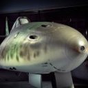
Wingco57 Posted March 25, 2019 Posted March 25, 2019 Very nice review James. Graham told me that there are no surviving drawing of the Attacker and he measured the last remaining one at Yeovilton. Also there have been some reports on the net that the intakes are wider than the rear fuselage that fits onto them. I read in the instructions that it was because the intake rims are more bulbous. Will have to check first. Cees
Administrators JayDee Posted March 25, 2019 Author Administrators Posted March 25, 2019 Even if you left the intakes protruding slightly, there is still a gap that needs to be filled. It's not a big job though and if you set about to build a resin kit, then you should have the ability to fix it. 1

Recommended Posts
Create an account or sign in to comment
You need to be a member in order to leave a comment
Create an account
Sign up for a new account in our community. It's easy!
Register a new accountSign in
Already have an account? Sign in here.
Sign In Now