CrankyCrafstman
-
Posts
1,358 -
Joined
-
Last visited
Content Type
Profiles
Forums
Events
Gallery
Everything posted by CrankyCrafstman
-

1/24 scale DHC-2 Beaver build
CrankyCrafstman replied to CrankyCrafstman's topic in Modelling Discussion
WOW Jeff! Great shots of the floats, thanks greatly my friend. Ron G -
1/24 scale DHC-2 Beaver build
CrankyCrafstman replied to CrankyCrafstman's topic in Modelling Discussion
Thanks Jeff -
1/24 scale DHC-2 Beaver build
CrankyCrafstman replied to CrankyCrafstman's topic in Modelling Discussion
I think there is one left on Ebay, it's the white plastic one, it's a pacific airways one same manufacturer, but it is the same one just different color plastic. I think the bid was at $60.00 plus $19.05 shipping last I checked, but better hurry these are as scarse as hens teeth. Ron G -
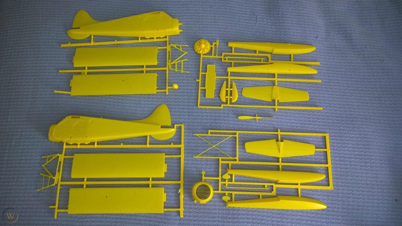
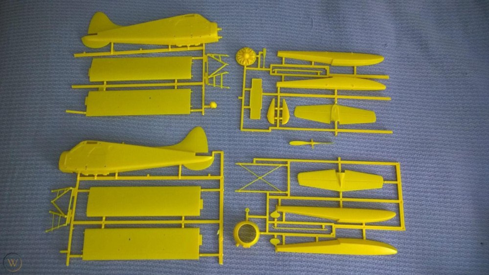
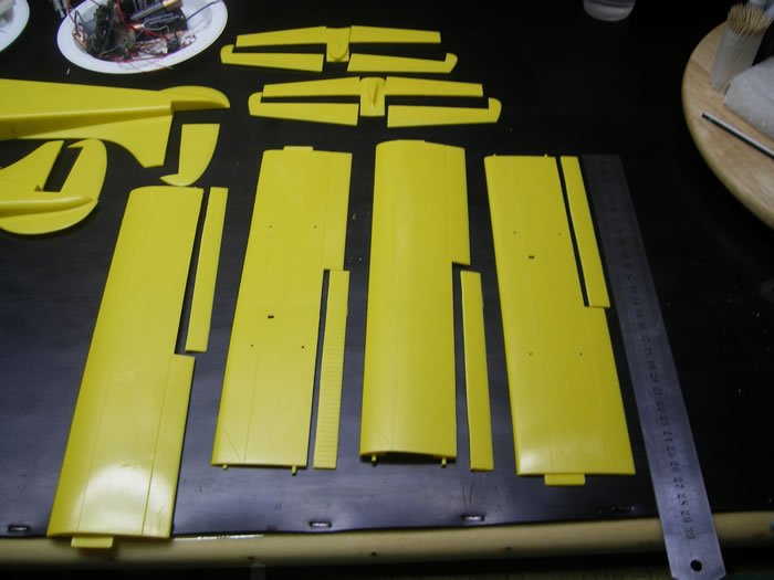
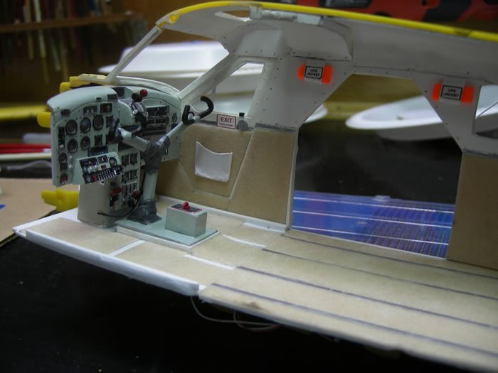
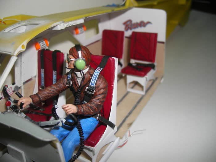
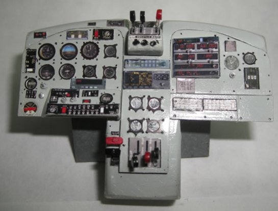
Hey all I just got this from an Ebay auction...yahoo I won. Anyway I am going to be doing a build on this. It is an old (1979ish) snap together kit from Cedar Creek. It is a very simple kit, no windows or interior. It has decals for the windows. I'll be cutting out the windows and making windows from clear plastic sheet. I'll also be doing a complete as possible interior. I'm in the process of accumulating as much info on this plane as I can. If any of you have photos, documents, etc. please share. this is what comes in the kit. Not much. this is what I plan on doing, this was a photo takin from another build. Have to cut out all the flaps, ailerons, elevators and rudder. this is a photo from another build showing what has to be scratch built for the interior. same build showing custom pilot figure and rest of interior. Alot of work! have to make this from scratch. I'm going to be using Airscales 1/24 gauage faces and instrument bezels. Ordered some balls, 1/32" dia. For control knobs also some levers, door handles and PE seats, there for automotive models, but will work fine for what I want. It's going to be a big under taking. All the rivets and line detail is raised, and will need to be sanded off and rescrbed and reriveted, thats going to be fun...lol. So wish me luck and all the help you can give. Thanks Ron G
-
Yeah that one was really cool with the working motor and sound, plus all the rest of the diorama. I'm still looking for a good paint scheme. And I need alot of info on this bird especially interior photos and dimensions. Ron G
-
Possibly my next project in 1/24 scale. it's a 1/24 de Havilland DHC-2 Beaver. Very simple snap together kit. I plan on super detailing this with complete scrach built interior. I have to cut out the window openings and add clear plastic. It's definitely going to be a lot of work. So wish me luck, I'm going to need it! Ron G

-
Thanks Ernie And it's Ron not Don
-
Hey Captain You are welcome. A word of advice the spark plugs are very tiny and intricate, even for 1/24 scale. I'm not trying to say they are bad just be very careful they are difficult to assemble and easilylost to the dreaded carpet monster. You may need extras. I bought three sets of the spark plugs, since I have two Hellcats one set for extras. The plug wires are tricky to attach to the spark plugs so be forewarned. Don't rush take your time and you will have a great kit. Have you looked into the Master Model's brass barrels for the Hellcat, also the brass undercarriage. I recommend both they will make your model better. Ron G
-
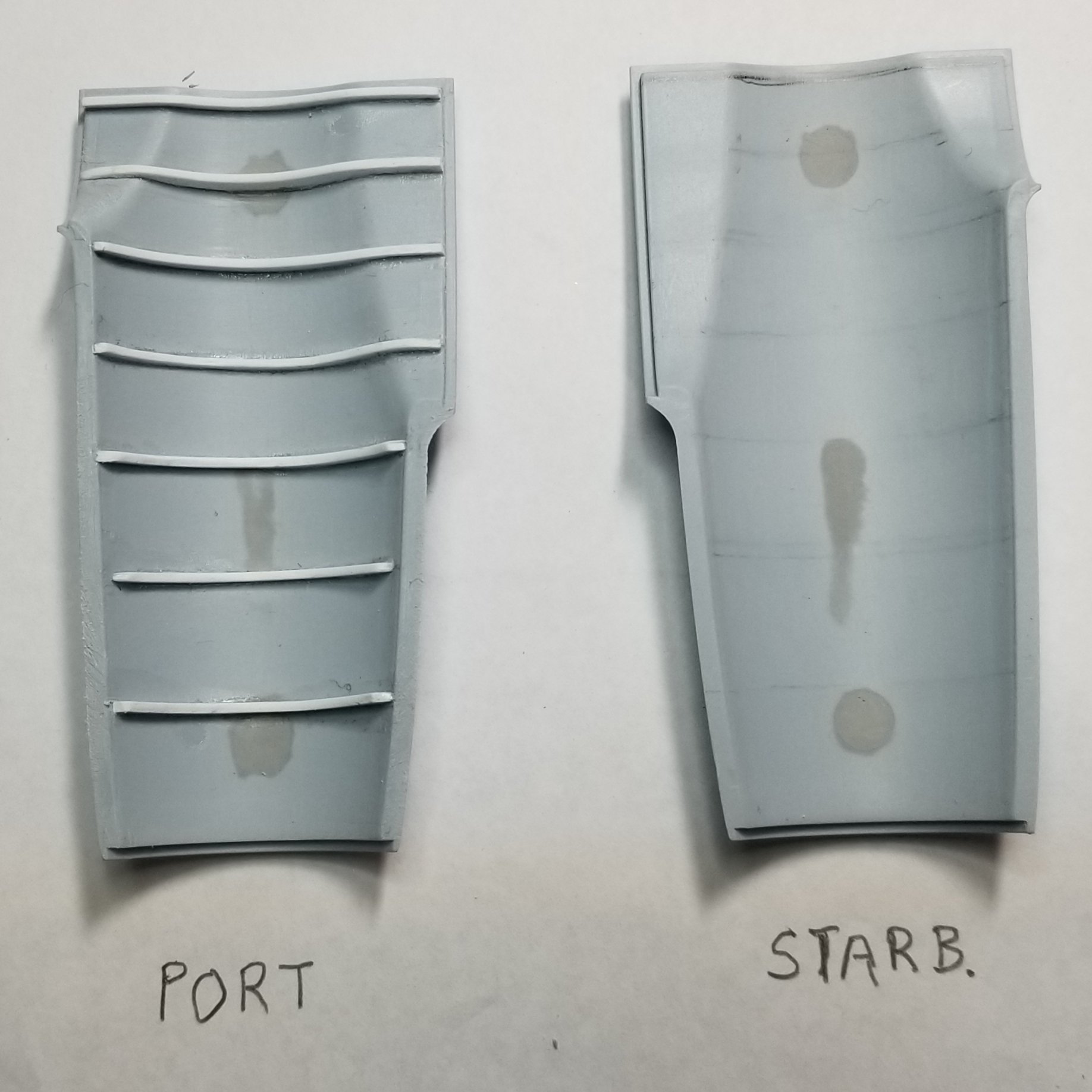
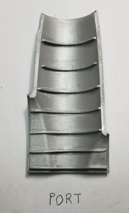
Just a small update. Thanks to Anthony in NZ for supplied pictures. this is a picture of the top engine cover on the Mosquito. these are the kit parts. The Starboard one is the why it comes in the kit. The Port one is after I modified it to look like the one in the photo. this is it after painting it with Vallejo metal colors dull aluminum. It still needs some clean up and weathering, but I ran out of umff, so more later when I have recharged the old body. Ron G


-
Hey Hubert Your going to love that new Infinity. When I got mine, just recently, with the 0.2mm needle installed I mixed up some Vallejo model air and could paint 1/2 mm lines like I was drawing with a pencil! My Paasche Raptor couldn't even come close. Ron G
-
Hey captain I'm using the ones from ANYZ. He makes a complete kit for the 1/24 Hellcat. Mine will be a US Navy plane probably a late 3 that had the up dated canopy. I believe you can get the Gaspatch guns in, but I would have to pull mine off the shelf and do some investigating, as I'm in the middle of my 1/24 Mosquito. Ron G
-
If you are going to close up the wings, (as in gun covers on) why worry about the guns they won't be seen. Ron G
-
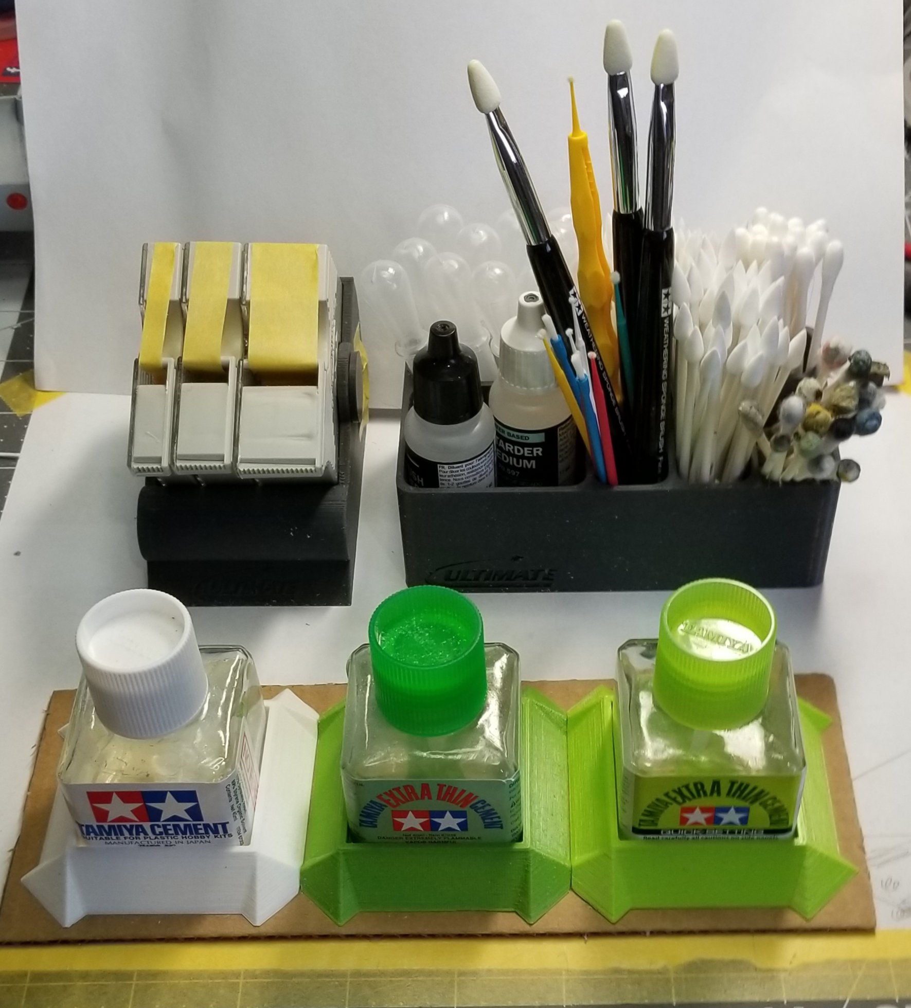
Just got these from Ultimate. Ron G

-
Tamiya Mossie build resumed
CrankyCrafstman replied to JohnB's topic in LSM 1/35 and Larger Work In Progress
Hey John I'll bet you will have it done before I finish my 1/24 Mossie. ...I'll be following along for the ride. Ron G -
Thanks guys
-
Hey guys I almost forgot to let you guys know that Piotr at Master Model's has two new sets for the 1/24 Hellcat. An early set for the F6F-3 Hellcat, barrels with cooling holes unshrouded set# am-24-018 and set# am-24-019 shrouded barrels for the F6F-5. They don't show on his site yet but they should be available in a week or so. So keep a look out and get a set they will make a big difference to the look of your model. Ron G
-
Just got this for my birthday. harder_and_steenbeck_infinity_CR_plus_2in1_by_spraygunner__76194.1523118103.webp What a difference a quality airbrush makes. I sprayed some Vallejo grey/green for a test. I made some 1/2 mm lines like I was drawing with a pencil WOW! I could never do that with my Paasche talon or raptor, and easy to clean. I'm really impressed and now I can't wait to start paint on my 1/24 Mossie build. Ron G
-
F4U-1A finished!
CrankyCrafstman replied to JohnB's topic in LSM 1/32 and Larger Aircraft Ready for Inspection
Thanks John I'll look into that. Ron G -
F4U-1A finished!
CrankyCrafstman replied to JohnB's topic in LSM 1/32 and Larger Aircraft Ready for Inspection
Great build John So I thought I would ask the ranking Corsair guru a few questions. First I have a Tamiya F4U-1A that I would like to do as Boyingtons bird. My question is what color was the rear wheel well area samon or zink chromate? What color was the cockpit? What color were the main wheel wells? Any other info that you can provide would be greatly appreciated. Ron G -
1) In harms way - I like John Wayne, plus it was a cool movie. 2) Midway - great movie 3) Enemy below - good Robert Mitchum movie. 4) Tora, Tora, Tora - great movie 5) Airforce - great movie on the B-17 I have alot more but thats 5 Ron G
-
I have a really great wife, she got me a H&S Infinity plus 0.2mm/0.4mm with both cups, thanks babe Ron G
-
LMAO
-
Thanks guys
-
Hey Ernie do they make mr surfacer 500 in flesh tone? Ron G
-
Glad to see you made it through surgery Carl. Know relax as best you can and get well soon all our best. Ron G