Peterpools Posted May 23, 2024 Posted May 23, 2024 Rob WOW, underway and I'm still amazed at the organization of working through the first assemblies. Clearly, one of the most important technical skills for these types of kits, is the ability to understand the required assembly procedure, organize the parts and then work slowly toward a completed part. Looking mighty good. 1 1
DocRob Posted May 24, 2024 Author Posted May 24, 2024 15 hours ago, belugawhaleman said: What adhesive will be used? CA, epoxy,? Any soldering? Until now, I haven´t used any. I will mainly use my trusty Colle 21 CA and hope to not need epoxy, as I have none. I will test soldering with some cast residues, but have no experience soldering white metal, let´s see.... Cheers Rob 4 1
DocRob Posted May 24, 2024 Author Posted May 24, 2024 10 hours ago, Peterpools said: WOW, underway and I'm still amazed at the organization of working through the first assemblies. Clearly, one of the most important technical skills for these types of kits, is the ability to understand the required assembly procedure, organize the parts and then work slowly toward a completed part. Looking mighty good. Thank you Peter, working with white metal is quite different than working with plastic. The engine casing looks fantastic as it is, with no need for Alclad´s. The holes in the white metal parts are pre cast very precisely, luckily. You have only to drill them out with the appropriate drill bit. There are lot of parts being attached to the engine housing, and all these need to be joined with tiny rivets, bolts or screws and all these holes need to be drilled out. I´m sure, I will miss some, but hope they are in places, where I can reach them later. Cheers Rob 5
BlrwestSiR Posted May 24, 2024 Posted May 24, 2024 The cylinder head looks amazing. The individual fins are an interesting approach but I guess it makes it easier than trying to clean up a mould seam from between each one if it was cast as a single part. 4 1
Bomber_County Posted May 24, 2024 Posted May 24, 2024 Rob, this kit looks amazing and with your skill level it’s going to be stunning. With white metal you will need a variable temperature iron and low temperature solder. I have done a bit of whitemetal locomotives and these tools are essential. Looking forward to the next update…… 5 1
DocRob Posted May 24, 2024 Author Posted May 24, 2024 5 hours ago, BlrwestSiR said: The cylinder head looks amazing. The individual fins are an interesting approach but I guess it makes it easier than trying to clean up a mould seam from between each one if it was cast as a single part. I guess, that´s the reason why, Carl. If I remember it right, Tamiya made the same with their 1/6 Fat Boy Harley. You have to raise your hat to MFH´s precision with the casted parts. Cheers Rob 3
DocRob Posted May 24, 2024 Author Posted May 24, 2024 4 hours ago, Bomber_County said: Rob, this kit looks amazing and with your skill level it’s going to be stunning. With white metal you will need a variable temperature iron and low temperature solder. I have done a bit of whitemetal locomotives and these tools are essential. Looking forward to the next update…… Lets hope so Phil, building metal kits is a whole new experience. Thank you for the info about soldering, I will test it if necessary, when time comes. Cheers Rob 4
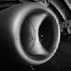
DocRob Posted May 24, 2024 Author Posted May 24, 2024 The engine is on it´s way and it is a bit fiddly, but due to great engineering and tight tolerances manageable. Adding all the V-shaped cylinder parts proved tricky, when the rocker came into play and the connecting tube (carburetor) needed to be added at the same time. Unfortunately, I mis-orientated this part and had to pry it loose later, which was no fun at all and caused some spots for later touch ups. Cheers Rob 10
Peterpools Posted May 24, 2024 Posted May 24, 2024 Rob Some mighty fine progress and just needing a few touchups is a major victory in learning the ropes for these types of kits. 2 1
DocRob Posted May 25, 2024 Author Posted May 25, 2024 16 hours ago, Peterpools said: Some mighty fine progress and just needing a few touchups is a major victory in learning the ropes for these types of kits. Thank you Peter, I simply hate touch up work. I always try to do everything right the first time, but of course sometimes fail, like here. The engine with all the added aggregates is quite complex, dozens of tiny holes need to be drilled and it´s easy to forget or misalign something when not fully concentrated. The toll of broken drill bits raises as well and soon I have to restock these. Cheers Rob 5
KevinM Posted May 25, 2024 Posted May 25, 2024 Looking good Rob and I hear ya about those bits last time in Mobile I bought like 5 that were .015" use them alot on the ship. 3 1
DocRob Posted May 25, 2024 Author Posted May 25, 2024 2 hours ago, KevinM said: Looking good Rob and I hear ya about those bits last time in Mobile I bought like 5 that were .015" use them alot on the ship. You can´t have enough of these buggers for a MFH build. I drilled dozens of tiny holes, the most complicating are the tube connectors, ultra small and need a centered 0,8 mm hole drilled out. I broke one or two bits per year with my usual modeling, but the Crocker made me brake three already. Cheers Rob 4
BlrwestSiR Posted May 25, 2024 Posted May 25, 2024 The engine looks great. Does this one have working internals (pistons and crankshaft) like some of their engines do? 1 1
DocRob Posted May 25, 2024 Author Posted May 25, 2024 1 hour ago, BlrwestSiR said: The engine looks great. Does this one have working internals (pistons and crankshaft) like some of their engines do? Thank you Carl, luckily there are no working pistons and other in that engine, it would make the construction even more complicated. Cheers Rob 2
DocRob Posted May 25, 2024 Author Posted May 25, 2024 I added more details to the engine and also prepared the distributor. Drilling the tiny oil tube connectors proved tricky. They need to be drilled to accept the oil tubing made from solder wire. Most of the screws shown on the casings are separate parts and also need to be pre drilled and then inserted. The manual suggests to add the oil tubes next, but I will do it later, because handling the still not finished engine would be a nightmare with the soft wiring on. Luckily the places for the tubing should be reachable later. I also added some dots of black panel wash here and there to enhance contrasts. Cheers Rob 9
Peterpools Posted May 26, 2024 Posted May 26, 2024 Rob Some mighty nice progress and I'm right with you in leaving off the solder made oil lines for as long as possible. Considering you still need to handle the engine and the odds are because they are so delicate, it's a disaster waiting to happen - the extra caution is the way to go. 2 1
DocRob Posted May 27, 2024 Author Posted May 27, 2024 On 5/26/2024 at 12:09 PM, Peterpools said: Some mighty nice progress and I'm right with you in leaving off the solder made oil lines for as long as possible. Considering you still need to handle the engine and the odds are because they are so delicate, it's a disaster waiting to happen - the extra caution is the way to go. Thank you Peter, with every step, the engine will be more and more difficult to handle. I guess only the distributor itself consists of more than a dozen parts. I managed to break off larger parts during handling, while correcting the carburetor tube. I guess, I not helped myself to easiest of MFH kits, due to the super detailed and part heavy heart piece engine. Cheers Rob 4
DocRob Posted May 28, 2024 Author Posted May 28, 2024 The last build sequence was a bit fiddly, with wiring the spark plugs with tiny etched parts and micro rivets, followed by the distributor, which consists of about 20 parts, a lot need to be pre drilled for various installments. There are two variants and I chose the more complicated. The magneto has a fewer parts count, but looks odd and the pictures I have of the real bike always have the distributor installed. I prepared the wires, but add them later, when the engine meets the frame. And that´s how tiny the distributor is, you find it on the left side of the engine, lower middle. Cheers Rob 9
HubertB Posted May 28, 2024 Posted May 28, 2024 Why do we have three spark plug wires exits, for a two-cylinders’ engine ? Enquiring minds want to know ? Hubert 2 1
DocRob Posted May 28, 2024 Author Posted May 28, 2024 32 minutes ago, HubertB said: Why do we have three spark plug wires exits, for a two-cylinders’ engine ? Enquiring minds want to know ? Pst Hubert, you discovered the secret, why the Crocker was so fast, the hidden third cylinder . The third wire leads somewhere into the front, but the manual does not show, where exactly. About the function, I have no idea. Cheers Rob 4
Peterpools Posted May 30, 2024 Posted May 30, 2024 Rob Amazing work ... delicate and absolute precision. 🏆 2 1
DocRob Posted May 30, 2024 Author Posted May 30, 2024 Thank you Peter, I have lots of fun working with metal for a change, but you are right, precision and a good plan are needed to tackle these kits. Cheers Rob 3
DocRob Posted May 30, 2024 Author Posted May 30, 2024 I built up the frame from it´s various parts, which again included lots of drilling and leafing through the manual, to see, which diameter is needed for a hole and what´s going in. Luckily the precision of the casting is fantastic and there are only minimal irritations in the parts. Here is a mock up with the engine mounted into the frame. Meanwhile said frame is primed and the missing carburetor parts got airbrushed. Cheers Rob 7
Martinnfb Posted May 30, 2024 Posted May 30, 2024 Found this nice picture showing the ignition coil lead and all the mysterious wires 6

Recommended Posts
Create an account or sign in to comment
You need to be a member in order to leave a comment
Create an account
Sign up for a new account in our community. It's easy!
Register a new accountSign in
Already have an account? Sign in here.
Sign In Now