CrankyCrafstman
-
Posts
1,350 -
Joined
-
Last visited
Content Type
Profiles
Forums
Events
Gallery
Everything posted by CrankyCrafstman
-

tamiya 1/32 mosquito color brochure???
CrankyCrafstman replied to CrankyCrafstman's topic in Modelling Discussion
Here here! -
tamiya 1/32 mosquito color brochure???
CrankyCrafstman replied to CrankyCrafstman's topic in Modelling Discussion
Cool, thanks Bir, PM on the way. Ron G -
Hey all anyone have this and are willing to part with it, or make a color copy for me, I'll pay for it and postage. I want to buy the kit but money is a little bit tight right now. Thanks Ron G
-
Re-starting HK Mossie
CrankyCrafstman replied to JohnB's topic in LSM 1/35 and Larger Work In Progress
OUCH! that sucks, but kids will be kids, still have to love em though. Ron G -
Re-starting HK Mossie
CrankyCrafstman replied to JohnB's topic in LSM 1/35 and Larger Work In Progress
If we do a group build can I use my 1/24 Mossie? Please Ron G -
Yep, mine are in the mail as we speak. Ron G
-
Small update Made a wing spar out of 0.06" thick black plastic. Put the dihedra at 1.40 deg. Or 1°24'10" inside of upper wing showing spar installed. inside of starboard upper wing. inside of port upper wing. I had to modify the nacelles to accept the spar, fairly easy. More later, waiting on some mister surfacer to dry so I can sand it smooth. Ron G

-
No problem Jeff all comments welcome
-
Cool, thanks Anthony. I'm going to use 0.005" thick plastic card and sand it almost away. Ron G
-
So Anthony should I leave it off? Ron G
-
Yeah Ernie, but they both have arthritis
-
Thanks Jeff, good to know
-
The preliminary report is in and it sounds like you maybe right Ernie. They found the #4 engine on top of the de-icing building with all three blades feathered and the #3 engine was found in the building with one blade feathered and missing part of the end from when it hit. Thats both engines out on the starboard comming in at three hundred feet and into a righthand wind. Not good! Ron G
-
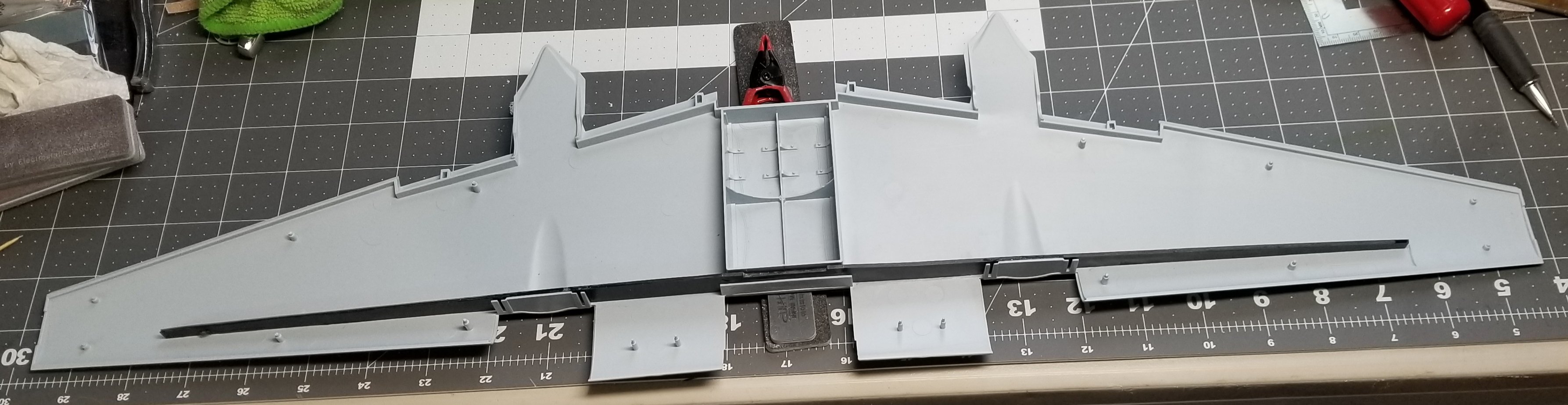
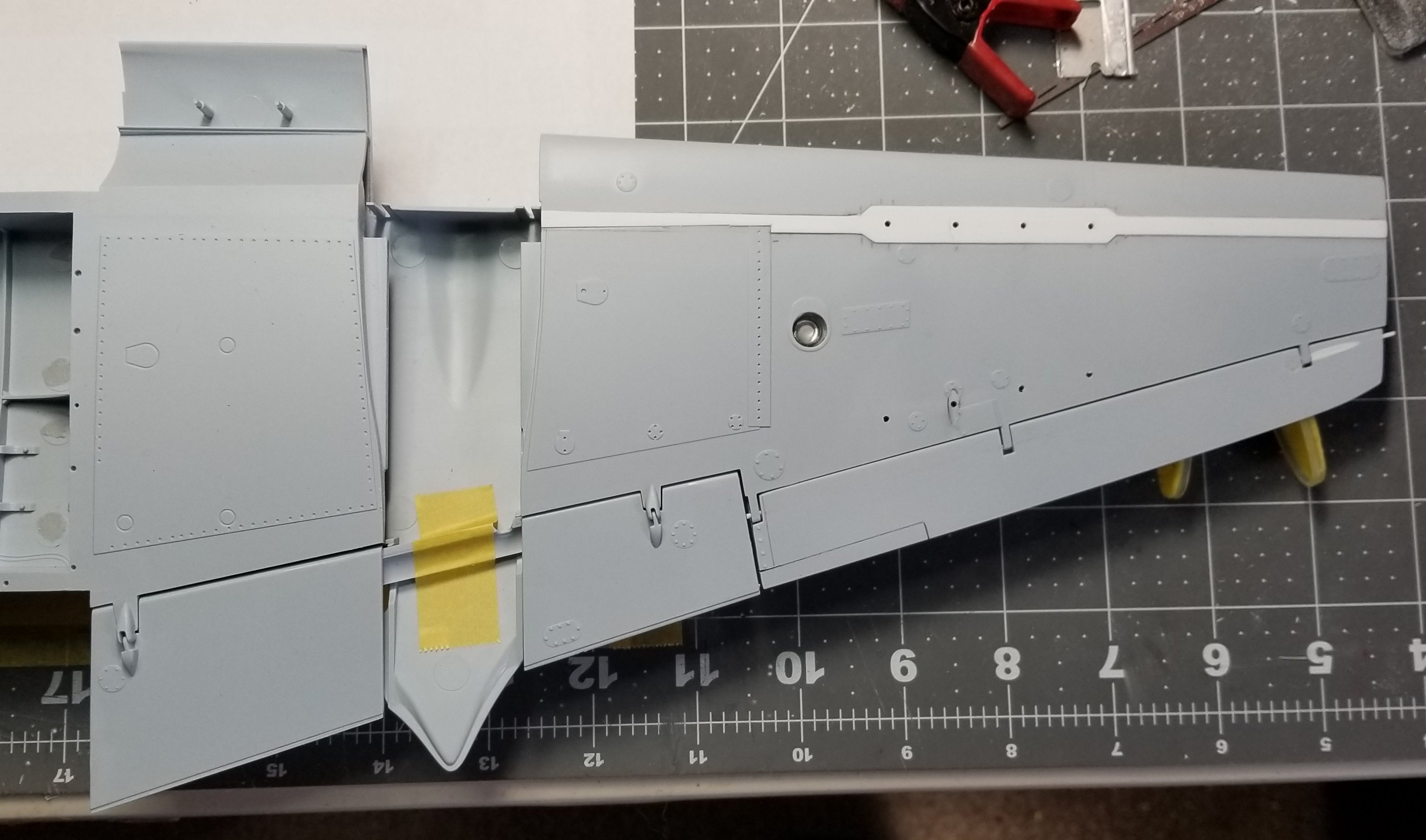
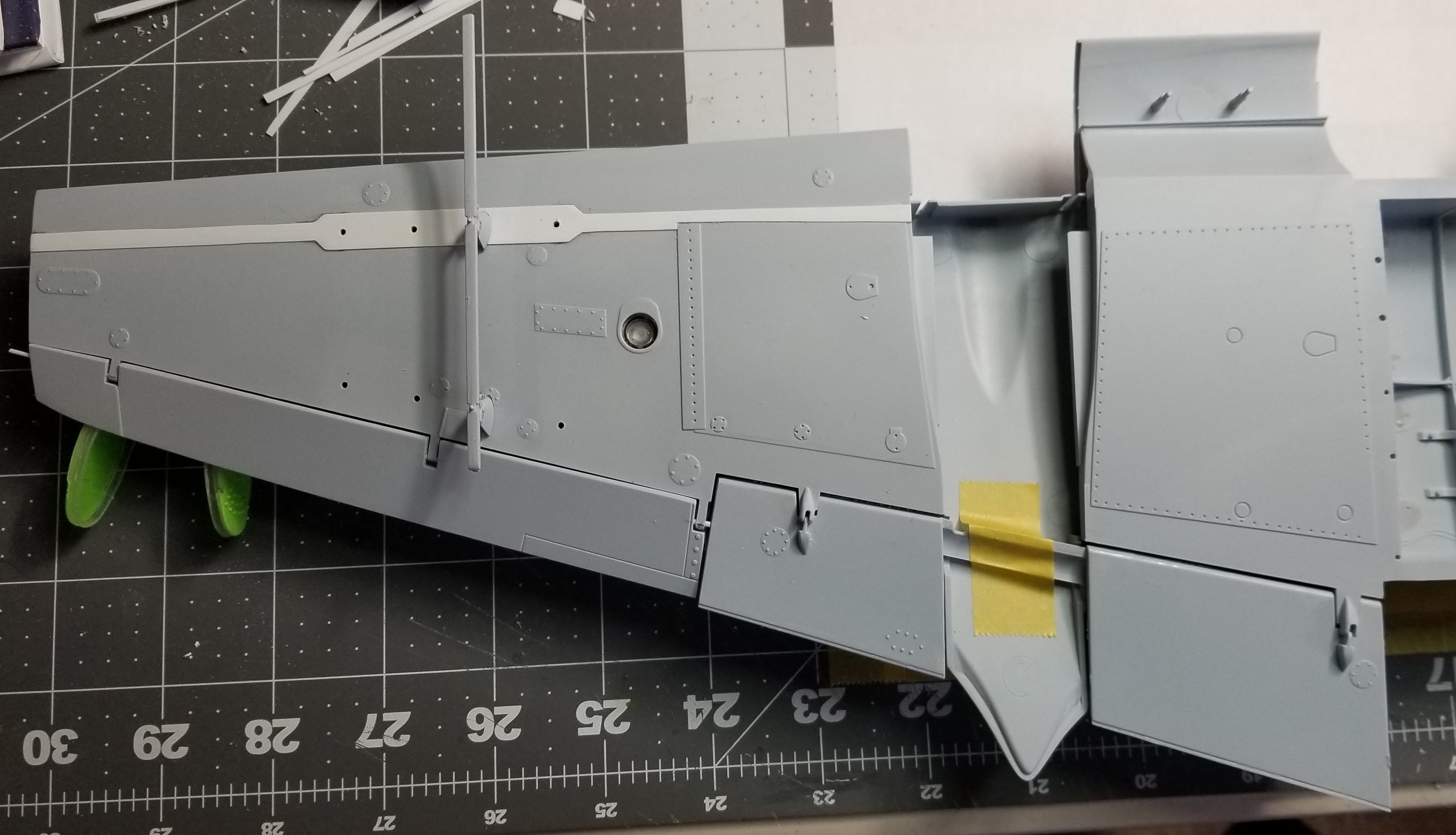
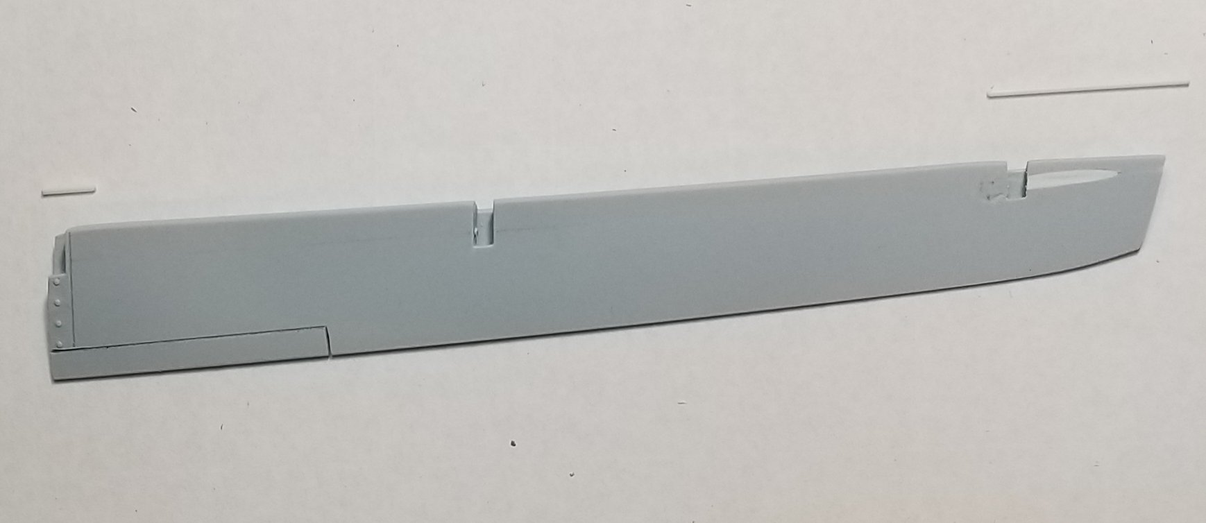
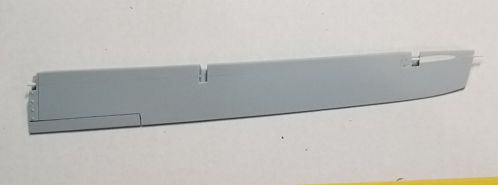
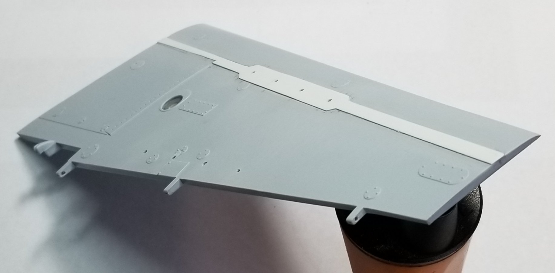
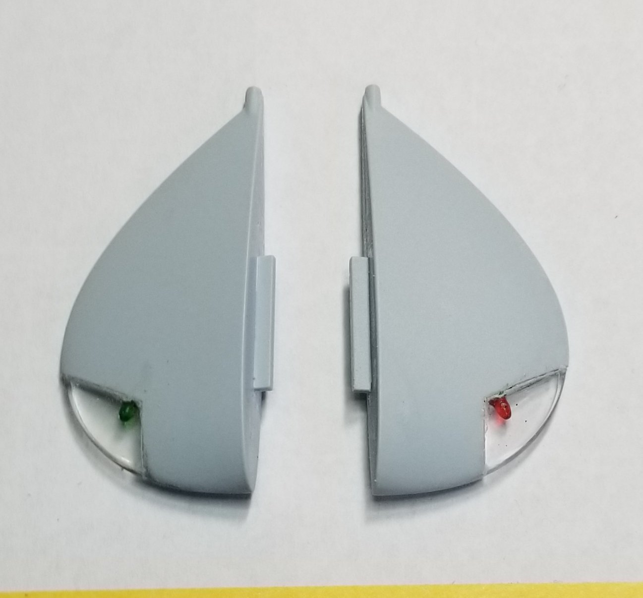
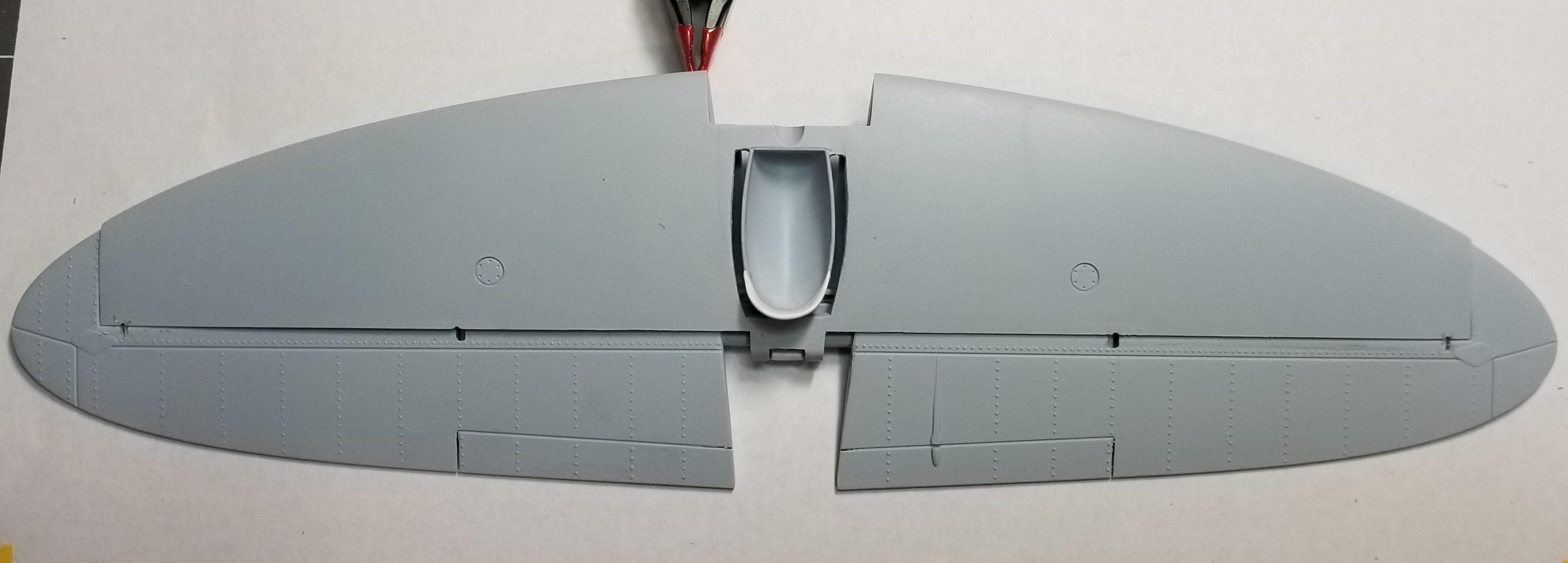
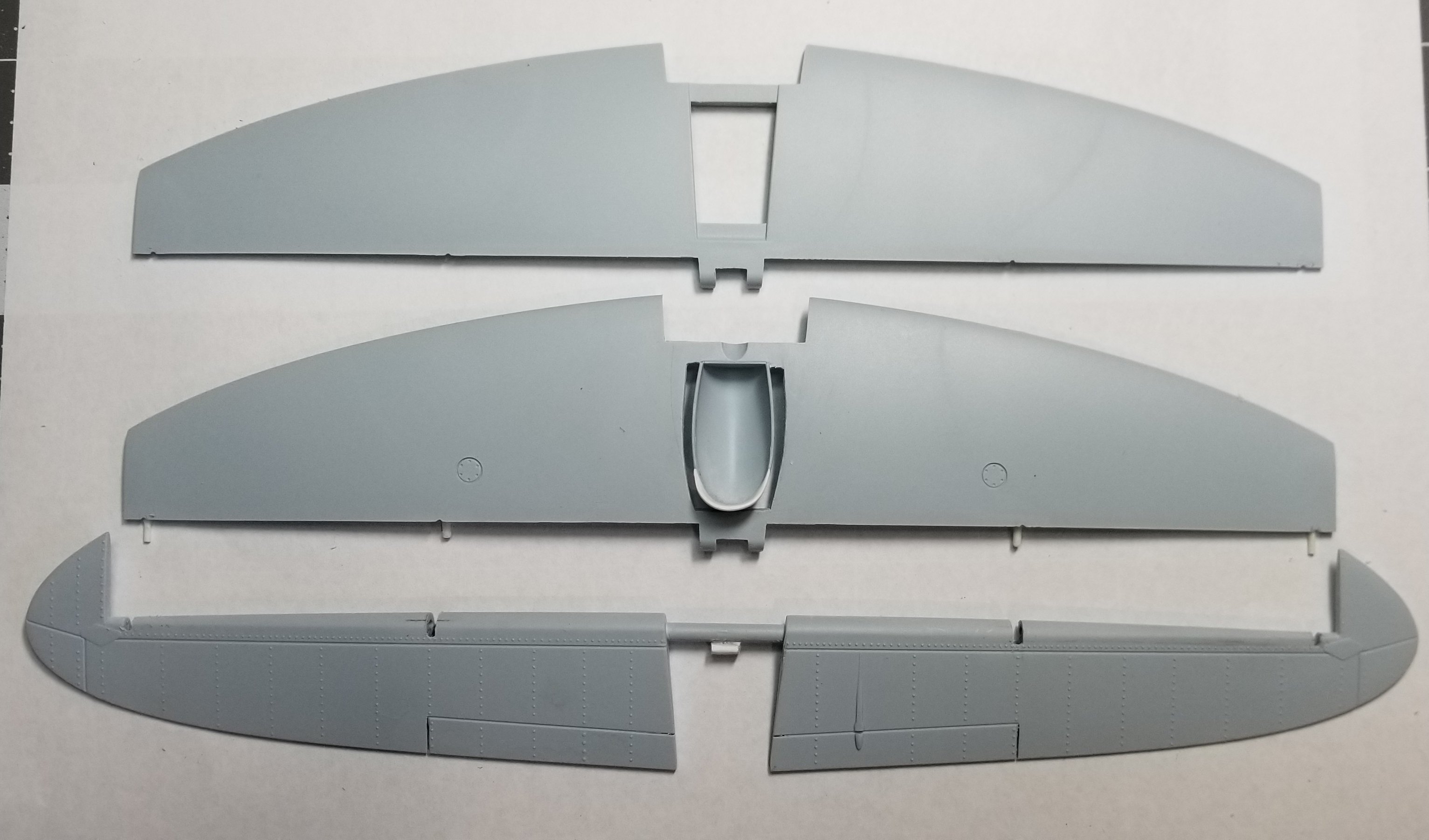
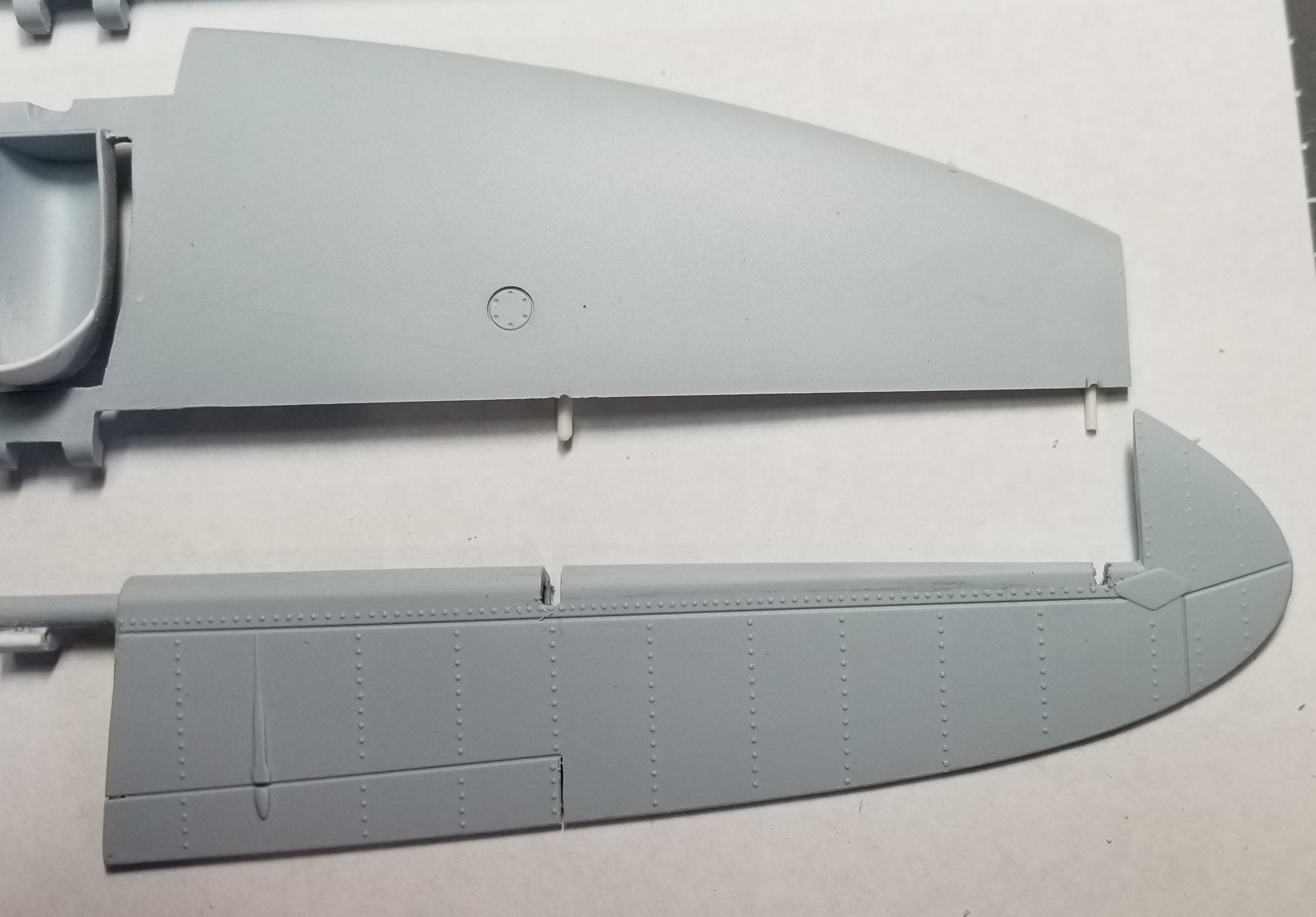
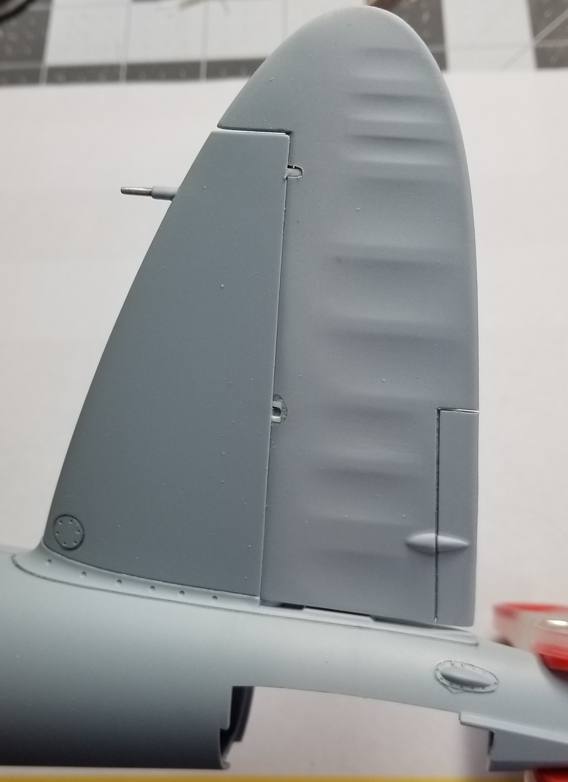
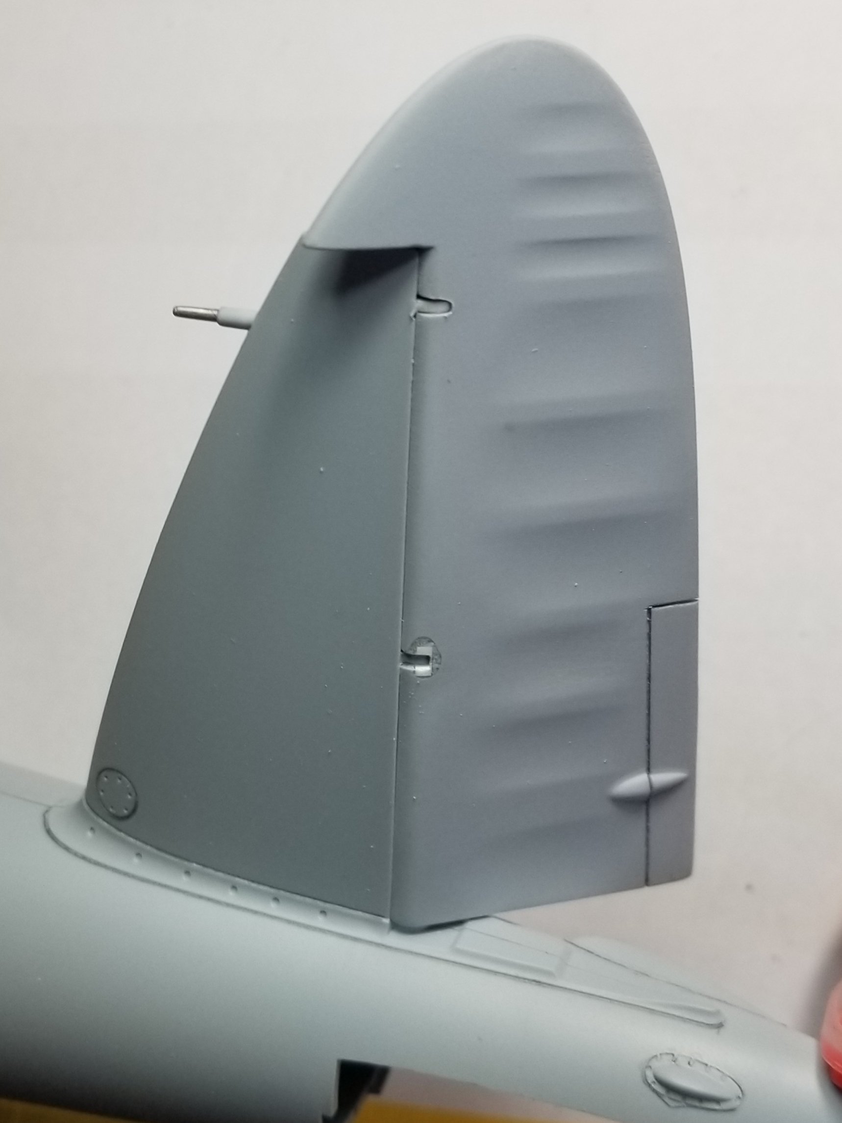
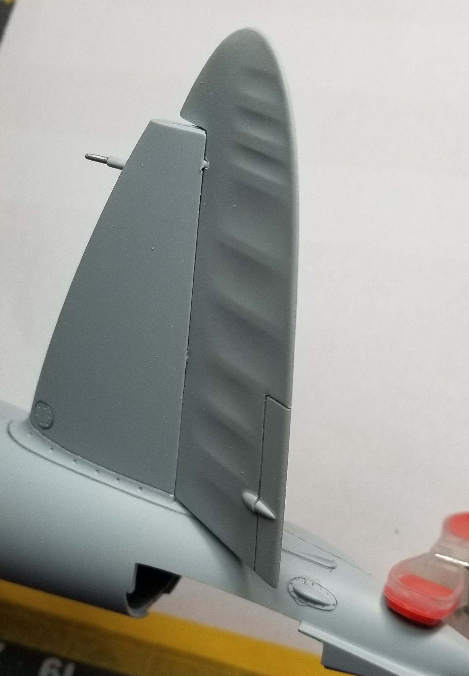
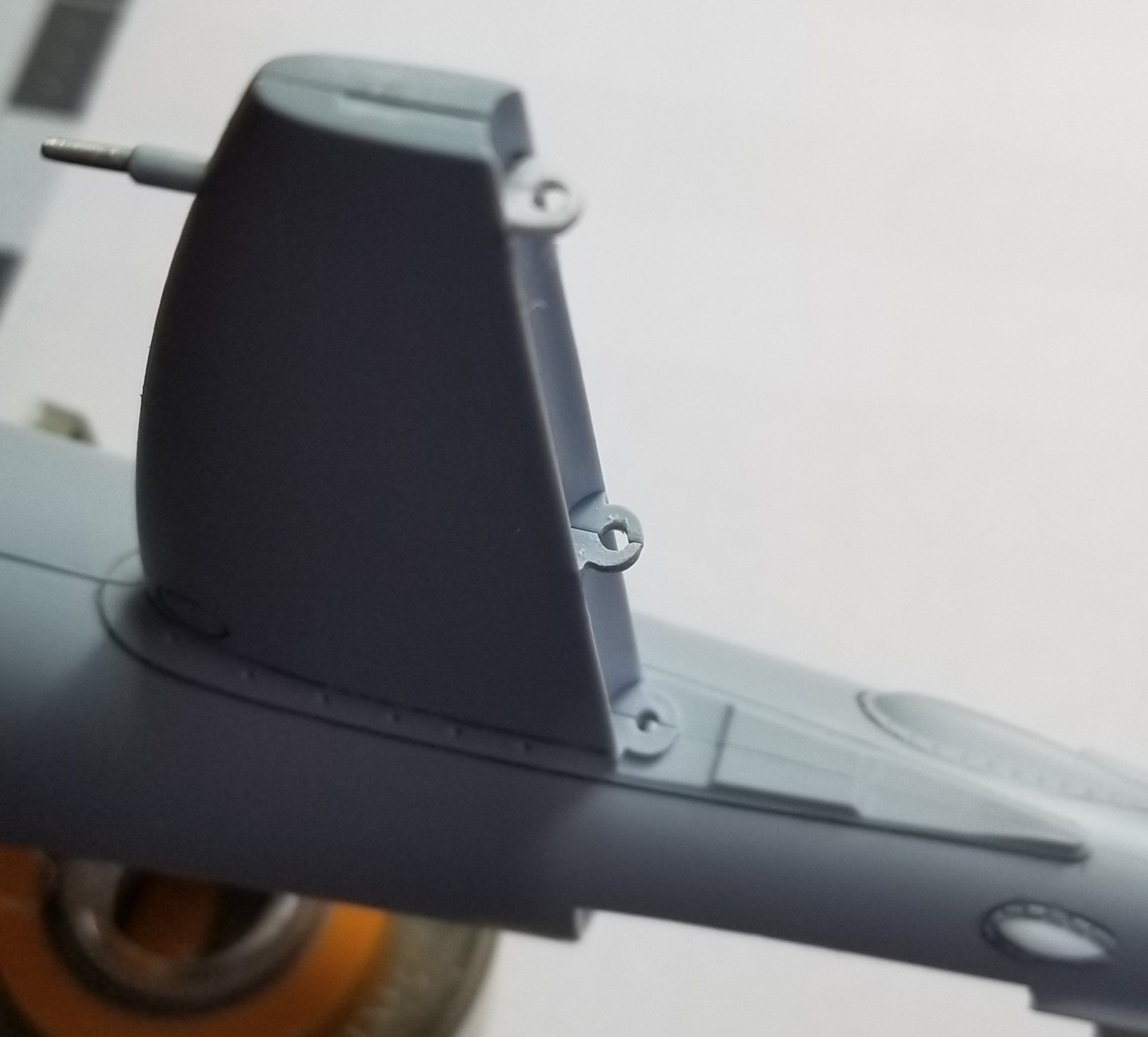
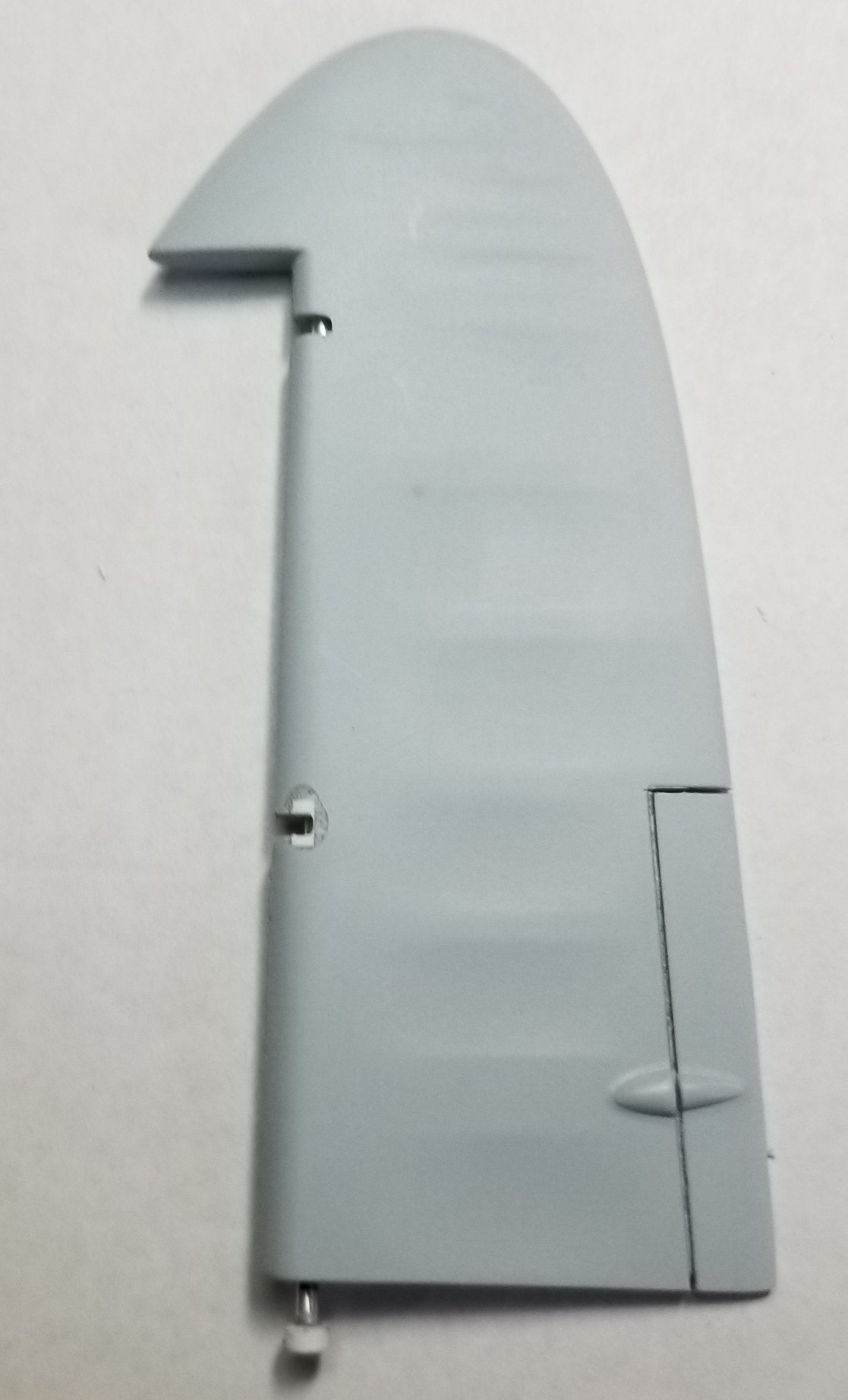
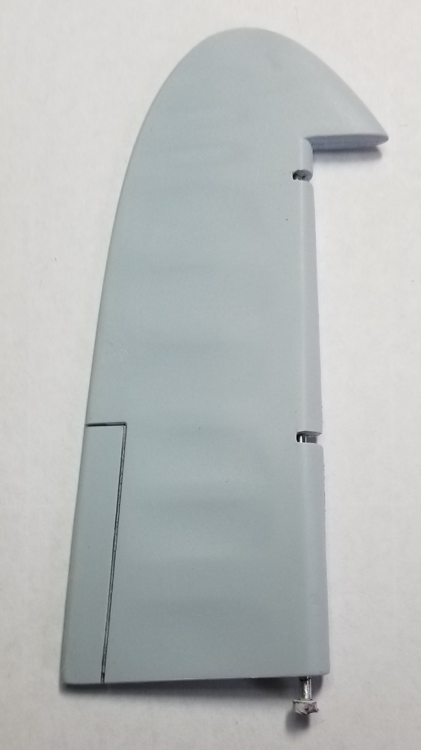
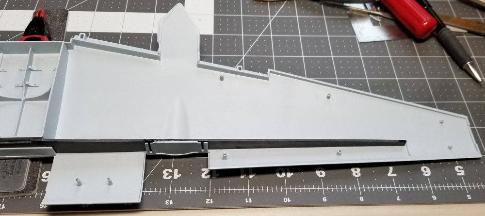
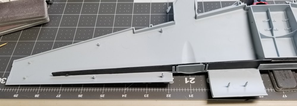
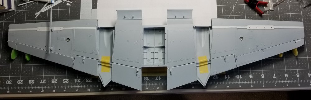
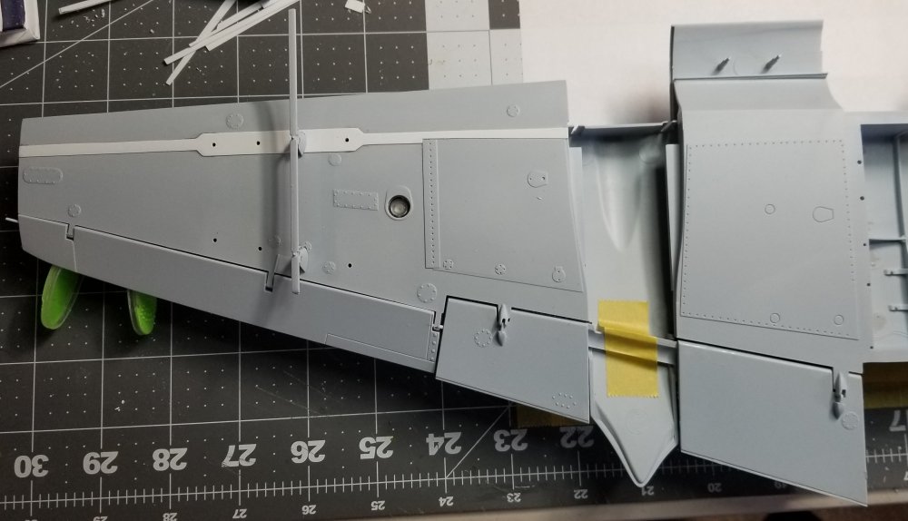
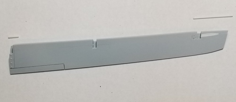
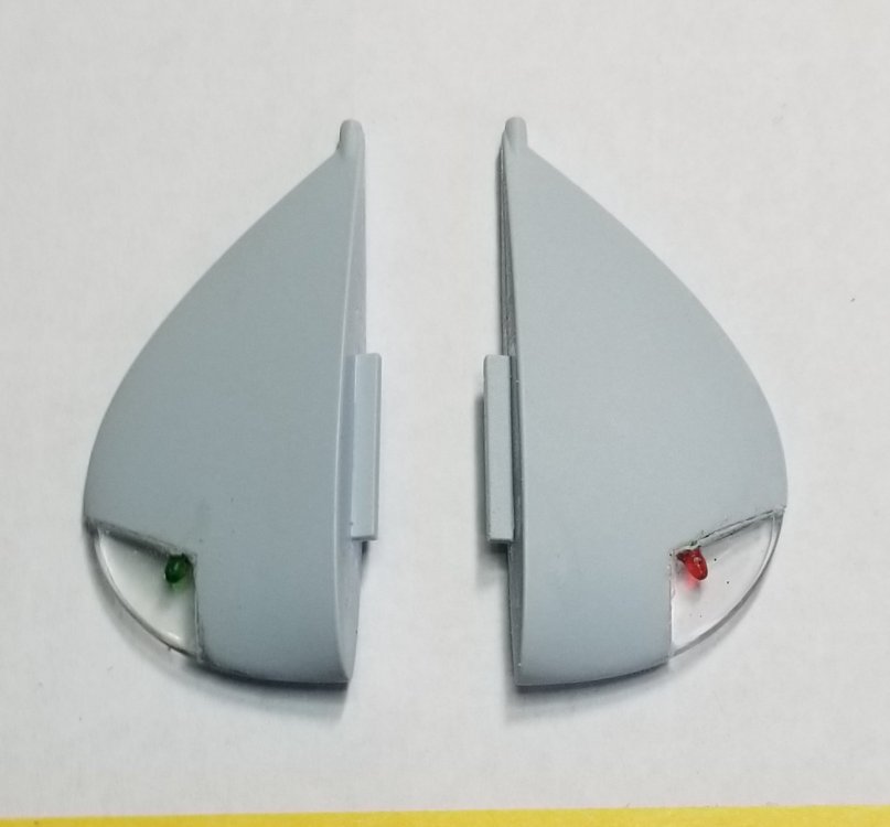
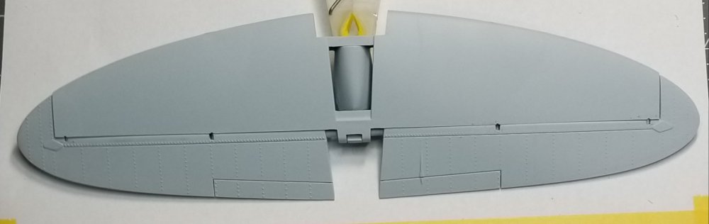
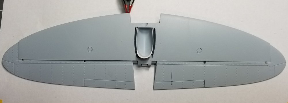
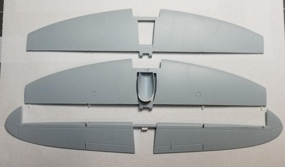
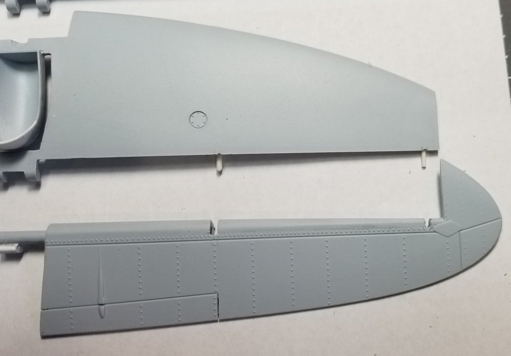
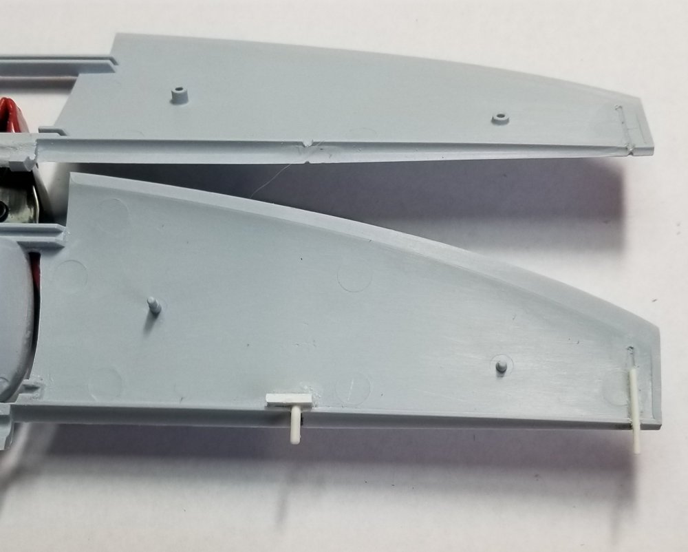
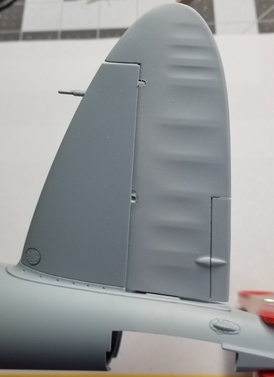
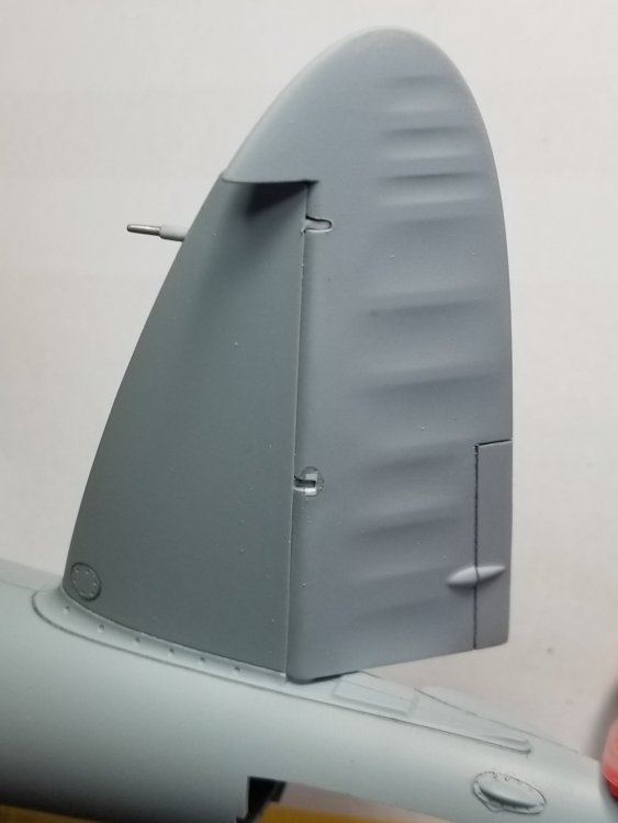
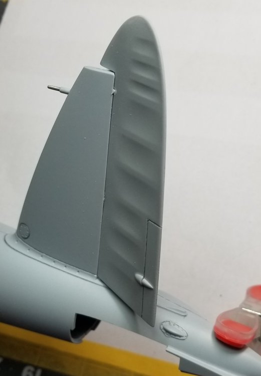
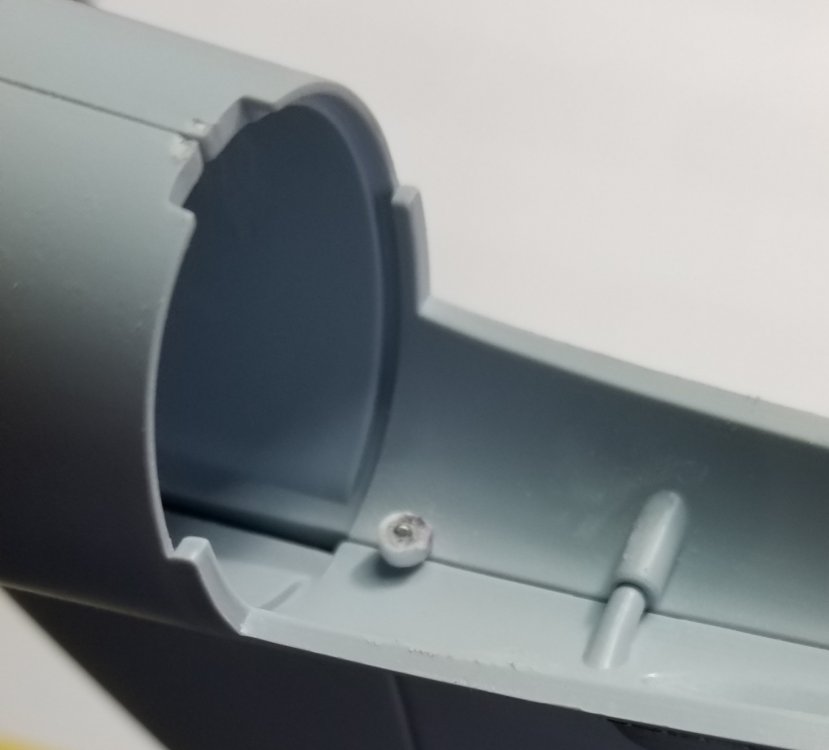
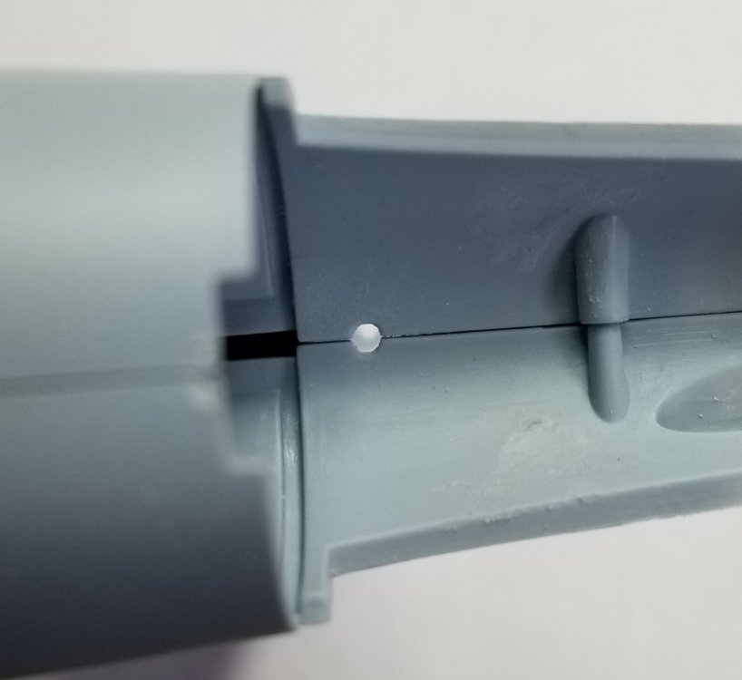
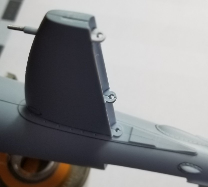
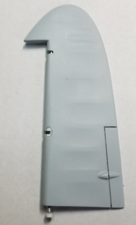
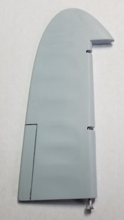
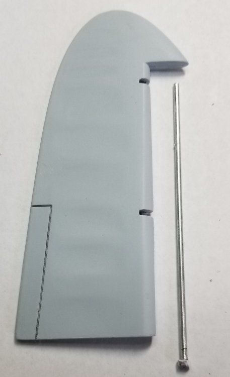
Hey all A little update on what I've been working on. I started working on the wings, rudder and elevators. I went through everything and altered them so that they work. I had a few mishaps, but everything worked out. Here are some pictures. I added the reinforcement strip cut from .015" plastic sheet. On the left you can see one of the rocket rails sitting in place. Everything is just sitting in place, nothing is glued yet. I still need to add the strip to the top of the wing. underside of port wing showing landing light, flaps (they need some filling on the rear edge) and the ailerons. At the right you can see were I drilled through the outer surface... but I managed to fix it. underside of starboard wing with one of the rocket rails. port aileron and the hinge pins made from plastic rod. 06" on the left and .04" on the right. port aileron with pins inserted in the drilled out holes. this picture shows the holes drilled in the hinges that the pins go in when you install the ailerons. wing tips with covers added and bilbs made from 1/16" colored acrylic rods cut to size and coat with a light coat of Tamiya clear red and green. top of tail planes assembled. bottom of tail planes showing the tail wheel guard drilled and cut out and rear of guard extended, thanks to Anthony in NZ's build. view showing parts apart. bottom view of port elevator and tail plane. You can see the cutouts made to clear the hinges that I made from plastic rods. view showing plastic rod hinges. view showing rudder in place. view showing rudder to the right. view showing rudder to the left. view showing the bottom of the rudder hinge pin. view showing hole for hinge pin. view showing holes for hinge pin. I had to reolace the upper hinge cause it broke off when I was test fitting the rudder. port side of rudder, you can see were I f'd up on the center slot. Hinge pin shown installed. view of starboard side of rudder. view showing rudder and hinge pin made from steel rod and aluminum tube. Well that's as far as I have gotten on this beast up to now. I've test fit all of the wing, fuselage, rudder and nacelles and everything seams to fit pretty good. But we'll see how it goes when it gets to gluing it all together...knock on wood Ron G


-
Trumpeter P-47D Razorback
CrankyCrafstman replied to crazypoet's topic in LSM 1/35 and Larger Work In Progress
You are correct, they were a braided wire, similar to what was used on automotive engines of the time, but of a much better quality, better noise/ static suppression. Ron G -
7 dead...there were 13 on board, the Pilot, Co-pilot, flight Engineer and 10 passengers plus one person on the ground. I think Ernie my prove to be right, because it sounds like he touched down and tge veered off the runway to the right into the de-icing shed. Ron G
-
Hey all Sad news today. The Collings Foundation B-17 has crashed in Connecticut. this happened October 2, 2019 at approximately 9:00 am. There were 7 people killed. There were three crew members on board with I believe 10 paying passengers, plus one person on the ground involved. They had just taken off when they experienced engine problems and turned around to land and check out what was wrong when they crashed into a building on the runway area by the de-icing facility. From the videos it's hard to believe how anyone could have survived. I hope they don't stop these flights because of this, because there is already talk about how safe these old WW2 planes are, sad very sad Ron G
-
Trumpeter P-47D Razorback
CrankyCrafstman replied to crazypoet's topic in LSM 1/35 and Larger Work In Progress
I went through the P &W R-2800 book and did not see one photo or discription that said/showed they had tubes for spark plug leads. They had a pressurized ignition ring but not the plug wires. Plus they all didn't have pressurized ignition systems. Ron G -
Ok, thanks again Anthony
-
Thanks Anthony Actually I finished them Friday evening, before I got your photos, but thanks they helped to refine my plans. Hey did you ever find those Paragon exhaust shrouds? I could sure use em if you got em. This thing is a huge drain on ones modeling mojo, and I know you get what I mean.
-
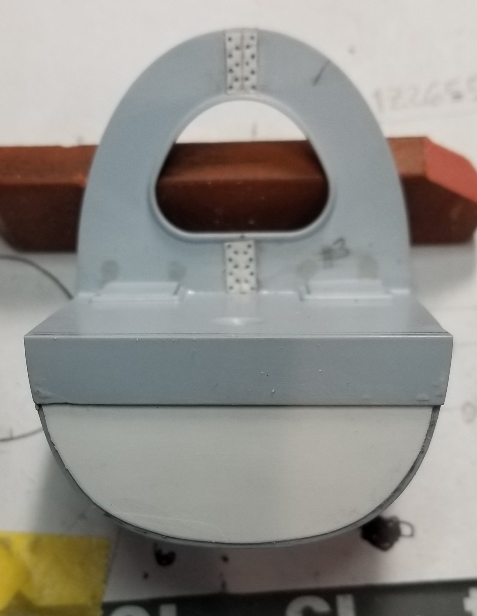
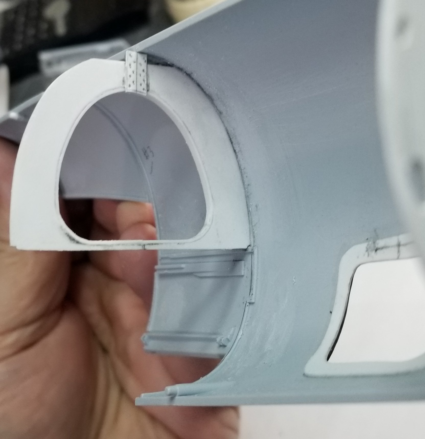
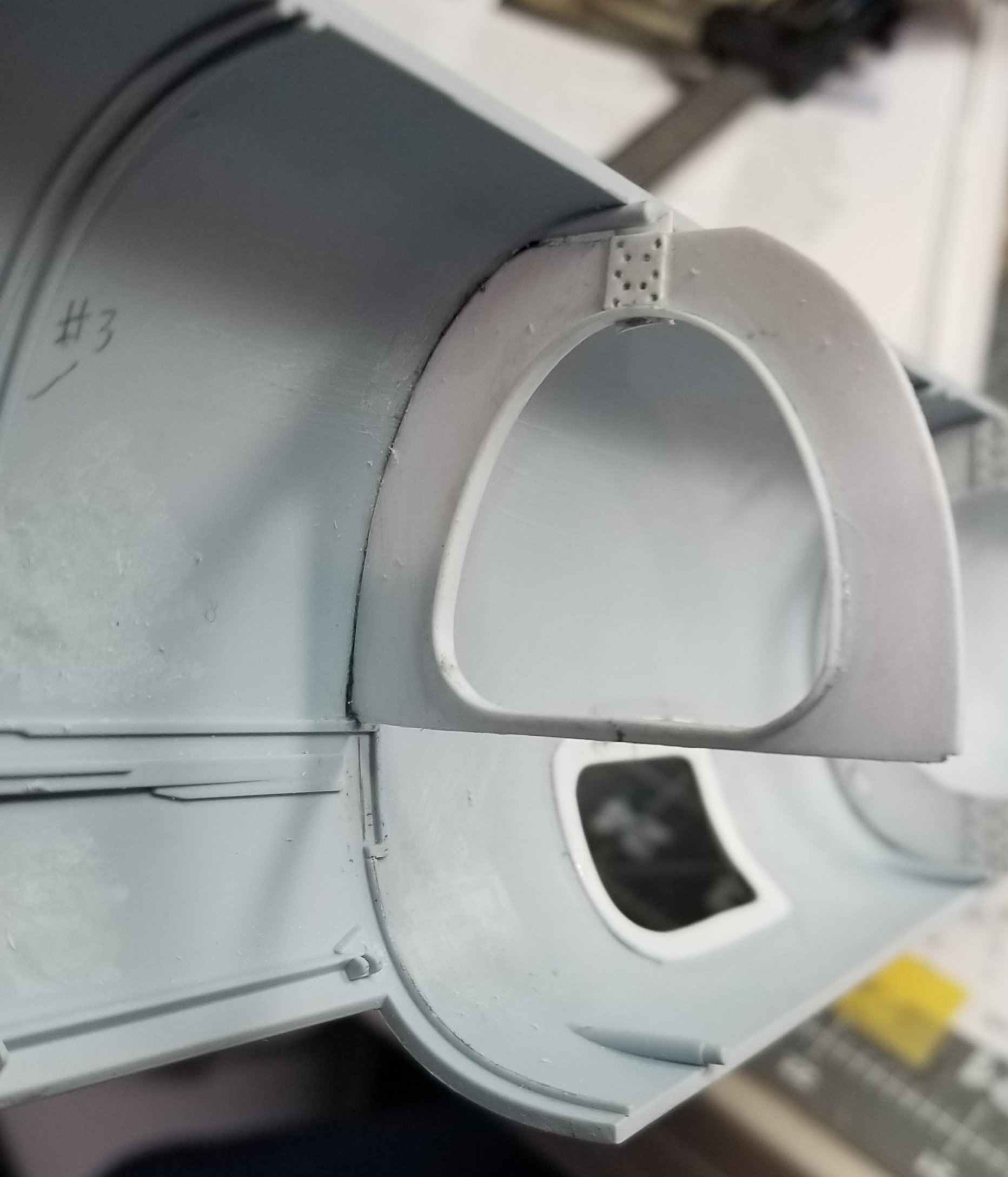
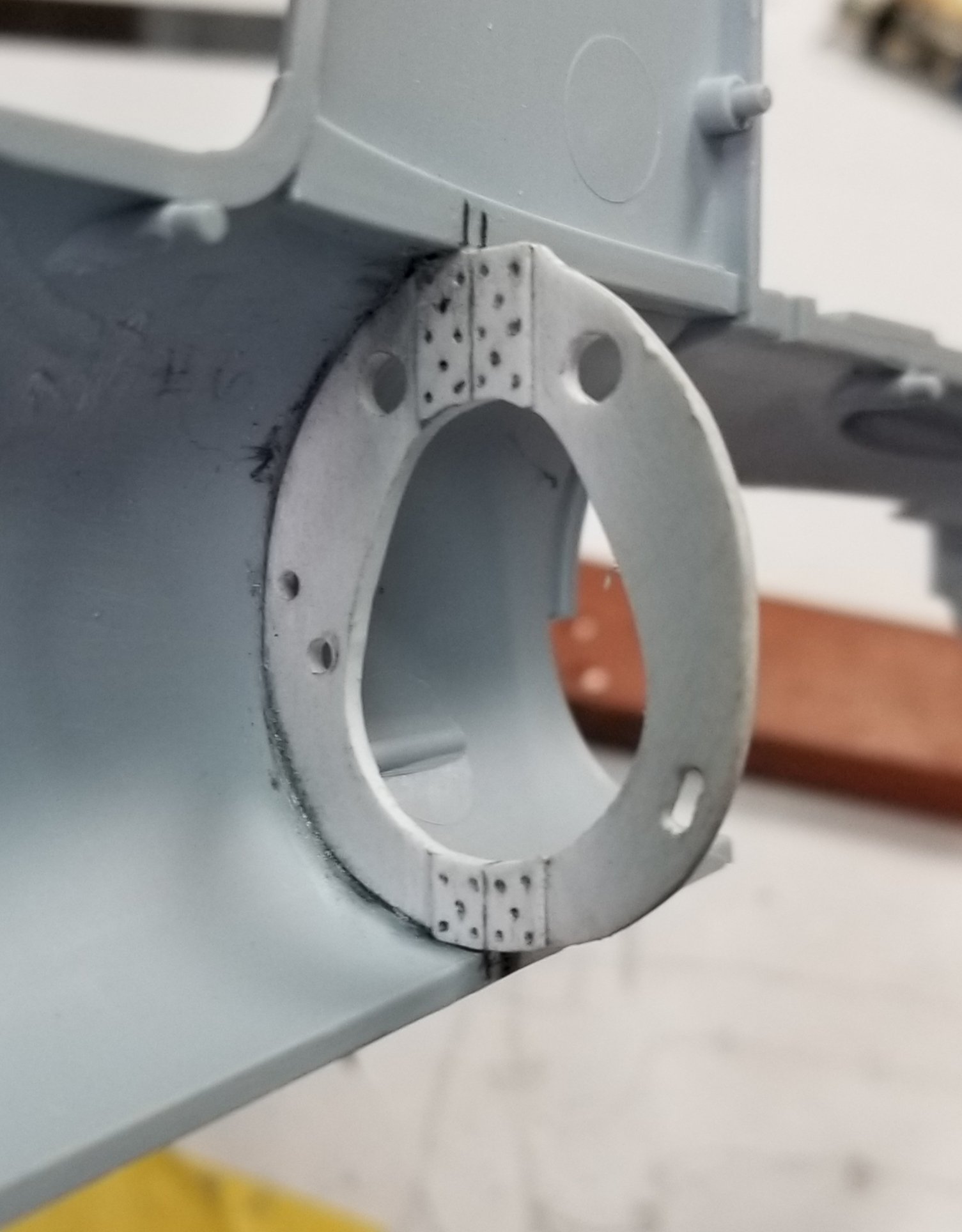
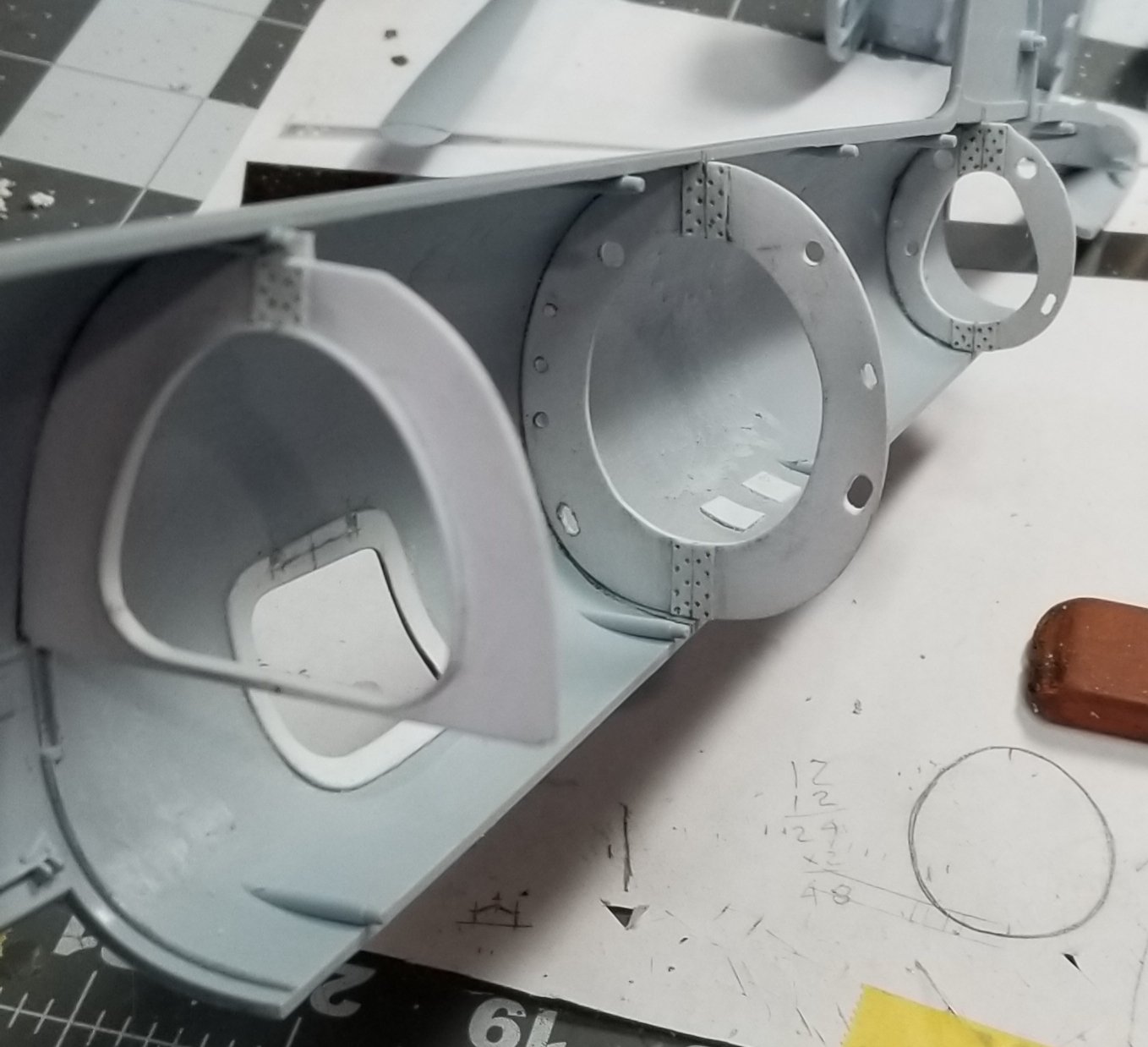
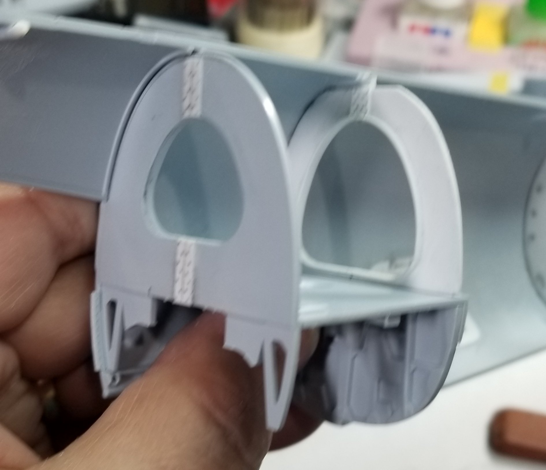
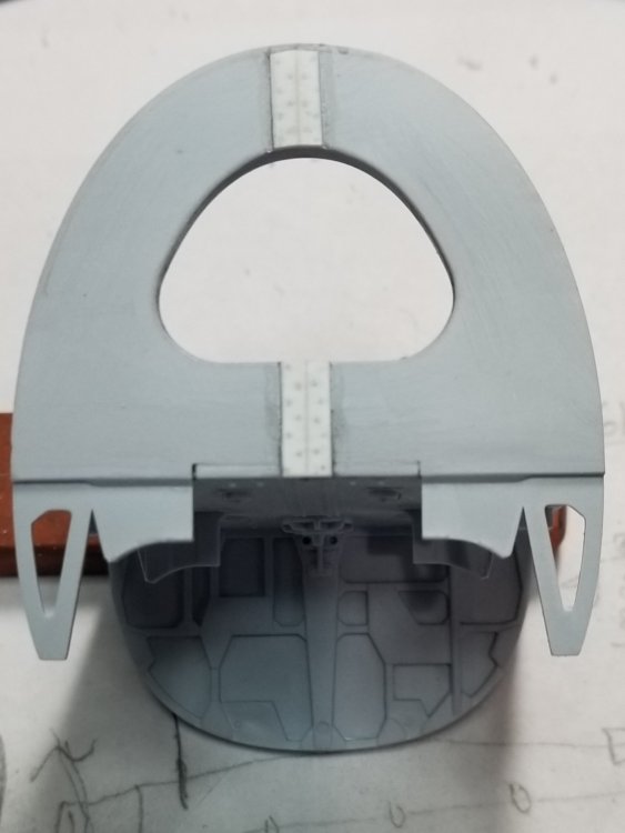
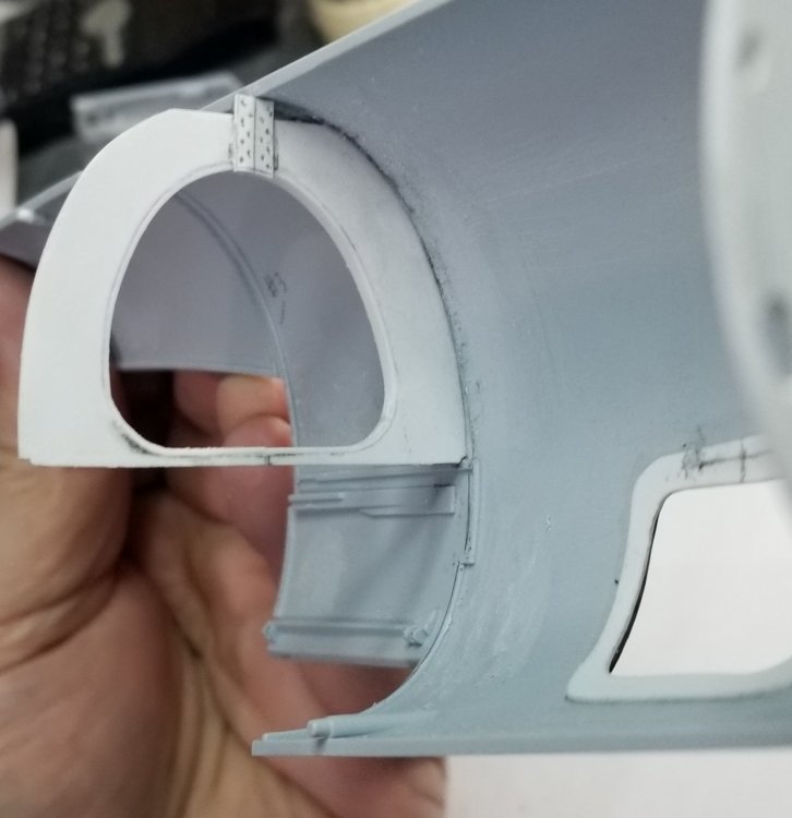
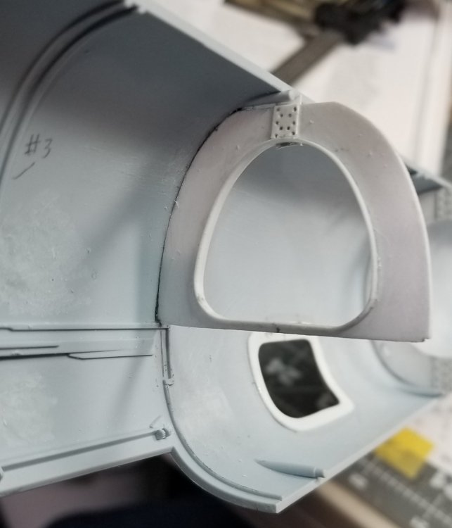
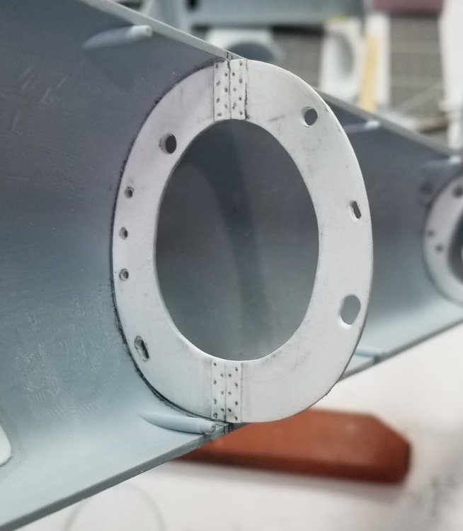
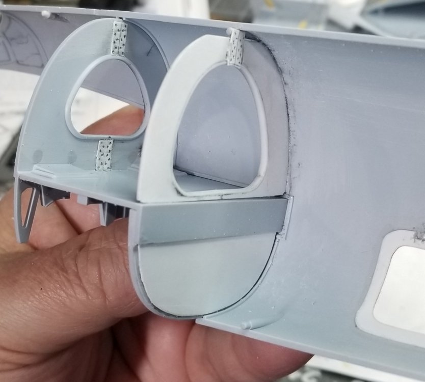
Some more progress on this beast. I decided to add all of the bulkheads from 1 through 7. Bulkhead 1 comes in the kit, 2 comes in the kit, 3 comes in the kit, 4 only has the lower half in the kit so I made the upper half of it. 5 is totally from scratch, 6 is totally from scratch and 7 comes in the kit. Here are some pictures. This is the rear of bulkhead 3 and lower portion of bulkhead 4. I added the two white peices of plastic card to represent the attachment plates that held the two halfs of the fuselage together. This is the front of bulkhead 3 and the added plates. This is bulkhead 4 upper, I added the plate and the inside of the cutout is lined with a piece of 0.015" thk. x 0.08" wide plastic card. Similar to what is on bulkhead 3. Front view of bulkhead 4 showing the added plate and card stock rib added to the cutout. This is bulkhead 5 with the added attachment plates. This is bulkhead 6 with the added attachment plates. This view shows bulkheads 4 upper, 5 and 6. this is a view looking forward at bulkheads 4 and 3. You can see how my part fits to the kit parts. I also added a piece of card to the lower half of the back of bulkhead 4. View looking rearward through bulkheads 3 and 4. View showing the top of the fuselage joint, not to bad of a fit. This view shows the fit of the lower fuselage. View looking into the rear radio hatch. A view looking down through the fuselage. This will all be covered up, but I will know that it's there. Thanks for looking let me know what you think. Ron G


-
Hey Charlie are you sure you want me to bang it on the ground? Ron G
-
Trumpeter P-47D Razorback
CrankyCrafstman replied to crazypoet's topic in LSM 1/35 and Larger Work In Progress
Looking good Crazy Ron G -
So, what's on your floor tonight?
CrankyCrafstman replied to [CAT]CplSlade's topic in General Discussion
ALOT of Golden Retriever hair!!! Have to remember to block entrance to hobby area. Ron G -
Yes I have Definitely thinking about those for the Mossie or the Typhoon. Ron G