
HubertB
-
Posts
2,990 -
Joined
-
Last visited
Content Type
Profiles
Forums
Events
Gallery
Everything posted by HubertB
-
Well, this is the going price as long as the seller finds a buyer for it … I never bought a kit for investment and future resale. Otherwise, I wouldn’t be butchering my Fisher Cutlass (which is the bottom box pf a significant pile of white boxes of the same manufacturer). But I reckon I have some rare kits, and my stash is probably worth - in total - the price of a (small) entry-market car … But I’ll live long enough to finish them all ! What’s 250 years after all ? Hubert
-
 Not bad at all for a kit that is more likely 60 than 50 years all 👍. At that time, there was no 3D design software, no CNC machining, no spark-erosion machining. Just a hand-made master, and a pantograph to scale it down to the steel mold. One wonders why modern kits with all the tech available are sometimes not able to match these oldies … Thanks for the nostalgia trip Hubert
 -
Gotta say the light blue looks a little weird, IMHO at least … Hubert
-
+1 ! Hubert
-
Sikorsky JRS-1 with AM (Eduard) 1/72
HubertB replied to Landlubber Mike's topic in The Great Twins Broup Bluild
Great work on the landing gear 👍 ! I concur on the greatness of the Albion Alloy tubes and rods. I have a supply of them always available. Just a tip : Tamiya pink primer ( yes, Barbie pink) is a great base for yellow / chrome yellow wings. Hubert -
Hubert
-
Looks good to me: we have the sand, and we have a « subject » Hubert
-
Maybe too late for the offer, thanks to the jet lag, but you can have my Sparrows, which look good with no warped fins. Just PM me your address and they are yours. Hubert
-
I still have to find a better alternative to Micro Foil Adhesive, but have not so far. One important thing : Micro Foil adhesive can be thinned (a lot) with alcohol. I then brushed it on the part to be foiled rather than the foil. But, yes, the thicker the foil, the better, when you want to burnish it on compound curves. Hubert
-
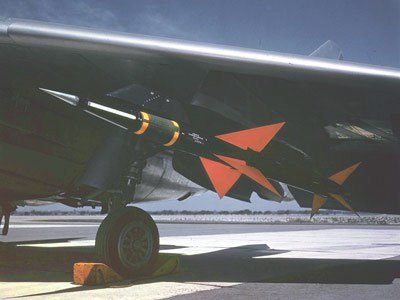
Mine will be sans missiles …but with the pylons. Btw, Fisher has done an excellent work on the Sparrows Mk1, but they had a pointy, straight cone nose. Fisher’s Sparrows have a too rounded nose, if you want to be accurate. Hubert
-
Need to go back to my references, but, from the dates the Thunderbirds flew them, and the pics I remember, I’d say they were NMF, not silver-painted … Hubert
-
What I know is the F-105 started with a real NMF, then, as a corrosion guard were painted silver. I do not know for the F-100, or F-86, but would assume it is a likely possibility .. Hubert
-
Well, as the dice seem cast, and to broaden the spectrum from the expected « Afrika Korps / MTO » subjects, I found this interesting site, with hundreds of pictures from 1919 to the 70s, where sand is really a big component … https://aviation-algerie.com/aviation-algerie/ Just scroll down the list of topics (titled in French). There are literally hundreds of them, each with about 40 pics. And, yes, you can even model a Bréguet 961 « Deux-Ponts » in 1/32 (or 1/48 ), courtesy of « One Man Model » in Japan (although his eBay store does not seem active nowadays) .. HTH to bring some additional inspiration, and, to add ideas, thanks to Mark31, « May the Force be with you » ! Hubert
-
Isn’t « Sandbox » the right theme then ? Hubert
-
So Martin, Have you made the choice (although the poll is quite clear ) ? My only remark is about the deadline. 4 months is short, for most of us - and even more for me with a lead time that counts in years rather than months 🤣) Hubert
-
1/18 Hawker Sea Fury - probably VX620..
HubertB replied to airscale's topic in LSM 1/35 and Larger Work In Progress
C’mon, Peter, we know you are an outstanding modeller. No need to post pics of the real A/C landing gear bays and pretend it’s your work . Show us your real work, we’ll be kind to you. I promise … Hubert -
Roden 1:32 Nieuport 28c1 build
HubertB replied to AOE4's topic in LSM 1/35 and Larger Work In Progress
Hello and I don’t think you will get the same result using brass strips and flattened tubes, as Rob suggested, especially in terms of rigidity. Flattening a tube is easy, by holding it in a vise, and slowly closing the jaws of the vise. Albion Alloys used to have a special jig for that, but it’s now in Unobtainium Land … To control the thickness of the flattened tube, you can insert a much smaller diameter brass rod in the tube, and make it slightly longer than the tube. This way you will obtain constant thickness struts, and with positioning pins on top of it. To obtain for example a 3 x 1 mm strut, you should be OK starting with a 2.5 / 2.6 dia tube. HTH Hubert PS: make sure the jaws of your vise are smooth, not striated. That was the interest of the AA device … -
Well, thanks for the tip, Chris. I am usually wary of drawings, as they can sometimes induce some mistakes, and most of these are no exception. But it yielded some pics of the plane I intend to model, which I had not found hitherto, and will prove invaluable 👍 ! Hubert
-
1:32nd scale Phönix D.I
HubertB replied to sandbagger's topic in LSM 1/35 and Larger Work In Progress
I just love the Lukgraph kits. High quality, and on top of it, my kind of subjects. As usual, I’ll be taking a seat o watch the Master at work Hubert -
There are seven surviving airframes, most of which have been used as gate-keepers and have rotten consequently. The pics I posted are from a F7U-3 displayed at the NASM in Pensacola, and features many bogus features and / or missing components. It’s (wrongly) tagged as a F7U-3 M. I have used other pics for some detailing, like the landing gear bay, of BuAer 129554 (a F7u-3), which was supposed to be restored to flight condition. It has changed hands many times, and is now in Phoenix, AZ. I don’t know if it will ever be finished to flightworthy condition, bur whereas the hydraulic system could be updated to modern standards, and thus alleviate one of the main issues that plagued the Cutlass, the question of the engines would remain, and of the fragile front landing gear strut … It’s still the most reliable source for detailing the kit Hubert
-
Cobra Coupe - Le Mans - Model Factory Hiro 1/12
HubertB replied to DocRob's topic in LSM 1/35 and Larger Work In Progress
Wow ! Stop teasing and tempting us, Rob Hubert -
Not a lot of apparent progress to report, but some I feel pretty smug about... A bit of background. Fisher seem to have completely forgotten one aspect of the Cutlass, that is the device that holds the arrestor hook in place (or if it was included, it is not in the parts I have, nor apparently in the instrcutions, but then some small details have been overlooked in the said instructions). This is what it looks like IRL. The photos are lifted from an IPMS NL walkaround, but beware that the F7U-3M displayed seems to have been cannibalised, or vandalised, over the years, and not every component is still present on this airframe. And this is my rendition of it, adding a few pieces that seem to make some mechanical sense, but are apparently not on the walkaround pics. The whole is less than 1 cm long, if you wonder ... I quite like my springs, made from 0.2 mm tungsten wire coiled around a 0.5 mm brass rod A few hours' work, not perfect, especially the alignment which is slightly off, but "good enough for govenment work" as the saying goes. In the meantime, I have started repairing the rear of one wing tip, which has been damaged in all the handling the Cutlass has endured so far. And the fins are now glued in place. Next should be mating the front and rear of the bird. TTFN Hubert.
- 164 replies
-
- 11
-

-

-
Yes, the B-68 had underwing positions, and they were for « special weapons », which are represented by Monogram / Revell. You apparently created for yourself a set of problems by going for an in-flight display … but I am sure you will prevail in the end. For me, the B-58 looked like it was doing Mach-2 even on the ground on its spindly landing gear, so I always loved its highly complex landing gear. As for the scheme, it was never meant to drop anything else than « special weapons », so a SEA scheme seems incongruous. But then, it’s your build and you can do as you want. I have taken a seat to watch your progress Hubert
-
Absolutely gorgeous, Kris ! Hubert
-
I read your report, Officer, and against all my hopes, I realised this was a deliberate act of sabotage ! And against a war asset of His Majesty ?? !!!! You know what the outcome to this is, don’t you ? Hubert