Axeman
-
Posts
172 -
Joined
-
Last visited
Content Type
Profiles
Forums
Events
Gallery
Everything posted by Axeman
-
I got one of the last wing nut wings from Andy’s Hobby Headquarters last October. I have never built one and I am looking forward to it. Tim
-
Thank you for the encouragement. Not much work today and tomorrow afternoon. Taking my son out to dinner for his 21st birthday. I might get a little more done Sunday night. Fingers crossed. Tim
-
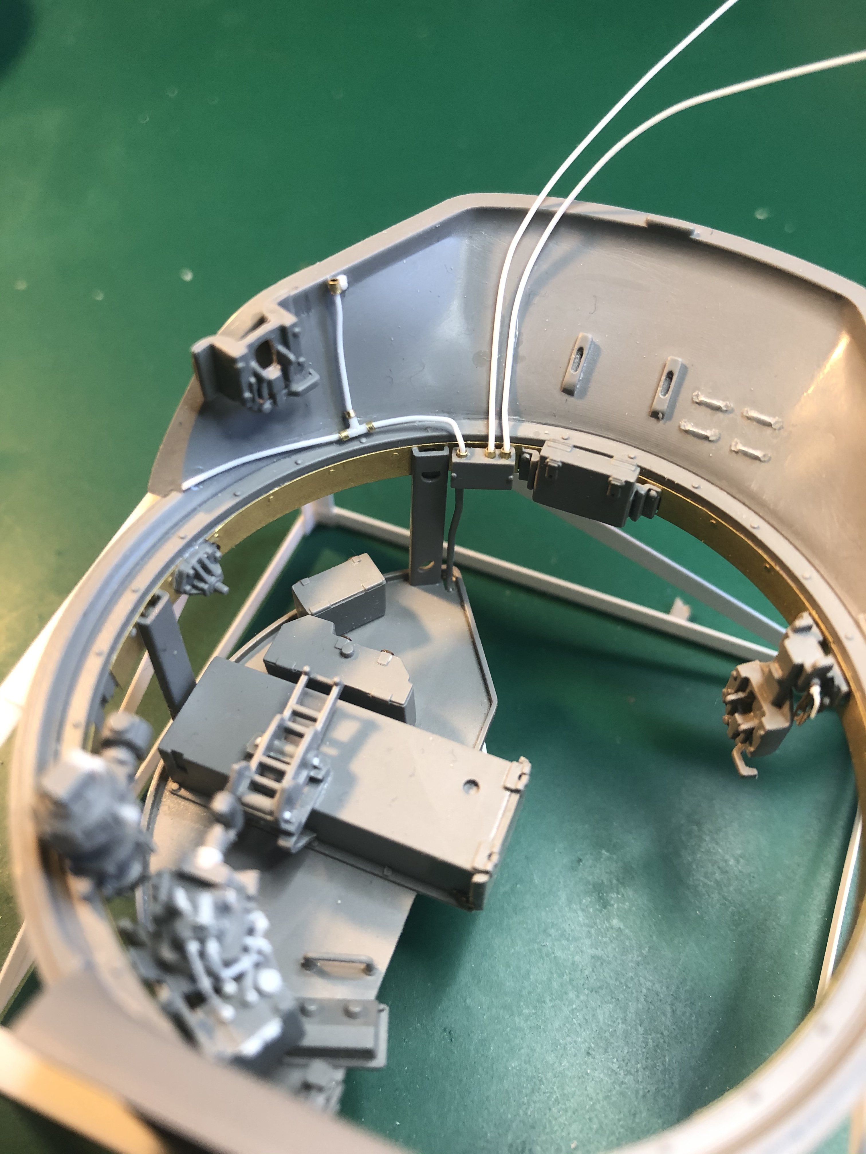
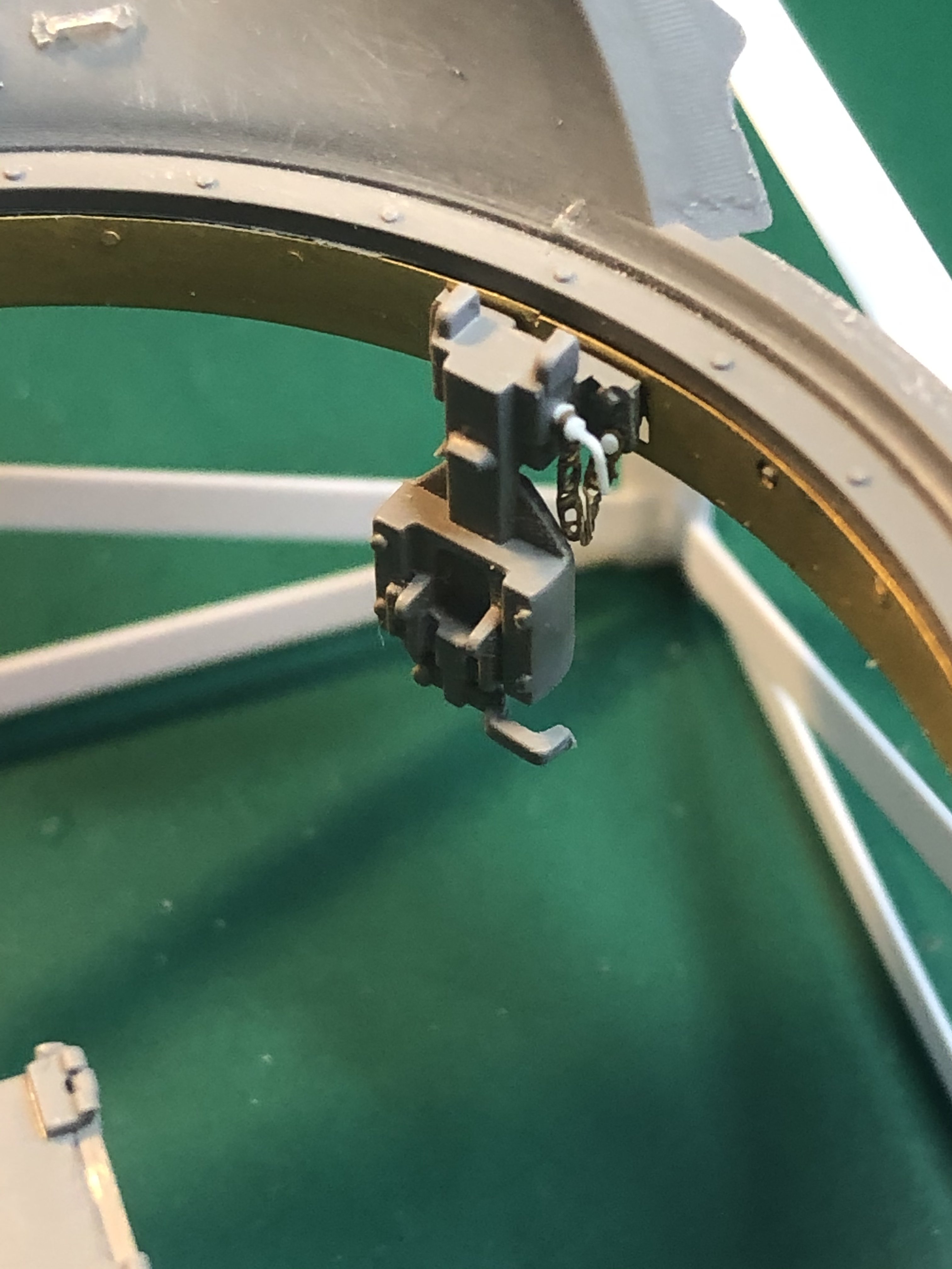
A few more things added to the turret interior. Finished the wiring in the back. Added the commanders seat and the loader seat. Add the pin and chain for the securing of the seat. Added attachment points for more cabling to the traverse mechanism and finally the latches on the ready ammo storage. There is also one on the other side. The one thing I am trying to figure out is the cabling from the manual firing pedal (pedal is located on the left corner of the turret floor and has a hole drilled on top) where in the bottom of the gun does it go to. I cannot find a good picture of it. I will keep searching. Tim


-
That is one large kit. Looking forward to how this comes together. Tim
-
Looking great! I like the subject. I want to try a 1/72 submarine one day. Keep the photos coming. Tim
-
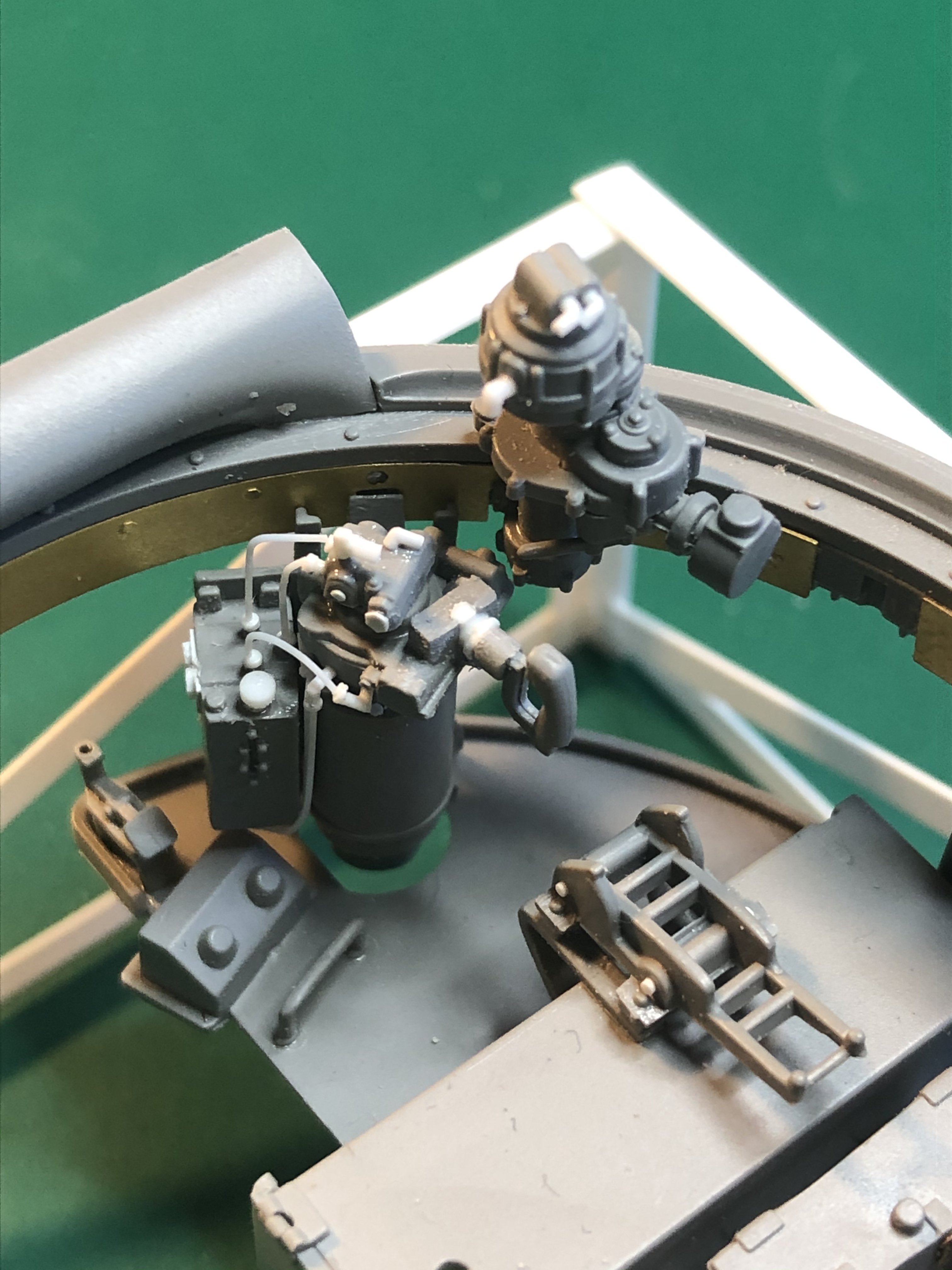
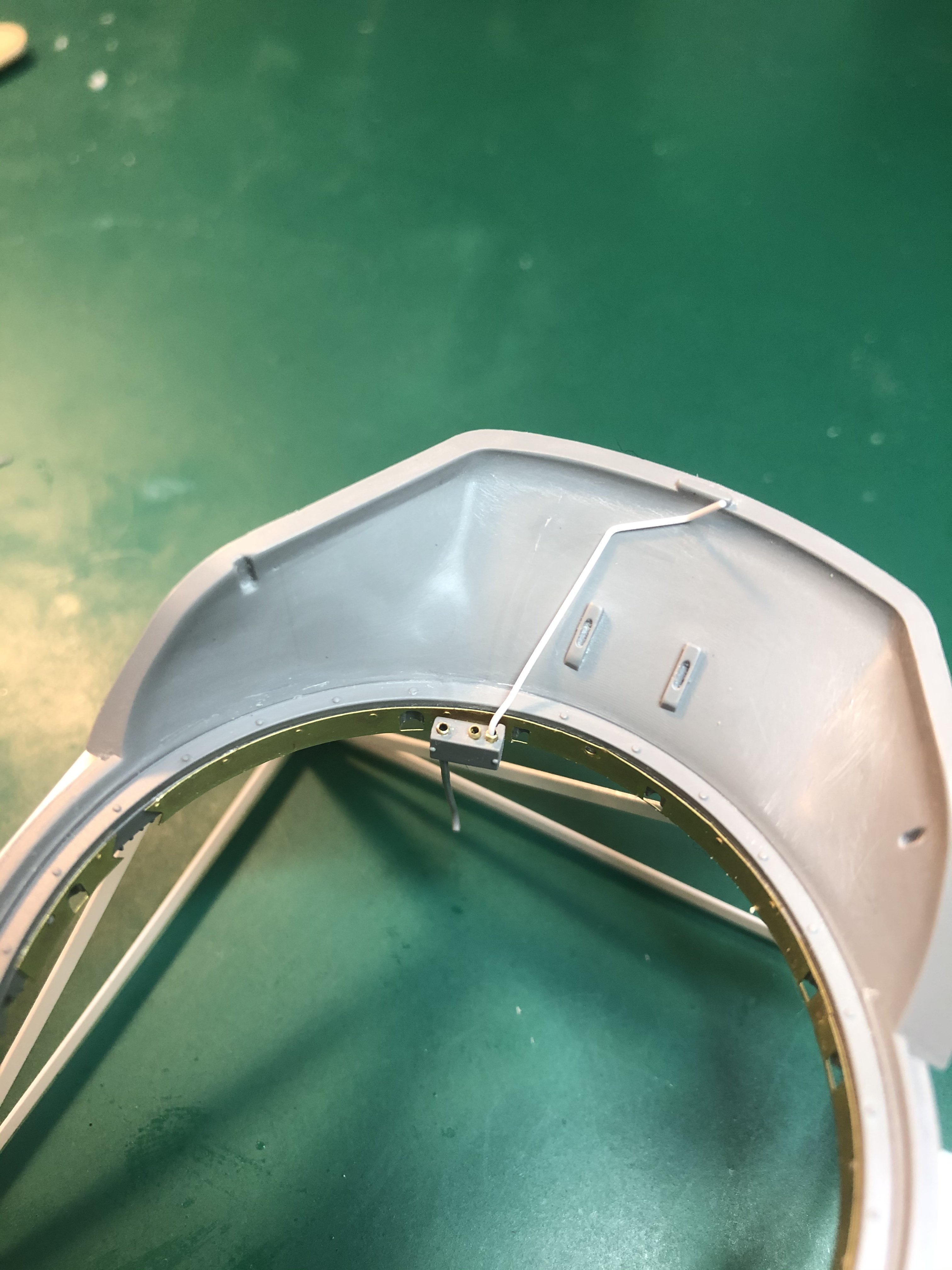
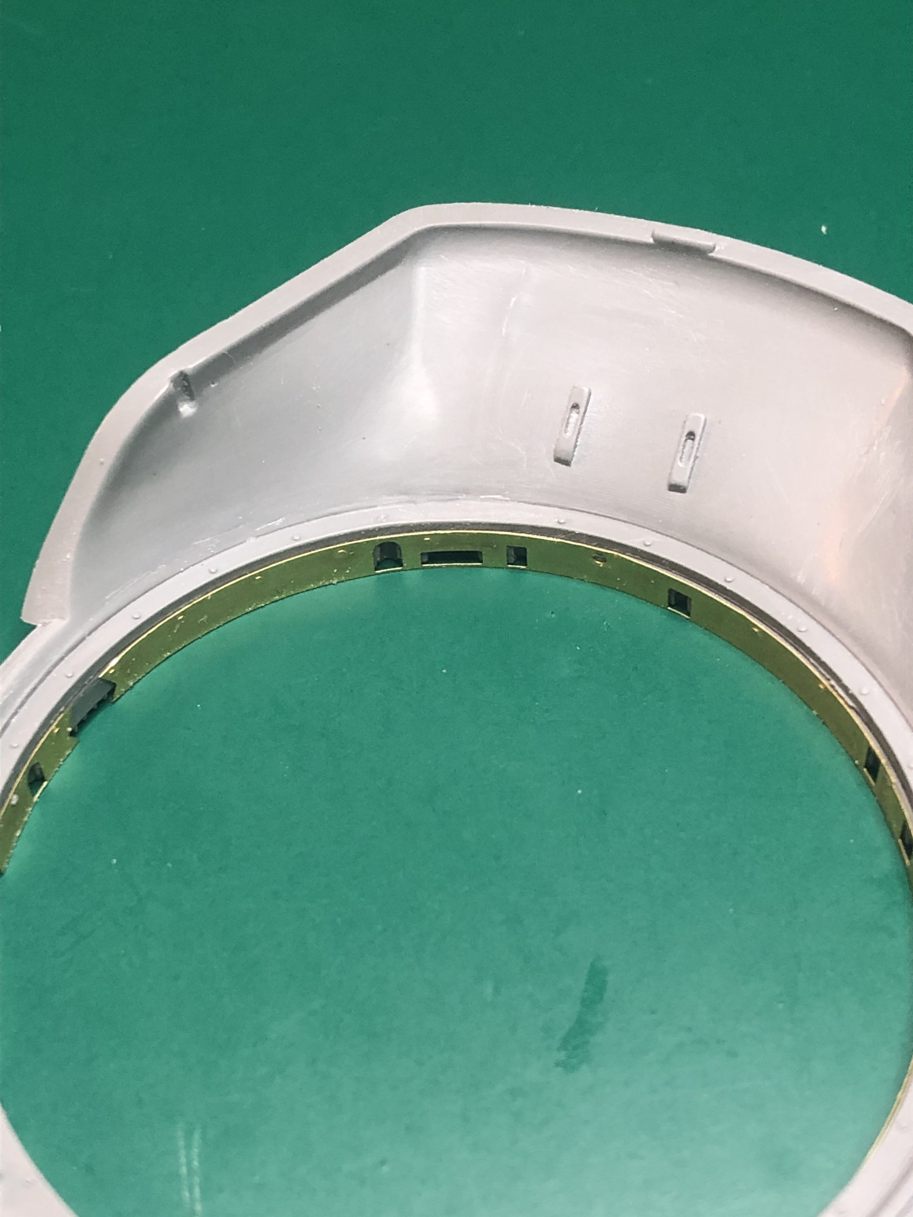
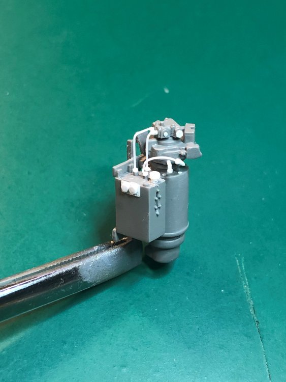
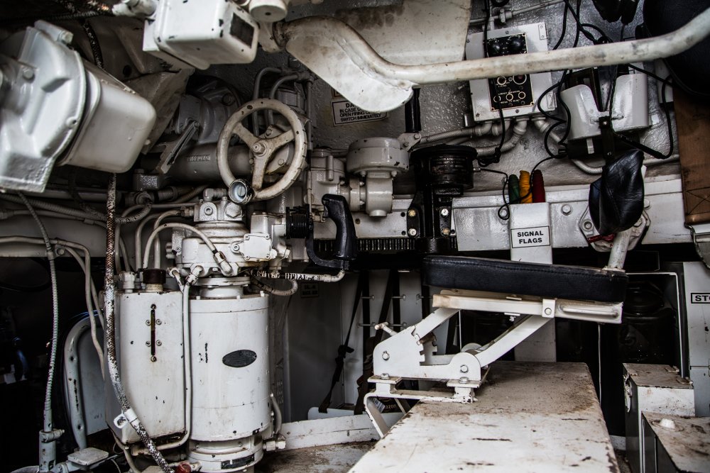
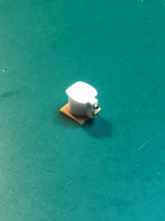
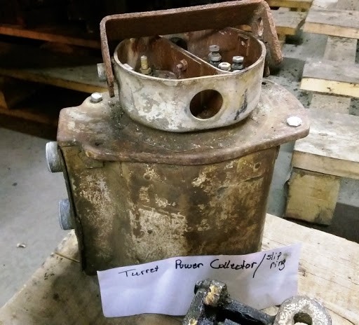
More work on the turret interior this week. Put the turret together. Adding some bolts to the seat base. Wiring to the radio terminal box with additional wiring to come. The bottom of the turret just did not look good as it can be removed to see the interior, and the bottom of the turret floor will be visible. Removed the molded in portion of the collector ring, added a scratch built ring, put a new floor for the bottom of the 6 round ammo storage, filled in the open portion below the gun firing box and added wiring to the new collector ring. The actual photo of the collector ring box and attached wiring shows how the wiring is connected. Even though this is the interior of an M26 this type of collector ring was also used in the M4A3. That is it for now. Tim

-
1:32nd scale Fokker D.II
Axeman replied to sandbagger's topic in LSM 1/35 and Larger Work In Progress
The painting is amazing. The prop is just stunning. Great work! Tim -
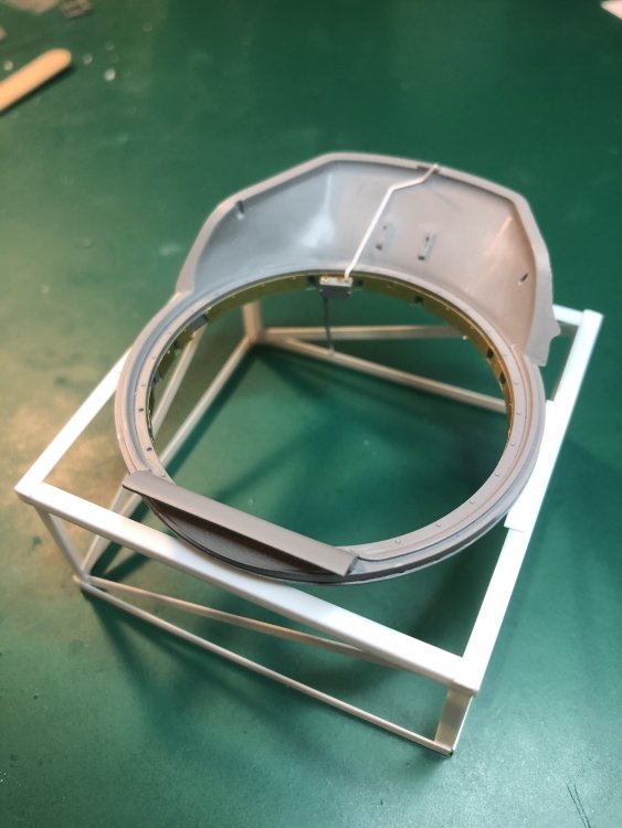
Small update. Created a stand for the turret so as I attach the basket it will not roll all over. Also started the wiring. Tim
-
PCM Focke Wulf FW 190 A-1/A-2/A-3
Axeman replied to GazzaS's topic in LSM 1/35 and Larger Work In Progress
Love the painting. Outstanding. Tim -
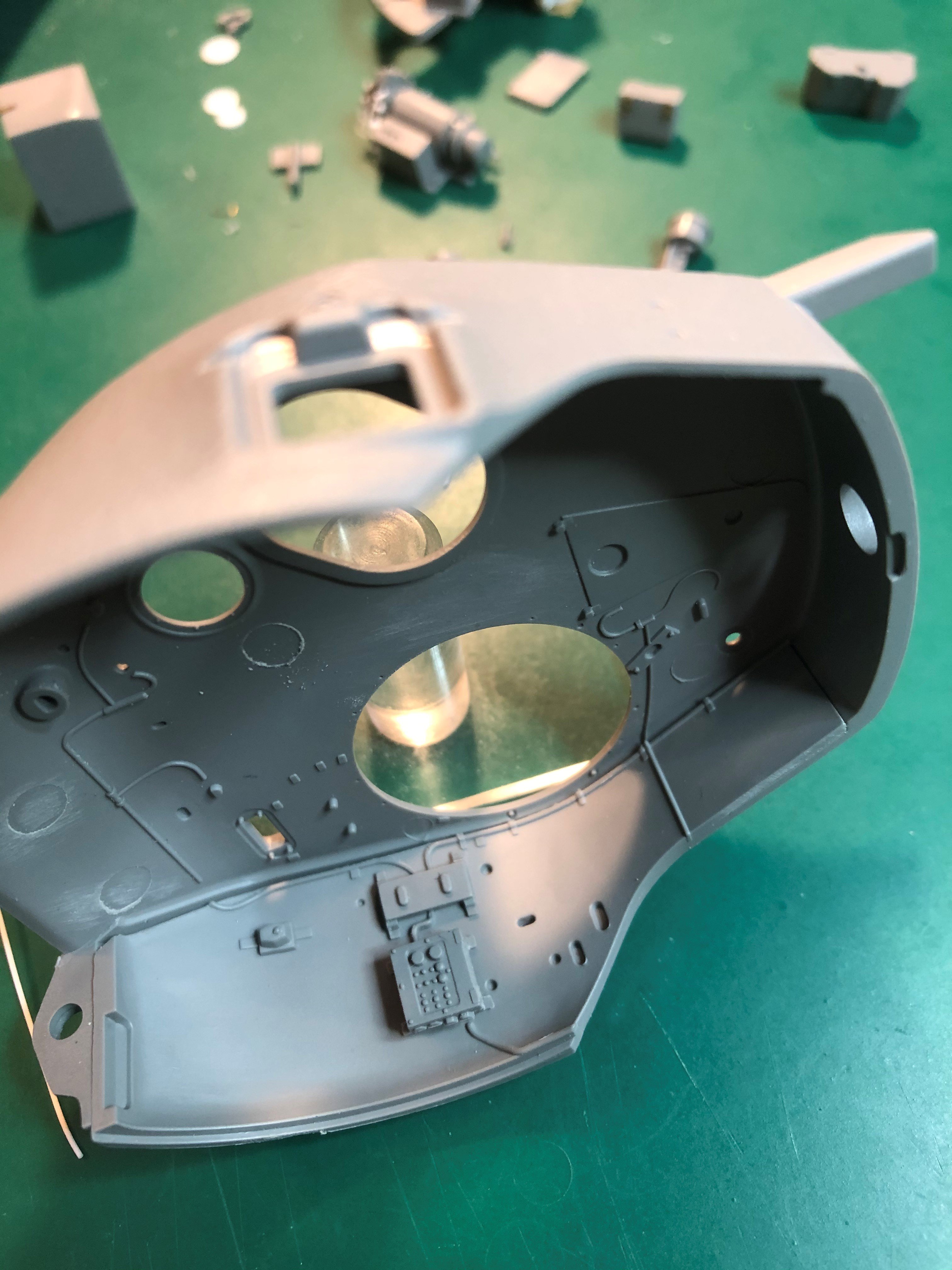
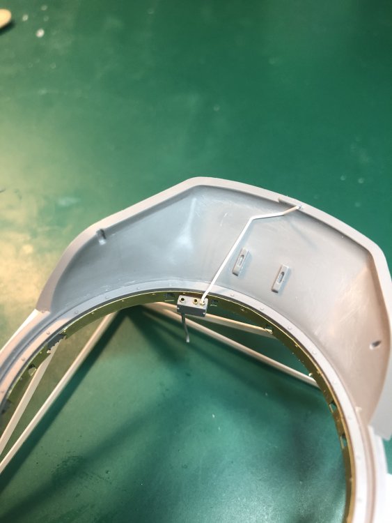
On the topic of cabling. I made the decision to remove the molded on cabling on the back of the turret that runs up to the radio and to the commanders area. Hopefully it will be wired up by this weekend.
-
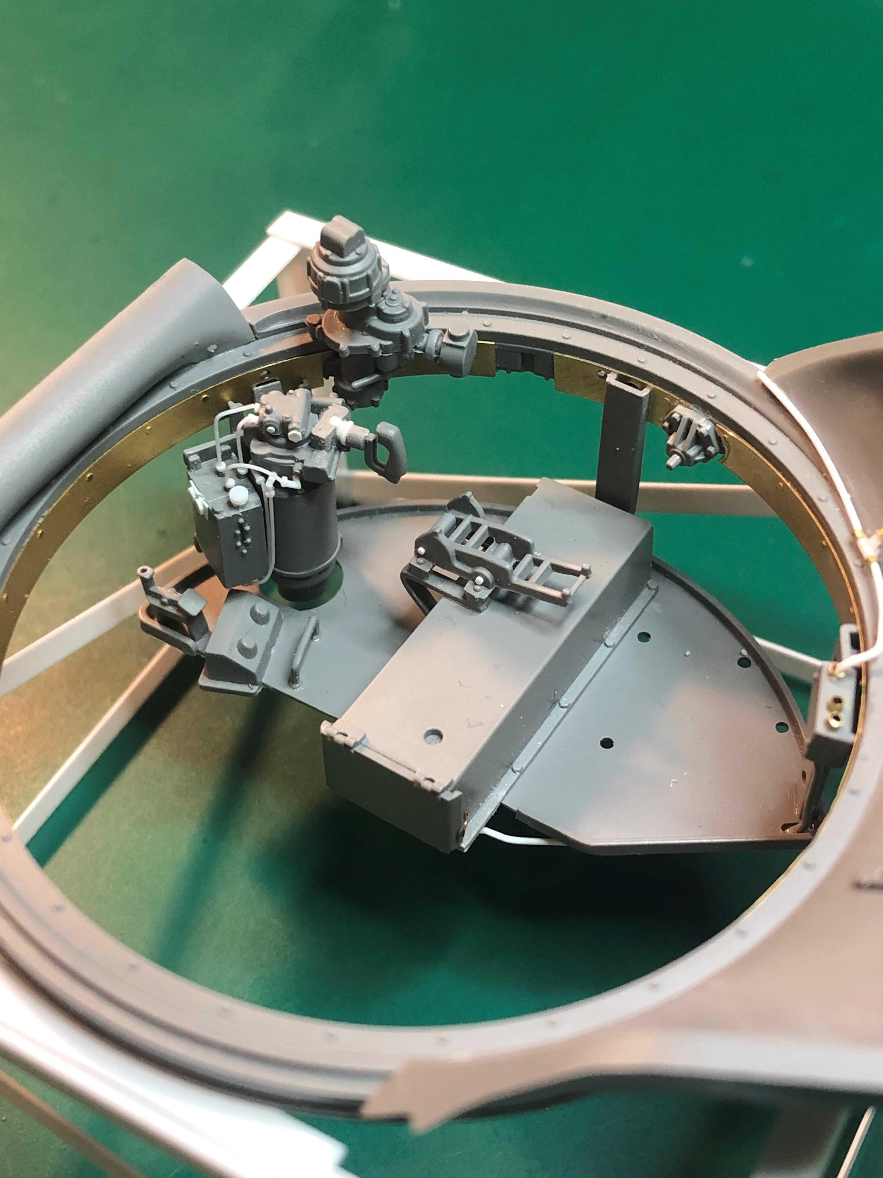
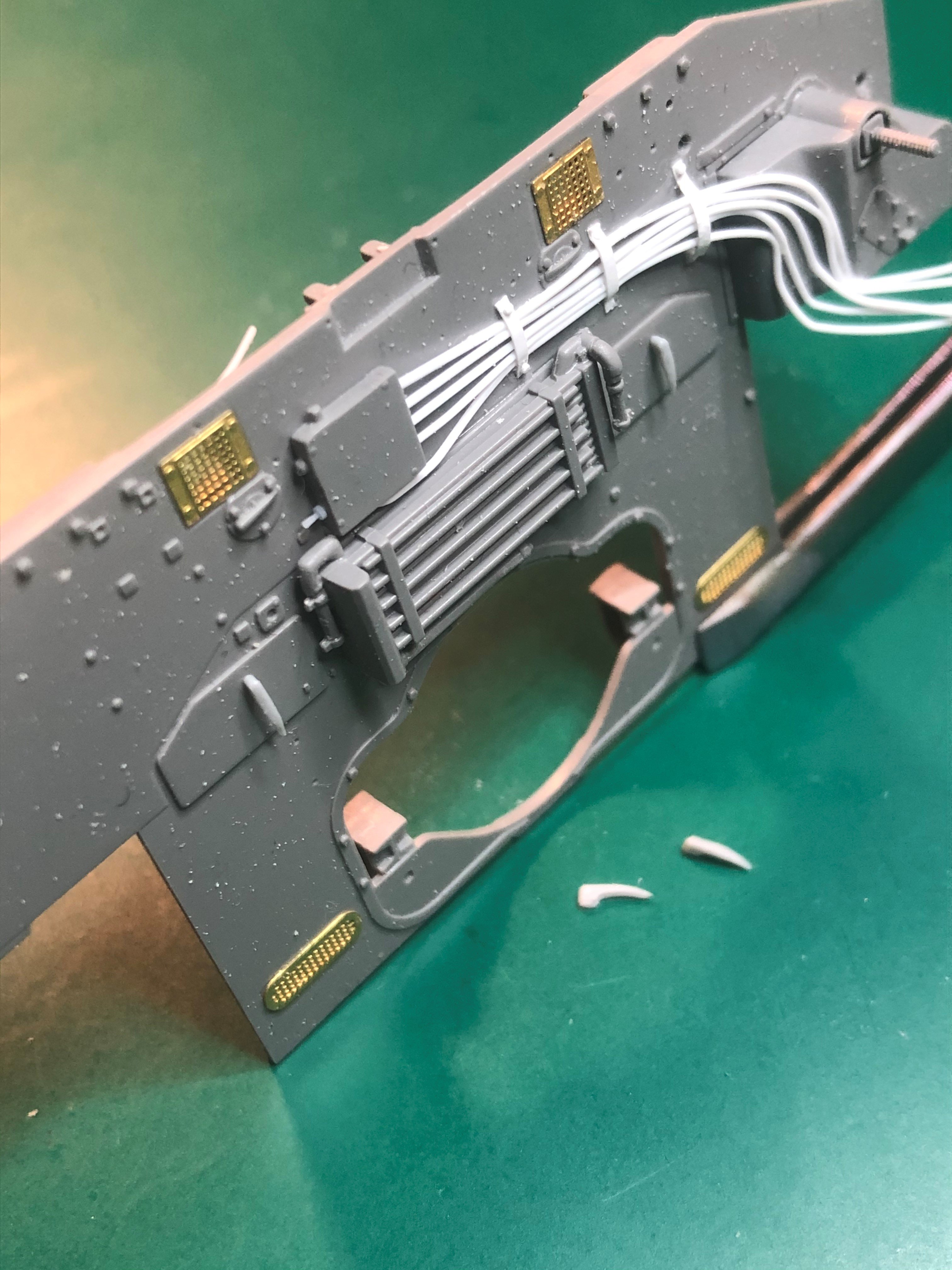
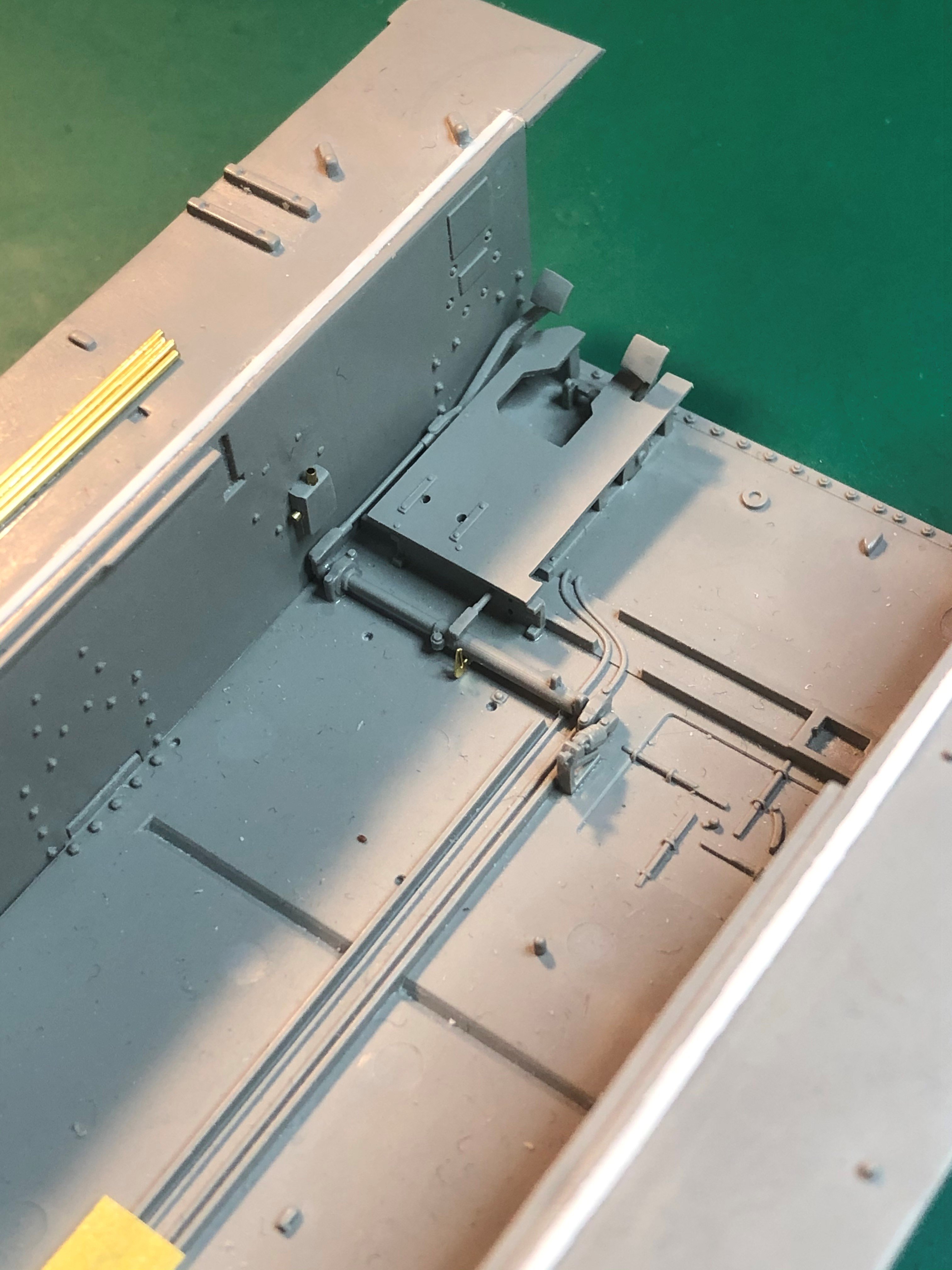
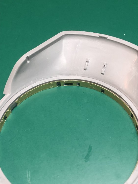
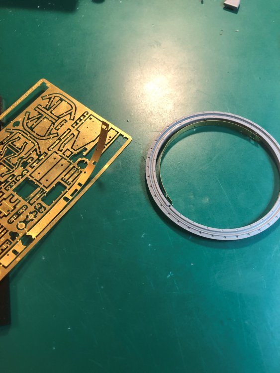
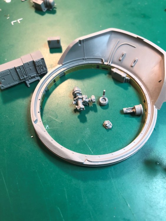
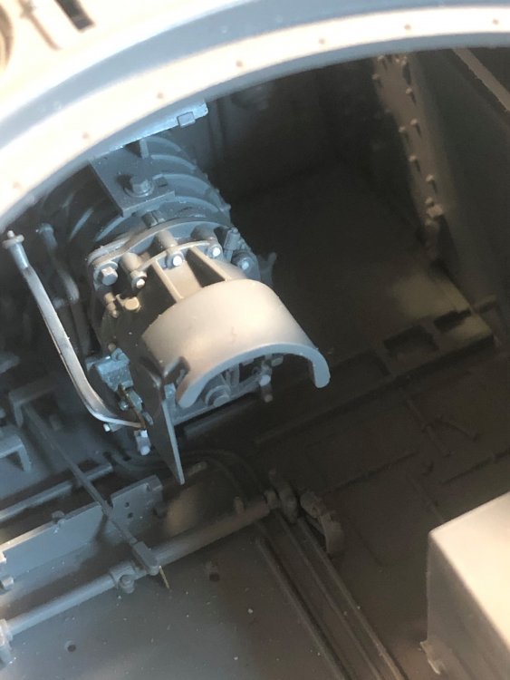
I realized that to find out where I need to position the collector ring box I need to find out how far down the turret "basket" drops down. So I started to work on the turret basket and it components. First I started on the latches on some of the storage boxes on the floor of the basket and the storage on either side of the radio box. The photo etch latches, are not exactly correct, but are good enough. Using a 3D printer for them would be best but I do not have one of those. So, this will have to do. Looking at the one box with a photo etch latch and the kit molded in latch. Next I worked on some adding the photo etch on the inside of the turret ring. When cutting off the photo etch, the photo etch formed the shape needed to attach inside the ring. You can see the one being cut of the fret and the ones inside the turret ring. I have never seen that before. Then some work on the traversing items attached to the turret ring and also the traversing mechanism that is attached to the frame of the turret "basket". The additional detail makes a difference and there is still more to add. Included a photo of the actual traversing mechanism. The storage boxes on either side of the radio, have opening on the side and back. I know they will not be seen but I just needed to close them up. Did not feel right even though me and you guys will be the only ones that know. The molded in wiring that leads behind the radio box, I am trying to determine if I want to keep it or remove it and add my own. The wire on the wall of the turret is much better and I will probably keep that but add more. While building I keep thinking of when to paint. How much do I put together and then paint or paint and then glue it. The struggle continues. So far no paint but get closer each day. That is it for now. Tim

-
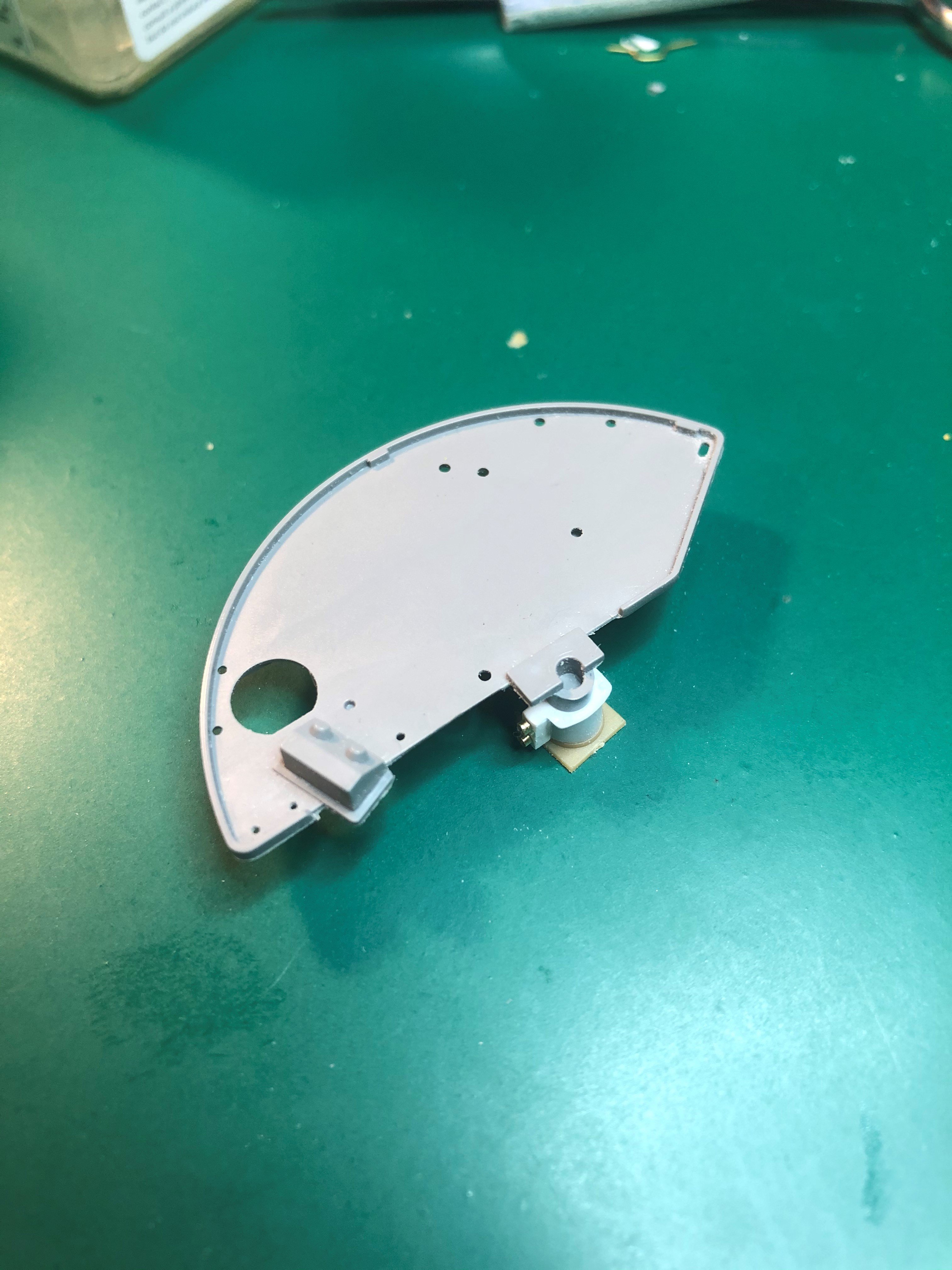
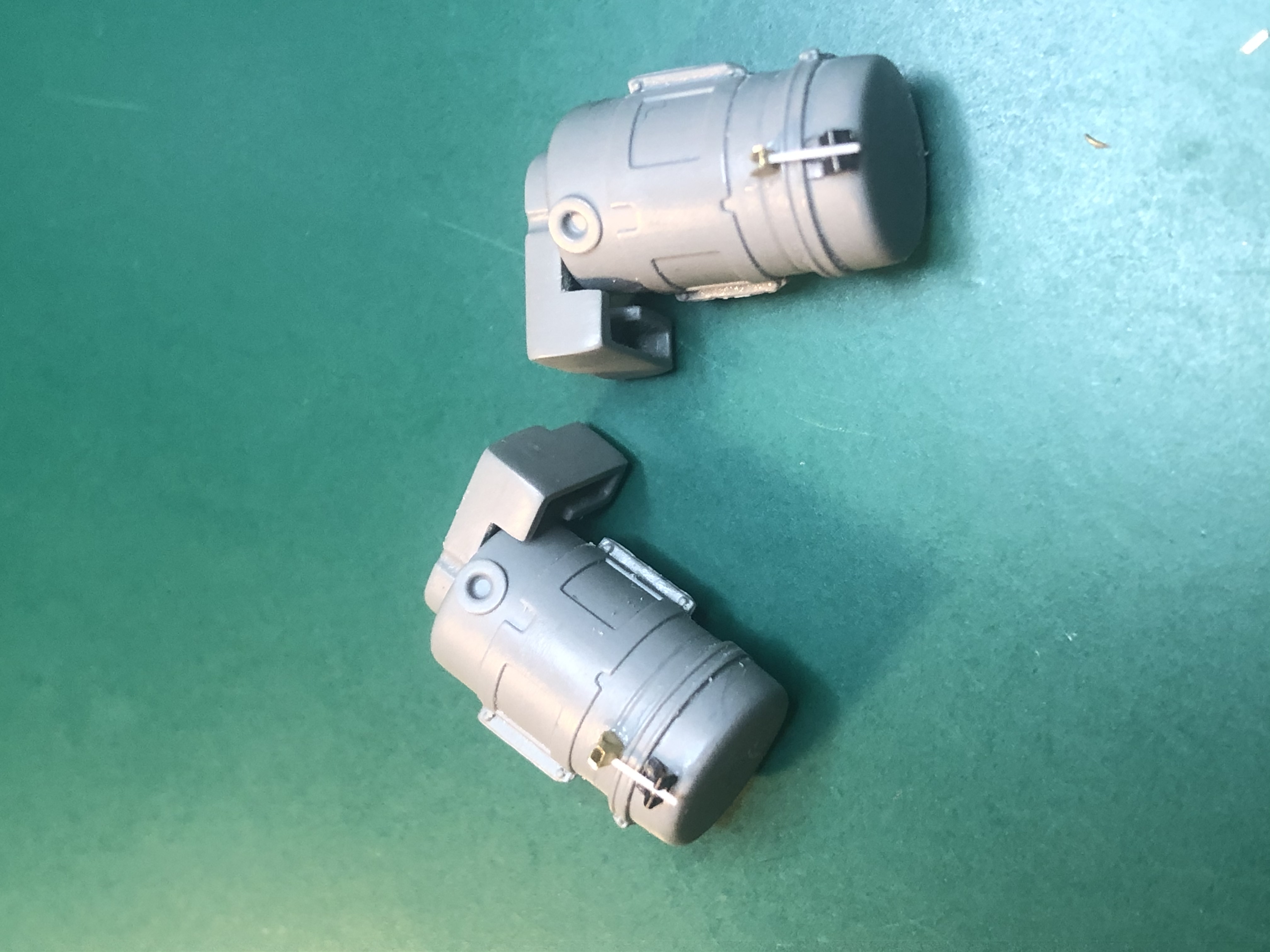
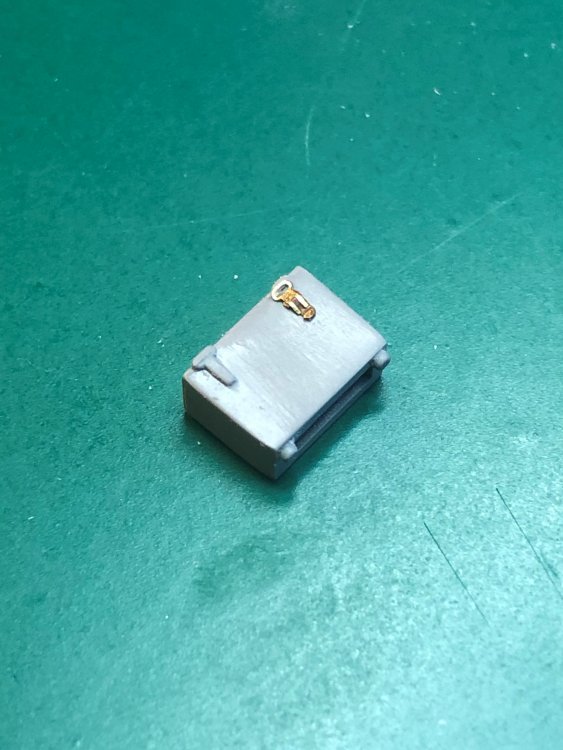
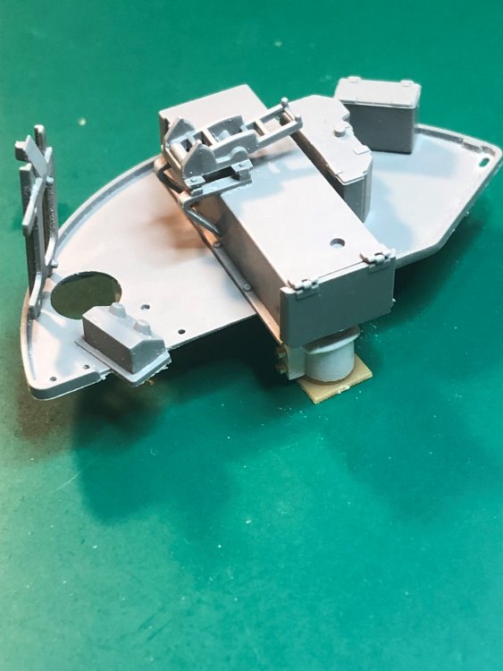
Well, I did not get as much done as I had hoped. Finished the collector ring box. In the photo of an actual collector ring the top portion, in the kit, is attached to the turret "basket" floor. I plan on leaving it attached in some form as I plan on simulating electrical lines to it. I might remove it, insert the U shaped attachment device and re-glue it back. To determine how far down the collector ring needs to sit I need to start to do work on the turret "basket" floor. Pictured is progress so far. Until next week. Tim

-
Thanks. Working on the collector ring.
-
Bent wing bird- Tamiya F4U-1A
Axeman replied to BlrwestSiR's topic in LSM 1/35 and Larger Work In Progress
Looking good so far. Great work. Tim -
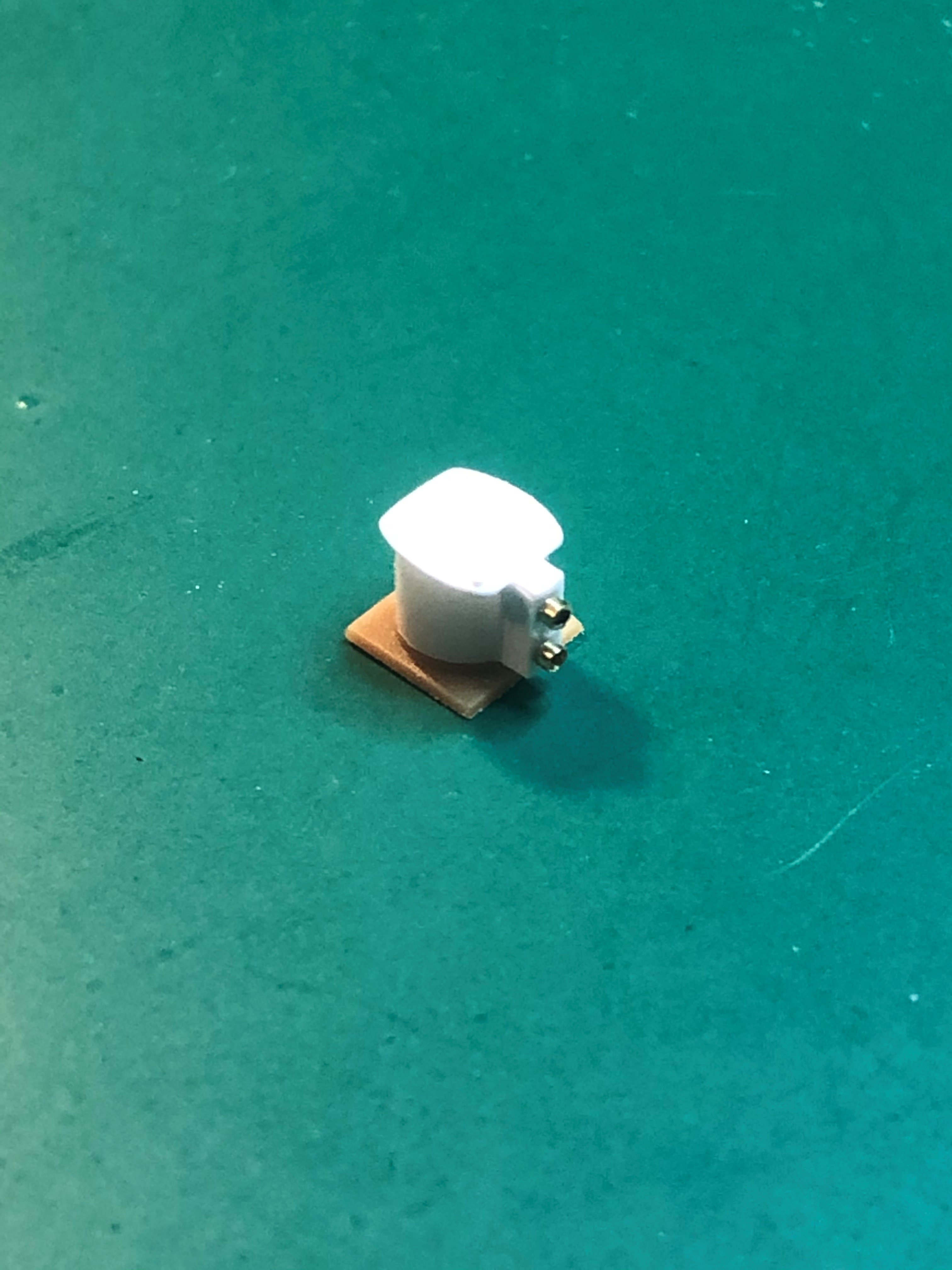
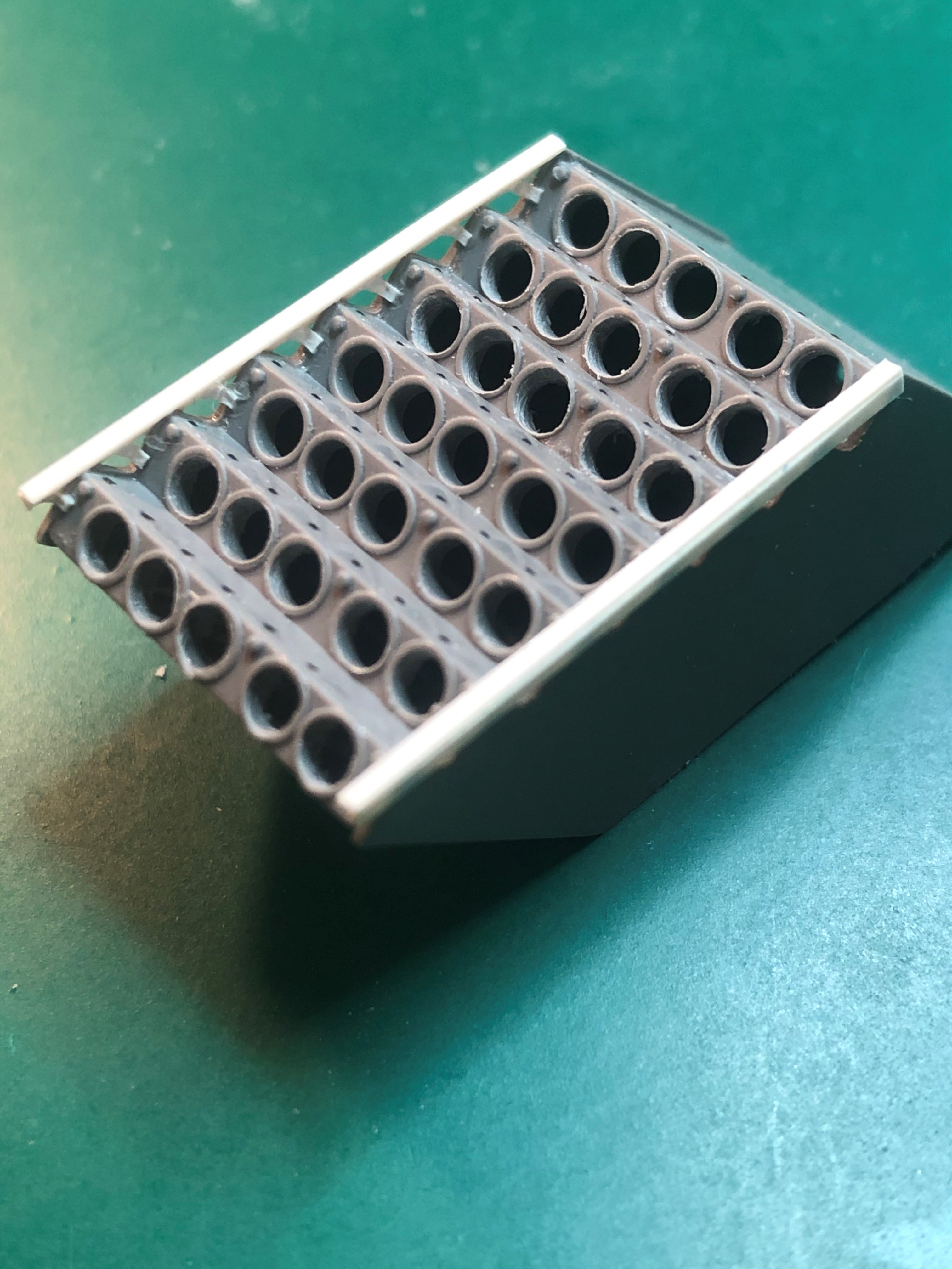
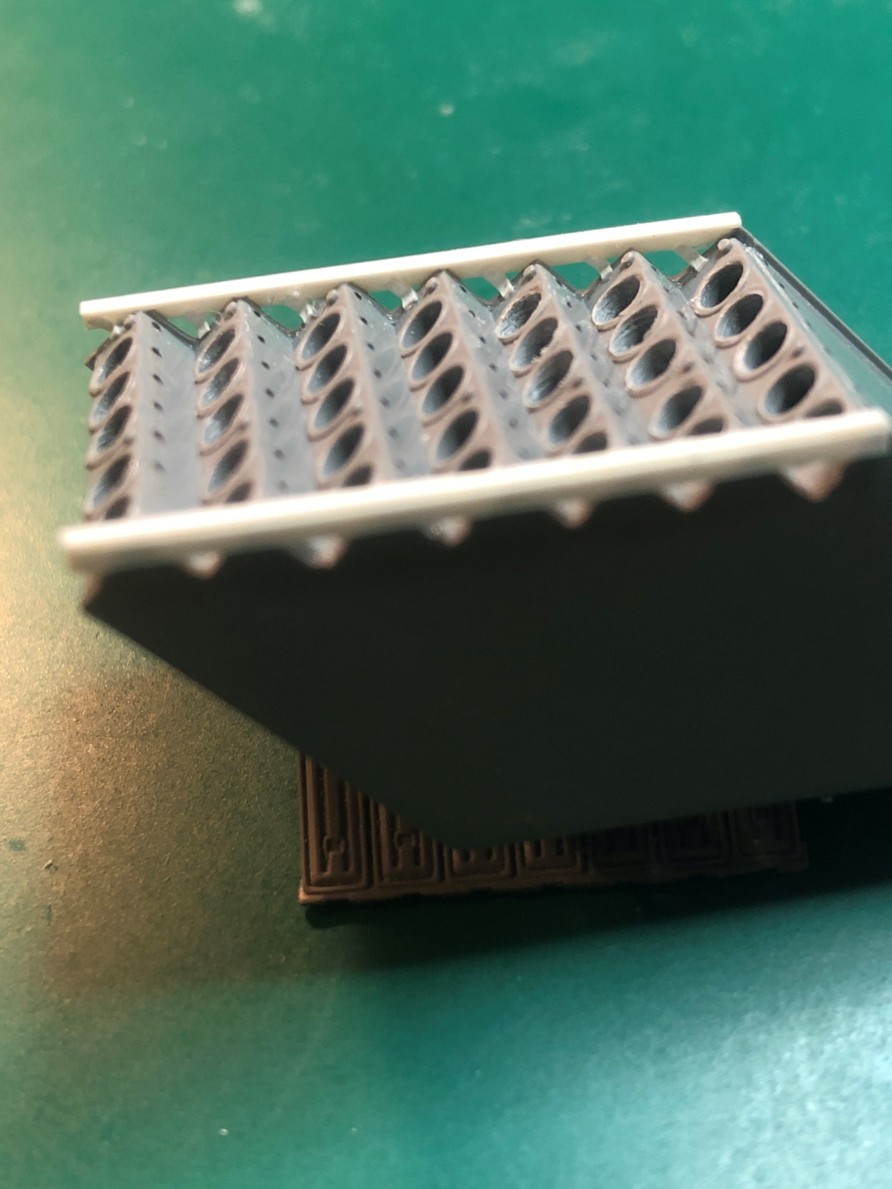
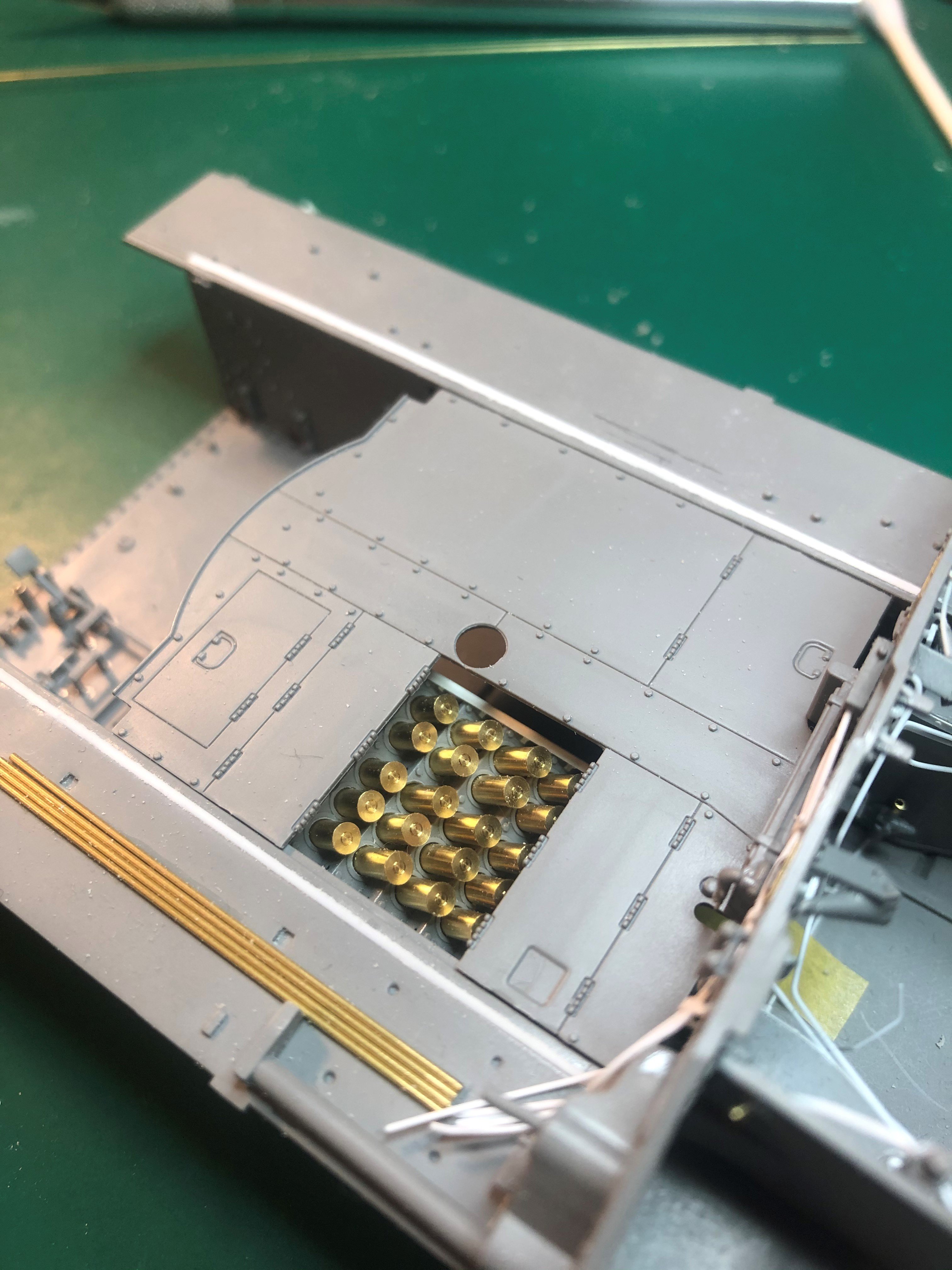
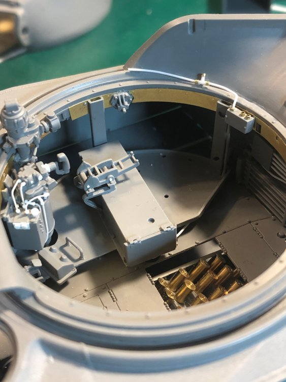
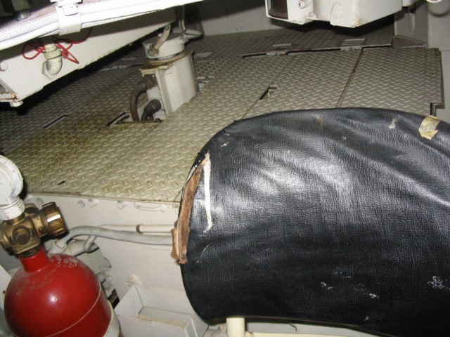
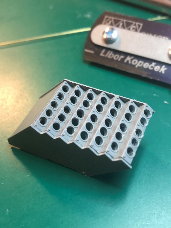
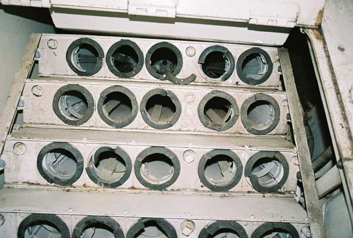
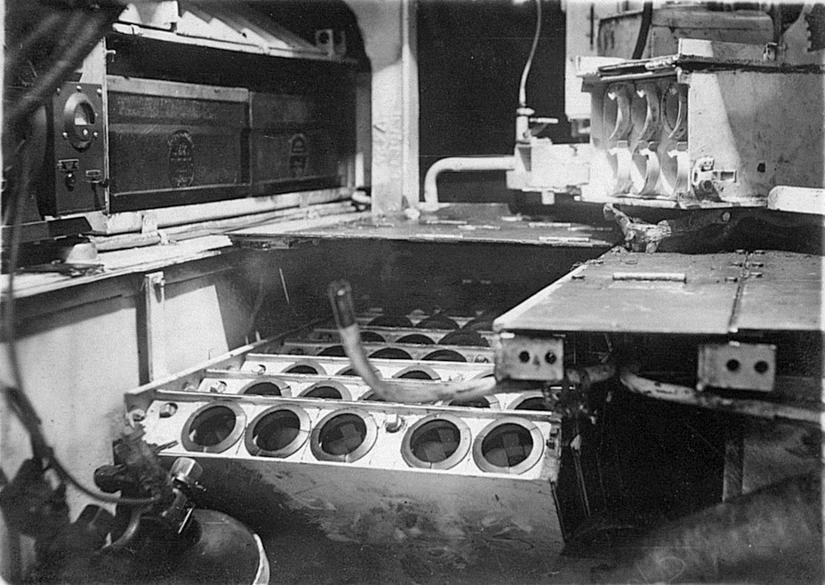
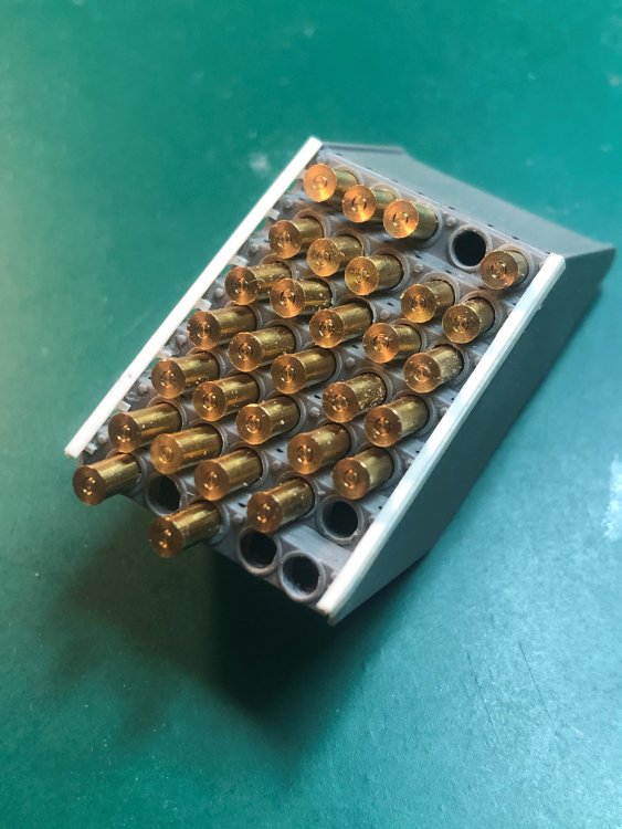
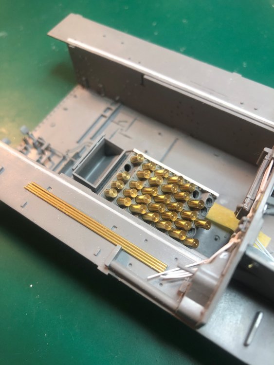
Worked on the main ammo storage. First, I drilled out all of the openings for the shells. The kit only has two rows of openings and the rest are the tops of shells glued to the top of the opening. Next, I removed a portion of the sides creating a zig zag shape. Once that was removed I added an L-shaped bar on the top and and braces from each of the "ammo storage boxes". The actual storage units you could see through between the bar and the boxes. In the color photo of the actual storage, you can see the openings on the right. I will also make the collector ring which you can see between the floor plating and the ammo storage frame (bottom right of the picture). That is still to come. Next, I put the brass shells (ARV Club) in place. They are looking the part. However, if I enter this into one of the local IPMS competitions, to leave them brass is not allowed, it needs to be painted. Not sure what I will do with them. Until later. Tim


-
Great work! Love the scratch building. Tim
-
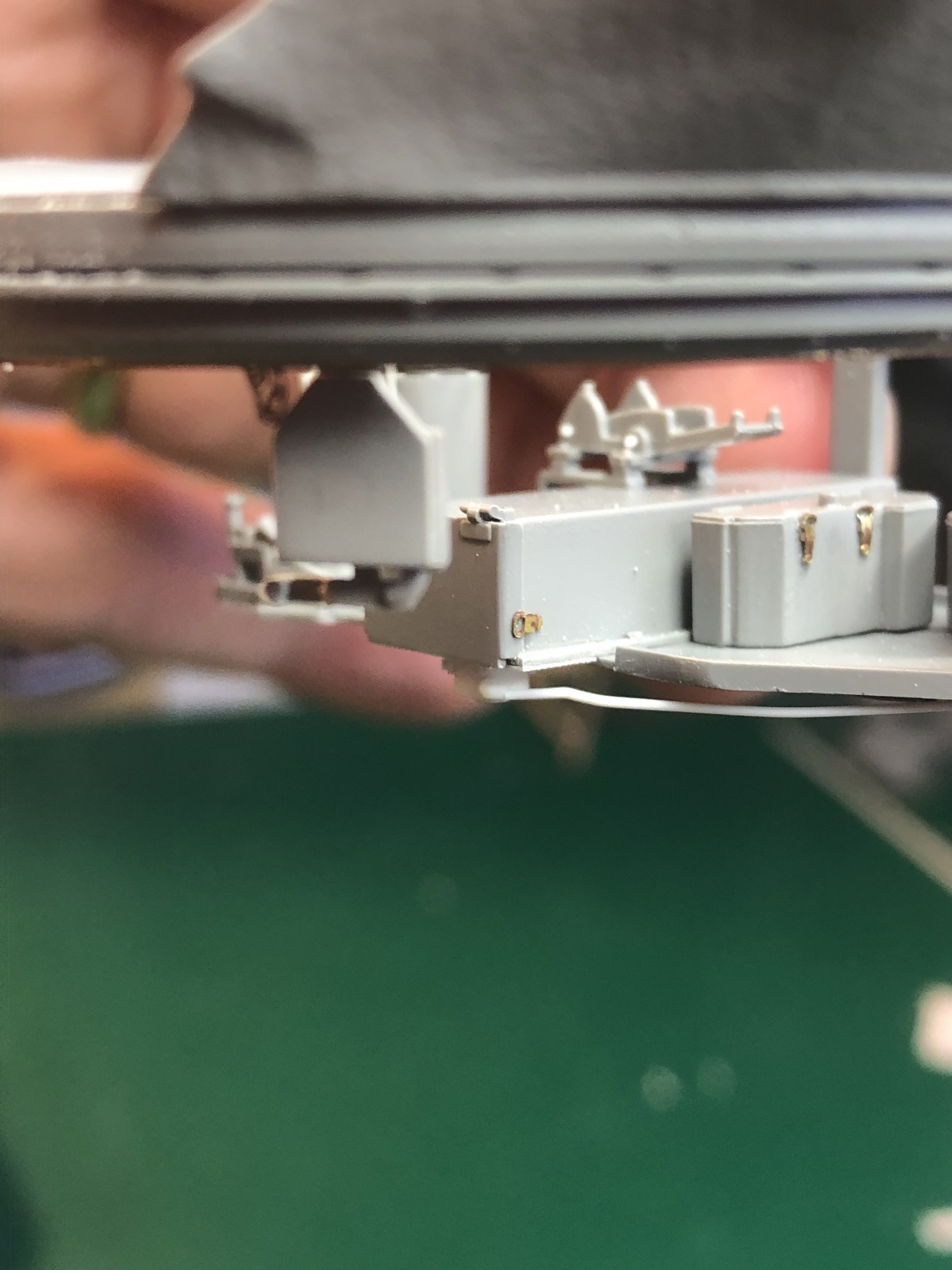
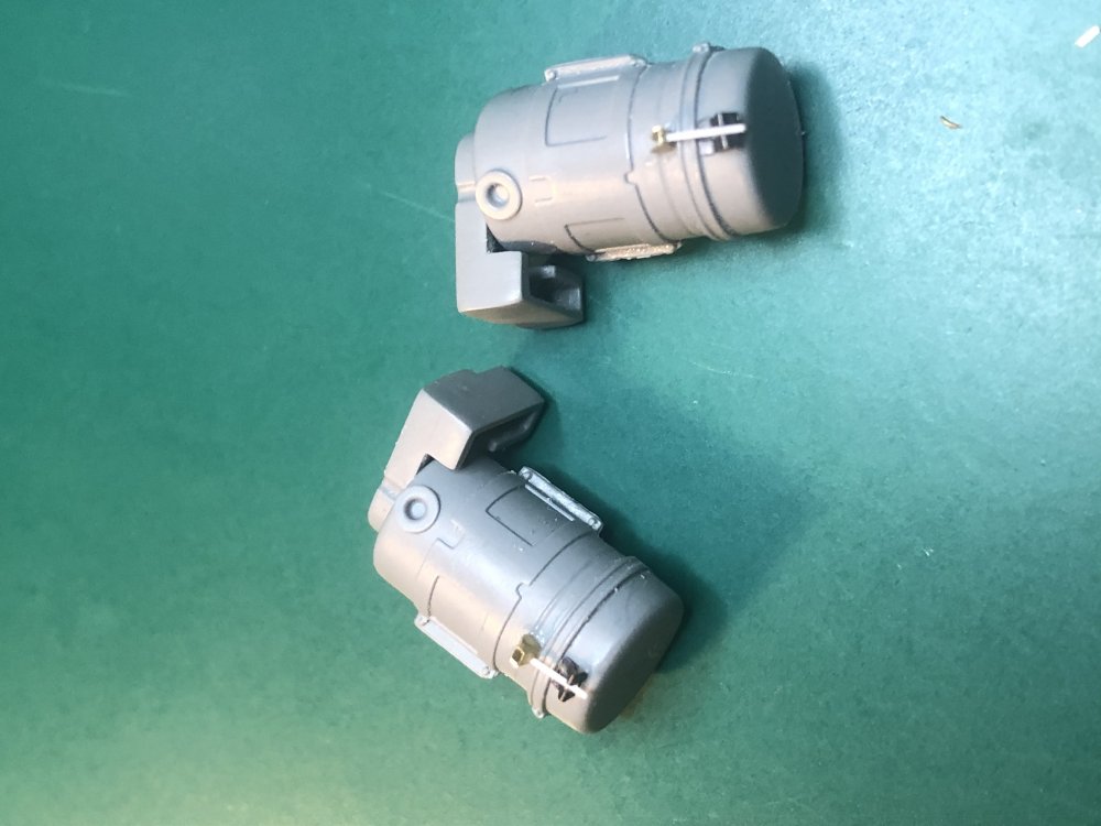
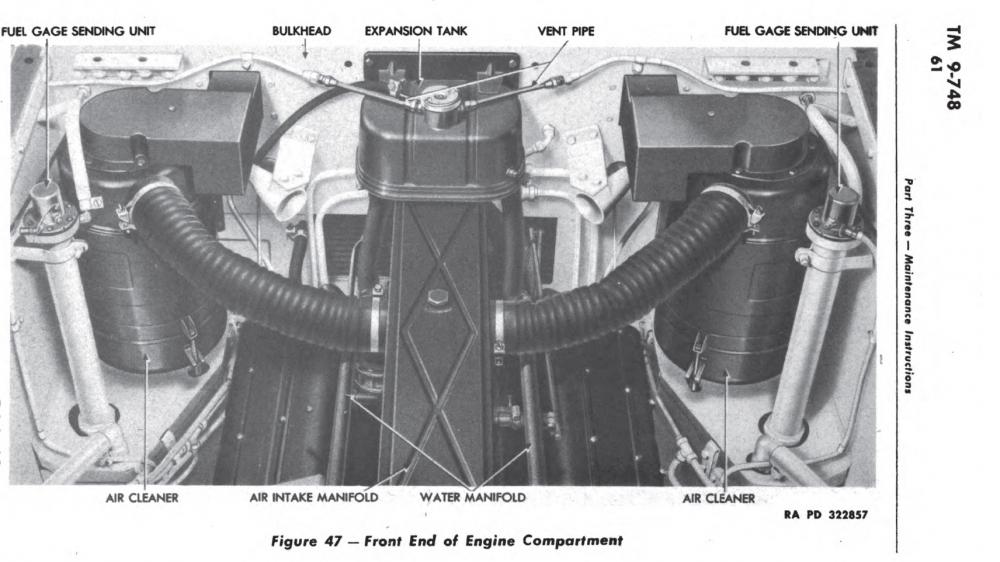
Thanks guys. Added some brackets/clamps (not sure it that is what they are called) to the air filters last night. You can see them in the Technical Manual photo. I believe the hold the filter in place. Working on the latches to the battery storages box. Tim
-
Looking forward to see how the Quinta instruments look.
-
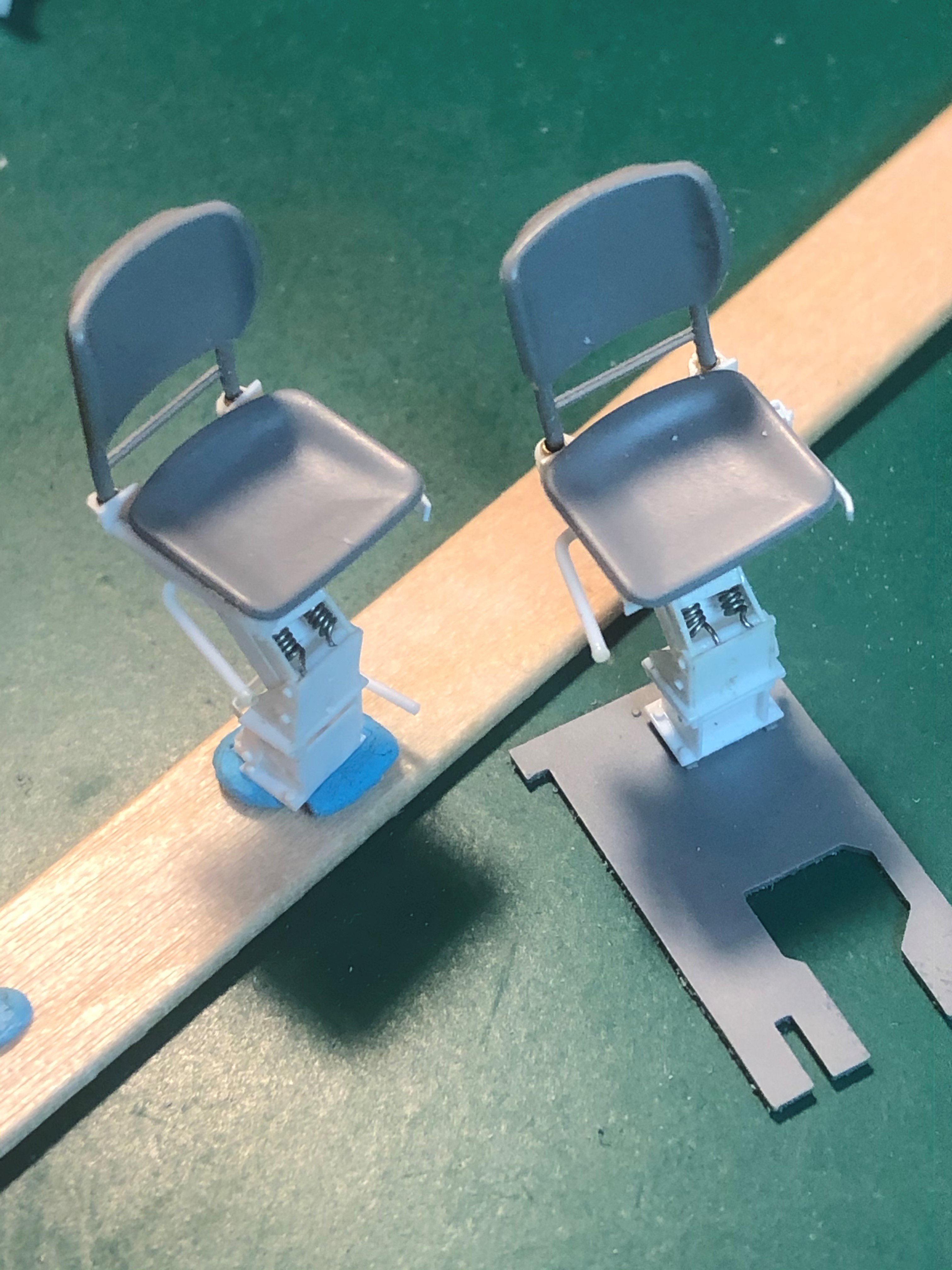
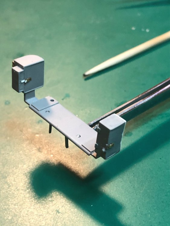
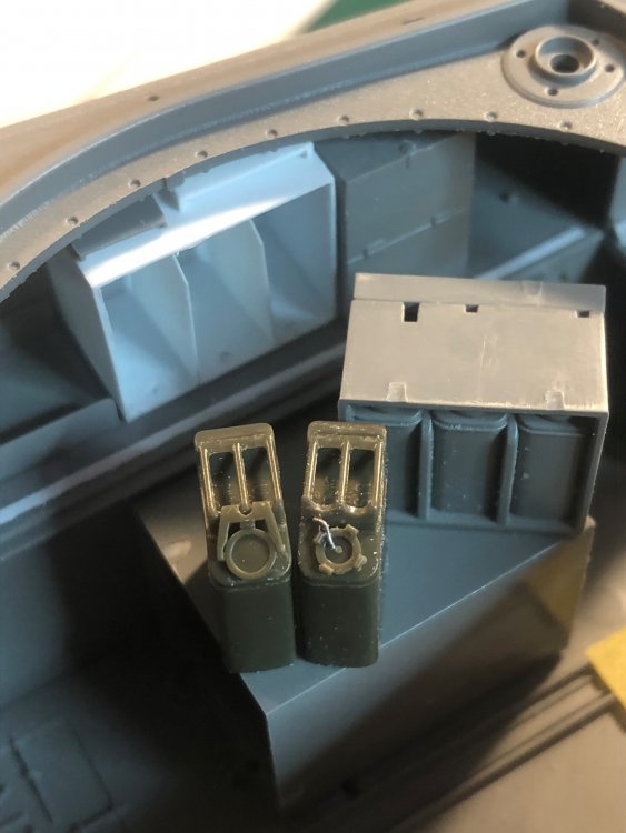
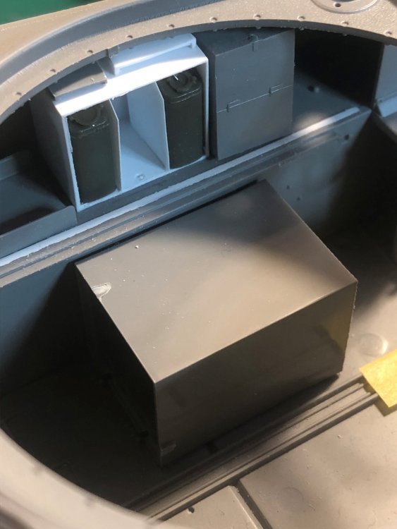
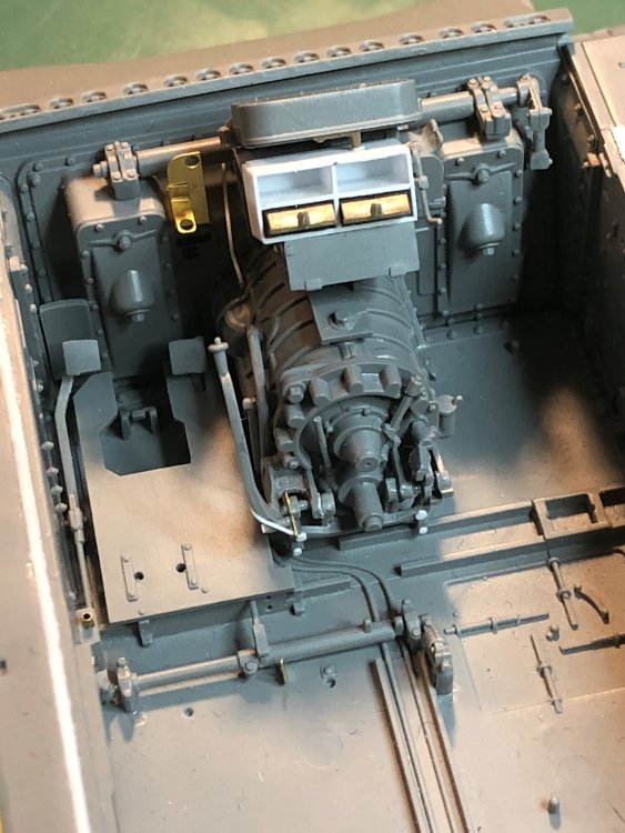
Did a little more work this weekend. Not as much as I would have liked. Finished building the Jerry Can storage. One of the pictures shows the kit storage which is the same height as the 1/35 jerry can. I wanted to show one spot open. Included nuts that would have held the unit in place. Second picture is the the jerry cans temporarily in place. Also glued the generator cover to the transmission and added bolts. Shortened the depth of the seats. They are ready for painting. Lastly, added the oil cooler and then the new handles to the air cleaner service opening doors and added the transfer switch to the terminal box. The switch is from Anyz and the handles are from Tiger Model Designs. Hopefully better progress this week. Tim


-
Great work on the Sherman.
-
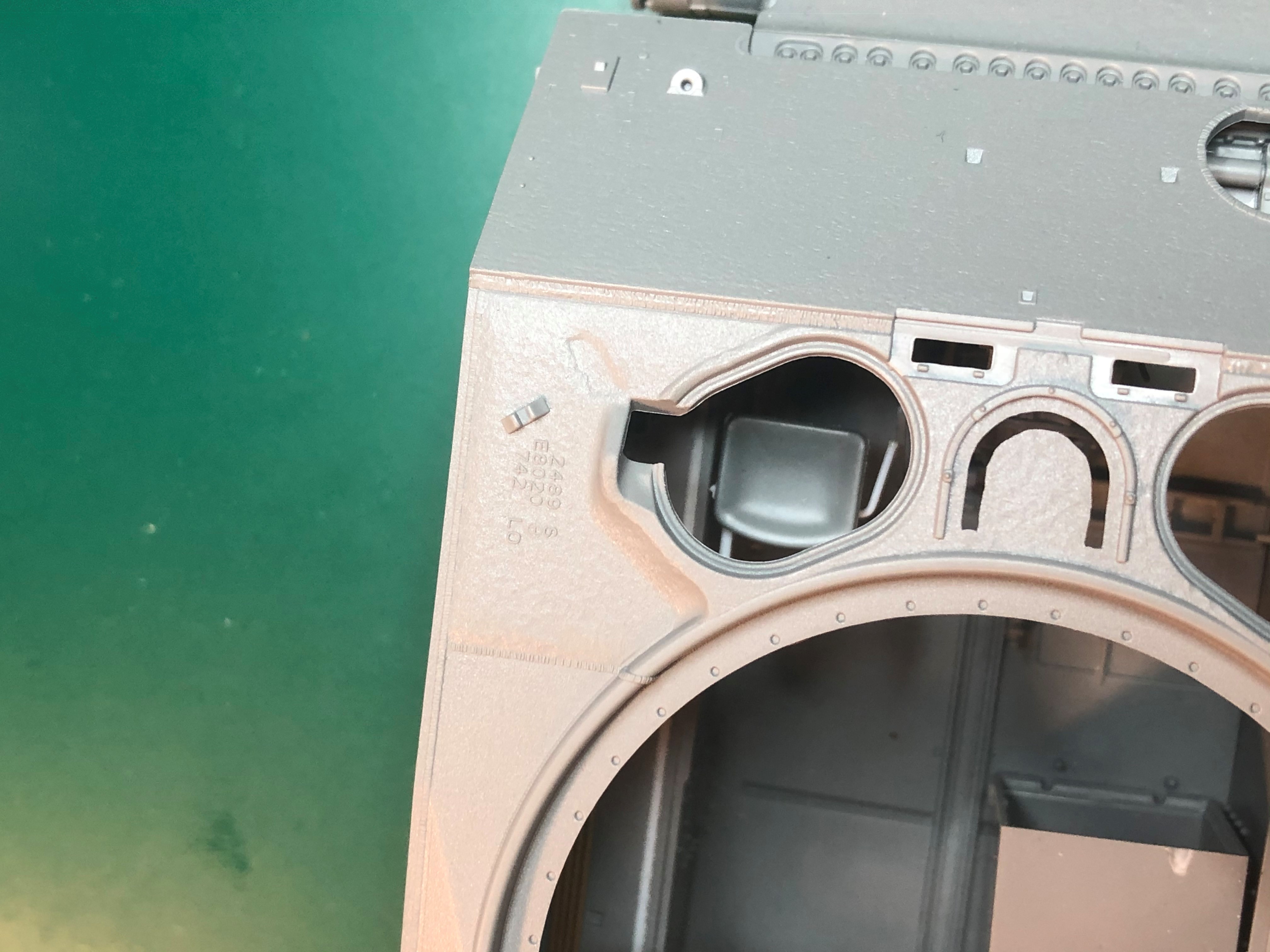
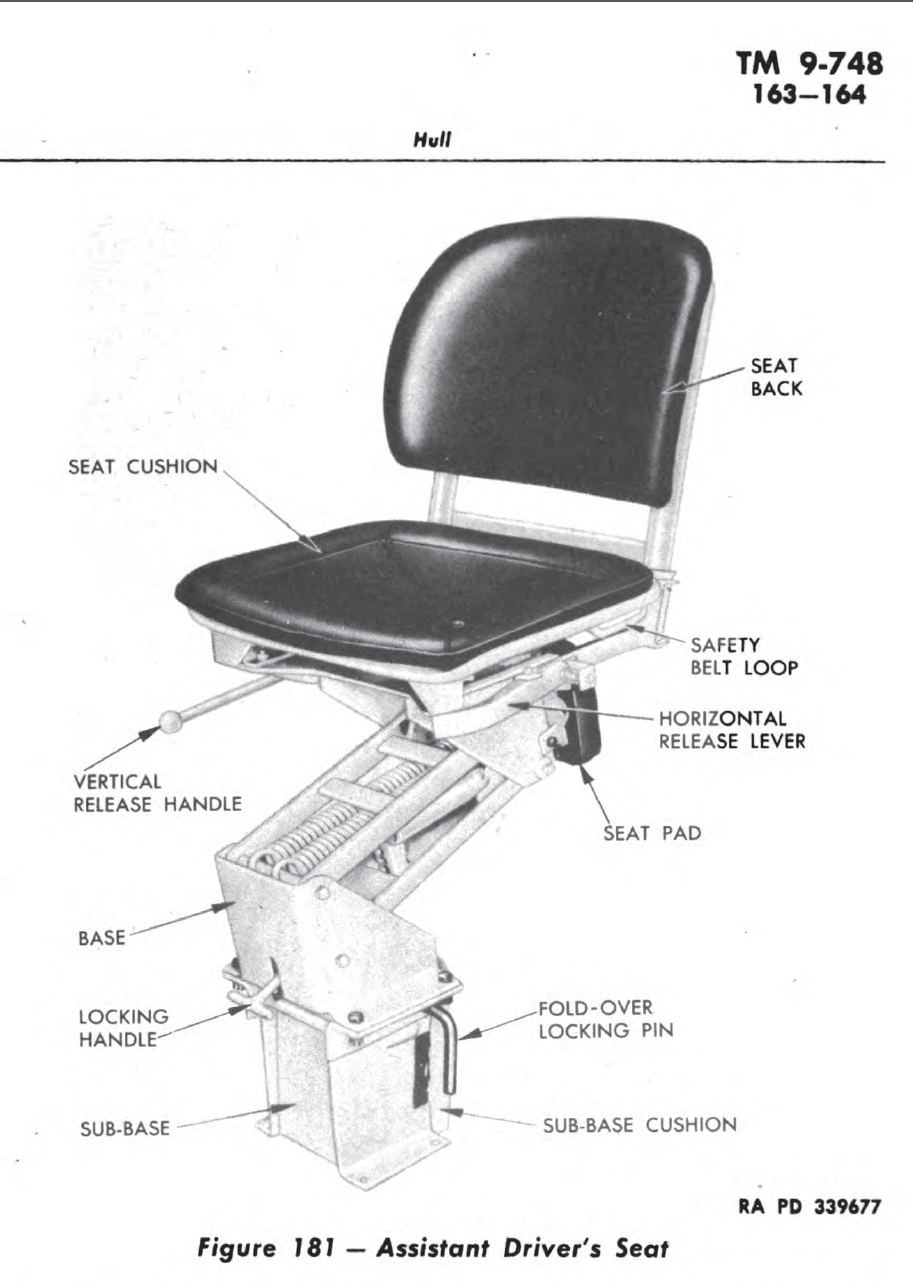
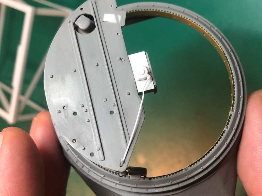
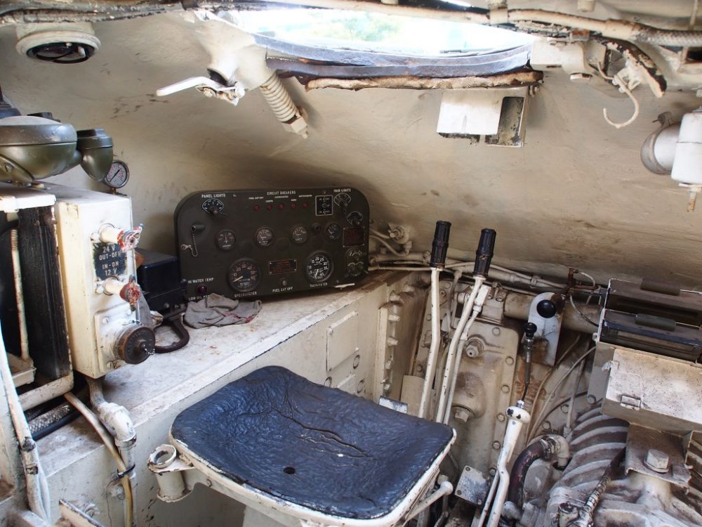
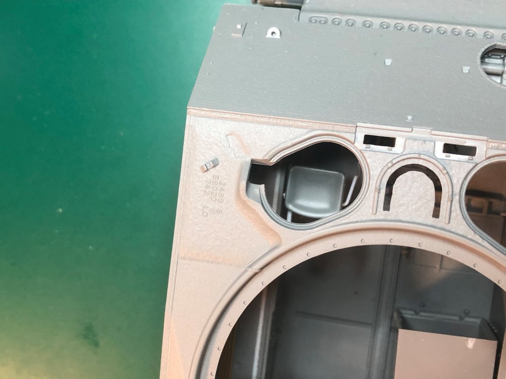
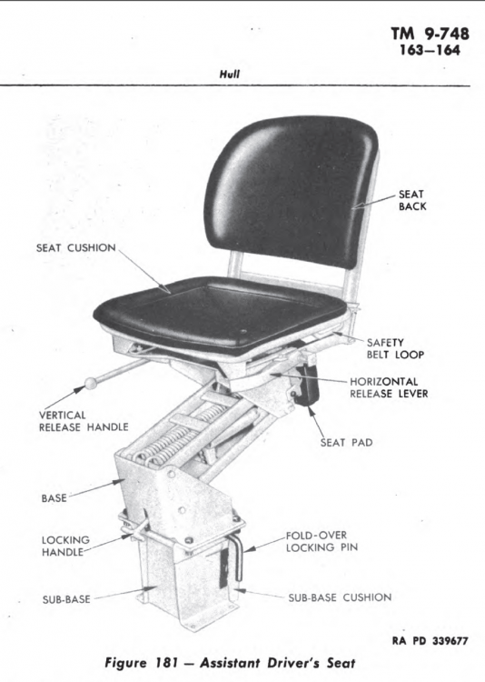
Good question about the seat. The seats were adjustable, being able to move up and down and backward and forward. I do have another picture were the driver and asst. driver seats are not parallel. In addition, the asst. drivers seat can fold forward for better access to the escape hatch. Not sure if the drivers seat does that. That got me thinking and I needed to double check were my seat was placed. I just checked and I think the seat was leaning backwards (as it was only held down with blue tack) and the plate underneath slid backwards. I adjusted both of those items and it looks correctly positioned compared to the actual photo. The front edge of the seat is even with the generator regulator. Looking down through the open hatch and the seat is underneath. The height of the seat looks good also as the seat is around the height of the sponson which is the same as the photo. Glad I checked and made sure it was ok. Great spotting. Tim

-
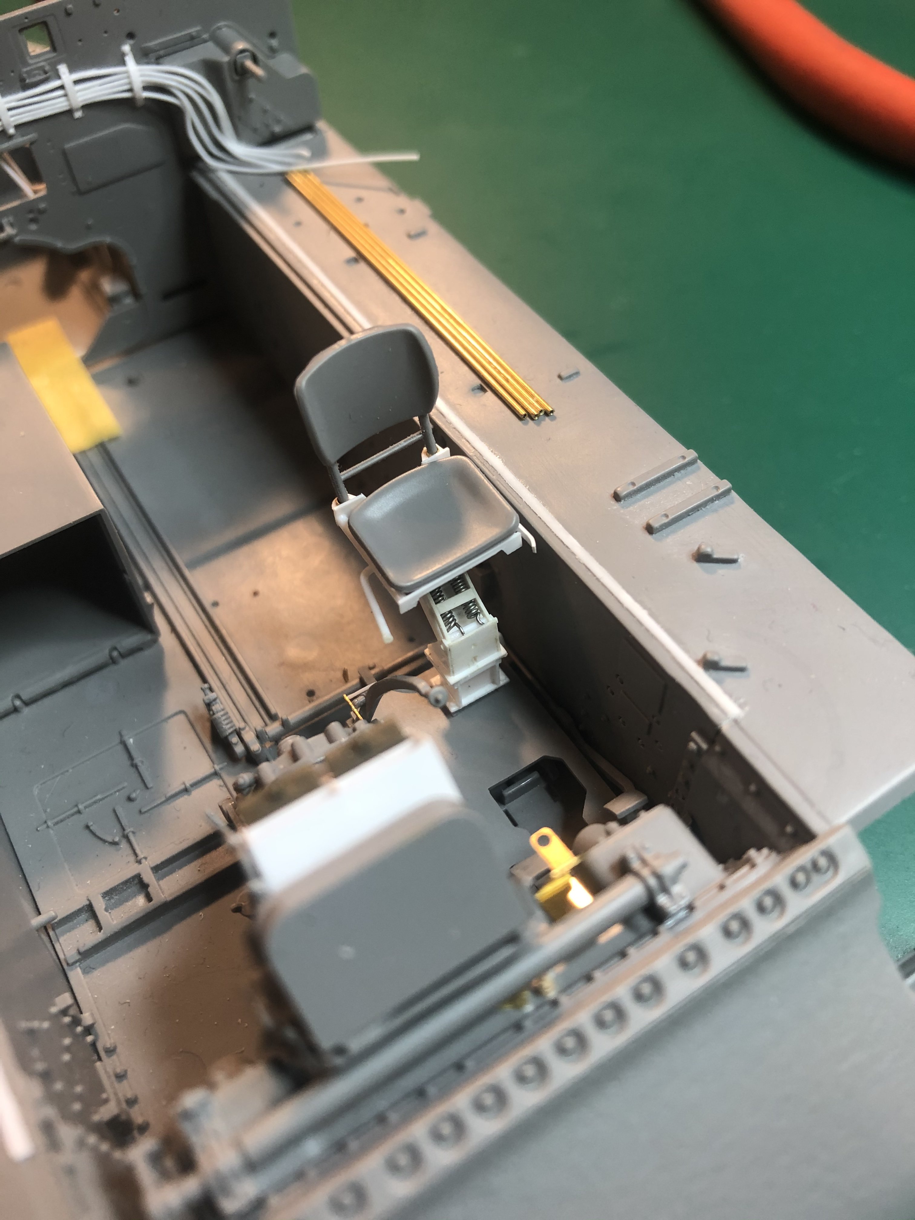
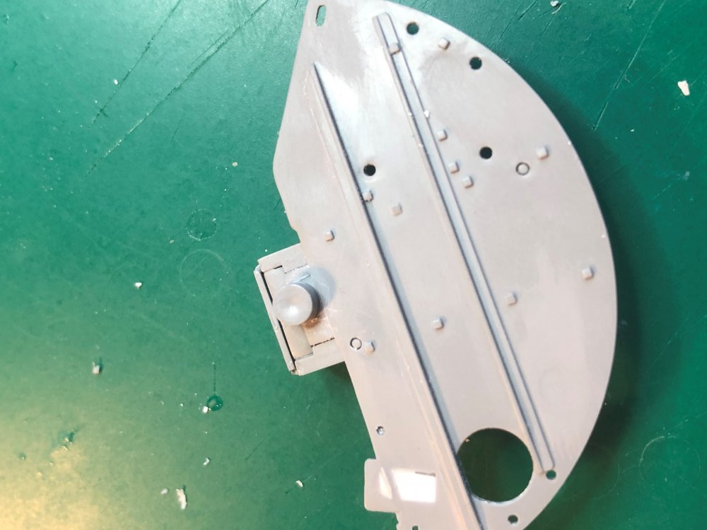
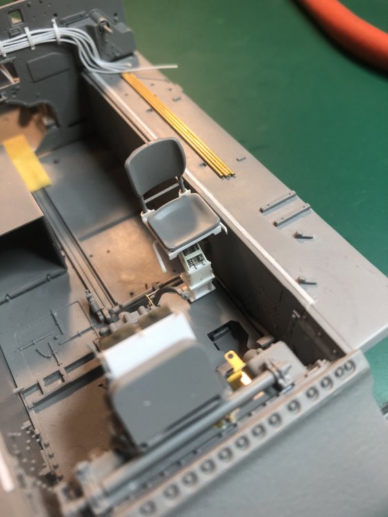
Test fitted the scratch built seat. I think it should work fine. Just need to shorten the depth of the seat.
-
The second seat was already built. I was thinking of shortening the depth of the seat and using the kits seat cushion and possibly the back of the seat if I can get it to fit. When you take out the turret the seats are visible.
-
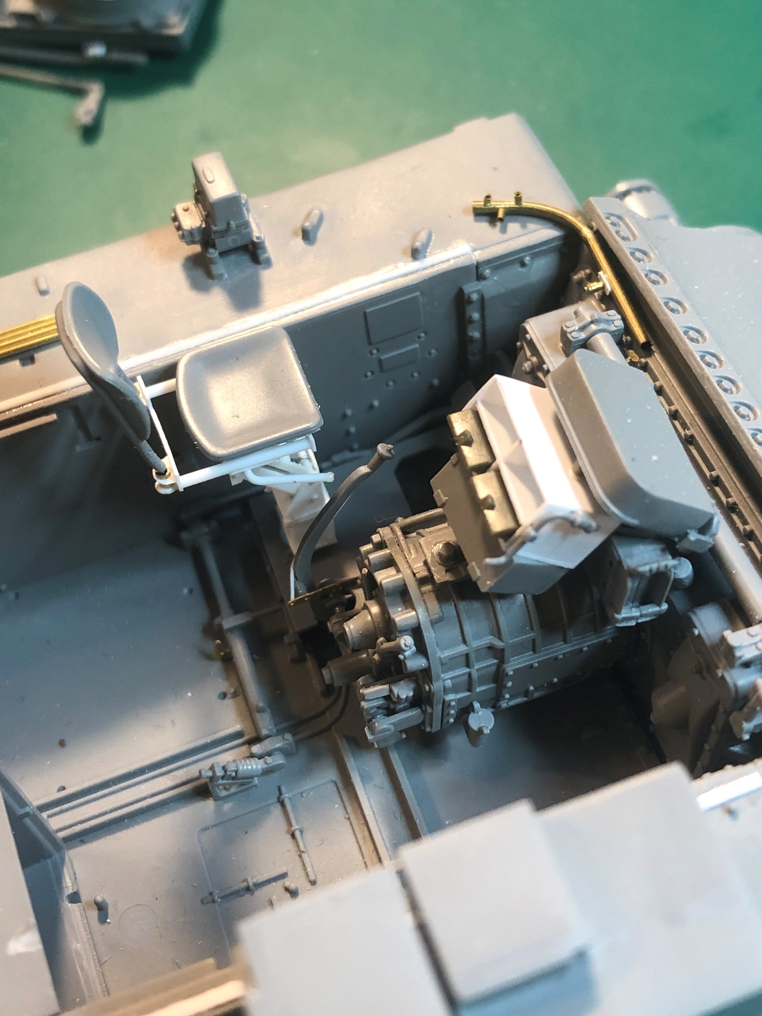
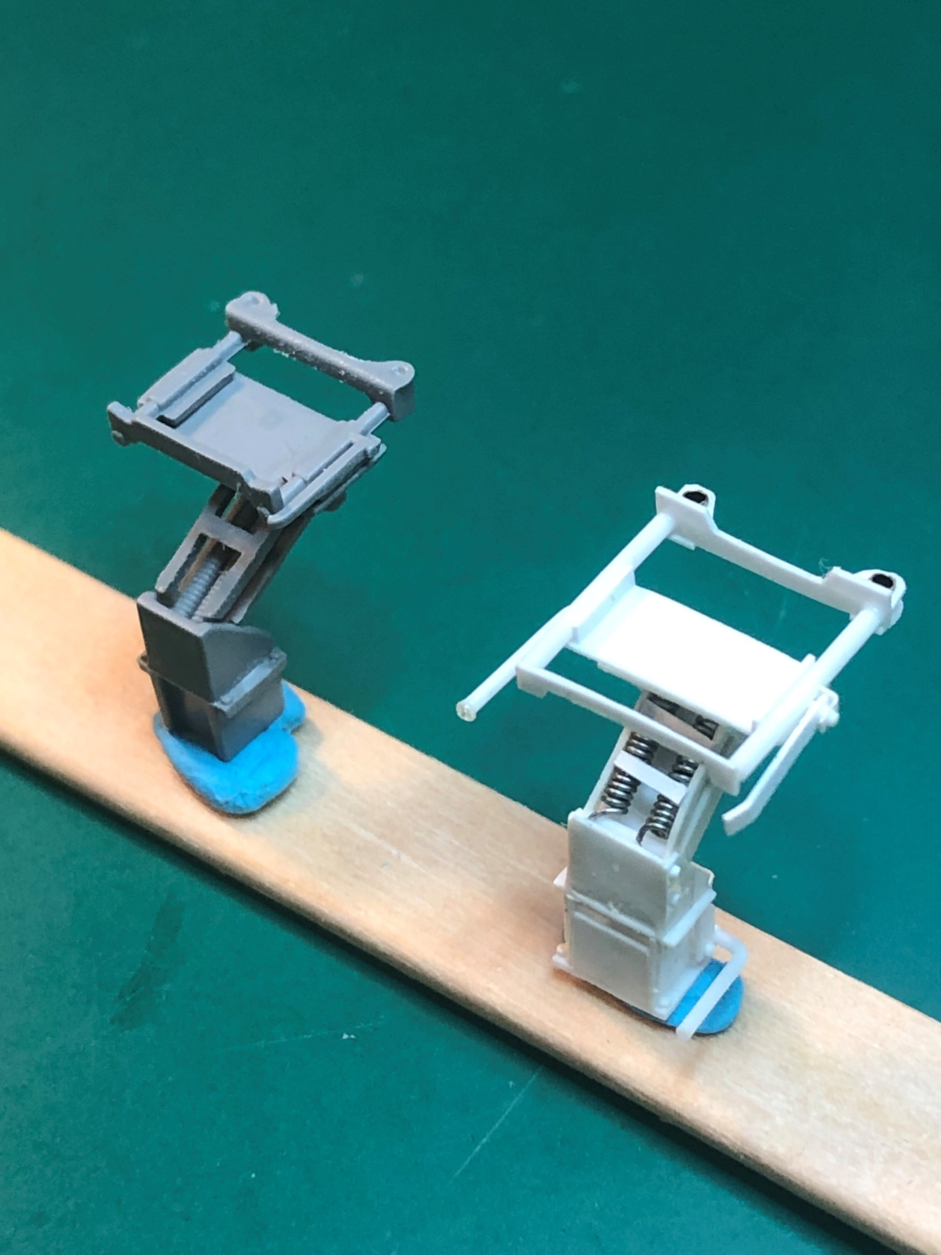
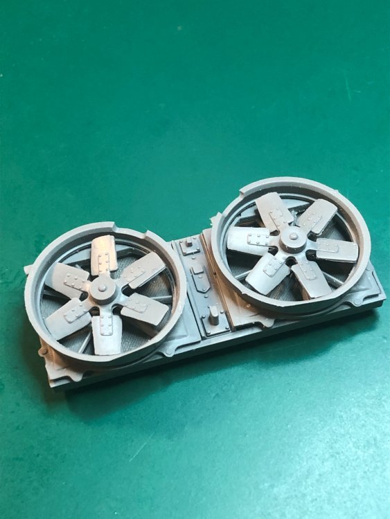
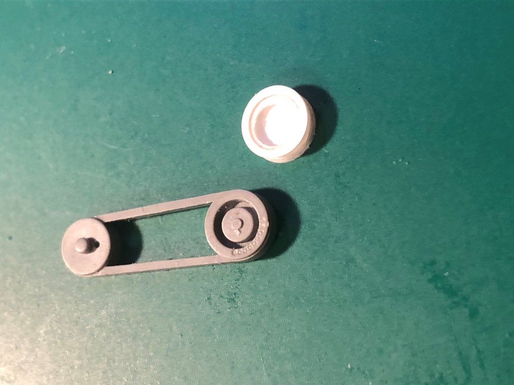
Continued on the engine compartment dry fitting the fans and worked on the fan belts doing some scratch building as I am trying to get two belts showing were the kit has only one. Scratch built the periscope holders on top of the transmission housing since the kit has them molded in. Below the power train assembly is what I scratch build for the M4A3 I was building from an Asuka kit (previous work in progress that I did not complete). Came pretty close to what the kit has in size and dimensions. On the differential housing I added casting marks (under the primer holder, photo etch). Added the clutch and throttle linkage and test fitted the floor plate for the drivers seat. Put together the kit seat and then compared it to one I scratch built. I actually think I prefer the scratch built one. Anyone have thoughts on which seat to use?


-
Amazing work. The camo uniforms are incredible. Stunning.