FME erk Posted January 9, 2021 Author Posted January 9, 2021 Sorry Phil The Gas detection circle was to detect gas in the air or even when the aircraft was at dispersal . . . . 2
Fidd88 Posted January 9, 2021 Posted January 9, 2021 Yes. It would have reacted to Mustard, turning from a yellowy zinc-chromate colour to pink in it's presence. It may also have been reactive to phosgene. As the German stance on using chemical weapons was unknown at the outbreak of war, but they'd been enthusiastic exponents of chemical warfare, in the Great War, the RAF was fully ready retaliate with mustard, were the Germans to use it first, and It was likely as much to indicate contamination from our own gas ordnance as enemy chemical attacks. Bombers carried circular indicators, around 9-12 inches in diameter, usually (but not exclusively) on the upper tailplanes, starboard side. Fighter aircraft has square indicators, usually on the port wing arranged so that the diagonal of the square was aligned with the chord line of the wing, again on the upper surface. By mid '41 these had largely disappeared from RAF aircraft. Similar patches can be found on RAF vehicles of the period. Such preparedness on the part of the allies was evidenced by the disaster at Bari in December 1943 when it is thought several ships carrying mustard were sunk in flames at the harbour. Bari disaster 7 1
Bomber_County Posted January 10, 2021 Posted January 10, 2021 Thanks guys, you learn something everyday, always curious about its origin...... 5
Fidd88 Posted January 10, 2021 Posted January 10, 2021 No problem. It always amazes me the breadth of knowledge in forums such as these, this was just one I happened to know a bit about. I can't remember what groceries I need - but this sort of stuff just seems to stick in my memory! Lord knows why... I forgot to mention that such gas-indicating paint was also applied to British field-guns, trucks, tanks and much else from the pre-war period until 1941, until it became evident we'd not all be clobbered with this muck at the outbreak of war. The "Keep Calm and Carry On!" poster is thought to have been designed to be read wearing a gas-mask. It was never actually issued in war-time, as it was expressly meant to be put up in the aftermath of a gas-attack. As the Bari incident shows, there was still considerable preparation for retaliatory chemical warfare in anticipation of the Germans resorting to it as the Third Reich began to collapse. Probably the only thing that prevented it, was the Germans lacked the delivery capability in long range bombers that the allies possessed. Just as well really. 5
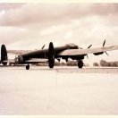
Kaireckstadt Posted January 10, 2021 Posted January 10, 2021 19 hours ago, FME erk said: While waiting for Mr. Surfacer to dry through I cracked on with a few other small jobs . . . Decided to put down a riveted floor . . . ND644 carried a No.1 Group gas circle on her nose so . . . and finally I modified the pilots seat . . . its time to go out so more next week Ian That looks great, Ian! A lot to do with all that riveting, but worth the effort! Do you have a foto of your Lanc with that gas circle on the fuselage? Never heard of it before! Just know that there was one on the bulletproof panel for the pilot, or is that wrong? 4
FME erk Posted January 10, 2021 Author Posted January 10, 2021 Kai If you trawl the first page you will see the actual aircraft I am going to model and you can see the gas patch circle on her nose. The yellow circle on the head rest of the pilots seat, also seen on the armour head rest of the Mosquito navigator, is to indicate that its armour and could affect the aircrafts compass and not for the same purpose as the yellow circle on the nose . . . Thanks for the compliment , always appreciated Ian 5
Kaireckstadt Posted January 10, 2021 Posted January 10, 2021 57 minutes ago, FME erk said: Kai If you trawl the first page you will see the actual aircraft I am going to model and you can see the gas patch circle on her nose. The yellow circle on the head rest of the pilots seat, also seen on the armour head rest of the Mosquito navigator, is to indicate that its armour and could affect the aircrafts compass and not for the same purpose as the yellow circle on the nose . . . Thanks for the compliment , always appreciated Ian Thanks for the explanations, Ian! You are a real expert on the Lanc! Next time I will use my eyes. I have a lot of literature about the Lanc, but have neither seen a photo with this feature nor knew the explanation for that so far! Keep on with your amazing work! Cheers Kai 6 1
FME erk Posted January 10, 2021 Author Posted January 10, 2021 23 hours ago, Fidd88 said: Yes. It would have reacted to Mustard, turning from a yellowy zinc-chromate colour to pink in it's presence. It may also have been reactive to phosgene. As the German stance on using chemical weapons was unknown at the outbreak of war, but they'd been enthusiastic exponents of chemical warfare, in the Great War, the RAF was fully ready retaliate with mustard, were the Germans to use it first, and It was likely as much to indicate contamination from our own gas ordnance as enemy chemical attacks. Bombers carried circular indicators, around 9-12 inches in diameter, usually (but not exclusively) on the upper tailplanes, starboard side. Fighter aircraft has square indicators, usually on the port wing arranged so that the diagonal of the square was aligned with the chord line of the wing, again on the upper surface. By mid '41 these had largely disappeared from RAF aircraft. Similar patches can be found on RAF vehicles of the period. Such preparedness on the part of the allies was evidenced by the disaster at Bari in December 1943 when it is thought several ships carrying mustard were sunk in flames at the harbour. Bari disaster 142 Squadron was trained to deliver Gas. They had a facility at RAF Grimsby and they stored the canisters in a Robin hangar over the far side of the airfield. Air14/2738 states: " 5th May 1942 a hangarette be erected at Grimsby for the purpose of storing SCI's (Service Chemical Installation) the name given to bombs containing gas ". It goes on to say . . . "The covering is Uralite, which would shatter in a blast but the building would not collapse". Strangely I have never seen a photo of a squadron Wellington with a gas circle but after they transferred out in November 1942 the Lancasters didnt have the gas patch on their nose until October 1943 at the earliest that I am aware . 3
Kaireckstadt Posted January 11, 2021 Posted January 11, 2021 7 hours ago, FME erk said: 142 Squadron was trained to deliver Gas. They had a facility at RAF Grimsby and they stored the canisters in a Robin hangar over the far side of the airfield. Air14/2738 states: " 5th May 1942 a hangarette be erected at Grimsby for the purpose of storing SCI's (Service Chemical Installation) the name given to bombs containing gas ". It goes on to say . . . "The covering is Uralite, which would shatter in a blast but the building would not collapse". Strangely I have never seen a photo of a squadron Wellington with a gas circle but after they transferred out in November 1942 the Lancasters didnt have the gas patch on their nose until October 1943 at the earliest that I am aware . Quite interesting to read, Ian! Where do you have all these sources from ? 3
FME erk Posted January 11, 2021 Author Posted January 11, 2021 Kai Most of it is first-hand accounts but the quotation is from the official Air Ministry document 'Air 14' My, (awaiting publication), new book contains many many first-hand accounts mixed in with the official records from the Operational Record Books, better known as the ORB's . . . Ian 3
FME erk Posted January 11, 2021 Author Posted January 11, 2021 I looked at the engines and their construction. I only anticipate building One to show it off and considered it for display in the diorama setting . . . The engine assembly is quite straight forward but as I said I only want one complete engine but there is a short cut that is not illustrated in the Instruction booklet. First photo is the almost final assembly where you add the individual exhaust onto/into the engine block . . . As mentioned, there is a short cut if you dont want to build ALL the engines and I cannot understand why the instructions dont even offer the alternative ? the sprue required is lettered 'Z' . . . The two long box items at the bottom have three tabs that slot into the back off the engine cowling so you can then just add the individual exhausts . . . Shown are my sets painted up, you only need to paint inside the box . . . Another reason for assembling these 'false' exhaust outlet is because, in my opinion, the exhaust shrouds, are way to large and to that end, once the exhausts are fitted I will be able to see just how far they extrude from the engine cowling. Only then will I be able to cut the shroud(s) down to size. Have a look at a number of those already built, they stick out to far then look at an actual aircraft, the difference IS noticeable. Thanks for looking in Ian 3 1
FME erk Posted January 11, 2021 Author Posted January 11, 2021 Evening all . .. I have managed to assemble the mock-up exhausts with the cowling cover, I dont think they look to bad . . . There are three points to which the box of exhaust stubs fixes inside the engine cowling A goes into Aa and B is the centre fixing point. Next up will be to make the fourth engine position very soon to display an engine . . . cheers Ian 4
BlrwestSiR Posted January 11, 2021 Posted January 11, 2021 Ian, would parts from a Tamiya Merlin work on the open cowl one? I've got lots of spare bits from all the Spitfires I did with a closed cowl. Mostly cylinder banks, heads and the small bits. Carl 3
FME erk Posted January 11, 2021 Author Posted January 11, 2021 Carl Many thanks for your suggestion . . . would the parts make up a complete engine ? If so I would consider placing it in the engine space . . . I would have to bow to your knowledge as to fitting it but I would certainly give it a try Cheers for that Ian 3
BlrwestSiR Posted January 11, 2021 Posted January 11, 2021 Ian, Let me see what I have. Usually you need the engine block and supercharger when doing a closed cowl on the Spitfire but I did convert one to a XIV so those parts may be around. Carl 3 1
BlrwestSiR Posted January 12, 2021 Posted January 12, 2021 I dug through my spares. I have a full engine sprue. Here's the core sprue. For the supercharger, Tamiya has three different variants (four actually as the Mustang has yet another but I need that one) The Spitfire VIII and IX have this one: The Spitfire XVI is this one: The Mosquito is this one: Here's the main engine sprue compared to the HK Lanc one. It's definitely more detailed. Let me know if you want the engine. For the superchargers, 5
FME erk Posted January 12, 2021 Author Posted January 12, 2021 Morning Carl I have sent you a PM many thanks Ian 3
FME erk Posted January 12, 2021 Author Posted January 12, 2021 Last night I was busy re-sizing the exhaust shrouds and placing fixing brackets to fit on the cowlings. Drying overnight, I cut them so they look more appropriate for fixing . . . . First photo shows the actual 4 tabs for fixing the shrouds Making up the brackets In situ on the kits cowling . . . another little modification to improve the appearance Ian 7
Bomber_County Posted January 12, 2021 Posted January 12, 2021 You’re motoring on this Ian, looking at the original photo of the shrouds, a tad “Heath Robinson” but at the time they didn’t have the luxury of time...... 2 1
BlrwestSiR Posted January 13, 2021 Posted January 13, 2021 In case others are interested, I thought I'd post these pics here. Doing a closer comparison of the various superchargers Tamiya had moulded for their kits, the one in the Mosquito looks to be the closest to the HK kit. I quickly pieced together one of the HK Merlins. Here's the Tamiya supercharger from the same angle: HK oil tank: Tamiya: For fun, here's the Eduard Merlin. This is just the block, one cylinder bank and supercharger. Comparing some of the other Eduard bits, it would also be a good choice for the Lanc. 2 2
FME erk Posted January 13, 2021 Author Posted January 13, 2021 Carl Thanks for the comparison photos. The Eduards bottom section has more detail for sure but if the Mossie super fits then I will take that. Many thanks again Carl cheers Ian 3
BlrwestSiR Posted January 13, 2021 Posted January 13, 2021 18 minutes ago, FME erk said: Carl Thanks for the comparison photos. The Eduards bottom section has more detail so if the Mossie super fits then I will take that. Many thanks again Carl cheers Ian I'll try to get to a post office later today or tomorrow. Carl 3
FME erk Posted January 14, 2021 Author Posted January 14, 2021 Thanks Carl. I look forward to receiving the parts in good time . . . Ian 2
FME erk Posted January 15, 2021 Author Posted January 15, 2021 As previously mentioned on the first page, two defects on the wings, the Port upper side had a second Dinghy stowage hatch and the starboard underside has landing lights . . . After applying Mr. Surfacer some weeks ago I have now eliminated both issues and hopefully you will be able to see the results as I hold the pieces in the correct light to photograph them . . . The next thing that wants attention are the undercarriage legs. In the photo you can see the 'hole' in the vertical strut. It would probably support the kit no problem but there shouldn't be such a hole therefore I shall be sinking some sprue glue in there to make good. Also, the 'Non-retracting bar needs removing for I have not seen any photos of this in place on a wartime aircraft, I suspect its used on todays flying examples . . . More to come best regards Ian 2

Recommended Posts
Create an account or sign in to comment
You need to be a member in order to leave a comment
Create an account
Sign up for a new account in our community. It's easy!
Register a new accountSign in
Already have an account? Sign in here.
Sign In Now