DocRob Posted December 30, 2020 Author Posted December 30, 2020 49 minutes ago, BlrwestSiR said: Just catching up on your build. The struts are really impressive. Just curious how you get the alignment on the joint where all three struts meet? You did the V first and when you add the third one, do you solder it on too? Until now, only the V is soldered. The connection is made with Albion Alloys four way Connecto connectors, which are bent the way the three struts have to align and the fourth is for mounting the wing on. The long struts will be soldered later, while attaching the wing. It may be necessary to shorten them a little, but this is too vague to be done now. Cheers Rob 4 1
BlrwestSiR Posted December 30, 2020 Posted December 30, 2020 Thanks for the explanation. That makes sense. I'll have to look into those Albion Alloys connectors. Carl 3
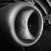
DocRob Posted December 30, 2020 Author Posted December 30, 2020 Something about compability of the Lukgraph Le Rhone engine. I went the extra mile and tested all cowlings in my stash, for whom a Le Rhone engine would be suitable, maybe somebody is interested. Mikro Mir Fokker D.V/E.VIII kit cowling fits (look at the plastic and it's one of the better parts) Aviattic Fokker D.V/E.VIII fits (note the shape differences to the above kit part, the Aviattic cowling shows four full cylinders, were the Mikro Mir one shows two full and two halfed cylinders) Wingnut Wings Le Rhone Camel fits tightly, not sure if it would turn, because I didn't assembled the firewall attachment Roden Fokker DR.1 cowl fits tightly as well, no idea if it is able to turn. And this is how the primed engine looks, ready to receive metal colours. Cheers Rob 7 1
GazzaS Posted December 30, 2020 Posted December 30, 2020 9 hours ago, DocRob said: Indeed Gaz, the material is very forgiving and the process seem to allow differently casted shapes, which reduces the parts count. As I'm new to printed parts, I tested primer and glues on residues. Tamiya rattle can primer doesn't do harm, but you definitely need CA for gluing, Plastic cement doesn't work. Cheers Rob If you ever find yourself inclined to build an early Nachtjager, these printed aerials by Gaspatch Models have been available for over a year. 3 2
DocRob Posted December 30, 2020 Author Posted December 30, 2020 Thanks Gaz, but the only night fighter in my stash is the ZM HE-219, where I have some metal antlers and a Fly Arado-234 in midbuild, with a Master set for the antennas. Cheers Rob 3
DocRob Posted January 5, 2021 Author Posted January 5, 2021 Back to the Fokker after all these festivities. If you are really bored by the perfectness of a Tamiya kit, this is for you. Some parts, I cleaned three times and still found blemishes while test fitting. Some parts, are barely recognizable as such on the sprues, they are just blobs of plastic, but there is nothing, which can't be solved by now. The good thing about the kit, is the general appearance of the fuselage covering fabric, which looks very realistic and you got the chance to use all your skills and tools. I don'tknow why, but the build has been motivating, where I can't explain why, I wanted to be sure about the fit of the fuselage, with the engine cowling mounted and test fitted for a second time. That was also necessary as I wanted to use the Aviattic PE firewall and access panel. The supplied firewall has no attachment lip to the four fuselage panels, it has to be glued flat on them, which I didn't like. I cut some spars from 0,5mm sheet, glued two together as a guide, cut a wider one, with the diameter of the hull, then attached the PE firewall and a last 0,5mm part as a guide for the cowling. As you can see, the front was taking shape, but the fuselage sides are bended inwards on the upper side. I loosely added another spar in a place, where it hopefully will be out of sight, to bend the fuselage correctly. First I thought about soldering the inner frame from brass tube, but with the spar, this seems unnecessary, I will try and use the horrible plastic part. (The spar is not final) Finally, I think I got it manageable. I never used that many tape and time while test fitting, but I think it was an important thing to do. Better now, than with painted parts. Cheers Rob 7
Bomber_County Posted January 6, 2021 Posted January 6, 2021 This one is being a bit of a hand full, I agree sometimes when they fight back it can be rewarding...... 4
GazzaS Posted January 7, 2021 Posted January 7, 2021 Kits like this have to be endured. If you want to depict a rare piece of flying history. 4
DocRob Posted January 7, 2021 Author Posted January 7, 2021 19 hours ago, Bomber_County said: This one is being a bit of a hand full, I agree sometimes when they fight back it can be rewarding...... 2 hours ago, GazzaS said: Kits like this have to be endured. If you want to depict a rare piece of flying history. That is very true, sometimes you have to show yourself, that you can do it. Progress is a bit slow, because of a lot of processual thinking. The good side on the bad plastic is, it's good to work with, not brittle and I haven't broken any part yet, even the fragile inner framing, a topic I could make no mark on, on my two WNW builds, where I broke struts and frames. Cheers Rob 3
DocRob Posted January 7, 2021 Author Posted January 7, 2021 First paint is flowing. I primed the inside of the fuselage and spar behind the seat gloss white for decaling with Lozenge and Plywood. Then I masked fields between the inner struts with kabuki, using a sharp blade to cut the frames free. These were sprayed in RLM66 then. Tomorrow after drying, I will decal the innards and paint some oils for the wooden floor, to simulate woodgrain. The Aviattic decals are not cookie cut, but it was a fast job, to cut them out. Cheers Rob 8
Jeff Posted January 7, 2021 Posted January 7, 2021 I'm really liking this build, Rob.............. sure would be cool to see a real one...... and to see one alive and flying would be a real gem.......... 1 1
DocRob Posted January 8, 2021 Author Posted January 8, 2021 Thanks Jeff, it's such a cool looking plane, sleek and reduced with only this parasol wing. I hope, I like it enough, to be tough enough for the task . Cheers Rob 3
DocRob Posted January 8, 2021 Author Posted January 8, 2021 After thinking about, how to attach the wider Aviattic seat with the given plastic, I decided to build my own seat tubing, mainly because there are no attachment points for the plastic at all. I drilled 0,5 mm holes into the 'spar' and used 0,7 mm tube for the construction, which takes 0,5 mm brass rods for the attachment. For soldering the front connections, I used Albions Connectos again. The tube construction will be removed for painting and decaling of the fabric parts of the spar. Cheers Rob 5
Bomber_County Posted January 8, 2021 Posted January 8, 2021 Rob, that seat looks like a 1960 design classic..........nice call on the tubing....... 2
DocRob Posted January 8, 2021 Author Posted January 8, 2021 15 minutes ago, Bomber_County said: Rob, that seat looks like a 1960 design classic..........nice call on the tubing....... Thanks Phil, design yes, comfy no with the aluminum backrest. I will try something new painting the seat, using two different tones of aluminium colour, with liquid mask for chipping and wearing. That counts as preparation for my first swirled aluminum cowl for another future build. Another game of find the three differences with the kit seat and the Aviattic one. The cushion is part of the Aviattic set. Cheers Rob 4
DocRob Posted January 8, 2021 Author Posted January 8, 2021 Today I decaled the inner fuselage parts with plywood and the faded inside of the Lozenge. This will be sealed matte tomorrow and dirtied a little. The woodwork were done with oils on Tamiya tan. The scratch on the lower fuselage panel will not be seen, I grained this part only for fun. The parts will be varnished too and get a little treatment to show some use. Cheers Rob 7
Administrators JeroenPeters Posted January 8, 2021 Administrators Posted January 8, 2021 Loving this to the max 5 1
GazzaS Posted January 8, 2021 Posted January 8, 2021 Really love your work with the tubing, Rob. That seat looks sweet.... and strong! Gotta get me some connecto. The rest of the interior is looking great, too. By the way, what size connecto are you using most? 2
BlrwestSiR Posted January 8, 2021 Posted January 8, 2021 Really great work Rob. I like the inner fuselage framing that you've done. I'll need to find some of those connectos as well. Carl 1
DocRob Posted January 9, 2021 Author Posted January 9, 2021 13 hours ago, GazzaS said: By the way, what size connecto are you using most? These are the sizes I have, got them cheap in a sale a while ago exactly for the planned purpose, using them for struts and tubing in WWI planes. I used them for the first time and like them, to be exactly. I used two of my three sizes. for the wing struts it was C-09 and for the seat, I used C-05. The numbers mean, you can push the Connecto into an inner diameter like the code says. The arm of a C-09 Connecto is square, measuring 0,6x0,6 mm, therefore fits into a 0,9 mm inner diameter tube max. With the flattened tubes, I made it worked well. The 05 variant is very easily bend, the others are quite sturdy. Hope that helps Cheers Rob 4 1
DocRob Posted January 9, 2021 Author Posted January 9, 2021 14 hours ago, JeroenPeters said: Loving this to the max 13 hours ago, GazzaS said: Really love your work with the tubing, Rob. That seat looks sweet.... and strong! Gotta get me some connecto. The rest of the interior is looking great, too. 12 hours ago, BlrwestSiR said: Really great work Rob. I like the inner fuselage framing that you've done. I'll need to find some of those connectos as well. Muchas Gracias Señhores, it's a daring but fun project. I wonder what will remain to be seen of the inner fuselage work through the opening for the pilot. I fear the moment, when I have to add the bent and partly misshaped inner frame into the fuselage halves, but for different reasons, I decided against rebuilding the frame from brass tubes. Let's see, if that was a wise decision Cheers Rob 3
BlrwestSiR Posted January 9, 2021 Posted January 9, 2021 Maybe use some plastic rod for the inner frame since it sounds like it's visual only and not structural? 2
DocRob Posted January 9, 2021 Author Posted January 9, 2021 5 minutes ago, BlrwestSiR said: Maybe use some plastic rod for the inner frame since it sounds like it's visual only and not structural? First I thought, I would use brass tube and use it structural, to give the inward bend front fuselage sides the correct widening. Instead my proposed solution, is to use a spar made from plastic sheet and cut the plastic framing to size. The plastic is soft and bendable, so I hope, I get it right. I don't think, that you can look that deep into the fuselage, that you will be able to spot the spar behind the ammo boxes. Cheers Rob 3
Kaireckstadt Posted January 9, 2021 Posted January 9, 2021 18 hours ago, JeroenPeters said: Loving this to the max Beautiful tubing and woodwork! 2
DocRob Posted January 12, 2021 Author Posted January 12, 2021 On 1/9/2021 at 3:54 PM, Kaireckstadt said: Beautiful tubing and woodwork! Muchas gracias Kai. Meanwhile the engine received some love, but some details still needed to be added or repaired, because I dropped the engine and broke some rockers and spark plugs. For painting, I used AK's Extreme Metals, which are great to work with. First I sprayed the complete engine in steel, then added some transparent blue (hard to see on the pics but it's there) on the heads of the cylinders for heat treatment, then used stainless steel for the rockers and finally aluminum for the casings. The exhausts were finished in copper. The whole engine got a black panel wash and then the steel pushrods were added. I will dirty the engine later with oil stains according to the general appearance of the Fokker. As a last step the ignition wires will be applied. The seat was sprayed light Aluminum and the was dabbed with AK's True metal paste in aluminum and dark aluminum, using my espresso machine as a guide for the look. The pic is bad, but gives an idea. Cheers Rob 8 1

Recommended Posts
Create an account or sign in to comment
You need to be a member in order to leave a comment
Create an account
Sign up for a new account in our community. It's easy!
Register a new accountSign in
Already have an account? Sign in here.
Sign In Now