Trigger Posted April 24, 2021 Posted April 24, 2021 Hello guys, As if I didn't have enough to do already , (with the Catalina underway and the DB605 engine), I Really couldn't resist to build an all time favorite of mine, and in a very large 1/18 scale too. The famous ME 109. It wil be a slow build because I intend to place a DB601 engine in the model, which it is now lacking. Now there is no other engine available in this size other than the DB605, so I ordered a 605, and I will try to convert it into a DB601 which was used in the E4. I will have to cut open the model to get the engine in place, this will be a bit nerve wrecking , as the aircraft is moulded with a complete fuselage and a loose nose cone made in one piece. So in order to get an engine that is visible I have to cut open the nose cone, but also the front of the fuselage. The engine will be completely visible, engine covers taken of, the bottom cowling with the oil cooler visible, (will have to scratch build that one). But enough said, here's the model I will not be doing this version , got some books from the shelve, and I am currently trying to decide what kind of version I will build, I am more leaning towards something like this, visually more interesting with the mottling .... As you can see, it's huge, the detailing is really impressive, look at some loose parts, Very impressive wheels,... Look at the detail of the inner lining of the wheel well, even unpainted it looks like the real deal Cockpit floor also great detail So I started with the model (head on) literally . Got the nose cone out, its a one piece moulding. Where the propellor meets the fuselage is a 1 cm thick piece of resin on the inside that has to come out, so started there, and removed the pour stub from the nose, Still some cleanup to do Then it was time to open up the nose in order to get the engine in withe the cooler, Opened the holes with a drill, there was a huge "blob" of resin directly behind the cowling, so had to sand a lot of it to get a Smoot finish, have to get to almost scale thickness in order for the cooler to fit directly behind the cowling. Butchered the cooler from the DB605, the cooler from the 605 is bigger so I had to cut a piece of, and had to grind the cooler all around because it is tapered and wouldn't fit in the fuselage, here are some pic's, Original db605 coolant tank.... And cut and tapered, (have to fill in the gap on the bottom inside ) , next on the list, this was only for testfitting, But it fits like a glove, the crankshaft also lines up exactly in the middle, Exhausts also line up nicely, That is it for now, more to follow, will be cutting up the nose next .....................can make no mistake there, because I need every part of that nose. Getting pretty nervous to do that, but that's for another time, Cheers, Frank 9 1
SapperSix Posted April 24, 2021 Posted April 24, 2021 Thats some nice big adjustments and additions work on a big bird. I am looking forward to watching your build. . 5
Kaireckstadt Posted April 24, 2021 Posted April 24, 2021 2 hours ago, Trigger said: Hello guys, As if I didn't have enough to do already , (with the Catalina underway and the DB605 engine), I Really couldn't resist to build an all time favorite of mine, and in a very large 1/18 scale too. The famous ME 109. It wil be a slow build because I intend to place a DB601 engine in the model, which it is now lacking. Now there is no other engine available in this size other than the DB605, so I ordered a 605, and I will try to convert it into a DB601 which was used in the E4. I will have to cut open the model to get the engine in place, this will be a bit nerve wrecking , as the aircraft is moulded with a complete fuselage and a loose nose cone made in one piece. So in order to get an engine that is visible I have to cut open the nose cone, but also the front of the fuselage. The engine will be completely visible, engine covers taken of, the bottom cowling with the oil cooler visible, (will have to scratch build that one). But enough said, here's the model I will not be doing this version , got some books from the shelve, and I am currently trying to decide what kind of version I will build, I am more leaning towards something like this, visually more interesting with the mottling .... As you can see, it's huge, the detailing is really impressive, look at some loose parts, Very impressive wheels,... Look at the detail of the inner lining of the wheel well, even unpainted it looks like the real deal Cockpit floor also great detail So I started with the model (head on) literally . Got the nose cone out, its a one piece moulding. Where the propellor meets the fuselage is a 1 cm thick piece of resin on the inside that has to come out, so started there, and removed the pour stub from the nose, Still some cleanup to do Then it was time to open up the nose in order to get the engine in withe the cooler, Opened the holes with a drill, there was a huge "blob" of resin directly behind the cowling, so had to sand a lot of it to get a Smoot finish, have to get to almost scale thickness in order for the cooler to fit directly behind the cowling. Butchered the cooler from the DB605, the cooler from the 605 is bigger so I had to cut a piece of, and had to grind the cooler all around because it is tapered and wouldn't fit in the fuselage, here are some pic's, Original db605 coolant tank.... And cut and tapered, (have to fill in the gap on the bottom inside ) , next on the list, this was only for testfitting, But it fits like a glove, the crankshaft also lines up exactly in the middle, Exhausts also line up nicely, That is it for now, more to follow, will be cutting up the nose next .....................can make no mistake there, because I need every part of that nose. Getting pretty nervous to do that, but that's for another time, Cheers, Frank Beautiful start Frank! Will follow closely! 4
Peterpools Posted April 25, 2021 Posted April 25, 2021 Frank OMG , what a fantastic start. Keep ‘em comin Peter 3
DocRob Posted April 25, 2021 Posted April 25, 2021 Good to see the exhausts align with the cowling, must have been a reassuring moment. You seem also to put the biggest obstacles behind you with a new project at first. Great work on an interesting project so far. Cheers Rob 5
Trigger Posted April 25, 2021 Author Posted April 25, 2021 1 hour ago, DocRob said: Good to see the exhausts align with the cowling, must have been a reassuring moment. You seem also to put the biggest obstacles behind you with a new project at first. Great work on an interesting project so far. Cheers Rob Hello Rob, That's indeed why i began with the nose section first, you never know how good the scale of the engine is in comparison with the rest of the model until you actually test fit the two. I must say i am happy with the fit. With the cooler in place in front of the engine I could see how the fit of the exhausts were going to be, and they line up exactly spot on. The turbocharger also lines up good with the left side of the cowling, so far so good. The next big thing is to scratch build a fire wall and make the connection with the engine bearers. Well step by step I will get there, thanks for the response, Frank 9
Bomber_County Posted April 25, 2021 Posted April 25, 2021 You’re a very brave man Frank, this is going to be good.......pulling a chair up before all the places get taken........ 6
Trigger Posted April 29, 2021 Author Posted April 29, 2021 So, it is time for an update, I decided to first do the cockpit, because when that is in place I can focus on cutting the nose section. The cockpit must be in place first so I have a reference where the front firewall exactly is situated in order to make a precise cut. So here are some pics, first the build up of the side panels some scratch build wires from lead wire Also sprayed some different tones of RLM02, so the panels look a bit weathered, scratch build air hose Both panels done and wired Pilot seat painted flat aluminum , sprayed some chipping fluid on it to weather the seat once it's painted in RLM02, Connected the sidewalls to the floor Test fitting the cockpit tub into the fuselage everything is held together with tape, the sidewalls line up nicely with the fuselage taped the rear bulkhead in place, that will need some filling and sanding before it fits It will be ok, when I squeeze the fuselage just a tiny bit it all lines up nicely And with the front firewall in place Cockpit all taped up all the seams will be gone once i glue them in place, So that is it for now, will now get the rear bulkhead in place and sand it to fit so I can glue the cockpit in place, Until the next time, Cheers, Frank 9
Kaireckstadt Posted April 29, 2021 Posted April 29, 2021 57 minutes ago, Trigger said: So, it is time for an update, I decided to first do the cockpit, because when that is in place I can focus on cutting the nose section. The cockpit must be in place first so I have a reference where the front firewall exactly is situated in order to make a precise cut. So here are some pics, first the build up of the side panels some scratch build wires from lead wire Also sprayed some different tones of RLM02, so the panels look a bit weathered, scratch build air hose Both panels done and wired Pilot seat painted flat aluminum , sprayed some chipping fluid on it to weather the seat once it's painted in RLM02, Connected the sidewalls to the floor Test fitting the cockpit tub into the fuselage everything is held together with tape, the sidewalls line up nicely with the fuselage taped the rear bulkhead in place, that will need some filling and sanding before it fits It will be ok, when I squeeze the fuselage just a tiny bit it all lines up nicely And with the front firewall in place Cockpit all taped up all the seams will be gone once i glue them in place, So that is it for now, will now get the rear bulkhead in place and sand it to fit so I can glue the cockpit in place, Until the next time, Cheers, Frank Wow that’s a huge amount of work you did Frank! The pit looks really awesome. Very nice detail you added and also the weathering looks spot on. The fit of the pit is also really nice! You did a great job so far! 6
Peterpools Posted April 30, 2021 Posted April 30, 2021 Frank Awesome progress. I front office looks and fits so good. Keep ‘em comin Peter 3
DocRob Posted April 30, 2021 Posted April 30, 2021 Like the others said, your pit is looking great and the detailing is spot on. It's good to see, that the tub is fitting the fuselage seemingly good. Cheers Rob 5
Trigger Posted April 30, 2021 Author Posted April 30, 2021 5 hours ago, GazzaS said: Whoa! that cockpit is smokin'! As is your FW190, great paint job! Cheers, Frank 5
Bomber_County Posted May 1, 2021 Posted May 1, 2021 Frank, amazing attention to detail, this going to be an epic build..... 5
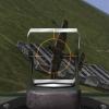
Trigger Posted May 2, 2021 Author Posted May 2, 2021 (edited) Hello Guys, Here's another update on the 109, first i had to make the wheel wells fit to the wings, they needed a lot of sanding and test fitting, but in the end they fitted, see for yourself, the left one is after sanding, the right one is the casting block with wheel well, After some struggling it was sanded to fit, Both wheel wells in place, quit difficult to get them in place, you need to slide them in from the nose, and then work them around the "corner" to get them in the wing, but I got there in the end, glued with epoxy, they are going nowhere anymore. Painted in RLM02, Painted the inside cover complete with the stitching, used a somewhat darker color for the stitching, and applied a wash in the wheel well Then I could fit the cockpit in position, I first glued a few "stops " in place left and right in the fuselage so the cockpit couldn't move to far backwards, Glued together, the sidewalls were glues later on, they line up with the fuselage nicely now, Test fitted the rear part of the canopy, and smoothed the backside with epoxy filler and sanded to fit, And after painting, Also put in the landing gear, wasn't easy to get the right angle Once the epoxy dried the angle was perfect Finally put my attention to some cockpit details like the revi gunsight and the control stick , And with a decal on the body of the gunsight, the brackets need to be painted in black yet, and I have to place the reflectors, but getting there, And the control stick.... That's it for now, the moment is getting near to cut the fuselage to accommodate the engine ......... Cheers, Frank Edited May 2, 2021 by Trigger spelling mistake 10
Kaireckstadt Posted May 3, 2021 Posted May 3, 2021 What a progress Frank! That‘s a lot of things you managed within the last update. The wheel-wells caused a lot of work but this paid off. Looks beautiful now! Also the stick and the gunsight look really nice with crisp details. You are really fast and straightforward with this build! Will be in the first row to see the progress! 6
Trigger Posted May 6, 2021 Author Posted May 6, 2021 Hello Guy's, here's another update on the Me109, Finally made the first cut in the fuselage...............first drew the cutting lines with a pencil..... Used my thinnest razor saw in order to get as little as possible material loss, so now i have one gaping hole...... next step is to fit the firewall Cut the top of the firewall off so I could get the platform in with the MG'S....used epoxy to get a good bond with the sidewalls, otherwise the dihedral of the wings could be off, when the epoxy dried everything was as solid as before the cut. Test fit of the gun deck, (this is the gun deck of a Gustav, I will use this one and scratch build the the proper gun deck for an Emil) Now I have to make the gun deck fit with the front windshield. Test fitted it under the cowling, Cut of some parts that are not present on an E model, the back wall was cut so the cowling can line up withe the front windshield Test fit, still a big gap, back to sanding and cutting............. Almost there, still a gap of 0,5 mm, a bit of sanding and it will fit with a minimal seam, witch the real aircraft had also well that is it for now, doesn't seem much, but you have to think twice and cut once, so I am fitting and sanding a lot in order to get everything to fit, and then I can move on to scratch building the mounting brackets for the MG'S, cheers, Frank 9
harv Posted May 6, 2021 Posted May 6, 2021 Good God Frank, I've totally missed this. So nice, detail is excellent and your work on it outstanding !......harv 3
Kaireckstadt Posted May 6, 2021 Posted May 6, 2021 Harv is completely right Frank: Awesome work and even if you think it’s not much I can fully understand you (I’ve never sanded and fitted so much as with my Mirage build): It IS much! 4
Trigger Posted May 6, 2021 Author Posted May 6, 2021 1 hour ago, Kaireckstadt said: Harv is completely right Frank: Awesome work and even if you think it’s not much I can fully understand you (I’ve never sanded and fitted so much as with my Mirage build): It IS much! Hi Kai, Well I guess you are the expert in sanding and fitting! Great work on your landing gear by the way, the end is in sight, Frank 4
Peterpools Posted May 7, 2021 Posted May 7, 2021 Frank Right with Harv and Kia - incredible work. Keep ‘em comin Peter 4
HubertB Posted May 7, 2021 Posted May 7, 2021 Great work, Frank. Probably a camera-induced parallax error, and also linked to the « test-fitting » method, but the windscreen frames appear slanted to the right (viewed from the front) compared to the vertical reference of the fin, on your fifth pic from the top. Hubert 3
Trigger Posted May 7, 2021 Author Posted May 7, 2021 9 hours ago, HubertB said: Great work, Frank. Probably a camera-induced parallax error, and also linked to the « test-fitting » method, but the windscreen frames appear slanted to the right (viewed from the front) compared to the vertical reference of the fin, on your fifth pic from the top. Hubert Hi Hubert, you are absolutely right , at that point I didn't have a frame on the front of the windshield, so it is "dangling" in mid air in that picture, a few pictures further I put in the front gun deck, so now the front windshield can lean on the frame. Now it aligns much better, but still not perfect, the front of the windshield has two three-quarter windows that need to be put in place in the right angle, that will also help to get the windshield in the right position. the last picture from my reference book shows this pretty good. Thanks for the input by the way, two pair of eyes always see more than one pair, Cheers, Frank 4 1

Recommended Posts
Create an account or sign in to comment
You need to be a member in order to leave a comment
Create an account
Sign up for a new account in our community. It's easy!
Register a new accountSign in
Already have an account? Sign in here.
Sign In Now